Embed Size (px)
Citation preview

Tekla Structures 21.0
Arvydas Kublickas

2
INTEROPERABILITY

Intergraph Smart™ 3D• For transferring model data between Intergraph's
Smart™ 3D and Tekla Structures
• Improved in latest versions
3

Aveva PDMS interoperability• Improved workflow with Aveva PDMS
• New bi-directional link introduces higher level of details and
better management of information transfer
– Bi-directional link based on IFC for transferring and
converting to native parts
4

Revit Interoperability• Work efficiently with the Design Team using Revit
• For collaborating and clash checking
– Use standard Autodesk approved IFC files
• For reusing accurate Tekla geometry in Revit for Drawings
– Tekla: Export to Revit for Drawings (Warehouse)
– Revit: Import from Tekla Add-In (Tekla.com)
– Improved export/import speed, general reliability and
fixed member rotation errors
– See more on teklastructures.support.tekla.com
5

IFC Change Management
• For detecting, managing and reacting
to changes in IFC models
• Aids Engineers and Detailers to
manage changes in
– Aveva PDMS interoperability
– Design teams involving Architects
and MEP designers
– Engineer – Detailer workflow
– Internal change management
6

IFC Change Management• Updated user interface
– Update Native Parts button
• Control over what properties are
update
• Feedback over success
– New columns Native Part and Native
Value
• Better default settings
for detecting changes
• Better support for
updating plates and slabs
7

BIM Publisher
• Automates your model and drawing exports
• BIM publisher take cares of exporting DGN, DWG, IFC
models and DWG drawings form multiple models in one
go
• Can be scheduled to run during nights
• Now also supports
– Export to PDMS
– Export to Revit
8

Improved IFC export
• Faster and more robust IFC export
• Strengthens Tekla’s Open BIM approach and speeds up
interoperability
9

Improved IFC export• Improved export of
– counter plates with chamfers
– poly-beams
• Dramatically improved IFC export time
• New options
– export IFC with minimum properties
– export flat and wide beams as plates
– Option to export using current view colors
• Export showing status by color!
– to set accuracy for poperties
10
SketchUp Export & Import
• Import now supports SketchUp version 2015
• Provide additional business benefit by being able to
communicate your design intentions to those outside of the
design team in sketch form
11
Tekla SketchUp Pro Render plug-in

Miscellaneous
• Improved IFC Object Converter
– Works better for objects with chamfers, e.g. contour plates
• Reference model DWG import
– DWG reference model import now supports ACAD2014
12

13
MODELING

Direct Modification
• Easy and intuitive
way to insert custom
parts
– Preview when
placing and
moving
– Immediate
editing of position
• Easy editing of
position
– Move and rotate
14

Direct Modification• Construction Geometry
– Points, Lines, Circles and Planes
• Construction circles
– Now true circles providing accurate snapping
– Continuous solid line is easier to snap to
– Improved performance for large diameter
circles
15
Check radius
Re-size
Offset
Move end pointsOld: Straight segments
Dashed line
New: True curve
Solid line

Clip Planes
• Snap to edges on clip planes
– Own special grey snap
symbol
• Model to intersections of
parts and skewed planes
– Great for skewed and
sloped stiffener and
gusset modeling
16

Split Poly-beams
17
• Split command now
supports poly-beams
– Start the
command
– Pick the poly-
beam
– Picked the point
– Command stays
active for
repeated use

New Copy Command• Copy all content to another assembly or cast unit
– Edit > Copy Special > All Content to Another Object
– No need to select each object to copy
– Copies all of these from one assembly to another
• Secondary parts
• Reinforcement, bolts,
and welds
• Cuts, fittings, and
edge chamfers
• Sub-assemblies
• Components
– Quick and easy way to
reliably move detailing to another identical assembly
18

New reference models management
• More efficient management
of reference models
• Total new user interface
introduced
– New side pane list
– Group reference models
– Control visibility
– Layer control
– Change detection
– Works with Organizer
19

Organizer & Object Browser
• Improvements in reporting
– Show assembly content
– Combine identical rows
• Better controls for automation
– Organizer specific filters
– Filter model content:
• Choose to include or
exclude
the native model
• Choose reference models to
include or exclude
20

21
STEEL MODELING
Numbering
22
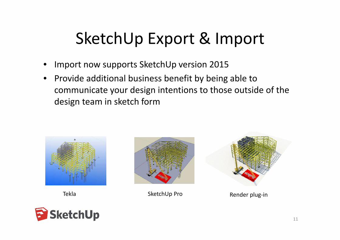
• Welds in assemblies
– Option to check welds when
numbering assemblies
– Number of welds must be
the same
– Weld properties must match
• Size, type, reference text,
UDAs, primary and
secondary parts, etc.
• Polygon weld geometry
must match to within
1.0mm

Numbering
• Stud Pop-marks– Stud pop-marks are now
taken into account in part numbering
• Improved information in the numbering log– amount of objects
checked
– time taken for numbering steps
23
Numbering 748 parts.Part numbering done in 2sNumbering 0 reinforcing barsReinforcing bar numbering done in 0sNumbering 340 assemblies or assembly familiesAssembly numbering done in 1sNumbering 340 assemblies or assembly familiesFamily numbering done in 0s
Numbering 748 parts.Part numbering done in 2sNumbering 0 reinforcing barsReinforcing bar numbering done in 0sNumbering 340 assemblies or assembly familiesAssembly numbering done in 1sNumbering 340 assemblies or assembly familiesFamily numbering done in 0s

Numbering
• Ignore part rotation for named assemblies
– Anchor rods and other assemblies can now get same marks regardless of rotation
– XS_EXCLUDED_PARTS_IN_ORIENTATIONAL_NUMBERING
– List part names to ignore when checking orientation
– Wild card use supported
24

Miscellaneous
• Weld command shows main part
– Weld main part briefly shown red
– Weld secondary part briefly shown yellow
– Immediate feedback that weld was created as planned
25

Plates from built-up sections• Improved
– Support for poly-beams, including arch chamfers
• New options:
– Numbering settings
– Mapping part and assembly mark
– Individual plate settings (web vs flange)
26

Explode and combine poly-beams
• Explode a poly-beam into beams
– Properties are mapped to the
beams
27

Explode and combine poly-beams
• Combine beams into a poly-beam
– Poly-beam gets the properties from
the first picked beam
• Options
– Intersection and nearest point
options
– Remove consecutive collinear points
– Chamfer options
28

Complex Poly-beam Creation
• Create complex curved poly-beam
shapes
– helicoidal
– elliptical
– Aids in the layout of complex
geometry such as stadium seats,
architectural steel, stair cases etc.
29

Surface Generation• Creates a surface between two poly-beams
– Helps to create complex plates:
• stringer plate for spiral staircases
• Girder webs and flanges for bridges
– Simplifies input of points to define geometry
– Easy editing by using direct modification to
change the input beams
• Notes
– Internally uses component 19
– Can be unfolded by plate tools
if using the ‘add part’ option
30
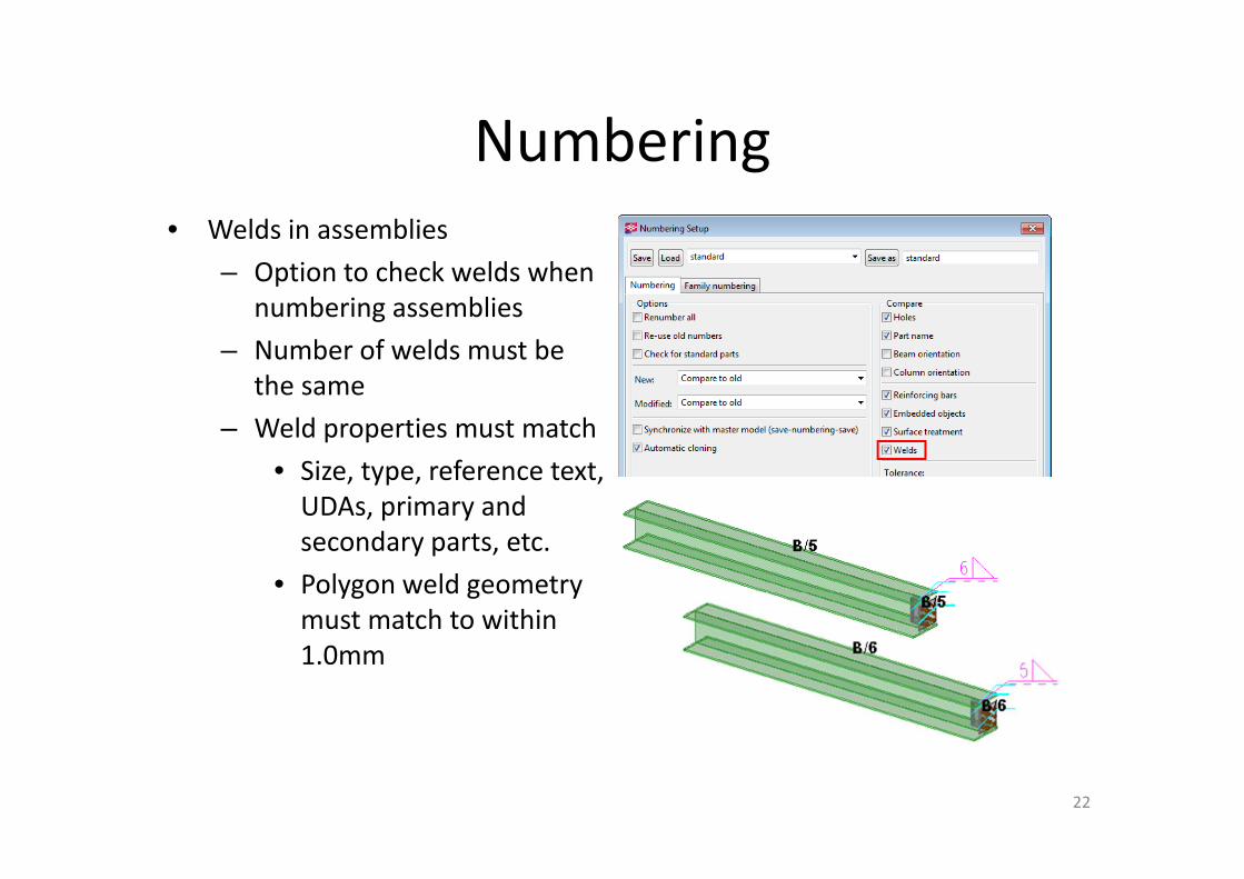
Complex modeling
• Combine Complex Poly-beam and Surface Generation, Array
Tools, and Unfold Bent Plates to layout complex geometries
• Create 3D plate beams that won’t roll
31

Plate Work Tools
32
• Unfolded Bent Plate creates an unfolded version from a bent
plate that has been created using attach parts
– Maps the detailing
– Unfolds any bent plate created attach part
– Pick position to place the unfolded plate
– Only supports sharp bends
– Unfold at center line or common
edge
– Creates
drawings

Squaring Cuts
• Create the minimum perpendicular cut
for beveled holes and cuts in plates
– Input is a part or a part cut
– For plate burners which do not
support beveling
– Easier fabrication and fitting
33

Squaring Cuts• Supports any cut profile shape
• Unfolded plates modeled so they are cut
straight
• Supports hole tolerance/offset
34

Circular Platform
• Create a curved platform
– Includes decking
– Perfect for platforms on storage tanks, silos, etc.
– Options to control railings
– Create full 360° platforms
– Option to create a radial grid
35

No Paint Area Between Parts
• Creates a no paint area between
overlapping surfaces
– Compliment to the No paint area
extension which works with bolted
parts
– Overlapping parts do not need to
be bolted or welded
– Automatically updates when the
parts are updated
– Easily build-in no paint
functionality
to custom components
36

No Paint Area Between Parts
• Create for the whole contact area or clearance from the
contact area
• Define the no-paint surfacing attributes
• Specify the allowable gap
– Create no paints areas even when
parts don’t touch, such as erection
tolerance gaps
37

38
CIP MODELING

Polyline pour break
• Ortho shows 45°/90° angle
• Closed polygons + modify
39
• More flexibility in pour break
creation
• Less ”workaround” pour breaks

Pour break adaptivity
• Faster and more reliable pour break functionality
– Pour breaks adapt to changes in geometry
• Less deleting and remodeling existing pour breaks
• Existing pour properties and information is not lost
• Modifying is easier
40
+ 1 beam + 2 beam
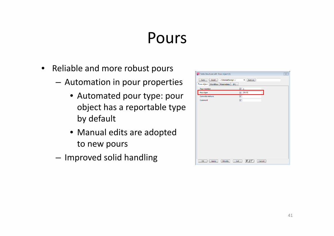
Pours
• Reliable and more robust pours
– Automation in pour properties
• Automated pour type: pour
object has a reportable type
by default
• Manual edits are adopted
to new pours
– Improved solid handling
41

42
PRECAST MODELING

Foor layout
43
• Easier using of universal floor tool
– Creating Floor Layout and changing slab direction
1 2 3 4 5 6
1. Polygon openings
2. Rectangular openings
3. Break line cut/split
4. Edit polygon input
5. Edit offset
6. Edit part widths and locations

Foor layout
44
• Easier using of universal floor tool
– Creating floors/roofs inclinations (+“alt“ key)

Foor layout
45
• Easier using of universal floor tool
– Editing polygon area

Foor layout
46
• Easier using of universal floor tool
– Panels dividing/dragging (+Alt; +Ctrl)

Foor layout
47
• Easier using of universal floor tool
– Single slab modification (right click)

Foor layout
48
• Easier using of universal floor tool
– Creating (polygon, rectangular) openings or breakline

Foor layout
49
• Easier using of universal floor tool
– Different layers offsets

Hole around part (92)
50
• Create multiple holes with one action

Hollow Core Reinforcement Strands
(60)
51
• Different strand placing cases for ends
• New option to consider openings

Floor Layout Cast In Place Filler
52
• Fill Floor Layout empty narrow stripes with cast in place
concrete
• Concrete fills inside Floor Layout area/boundaries

Mesh Bars and Mesh Bars by Area
53
• Intelligent (area) reinforcement with mesh
• Modify Mesh Bars by Area boundaries
with Direct Modification

Edge and Corner Reinforcement (62)
54
• U rebars becoms stirrups (lintel beam/column)

Edge and Corner Reinforcement (62)
55
• Better behavior for corner reinforcement in recesses, cuts and
openings

Reinforced Concrete Stairs (95)
56
• Automatic parametrical component
• Faster more intelligent results (especially later changes)

Beam End Reinforcement (79)
57
• Recognise reverse situation

Rectangular Column Reinforcement
(83)
58
• Improvement handling of intermediate stirrups
• UI changes

Sandwich Wall Window
59
• Possibility to handle continuous slope details by setting angle
or sloping length (before was problem: different settings
needed to be set if e.g. insulation layer thickness was
changed)

60
DRAWINGS
Dimension Rules
View Properties
Drawing
Beam
FrontBolts
Parts
TopGrids
Parts
Section Bolts
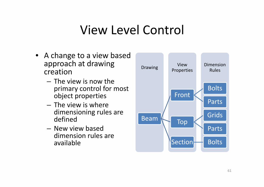
View Level Control
• A change to a view based approach at drawing creation– The view is now the
primary control for most object properties
– The view is where dimensioning rules are defined
– New view based dimension rules are available
61

The old dialogs...
62

... and its many sub dialogs
63

New Drawing and View Dialogs
• New dialogs for drawing and view properties– Intuitive & easy
navigation of drawing and view properties
– Less screen clutter and reduced ‘depth’ of settings by removing sub-dialogs
– View properties can now be shared across all drawing types
*GA drawings still use the old dialog, but views in GA drawings use the new view dialog
64
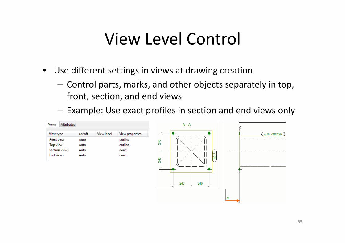
View Level Control
• Use different settings in views at drawing creation
– Control parts, marks, and other objects separately in top,
front, section, and end views
– Example: Use exact profiles in section and end views only
65
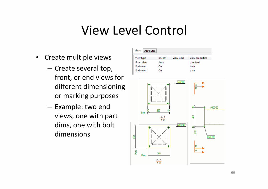
View Level Control
• Create multiple views
– Create several top,
front, or end views for
different dimensioning
or marking purposes
– Example: two end
views, one with part
dims, one with bolt
dimensions
66

View Level Control
• Automatic dimensioning of new and existing views
– Manually created views now use applied view properties
• Dimensioning rules will be run when the view is created
• Create section and detail views with automatic dimensioning
– Change the automatic dimensioning in an existing view
• Manually created dimensions will be kept
– New model content and changes will be dimensioned by the applied
dimension rules when drawings are updated
67
Dimensions created
along with the view
Scale comes from applied
properties
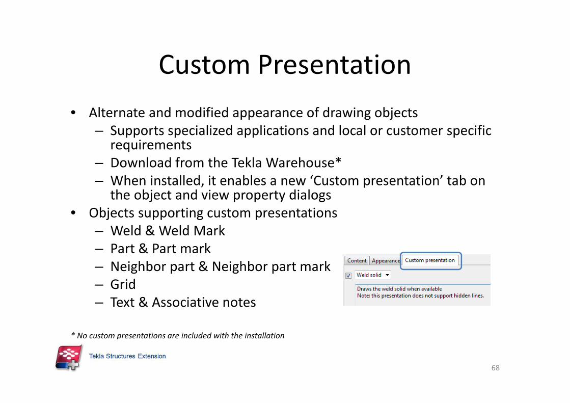
Custom Presentation
• Alternate and modified appearance of drawing objects
– Supports specialized applications and local or customer specific requirements
– Download from the Tekla Warehouse*
– When installed, it enables a new ‘Custom presentation’ tab on the object and view property dialogs
• Objects supporting custom presentations
– Weld & Weld Mark
– Part & Part mark
– Neighbor part & Neighbor part mark
– Grid
– Text & Associative notes
* No custom presentations are included with the installation
68

Custom Presentation - Examples
• Weld solid
– Show the weld solid in place of the weld path
69

Custom Presentation - Examples
• Laser layout projection
– Drawing all the lines slows down the laser and makes it too
dim to see on the layout table
70

Custom Presentation - Examples
• Can be used to create custom weld marks
– Offshore standards
– Inspection marks
– Etc.
71

• Show weld seams in all drawings
– Clarify the locations of welds
in drawings
– Snap to weld seams to
dimension the length
of the weld or weld offsets
– Control weld seams and
weld marks independently
Welds in Drawings
72

Welds in Drawings
• Welds and weld marks can now be shown in single-part drawings– Show weld seams and marks
in single-part drawings
– Aids in clarifying possible needs for surface preparation
• Weld and weld mark selection switches in drawings– To select welds, use the ‘Select
drawing welds’ switch
– To select weld marks, use the Select drawing marks switch
73

Reference in Cast Unit Drawings• Show architecture reference in Cast Unit drawings
• Architectural graphic facade
• Double check MEP and hole reservations
74

New dimensioning – shape, hole and
recess • Define shape, hole and recess types
75
1.Hole
2.Recess
3.Shape

Improved 2D details on drawings
• Drawing Symbol Manager allows you to save, change manage
2D details used on drawings
• Improves productivity when working with 2D details
• NEW in 21
– Renewed user interface
– Folder structure for 2D details
– Search
– Grouped together
– Also works for inserted DWGs
76

New Drawing Printing
• Easy preview and printing of drawings
– Preview drawings before printing
– Built in support for printing to PDF
– Produce PDF, print to printers, or plot to files
– Create a single PDF file
of all drawings
– Set line thicknesses
– Many other advanced
printing options
77

Miscellaneous
• See who has locked drawings– New “Locked by” column in drawing list shows the user
who has locked the drawing
• Curved section views– Drag and drop editing of the
view boundary and view plane
– View plane and boundary are now shown in the curved view and the parent view
– All parts inside the curved boundary are shown in the section view
78