Embed Size (px)
Citation preview
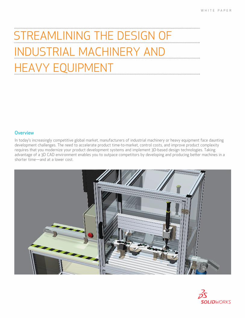
OverviewIn today’s increasingly competitive global market, manufacturers of industrial machinery or heavy equipment face daunting development challenges. The need to accelerate product time-to-market, control costs, and improve product complexity requires that you modernize your product development systems and implement 3D-based design technologies. Taking advantage of a 3D CAD environment enables you to outpace competitors by developing and producing better machines in a shorter time—and at a lower cost.
STREAMLINING THE DESIGN OF INDUSTRIAL MACHINERY AND HEAVY EQUIPMENT
W H I T E P A P E R
Introduction
When it comes to product development processes, the machinery industry is divided into two categories: machines that are designed from concept for one specific customer, and those that are designed to be sold in volume to many, as-yet-undetermined customers.
Machines that are designed for a specific customer usually start out as a Request for Proposal from a company to build a custom machine to do a specific task. A typical example of this category is packaging machines that are custom-built for a particular packaging purpose. Since these machines are custom-built to fit into a factory or into an existing system of other machinery—and often are fully customized, one-off designs—they cannot be easily reused or reconfigured to serve other purposes.
The second category includes “platform-based” machines, a design process that is similar to the way in which automobiles are developed and sold. Industrial machinery and heavy equipment fall into this category. Examples of industrial machinery include machining centers, conveyors, textile machines, and large paper copying and printing equipment. Examples of heavy equipment include street pavers, earthmovers, tree-grinders, and mining shovels.
Because these machines are designed to target a market segment as opposed to a specific customer, they come in different sizes, capacities, throughputs, and power ratings. Like automobiles, they can be easily reconfigured with options and accessories that meet the diverse needs of many customers. These machines are usually assigned model numbers, and customers can select an array of accessories and add-ons through catalogs and order sheets.
The initial design input for this type of machine comes from marketing, sales, engineering, and manufacturing. Sales and marketing process customer needs, while customers, engineering, and manufacturing provide feedback for technical improvements.
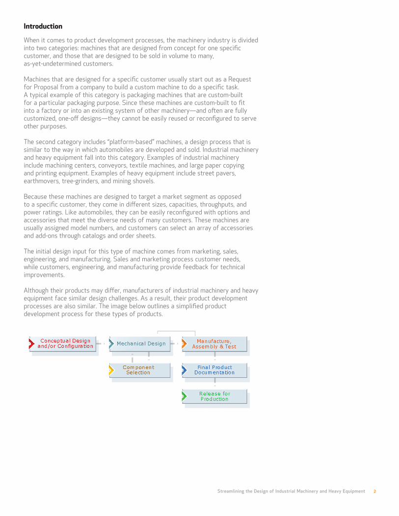
Although their products may differ, manufacturers of industrial machinery and heavy equipment face similar design challenges. As a result, their product development processes are also similar. The image below outlines a simplified product development process for these types of products.
Streamlining the Design of Industrial Machinery and Heavy Equipment 2

Makers of industrial machinery and heavy equipment face many challenges, as well as a competitive manufacturing landscape that requires the streamlining of product development processes.
Streamlining the Design of Industrial Machinery and Heavy Equipment 3
If the machine is a new design, the first phase will be conceptual design; if it is a variant to an existing machine, creating a new configuration will be the first step. Next comes mechanical and electrical design, including the selection of vendor-supplied components. Typically, the machine is prototyped to test its capabilities and to ensure manufacturability. The bugs are worked out through back-and-forth communication between engineering and manufacturing, including redesign and retesting. Once the design is proven out, production-quality drawings are completed and other documentation is created. Finally, the design is released for production.
Makers of industrial machinery and heavy equipment face many challenges, as well as a competitive manufacturing landscape that requires the streamlining of product development processes. Customers are demanding machines that are more customizable to their specific needs, that are easier to use, and that can be easily upgraded in the future as new technology becomes available. They are also requesting improvements in reliability, accuracy, power, and output. And, of course, these customers want all of this at a lower price. In addition, sales and marketing are demanding that these new machines be ready as soon as possible. To remain competitive in this fast-growing global arena, manufacturers of industrial machinery and heavy equipment must take advantage of innovative tools, technologies, and processes. To that end, manufacturers are modernizing their product development processes and tools.
In the past, engineers who developed these machines typically relied on 2D CAD tools. But since the very nature of industrial machinery and heavy equipment design involves a significant number of moving parts and mechanisms, they soon discovered that 3D CAD tools gave them an advantage over 2D CAD tools.
With SolidWorks® 3D CAD software, engineers can compress design cycles and cut development costs. 3D models are easier to visualize and understand than 2D drawings. Having the ability to shade and rotate a model in 3D space provides a much more complete and natural way to view the design for engineers as well as managers, manufacturing, and customers—it is about as close as you can get to holding the real part in your hand. And real-time photo rendering, called RealView, provides photorealistic viewing of your designs, so you can show customers and your design team what the finished product will look like. You can even capture videos to use for presentations, to show how the machine functions, or to document how the machine is assembled and disassembled. SolidWorks software also provides automatic 3D interference and hole alignment checking, so you can catch interferences early in the design process, before manufacturing parts, thereby reducing the number of prototypes, scrap, and costly rework.
Streamlining the Design of Industrial Machinery and Heavy Equipment 4
Modifying your design is as easy as clicking a dimension and entering a new value. Or, if you prefer, use SWIFT Instant3D, and just click on any face of a part and drag it.
With intuitive SolidWorks Heads-up User Interaction and SolidWorks Intelligent Feature Technology (SWIFT™), creating 3D models in SolidWorks software is easy. With SWIFT, it’s like having an expert consultant designing at your side. Techniques that can take users many months to learn in other CAD systems are built into SWIFT, so new users learn quickly. And for expert users, SWIFT speeds up design by automating tedious, repetitive tasks. SWIFT DraftXpert, FeatureXpert, and FilletXpert simplify the creation of drafted and filleted geometry.
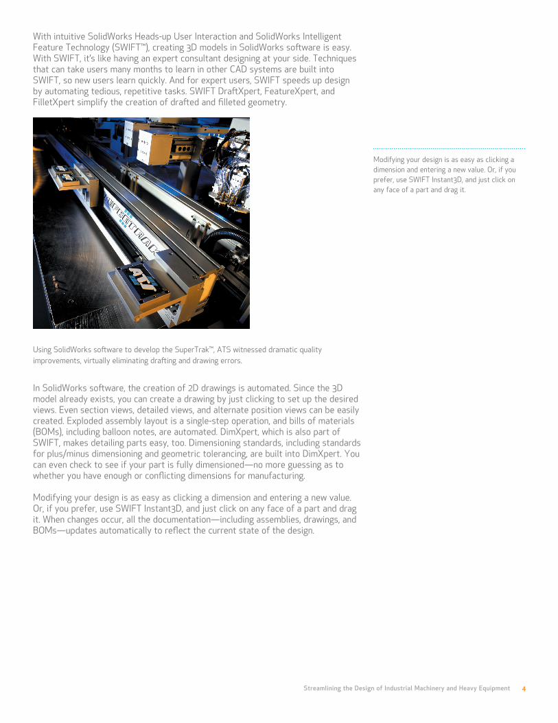
Using SolidWorks software to develop the SuperTrak™, ATS witnessed dramatic quality improvements, virtually eliminating drafting and drawing errors.
In SolidWorks software, the creation of 2D drawings is automated. Since the 3D model already exists, you can create a drawing by just clicking to set up the desired views. Even section views, detailed views, and alternate position views can be easily created. Exploded assembly layout is a single-step operation, and bills of materials (BOMs), including balloon notes, are automated. DimXpert, which is also part of SWIFT, makes detailing parts easy, too. Dimensioning standards, including standards for plus/minus dimensioning and geometric tolerancing, are built into DimXpert. You can even check to see if your part is fully dimensioned—no more guessing as to whether you have enough or conflicting dimensions for manufacturing.
Modifying your design is as easy as clicking a dimension and entering a new value. Or, if you prefer, use SWIFT Instant3D, and just click on any face of a part and drag it. When changes occur, all the documentation—including assemblies, drawings, and BOMs—updates automatically to reflect the current state of the design.

Streamlining the Design of Industrial Machinery and Heavy Equipment 5
The fastest way to design a new machine is to reuse and tweak an existing design. SolidWorks software provides capabilities to automatically create and store numerous configurations of the same design. So, when you modify a design, all the necessary drawings are instantly complete and ready to print. From a single base design, you can create and store thousands of machine variants, including documentation, with just a few simple inputs. Standard and vendor-supplied components are shipped with SolidWorks software in the Design Library and SolidWorks Toolbox, while additional vendor-supplied and user-created components are available at 3D ContentCentral®.
SolidWorks software also speeds design by providing specialized tools to automate the development of weldments, sheetmetal parts, and electrical and pipe routes. Additional visualization and communications tools, such as PhotoWorks™ software and SolidWorks eDrawings® files, enhance your ability to share your design with both technical and nontechnical colleagues, customers, and vendors. In addition to compressing design cycles and cutting development costs, SolidWorks software provides many tools to help you make better products and significantly reduce, and possibly even eliminate, prototypes. With the integrated SolidWorks Motion feature, engineers can make their assemblies move, and then capture information about the forces generated by this motion.
SolidWorks Simulation allows you to analyze components to see if they will function properly; for example, will the components break, fatigue, deflect, or vibrate excessively? What effects will temperature have on the machine? Is there enough airflow to cool the electronic components? With SolidWorks Motion kinematics and SolidWorks Simulation capabilities, you can minimize the need for physical prototypes and create more accurate, reliable, and innovative products.
DFMXpress provides design-for-manufacturing insight into whether your part can be machined easily, and offers advice on areas of a part that do not meet your company’s standard machining practices. Similarly, Design Checker checks your drawings to ensure that they meet the company’s drawing standards. Finally, TolAnalyst™ provides maximum/minimum tolerance stack-up capabilities to ensure that your machine will fit and function properly with the tolerance schemes assigned.
With SolidWorks Workgroup PDM and SolidWorks Enterprise PDM data management software, designers can easily manage all their project data. SolidWorks Enterprise PDM enables you to set up your own product development workflow, and keep all your team members connected, even if they are spread across multiple locations. SolidWorks Workgroup PDM allows you to share CAD models at any stage of the development process—from concept development through validation, manufacturing, assembly, and even after release to production.
Streamlining the Design of Industrial Machinery and Heavy Equipment 6
Flexibility and configurability of the design are paramount to accommodate the varying needs of many customers as opposed to those of one specific customer.
Visualizing design concepts Industrial machinery and heavy equipment design typically starts with a design specification, sometimes called a Marketing Requirements Document. The initial design specifications and the conceptual design are usually based on information gathered by sales and marketing from several current and potential customers, as well as on input from engineering and manufacturing. Occasionally, the “platform” design is even based on a one-off machine that was designed for a specific customer. Either way, flexibility and configurability of the design are paramount to accommodate the varying needs of many customers as opposed to those of one specific customer.
When you need to develop a design concept for a new industrial machine or a new piece of heavy equipment, having the ability to visualize parts and mechanisms in 3D is a critical advantage. To complete new product lines, you must often create variants by modifying previous designs, such as designing a 20-foot conveyor from a standard 10-foot model. At other times, you must utilize marketing or customer input to produce a platform that is completely new and different from anything you have ever produced.
In this case, conceptual design is often highly visual and interactive, requiring back-and-forth communication with customers and marketing personnel to convey ideas, garner feedback, and infuse the highest degree of market and customer intelligence into the development of a new product design concept. Accomplishing this step in a 2D environment is often slow, awkward, and ineffective, primarily because of the difficulties attendant to communicating 3D concepts solely with 2D engineering drawings.
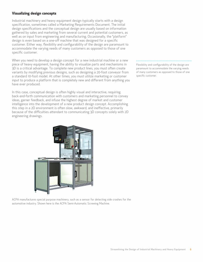
ACPA manufactures special purpose machinery, such as a sensor for detecting side crashes for the automotive industry. Shown here is the ACPA Semi-Automatic Screwing Machine.
Streamlining the Design of Industrial Machinery and Heavy Equipment 7
Creating a new design is as easy as entering new design parameter values in a spreadsheet.
With a 3D CAD system like SolidWorks software, however, you can produce 3D computer mock-ups and photorealistic images of design concepts—even moving animations of a machine in operation—along with drawings. This streamlines and improves the design communication process, both internally and externally. eDrawings files also reduce paperwork by eliminating reliance on actual paper drawings, so you can convey more complete design ideas to product development team members, customers, vendors, and even nontechnical personnel anywhere in the world.
Equipped with the enhanced visualization capabilities of 3D, designers and engineers have a more complete understanding of their designs, which in turn leads to higher levels of creativity. As a result, investigating new concepts and innovative features is faster and less costly. Since the creative work takes place in the 3D CAD system, you no longer have to rely on building physical models or conceptual prototypes. With the ability to visualize a design concept in 3D—and communicate that concept to customers, partners, and other product development team members—you can achieve trend-setting, innovative designs that heighten market impact and increase customer satisfaction.
Configuring product families
When designers need to develop families of products from existing machine platforms and new product designs, they also can benefit from 3D CAD tools. SolidWorks product data management software (SolidWorks Enterprise PDM and SolidWorks Workgroup PDM) and SolidWorks software search, data import, and configuration capabilities allow you to find previous designs and then automatically create design variations from the existing designs. The design configuration capabilities found in SolidWorks software enable designers to vary different design parameters—such as size, weight, travel length, and capacities—from an initial base design.
Creating a new design is as easy as entering new design parameter values in a Microsoft® Excel spreadsheet. In this way, you can produce models and related drawings for an entire family of products from a single design model.
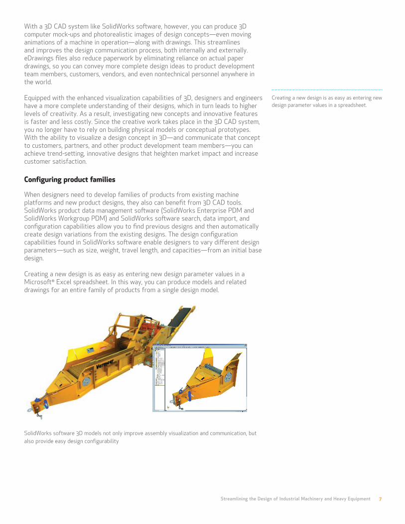
SolidWorks software 3D models not only improve assembly visualization and communication, but also provide easy design configurability
Streamlining the Design of Industrial Machinery and Heavy Equipment 8
With SolidWorks software, designers can use powerful sketching and modeling tools to create all the parts and subassemblies within a machine.
Collision Detection tools allow engineers to identify part collisions and interferences during mechanical design, when they are easier, less costly, and less time-consuming to address.
Making mechanical design more efficient The vast majority of industrial machines and heavy equipment can be thought of as one large mechanism that is comprised of hundreds—and even thousands—of individual components in various submechanisms, as well as power, pneumatic, and hydraulic systems. Traditionally, development of these products has relied on the use of 2D design tools, which carries the inherent disadvantage of trying to visualize a complex mechanism as a series of 2D component and assembly drawings. With 2D design tools, an engineer often could not determine if all the parts within a machine would fit together properly until the final, physical assembly. This often resulted not only in substantial amounts of scrap and rework, but also in costly production delays.
With SolidWorks software, designers can use powerful sketching and modeling tools to create all the parts and subassemblies within a machine. You can also employ SolidWorks Intelligent Feature Technology (SWIFT) to perform expert-level 3D CAD techniques without undergoing an extended period of training. In addition to viewing components as a single part or within the context of an entire machine or submechanism, you can use transparency and cut-away tools to reveal internal parts that were previously hidden.
Collision Detection tools allow engineers to identify part collisions and interferences during mechanical design, when they are easier, less costly, and less time-consuming to address. Because SolidWorks 3D CAD software is parametric in nature, it is fully associative. This allows you to make changes to a part and have those changes automatically update across all related parts, assemblies, and drawings. So you no longer have to worry about drawing views being out-of-date—they update automatically with changes to the 3D model. In addition, the associativity of SolidWorks software ensures that your BOM will always be up-to-date with the current state of your design. Specialized capabilities within SolidWorks software help engineers further simplify and automate the design of weldments, sheetmetal parts, and routed systems.
You can save time by utilizing SolidWorks software weldment capabilities to develop structural frames—including plates, weld beads, gussets, and caps—and cut lists generate automatically. SolidWorks software includes powerful tools for developing advanced sheet-metal designs in folded and flat states, and automates the creation of flanges, tabs, and corner reliefs. With automated flat patterns, you can design bent features that are automatically output as flat patterns for punching, laser cutting, and manufacturing. In addition, SolidWorks Routing enables you to automate the development of any routed system, including electrical cabling, pneumatic tubing, hydraulic lines, and piping.
Streamlining the Design of Industrial Machinery and Heavy Equipment 9
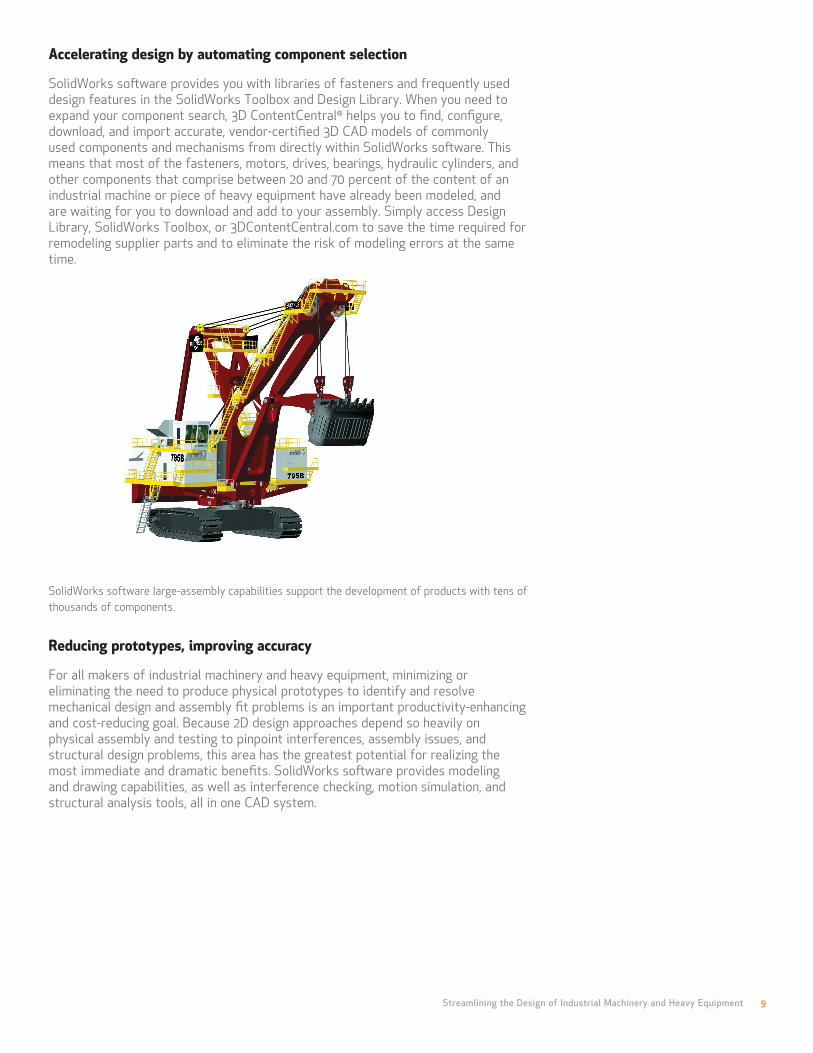
Accelerating design by automating component selection SolidWorks software provides you with libraries of fasteners and frequently used design features in the SolidWorks Toolbox and Design Library. When you need to expand your component search, 3D ContentCentral® helps you to find, configure, download, and import accurate, vendor-certified 3D CAD models of commonly used components and mechanisms from directly within SolidWorks software. This means that most of the fasteners, motors, drives, bearings, hydraulic cylinders, and other components that comprise between 20 and 70 percent of the content of an industrial machine or piece of heavy equipment have already been modeled, and are waiting for you to download and add to your assembly. Simply access Design Library, SolidWorks Toolbox, or 3DContentCentral.com to save the time required for remodeling supplier parts and to eliminate the risk of modeling errors at the same time.
SolidWorks software large-assembly capabilities support the development of products with tens of thousands of components.
Reducing prototypes, improving accuracy For all makers of industrial machinery and heavy equipment, minimizing or eliminating the need to produce physical prototypes to identify and resolve mechanical design and assembly fit problems is an important productivity-enhancing and cost-reducing goal. Because 2D design approaches depend so heavily on physical assembly and testing to pinpoint interferences, assembly issues, and structural design problems, this area has the greatest potential for realizing the most immediate and dramatic benefits. SolidWorks software provides modeling and drawing capabilities, as well as interference checking, motion simulation, and structural analysis tools, all in one CAD system.

Streamlining the Design of Industrial Machinery and Heavy Equipment 10
Instead of discovering interferences and clearance issues after manufacturing and assembling a machine, SolidWorks 3D CAD software enables you to observe a mechanism’s dynamic motion and pinpoint interference areas in the CAD system during the mechanical design stage. In addition to eliminating prototype and rework costs, using the 3D CAD system to identify clearance problems also saves engineers from having to remake part and assembly drawings. Changes made to resolve interference and clearance issues automatically apply to and update all corresponding models and drawings.
Since only a few prototypes might be built compared to the volume of machines to be produced, there is no way to ensure that part tolerances will be acceptable in production. You will therefore need a tolerance stack-up analysis of the machine’s key components to ensure that manufacturing deviations allowed by tolerances are acceptable. SolidWorks software provides an integrated stack-up analysis tool, called TolAnalyst, that allows you to automatically perform tolerance stack-up checks. TolAnalyst also identifies tolerances that have the greatest effect on the stack-up. Because you can tell which tolerances need to be tightened and which can be loosened, you can use less expensive manufacturing techniques—and save more money.
In addition to interference and tolerancing issues, mechanism kinematics and structural design flaws account for the majority of other problems that lead to costly design changes and subsequent production delays. With 2D-based design approaches, these assembly problems often go undetected until late in the development process during prototyping, during testing, or, even worse, in actual production. Nobody wants to discover these problems after a product is on the market, since this could result in field failures, recalls, warranty claims, and the erosion of both customer satisfaction and your company’s reputation.
With SolidWorks software, designers can choose from a robust set of design analysis tools to identify and fix potential design problems without having to build a prototype. In fact, these analysis tools will help identify many problems you could never find in prototyping. Not all assembly design problems involve parts banging into one another. Instead, they can stem from the unintended effects of motion, fatigue, and structural loads. Many issues of this type will not become apparent until well into the lifecycle of a machine or piece of equipment.
With the SolidWorks Motion feature, however, engineers can simulate the dynamic operation of a machine or mechanism. SolidWorks software can automatically set up constraints based on how you assembled the parts. You can apply forces and even devices such as motors to perform dynamic simulations that enable you to gain a complete understanding of the kinematics and dynamics of a design. SolidWorks Motion also allows engineers to size motors and actuators, determine power consumption, and lay out linkages. You can also optimize cams, understand gear drives, size springs and dampers, determine how contacting parts behave, and generate operating forces and loads for use in structural analysis.
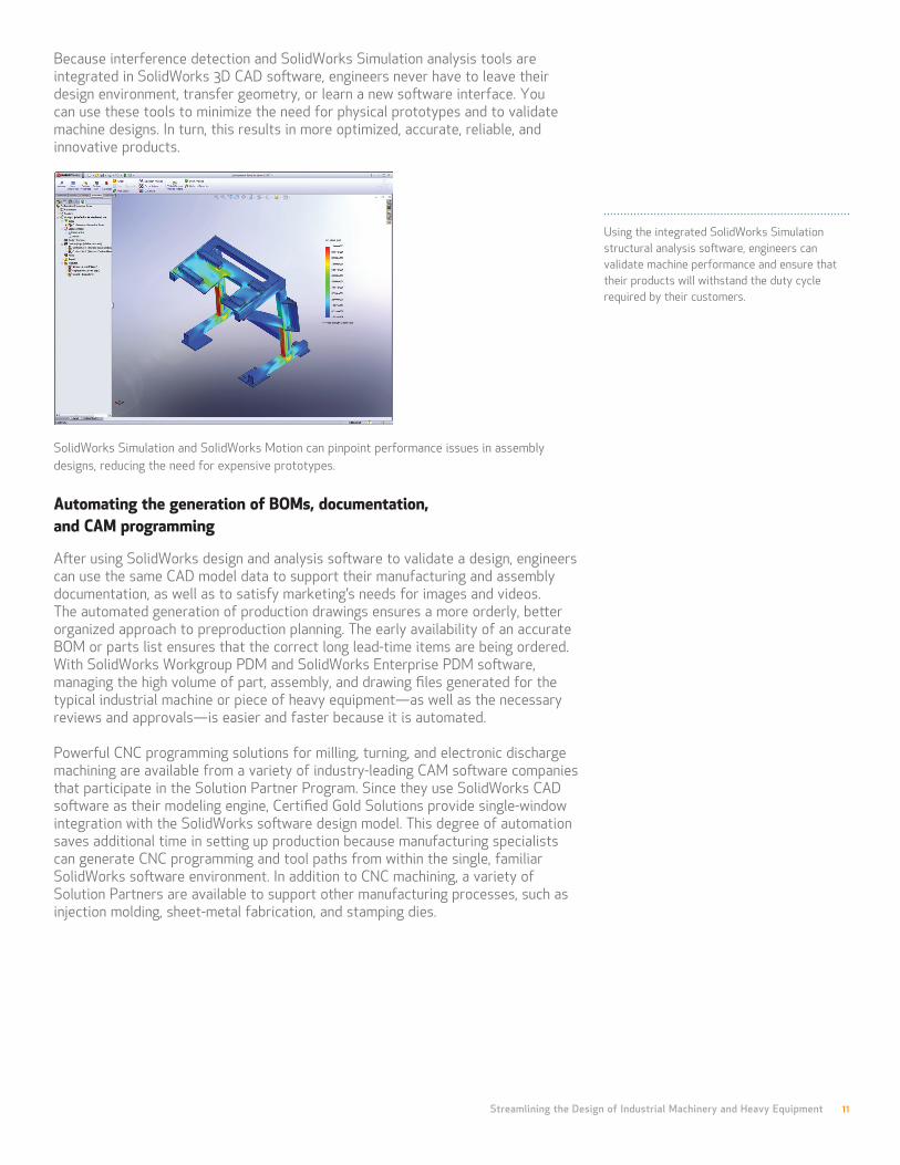
Using the integrated SolidWorks Simulation structural analysis software, engineers can validate machine performance and ensure that their products will withstand the duty cycle required by their customers. With SolidWorks Simulation, you can determine the stress, strain, and deflection of components during operation, helping to identify, resolve, and avoid failures in the field. In addition to rectifying problems by using structural analysis to modify parts and assemblies, you can utilize SolidWorks Simulation to optimize designs and select less expensive or lighter-duty parts, or remove unnecessary material to reduce the cost and weight of a machine.
Streamlining the Design of Industrial Machinery and Heavy Equipment 11
Using the integrated SolidWorks Simulation structural analysis software, engineers can validate machine performance and ensure that their products will withstand the duty cycle required by their customers.
Because interference detection and SolidWorks Simulation analysis tools are integrated in SolidWorks 3D CAD software, engineers never have to leave their design environment, transfer geometry, or learn a new software interface. You can use these tools to minimize the need for physical prototypes and to validate machine designs. In turn, this results in more optimized, accurate, reliable, and innovative products.
SolidWorks Simulation and SolidWorks Motion can pinpoint performance issues in assembly designs, reducing the need for expensive prototypes.
Automating the generation of BOMs, documentation, and CAM programming After using SolidWorks design and analysis software to validate a design, engineers can use the same CAD model data to support their manufacturing and assembly documentation, as well as to satisfy marketing’s needs for images and videos. The automated generation of production drawings ensures a more orderly, better organized approach to preproduction planning. The early availability of an accurate BOM or parts list ensures that the correct long lead-time items are being ordered. With SolidWorks Workgroup PDM and SolidWorks Enterprise PDM software, managing the high volume of part, assembly, and drawing files generated for the typical industrial machine or piece of heavy equipment—as well as the necessary reviews and approvals—is easier and faster because it is automated.
Powerful CNC programming solutions for milling, turning, and electronic discharge machining are available from a variety of industry-leading CAM software companies that participate in the Solution Partner Program. Since they use SolidWorks CAD software as their modeling engine, Certified Gold Solutions provide single-window integration with the SolidWorks software design model. This degree of automation saves additional time in setting up production because manufacturing specialists can generate CNC programming and tool paths from within the single, familiar SolidWorks software environment. In addition to CNC machining, a variety of Solution Partners are available to support other manufacturing processes, such as injection molding, sheet-metal fabrication, and stamping dies.
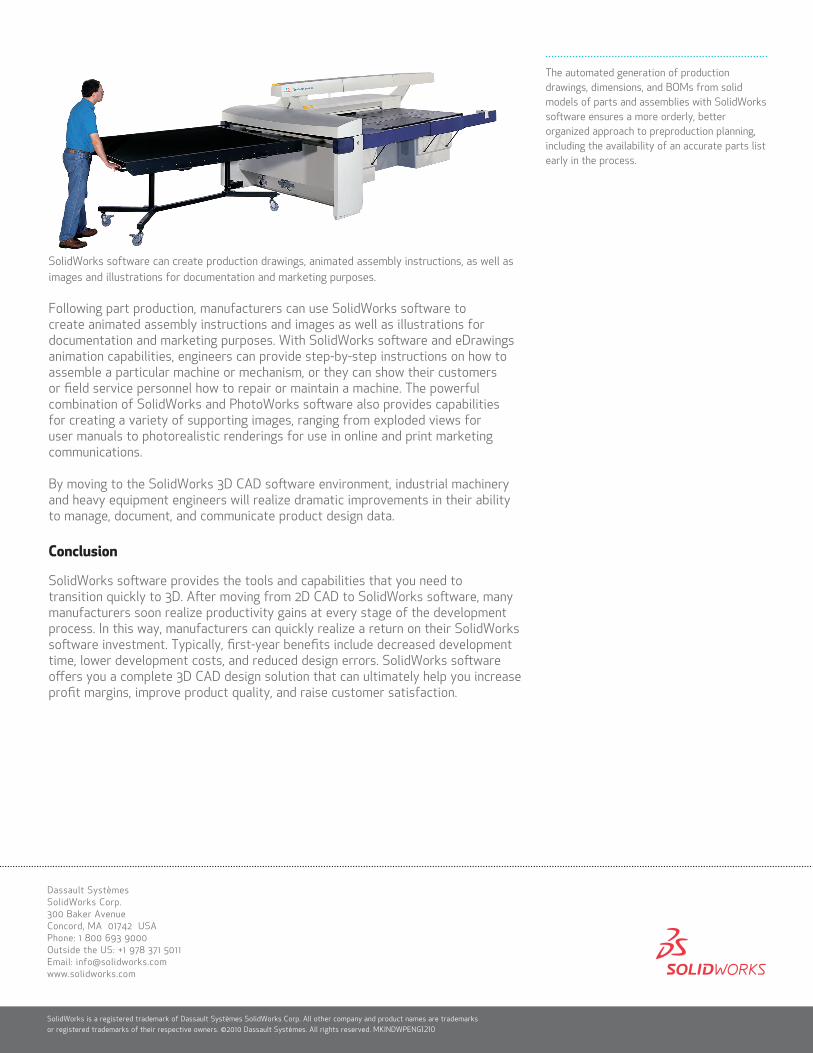
The automated generation of production drawings, dimensions, and BOMs from solid models of parts and assemblies with SolidWorks software ensures a more orderly, better organized approach to preproduction planning, including the availability of an accurate parts list early in the process.
SolidWorks software can create production drawings, animated assembly instructions, as well as images and illustrations for documentation and marketing purposes.
Following part production, manufacturers can use SolidWorks software to create animated assembly instructions and images as well as illustrations for documentation and marketing purposes. With SolidWorks software and eDrawings animation capabilities, engineers can provide step-by-step instructions on how to assemble a particular machine or mechanism, or they can show their customers or field service personnel how to repair or maintain a machine. The powerful combination of SolidWorks and PhotoWorks software also provides capabilities for creating a variety of supporting images, ranging from exploded views for user manuals to photorealistic renderings for use in online and print marketing communications.
By moving to the SolidWorks 3D CAD software environment, industrial machinery and heavy equipment engineers will realize dramatic improvements in their ability to manage, document, and communicate product design data.
Conclusion
SolidWorks software provides the tools and capabilities that you need to transition quickly to 3D. After moving from 2D CAD to SolidWorks software, many manufacturers soon realize productivity gains at every stage of the development process. In this way, manufacturers can quickly realize a return on their SolidWorks software investment. Typically, first-year benefits include decreased development time, lower development costs, and reduced design errors. SolidWorks software offers you a complete 3D CAD design solution that can ultimately help you increase profit margins, improve product quality, and raise customer satisfaction.
SolidWorks is a registered trademark of Dassault Systèmes SolidWorks Corp. All other company and product names are trademarks or registered trademarks of their respective owners. ©2010 Dassault Systèmes. All rights reserved. MKINDWPENG1210
Dassault Systèmes SolidWorks Corp. 300 Baker Avenue Concord, MA 01742 USA Phone: 1 800 693 9000 Outside the US: +1 978 371 5011 Email: [email protected] www.solidworks.com