Embed Size (px)
Citation preview
Gentech Design Center1
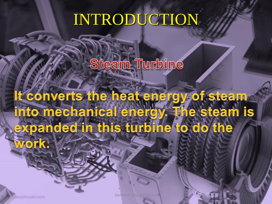
INTRODUCTIONINTRODUCTION
Gentech Design Center 2
Gentech Design Center 3
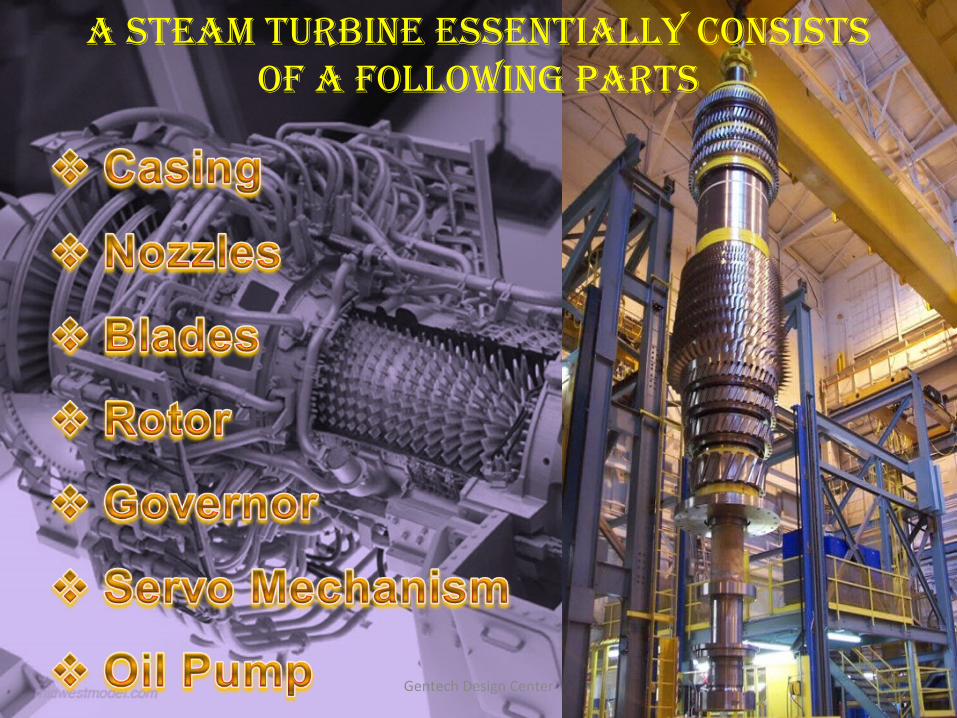
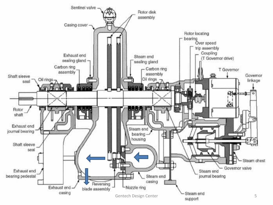
A STEAM TURBINE ESSENTIALLY CONSISTS OF A FOLLOWING PARTS
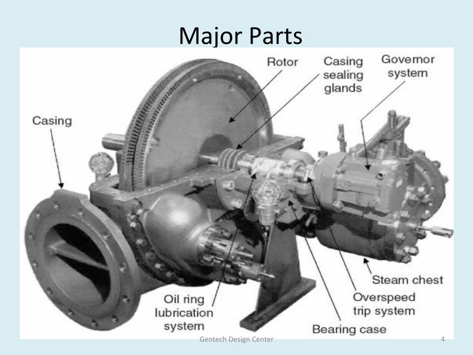
Major Parts
Gentech Design Center 4
Gentech Design Center 5
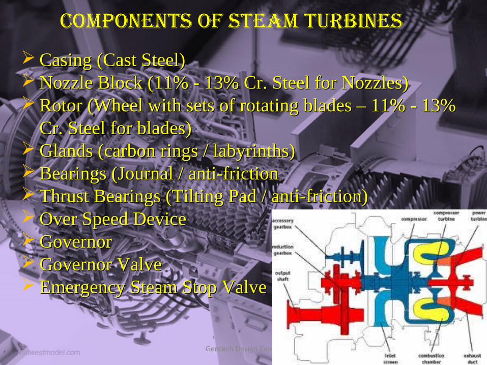
COMPONENTS OF STEAM TURBINES
Casing (Cast Steel)Casing (Cast Steel) Nozzle Block (11% - 13% Cr. Steel for Nozzles)Nozzle Block (11% - 13% Cr. Steel for Nozzles) Rotor (Wheel with sets of rotating blades – 11% - 13% Rotor (Wheel with sets of rotating blades – 11% - 13%
Cr. Steel for blades)Cr. Steel for blades) Glands (carbon rings / labyrinths)Glands (carbon rings / labyrinths) Bearings (Journal / anti-frictionBearings (Journal / anti-friction Thrust Bearings (Tilting Pad / anti-friction)Thrust Bearings (Tilting Pad / anti-friction) Over Speed DeviceOver Speed Device GovernorGovernor Governor ValveGovernor Valve Emergency Steam Stop ValveEmergency Steam Stop Valve
Gentech Design Center 6
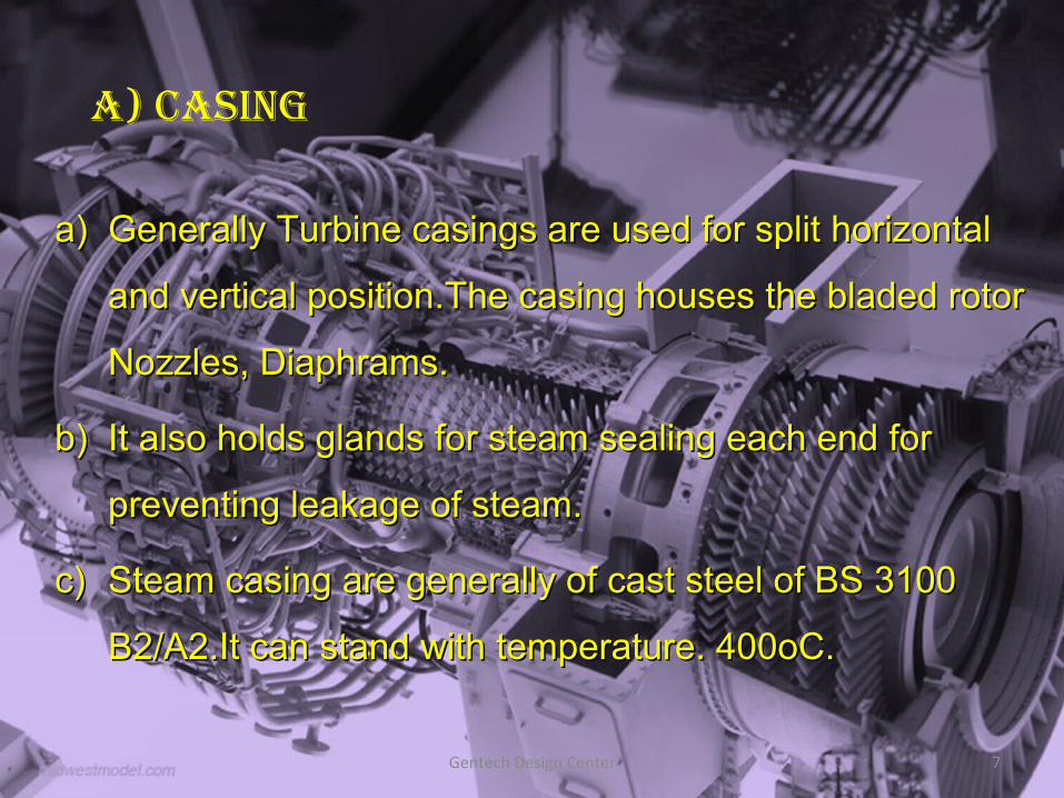
A) CASING
a)a) Generally Turbine casings are used for split horizontal Generally Turbine casings are used for split horizontal
and vertical position.The casing houses the bladed rotor and vertical position.The casing houses the bladed rotor
Nozzles, Diaphrams. Nozzles, Diaphrams.
b)b) It also holds glands for steam sealing each end for It also holds glands for steam sealing each end for
preventing leakage of steam.preventing leakage of steam.
c)c) Steam casing are generally of cast steel of BS 3100 Steam casing are generally of cast steel of BS 3100
B2/A2.It can stand with temperature. 400oC.B2/A2.It can stand with temperature. 400oC.
Gentech Design Center 7
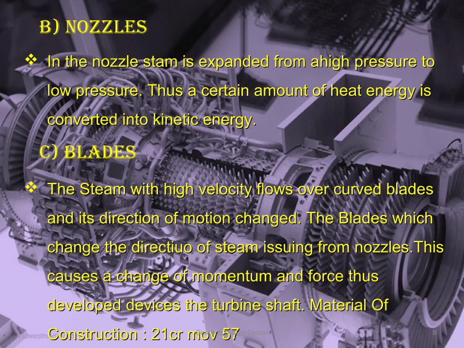
B) NOzzLES
In the nozzle stam is expanded from ahigh pressure to In the nozzle stam is expanded from ahigh pressure to
low pressure. Thus a certain amount of heat energy is low pressure. Thus a certain amount of heat energy is
converted into kinetic energy.converted into kinetic energy.
C) BLAdES
The Steam with high velocity flows over curved blades The Steam with high velocity flows over curved blades
and its direction of motion changed. The Blades which and its direction of motion changed. The Blades which
change the directiuo of steam issuing from nozzles.This change the directiuo of steam issuing from nozzles.This
causes a change of momentum and force thus causes a change of momentum and force thus
developed devices the turbine shaft. Material Of developed devices the turbine shaft. Material Of
Construction : 21cr mov 57Construction : 21cr mov 57Gentech Design Center 8
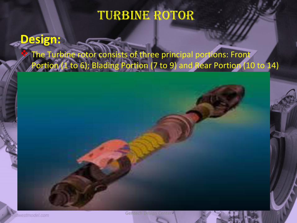
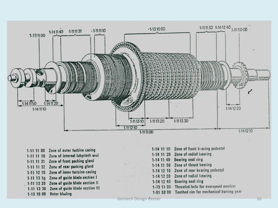
TURBINE ROTOR
Design: The Turbine rotor consists of three principal portions: Front
Portion (1 to 6); Blading Portion (7 to 9) and Rear Portion (10 to 14)
Gentech Design Center 9
Gentech Design Center 10
d) governor
Governor is a device, Which senses the speed of Governor is a device, Which senses the speed of
turbine and controls the steam to the turbine to maintain turbine and controls the steam to the turbine to maintain
the speed at a desired level to meet changes in load the speed at a desired level to meet changes in load
(or) steam flow.(or) steam flow.
Gentech Design Center 11
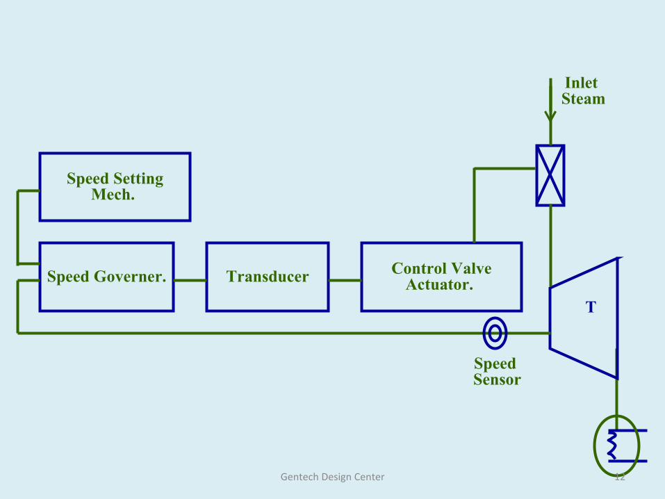
Speed Setting Mech.
Speed Governer. Transducer Control Valve Actuator.
Speed Sensor
T
Inlet Steam
Gentech Design Center 12
governor
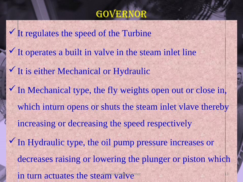
It regulates the speed of the Turbine
It operates a built in valve in the steam inlet line
It is either Mechanical or Hydraulic
In Mechanical type, the fly weights open out or close in,
which inturn opens or shuts the steam inlet vlave thereby
increasing or decreasing the speed respectively
In Hydraulic type, the oil pump pressure increases or
decreases raising or lowering the plunger or piston which
in turn actuates the steam valveGentech Design Center 13
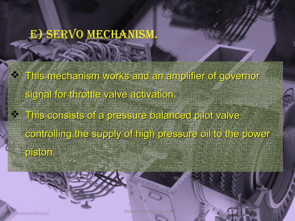
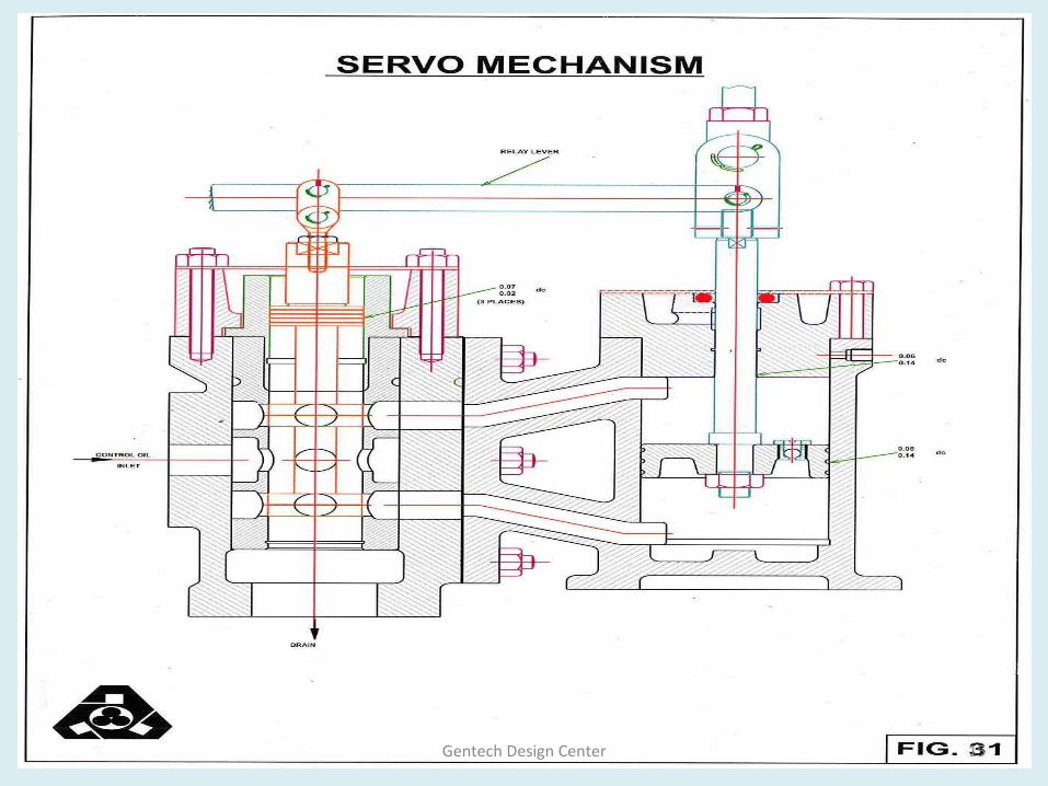
e) Servo mechaniSm.
This mechanism works and an amplifier of governor This mechanism works and an amplifier of governor
signal for throttle valve activation.signal for throttle valve activation.
This consists of a pressure balanced pilot valve This consists of a pressure balanced pilot valve
controlling the supply of high pressure oil to the power controlling the supply of high pressure oil to the power
piston.piston.
Gentech Design Center 14
Gentech Design Center 15
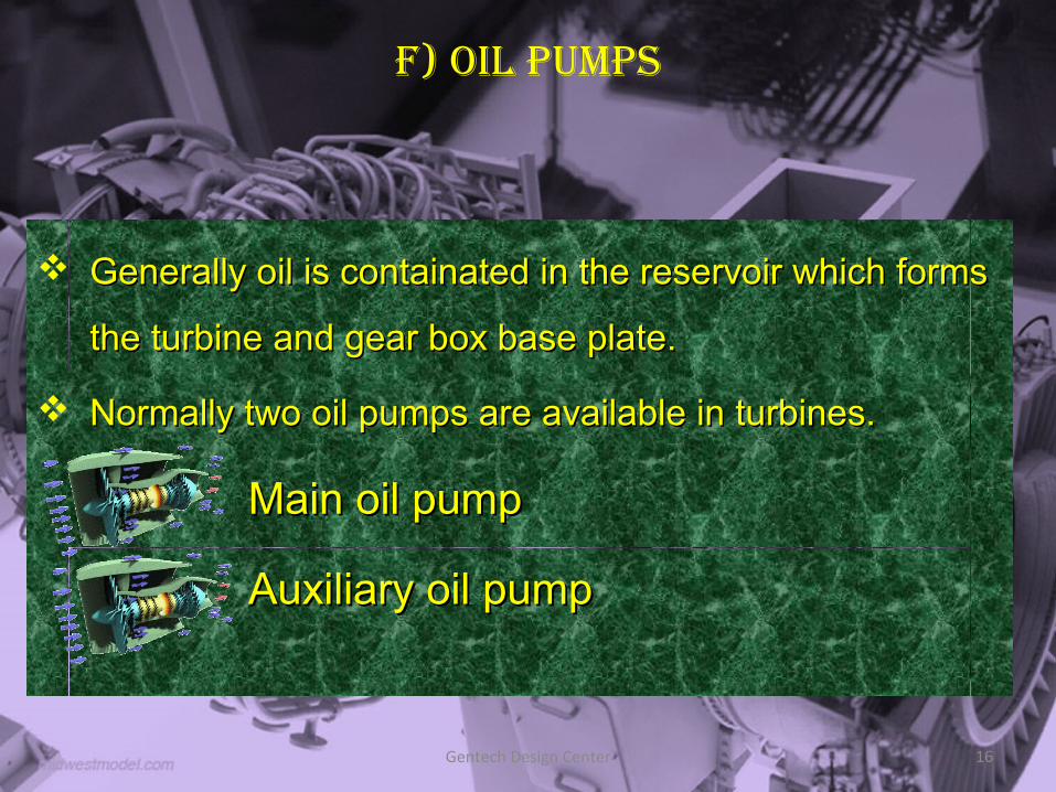
F) oiL pumpS
Generally oil is containated in the reservoir which forms Generally oil is containated in the reservoir which forms
the turbine and gear box base plate.the turbine and gear box base plate.
Normally two oil pumps are available in turbines.Normally two oil pumps are available in turbines.
Main oil pumpMain oil pump
Auxiliary oil pumpAuxiliary oil pump
Gentech Design Center 16
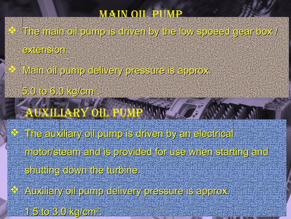
main oiL pump The main oil pump is driven by the low spoeed gear box / The main oil pump is driven by the low spoeed gear box /
extension.extension.
Main oil pump delivery pressure is approx.Main oil pump delivery pressure is approx.
5.0 to 6.0 kg/cm5.0 to 6.0 kg/cm22..
auxiLiary oiL pump
The auxiliary oil pump is driven by an electrical The auxiliary oil pump is driven by an electrical
motor/steam and is provided for use when starting and motor/steam and is provided for use when starting and
shutting down the turbine.shutting down the turbine.
Auxiliary oil pump delivery pressure is approx.Auxiliary oil pump delivery pressure is approx.
1.5 to 3.0 kg/cm1.5 to 3.0 kg/cm22.. Gentech Design Center 17
TypeS oF Turbine
A. Impulse Turbine
The steam pressure at the outlet side of the blade is equal to inlet side such a turbine is termed as impulse Turbine.
B. Reaction Turbine
The steam pressure at the outlet side of the blade is less than at inlet side of the blade.
A. Impulse Turbine
The steam pressure at the outlet side of the blade is equal to inlet side such a turbine is termed as impulse Turbine.
B. Reaction Turbine
The steam pressure at the outlet side of the blade is less than at inlet side of the blade.
Gentech Design Center 18
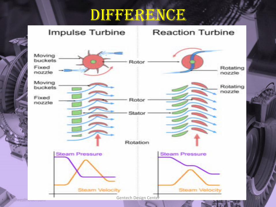
diFFerence
Gentech Design Center 19
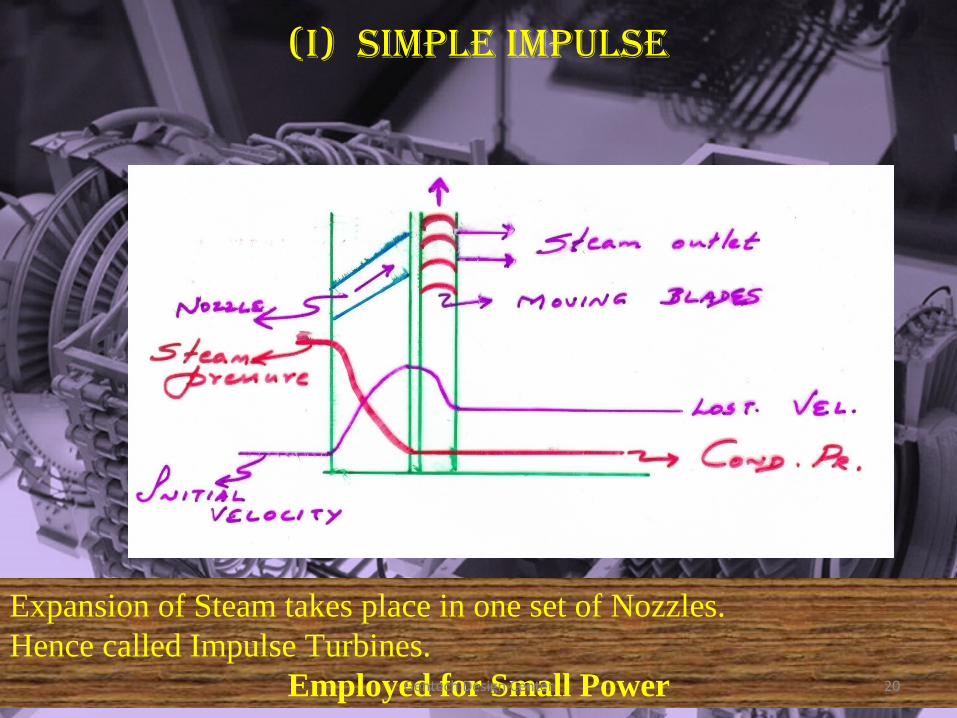
(i) SimpLe impuLSe
Expansion of Steam takes place in one set of Nozzles. Hence called Impulse Turbines.
Employed for Small PowerGentech Design Center 20
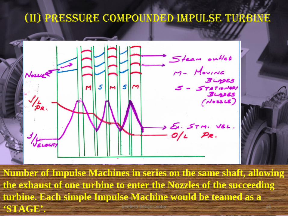
(II) PRESSURE COMPOUNDED IMPULSE TURBINE
Number of Impulse Machines in series on the same shaft, allowing the exhaust of one turbine to enter the Nozzles of the succeeding turbine. Each simple Impulse Machine would be teamed as a ‘STAGE’. Gentech Design Center 21
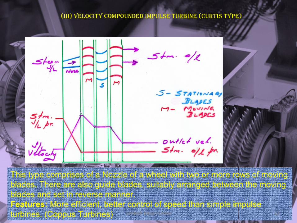
(III) VELOCITY COMPOUNDED IMPULSE TURBINE (CURTIS TYPE)
This type comprises of a Nozzle of a wheel with two or more rows of moving blades. There are also guide blades, suitably arranged between the moving blades and set in reverse manner.Features: More efficient, better control of speed than simple impulse turbines. (Coppus Turbines) Gentech Design Center 22
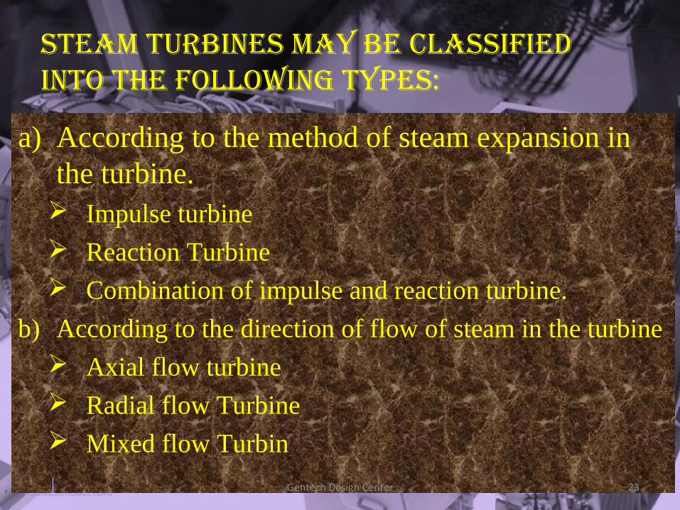
STEaM TURBINES MaY BE CLaSSIfIED INTO ThE fOLLOwINg TYPES:
a) According to the method of steam expansion in the turbine. Impulse turbine Reaction Turbine Combination of impulse and reaction turbine.
b) According to the direction of flow of steam in the turbine Axial flow turbine Radial flow Turbine Mixed flow Turbin
Gentech Design Center 23
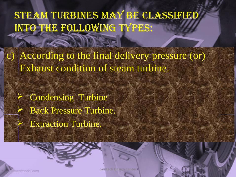
STEaM TURBINES MaY BE CLaSSIfIED INTO ThE fOLLOwINg TYPES:
c) According to the final delivery pressure (or) Exhaust condition of steam turbine.
Condensing Turbine Back Pressure Turbine. Extraction Turbine.
Gentech Design Center 24
STEaM TURBINES MaY BE CLaSSIfIED INTO ThE fOLLOwINg TYPES:
d) According to the number of stages of turbines.
Single stage turbine. Multi stage turbine.
d) According to the pressure of steam turbines.
Low pressure turbine. Medium pressure turbine. High pressure turbine.
Gentech Design Center 25
SafETY DEVICES (MEChaNICaL DEVICES)
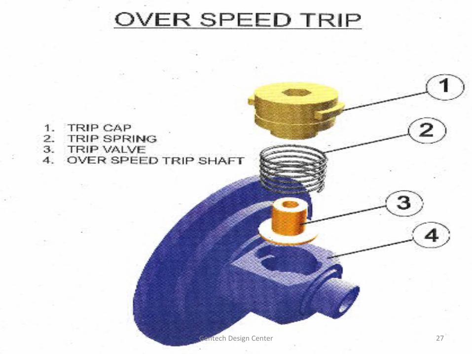
1. Over speed Trip
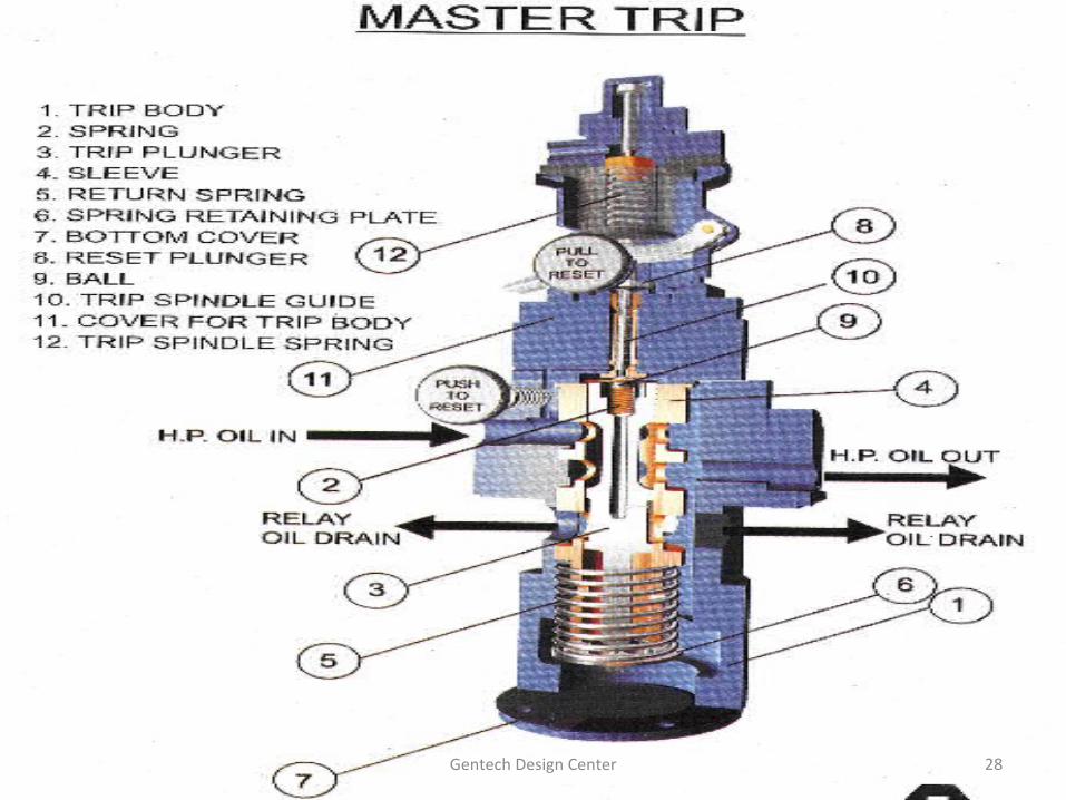
2. Master trip
3. LP Trip
Gentech Design Center 26
Gentech Design Center 27
Gentech Design Center 28
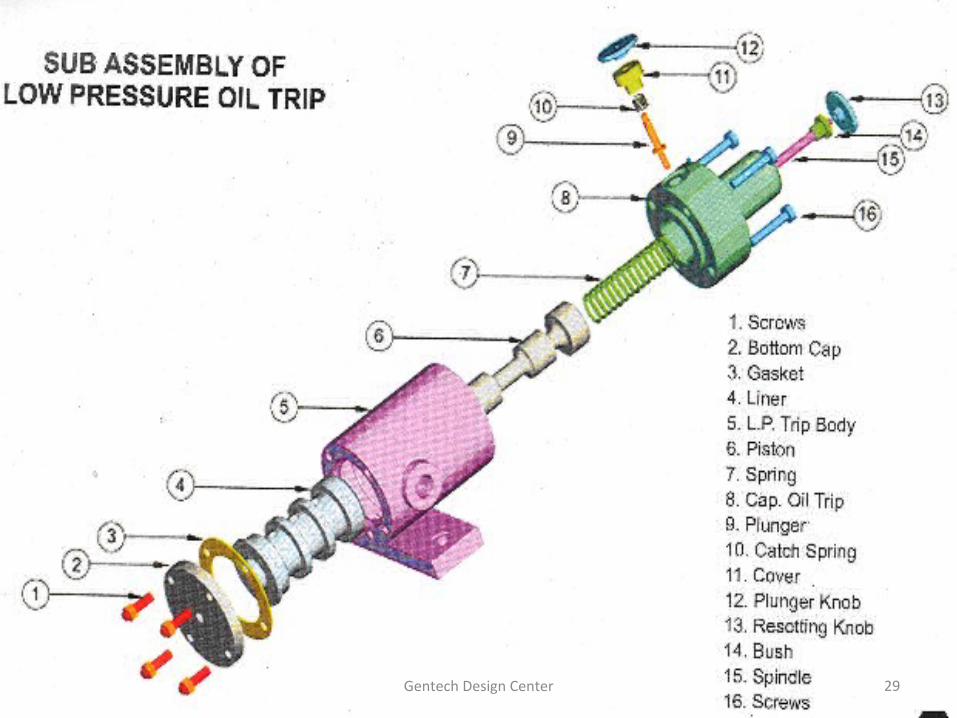
Gentech Design Center 29
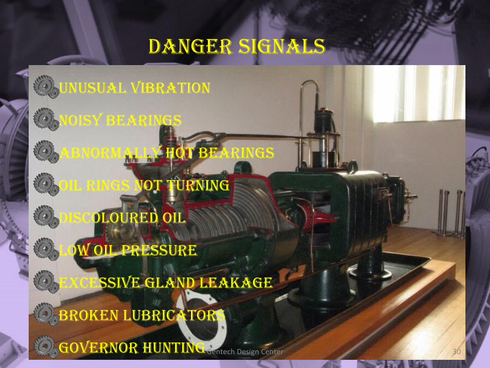
DaNgER SIgNaLS
UNUSUaL VIBRaTION
NOISY BEaRINgS
aBNORMaLLY hOT BEaRINgS
OIL RINgS NOT TURNINg
DISCOLOURED OIL
LOw OIL PRESSURE
ExCESSIVE gLaND LEakagE
BROkEN LUBRICaTORS
gOVERNOR hUNTINgGentech Design Center 30
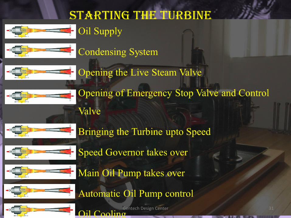
Starting the turbine
Gentech Design Center 31
Protection SyStem
Special Purpose Turbines
Low Lub. Oil Pressure Trip
High Brg. Temp. Trip
High Vibn. Trip
High Axial Disp. Trip
Const. Speed Governor
Relief Valve in Exhaust
Gentech Design Center 32
What to check for in running turbineS
Noise Levels
Leakage from Glands
Vibration at Bearing Housings
Bearing Temperatures
Movement of Oil Rings of Sleeve Bearings
Governor Oil Level (for Oil Relay Governors)
Gentech Design Center 33
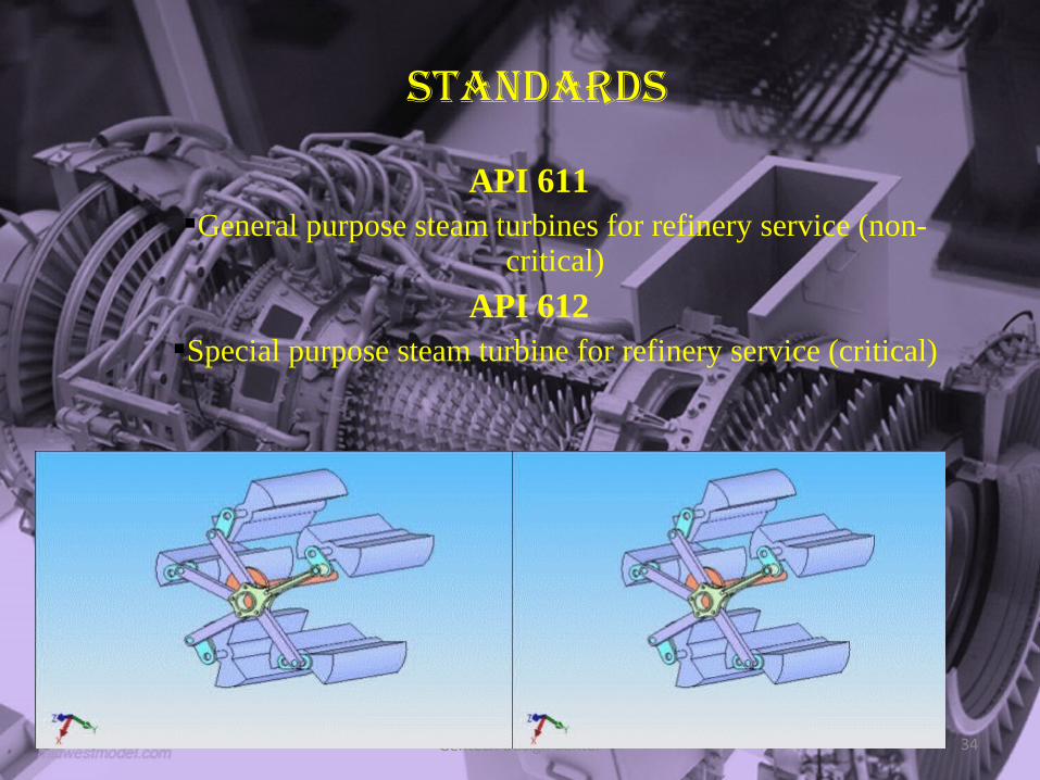
StandardS
API 611General purpose steam turbines for refinery service (non-
critical)
API 612Special purpose steam turbine for refinery service (critical)
Gentech Design Center 34
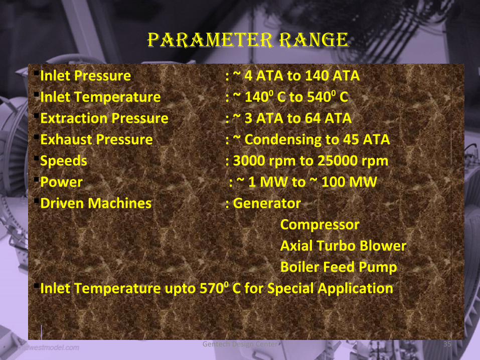
Parameter range
Gentech Design Center 35
Inlet Pressure : ~ 4 ATA to 140 ATAInlet Temperature : ~ 1400 C to 5400 CExtraction Pressure : ~ 3 ATA to 64 ATAExhaust Pressure : ~ Condensing to 45 ATASpeeds : 3000 rpm to 25000 rpmPower : ~ 1 MW to ~ 100 MWDriven Machines : Generator Compressor Axial Turbo Blower Boiler Feed PumpInlet Temperature upto 5700 C for Special Application
Gentech Design Center 36
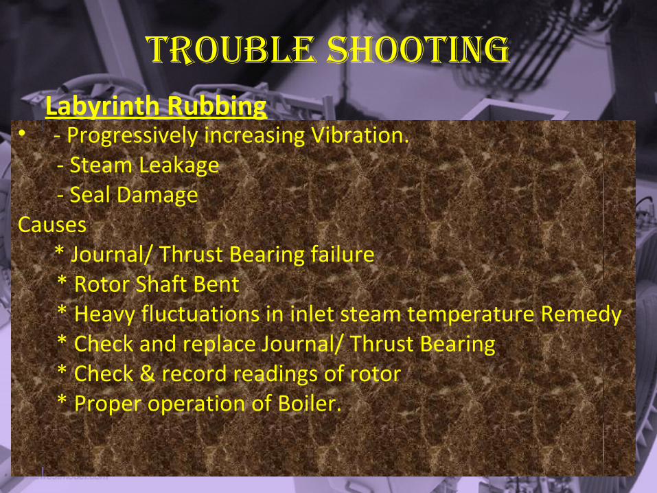
trouble Shooting
• - Progressively increasing Vibration. - Steam Leakage - Seal DamageCauses * Journal/ Thrust Bearing failure
* Rotor Shaft Bent * Heavy fluctuations in inlet steam temperature Remedy * Check and replace Journal/ Thrust Bearing * Check & record readings of rotor * Proper operation of Boiler.
Labyrinth Rubbing
Gentech Design Center 37
trouble Shooting
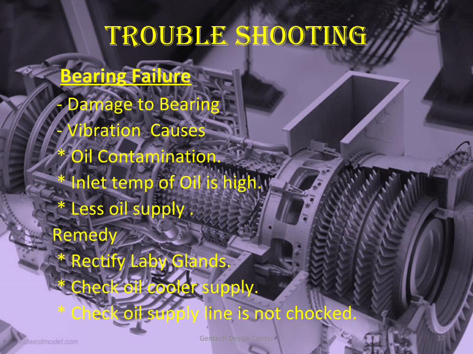
- Damage to Bearing - Vibration Causes * Oil Contamination. * Inlet temp of Oil is high. * Less oil supply .Remedy * Rectify Laby Glands. * Check oil cooler supply. * Check oil supply line is not chocked.
Bearing Failure
Gentech Design Center 38
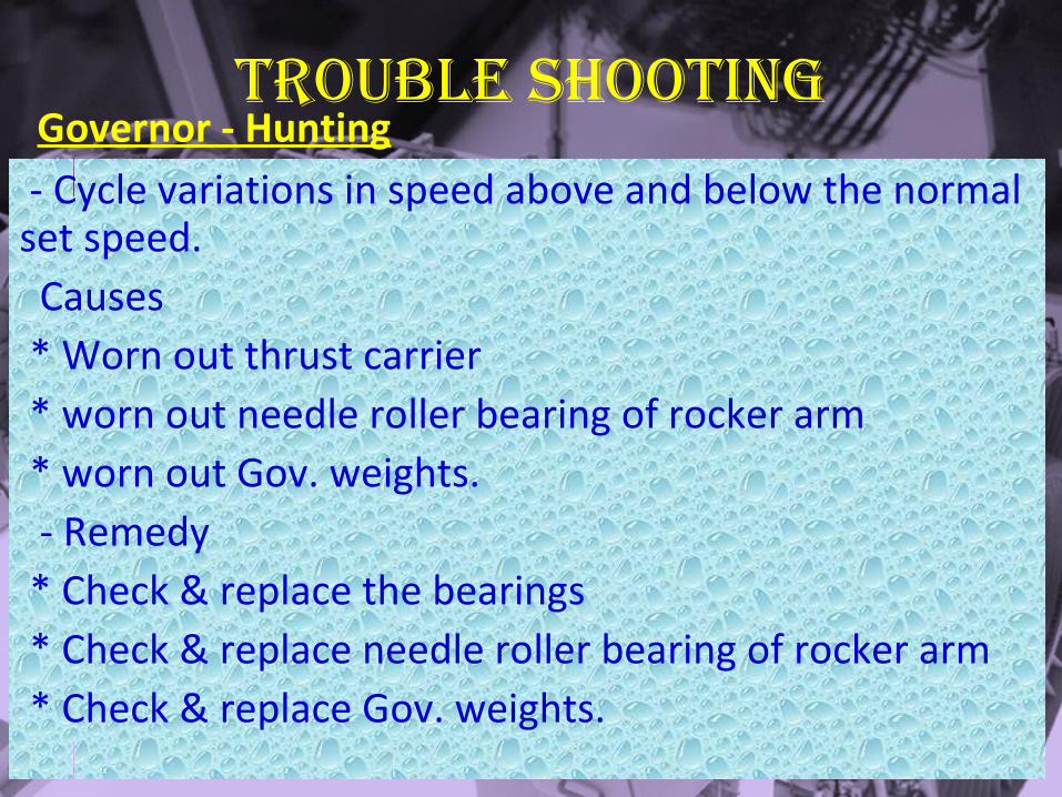
trouble ShootingGovernor - Hunting
- Cycle variations in speed above and below the normal set speed. Causes * Worn out thrust carrier * worn out needle roller bearing of rocker arm * worn out Gov. weights. - Remedy * Check & replace the bearings * Check & replace needle roller bearing of rocker arm * Check & replace Gov. weights.
Gentech Design Center 39


