Embed Size (px)
DESCRIPTION
Solucionario Incropera Transferencia de calor Ch01
Citation preview
PROBLEM 1.1 KNOWN: Heat rate, q, through one-dimensional wall of area A, thickness L, thermal conductivity k and inner temperature, T1. FIND: The outer temperature of the wall, T2. SCHEMATIC:
ASSUMPTIONS: (1) One-dimensional conduction in the x-direction, (2) Steady-state conditions, (3) Constant properties. ANALYSIS: The rate equation for conduction through the wall is given by Fourier’s law,
q q q A = -kdT
dxA = kA
T T
Lcond x x1 2= = ′′ ⋅ ⋅
−.
Solving for T2 gives
T Tq L
kA2 1cond= − .
Substituting numerical values, find
T C -3000W 0.025m
0.2W / m K 10m2 2= ×⋅ ×
415$
T C -37.5 C2 = 415$ $
T C.2 = 378$ <
COMMENTS: Note direction of heat flow and fact that T2 must be less than T1.
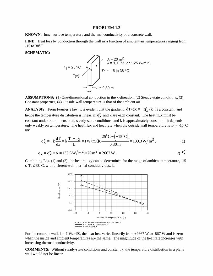
PROBLEM 1.2 KNOWN: Inner surface temperature and thermal conductivity of a concrete wall. FIND: Heat loss by conduction through the wall as a function of ambient air temperatures ranging from -15 to 38°C. SCHEMATIC:
ASSUMPTIONS: (1) One-dimensional conduction in the x-direction, (2) Steady-state conditions, (3) Constant properties, (4) Outside wall temperature is that of the ambient air. ANALYSIS: From Fourier’s law, it is evident that the gradient, xdT dx q k′′= − , is a constant, and
hence the temperature distribution is linear, if xq′′ and k are each constant. The heat flux must be constant under one-dimensional, steady-state conditions; and k is approximately constant if it depends only weakly on temperature. The heat flux and heat rate when the outside wall temperature is T2 = -15°C are
( ) 21 2
x
25 C 15 CdT T Tq k k 1W m K 133.3W m
dx L 0.30m
− −−′′ = − = = ⋅ =$ $
. (1)
2 2x xq q A 133.3W m 20m 2667 W′′= × = × = . (2) <
Combining Eqs. (1) and (2), the heat rate qx can be determined for the range of ambient temperature, -15 ≤ T2 ≤ 38°C, with different wall thermal conductivities, k.
-20 -10 0 10 20 30 40
Ambient air temperature, T2 (C)
-1500
-500
500
1500
2500
3500
Hea
t los
s, q
x (W
)
Wall thermal conductivity, k = 1.25 W/m.Kk = 1 W/m.K, concrete wallk = 0.75 W/m.K
For the concrete wall, k = 1 W/m⋅K, the heat loss varies linearily from +2667 W to -867 W and is zero when the inside and ambient temperatures are the same. The magnitude of the heat rate increases with increasing thermal conductivity. COMMENTS: Without steady-state conditions and constant k, the temperature distribution in a plane wall would not be linear.
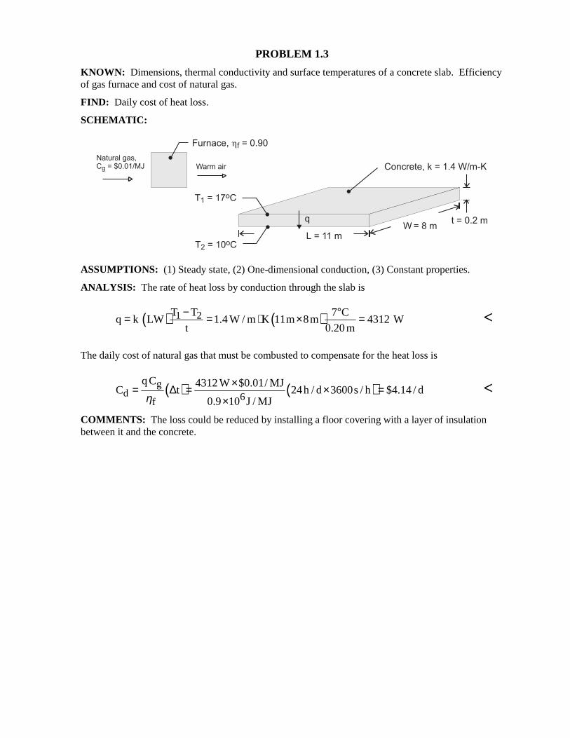
PROBLEM 1.3 KNOWN: Dimensions, thermal conductivity and surface temperatures of a concrete slab. Efficiency of gas furnace and cost of natural gas. FIND: Daily cost of heat loss. SCHEMATIC:
ASSUMPTIONS: (1) Steady state, (2) One-dimensional conduction, (3) Constant properties. ANALYSIS: The rate of heat loss by conduction through the slab is
( ) ( )1 2T T 7 Cq k LW 1.4 W / m K 11m 8m 4312 W
t 0.20m
− °= = ⋅ × = <
The daily cost of natural gas that must be combusted to compensate for the heat loss is
( ) ( )gd 6f
q C 4312 W $0.01/ MJC t 24h / d 3600s / h $4.14 / d
0.9 10 J / MJη×= ∆ = × =
× <
COMMENTS: The loss could be reduced by installing a floor covering with a layer of insulation between it and the concrete.
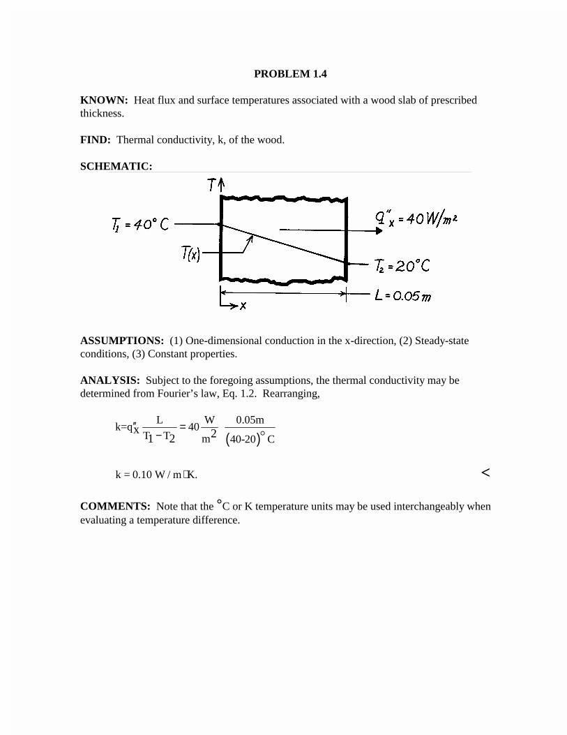
PROBLEM 1.4
KNOWN: Heat flux and surface temperatures associated with a wood slab of prescribedthickness.
FIND: Thermal conductivity, k, of the wood.
SCHEMATIC:
ASSUMPTIONS: (1) One-dimensional conduction in the x-direction, (2) Steady-stateconditions, (3) Constant properties.
ANALYSIS: Subject to the foregoing assumptions, the thermal conductivity may bedetermined from Fourier’s law, Eq. 1.2. Rearranging,
( )L W 0.05m
k=q 40 T T m 40-20 C
x 21 2′′ =
−
k = 0.10 W / m K.⋅ <
COMMENTS: Note that the °C or K temperature units may be used interchangeably whenevaluating a temperature difference.
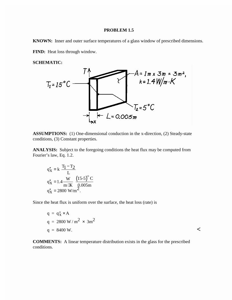
PROBLEM 1.5
KNOWN: Inner and outer surface temperatures of a glass window of prescribed dimensions.
FIND: Heat loss through window.
SCHEMATIC:
ASSUMPTIONS: (1) One-dimensional conduction in the x-direction, (2) Steady-stateconditions, (3) Constant properties.
ANALYSIS: Subject to the foregoing conditions the heat flux may be computed fromFourier’s law, Eq. 1.2.
( )
T Tq k
L15-5 CW
q 1.4 m K 0.005m
q 2800 W/m .
1 2x
x2
x
−′′ =
′′ =⋅
′′ =
Since the heat flux is uniform over the surface, the heat loss (rate) is
q = qx A
q = 2800 W / m2 3m2
′′ ×
×
q = 8400 W. <
COMMENTS: A linear temperature distribution exists in the glass for the prescribedconditions.
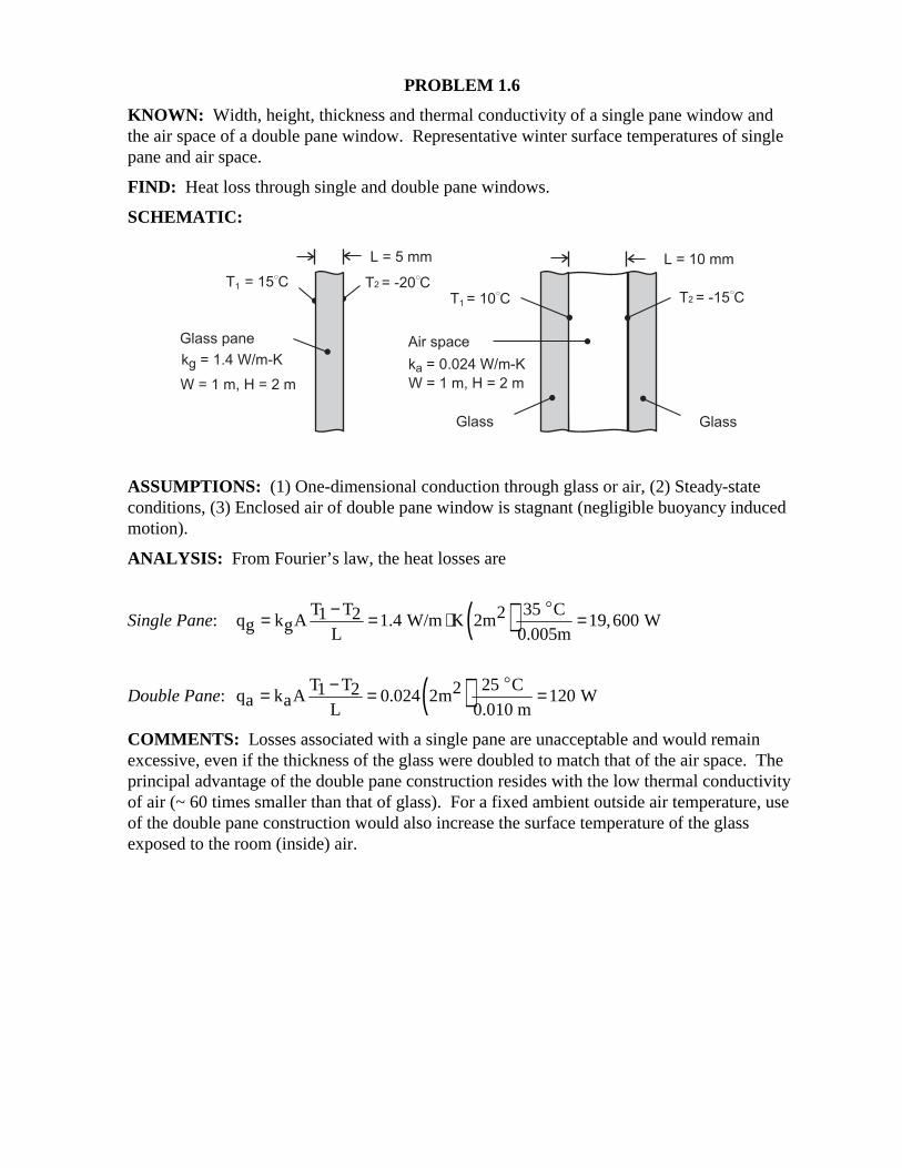
PROBLEM 1.6 KNOWN: Width, height, thickness and thermal conductivity of a single pane window and the air space of a double pane window. Representative winter surface temperatures of single pane and air space. FIND: Heat loss through single and double pane windows. SCHEMATIC:
ASSUMPTIONS: (1) One-dimensional conduction through glass or air, (2) Steady-state conditions, (3) Enclosed air of double pane window is stagnant (negligible buoyancy induced motion). ANALYSIS: From Fourier’s law, the heat losses are
Single Pane: ( )T T 35 C21 2q k A 1.4 W/m K 2m 19,600 Wg g L 0.005m
−= = ⋅ =$
Double Pane: ( )T T 25 C21 2q k A 0.024 2m 120 Wa a L 0.010 m
−= = =$
COMMENTS: Losses associated with a single pane are unacceptable and would remain excessive, even if the thickness of the glass were doubled to match that of the air space. The principal advantage of the double pane construction resides with the low thermal conductivity of air (~ 60 times smaller than that of glass). For a fixed ambient outside air temperature, use of the double pane construction would also increase the surface temperature of the glass exposed to the room (inside) air.
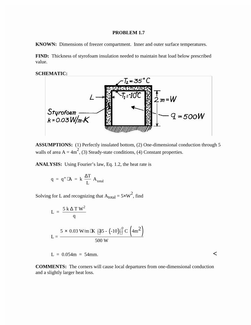
PROBLEM 1.7
KNOWN: Dimensions of freezer compartment. Inner and outer surface temperatures.
FIND: Thickness of styrofoam insulation needed to maintain heat load below prescribedvalue.
SCHEMATIC:
ASSUMPTIONS: (1) Perfectly insulated bottom, (2) One-dimensional conduction through 5
walls of area A = 4m2, (3) Steady-state conditions, (4) Constant properties.
ANALYSIS: Using Fourier’s law, Eq. 1.2, the heat rate is
q = q A = k T
L Atotal′′ ⋅ ∆
Solving for L and recognizing that Atotal = 5×W2, find
L = 5 k T W
q
2∆
( ) ( )5 0.03 W/m K 35 - -10 C 4mL =
500 W
2 × ⋅
L = 0.054m = 54mm. <
COMMENTS: The corners will cause local departures from one-dimensional conductionand a slightly larger heat loss.
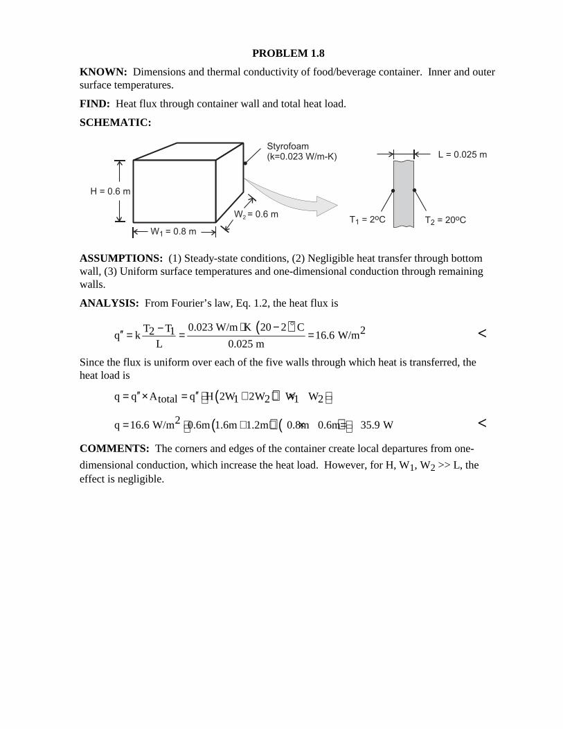
PROBLEM 1.8 KNOWN: Dimensions and thermal conductivity of food/beverage container. Inner and outer surface temperatures. FIND: Heat flux through container wall and total heat load. SCHEMATIC:
ASSUMPTIONS: (1) Steady-state conditions, (2) Negligible heat transfer through bottom wall, (3) Uniform surface temperatures and one-dimensional conduction through remaining walls. ANALYSIS: From Fourier’s law, Eq. 1.2, the heat flux is
( )0.023 W/m K 20 2 CT T 22 1q k 16.6 W/m
L 0.025 m
⋅ −−′′ = = =$
<
Since the flux is uniform over each of the five walls through which heat is transferred, the heat load is ( )q q A q H 2W 2W W Wtotal 1 2 1 2′′ ′′ = × = + + ×
( ) ( )2q 16.6 W/m 0.6m 1.6m 1.2m 0.8m 0.6m 35.9 W = + + × = < COMMENTS: The corners and edges of the container create local departures from one-
dimensional conduction, which increase the heat load. However, for H, W1, W2 >> L, the effect is negligible.
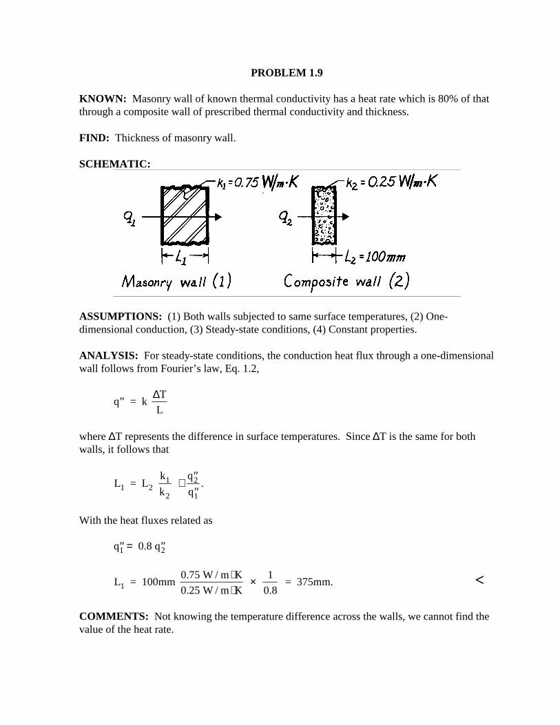
PROBLEM 1.9 KNOWN: Masonry wall of known thermal conductivity has a heat rate which is 80% of that through a composite wall of prescribed thermal conductivity and thickness. FIND: Thickness of masonry wall. SCHEMATIC:
ASSUMPTIONS: (1) Both walls subjected to same surface temperatures, (2) One-dimensional conduction, (3) Steady-state conditions, (4) Constant properties. ANALYSIS: For steady-state conditions, the conduction heat flux through a one-dimensional wall follows from Fourier’s law, Eq. 1.2,
′′q = k T
L
∆
where ∆T represents the difference in surface temperatures. Since ∆T is the same for both walls, it follows that
L = L k
k
q
q1 21
2
2
1
⋅′′′′
.
With the heat fluxes related as ′′ = ′′q 0.8 q1 2
L = 100mm 0.75 W / m K
0.25 W / m K
1
0.8 = 375mm.1
⋅⋅
× <
COMMENTS: Not knowing the temperature difference across the walls, we cannot find the value of the heat rate.
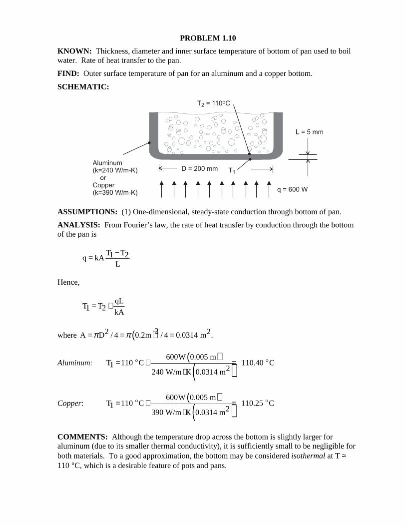
PROBLEM 1.10 KNOWN: Thickness, diameter and inner surface temperature of bottom of pan used to boil water. Rate of heat transfer to the pan. FIND: Outer surface temperature of pan for an aluminum and a copper bottom. SCHEMATIC:
ASSUMPTIONS: (1) One-dimensional, steady-state conduction through bottom of pan. ANALYSIS: From Fourier’s law, the rate of heat transfer by conduction through the bottom of the pan is
T T1 2q kA
L
−=
Hence,
qL
T T1 2 kA= +
where ( )22 2A D / 4 0.2m / 4 0.0314 m .π π= = =
Aluminum: ( )
( )600W 0.005 m
T 110 C 110.40 C1 2240 W/m K 0.0314 m= + =
⋅$ $
Copper: ( )
( )600W 0.005 m
T 110 C 110.25 C1 2390 W/m K 0.0314 m= + =
⋅$ $
COMMENTS: Although the temperature drop across the bottom is slightly larger for aluminum (due to its smaller thermal conductivity), it is sufficiently small to be negligible for both materials. To a good approximation, the bottom may be considered isothermal at T ≈ 110 °C, which is a desirable feature of pots and pans.
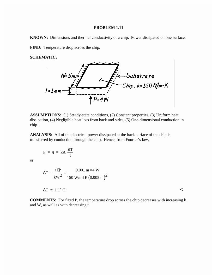
PROBLEM 1.11
KNOWN: Dimensions and thermal conductivity of a chip. Power dissipated on one surface.
FIND: Temperature drop across the chip.
SCHEMATIC:
ASSUMPTIONS: (1) Steady-state conditions, (2) Constant properties, (3) Uniform heatdissipation, (4) Negligible heat loss from back and sides, (5) One-dimensional conduction inchip.
ANALYSIS: All of the electrical power dissipated at the back surface of the chip istransferred by conduction through the chip. Hence, from Fourier’s law,
P = q = kA T
t
∆
or
( )t P 0.001 m 4 W
T = kW 150 W/m K 0.005 m2 2
⋅ ×∆ =⋅
∆T = 1.1 C.$ <
COMMENTS: For fixed P, the temperature drop across the chip decreases with increasing kand W, as well as with decreasing t.
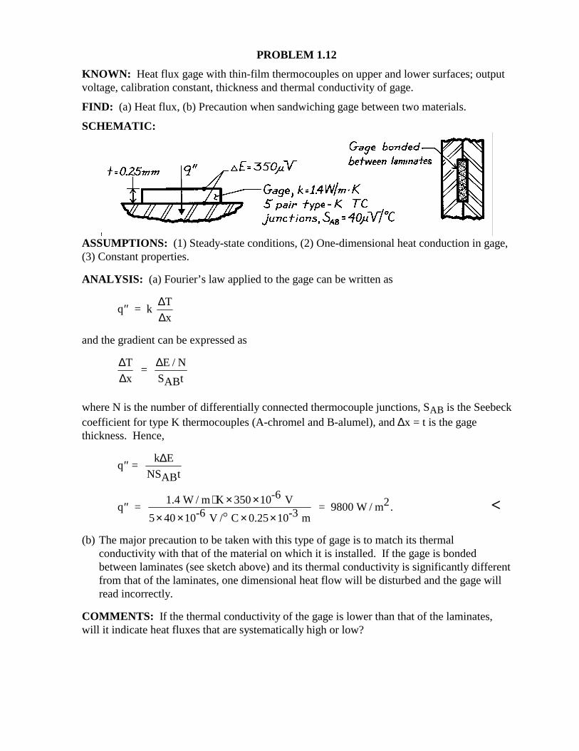
PROBLEM 1.12 KNOWN: Heat flux gage with thin-film thermocouples on upper and lower surfaces; output voltage, calibration constant, thickness and thermal conductivity of gage. FIND: (a) Heat flux, (b) Precaution when sandwiching gage between two materials. SCHEMATIC:
ASSUMPTIONS: (1) Steady-state conditions, (2) One-dimensional heat conduction in gage, (3) Constant properties.
ANALYSIS: (a) Fourier’s law applied to the gage can be written as
′′q = k T
x
∆∆
and the gradient can be expressed as
∆∆
∆T
x =
E / N
SABt
where N is the number of differentially connected thermocouple junctions, SAB is the Seebeck coefficient for type K thermocouples (A-chromel and B-alumel), and ∆x = t is the gage thickness. Hence,
′′q = k E
NSABt
∆
′′ ⋅ × ×× × × ×
q = 1.4 W / m K 350 10-6 V
5 40 10-6 V / C 0.25 10-3 m = 9800 W / m2
$. <
(b) The major precaution to be taken with this type of gage is to match its thermal conductivity with that of the material on which it is installed. If the gage is bonded between laminates (see sketch above) and its thermal conductivity is significantly different from that of the laminates, one dimensional heat flow will be disturbed and the gage will read incorrectly.
COMMENTS: If the thermal conductivity of the gage is lower than that of the laminates, will it indicate heat fluxes that are systematically high or low?
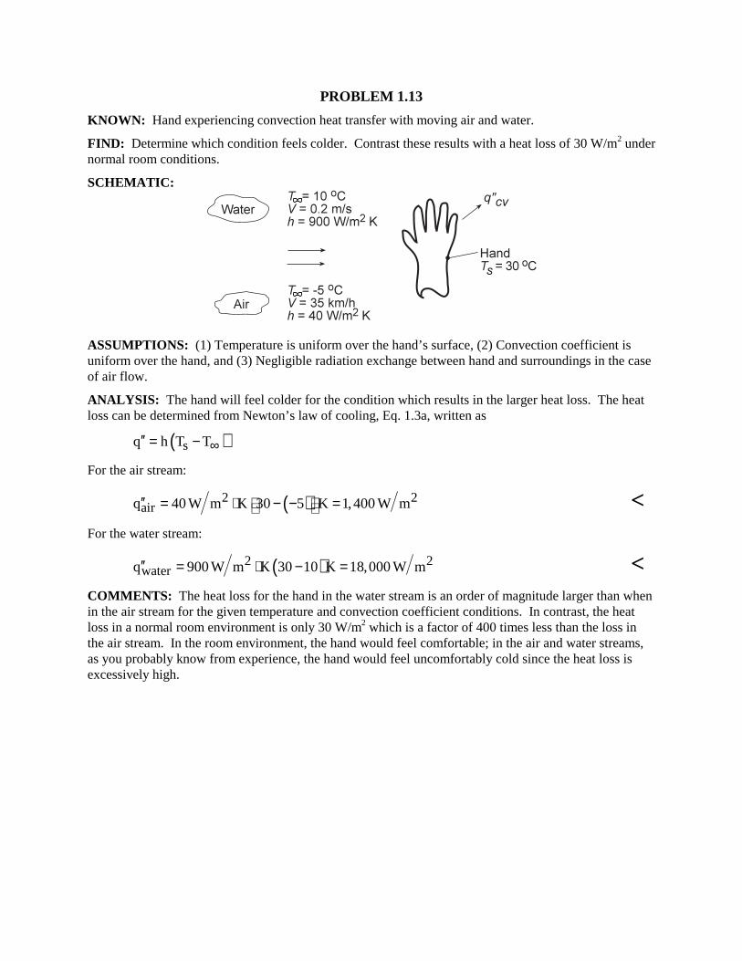
PROBLEM 1.13 KNOWN: Hand experiencing convection heat transfer with moving air and water. FIND: Determine which condition feels colder. Contrast these results with a heat loss of 30 W/m2 under normal room conditions. SCHEMATIC:
ASSUMPTIONS: (1) Temperature is uniform over the hand’s surface, (2) Convection coefficient is uniform over the hand, and (3) Negligible radiation exchange between hand and surroundings in the case of air flow. ANALYSIS: The hand will feel colder for the condition which results in the larger heat loss. The heat loss can be determined from Newton’s law of cooling, Eq. 1.3a, written as ( )sq h T T∞′′ = − For the air stream:
( )2 2airq 40 W m K 30 5 K 1,400 W m′′ = ⋅ − − = <
For the water stream:
( )2 2waterq 900 W m K 30 10 K 18,000 W m′′ = ⋅ − = <
COMMENTS: The heat loss for the hand in the water stream is an order of magnitude larger than when in the air stream for the given temperature and convection coefficient conditions. In contrast, the heat loss in a normal room environment is only 30 W/m2 which is a factor of 400 times less than the loss in the air stream. In the room environment, the hand would feel comfortable; in the air and water streams, as you probably know from experience, the hand would feel uncomfortably cold since the heat loss is excessively high.
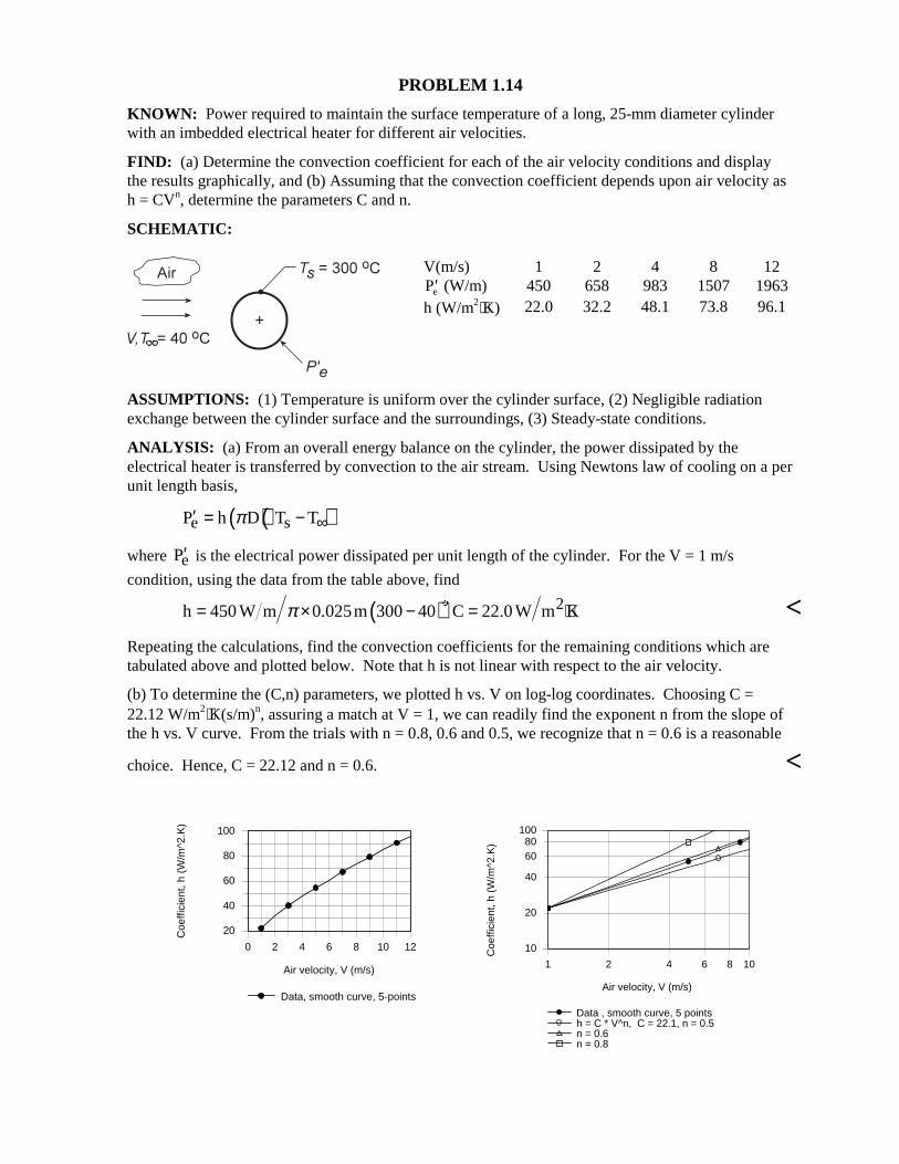
PROBLEM 1.14 KNOWN: Power required to maintain the surface temperature of a long, 25-mm diameter cylinder with an imbedded electrical heater for different air velocities. FIND: (a) Determine the convection coefficient for each of the air velocity conditions and display the results graphically, and (b) Assuming that the convection coefficient depends upon air velocity as h = CVn, determine the parameters C and n. SCHEMATIC:
V(m/s) 1 2 4 8 12 ′Pe (W/m) 450 658 983 1507 1963
h (W/m2⋅K) 22.0 32.2 48.1 73.8 96.1
ASSUMPTIONS: (1) Temperature is uniform over the cylinder surface, (2) Negligible radiation exchange between the cylinder surface and the surroundings, (3) Steady-state conditions. ANALYSIS: (a) From an overall energy balance on the cylinder, the power dissipated by the electrical heater is transferred by convection to the air stream. Using Newtons law of cooling on a per unit length basis, ( )( )e sP h D T Tπ ∞′ = − where eP′ is the electrical power dissipated per unit length of the cylinder. For the V = 1 m/s
condition, using the data from the table above, find
( ) 2h 450 W m 0.025m 300 40 C 22.0 W m Kπ= × − = ⋅$
< Repeating the calculations, find the convection coefficients for the remaining conditions which are tabulated above and plotted below. Note that h is not linear with respect to the air velocity. (b) To determine the (C,n) parameters, we plotted h vs. V on log-log coordinates. Choosing C = 22.12 W/m2⋅K(s/m)n, assuring a match at V = 1, we can readily find the exponent n from the slope of the h vs. V curve. From the trials with n = 0.8, 0.6 and 0.5, we recognize that n = 0.6 is a reasonable
choice. Hence, C = 22.12 and n = 0.6. <
0 2 4 6 8 10 12
Air velocity, V (m/s)
20
40
60
80
100
Coe
ffici
ent,
h (W
/m^2
.K)
Data, smooth curve, 5-points
1 2 4 6 8 10
Air velocity, V (m/s)
10
20
40
6080
100
Coe
ffici
ent,
h (W
/m^2
.K)
Data , smooth curve, 5 pointsh = C * V^n, C = 22.1, n = 0.5n = 0.6n = 0.8
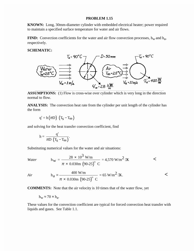
PROBLEM 1.15
KNOWN: Long, 30mm-diameter cylinder with embedded electrical heater; power requiredto maintain a specified surface temperature for water and air flows.
FIND: Convection coefficients for the water and air flow convection processes, hw and ha,respectively.
SCHEMATIC:
ASSUMPTIONS: (1) Flow is cross-wise over cylinder which is very long in the directionnormal to flow.
ANALYSIS: The convection heat rate from the cylinder per unit length of the cylinder hasthe form
( ) ( )q = h D T Tsπ′ − ∞
and solving for the heat transfer convection coefficient, find
( )q
h = .D T Tsπ
′− ∞
Substituting numerical values for the water and air situations:
Water( )
28 10 W/mh = = 4,570 W/m K
0.030m 90-25 C
32
wπ
× ⋅×
<
Air( )
400 W/mh = 65 W/m K.
0.030m 90-25 C
2a
π= ⋅
×
<
COMMENTS: Note that the air velocity is 10 times that of the water flow, yet
hw ≈ 70 × ha.
These values for the convection coefficient are typical for forced convection heat transfer withliquids and gases. See Table 1.1.
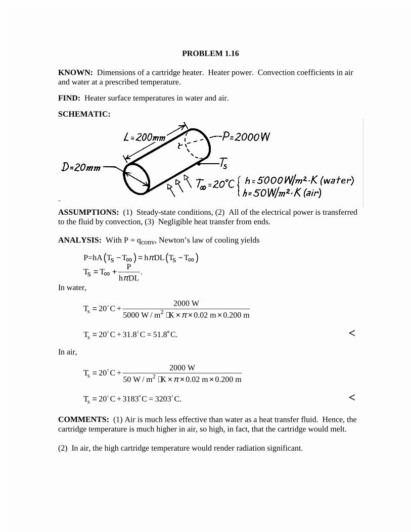
PROBLEM 1.16
KNOWN: Dimensions of a cartridge heater. Heater power. Convection coefficients in airand water at a prescribed temperature.
FIND: Heater surface temperatures in water and air.
SCHEMATIC:
ASSUMPTIONS: (1) Steady-state conditions, (2) All of the electrical power is transferredto the fluid by convection, (3) Negligible heat transfer from ends.
ANALYSIS: With P = qconv, Newton’s law of cooling yields
( ) ( )P=hA T T h DL T TP
T T .h DL
s s
s
π
π
− = −
= +∞ ∞
∞In water,
T C +2000 W
5000 W / m K 0.02 m 0.200 ms 2=⋅ × × ×
20$
π
T C + 31.8 C = 51.8 C.s = 20$ $ $ <In air,
T C +2000 W
50 W / m K 0.02 m 0.200 ms 2=⋅ × × ×
20$
π
T C + 3183 C = 3203 C.s = 20$ $ $ <
COMMENTS: (1) Air is much less effective than water as a heat transfer fluid. Hence, thecartridge temperature is much higher in air, so high, in fact, that the cartridge would melt.
(2) In air, the high cartridge temperature would render radiation significant.
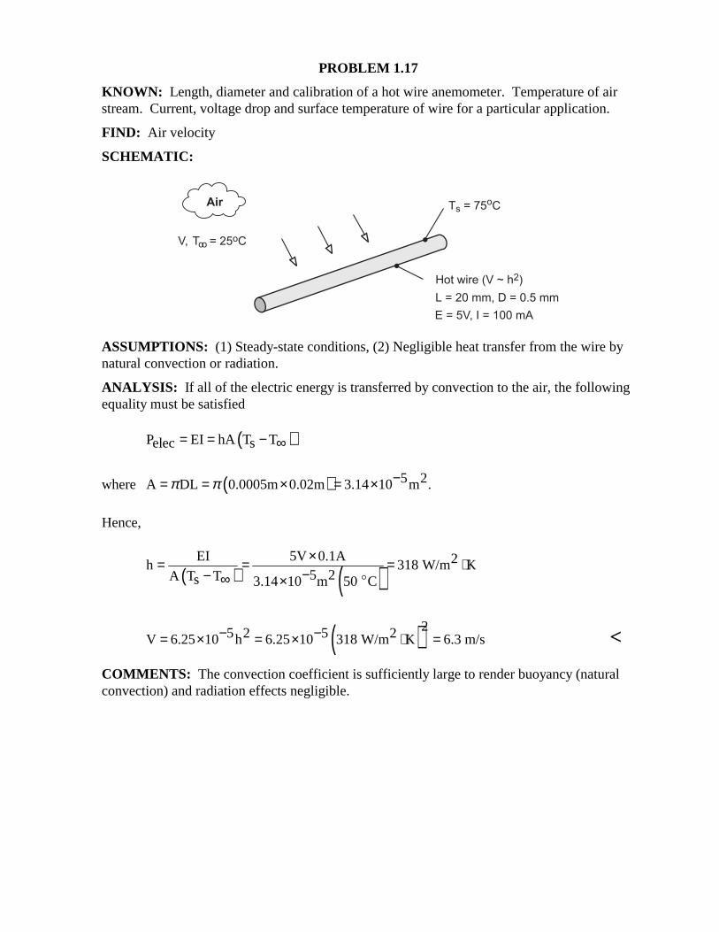
PROBLEM 1.17 KNOWN: Length, diameter and calibration of a hot wire anemometer. Temperature of air stream. Current, voltage drop and surface temperature of wire for a particular application. FIND: Air velocity SCHEMATIC:
ASSUMPTIONS: (1) Steady-state conditions, (2) Negligible heat transfer from the wire by natural convection or radiation. ANALYSIS: If all of the electric energy is transferred by convection to the air, the following equality must be satisfied ( )P EI hA T Telec s= = − ∞
where ( ) 5 2A DL 0.0005m 0.02m 3.14 10 m .π π −= = × = ×
Hence,
( ) ( )
EI 5V 0.1A 2h 318 W/m K5 2A T Ts 3.14 10 m 50 C
×= = = ⋅−− ∞ × $
( )25 2 5 2V 6.25 10 h 6.25 10 318 W/m K 6.3 m/s− −= × = × ⋅ = <
COMMENTS: The convection coefficient is sufficiently large to render buoyancy (natural convection) and radiation effects negligible.
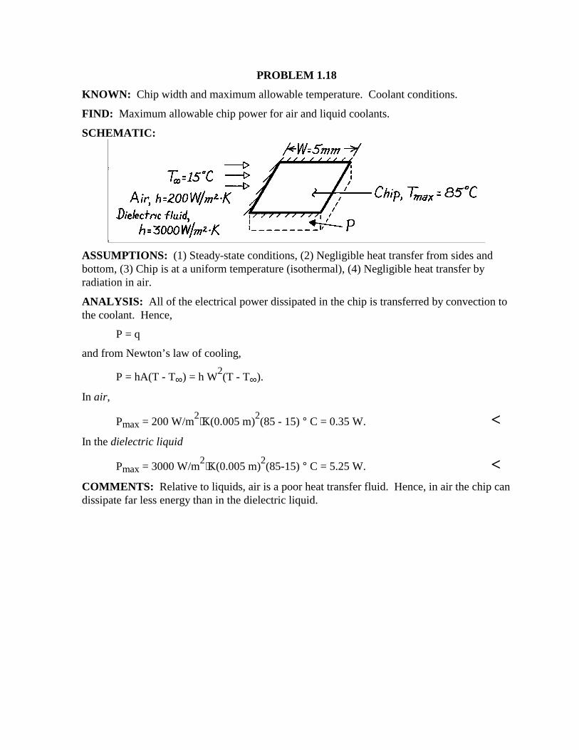
PROBLEM 1.18 KNOWN: Chip width and maximum allowable temperature. Coolant conditions. FIND: Maximum allowable chip power for air and liquid coolants. SCHEMATIC:
ASSUMPTIONS: (1) Steady-state conditions, (2) Negligible heat transfer from sides and bottom, (3) Chip is at a uniform temperature (isothermal), (4) Negligible heat transfer by radiation in air. ANALYSIS: All of the electrical power dissipated in the chip is transferred by convection to the coolant. Hence, P = q and from Newton’s law of cooling,
P = hA(T - T∞) = h W2(T - T∞).
In air,
Pmax = 200 W/m2⋅K(0.005 m)
2(85 - 15) ° C = 0.35 W. <
In the dielectric liquid
Pmax = 3000 W/m2⋅K(0.005 m)
2(85-15) ° C = 5.25 W. <
COMMENTS: Relative to liquids, air is a poor heat transfer fluid. Hence, in air the chip can dissipate far less energy than in the dielectric liquid.
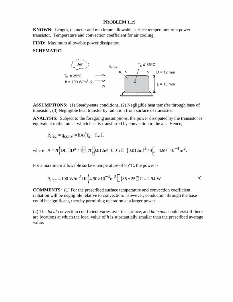
PROBLEM 1.19 KNOWN: Length, diameter and maximum allowable surface temperature of a power transistor. Temperature and convection coefficient for air cooling. FIND: Maximum allowable power dissipation. SCHEMATIC:
ASSUMPTIONS: (1) Steady-state conditions, (2) Negligible heat transfer through base of transistor, (3) Negligible heat transfer by radiation from surface of transistor. ANALYSIS: Subject to the foregoing assumptions, the power dissipated by the transistor is equivalent to the rate at which heat is transferred by convection to the air. Hence, ( )P q hA T Telec conv s= = − ∞
where ( ) ( )22 4 2A DL D / 4 0.012m 0.01m 0.012m / 4 4.90 10 m .π π − = + = × + = ×
For a maximum allowable surface temperature of 85°C, the power is
( ) ( )2 4 2P 100 W/m K 4.90 10 m 85 25 C 2.94 Welec−= ⋅ × − =$ <
COMMENTS: (1) For the prescribed surface temperature and convection coefficient, radiation will be negligible relative to convection. However, conduction through the base could be significant, thereby permitting operation at a larger power. (2) The local convection coefficient varies over the surface, and hot spots could exist if there are locations at which the local value of h is substantially smaller than the prescribed average value.
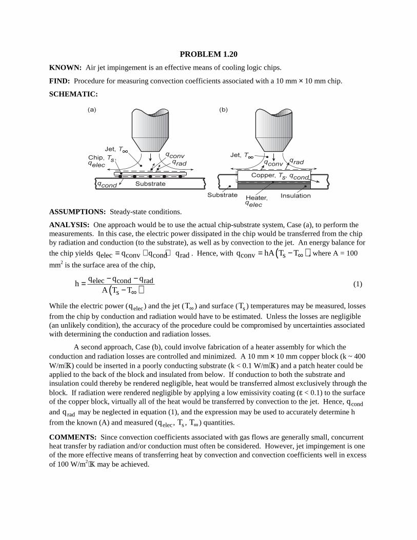
PROBLEM 1.20 KNOWN: Air jet impingement is an effective means of cooling logic chips. FIND: Procedure for measuring convection coefficients associated with a 10 mm × 10 mm chip. SCHEMATIC:
ASSUMPTIONS: Steady-state conditions. ANALYSIS: One approach would be to use the actual chip-substrate system, Case (a), to perform the measurements. In this case, the electric power dissipated in the chip would be transferred from the chip by radiation and conduction (to the substrate), as well as by convection to the jet. An energy balance for
the chip yields elec conv cond radq q q q= + + . Hence, with ( )conv sq hA T T∞= − , where A = 100
mm2 is the surface area of the chip,
( )elec cond rad
s
q q qh
A T T∞
− −=−
(1)
While the electric power (qelec) and the jet (T∞ ) and surface (Ts) temperatures may be measured, losses from the chip by conduction and radiation would have to be estimated. Unless the losses are negligible (an unlikely condition), the accuracy of the procedure could be compromised by uncertainties associated with determining the conduction and radiation losses. A second approach, Case (b), could involve fabrication of a heater assembly for which the conduction and radiation losses are controlled and minimized. A 10 mm × 10 mm copper block (k ~ 400 W/m⋅K) could be inserted in a poorly conducting substrate (k < 0.1 W/m⋅K) and a patch heater could be applied to the back of the block and insulated from below. If conduction to both the substrate and insulation could thereby be rendered negligible, heat would be transferred almost exclusively through the block. If radiation were rendered negligible by applying a low emissivity coating (ε < 0.1) to the surface of the copper block, virtually all of the heat would be transferred by convection to the jet. Hence, qcond and qrad may be neglected in equation (1), and the expression may be used to accurately determine h from the known (A) and measured (qelec, Ts, T∞ ) quantities. COMMENTS: Since convection coefficients associated with gas flows are generally small, concurrent heat transfer by radiation and/or conduction must often be considered. However, jet impingement is one of the more effective means of transferring heat by convection and convection coefficients well in excess of 100 W/m2⋅K may be achieved.
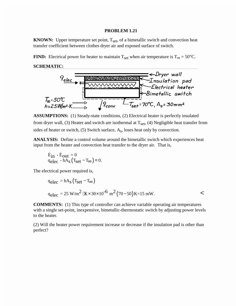
PROBLEM 1.21
KNOWN: Upper temperature set point, Tset, of a bimetallic switch and convection heattransfer coefficient between clothes dryer air and exposed surface of switch.
FIND: Electrical power for heater to maintain Tset when air temperature is T∞ = 50°C.
SCHEMATIC:
ASSUMPTIONS: (1) Steady-state conditions, (2) Electrical heater is perfectly insulated
from dryer wall, (3) Heater and switch are isothermal at Tset, (4) Negligible heat transfer from
sides of heater or switch, (5) Switch surface, As, loses heat only by convection.
ANALYSIS: Define a control volume around the bimetallic switch which experiences heatinput from the heater and convection heat transfer to the dryer air. That is,
( )E - E = 0q - hA T T 0.
outins setelec − =∞
The electrical power required is,
( )q = hA T Ts setelec − ∞
( )q = 25 W/m K 30 10 m 70 50 K=15 mW.2 -6 2elec ⋅ × × − <
COMMENTS: (1) This type of controller can achieve variable operating air temperatureswith a single set-point, inexpensive, bimetallic-thermostatic switch by adjusting power levelsto the heater.
(2) Will the heater power requirement increase or decrease if the insulation pad is other thanperfect?
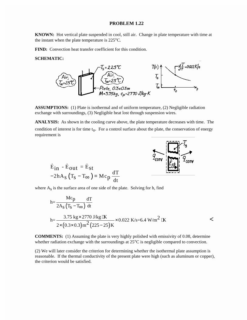
PROBLEM 1.22
KNOWN: Hot vertical plate suspended in cool, still air. Change in plate temperature with time atthe instant when the plate temperature is 225°C.
FIND: Convection heat transfer coefficient for this condition.
SCHEMATIC:
ASSUMPTIONS: (1) Plate is isothermal and of uniform temperature, (2) Negligible radiationexchange with surroundings, (3) Negligible heat lost through suspension wires.
ANALYSIS: As shown in the cooling curve above, the plate temperature decreases with time. The
condition of interest is for time to. For a control surface about the plate, the conservation of energyrequirement is
( )E - E = E
dT2hA T T Mc
dt
out stin
s s p− − =∞
where As is the surface area of one side of the plate. Solving for h, find
( )Mc dT
h=2A T T dt
p
s s − ∞
( ) ( )3.75 kg 2770 J/kg K
h= 0.022 K/s=6.4 W/m K2 0.3 0.3 m 225 25 K
22
× ⋅ × ⋅× × −
<
COMMENTS: (1) Assuming the plate is very highly polished with emissivity of 0.08, determinewhether radiation exchange with the surroundings at 25°C is negligible compared to convection.
(2) We will later consider the criterion for determining whether the isothermal plate assumption isreasonable. If the thermal conductivity of the present plate were high (such as aluminum or copper),the criterion would be satisfied.
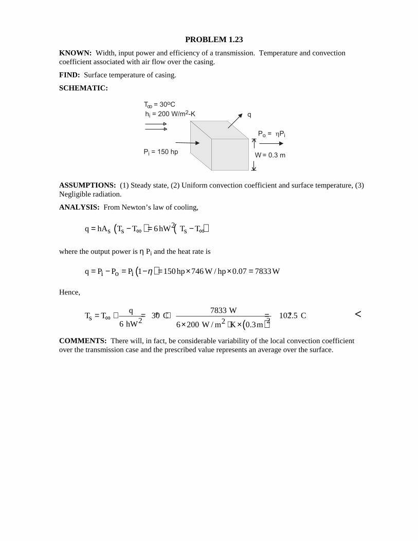
PROBLEM 1.23 KNOWN: Width, input power and efficiency of a transmission. Temperature and convection coefficient associated with air flow over the casing. FIND: Surface temperature of casing. SCHEMATIC:
ASSUMPTIONS: (1) Steady state, (2) Uniform convection coefficient and surface temperature, (3) Negligible radiation. ANALYSIS: From Newton’s law of cooling,
( ) ( )2s s sq hA T T 6hW T T∞ ∞= − = −
where the output power is η Pi and the heat rate is
( )i o iq P P P 1 150hp 746 W / hp 0.07 7833Wη= − = − = × × =
Hence,
( )
s 2 22
q 7833 WT T 30 C 102.5 C
6 hW 6 200 W / m K 0.3m∞= + = ° + = °
× ⋅ × <
COMMENTS: There will, in fact, be considerable variability of the local convection coefficient over the transmission case and the prescribed value represents an average over the surface.
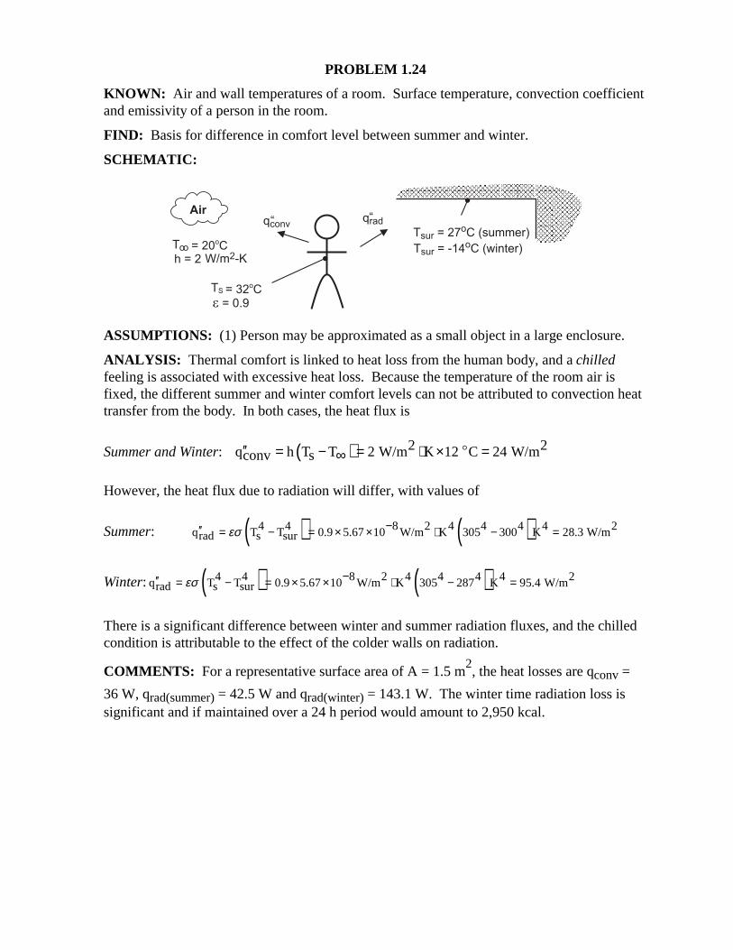
PROBLEM 1.24 KNOWN: Air and wall temperatures of a room. Surface temperature, convection coefficient and emissivity of a person in the room. FIND: Basis for difference in comfort level between summer and winter. SCHEMATIC:
ASSUMPTIONS: (1) Person may be approximated as a small object in a large enclosure. ANALYSIS: Thermal comfort is linked to heat loss from the human body, and a chilled feeling is associated with excessive heat loss. Because the temperature of the room air is fixed, the different summer and winter comfort levels can not be attributed to convection heat transfer from the body. In both cases, the heat flux is
Summer and Winter: ( ) 2 2q h T T 2 W/m K 12 C 24 W/mconv s′′ = − = ⋅ × =∞$
However, the heat flux due to radiation will differ, with values of
Summer: ( ) ( )4 4 8 2 4 4 4 4 2q T T 0.9 5.67 10 W/m K 305 300 K 28.3 W/mrad s surεσ −′′ = − = × × ⋅ − =
Winter: ( ) ( )4 4 8 2 4 4 4 4 2q T T 0.9 5.67 10 W/m K 305 287 K 95.4 W/mrad s surεσ −′′ = − = × × ⋅ − =
There is a significant difference between winter and summer radiation fluxes, and the chilled condition is attributable to the effect of the colder walls on radiation. COMMENTS: For a representative surface area of A = 1.5 m
2, the heat losses are qconv =
36 W, qrad(summer) = 42.5 W and qrad(winter) = 143.1 W. The winter time radiation loss is significant and if maintained over a 24 h period would amount to 2,950 kcal.
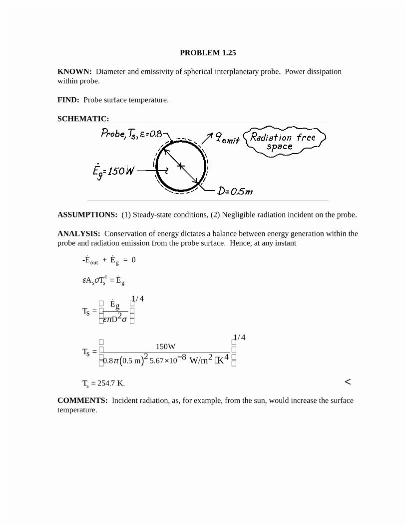
PROBLEM 1.25
KNOWN: Diameter and emissivity of spherical interplanetary probe. Power dissipationwithin probe.
FIND: Probe surface temperature.
SCHEMATIC:
ASSUMPTIONS: (1) Steady-state conditions, (2) Negligible radiation incident on the probe.
ANALYSIS: Conservation of energy dictates a balance between energy generation within theprobe and radiation emission from the probe surface. Hence, at any instant
-E + E = 0out g
ε σA T Es s4
g=
ET
D
1/ 4g
s 2επ σ
=
( )150W
T0.8 0.5 m 5.67 10
1/ 4
s 2 8 2 4 W/m Kπ
= ×
− ⋅
T K.s = 254 7. <
COMMENTS: Incident radiation, as, for example, from the sun, would increase the surfacetemperature.
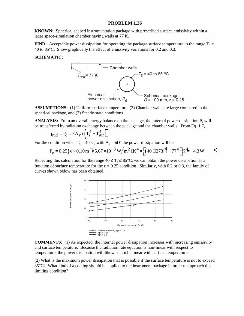
PROBLEM 1.26 KNOWN: Spherical shaped instrumentation package with prescribed surface emissivity within a large space-simulation chamber having walls at 77 K. FIND: Acceptable power dissipation for operating the package surface temperature in the range Ts = 40 to 85°C. Show graphically the effect of emissivity variations for 0.2 and 0.3. SCHEMATIC:
ASSUMPTIONS: (1) Uniform surface temperature, (2) Chamber walls are large compared to the spherical package, and (3) Steady-state conditions. ANALYSIS: From an overall energy balance on the package, the internal power dissipation Pe will be transferred by radiation exchange between the package and the chamber walls. From Eq. 1.7,
( )4 4rad e s s surq P A T Tε σ= = −
For the condition when Ts = 40°C, with As = πD2 the power dissipation will be
( ) ( )48 2 4 4 4eP 0.25 0.10m 5.67 10 W m K 40 273 77 K 4.3Wπ − = × × × ⋅ × + − =
<
Repeating this calculation for the range 40 ≤ Ts ≤ 85°C, we can obtain the power dissipation as a function of surface temperature for the ε = 0.25 condition. Similarly, with 0.2 or 0.3, the family of curves shown below has been obtained.
40 50 60 70 80 90
Surface temperature, Ts (C)
2
4
6
8
10
Pow
er d
issi
patio
n, P
e (W
)
Surface emissivity, eps = 0.3eps = 0.25eps = 0.2
COMMENTS: (1) As expected, the internal power dissipation increases with increasing emissivity and surface temperature. Because the radiation rate equation is non-linear with respect to temperature, the power dissipation will likewise not be linear with surface temperature. (2) What is the maximum power dissipation that is possible if the surface temperature is not to exceed 85°C? What kind of a coating should be applied to the instrument package in order to approach this limiting condition?
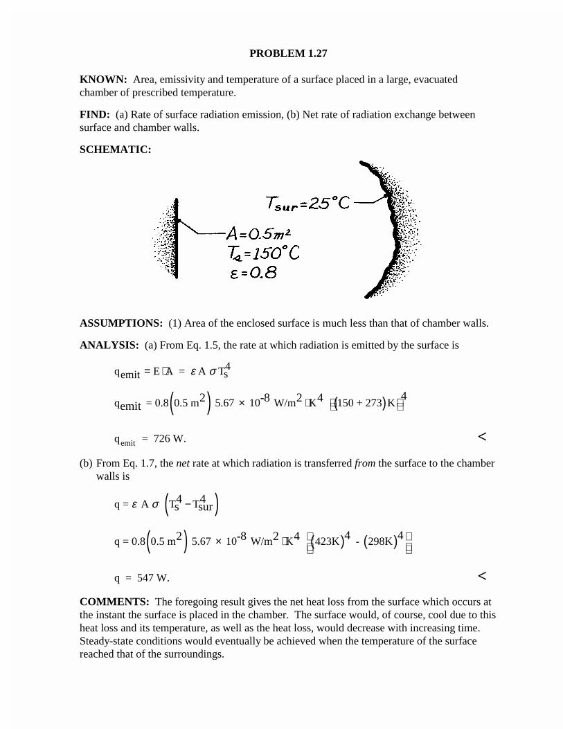
PROBLEM 1.27
KNOWN: Area, emissivity and temperature of a surface placed in a large, evacuatedchamber of prescribed temperature.
FIND: (a) Rate of surface radiation emission, (b) Net rate of radiation exchange betweensurface and chamber walls.
SCHEMATIC:
ASSUMPTIONS: (1) Area of the enclosed surface is much less than that of chamber walls.
ANALYSIS: (a) From Eq. 1.5, the rate at which radiation is emitted by the surface is
qemit E A = A Ts4= ⋅ ε σ
( ) ( )q = 0.8 0.5 m 5.67 10 W/m K 150 + 273 K42 -8 2 4
emit × ⋅
q = 726 W.emit <
(b) From Eq. 1.7, the net rate at which radiation is transferred from the surface to the chamberwalls is
( )q = A T T4 4s surε σ −
( ) ( ) ( )q = 0.8 0.5 m 5.67 10 W/m K 423K - 298K4 42 -8 2 4 × ⋅
q = 547 W. <
COMMENTS: The foregoing result gives the net heat loss from the surface which occurs atthe instant the surface is placed in the chamber. The surface would, of course, cool due to thisheat loss and its temperature, as well as the heat loss, would decrease with increasing time.Steady-state conditions would eventually be achieved when the temperature of the surfacereached that of the surroundings.
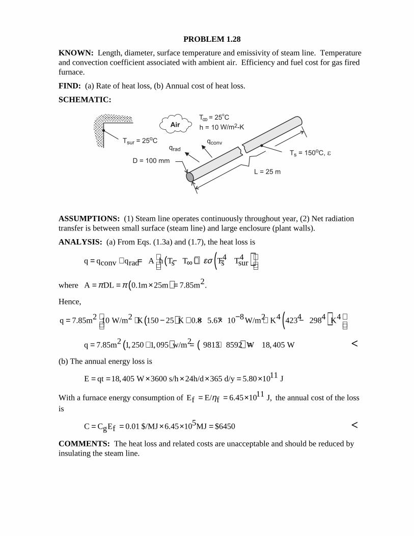
PROBLEM 1.28 KNOWN: Length, diameter, surface temperature and emissivity of steam line. Temperature and convection coefficient associated with ambient air. Efficiency and fuel cost for gas fired furnace. FIND: (a) Rate of heat loss, (b) Annual cost of heat loss. SCHEMATIC:
ASSUMPTIONS: (1) Steam line operates continuously throughout year, (2) Net radiation transfer is between small surface (steam line) and large enclosure (plant walls). ANALYSIS: (a) From Eqs. (1.3a) and (1.7), the heat loss is
( ) ( )4 4q q q A h T T T Tconv rad s s surεσ = + = − + −∞
where ( ) 2A DL 0.1m 25m 7.85m .π π= = × = Hence,
( ) ( )2 2 8 2 4 4 4 4q 7.85m 10 W/m K 150 25 K 0.8 5.67 10 W/m K 423 298 K− = ⋅ − + × × ⋅ −
( ) ( )2 2q 7.85m 1,250 1,095 w/m 9813 8592 W 18,405 W= + = + = < (b) The annual energy loss is
11E qt 18,405 W 3600 s/h 24h/d 365 d/y 5.80 10 J= = × × × = ×
With a furnace energy consumption of 11E E/ 6.45 10 J,f fη= = × the annual cost of the loss is
5C C E 0.01 $/MJ 6.45 10 MJ $6450g f= = × × = < COMMENTS: The heat loss and related costs are unacceptable and should be reduced by insulating the steam line.
PROBLEM 1.29 KNOWN: Exact and approximate expressions for the linearized radiation coefficient, hr and hra, respectively. FIND: (a) Comparison of the coefficients with ε = 0.05 and 0.9 and surface temperatures which may exceed that of the surroundings (Tsur = 25°C) by 10 to 100°C; also comparison with a free convection coefficient correlation, (b) Plot of the relative error (hr - rra)/hr as a function of the furnace temperature associated with a workpiece at Ts = 25°C having ε = 0.05, 0.2 or 0.9. ASSUMPTIONS: (1) Furnace walls are large compared to the workpiece and (2) Steady-state conditions. ANALYSIS: (a) The linearized radiation coefficient, Eq. 1.9, follows from the radiation exchange rate equation,
( )( )2 2r s sur s surh T T T Tεσ= + +
If Ts ≈ Tsur, the coefficient may be approximated by the simpler expression
( )3r,a s surh 4 T T T T 2εσ= = +
For the condition of ε = 0.05, Ts = Tsur + 10 = 35°C = 308 K and Tsur = 25°C = 298 K, find that
( )( )8 2 4 2 2 3 2rh 0.05 5.67 10 W m K 308 298 308 298 K 0.32 W m K−= × × ⋅ + + = ⋅ <
( )( )38 2 4 3 2r,ah 4 0.05 5.67 10 W m K 308 298 2 K 0.32 W m K−= × × × ⋅ + = ⋅ <
The free convection coefficient with Ts = 35°C and T∞ = Tsur = 25°C, find that
( ) ( )1/3 1/31/3 2sh 0.98 T 0.98 T T 0.98 308 298 2.1W m K∞= ∆ = − = − = ⋅ <
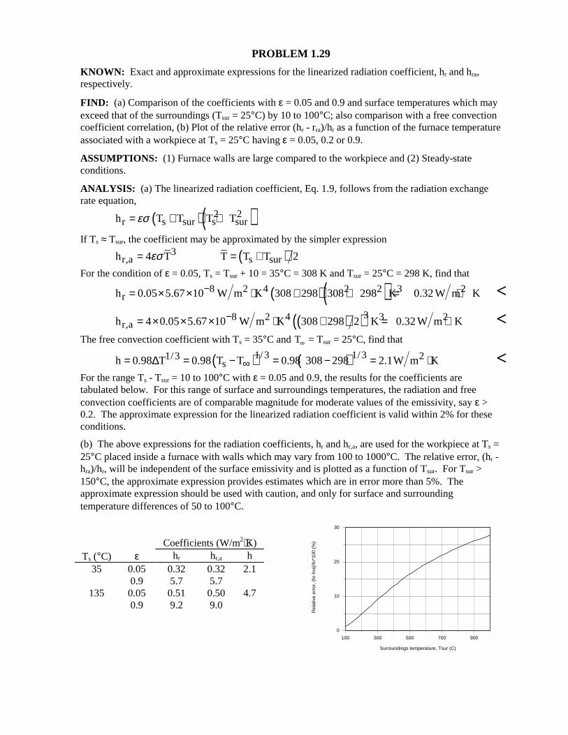
For the range Ts - Tsur = 10 to 100°C with ε = 0.05 and 0.9, the results for the coefficients are tabulated below. For this range of surface and surroundings temperatures, the radiation and free convection coefficients are of comparable magnitude for moderate values of the emissivity, say ε > 0.2. The approximate expression for the linearized radiation coefficient is valid within 2% for these conditions. (b) The above expressions for the radiation coefficients, hr and hr,a, are used for the workpiece at Ts = 25°C placed inside a furnace with walls which may vary from 100 to 1000°C. The relative error, (hr - hra)/hr, will be independent of the surface emissivity and is plotted as a function of Tsur. For Tsur > 150°C, the approximate expression provides estimates which are in error more than 5%. The approximate expression should be used with caution, and only for surface and surrounding temperature differences of 50 to 100°C.
Coefficients (W/m2⋅K)
Ts (°C) ε hr hr,a h 35 0.05 0.32 0.32 2.1 0.9 5.7 5.7
135 0.05 0.51 0.50 4.7 0.9 9.2 9.0
100 300 500 700 900
Surroundings temperature, Tsur (C)
0
10
20
30
Rel
ativ
e er
ror,
(hr
-hra
)/hr
*100
(%
)
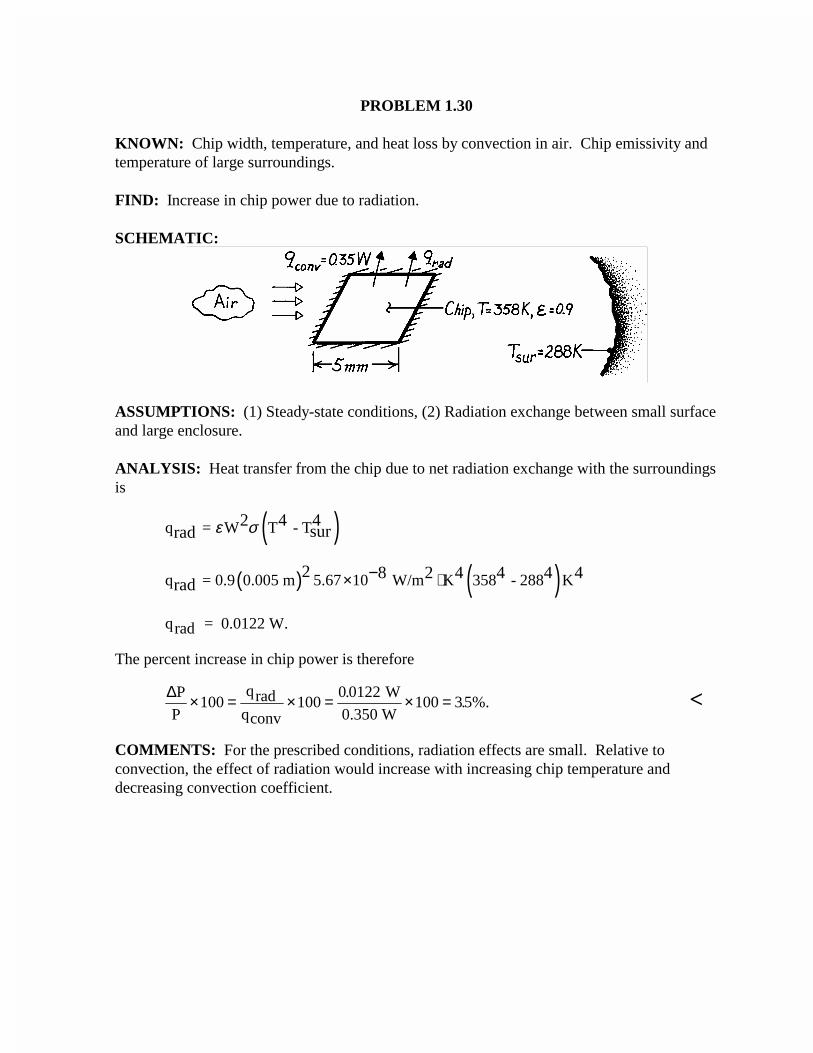
PROBLEM 1.30
KNOWN: Chip width, temperature, and heat loss by convection in air. Chip emissivity andtemperature of large surroundings.
FIND: Increase in chip power due to radiation.
SCHEMATIC:
ASSUMPTIONS: (1) Steady-state conditions, (2) Radiation exchange between small surfaceand large enclosure.
ANALYSIS: Heat transfer from the chip due to net radiation exchange with the surroundingsis
( )q = W T - T2 4 4surrad ε σ
( ) ( )q = 0.9 0.005 m 5.67 10 W/m K 358 - 288 K2 8 2 4 4 4 4rad × ⋅−
qrad = 0.0122 W.
The percent increase in chip power is therefore
∆P
P
qradqconv
W
0.350 W× = × = × =100 100
0 0122100 35%.
.. <
COMMENTS: For the prescribed conditions, radiation effects are small. Relative toconvection, the effect of radiation would increase with increasing chip temperature anddecreasing convection coefficient.
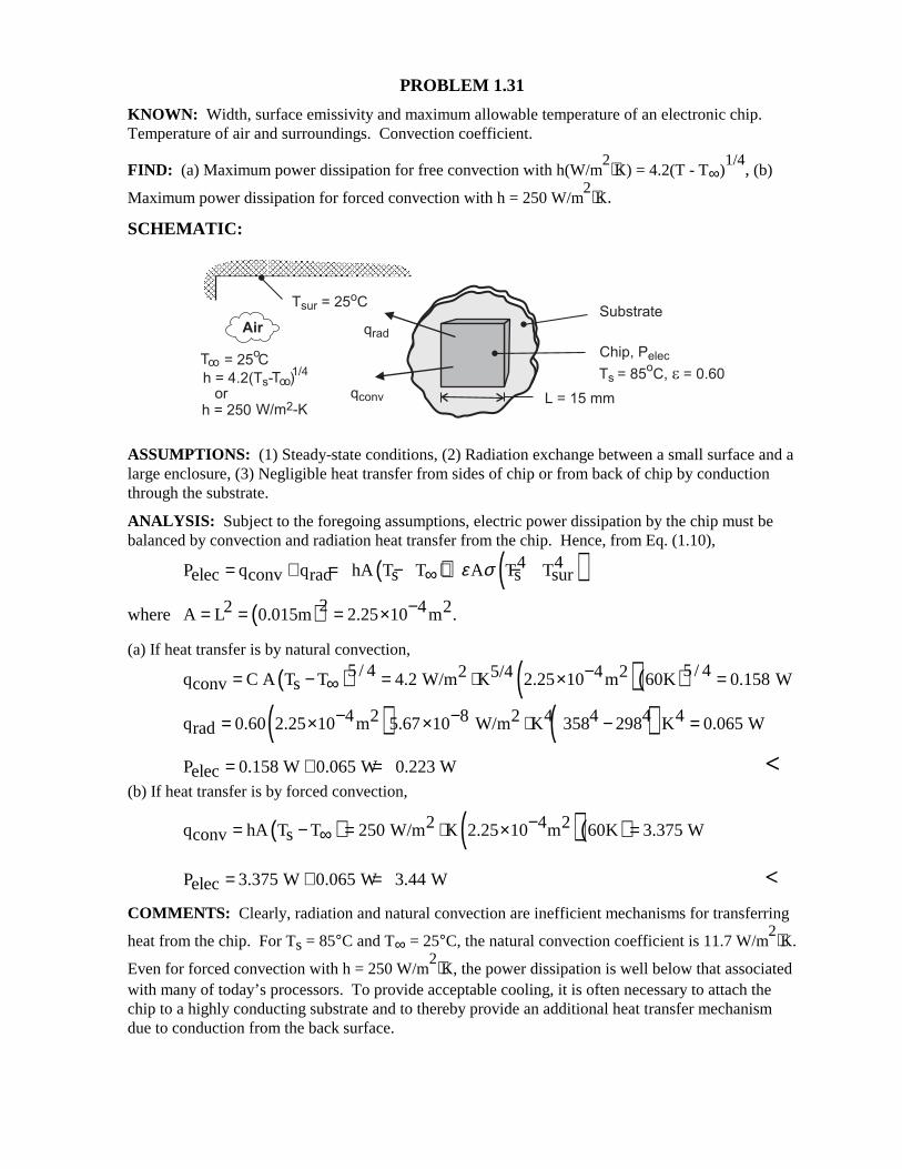
PROBLEM 1.31 KNOWN: Width, surface emissivity and maximum allowable temperature of an electronic chip. Temperature of air and surroundings. Convection coefficient.
FIND: (a) Maximum power dissipation for free convection with h(W/m2⋅K) = 4.2(T - T∞)
1/4, (b)
Maximum power dissipation for forced convection with h = 250 W/m2⋅K.
SCHEMATIC:
ASSUMPTIONS: (1) Steady-state conditions, (2) Radiation exchange between a small surface and a large enclosure, (3) Negligible heat transfer from sides of chip or from back of chip by conduction through the substrate. ANALYSIS: Subject to the foregoing assumptions, electric power dissipation by the chip must be balanced by convection and radiation heat transfer from the chip. Hence, from Eq. (1.10),
( ) ( )4 4P q q hA T T A T Telec conv rad s s surε σ= + = − + −∞
where ( )22 4 2A L 0.015m 2.25 10 m .−= = = × (a) If heat transfer is by natural convection,
( ) ( )( )5 / 4 5 / 42 5/4 4 2q C A T T 4.2 W/m K 2.25 10 m 60K 0.158 Wconv s−= − = ⋅ × =∞
( ) ( )4 2 8 2 4 4 4 4q 0.60 2.25 10 m 5.67 10 W/m K 358 298 K 0.065 Wrad− −= × × ⋅ − =
P 0.158 W 0.065 W 0.223 Welec= + = < (b) If heat transfer is by forced convection,
( ) ( )( )2 4 2q hA T T 250 W/m K 2.25 10 m 60K 3.375 Wconv s−= − = ⋅ × =∞
P 3.375 W 0.065 W 3.44 Welec= + = < COMMENTS: Clearly, radiation and natural convection are inefficient mechanisms for transferring
heat from the chip. For Ts = 85°C and T∞ = 25°C, the natural convection coefficient is 11.7 W/m2⋅K.
Even for forced convection with h = 250 W/m2⋅K, the power dissipation is well below that associated
with many of today’s processors. To provide acceptable cooling, it is often necessary to attach the chip to a highly conducting substrate and to thereby provide an additional heat transfer mechanism due to conduction from the back surface.
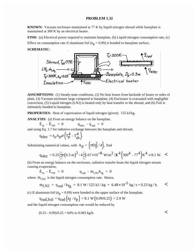
PROBLEM 1.32
KNOWN: Vacuum enclosure maintained at 77 K by liquid nitrogen shroud while baseplate ismaintained at 300 K by an electrical heater.
FIND: (a) Electrical power required to maintain baseplate, (b) Liquid nitrogen consumption rate, (c)
Effect on consumption rate if aluminum foil (εp = 0.09) is bonded to baseplate surface.
SCHEMATIC:
ASSUMPTIONS: (1) Steady-state conditions, (2) No heat losses from backside of heater or sides ofplate, (3) Vacuum enclosure large compared to baseplate, (4) Enclosure is evacuated with negligibleconvection, (5) Liquid nitrogen (LN2) is heated only by heat transfer to the shroud, and (6) Foil isintimately bonded to baseplate.
PROPERTIES: Heat of vaporization of liquid nitrogen (given): 125 kJ/kg.
ANALYSIS: (a) From an energy balance on the baseplate, E - E = 0 q - q = 0in out elec rad
and using Eq. 1.7 for radiative exchange between the baseplate and shroud,
( )pq = A T - T .4 4p pelec shε σ
Substituting numerical values, with ( )A = D / 4 ,2p pπ find
( ) ( )q = 0.25 0.3 m / 4 5.67 10 W/m K 300 - 77 K 8.1 W.2 8 2 4 4 4 4elec π × ⋅ =
− <(b) From an energy balance on the enclosure, radiative transfer heats the liquid nitrogen streamcausing evaporation,
E - E = 0 q - m h = 0in out rad LN2 fg
where mLN2 is the liquid nitrogen consumption rate. Hence,
/mLN2 = qrad hfg = 8.1 W / 125 kJ / kg = 6.48 10-5 kg / s = 0.23 kg / h.× <(c) If aluminum foil (εp = 0.09) were bonded to the upper surface of the baseplate,
( ) ( )q = q / = 8.1 W 0.09/0.25 = 2.9 Wprad,foil rad fε εand the liquid nitrogen consumption rate would be reduced by
(0.25 - 0.09)/0.25 = 64% to 0.083 kg/h. <
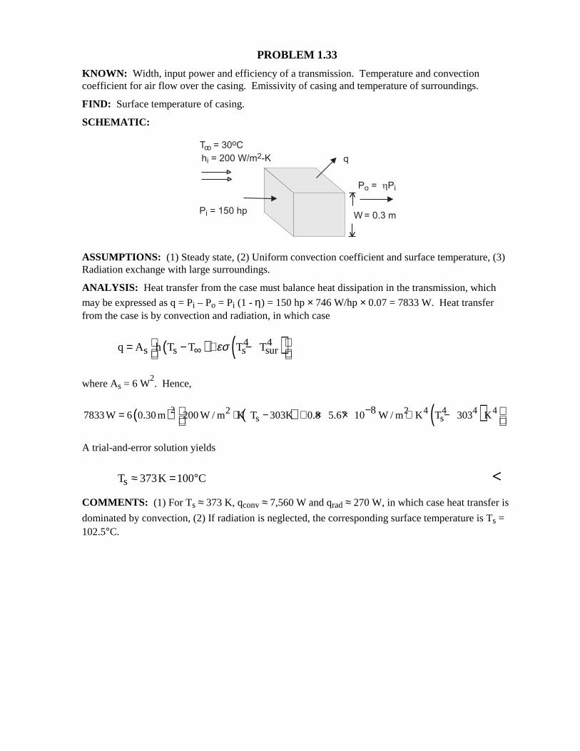
PROBLEM 1.33 KNOWN: Width, input power and efficiency of a transmission. Temperature and convection coefficient for air flow over the casing. Emissivity of casing and temperature of surroundings. FIND: Surface temperature of casing. SCHEMATIC:
ASSUMPTIONS: (1) Steady state, (2) Uniform convection coefficient and surface temperature, (3) Radiation exchange with large surroundings. ANALYSIS: Heat transfer from the case must balance heat dissipation in the transmission, which
may be expressed as q = Pi – Po = Pi (1 - η) = 150 hp × 746 W/hp × 0.07 = 7833 W. Heat transfer from the case is by convection and radiation, in which case
( ) ( )4 4s s s surq A h T T T Tεσ∞
= − + −
where As = 6 W2. Hence,
( ) ( ) ( )2 2 2 4 4 4 4s s
87833W 6 0.30 m 200 W / m K T 303K 0.8 5.67 10 W / m K T 303 K−= ⋅ − + × × ⋅ −
A trial-and-error solution yields
sT 373K 100 C≈ = ° < COMMENTS: (1) For Ts ≈ 373 K, qconv ≈ 7,560 W and qrad ≈ 270 W, in which case heat transfer is
dominated by convection, (2) If radiation is neglected, the corresponding surface temperature is Ts = 102.5°C.
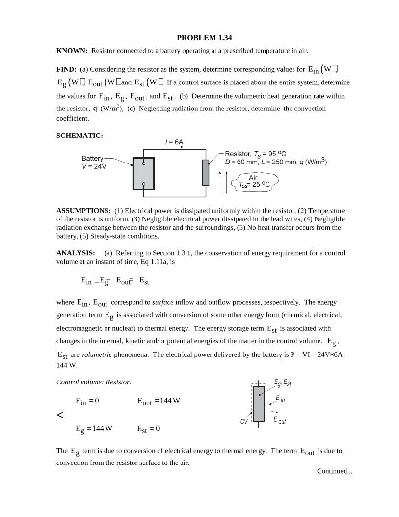
PROBLEM 1.34 KNOWN: Resistor connected to a battery operating at a prescribed temperature in air.
FIND: (a) Considering the resistor as the system, determine corresponding values for ( )inE W ,
( )gE W , ( )outE W and ( )stE W . If a control surface is placed about the entire system, determine
the values for inE , gE , outE , and stE . (b) Determine the volumetric heat generation rate within
the resistor, q (W/m3), (c) Neglecting radiation from the resistor, determine the convection coefficient. SCHEMATIC:
ASSUMPTIONS: (1) Electrical power is dissipated uniformly within the resistor, (2) Temperature of the resistor is uniform, (3) Negligible electrical power dissipated in the lead wires, (4) Negligible radiation exchange between the resistor and the surroundings, (5) No heat transfer occurs from the battery, (5) Steady-state conditions. ANALYSIS: (a) Referring to Section 1.3.1, the conservation of energy requirement for a control volume at an instant of time, Eq 1.11a, is
in g out stE E E E+ − =
where in outE , E correspond to surface inflow and outflow processes, respectively. The energy
generation term gE is associated with conversion of some other energy form (chemical, electrical,
electromagnetic or nuclear) to thermal energy. The energy storage term stE is associated with
changes in the internal, kinetic and/or potential energies of the matter in the control volume. gE ,
stE are volumetric phenomena. The electrical power delivered by the battery is P = VI = 24V×6A =
144 W. Control volume: Resistor.
in outE 0 E 144 W= =
<
g stE 144 W E 0= =
The gE term is due to conversion of electrical energy to thermal energy. The term outE is due to
convection from the resistor surface to the air. Continued...
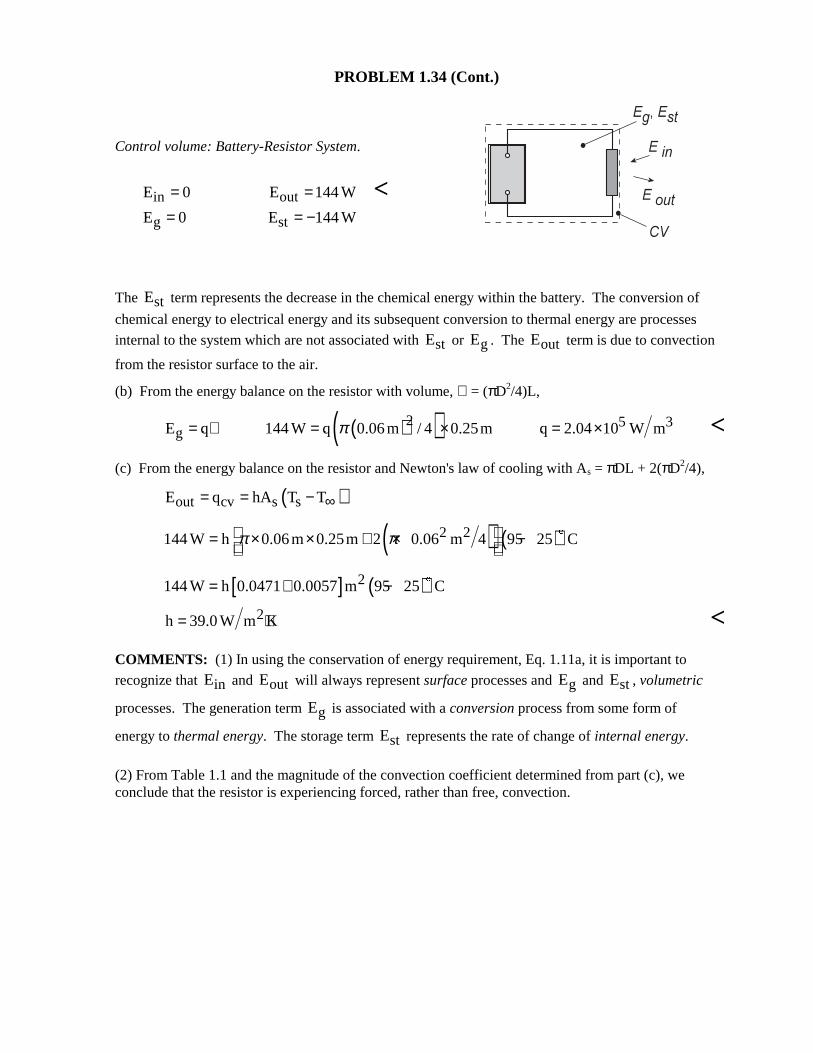
PROBLEM 1.34 (Cont.)
Control volume: Battery-Resistor System.
in outE 0 E 144 W= = <
g stE 0 E 144 W= = −
The stE term represents the decrease in the chemical energy within the battery. The conversion of
chemical energy to electrical energy and its subsequent conversion to thermal energy are processes
internal to the system which are not associated with stE or gE . The outE term is due to convection
from the resistor surface to the air. (b) From the energy balance on the resistor with volume, ∀ = (πD2/4)L,
( )( )2 5 3gE q 144 W q 0.06m / 4 0.25m q 2.04 10 W mπ= ∀ = × = × <
(c) From the energy balance on the resistor and Newton's law of cooling with As = πDL + 2(πD2/4), ( )out cv s sE q hA T T∞= = −
( ) ( )2 2144 W h 0.06m 0.25m 2 0.06 m 4 95 25 Cπ π = × × + × − $
[ ] ( )2144 W h 0.0471 0.0057 m 95 25 C= + − $
2h 39.0 W m K= ⋅ < COMMENTS: (1) In using the conservation of energy requirement, Eq. 1.11a, it is important to
recognize that inE and outE will always represent surface processes and gE and stE , volumetric
processes. The generation term gE is associated with a conversion process from some form of
energy to thermal energy. The storage term stE represents the rate of change of internal energy.
(2) From Table 1.1 and the magnitude of the convection coefficient determined from part (c), we conclude that the resistor is experiencing forced, rather than free, convection.
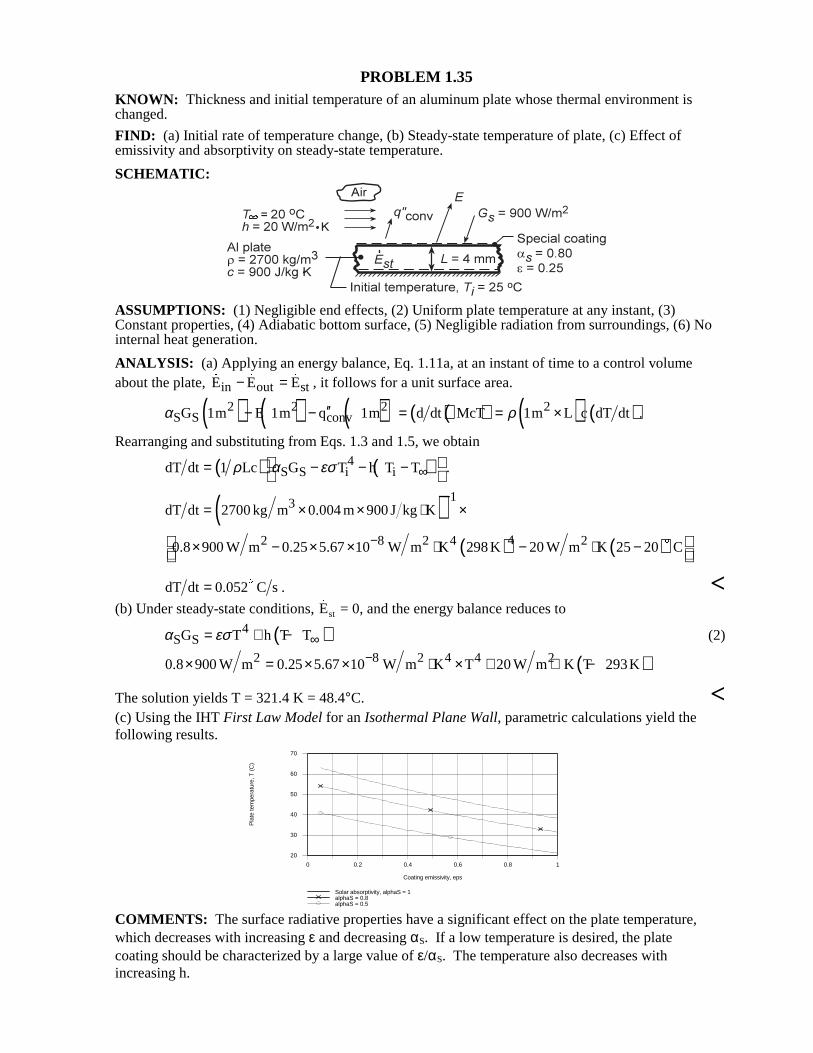
PROBLEM 1.35 KNOWN: Thickness and initial temperature of an aluminum plate whose thermal environment is changed. FIND: (a) Initial rate of temperature change, (b) Steady-state temperature of plate, (c) Effect of emissivity and absorptivity on steady-state temperature. SCHEMATIC:
ASSUMPTIONS: (1) Negligible end effects, (2) Uniform plate temperature at any instant, (3) Constant properties, (4) Adiabatic bottom surface, (5) Negligible radiation from surroundings, (6) No internal heat generation. ANALYSIS: (a) Applying an energy balance, Eq. 1.11a, at an instant of time to a control volume about the plate, in out stE E E− = , it follows for a unit surface area.
( ) ( ) ( ) ( )( ) ( ) ( )2 2 2 2S S convG 1m E 1m q 1m d dt McT 1m L c dT dtα ρ′′− − = = × .
Rearranging and substituting from Eqs. 1.3 and 1.5, we obtain
( ) ( )4S S i idT dt 1 Lc G T h T Tρ α εσ ∞= − − −
.
( ) 13dT dt 2700 kg m 0.004 m 900 J kg K−
= × × ⋅ ×
( ) ( )42 8 2 4 20.8 900 W m 0.25 5.67 10 W m K 298K 20 W m K 25 20 C−× − × × ⋅ − ⋅ −
$
dT dt 0.052 C s= $ . <
(b) Under steady-state conditions, Est = 0, and the energy balance reduces to
( )4S SG T h T Tα εσ ∞= + − (2)
( )2 8 2 4 4 20.8 900 W m 0.25 5.67 10 W m K T 20 W m K T 293K−× = × × ⋅ × + ⋅ −
The solution yields T = 321.4 K = 48.4°C. < (c) Using the IHT First Law Model for an Isothermal Plane Wall, parametric calculations yield the following results.
0 0.2 0.4 0.6 0.8 1
Coating emissivity, eps
20
30
40
50
60
70
Pla
te te
mpe
ratu
re, T
(C
)
Solar absorptivity, alphaS = 1alphaS = 0.8alphaS = 0.5
COMMENTS: The surface radiative properties have a significant effect on the plate temperature, which decreases with increasing ε and decreasing αS. If a low temperature is desired, the plate coating should be characterized by a large value of ε/αS. The temperature also decreases with increasing h.
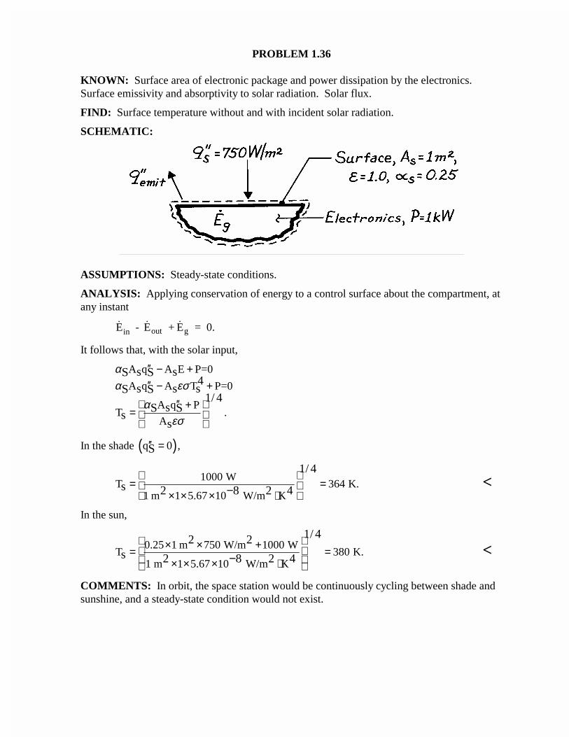
PROBLEM 1.36
KNOWN: Surface area of electronic package and power dissipation by the electronics.Surface emissivity and absorptivity to solar radiation. Solar flux.
FIND: Surface temperature without and with incident solar radiation.
SCHEMATIC:
ASSUMPTIONS: Steady-state conditions.
ANALYSIS: Applying conservation of energy to a control surface about the compartment, atany instant
E - E + E = 0.in out g
It follows that, with the solar input,
A q A E P=0
A q A T P=0
A q PT .
A
s sS S4
s s sS S1/ 4
sS Ss
s
αα εσ
αεσ
′′ − +′′ − +
′′ +=
In the shade ( )q 0 ,S′′ =
1000 WT 364 K.
1 m 1 5.67 10 W/m K
1/ 4
s 2 8 2 4
= = × × × ⋅ − <
In the sun,
0.25 1 m 750 W/m 1000 WT 380 K.
1 m 1 5.67 10 W/m K
1/ 42 2s 2 8 2 4
× × + = = × × × ⋅
− <
COMMENTS: In orbit, the space station would be continuously cycling between shade andsunshine, and a steady-state condition would not exist.
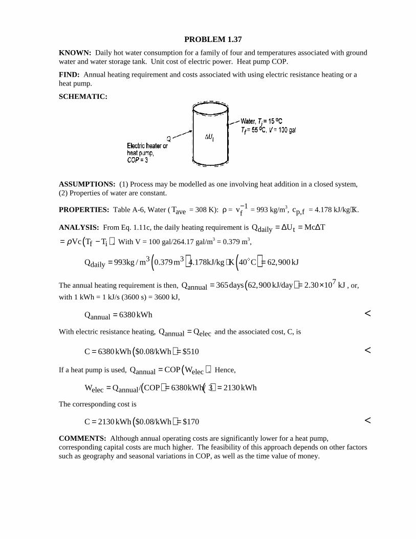
PROBLEM 1.37 KNOWN: Daily hot water consumption for a family of four and temperatures associated with ground water and water storage tank. Unit cost of electric power. Heat pump COP. FIND: Annual heating requirement and costs associated with using electric resistance heating or a heat pump. SCHEMATIC:
ASSUMPTIONS: (1) Process may be modelled as one involving heat addition in a closed system, (2) Properties of water are constant.
PROPERTIES: Table A-6, Water (aveT = 308 K): ρ = 1fv− = 993 kg/m3, p,fc = 4.178 kJ/kg⋅K.
ANALYSIS: From Eq. 1.11c, the daily heating requirement is daily tQ U Mc T= ∆ = ∆
( )f iVc T Tρ= − . With V = 100 gal/264.17 gal/m3 = 0.379 m3,
( ) ( )3 3dailyQ 993kg / m 0.379m 4.178kJ/kg K 40 C 62,900kJ= ⋅ =$
The annual heating requirement is then, ( ) 7annualQ 365days 62,900kJ/day 2.30 10 kJ= = × , or,
with 1 kWh = 1 kJ/s (3600 s) = 3600 kJ,
annualQ 6380kWh= < With electric resistance heating, annual elecQ Q= and the associated cost, C, is
( )C 6380kWh $0.08/kWh $510= = < If a heat pump is used, ( )annual elecQ COP W .= Hence, ( ) ( )elec annualW Q / COP 6380kWh/ 3 2130kWh= = = The corresponding cost is
( )C 2130kWh $0.08/kWh $170= = < COMMENTS: Although annual operating costs are significantly lower for a heat pump, corresponding capital costs are much higher. The feasibility of this approach depends on other factors such as geography and seasonal variations in COP, as well as the time value of money.
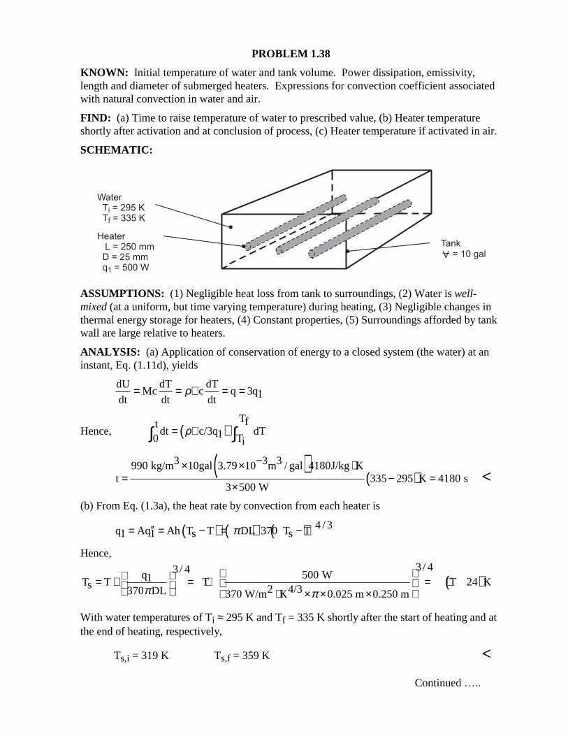
PROBLEM 1.38 KNOWN: Initial temperature of water and tank volume. Power dissipation, emissivity, length and diameter of submerged heaters. Expressions for convection coefficient associated with natural convection in water and air. FIND: (a) Time to raise temperature of water to prescribed value, (b) Heater temperature shortly after activation and at conclusion of process, (c) Heater temperature if activated in air. SCHEMATIC:
ASSUMPTIONS: (1) Negligible heat loss from tank to surroundings, (2) Water is well-mixed (at a uniform, but time varying temperature) during heating, (3) Negligible changes in thermal energy storage for heaters, (4) Constant properties, (5) Surroundings afforded by tank wall are large relative to heaters. ANALYSIS: (a) Application of conservation of energy to a closed system (the water) at an instant, Eq. (1.11d), yields
dU dT dT
Mc c q 3q1dt dt dtρ= = ∀ = =
Hence, ( )Tft
dt c/3q dT10 Tiρ= ∀∫ ∫
( )
( )3 3 3990 kg/m 10gal 3.79 10 m / gal 4180J/kg K
t 335 295 K 4180 s3 500 W
−× × ⋅= − =
× <
(b) From Eq. (1.3a), the heat rate by convection from each heater is
( ) ( ) ( )4 / 3q Aq Ah T T DL 370 T T1 1 s sπ′′= = − = − Hence,
( )3/ 43/ 4q 500 W1T T T T 24 Ks 2 4/3370 DL 370 W/m K 0.025 m 0.250 mπ π
= + = + = + ⋅ × × ×
With water temperatures of Ti ≈ 295 K and Tf = 335 K shortly after the start of heating and at the end of heating, respectively,
Ts,i = 319 K Ts,f = 359 K < Continued …..
PROBLEM 1.38 (Continued) (c) From Eq. (1.10), the heat rate in air is
( ) ( )4 / 3 4 4q DL 0.70 T T T T1 s s surπ εσ = − + −∞
Substituting the prescribed values of q1, D, L, T∞ = Tsur and ε, an iterative solution yields
Ts = 830 K < COMMENTS: In part (c) it is presumed that the heater can be operated at Ts = 830 K
without experiencing burnout. The much larger value of Ts for air is due to the smaller
convection coefficient. However, with qconv and qrad equal to 59 W and 441 W, respectively, a significant portion of the heat dissipation is effected by radiation.
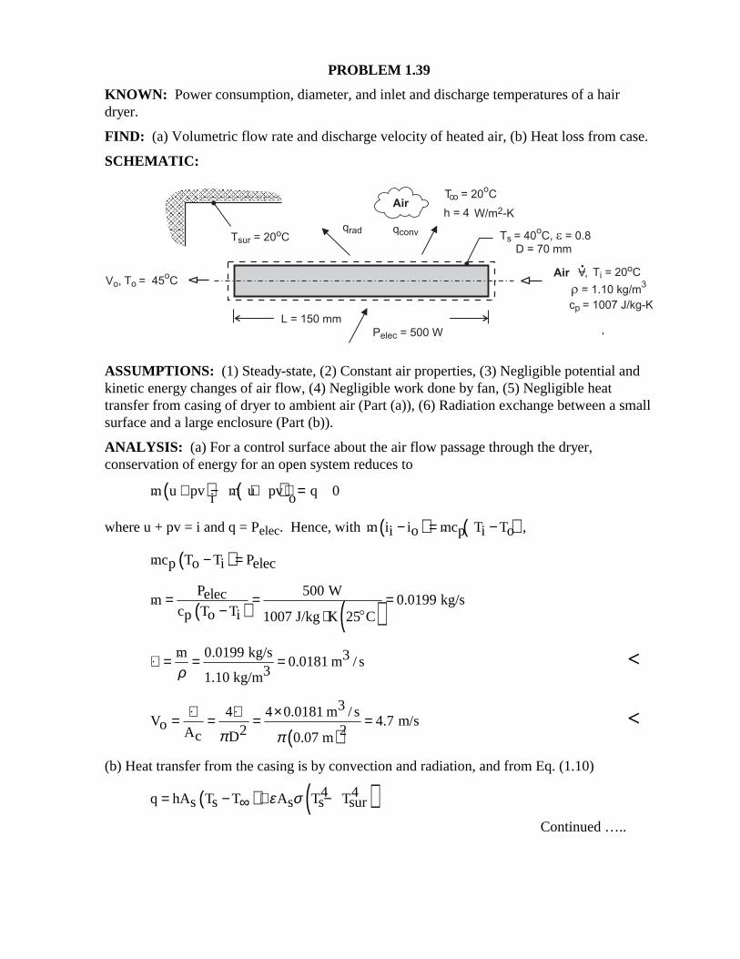
PROBLEM 1.39 KNOWN: Power consumption, diameter, and inlet and discharge temperatures of a hair dryer. FIND: (a) Volumetric flow rate and discharge velocity of heated air, (b) Heat loss from case. SCHEMATIC:
ASSUMPTIONS: (1) Steady-state, (2) Constant air properties, (3) Negligible potential and kinetic energy changes of air flow, (4) Negligible work done by fan, (5) Negligible heat transfer from casing of dryer to ambient air (Part (a)), (6) Radiation exchange between a small surface and a large enclosure (Part (b)). ANALYSIS: (a) For a control surface about the air flow passage through the dryer, conservation of energy for an open system reduces to ( ) ( )m u pv m u pv q 0i o+ − + + = where u + pv = i and q = Pelec. Hence, with ( ) ( )m i i mc T T ,i o p i o− = − ( )mc T T Pp o i elec− =
( ) ( )P 500 Welecm 0.0199 kg/s
c T Tp o i 1007 J/kg K 25 C= = =
− ⋅
$
m 0.0199 kg/s 30.0181 m / s
31.10 kg/mρ∀ = = =
<
( )
34 4 0.0181 m / sV 4.7 m/so 2 2Ac D 0.07 mπ π
∀ ∀ ×= = = =
<
(b) Heat transfer from the casing is by convection and radiation, and from Eq. (1.10)
( ) ( )4 4q hA T T A T Ts s s s surε σ= − + −∞
Continued …..
PROBLEM 1.39 (Continued)
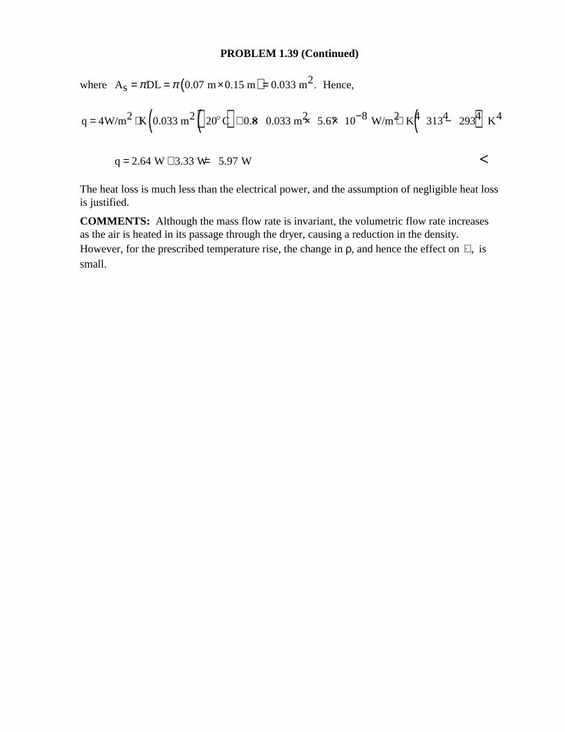
where ( ) 2A DL 0.07 m 0.15 m 0.033 m .s π π= = × = Hence,
( )( ) ( )2 2 2 8 2 4 4 4 4q 4W/m K 0.033 m 20 C 0.8 0.033 m 5.67 10 W/m K 313 293 K−= ⋅ + × × × ⋅ −$
q 2.64 W 3.33 W 5.97 W= + = < The heat loss is much less than the electrical power, and the assumption of negligible heat loss is justified. COMMENTS: Although the mass flow rate is invariant, the volumetric flow rate increases as the air is heated in its passage through the dryer, causing a reduction in the density. However, for the prescribed temperature rise, the change in ρ, and hence the effect on ,∀ is small.
PROBLEM 1.40
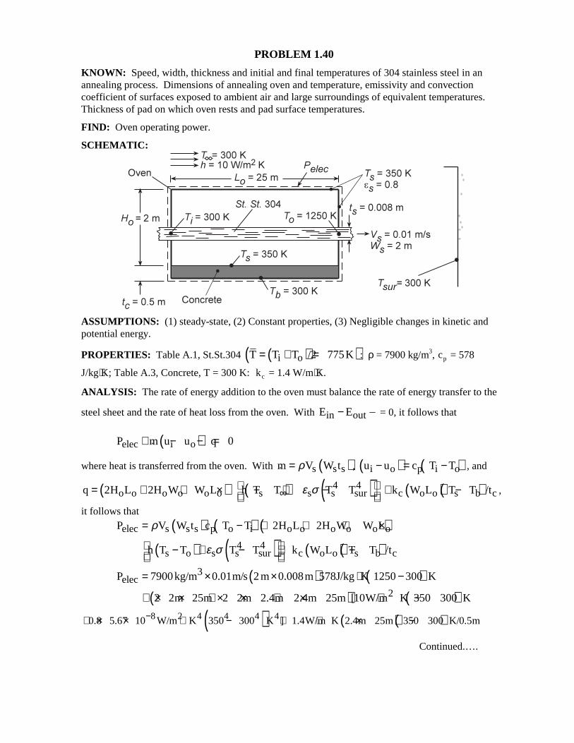
KNOWN: Speed, width, thickness and initial and final temperatures of 304 stainless steel in an annealing process. Dimensions of annealing oven and temperature, emissivity and convection coefficient of surfaces exposed to ambient air and large surroundings of equivalent temperatures. Thickness of pad on which oven rests and pad surface temperatures. FIND: Oven operating power. SCHEMATIC:
ASSUMPTIONS: (1) steady-state, (2) Constant properties, (3) Negligible changes in kinetic and potential energy. PROPERTIES: Table A.1, St.St.304 ( )( )i oT T T /2 775K= + = : ρ = 7900 kg/m3, cp = 578
J/kg⋅K; Table A.3, Concrete, T = 300 K: kc = 1.4 W/m⋅K. ANALYSIS: The rate of energy addition to the oven must balance the rate of energy transfer to the
steel sheet and the rate of heat loss from the oven. With in outE E− = 0, it follows that
( )elec i oP m u u q 0+ − − = where heat is transferred from the oven. With ( )s s sm V W tρ= , ( ) ( )i o p i ou u c T T− = − , and
( ) ( ) ( )4 4o o o o o o s s s surq 2H L 2H W W L h T T T Tε σ∞
= + + × − + − ( )( )c o o s b ck W L T T /t+ − ,
it follows that
( ) ( ) ( )elec s s s p o i o o o o o oP V W t c T T 2H L 2H W W Lρ= − + + + ×
( ) ( ) ( )( )4 4s o s s sur c o o s b ch T T T T k W L T T /tε σ − + − + −
( ) ( )3elecP 7900kg/m 0.01m/s 2m 0.008m 578J/kg K 1250 300 K= × × ⋅ −
( ) ( )22 2m 25m 2 2m 2.4m 2.4m 25m [10W/m K 350 300 K+ × × + × × + × ⋅ −
( ) ( )( )8 2 4 4 4 40.8 5.67 10 W/m K 350 300 K ] 1.4W/m K 2.4m 25m 350 300 K/0.5m−+ × × ⋅ − + ⋅ × −
Continued.….
PROBLEM 1.40 (Cont.)
( )2 2elecP 694,000W 169.6m 500 313 W/m 8400W= + + +
( )694,000 84,800 53,100 8400 W 840kW= + + + = <
COMMENTS: Of the total energy input, 83% is transferred to the steel while approximately 10%, 6% and 1% are lost by convection, radiation and conduction from the oven. The convection and radiation losses can both be reduced by adding insulation to the side and top surfaces, which would reduce the corresponding value of Ts.
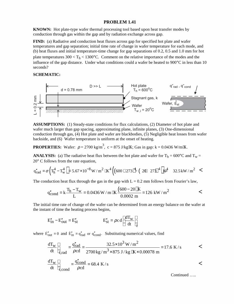
PROBLEM 1.41 KNOWN: Hot plate-type wafer thermal processing tool based upon heat transfer modes by conduction through gas within the gap and by radiation exchange across gap. FIND: (a) Radiative and conduction heat fluxes across gap for specified hot plate and wafer temperatures and gap separation; initial time rate of change in wafer temperature for each mode, and (b) heat fluxes and initial temperature-time change for gap separations of 0.2, 0.5 and 1.0 mm for hot plate temperatures 300 < Th < 1300°C. Comment on the relative importance of the modes and the influence of the gap distance. Under what conditions could a wafer be heated to 900°C in less than 10 seconds? SCHEMATIC:
ASSUMPTIONS: (1) Steady-state conditions for flux calculations, (2) Diameter of hot plate and wafer much larger than gap spacing, approximating plane, infinite planes, (3) One-dimensional conduction through gas, (4) Hot plate and wafer are blackbodies, (5) Negligible heat losses from wafer backside, and (6) Wafer temperature is uniform at the onset of heating. PROPERTIES: Wafer: ρ = 2700 kg/m
3, c = 875 J/kg⋅K; Gas in gap: k = 0.0436 W/m⋅K.
ANALYSIS: (a) The radiative heat flux between the hot plate and wafer for Th = 600°C and Tw = 20° C follows from the rate equation,
( ) ( ) ( )( )4 44 4 8 2 4 4 2rad h wq T T 5.67 10 W / m K 600 273 20 273 K 32.5kW / mσ −′′ = − × ⋅ + − + == <
The conduction heat flux through the gas in the gap with L = 0.2 mm follows from Fourier’s law,
( ) 2h w
cond600 20 KT T
q k 0.0436 W / m K 126 kW / mL 0.0002 m
−−′′ = = ⋅ = <
The initial time rate of change of the wafer can be determined from an energy balance on the wafer at the instant of time the heating process begins,
win out st st
i
dTE E E E cd
dtρ ′′ ′′ ′′ ′′− = =
where outE 0′′ = and in rad condE q or q .′′ ′′ ′′= Substituting numerical values, find
3 2
w rad3
i,rad
dT q 32.5 10 W / m17.6 K / s
dt cd 2700kg / m 875 J / kg K 0.00078 mρ′′ × = = = × ⋅ ×
<
w cond
i,cond
dT q68.4 K / s
dt cdρ′′ = =
<
Continued …..
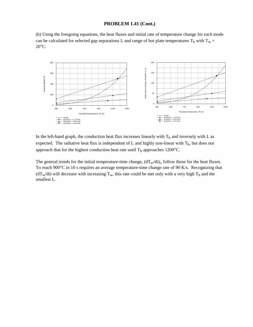
PROBLEM 1.41 (Cont.) (b) Using the foregoing equations, the heat fluxes and initial rate of temperature change for each mode
can be calculated for selected gap separations L and range of hot plate temperatures Th with Tw = 20°C.
In the left-hand graph, the conduction heat flux increases linearly with Th and inversely with L as
expected. The radiative heat flux is independent of L and highly non-linear with Th, but does not
approach that for the highest conduction heat rate until Th approaches 1200°C.
The general trends for the initial temperature-time change, (dTw/dt)i, follow those for the heat fluxes. To reach 900°C in 10 s requires an average temperature-time change rate of 90 K/s. Recognizing that (dTw/dt) will decrease with increasing Tw, this rate could be met only with a very high Th and the smallest L.
300 500 700 900 1100 1300
Hot plate temperature, Th (C)
0
100
200
300
400
He
at fl
ux (k
W/m
^2)
q''radq''cond, L = 1.0 mmq''cond, L = 0.5 mmq''cond, L = 0.2 mm
300 500 700 900 1100 1300
Hot plate temperature, Th (C)
0
50
100
150
200
Initi
al r
ate
of c
ha
ng
e, d
Tw
/dt (
K.s
^-1
)
q''radq''cond, L = 1.0 mmq''cond, L = 0.5 mmq''cond, L = 0.2 mm
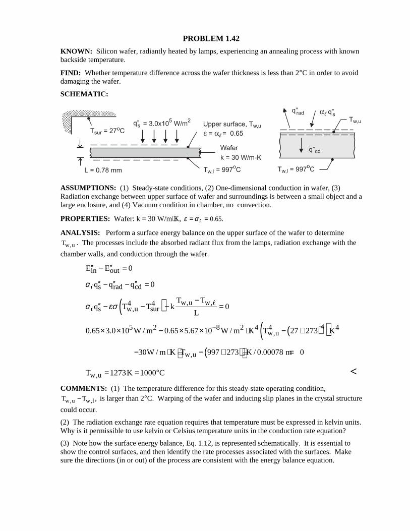
PROBLEM 1.42 KNOWN: Silicon wafer, radiantly heated by lamps, experiencing an annealing process with known backside temperature. FIND: Whether temperature difference across the wafer thickness is less than 2°C in order to avoid damaging the wafer. SCHEMATIC:
ASSUMPTIONS: (1) Steady-state conditions, (2) One-dimensional conduction in wafer, (3) Radiation exchange between upper surface of wafer and surroundings is between a small object and a large enclosure, and (4) Vacuum condition in chamber, no convection. PROPERTIES: Wafer: k = 30 W/m⋅K, 0.65.ε α= =" ANALYSIS: Perform a surface energy balance on the upper surface of the wafer to determine
w,uT . The processes include the absorbed radiant flux from the lamps, radiation exchange with the
chamber walls, and conduction through the wafer. in outE E 0′′ ′′− = s rad cdq q q 0α ′′ ′′ ′′− − ="
( ) w,u w,4 4s w,u sur
T Tq T T k 0
Lα εσ
−′′ − − − ="
"
( )( )45 2 8 2 4 4 4w,u0.65 3.0 10 W / m 0.65 5.67 10 W / m K T 27 273 K−× × − × × ⋅ − +
( )w,u30W / m K T 997 273 K / 0.00078 m 0 − ⋅ − + =
w,uT 1273K 1000 C= = ° < COMMENTS: (1) The temperature difference for this steady-state operating condition,
w,u w,lT T ,− is larger than 2°C. Warping of the wafer and inducing slip planes in the crystal structure
could occur. (2) The radiation exchange rate equation requires that temperature must be expressed in kelvin units. Why is it permissible to use kelvin or Celsius temperature units in the conduction rate equation? (3) Note how the surface energy balance, Eq. 1.12, is represented schematically. It is essential to show the control surfaces, and then identify the rate processes associated with the surfaces. Make sure the directions (in or out) of the process are consistent with the energy balance equation.
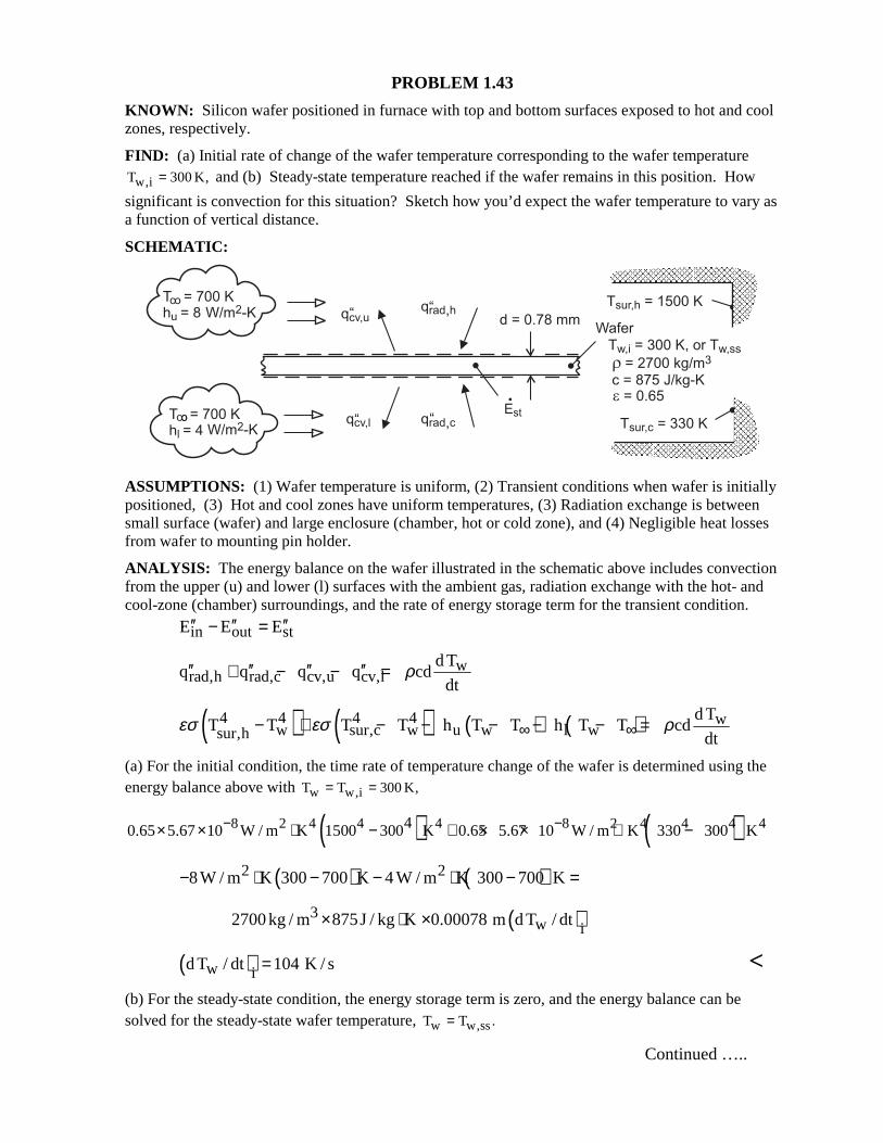
PROBLEM 1.43 KNOWN: Silicon wafer positioned in furnace with top and bottom surfaces exposed to hot and cool zones, respectively. FIND: (a) Initial rate of change of the wafer temperature corresponding to the wafer temperature
w,iT 300 K,= and (b) Steady-state temperature reached if the wafer remains in this position. How
significant is convection for this situation? Sketch how you’d expect the wafer temperature to vary as a function of vertical distance. SCHEMATIC:
ASSUMPTIONS: (1) Wafer temperature is uniform, (2) Transient conditions when wafer is initially positioned, (3) Hot and cool zones have uniform temperatures, (3) Radiation exchange is between small surface (wafer) and large enclosure (chamber, hot or cold zone), and (4) Negligible heat losses from wafer to mounting pin holder. ANALYSIS: The energy balance on the wafer illustrated in the schematic above includes convection from the upper (u) and lower (l) surfaces with the ambient gas, radiation exchange with the hot- and cool-zone (chamber) surroundings, and the rate of energy storage term for the transient condition.
in out stE E E′′ ′′ ′′− =
wrad,h rad,c cv,u cv,l
d Tq q q q cd
dtρ′′ ′′ ′′ ′′+ − − =
( ) ( ) ( ) ( )4 4 4 4 ww sur,c w u w l wsur,h
d TT T T T h T T h T T cd
dtεσ εσ ρ∞ ∞− + − − − − − =
(a) For the initial condition, the time rate of temperature change of the wafer is determined using the energy balance above with w w,iT T 300 K,= =
( ) ( )8 2 4 4 4 8 2 4 4 4 440.65 5.67 10 W / m K 1500 300 K 0.65 5.67 10 W / m K 330 300 K− −× × ⋅ − + × × ⋅ −
( ) ( )2 28W / m K 300 700 K 4 W / m K 300 700 K− ⋅ − − ⋅ − =
32700kg / m 875J / kg K× ⋅ ( )w i0.00078 m d T / dt×
( )w id T / dt 104 K / s= < (b) For the steady-state condition, the energy storage term is zero, and the energy balance can be solved for the steady-state wafer temperature, w w,ssT T .= Continued …..
PROBLEM 1.43 (Cont.)
( ) ( )4 4 4 4 4 4w,ss w,ss0.65 1500 T K 0.65 330 T Kσ σ− + −
( ) ( )2 2w,ss w,ss8W / m K T 700 K 4 W / m K T 700 K 0− ⋅ − − ⋅ − =
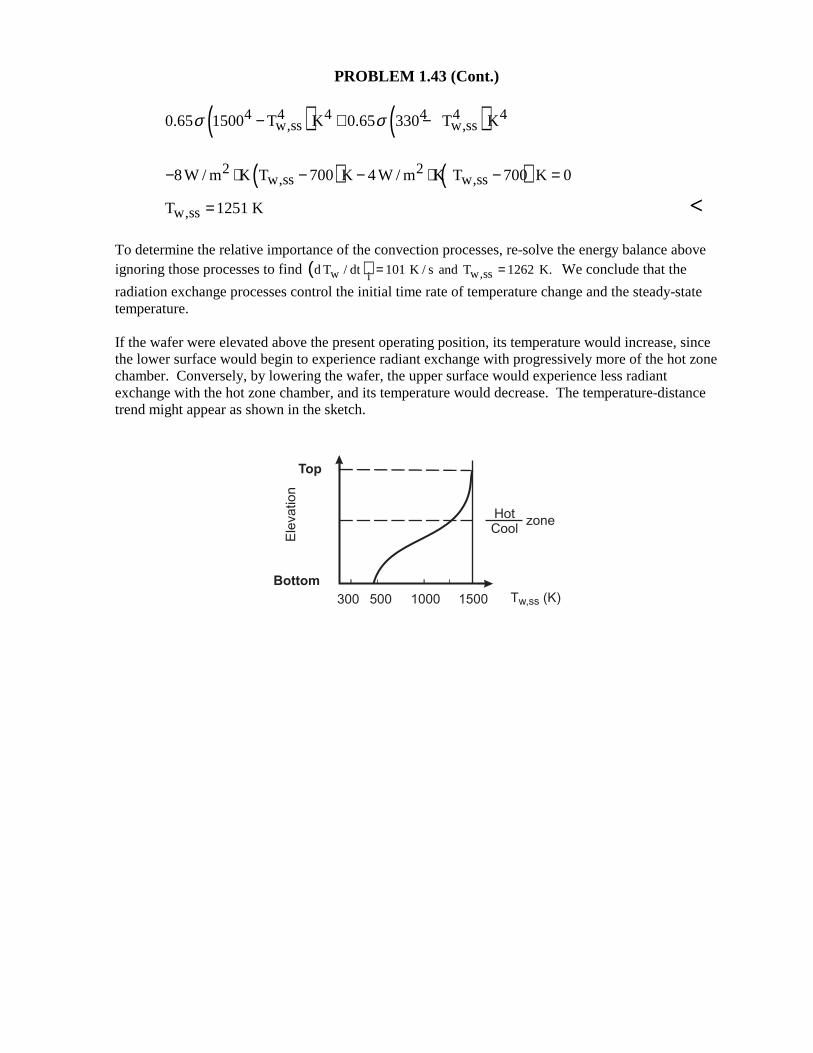
w,ssT 1251 K= <
To determine the relative importance of the convection processes, re-solve the energy balance above ignoring those processes to find ( )w w,ssid T / dt 101 K / s and T 1262 K.= = We conclude that the
radiation exchange processes control the initial time rate of temperature change and the steady-state temperature. If the wafer were elevated above the present operating position, its temperature would increase, since the lower surface would begin to experience radiant exchange with progressively more of the hot zone chamber. Conversely, by lowering the wafer, the upper surface would experience less radiant exchange with the hot zone chamber, and its temperature would decrease. The temperature-distance trend might appear as shown in the sketch.
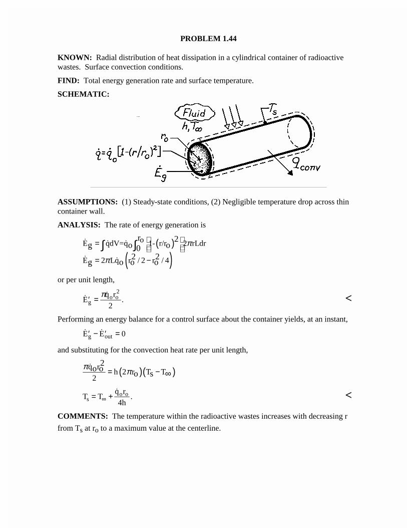
PROBLEM 1.44
KNOWN: Radial distribution of heat dissipation in a cylindrical container of radioactivewastes. Surface convection conditions.
FIND: Total energy generation rate and surface temperature.
SCHEMATIC:
ASSUMPTIONS: (1) Steady-state conditions, (2) Negligible temperature drop across thincontainer wall.
ANALYSIS: The rate of energy generation is
( )
( )oE qdV=q 1- r/r 2 rLdr
E 2 Lq r / 2 r / 4
r 2g o o0
2 2g o o o
π
π
= = −
∫ ∫
or per unit length,
.′ =Eq r
2go o
2π <
Performing an energy balance for a control surface about the container yields, at an instant,
′ − ′ =E Eg out 0
and substituting for the convection heat rate per unit length,
( )( )q rh 2 r T T
2
2o o
o sπ π= − ∞
T Tq r
4hso o= +∞
. <
COMMENTS: The temperature within the radioactive wastes increases with decreasing r
from Ts at ro to a maximum value at the centerline.
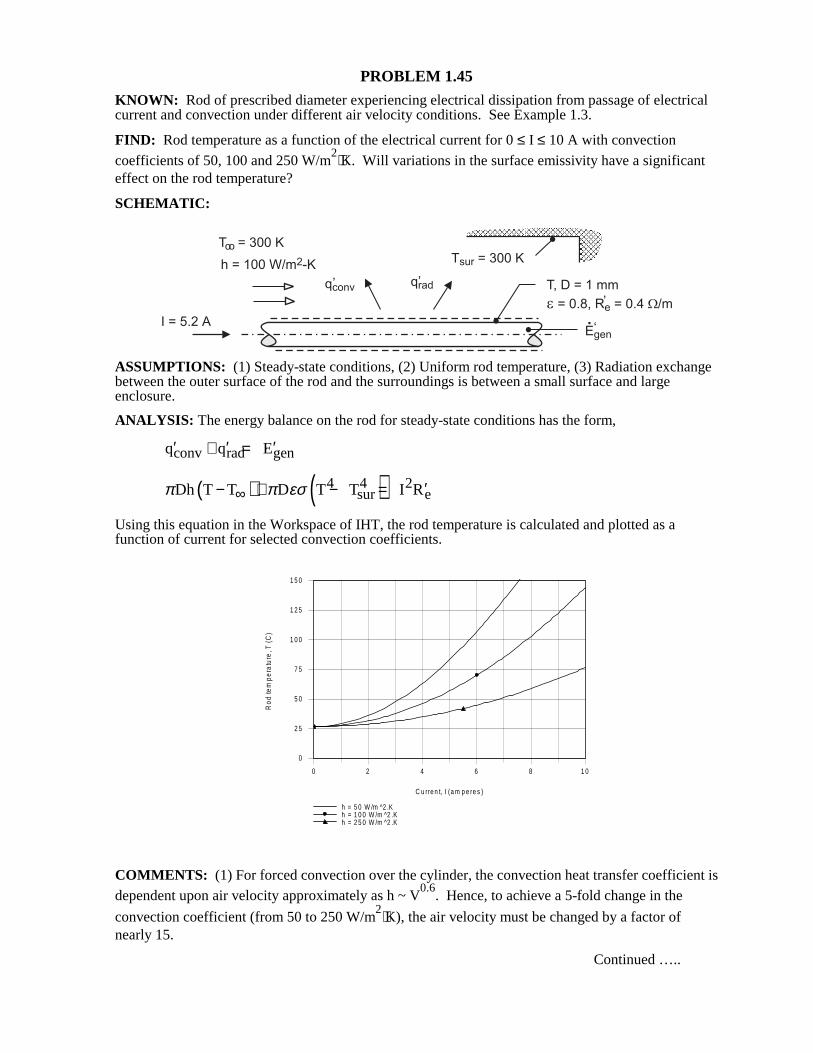
PROBLEM 1.45 KNOWN: Rod of prescribed diameter experiencing electrical dissipation from passage of electrical current and convection under different air velocity conditions. See Example 1.3. FIND: Rod temperature as a function of the electrical current for 0 ≤ I ≤ 10 A with convection
coefficients of 50, 100 and 250 W/m2⋅K. Will variations in the surface emissivity have a significant
effect on the rod temperature? SCHEMATIC:
ASSUMPTIONS: (1) Steady-state conditions, (2) Uniform rod temperature, (3) Radiation exchange between the outer surface of the rod and the surroundings is between a small surface and large enclosure. ANALYSIS: The energy balance on the rod for steady-state conditions has the form, conv rad genq q E′ ′ ′+ =
( ) ( )4 4 2sur eDh T T D T T I Rπ π εσ∞ ′− + − =
Using this equation in the Workspace of IHT, the rod temperature is calculated and plotted as a function of current for selected convection coefficients. COMMENTS: (1) For forced convection over the cylinder, the convection heat transfer coefficient is dependent upon air velocity approximately as h ~ V
0.6. Hence, to achieve a 5-fold change in the
convection coefficient (from 50 to 250 W/m2⋅K), the air velocity must be changed by a factor of
nearly 15. Continued …..
0 2 4 6 8 1 0
C u rre n t, I (a m p e re s )
0
2 5
5 0
7 5
1 0 0
1 2 5
1 5 0
Ro
d te
mpe
ratu
re, T
(C)
h = 5 0 W /m ^2 .Kh = 1 0 0 W /m ^2 .Kh = 2 5 0 W /m ^2 .K
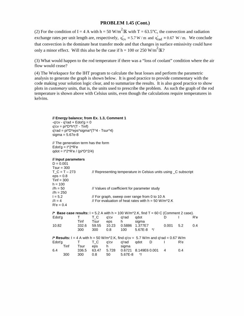
PROBLEM 1.45 (Cont.) (2) For the condition of I = 4 A with h = 50 W/m
2⋅K with T = 63.5°C, the convection and radiation exchange rates per unit length are, respectively, cv radq 5.7 W / m and q 0.67 W / m.′ ′= = We conclude
that convection is the dominate heat transfer mode and that changes in surface emissivity could have
only a minor effect. Will this also be the case if h = 100 or 250 W/m2⋅K?
(3) What would happen to the rod temperature if there was a “loss of coolant” condition where the air flow would cease? (4) The Workspace for the IHT program to calculate the heat losses and perform the parametric analysis to generate the graph is shown below. It is good practice to provide commentary with the code making your solution logic clear, and to summarize the results. It is also good practice to show plots in customary units, that is, the units used to prescribe the problem. As such the graph of the rod temperature is shown above with Celsius units, even though the calculations require temperatures in kelvins.
// Energy balance; from Ex. 1.3, Comment 1 -q'cv - q'rad + Edot'g = 0 q'cv = pi*D*h*(T - Tinf) q'rad = pi*D*eps*sigma*(T^4 - Tsur^4) sigma = 5.67e-8 // The generation term has the form Edot'g = I^2*R'e qdot = I^2*R'e / (pi*D^2/4) // Input parameters D = 0.001 Tsur = 300 T_C = T – 273 // Representing temperature in Celsius units using _C subscript eps = 0.8 Tinf = 300 h = 100 //h = 50 // Values of coefficient for parameter study //h = 250 I = 5.2 // For graph, sweep over range from 0 to 10 A //I = 4 // For evaluation of heat rates with h = 50 W/m^2.K R'e = 0.4 /* Base case results: I = 5.2 A with h = 100 W/m^2.K, find T = 60 C (Comment 2 case). Edot'g T T_C q'cv q'rad qdot D I R'e
Tinf Tsur eps h sigma 10.82 332.6 59.55 10.23 0.5886 1.377E7 0.001 5.2 0.4 300 300 0.8 100 5.67E-8 */ /* Results: I = 4 A with h = 50 W/m^2.K, find q'cv = 5.7 W/m and q'rad = 0.67 W/m Edot'g T T_C q'cv q'rad qdot D I R'e Tinf Tsur eps h sigma 6.4 336.5 63.47 5.728 0.6721 8.149E6 0.001 4 0.4 300 300 0.8 50 5.67E-8 */
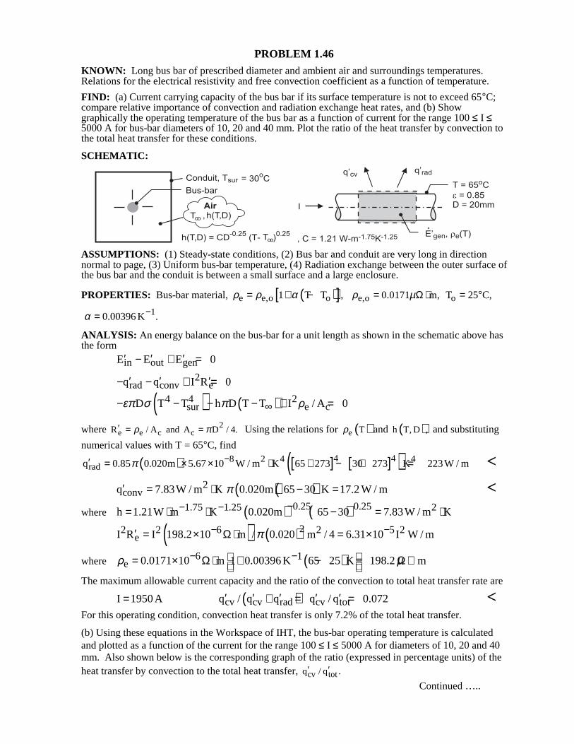
PROBLEM 1.46 KNOWN: Long bus bar of prescribed diameter and ambient air and surroundings temperatures. Relations for the electrical resistivity and free convection coefficient as a function of temperature. FIND: (a) Current carrying capacity of the bus bar if its surface temperature is not to exceed 65°C; compare relative importance of convection and radiation exchange heat rates, and (b) Show graphically the operating temperature of the bus bar as a function of current for the range 100 ≤ I ≤ 5000 A for bus-bar diameters of 10, 20 and 40 mm. Plot the ratio of the heat transfer by convection to the total heat transfer for these conditions. SCHEMATIC:
ASSUMPTIONS: (1) Steady-state conditions, (2) Bus bar and conduit are very long in direction normal to page, (3) Uniform bus-bar temperature, (4) Radiation exchange between the outer surface of the bus bar and the conduit is between a small surface and a large enclosure. PROPERTIES: Bus-bar material, ( )[ ]e e,o o1 T T ,ρ ρ α= + − e,o 0.0171 m,ρ µ= Ω ⋅ oT 25 C,= °
10.00396 K .α −= ANALYSIS: An energy balance on the bus-bar for a unit length as shown in the schematic above has the form in out genE E E 0′ ′ ′− + =
2rad conv eq q I R 0′ ′ ′− − + =
( ) ( )4 4 2sur e cD T T h D T T I / A 0επ σ π ρ∞− − − − + =
where 2e e c cR / A and A D / 4.ρ π′ = = Using the relations for ( )e Tρ and ( )h T, D , and substituting
numerical values with T = 65°C, find
( ) [ ] [ ]( )4 48 2 4 4radq 0.85 0.020m 5.67 10 W / m K 65 273 30 273 K 223W / mπ −′ = × × ⋅ + − + = <
( )( )2convq 7.83W / m K 0.020m 65 30 K 17.2 W / mπ′ = ⋅ − = <
where ( ) ( )0.25 0.251.75 1.25 2h 1.21W m K 0.020m 65 30 7.83W / m K−− −= ⋅ ⋅ − = ⋅
( ) ( )22 2 6 2 5 2eI R I 198.2 10 m / 0.020 m / 4 6.31 10 I W / mπ− −′ = × Ω⋅ = ×
where ( )6 1e 0.0171 10 m 1 0.00396K 65 25 K 198.2 mρ µ− − = × Ω⋅ + − = Ω⋅
The maximum allowable current capacity and the ratio of the convection to total heat transfer rate are
( )cv cv rad cv totI 1950A q / q q q / q 0.072′ ′ ′ ′ ′= + = = <
For this operating condition, convection heat transfer is only 7.2% of the total heat transfer. (b) Using these equations in the Workspace of IHT, the bus-bar operating temperature is calculated and plotted as a function of the current for the range 100 ≤ I ≤ 5000 A for diameters of 10, 20 and 40 mm. Also shown below is the corresponding graph of the ratio (expressed in percentage units) of the heat transfer by convection to the total heat transfer, cv totq / q .′ ′
Continued …..
PROBLEM 1.46 (Cont.)
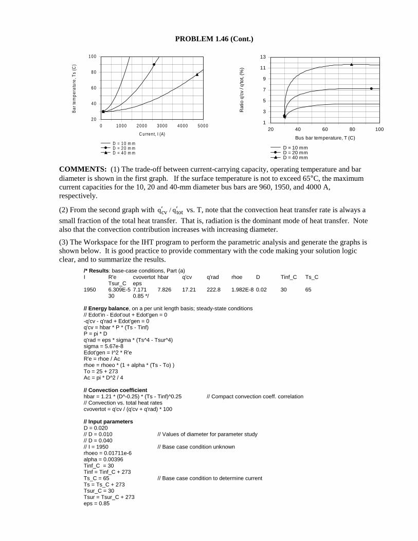
COMMENTS: (1) The trade-off between current-carrying capacity, operating temperature and bar diameter is shown in the first graph. If the surface temperature is not to exceed 65°C, the maximum current capacities for the 10, 20 and 40-mm diameter bus bars are 960, 1950, and 4000 A, respectively. (2) From the second graph with cv totq / q′ ′ vs. T, note that the convection heat transfer rate is always a
small fraction of the total heat transfer. That is, radiation is the dominant mode of heat transfer. Note also that the convection contribution increases with increasing diameter. (3) The Workspace for the IHT program to perform the parametric analysis and generate the graphs is shown below. It is good practice to provide commentary with the code making your solution logic clear, and to summarize the results.
/* Results : base-case conditions, Part (a) I R'e cvovertot hbar q'cv q'rad rhoe D Tinf_C Ts_C Tsur_C eps 1950 6.309E-5 7.171 7.826 17.21 222.8 1.982E-8 0.02 30 65 30 0.85 */ // Energy balance , on a per unit length basis; steady-state conditions // Edot'in - Edot'out + Edot'gen = 0 -q'cv - q'rad + Edot'gen = 0 q'cv = hbar * P * (Ts - Tinf) P = pi * D q'rad = eps * sigma * (Ts^4 - Tsur^4) sigma = 5.67e-8 Edot'gen = I^2 * R'e R'e = rhoe / Ac rhoe = rhoeo * (1 + alpha * (Ts - To) ) To = 25 + 273 Ac = pi * D^2 / 4 // Convection coefficient hbar = 1.21 * (D^-0.25) * (Ts - Tinf)^0.25 // Compact convection coeff. correlation // Convection vs. total heat rates cvovertot = q'cv / (q'cv + q'rad) * 100 // Input parameters D = 0.020 // D = 0.010 // Values of diameter for parameter study // D = 0.040 // I = 1950 // Base case condition unknown rhoeo = 0.01711e-6 alpha = 0.00396 Tinf_C = 30 Tinf = Tinf_C + 273 Ts_C = 65 // Base case condition to determine current Ts = Ts_C + 273 Tsur_C = 30 Tsur = Tsur_C + 273 eps = 0.85
0 1 0 0 0 2 0 0 0 3 0 0 0 4 0 0 0 5 0 0 0
C u rren t, I (A)
2 0
4 0
6 0
8 0
1 0 0
Bar
tem
pera
ture
, Ts
(C)
D = 1 0 m mD = 2 0 m mD = 4 0 m m
20 40 60 80 100
Bus bar temperature, T (C)
1
3
5
7
9
11
13
Ra
tio q
'cv
/ q'to
t, (%
)
D = 10 mmD = 20 mmD = 40 mm
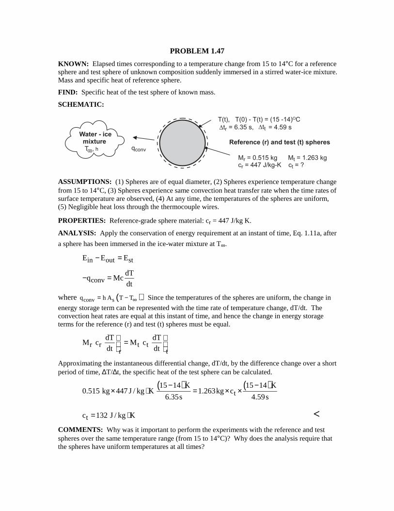
PROBLEM 1.47 KNOWN: Elapsed times corresponding to a temperature change from 15 to 14°C for a reference sphere and test sphere of unknown composition suddenly immersed in a stirred water-ice mixture. Mass and specific heat of reference sphere. FIND: Specific heat of the test sphere of known mass. SCHEMATIC:
ASSUMPTIONS: (1) Spheres are of equal diameter, (2) Spheres experience temperature change from 15 to 14°C, (3) Spheres experience same convection heat transfer rate when the time rates of surface temperature are observed, (4) At any time, the temperatures of the spheres are uniform, (5) Negligible heat loss through the thermocouple wires. PROPERTIES: Reference-grade sphere material: cr = 447 J/kg K. ANALYSIS: Apply the conservation of energy requirement at an instant of time, Eq. 1.11a, after
a sphere has been immersed in the ice-water mixture at T∞. in out stE E E− =
convdT
q Mcdt
− =
where ( )conv sq h A T T .∞= − Since the temperatures of the spheres are uniform, the change in
energy storage term can be represented with the time rate of temperature change, dT/dt. The convection heat rates are equal at this instant of time, and hence the change in energy storage terms for the reference (r) and test (t) spheres must be equal.
r r t tr t
dT dTM c M c
dt dt =
Approximating the instantaneous differential change, dT/dt, by the difference change over a short period of time, ∆T/∆t, the specific heat of the test sphere can be calculated.
( ) ( )
t15 14 K 15 14 K
0.515 kg 447 J / kg K 1.263kg c6.35s 4.59s
− −× ⋅ = × ×
tc 132 J / kg K= ⋅ < COMMENTS: Why was it important to perform the experiments with the reference and test spheres over the same temperature range (from 15 to 14°C)? Why does the analysis require that the spheres have uniform temperatures at all times?
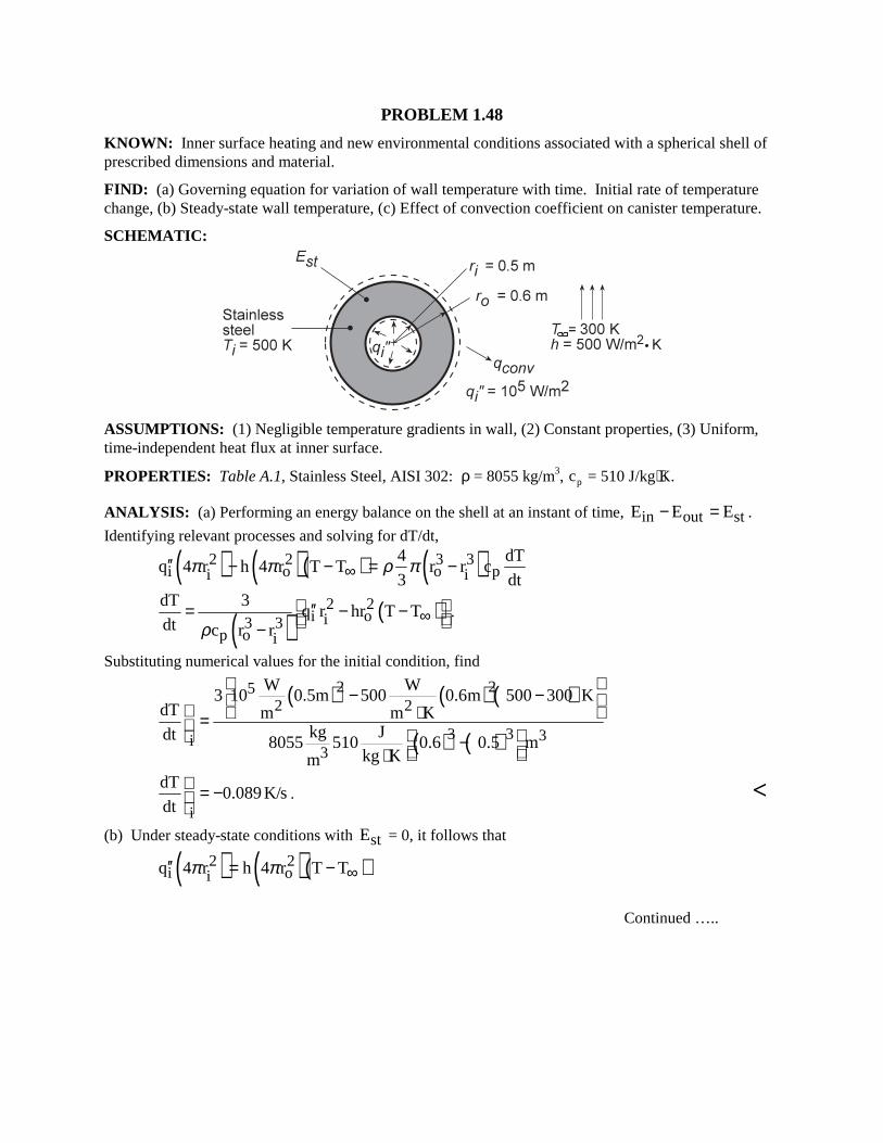
PROBLEM 1.48 KNOWN: Inner surface heating and new environmental conditions associated with a spherical shell of prescribed dimensions and material. FIND: (a) Governing equation for variation of wall temperature with time. Initial rate of temperature change, (b) Steady-state wall temperature, (c) Effect of convection coefficient on canister temperature. SCHEMATIC:
ASSUMPTIONS: (1) Negligible temperature gradients in wall, (2) Constant properties, (3) Uniform, time-independent heat flux at inner surface. PROPERTIES: Table A.1, Stainless Steel, AISI 302: ρ = 8055 kg/m3, cp = 510 J/kg⋅K. ANALYSIS: (a) Performing an energy balance on the shell at an instant of time, in out stE E E− = .
Identifying relevant processes and solving for dT/dt,
( ) ( )( ) ( )2 2 3 3i o o pi i
4 dTq 4 r h 4 r T T r r c
3 dtπ π ρ π∞′′ − − = −
( ) ( )2 2i oi3 3
p o i
dT 3q r hr T T
dt c r rρ∞ ′′= − − −
.
Substituting numerical values for the initial condition, find
( ) ( ) ( )
( ) ( )
2 252 2
3 3 3i3
W W3 10 0.5m 500 0.6m 500 300 K
dT m m Kkg Jdt 8055 510 0.6 0.5 m
kg Km
− − ⋅ = − ⋅
i
dT0.089K/s
dt = −
. <
(b) Under steady-state conditions with stE = 0, it follows that
( ) ( )( )2 2i oiq 4 r h 4 r T Tπ π ∞′′ = −
Continued …..
PROBLEM 1.48 (Cont.)
2 25 2i i
2o
q r 10 W/m 0.5mT T 300K 439K
h r 0.6m500W/m K∞
′′ = + = + = ⋅ <
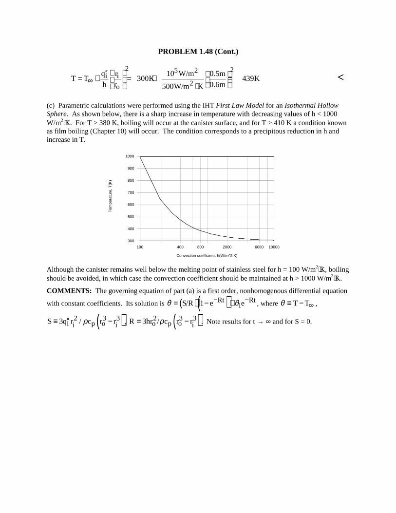
(c) Parametric calculations were performed using the IHT First Law Model for an Isothermal Hollow Sphere. As shown below, there is a sharp increase in temperature with decreasing values of h < 1000 W/m2⋅K. For T > 380 K, boiling will occur at the canister surface, and for T > 410 K a condition known as film boiling (Chapter 10) will occur. The condition corresponds to a precipitous reduction in h and increase in T.
100 400 800 2000 6000 10000
Convection coefficient, h(W/m^2.K)
300
400
500
600
700
800
900
1000
Tem
pera
ture
, T(K
)
Although the canister remains well below the melting point of stainless steel for h = 100 W/m2⋅K, boiling should be avoided, in which case the convection coefficient should be maintained at h > 1000 W/m2⋅K. COMMENTS: The governing equation of part (a) is a first order, nonhomogenous differential equation
with constant coefficients. Its solution is ( )( )Rt RtiS/R 1 e eθ θ− −= − + , where T Tθ ∞≡ − ,
( )2 3 3i p oi iS 3q r / c r rρ′′≡ − , ( )2 3 3
o p o iR 3hr / c r rρ= − . Note results for t → ∞ and for S = 0.
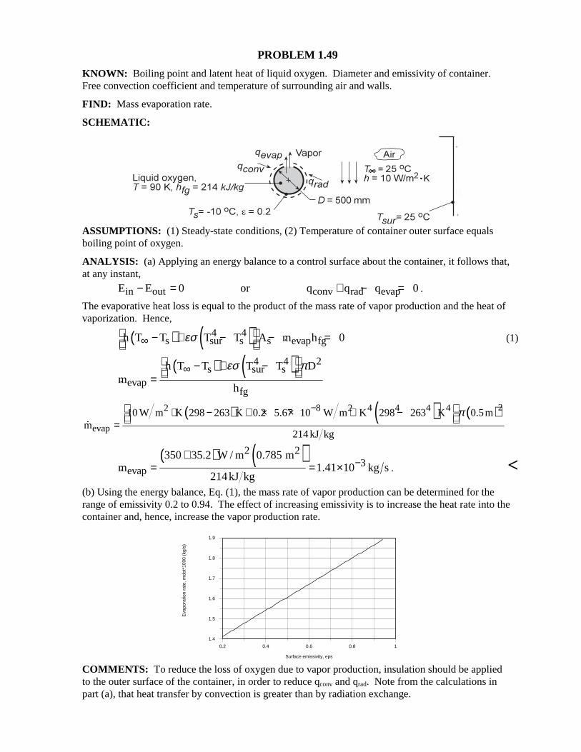
PROBLEM 1.49 KNOWN: Boiling point and latent heat of liquid oxygen. Diameter and emissivity of container. Free convection coefficient and temperature of surrounding air and walls. FIND: Mass evaporation rate. SCHEMATIC:
ASSUMPTIONS: (1) Steady-state conditions, (2) Temperature of container outer surface equals boiling point of oxygen. ANALYSIS: (a) Applying an energy balance to a control surface about the container, it follows that, at any instant,
in out conv rad evapE E 0 or q q q 0− = + − = .
The evaporative heat loss is equal to the product of the mass rate of vapor production and the heat of vaporization. Hence,
( ) ( )4 4s sur s s evap fgh T T T T A m h 0εσ∞
− + − − = (1)
( ) ( )4 4 2
s sur sevap
fg
h T T T T Dm
h
εσ π∞ − + − =
( ) ( ) ( )22 8 2 4 4 4 4
evap
10 W m K 298 263 K 0.2 5.67 10 W m K 298 263 K 0.5mm
214 kJ kg
π−⋅ − + × × ⋅ −=
( ) ( )2 2
3evap
350 35.2 W / m 0.785 mm 1.41 10 kg s
214kJ kg−
+= = × . <
(b) Using the energy balance, Eq. (1), the mass rate of vapor production can be determined for the range of emissivity 0.2 to 0.94. The effect of increasing emissivity is to increase the heat rate into the container and, hence, increase the vapor production rate.
0.2 0.4 0.6 0.8 1
Surface emissivity, eps
1.4
1.5
1.6
1.7
1.8
1.9
Eva
pora
tion
rate
, mdo
t*10
00 (
kg/s
)
COMMENTS: To reduce the loss of oxygen due to vapor production, insulation should be applied to the outer surface of the container, in order to reduce qconv and qrad. Note from the calculations in part (a), that heat transfer by convection is greater than by radiation exchange.
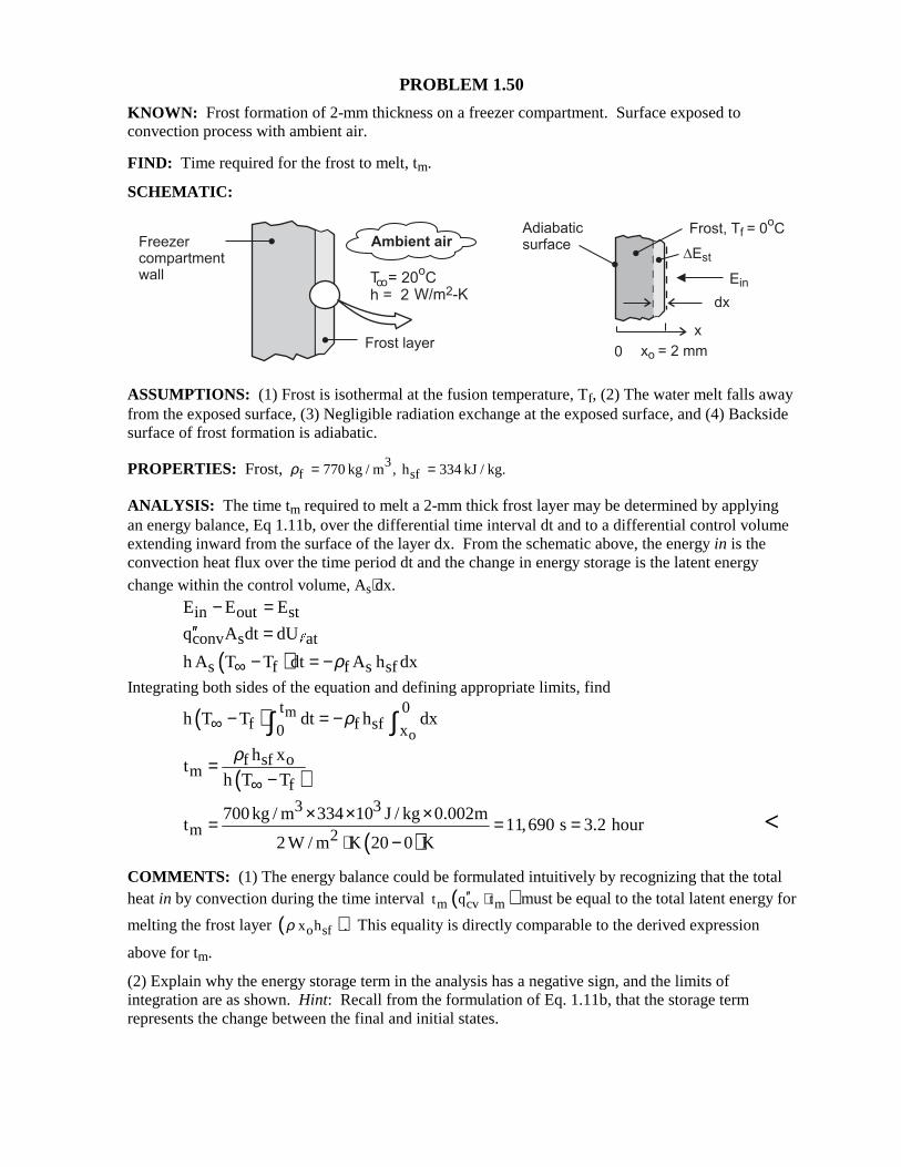
PROBLEM 1.50 KNOWN: Frost formation of 2-mm thickness on a freezer compartment. Surface exposed to convection process with ambient air. FIND: Time required for the frost to melt, tm. SCHEMATIC:
ASSUMPTIONS: (1) Frost is isothermal at the fusion temperature, Tf, (2) The water melt falls away from the exposed surface, (3) Negligible radiation exchange at the exposed surface, and (4) Backside surface of frost formation is adiabatic.
PROPERTIES: Frost, 3f sf770 kg / m , h 334 kJ / kg.ρ = =
ANALYSIS: The time tm required to melt a 2-mm thick frost layer may be determined by applying an energy balance, Eq 1.11b, over the differential time interval dt and to a differential control volume extending inward from the surface of the layer dx. From the schematic above, the energy in is the convection heat flux over the time period dt and the change in energy storage is the latent energy change within the control volume, As⋅dx. in out stE E E− =
conv s atq A dt dU′′ = "
( )s f f s sfh A T T dt A h dxρ∞ − = −
Integrating both sides of the equation and defining appropriate limits, find
( ) m
o
t 0f f sf0 x
h T T dt h dxρ∞ − = −∫ ∫
( )f sf o
mf
h xt
h T T
ρ
∞=
−
( )
3 3
m 2700kg / m 334 10 J / kg 0.002m
t 11,690 s 3.2 hour2 W / m K 20 0 K
× × ×= = =⋅ −
<
COMMENTS: (1) The energy balance could be formulated intuitively by recognizing that the total heat in by convection during the time interval ( )m cv mt q t′′ ⋅ must be equal to the total latent energy for
melting the frost layer ( )o sfx h .ρ This equality is directly comparable to the derived expression
above for tm. (2) Explain why the energy storage term in the analysis has a negative sign, and the limits of integration are as shown. Hint: Recall from the formulation of Eq. 1.11b, that the storage term represents the change between the final and initial states.
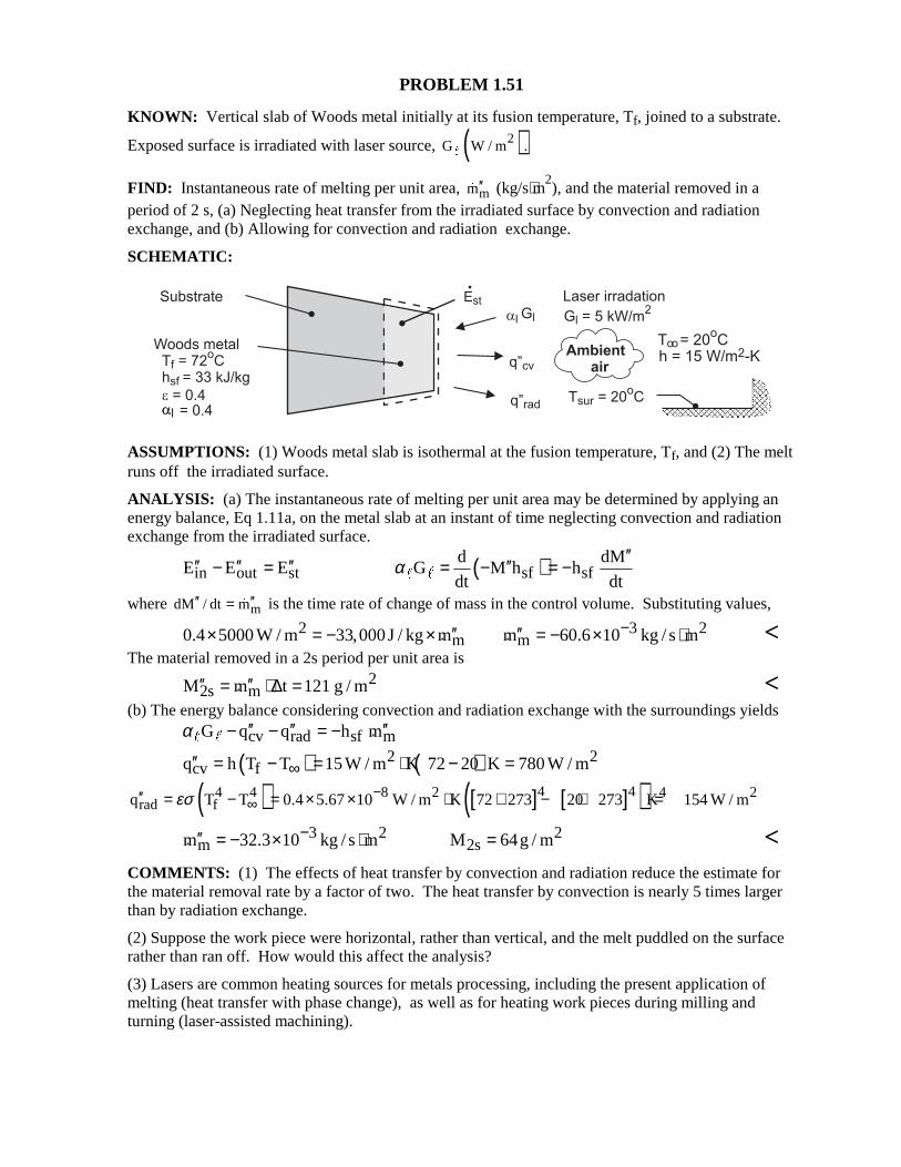
PROBLEM 1.51 KNOWN: Vertical slab of Woods metal initially at its fusion temperature, Tf, joined to a substrate.
Exposed surface is irradiated with laser source, ( )2G W / m ." FIND: Instantaneous rate of melting per unit area, mm′′
(kg/s⋅m2), and the material removed in a
period of 2 s, (a) Neglecting heat transfer from the irradiated surface by convection and radiation exchange, and (b) Allowing for convection and radiation exchange. SCHEMATIC:
ASSUMPTIONS: (1) Woods metal slab is isothermal at the fusion temperature, Tf, and (2) The melt runs off the irradiated surface. ANALYSIS: (a) The instantaneous rate of melting per unit area may be determined by applying an energy balance, Eq 1.11a, on the metal slab at an instant of time neglecting convection and radiation exchange from the irradiated surface.
in out stE E E′′ ′′ ′′− = ( )sf sfd dM
G M h hdt dt
α′′′′= − = −" "
where mdM / dt m′′ ′′= is the time rate of change of mass in the control volume. Substituting values,
2 3 2m m0.4 5000 W / m 33,000J / kg m m 60.6 10 kg / s m−′′ ′′× = − × = − × ⋅ <
The material removed in a 2s period per unit area is
22s mM m t 121 g / m′′ ′′= ⋅ ∆ = <
(b) The energy balance considering convection and radiation exchange with the surroundings yields cv rad sf mG q q h mα ′′ ′′ ′′− − = −" "
( ) ( )2 2cv fq h T T 15W / m K 72 20 K 780 W / m∞′′ = − = ⋅ − =
( ) [ ] [ ]( )4 44 4 8 2 4 2rad fq T T 0.4 5.67 10 W / m K 72 273 20 273 K 154 W / mεσ −
∞′′ = − = × × ⋅ + − + =
3 2 2m 2sm 32.3 10 kg / s m M 64g / m−′′ = − × ⋅ = <
COMMENTS: (1) The effects of heat transfer by convection and radiation reduce the estimate for the material removal rate by a factor of two. The heat transfer by convection is nearly 5 times larger than by radiation exchange. (2) Suppose the work piece were horizontal, rather than vertical, and the melt puddled on the surface rather than ran off. How would this affect the analysis? (3) Lasers are common heating sources for metals processing, including the present application of melting (heat transfer with phase change), as well as for heating work pieces during milling and turning (laser-assisted machining).
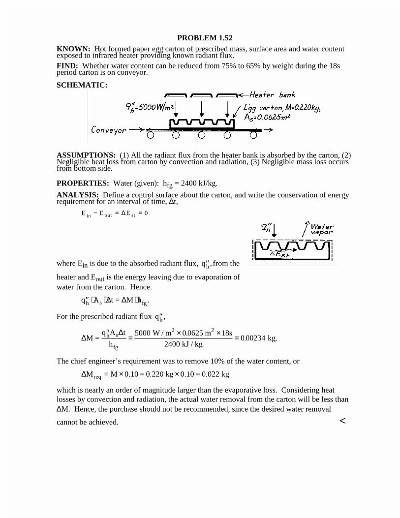
PROBLEM 1.52KNOWN: Hot formed paper egg carton of prescribed mass, surface area and water contentexposed to infrared heater providing known radiant flux.FIND: Whether water content can be reduced from 75% to 65% by weight during the 18speriod carton is on conveyor.
SCHEMATIC:
ASSUMPTIONS: (1) All the radiant flux from the heater bank is absorbed by the carton, (2)Negligible heat loss from carton by convection and radiation, (3) Negligible mass loss occursfrom bottom side.
PROPERTIES: Water (given): hfg = 2400 kJ/kg.
ANALYSIS: Define a control surface about the carton, and write the conservation of energyrequirement for an interval of time, ∆t,
E E Ein out st− = =∆ 0
where Ein is due to the absorbed radiant flux, ′′qh , from the
heater and Eout is the energy leaving due to evaporation ofwater from the carton. Hence.
′′ ⋅ ⋅ ⋅q A t = M hh s fg∆ ∆ .
For the prescribed radiant flux ′′qh ,
∆∆
M =q A t
h
W / m m s
2400 kJ / kg kg.h s
fg
2 2′′= × × =5000 0 0625 18
0 00234.
.
The chief engineer’s requirement was to remove 10% of the water content, or
∆M M 0.10 = 0.220 kg 0.10 = 0.022 kgreq = × ×
which is nearly an order of magnitude larger than the evaporative loss. Considering heatlosses by convection and radiation, the actual water removal from the carton will be less than∆M. Hence, the purchase should not be recommended, since the desired water removal
cannot be achieved. <
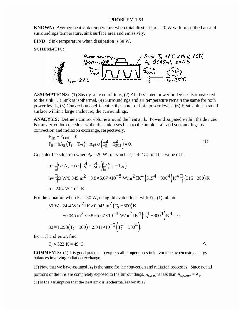
PROBLEM 1.53
KNOWN: Average heat sink temperature when total dissipation is 20 W with prescribed air andsurroundings temperature, sink surface area and emissivity.
FIND: Sink temperature when dissipation is 30 W.
SCHEMATIC:
ASSUMPTIONS: (1) Steady-state conditions, (2) All dissipated power in devices is transferredto the sink, (3) Sink is isothermal, (4) Surroundings and air temperature remain the same for bothpower levels, (5) Convection coefficient is the same for both power levels, (6) Heat sink is a smallsurface within a large enclosure, the surroundings.
ANALYSIS: Define a control volume around the heat sink. Power dissipated within the devicesis transferred into the sink, while the sink loses heat to the ambient air and surroundings byconvection and radiation exchange, respectively.
( ) ( )E E 0
P hA T T A T T 0.outin
4 4e s s s s surεσ
− =− − − − =∞
(1)
Consider the situation when Pe = 20 W for which Ts = 42°C; find the value of h.
( ) ( )h= P / A T T / T T4 4e s s sur sεσ − − − ∞
( ) ( )2h= 20 W/0.045 m 0.8 5.67 10 W/m K 315 300 K / 315 300 K8 2 4 4 4 4 − × × ⋅ − − −
h = 24.4 W / m K.2 ⋅
For the situation when Pe = 30 W, using this value for h with Eq. (1), obtain
( )30 W - 24.4 W/m K 0.045 m T 300 K2 2s⋅ × −
( )0.045 m 0.8 5.67 10 W/m K T 300 K 02 8 2 4 4 4 4s− × × × ⋅ − =−
( ) ( )30 1.098 T 300 2.041 10 T 300 .9 4 4s s= − + × −−
By trial-and-error, find
T K = 49 C.s ≈ 322 $ <COMMENTS: (1) It is good practice to express all temperatures in kelvin units when using energybalances involving radiation exchange.
(2) Note that we have assumed As is the same for the convection and radiation processes. Since not all
portions of the fins are completely exposed to the surroundings, As,rad is less than As,conv = As.
(3) Is the assumption that the heat sink is isothermal reasonable?
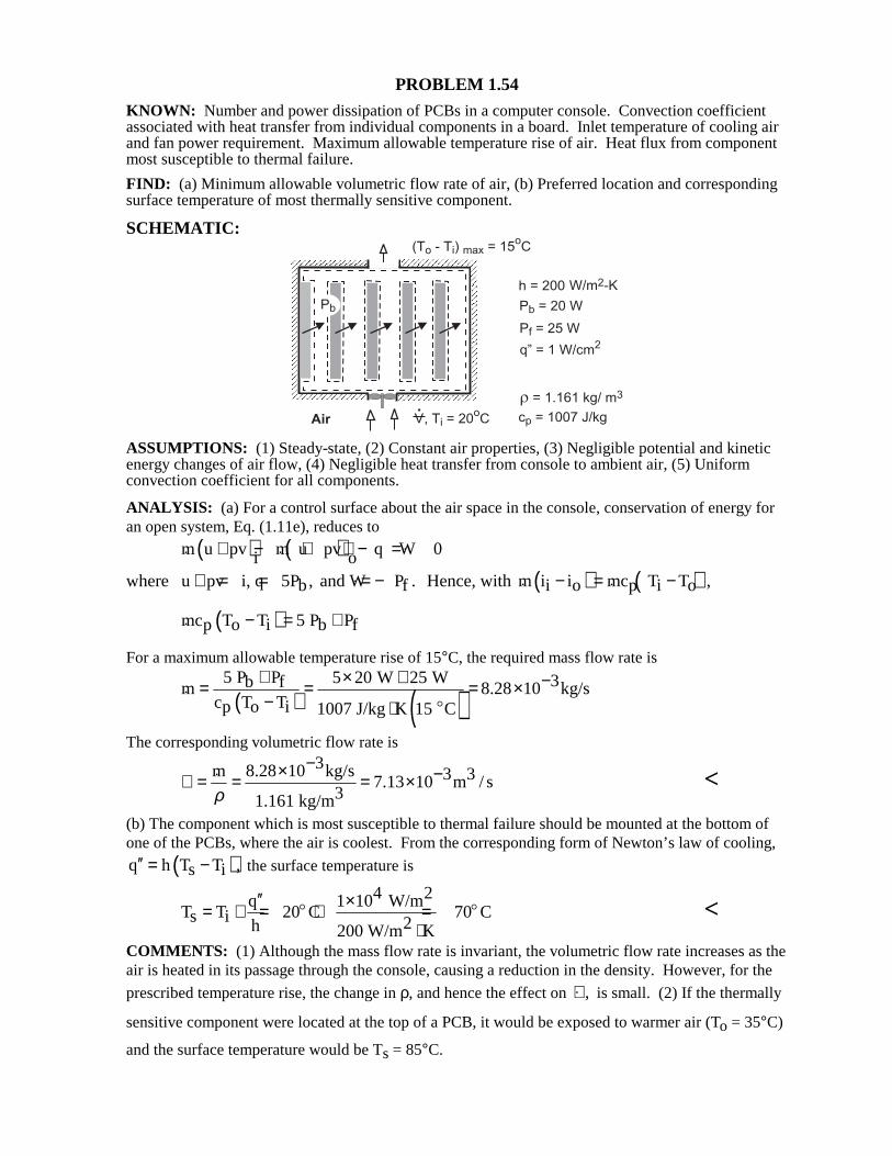
PROBLEM 1.54 KNOWN: Number and power dissipation of PCBs in a computer console. Convection coefficient associated with heat transfer from individual components in a board. Inlet temperature of cooling air and fan power requirement. Maximum allowable temperature rise of air. Heat flux from component most susceptible to thermal failure. FIND: (a) Minimum allowable volumetric flow rate of air, (b) Preferred location and corresponding surface temperature of most thermally sensitive component. SCHEMATIC:
ASSUMPTIONS: (1) Steady-state, (2) Constant air properties, (3) Negligible potential and kinetic energy changes of air flow, (4) Negligible heat transfer from console to ambient air, (5) Uniform convection coefficient for all components. ANALYSIS: (a) For a control surface about the air space in the console, conservation of energy for an open system, Eq. (1.11e), reduces to
( ) ( )m u pv m u pv q W 0i o+ − + + − =
where u pv i, q 5P , and W P .b f+ = = = − Hence, with ( ) ( )m i i mc T T ,i o p i o− = − ( )mc T T 5 P Pp o i b f− = + For a maximum allowable temperature rise of 15°C, the required mass flow rate is
( ) ( )
5 P P 5 20 W 25 W 3b fm 8.28 10 kg/sc T Tp o i 1007 J/kg K 15 C
+ × + −= = = ×− ⋅
$
The corresponding volumetric flow rate is
3m 8.28 10 kg/s 3 37.13 10 m / s
31.161 kg/mρ
−× −∀ = = = ×
<
(b) The component which is most susceptible to thermal failure should be mounted at the bottom of one of the PCBs, where the air is coolest. From the corresponding form of Newton’s law of cooling,
( )q h T T ,s i′′ = − the surface temperature is
4 2q 1 10 W/m
T T 20 C 70 Cs i 2h 200 W/m K
′′ ×= + = + =⋅
$ $ <
COMMENTS: (1) Although the mass flow rate is invariant, the volumetric flow rate increases as the air is heated in its passage through the console, causing a reduction in the density. However, for the
prescribed temperature rise, the change in ρ, and hence the effect on ,∀ is small. (2) If the thermally
sensitive component were located at the top of a PCB, it would be exposed to warmer air (To = 35°C)
and the surface temperature would be Ts = 85°C.
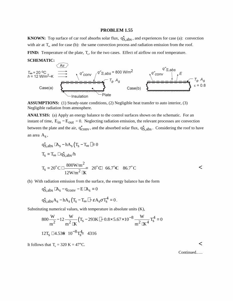
PROBLEM 1.55 KNOWN: Top surface of car roof absorbs solar flux, S,absq′′ , and experiences for case (a): convection
with air at T∞ and for case (b): the same convection process and radiation emission from the roof. FIND: Temperature of the plate, Ts, for the two cases. Effect of airflow on roof temperature. SCHEMATIC:
ASSUMPTIONS: (1) Steady-state conditions, (2) Negligible heat transfer to auto interior, (3) Negligible radiation from atmosphere. ANALYSIS: (a) Apply an energy balance to the control surfaces shown on the schematic. For an
instant of time, in outE E− = 0. Neglecting radiation emission, the relevant processes are convection
between the plate and the air, convq′′ , and the absorbed solar flux, S,absq′′ . Considering the roof to have
an area sA , ( )S,abs s s sq A hA T T 0∞′′ ⋅ − − = s S,absT T q /h∞ ′′= +
2
s 2800W/m
T 20 C 20 C 66.7 C 86.7 C12W/m K
= + = + =⋅
$ $ $ $ <
(b) With radiation emission from the surface, the energy balance has the form S,abs s conv sq A q E A 0′′ ⋅ − − ⋅ =
( ) 4S,abs s s s s sq A hA T T A T 0ε σ∞′′ − − − = .
Substituting numerical values, with temperature in absolute units (K),
( ) 8 4s s2 2 2 4
W W W800 12 T 293K 0.8 5.67 10 T 0
m m K m K
−− − − × × =⋅ ⋅
8 4s s12T 4.536 10 T 4316−+ × =
It follows that Ts = 320 K = 47°C. < Continued.….
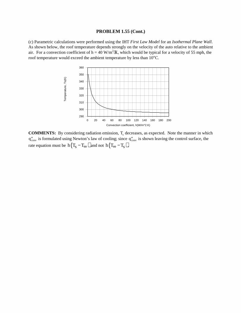
PROBLEM 1.55 (Cont.) (c) Parametric calculations were performed using the IHT First Law Model for an Isothermal Plane Wall. As shown below, the roof temperature depends strongly on the velocity of the auto relative to the ambient air. For a convection coefficient of h = 40 W/m2⋅K, which would be typical for a velocity of 55 mph, the roof temperature would exceed the ambient temperature by less than 10°C.
0 20 40 60 80 100 120 140 160 180 200
Convection coefficient, h(W/m^2.K)
290
300
310
320
330
340
350
360T
empe
ratu
re, T
s(K
)
COMMENTS: By considering radiation emission, Ts decreases, as expected. Note the manner in which
′′qconv is formulated using Newton’s law of cooling; since ′′qconv is shown leaving the control surface, the
rate equation must be ( )sh T T∞− and not ( )sh T T∞ − .
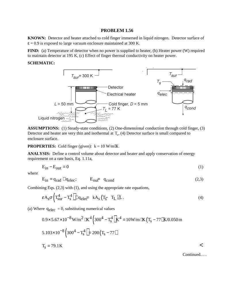
PROBLEM 1.56 KNOWN: Detector and heater attached to cold finger immersed in liquid nitrogen. Detector surface of ε = 0.9 is exposed to large vacuum enclosure maintained at 300 K. FIND: (a) Temperature of detector when no power is supplied to heater, (b) Heater power (W) required to maintain detector at 195 K, (c) Effect of finger thermal conductivity on heater power. SCHEMATIC:
ASSUMPTIONS: (1) Steady-state conditions, (2) One-dimensional conduction through cold finger, (3) Detector and heater are very thin and isothermal at Ts, (4) Detector surface is small compared to enclosure surface. PROPERTIES: Cold finger (given): k = 10 W/m⋅K. ANALYSIS: Define a control volume about detector and heater and apply conservation of energy requirement on a rate basis, Eq. 1.11a, in outE E 0− = (1)
where
in rad elec out condE q q ; E q= + = (2,3) Combining Eqs. (2,3) with (1), and using the appropriate rate equations,
( ) ( )4 4s sur s elec s s LA T T q kA T T /Lε σ − + = − . (4)
(a) Where elecq = 0, substituting numerical values
( ) ( )8 2 4 4 4 4s s0.9 5.67 10 W/m K 300 T K 10W/m K T 77 K/0.050m−× × ⋅ − = ⋅ −
( ) ( )8 4 4s s5.103 10 300 T 200 T 77−× − = −
sT 79.1K= <
Continued.….
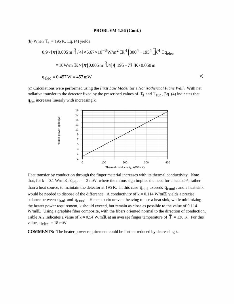
PROBLEM 1.56 (Cont.) (b) When sT = 195 K, Eq. (4) yields
( ) ( )2 8 2 4 4 4 4elec0.9 [ 0.005m / 4] 5.67 10 W/m K 300 195 K qπ −× × × ⋅ − +
( ) ( )210W/m K [ 0.005m /4] 195 77 K / 0.050mπ= ⋅ × × −
elecq 0.457 W 457 mW= = <
(c) Calculations were performed using the First Law Model for a Nonisothermal Plane Wall. With net radiative transfer to the detector fixed by the prescribed values of sT and surT , Eq. (4) indicates that
qelec increases linearly with increasing k.
0 100 200 300 400
Thermal conductivity, k(W/m.K)
-1
1
3
5
7
9
11
13
15
17
19
Hea
ter
pow
er, q
elec
(W)
Heat transfer by conduction through the finger material increases with its thermal conductivity. Note that, for k = 0.1 W/m⋅K, elecq = -2 mW, where the minus sign implies the need for a heat sink, rather
than a heat source, to maintain the detector at 195 K. In this case radq exceeds condq , and a heat sink
would be needed to dispose of the difference. A conductivity of k = 0.114 W/m⋅K yields a precise balance between radq and condq . Hence to circumvent heaving to use a heat sink, while minimizing
the heater power requirement, k should exceed, but remain as close as possible to the value of 0.114 W/m⋅K. Using a graphite fiber composite, with the fibers oriented normal to the direction of conduction,
Table A.2 indicates a value of k ≈ 0.54 W/m⋅K at an average finger temperature of T = 136 K. For this value, elecq = 18 mW COMMENTS: The heater power requirement could be further reduced by decreasing ε.
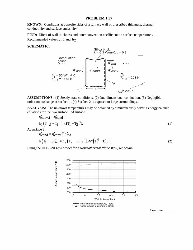
PROBLEM 1.57
KNOWN: Conditions at opposite sides of a furnace wall of prescribed thickness, thermal conductivity and surface emissivity. FIND: Effect of wall thickness and outer convection coefficient on surface temperatures. Recommended values of L and 2h . SCHEMATIC:
ASSUMPTIONS: (1) Steady-state conditions, (2) One-dimensional conduction, (3) Negligible radiation exchange at surface 1, (4) Surface 2 is exposed to large surroundings. ANALYSIS: The unknown temperatures may be obtained by simultaneously solving energy balance equations for the two surface. At surface 1, conv,1 condq q′′ ′′=
( ) ( )1 ,1 1 1 2h T T k T T /L∞ − = − (1)
At surface 2, cond conv radq q q′′ ′′ ′′= +
( ) ( ) ( )4 41 2 2 2 ,2 sur2k T T /L h T T T Tεσ∞− = − + − (2)
Using the IHT First Law Model for a Nonisothermal Plane Wall, we obtain
0 0.1 0.2 0.3 0.4 0.5
Wall thickness, L(m)
300
500
700
900
1100
1300
1500
1700
Sur
face
tem
pera
ture
, T(K
)
Inner surface temperature, T1(K)Outer surface temperature, T2(K)
Continued …..
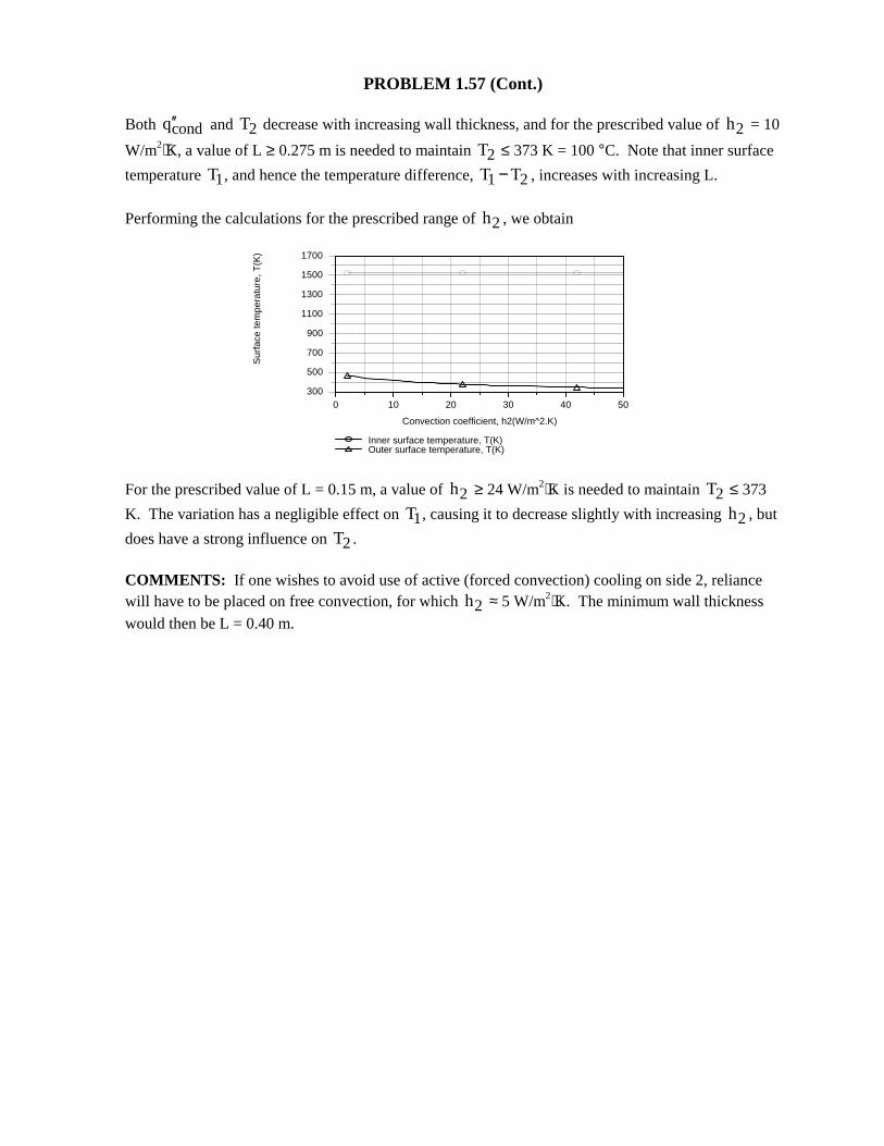
PROBLEM 1.57 (Cont.)
Both condq′′ and 2T decrease with increasing wall thickness, and for the prescribed value of 2h = 10
W/m2⋅K, a value of L ≥ 0.275 m is needed to maintain 2T ≤ 373 K = 100 °C. Note that inner surface
temperature 1T , and hence the temperature difference, 1 2T T− , increases with increasing L. Performing the calculations for the prescribed range of 2h , we obtain
0 10 20 30 40 50
Convection coefficient, h2(W/m^2.K)
300
500
700
900
1100
1300
1500
1700S
urfa
ce te
mpe
ratu
re, T
(K)
Inner surface temperature, T(K)Outer surface temperature, T(K)
For the prescribed value of L = 0.15 m, a value of 2h ≥ 24 W/m2⋅K is needed to maintain 2T ≤ 373
K. The variation has a negligible effect on 1T , causing it to decrease slightly with increasing 2h , but
does have a strong influence on 2T . COMMENTS: If one wishes to avoid use of active (forced convection) cooling on side 2, reliance will have to be placed on free convection, for which 2h ≈ 5 W/m2⋅K. The minimum wall thickness would then be L = 0.40 m.
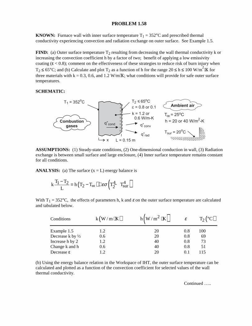
PROBLEM 1.58 KNOWN: Furnace wall with inner surface temperature T1 = 352°C and prescribed thermal conductivity experiencing convection and radiation exchange on outer surface. See Example 1.5.
FIND: (a) Outer surface temperature T2 resulting from decreasing the wall thermal conductivity k or increasing the convection coefficient h by a factor of two; benefit of applying a low emissivity coating (ε < 0.8); comment on the effectiveness of these strategies to reduce risk of burn injury when T2 ≤ 65°C; and (b) Calculate and plot T2 as a function of h for the range 20 ≤ h ≤ 100 W/m
2⋅K for three materials with k = 0.3, 0.6, and 1.2 W/m⋅K; what conditions will provide for safe outer surface temperatures. SCHEMATIC:
ASSUMPTIONS: (1) Steady-state conditions, (2) One-dimensional conduction in wall, (3) Radiation exchange is between small surface and large enclosure, (4) Inner surface temperature remains constant for all conditions. ANALYSIS: (a) The surface (x = L) energy balance is
( ) ( )4 41 22 sur2
T Tk h T T T T
Lεσ∞
− = − + −
With T1 = 352°C, the effects of parameters h, k and ε on the outer surface temperature are calculated and tabulated below.
Conditions ( )k W / m K⋅ ( )2h W / m K⋅ ε ( )2T C°
Example 1.5 1.2 20 0.8 100 Decrease k by ½ 0.6 20 0.8 69 Increase h by 2 1.2 40 0.8 73 Change k and h 0.6 40 0.8 51 Decrease ε 1.2 20 0.1 115 (b) Using the energy balance relation in the Workspace of IHT, the outer surface temperature can be calculated and plotted as a function of the convection coefficient for selected values of the wall thermal conductivity. Continued …..
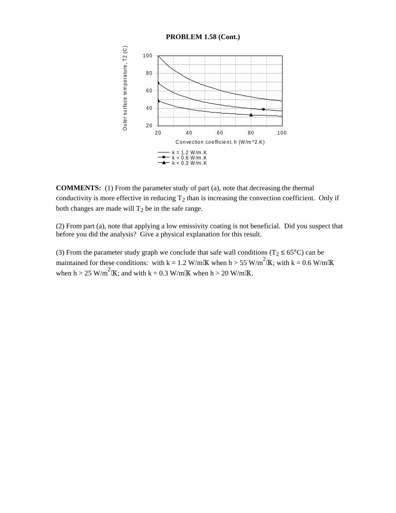
PROBLEM 1.58 (Cont.) COMMENTS: (1) From the parameter study of part (a), note that decreasing the thermal
conductivity is more effective in reducing T2 than is increasing the convection coefficient. Only if
both changes are made will T2 be in the safe range. (2) From part (a), note that applying a low emissivity coating is not beneficial. Did you suspect that before you did the analysis? Give a physical explanation for this result. (3) From the parameter study graph we conclude that safe wall conditions (T2 ≤ 65°C) can be
maintained for these conditions: with k = 1.2 W/m⋅K when h > 55 W/m2⋅K; with k = 0.6 W/m⋅K
when h > 25 W/m2⋅K; and with k = 0.3 W/m⋅K when h > 20 W/m⋅K.
2 0 4 0 6 0 8 0 1 0 0
C o n ve ctio n co e fficie n t, h (W /m ^2 .K )
2 0
4 0
6 0
8 0
1 0 0
Ou
ter
surf
ace
tem
pe
ratu
re, T
2 (
C)
k = 1 .2 W /m .Kk = 0 .6 W /m .Kk = 0 .3 W /m .K
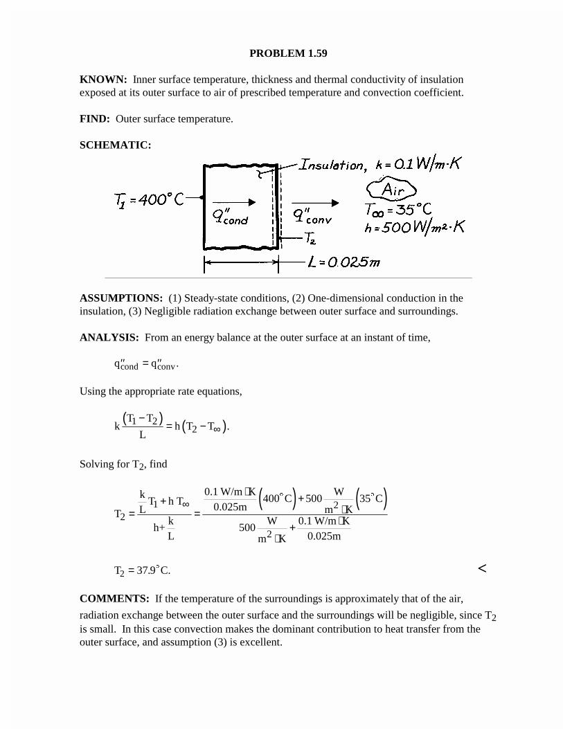
PROBLEM 1.59
KNOWN: Inner surface temperature, thickness and thermal conductivity of insulationexposed at its outer surface to air of prescribed temperature and convection coefficient.
FIND: Outer surface temperature.
SCHEMATIC:
ASSUMPTIONS: (1) Steady-state conditions, (2) One-dimensional conduction in theinsulation, (3) Negligible radiation exchange between outer surface and surroundings.
ANALYSIS: From an energy balance at the outer surface at an instant of time,
′′ = ′′q qcond conv.
Using the appropriate rate equations,
( ) ( )1 22
T Tk h T T .
L ∞−
= −
Solving for T2, find
( ) ( )1 22
2
0.1 W/m K Wk 400 C 500 35 CT h T 0.025mL m KTk W 0.1 W/m K
h+ 500L 0.025mm K
∞⋅ ++
⋅= = ⋅+⋅
$ $
T C.2 = 37 9. $ <
COMMENTS: If the temperature of the surroundings is approximately that of the air,
radiation exchange between the outer surface and the surroundings will be negligible, since T2is small. In this case convection makes the dominant contribution to heat transfer from theouter surface, and assumption (3) is excellent.
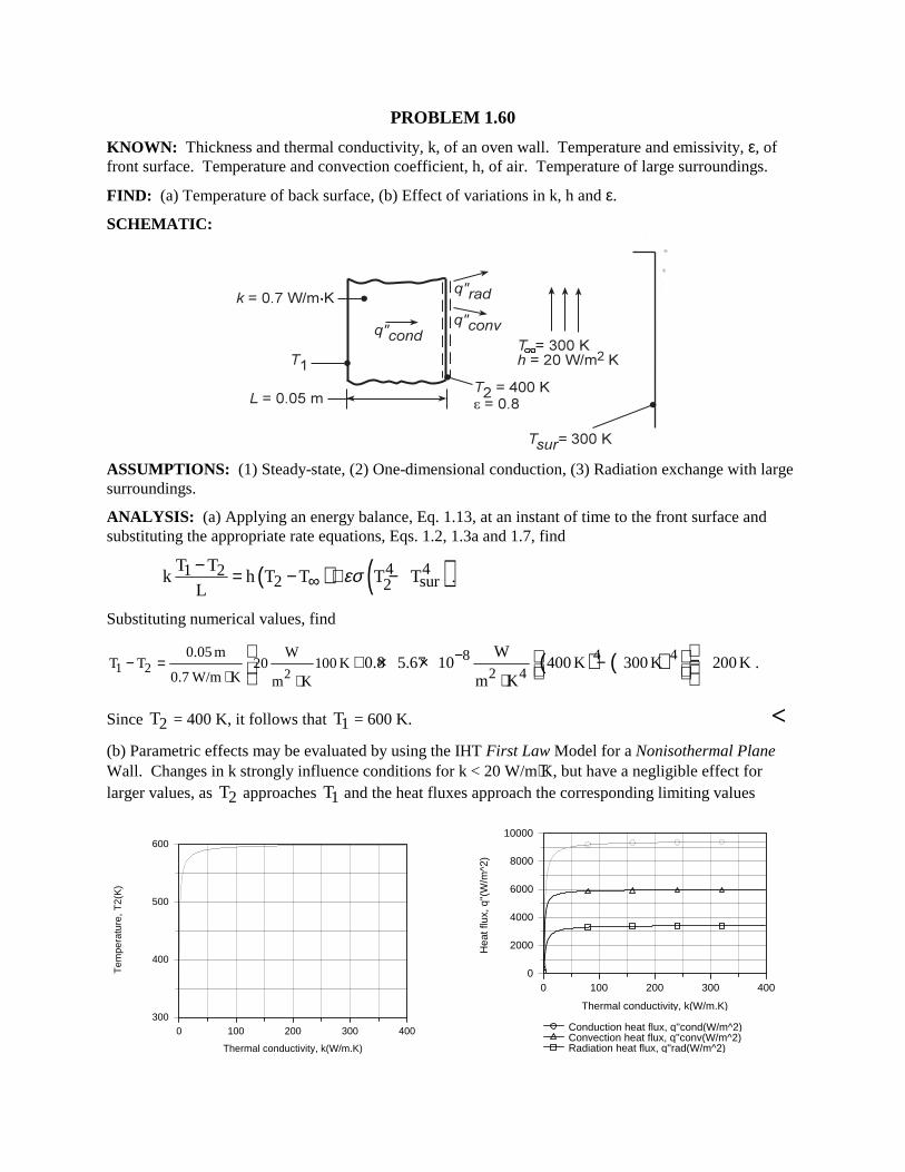
PROBLEM 1.60 KNOWN: Thickness and thermal conductivity, k, of an oven wall. Temperature and emissivity, ε, of front surface. Temperature and convection coefficient, h, of air. Temperature of large surroundings. FIND: (a) Temperature of back surface, (b) Effect of variations in k, h and ε. SCHEMATIC:
ASSUMPTIONS: (1) Steady-state, (2) One-dimensional conduction, (3) Radiation exchange with large surroundings. ANALYSIS: (a) Applying an energy balance, Eq. 1.13, at an instant of time to the front surface and substituting the appropriate rate equations, Eqs. 1.2, 1.3a and 1.7, find
( ) ( )4 41 22 sur2
T Tk h T T T T
Lεσ∞
− = − + − .
Substituting numerical values, find
( ) ( )1 2 2
0.05 m W 4 48T T 20 100 K2 40.7 W/m K m K
W0.8 5.67 10 400 K 300 K 200 K
m K
−− =⋅ ⋅
+ × × − =⋅
.
Since 2T = 400 K, it follows that 1T = 600 K. < (b) Parametric effects may be evaluated by using the IHT First Law Model for a Nonisothermal Plane Wall. Changes in k strongly influence conditions for k < 20 W/m⋅K, but have a negligible effect for larger values, as 2T approaches 1T and the heat fluxes approach the corresponding limiting values
0 100 200 300 400
Thermal conductivity, k(W/m.K)
300
400
500
600
Tem
pera
ture
, T2(
K)
0 100 200 300 400
Thermal conductivity, k(W/m.K)
0
2000
4000
6000
8000
10000
Hea
t flu
x, q
''(W
/m^2
)
Conduction heat flux, q''cond(W/m^2)Convection heat flux, q''conv(W/m^2)Radiation heat flux, q''rad(W/m^2)
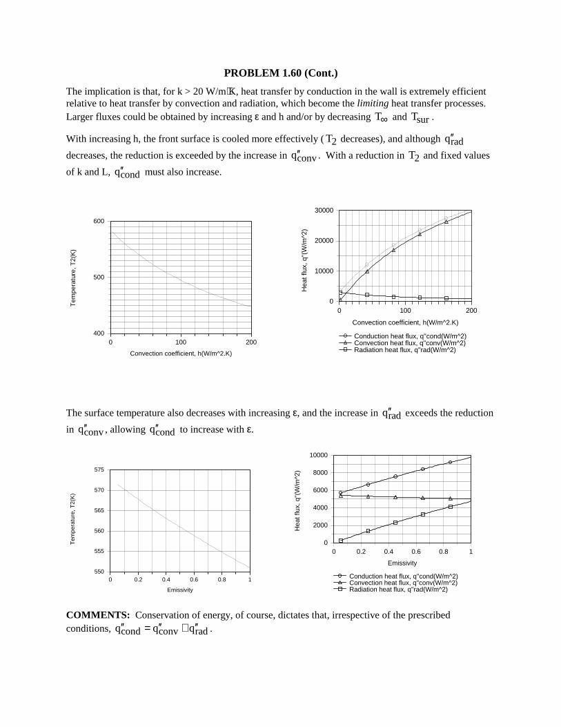
PROBLEM 1.60 (Cont.) The implication is that, for k > 20 W/m⋅K, heat transfer by conduction in the wall is extremely efficient relative to heat transfer by convection and radiation, which become the limiting heat transfer processes. Larger fluxes could be obtained by increasing ε and h and/or by decreasing T∞ and surT . With increasing h, the front surface is cooled more effectively (2T decreases), and although radq′′
decreases, the reduction is exceeded by the increase in convq′′ . With a reduction in 2T and fixed values
of k and L, condq′′ must also increase.
0 100 200
Convection coefficient, h(W/m^2.K)
400
500
600
Tem
pera
ture
, T2(
K)
0 100 200
Convection coefficient, h(W/m^2.K)
0
10000
20000
30000
Hea
t flu
x, q
''(W
/m^2
)
Conduction heat flux, q''cond(W/m^2)Convection heat flux, q''conv(W/m^2)Radiation heat flux, q''rad(W/m^2)
The surface temperature also decreases with increasing ε, and the increase in radq′′ exceeds the reduction
in convq′′ , allowing condq′′ to increase with ε.
0 0.2 0.4 0.6 0.8 1
Emissivity
550
555
560
565
570
575
Tem
pera
ture
, T2(
K)
0 0.2 0.4 0.6 0.8 1
Emissivity
0
2000
4000
6000
8000
10000
Hea
t flu
x, q
''(W
/m^2
)
Conduction heat flux, q''cond(W/m^2)Convection heat flux, q''conv(W/m^2)Radiation heat flux, q''rad(W/m^2)
COMMENTS: Conservation of energy, of course, dictates that, irrespective of the prescribed conditions, cond conv radq q q′′ ′′ ′′= + .
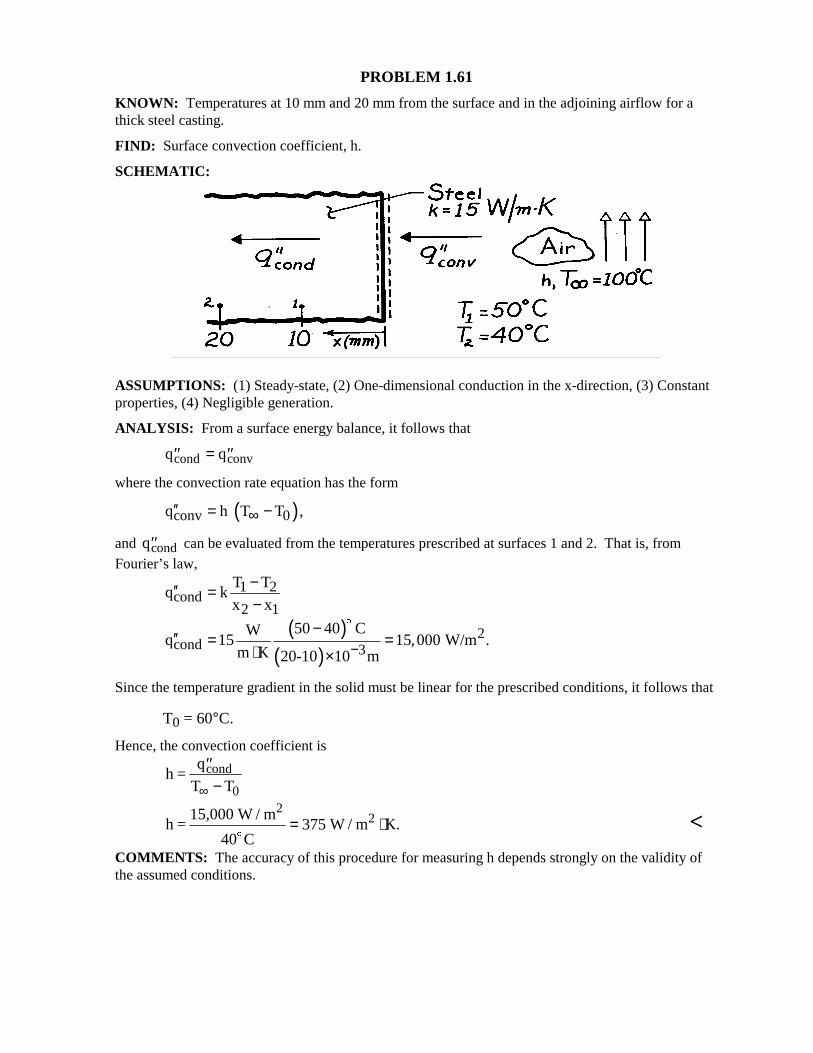
PROBLEM 1.61
KNOWN: Temperatures at 10 mm and 20 mm from the surface and in the adjoining airflow for athick steel casting.
FIND: Surface convection coefficient, h.
SCHEMATIC:
ASSUMPTIONS: (1) Steady-state, (2) One-dimensional conduction in the x-direction, (3) Constantproperties, (4) Negligible generation.
ANALYSIS: From a surface energy balance, it follows that
′′ = ′′q qcond conv
where the convection rate equation has the form
( )conv 0q h T T ,∞′′ = −
and ′′qcond can be evaluated from the temperatures prescribed at surfaces 1 and 2. That is, fromFourier’s law,
( )( )
1 2cond
2 1
2cond 3
T Tq k
x x
50 40 CWq 15 15,000 W/m .
m K 20-10 10 m−
−′′ =−
−′′ = =
⋅ ×
$
Since the temperature gradient in the solid must be linear for the prescribed conditions, it follows that
T0 = 60°C.
Hence, the convection coefficient is
h =q
T Tcond
0
′′−∞
h =15,000 W / m
40 C W / m K.
22
$
= ⋅375 <COMMENTS: The accuracy of this procedure for measuring h depends strongly on the validity ofthe assumed conditions.
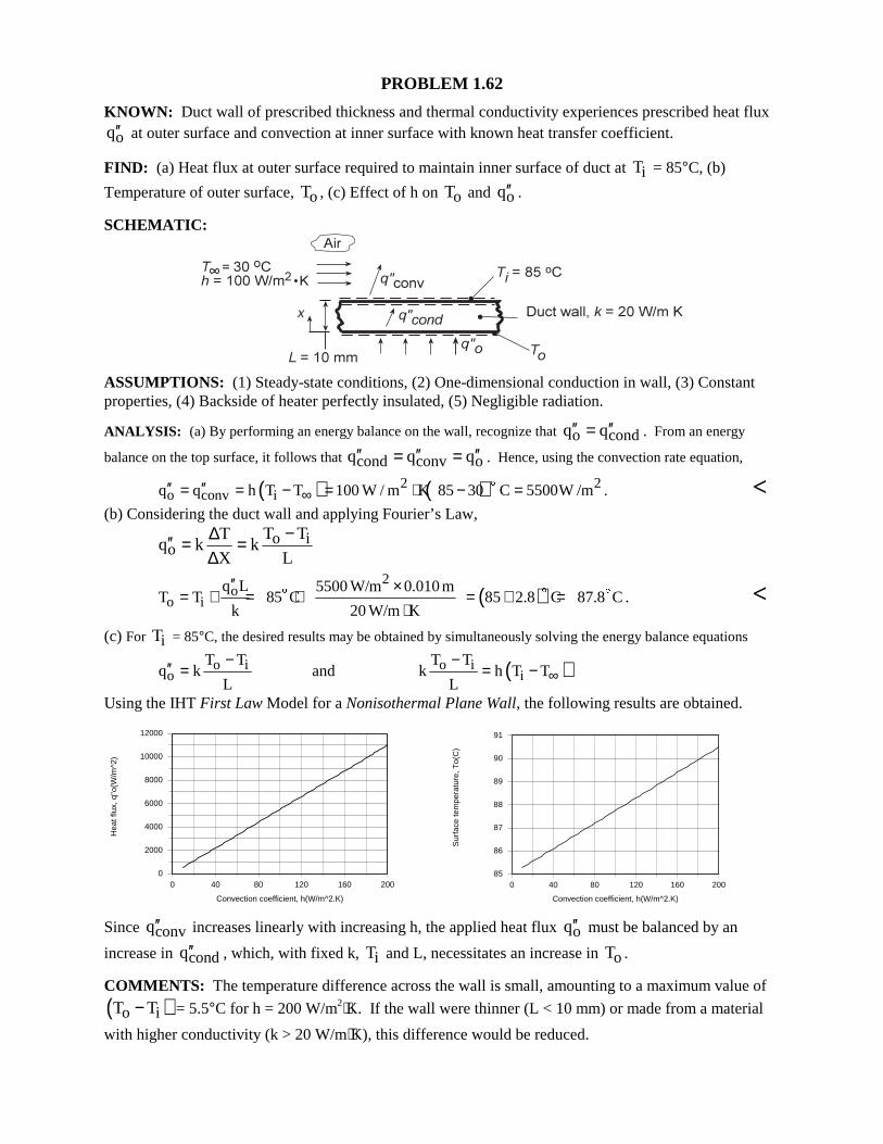
PROBLEM 1.62 KNOWN: Duct wall of prescribed thickness and thermal conductivity experiences prescribed heat flux
oq′′ at outer surface and convection at inner surface with known heat transfer coefficient. FIND: (a) Heat flux at outer surface required to maintain inner surface of duct at iT = 85°C, (b)
Temperature of outer surface, oT , (c) Effect of h on oT and oq′′ . SCHEMATIC:
ASSUMPTIONS: (1) Steady-state conditions, (2) One-dimensional conduction in wall, (3) Constant properties, (4) Backside of heater perfectly insulated, (5) Negligible radiation. ANALYSIS: (a) By performing an energy balance on the wall, recognize that o condq q′′ ′′= . From an energy
balance on the top surface, it follows that cond conv oq q q′′ ′′ ′′= = . Hence, using the convection rate equation,
( ) ( )2 2o conv iq q h T T 100 W / m K 85 30 C 5500W /m∞′′ ′′= = − = ⋅ − =$ . <
(b) Considering the duct wall and applying Fourier’s Law,
o io
T TTq k k
X L
−∆′′ = =∆
2
oo i
q L 5500 W/m 0.010 mT T 85 C
k 20 W/m K
′′ ×= + = +
⋅$ ( )85 2.8 C 87.8 C= + =$ $ . <
(c) For iT = 85°C, the desired results may be obtained by simultaneously solving the energy balance equations
o io
T Tq k
L
−′′ = and ( )o ii
T Tk h T T
L∞
−= −
Using the IHT First Law Model for a Nonisothermal Plane Wall, the following results are obtained.
0 40 80 120 160 200
Convection coefficient, h(W/m^2.K)
0
2000
4000
6000
8000
10000
12000
Hea
t flu
x, q
''o(W
/m^2
)
0 40 80 120 160 200
Convection coefficient, h(W/m^2.K)
85
86
87
88
89
90
91
Sur
face
tem
pera
ture
, To(
C)
Since convq′′ increases linearly with increasing h, the applied heat flux oq′′ must be balanced by an
increase in condq′′ , which, with fixed k, iT and L, necessitates an increase in oT . COMMENTS: The temperature difference across the wall is small, amounting to a maximum value of
( )o iT T− = 5.5°C for h = 200 W/m2⋅K. If the wall were thinner (L < 10 mm) or made from a material
with higher conductivity (k > 20 W/m⋅K), this difference would be reduced.
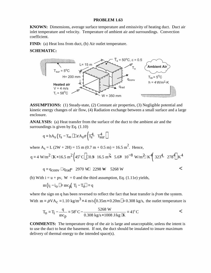
PROBLEM 1.63 KNOWN: Dimensions, average surface temperature and emissivity of heating duct. Duct air inlet temperature and velocity. Temperature of ambient air and surroundings. Convection coefficient. FIND: (a) Heat loss from duct, (b) Air outlet temperature. SCHEMATIC:
ASSUMPTIONS: (1) Steady-state, (2) Constant air properties, (3) Negligible potential and kinetic energy changes of air flow, (4) Radiation exchange between a small surface and a large enclosure. ANALYSIS: (a) Heat transfer from the surface of the duct to the ambient air and the surroundings is given by Eq. (1.10)
( ) ( )4 4q hA T T A T Ts s s s surε σ= − + −∞
where As = L (2W + 2H) = 15 m (0.7 m + 0.5 m) = 16.5 m
2. Hence,
( ) ( )2 2 2 8 2 4 4 4 4q 4 W/m K 16.5 m 45 C 0.5 16.5 m 5.67 10 W/m K 323 278 K−= ⋅ × + × × × ⋅ −$
q q q 2970 W 2298 W 5268 Wconv rad= + = + = < (b) With i = u + pv, W = 0 and the third assumption, Eq. (1.11e) yields, ( ) ( )m i i mc T T qi o p i o− = − = where the sign on q has been reversed to reflect the fact that heat transfer is from the system.
With ( )3m VA 1.10 kg/m 4 m/s 0.35m 0.20m 0.308 kg/s,cρ= = × × = the outlet temperature is
q 5268 W
T T 58 C 41 Co i mc 0.308 kg/s 1008 J/kg Kp= − = − =
× ⋅$ $
<
COMMENTS: The temperature drop of the air is large and unacceptable, unless the intent is to use the duct to heat the basement. If not, the duct should be insulated to insure maximum delivery of thermal energy to the intended space(s).
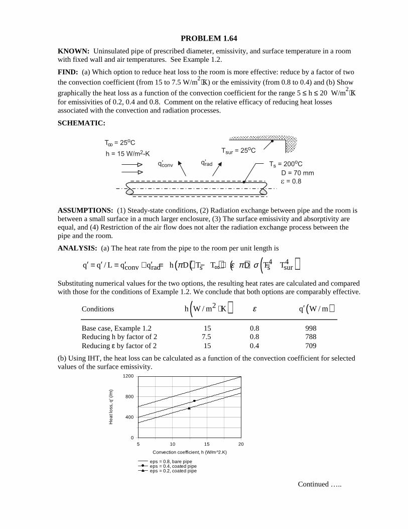
PROBLEM 1.64 KNOWN: Uninsulated pipe of prescribed diameter, emissivity, and surface temperature in a room with fixed wall and air temperatures. See Example 1.2. FIND: (a) Which option to reduce heat loss to the room is more effective: reduce by a factor of two the convection coefficient (from 15 to 7.5 W/m
2⋅K) or the emissivity (from 0.8 to 0.4) and (b) Show
graphically the heat loss as a function of the convection coefficient for the range 5 ≤ h ≤ 20 W/m2⋅K
for emissivities of 0.2, 0.4 and 0.8. Comment on the relative efficacy of reducing heat losses associated with the convection and radiation processes. SCHEMATIC:
ASSUMPTIONS: (1) Steady-state conditions, (2) Radiation exchange between pipe and the room is between a small surface in a much larger enclosure, (3) The surface emissivity and absorptivity are equal, and (4) Restriction of the air flow does not alter the radiation exchange process between the pipe and the room. ANALYSIS: (a) The heat rate from the pipe to the room per unit length is
( )( ) ( ) ( )4 4conv rad s s surq q / L q q h D T T D T Tπ ε π σ∞′ ′ ′ ′= = + = − + −
Substituting numerical values for the two options, the resulting heat rates are calculated and compared with those for the conditions of Example 1.2. We conclude that both options are comparably effective.
Conditions ( )2h W / m K⋅ ε ( )q W / m′
Base case, Example 1.2 15 0.8 998 Reducing h by factor of 2 7.5 0.8 788 Reducing ε by factor of 2 15 0.4 709 (b) Using IHT, the heat loss can be calculated as a function of the convection coefficient for selected values of the surface emissivity. Continued …..
5 10 15 20
Convection coefficient, h (W/m^2.K)
0
400
800
1200
He
at l
oss
, q' (
/m)
eps = 0.8, bare pipeeps = 0.4, coated pipeeps = 0.2, coated pipe
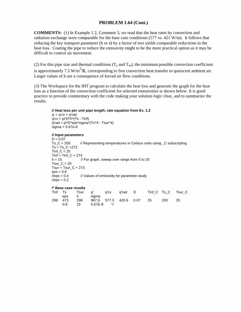
PROBLEM 1.64 (Cont.) COMMENTS: (1) In Example 1.2, Comment 3, we read that the heat rates by convection and radiation exchange were comparable for the base case conditions (577 vs. 421 W/m). It follows that reducing the key transport parameter (h or ε) by a factor of two yields comparable reductions in the heat loss. Coating the pipe to reduce the emissivity might to be the more practical option as it may be difficult to control air movement.
(2) For this pipe size and thermal conditions (Ts and T∞), the minimum possible convection coefficient
is approximately 7.5 W/m2⋅K, corresponding to free convection heat transfer to quiescent ambient air.
Larger values of h are a consequence of forced air flow conditions. (3) The Workspace for the IHT program to calculate the heat loss and generate the graph for the heat loss as a function of the convection coefficient for selected emissivities is shown below. It is good practice to provide commentary with the code making your solution logic clear, and to summarize the results.
// Heat loss per unit pipe length; rate equation from Ex. 1.2 q' = q'cv + q'rad q'cv = pi*D*h*(Ts - Tinf) q'rad = pi*D*eps*sigma*(Ts^4 - Tsur^4) sigma = 5.67e-8 // Input parameters D = 0.07 Ts_C = 200 // Representing temperatures in Celsius units using _C subscripting Ts = Ts_C +273 Tinf_C = 25 Tinf = Tinf_C + 273 h = 15 // For graph, sweep over range from 5 to 20 Tsur_C = 25 Tsur = Tsur_C + 273 eps = 0.8 //eps = 0.4 // Values of emissivity for parameter study //eps = 0.2 /* Base case results Tinf Ts Tsur q' q'cv q'rad D Tinf_C Ts_C Tsur_C eps h sigma 298 473 298 997.9 577.3 420.6 0.07 25 200 25 0.8 15 5.67E-8 */
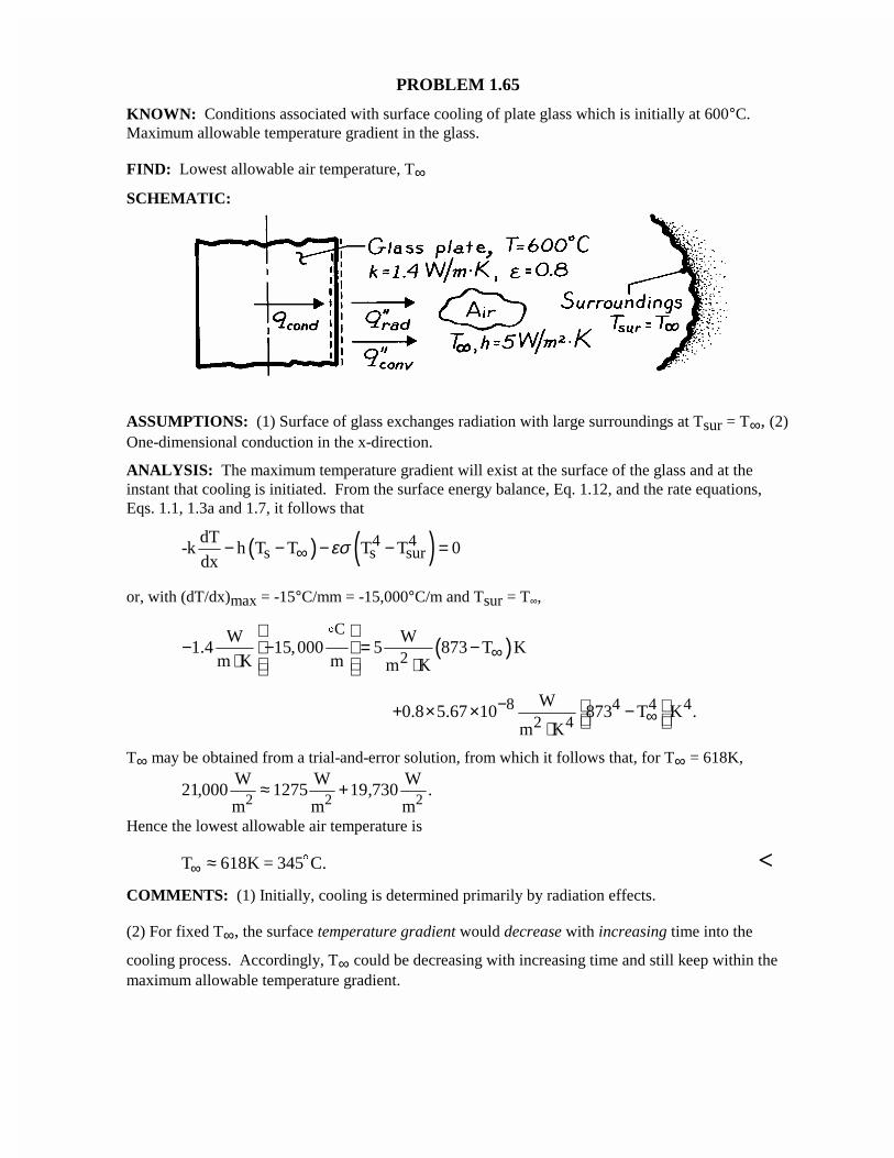
PROBLEM 1.65
KNOWN: Conditions associated with surface cooling of plate glass which is initially at 600°C.Maximum allowable temperature gradient in the glass.
FIND: Lowest allowable air temperature, T∞
SCHEMATIC:
ASSUMPTIONS: (1) Surface of glass exchanges radiation with large surroundings at Tsur = T∞, (2)One-dimensional conduction in the x-direction.
ANALYSIS: The maximum temperature gradient will exist at the surface of the glass and at theinstant that cooling is initiated. From the surface energy balance, Eq. 1.12, and the rate equations,Eqs. 1.1, 1.3a and 1.7, it follows that
( ) ( )4 4s s sur
dT-k h T T T T 0
dxεσ∞− − − − =
or, with (dT/dx)max = -15°C/mm = -15,000°C/m and Tsur = T∞,
( )C
2W W
1.4 15,000 5 873 T Km K m m K
∞
− − = − ⋅ ⋅
$
8 4 4 42 4W
0.8 5.67 10 873 T K .m K
−∞ + × × − ⋅
T∞ may be obtained from a trial-and-error solution, from which it follows that, for T∞ = 618K,
21 000 1275 19 730, , .W
m
W
m
W
m2 2 2≈ +
Hence the lowest allowable air temperature is
T K = 345 C.∞ ≈ 618 $ <COMMENTS: (1) Initially, cooling is determined primarily by radiation effects.
(2) For fixed T∞, the surface temperature gradient would decrease with increasing time into the
cooling process. Accordingly, T∞ could be decreasing with increasing time and still keep within themaximum allowable temperature gradient.
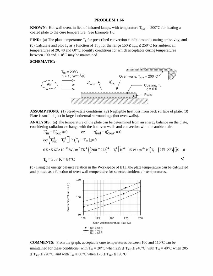
PROBLEM 1.66 KNOWN: Hot-wall oven, in lieu of infrared lamps, with temperature Tsur = 200°C for heating a coated plate to the cure temperature. See Example 1.6. FIND: (a) The plate temperature Ts for prescribed convection conditions and coating emissivity, and
(b) Calculate and plot Ts as a function of Tsur for the range 150 ≤ Tsur ≤ 250°C for ambient air temperatures of 20, 40 and 60°C; identify conditions for which acceptable curing temperatures between 100 and 110°C may be maintained. SCHEMATIC:
ASSUMPTIONS: (1) Steady-state conditions, (2) Negligible heat loss from back surface of plate, (3) Plate is small object in large isothermal surroundings (hot oven walls). ANALYSIS: (a) The temperature of the plate can be determined from an energy balance on the plate, considering radiation exchange with the hot oven walls and convection with the ambient air.
in out rad convE E 0 or q q 0′′ ′′ ′′ ′′− = − =
( ) ( )4 4sur s sT T h T T 0εσ ∞− − − =
[ ]( ) [ ]( )48 2 4 4 4 2s s0.5 5.67 10 W / m K 200 273 T K 15 W / m K T 20 273 K 0−× × ⋅ + − − ⋅ − + =
sT 357 K 84 C= = ° < (b) Using the energy balance relation in the Workspace of IHT, the plate temperature can be calculated and plotted as a function of oven wall temperature for selected ambient air temperatures. COMMENTS: From the graph, acceptable cure temperatures between 100 and 110°C can be
maintained for these conditions: with T∞ = 20°C when 225 ≤ Tsur ≤ 240°C; with T∞ = 40°C when 205
≤ Tsur ≤ 220°C; and with T∞ = 60°C when 175 ≤ Tsur ≤ 195°C.
150 175 200 225 250
Oven wall temperature, Tsur (C)
50
100
150
Pla
te te
mpe
ratu
re, T
s (C
)
Tinf = 60 CTinf = 40 CTinf = 20 C
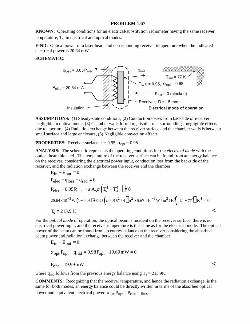
PROBLEM 1.67 KNOWN: Operating conditions for an electrical-substitution radiometer having the same receiver temperature, Ts, in electrical and optical modes. FIND: Optical power of a laser beam and corresponding receiver temperature when the indicated electrical power is 20.64 mW. SCHEMATIC:
ASSUMPTIONS: (1) Steady-state conditions, (2) Conduction losses from backside of receiver negligible in optical mode, (3) Chamber walls form large isothermal surroundings; negligible effects due to aperture, (4) Radiation exchange between the receiver surface and the chamber walls is between small surface and large enclosure, (5) Negligible convection effects. PROPERTIES: Receiver surface: ε = 0.95, αopt = 0.98. ANALYSIS: The schematic represents the operating conditions for the electrical mode with the optical beam blocked. The temperature of the receiver surface can be found from an energy balance on the receiver, considering the electrical power input, conduction loss from the backside of the receiver, and the radiation exchange between the receiver and the chamber.
in outE E 0− =
elec loss radP q q 0− − =
( )4 4elec elec s s surP 0.05P A T T 0ε σ− − − =
( ) ( ) ( )3 2 8 2 4 4 4 4s
220.64 10 W 1 0.05 0.95 0.015 / 4 5.67 10 W / m K T 77 Km 0π− −× − − × × ⋅ − =
sT 213.9 K= < For the optical mode of operation, the optical beam is incident on the receiver surface, there is no electrical power input, and the receiver temperature is the same as for the electrical mode. The optical power of the beam can be found from an energy balance on the receiver considering the absorbed beam power and radiation exchange between the receiver and the chamber.
in outE E 0− = opt opt rad optP q 0.98P 19.60mW 0α − = − =
optP 19.99mW= <
where qrad follows from the previous energy balance using Ts = 213.9K. COMMENTS: Recognizing that the receiver temperature, and hence the radiation exchange, is the same for both modes, an energy balance could be directly written in terms of the absorbed optical power and equivalent electrical power, αopt Popt = Pelec - qloss.
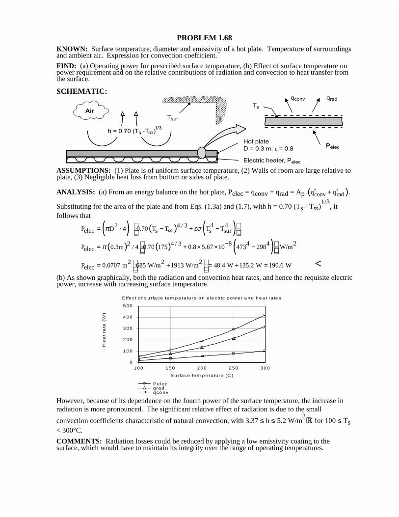
PROBLEM 1.68KNOWN: Surface temperature, diameter and emissivity of a hot plate. Temperature of surroundingsand ambient air. Expression for convection coefficient.
FIND: (a) Operating power for prescribed surface temperature, (b) Effect of surface temperature onpower requirement and on the relative contributions of radiation and convection to heat transfer fromthe surface.
SCHEMATIC:
ASSUMPTIONS: (1) Plate is of uniform surface temperature, (2) Walls of room are large relative toplate, (3) Negligible heat loss from bottom or sides of plate.
ANALYSIS: (a) From an energy balance on the hot plate, Pelec = qconv + qrad = Ap ( )conv radq q .′′ ′′+
Substituting for the area of the plate and from Eqs. (1.3a) and (1.7), with h = 0.70 (Ts - T∞)1/3
, itfollows that
( ) ( ) ( )2 4 44 / 3P D / 4 0.70 T T T Telec s s surπ εσ= − + −∞
( ) ( ) ( )8 4 4 22 4 / 3P 0.3m / 4 0.70 175 0.8 5.67 10 473 298 W/melec π −= + × × −
2 2 2P 0.0707 m 685 W/m 1913 W/m 48.4 W 135.2 W 190.6 Welec = + = + = <
(b) As shown graphically, both the radiation and convection heat rates, and hence the requisite electricpower, increase with increasing surface temperature.
However, because of its dependence on the fourth power of the surface temperature, the increase inradiation is more pronounced. The significant relative effect of radiation is due to the small
convection coefficients characteristic of natural convection, with 3.37 ≤ h ≤ 5.2 W/m2⋅K for 100 ≤ Ts
< 300°C.
COMMENTS: Radiation losses could be reduced by applying a low emissivity coating to thesurface, which would have to maintain its integrity over the range of operating temperatures.
Effe ct o f s u rfa ce te m p era tu re o n e lectric p ow e r a n d he a t ra te s
1 00 1 50 2 00 2 50 3 00
Surfa ce tem p era tu re (C )
0
1 00
2 00
3 00
4 00
5 00
He
at
rate
(W
)
P e lecq radq co nv
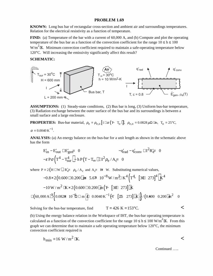
PROBLEM 1.69 KNOWN: Long bus bar of rectangular cross-section and ambient air and surroundings temperatures. Relation for the electrical resistivity as a function of temperature. FIND: (a) Temperature of the bar with a current of 60,000 A, and (b) Compute and plot the operating temperature of the bus bar as a function of the convection coefficient for the range 10 ≤ h ≤ 100
W/m2⋅K. Minimum convection coefficient required to maintain a safe-operating temperature below
120°C. Will increasing the emissivity significantly affect this result? SCHEMATIC:
ASSUMPTIONS: (1) Steady-state conditions, (2) Bus bar is long, (3) Uniform bus-bar temperature, (3) Radiation exchange between the outer surface of the bus bar and its surroundings is between a small surface and a large enclosure. PROPERTIES: Bus-bar material, ( )[ ]e e,o o1 T T ,ρ ρ α= + − e,o 0.0828 m,ρ µ= Ω ⋅ oT 25 C,= °
10.0040 K .α −= ANALYSIS: (a) An energy balance on the bus-bar for a unit length as shown in the schematic above has the form
in out genE E E 0′ ′ ′− + = 2rad conv eq q I R 0′ ′ ′− − + =
( ) ( )4 4 2sur e cP T T h P T T I / A 0ε σ ρ∞− − − − + =
where ( ) e e c cP 2 H W , R / A and A H W.ρ′= + = = × Substituting numerical values,
( ) [ ]( )48 2 4 4 40.8 2 0.600 0.200 m 5.67 10 W / m K T 30 273 K−− × + × × ⋅ − +
( ) [ ]( )210 W / m K 2 0.600 0.200 m T 30 273 K− ⋅ × + − +
( ) [ ]( ) ( )2 6 1 260,000 A 0.0828 10 m 1 0.0040 K T 25 273 K / 0.600 0.200 m 0− −+ × Ω ⋅ + − + × =
Solving for the bus-bar temperature, find T 426 K 153 C.= = ° < (b) Using the energy balance relation in the Workspace of IHT, the bus-bar operating temperature is calculated as a function of the convection coefficient for the range 10 ≤ h ≤ 100 W/m
2⋅K. From this graph we can determine that to maintain a safe operating temperature below 120°C, the minimum convection coefficient required is
2minh 16 W / m K.= ⋅ <
Continued …..
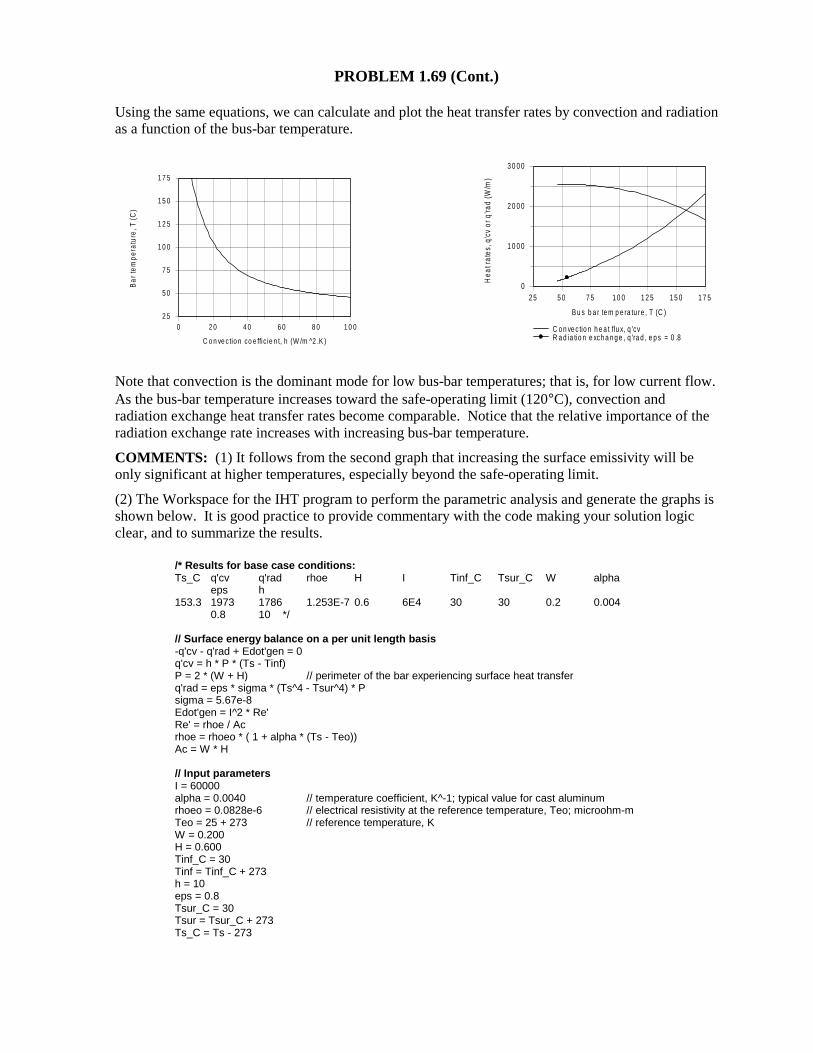
PROBLEM 1.69 (Cont.) Using the same equations, we can calculate and plot the heat transfer rates by convection and radiation as a function of the bus-bar temperature.
Note that convection is the dominant mode for low bus-bar temperatures; that is, for low current flow. As the bus-bar temperature increases toward the safe-operating limit (120°C), convection and radiation exchange heat transfer rates become comparable. Notice that the relative importance of the radiation exchange rate increases with increasing bus-bar temperature. COMMENTS: (1) It follows from the second graph that increasing the surface emissivity will be only significant at higher temperatures, especially beyond the safe-operating limit. (2) The Workspace for the IHT program to perform the parametric analysis and generate the graphs is shown below. It is good practice to provide commentary with the code making your solution logic clear, and to summarize the results.
/* Results for base case conditions: Ts_C q'cv q'rad rhoe H I Tinf_C Tsur_C W alpha eps h 153.3 1973 1786 1.253E-7 0.6 6E4 30 30 0.2 0.004 0.8 10 */ // Surface energy balance on a per unit length basis -q'cv - q'rad + Edot'gen = 0 q'cv = h * P * (Ts - Tinf) P = 2 * (W + H) // perimeter of the bar experiencing surface heat transfer q'rad = eps * sigma * (Ts^4 - Tsur^4) * P sigma = 5.67e-8 Edot'gen = I^2 * Re' Re' = rhoe / Ac rhoe = rhoeo * ( 1 + alpha * (Ts - Teo)) Ac = W * H // Input parameters I = 60000 alpha = 0.0040 // temperature coefficient, K^-1; typical value for cast aluminum rhoeo = 0.0828e-6 // electrical resistivity at the reference temperature, Teo; microohm-m Teo = 25 + 273 // reference temperature, K W = 0.200 H = 0.600 Tinf_C = 30 Tinf = Tinf_C + 273 h = 10 eps = 0.8 Tsur_C = 30 Tsur = Tsur_C + 273 Ts_C = Ts - 273
0 2 0 4 0 6 0 8 0 1 0 0
C o n ve c tio n co e ffic ie n t, h (W /m ^2 .K )
2 5
5 0
7 5
1 0 0
1 2 5
1 5 0
1 7 5
Ba
r te
mp
erat
ure
, T (
C)
2 5 5 0 7 5 1 0 0 1 2 5 1 5 0 1 7 5
B u s b a r te m p e ra tu re , T (C )
0
1 0 0 0
2 0 0 0
3 0 0 0
Hea
t rat
es, q
'cv
or q
'rad
(W/m
)
C o n ve c tio n h e a t flu x, q 'cvR a d ia tio n e xc h a n g e , q 'ra d , e p s = 0 .8
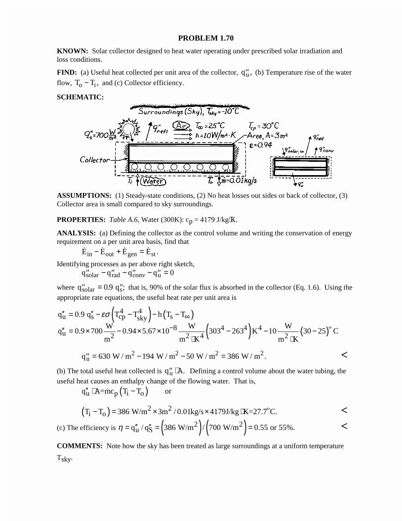
PROBLEM 1.70
KNOWN: Solar collector designed to heat water operating under prescribed solar irradiation andloss conditions.
FIND: (a) Useful heat collected per unit area of the collector, ′′qu , (b) Temperature rise of the water
flow, T To i− , and (c) Collector efficiency.
SCHEMATIC:
ASSUMPTIONS: (1) Steady-state conditions, (2) No heat losses out sides or back of collector, (3)Collector area is small compared to sky surroundings.
PROPERTIES: Table A.6, Water (300K): cp = 4179 J/kg⋅K.
ANALYSIS: (a) Defining the collector as the control volume and writing the conservation of energyrequirement on a per unit area basis, find that
.E E E Ein out gen st− + =Identifying processes as per above right sketch,
′′ − ′′ − ′′ − ′′ =q q q qsolar rad conv u 0
where ′′ = ′′q qsolar s0 9. ; that is, 90% of the solar flux is absorbed in the collector (Eq. 1.6). Using theappropriate rate equations, the useful heat rate per unit area is
( ) ( )
( ) ( )
4 4u s cp ssky
8 4 4 4u 2 2 4 2
q 0.9 q T T h T T
W W Wq 0.9 700 0.94 5.67 10 303 263 K 10 30 25 C
m m K m K
εσ ∞−
′′ ′′= − − − −
′′ = × − × × − − −⋅ ⋅
$
′′ = − − =q W / m W / m W / m W / mu2 2 2 2630 194 50 386 . <
(b) The total useful heat collected is ′′ ⋅q A.u Defining a control volume about the water tubing, theuseful heat causes an enthalpy change of the flowing water. That is,
( )u p i oq A=mc T T or′′ ⋅ −
( ) 2 2i oT T 386 W/m 3m / 0.01kg/s 4179J/kg K=27.7 C.− = × × ⋅ $ <
(c) The efficiency is ( ) ( )2 2u Sq / q 386 W/m / 700 W/m 0.55 or 55%.η ′′ ′′= = = <
COMMENTS: Note how the sky has been treated as large surroundings at a uniform temperature
Tsky.
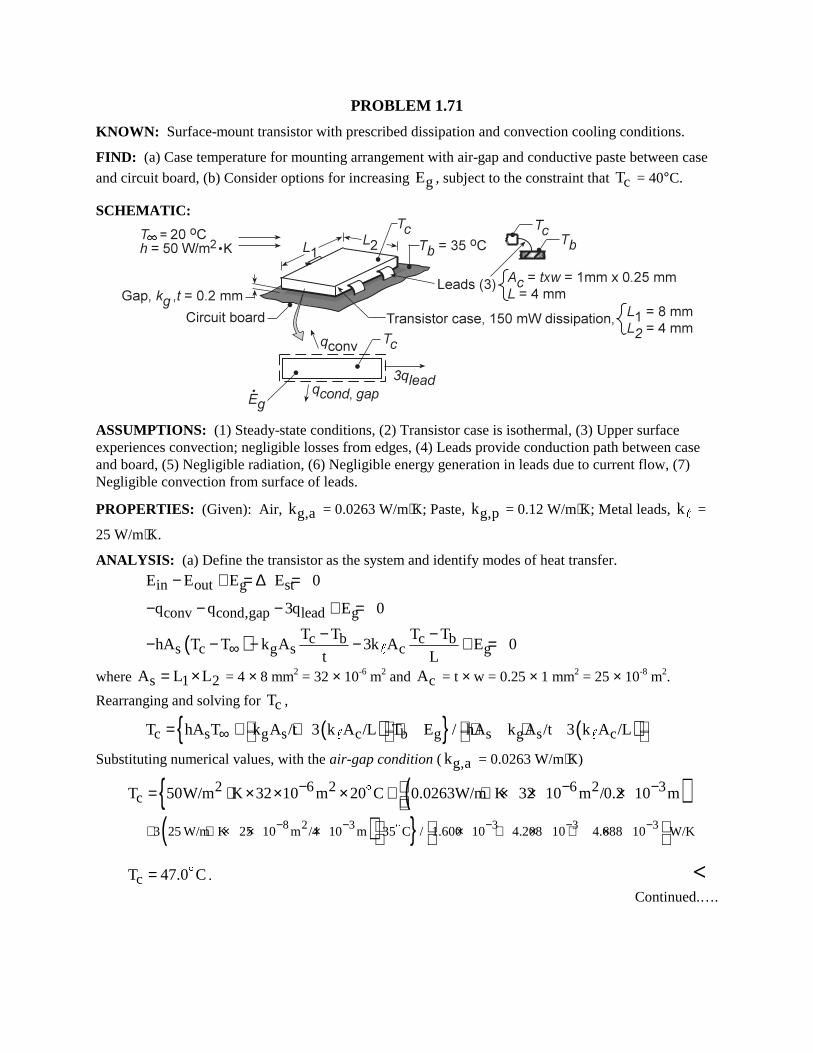
PROBLEM 1.71 KNOWN: Surface-mount transistor with prescribed dissipation and convection cooling conditions. FIND: (a) Case temperature for mounting arrangement with air-gap and conductive paste between case
and circuit board, (b) Consider options for increasing gE , subject to the constraint that cT = 40°C. SCHEMATIC:
ASSUMPTIONS: (1) Steady-state conditions, (2) Transistor case is isothermal, (3) Upper surface experiences convection; negligible losses from edges, (4) Leads provide conduction path between case and board, (5) Negligible radiation, (6) Negligible energy generation in leads due to current flow, (7) Negligible convection from surface of leads. PROPERTIES: (Given): Air, g,ak = 0.0263 W/m⋅K; Paste, g,pk = 0.12 W/m⋅K; Metal leads, k" =
25 W/m⋅K. ANALYSIS: (a) Define the transistor as the system and identify modes of heat transfer.
in out g stE E E E 0− + = ∆ =
conv cond,gap lead gq q 3q E 0− − − + =
( ) c b c bs c g s c g
T T T ThA T T k A 3k A E 0
t L∞− −− − − − + ="
where s 1 2A L L= × = 4 × 8 mm2 = 32 × 10-6 m2 and cA = t × w = 0.25 × 1 mm2 = 25 × 10-8 m2.
Rearranging and solving for cT ,
( ) ( )c s g s c b g s g s cT hA T k A /t 3 k A /L T E / hA k A /t 3 k A /L∞ = + + + + + " "
Substituting numerical values, with the air-gap condition ( g,ak = 0.0263 W/m⋅K)
( )2 6 2 6 2 3cT 50W/m K 32 10 m 20 C 0.0263W/m K 32 10 m /0.2 10 m− − −= ⋅ × × × + ⋅ × × ×
$
( ) 8 2 3 3 3 33 25 W/m K 25 10 m /4 10 m 35 C / 1.600 10 4.208 10 4.688 10 W/K− − − − −+ ⋅ × × × × + × + ×
$
cT 47.0 C= $ . <
Continued.….
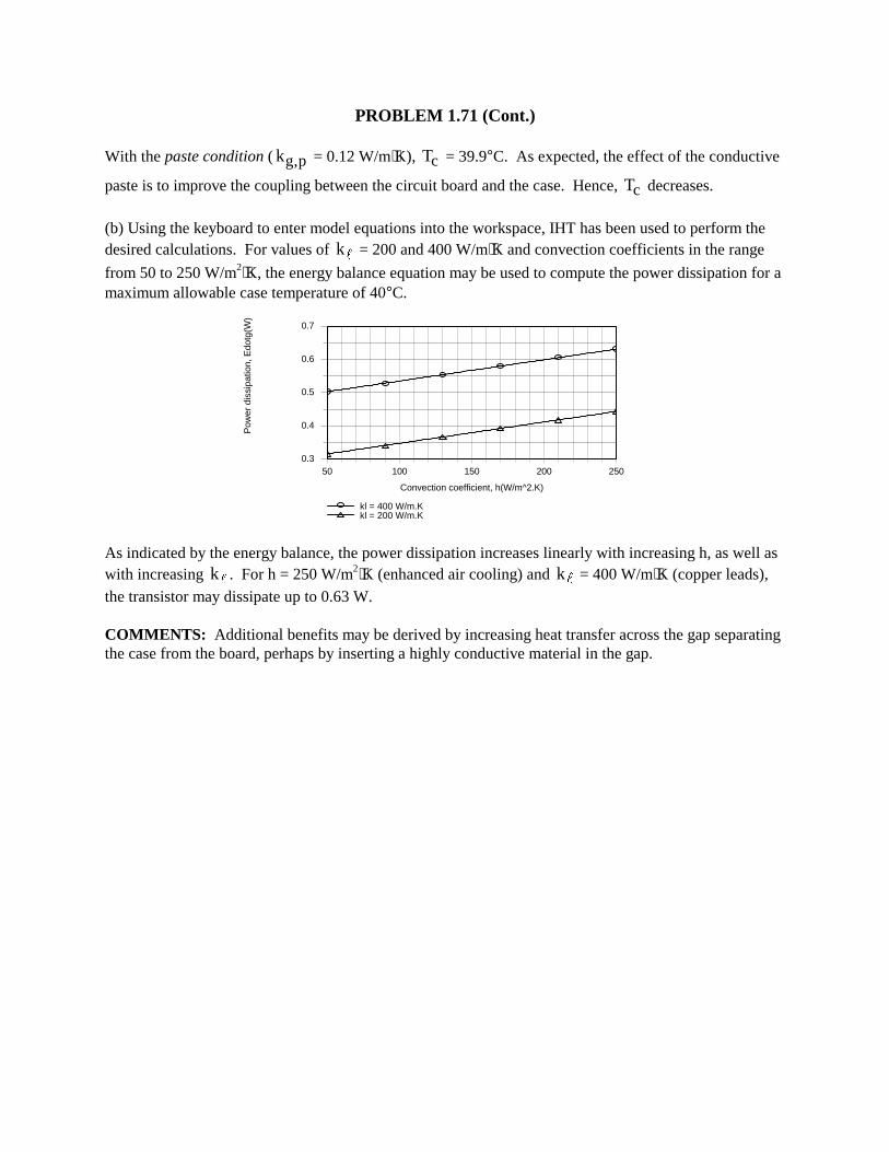
PROBLEM 1.71 (Cont.) With the paste condition ( g,pk = 0.12 W/m⋅K), cT = 39.9°C. As expected, the effect of the conductive
paste is to improve the coupling between the circuit board and the case. Hence, cT decreases.
(b) Using the keyboard to enter model equations into the workspace, IHT has been used to perform the desired calculations. For values of k" = 200 and 400 W/m⋅K and convection coefficients in the range
from 50 to 250 W/m2⋅K, the energy balance equation may be used to compute the power dissipation for a maximum allowable case temperature of 40°C.
50 100 150 200 250
Convection coefficient, h(W/m^2.K)
0.3
0.4
0.5
0.6
0.7
Pow
er d
issi
patio
n, E
dotg
(W)
kl = 400 W/m.Kkl = 200 W/m.K
As indicated by the energy balance, the power dissipation increases linearly with increasing h, as well as with increasing k" . For h = 250 W/m2⋅K (enhanced air cooling) and k" = 400 W/m⋅K (copper leads), the transistor may dissipate up to 0.63 W. COMMENTS: Additional benefits may be derived by increasing heat transfer across the gap separating the case from the board, perhaps by inserting a highly conductive material in the gap.
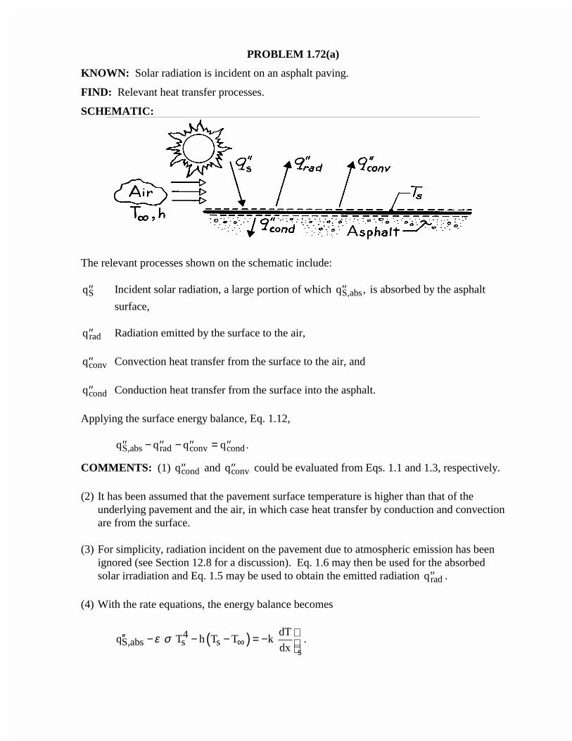
PROBLEM 1.72(a)
KNOWN: Solar radiation is incident on an asphalt paving.
FIND: Relevant heat transfer processes.
SCHEMATIC:
The relevant processes shown on the schematic include:
′′qS Incident solar radiation, a large portion of which ′′qS,abs, is absorbed by the asphalt
surface,
′′qrad Radiation emitted by the surface to the air,
′′qconv Convection heat transfer from the surface to the air, and
′′qcond Conduction heat transfer from the surface into the asphalt.
Applying the surface energy balance, Eq. 1.12,
′′ − ′′ − ′′ = ′′q q q qS,abs rad conv cond .
COMMENTS: (1) ′′qcond and ′′qconv could be evaluated from Eqs. 1.1 and 1.3, respectively.
(2) It has been assumed that the pavement surface temperature is higher than that of theunderlying pavement and the air, in which case heat transfer by conduction and convectionare from the surface.
(3) For simplicity, radiation incident on the pavement due to atmospheric emission has beenignored (see Section 12.8 for a discussion). Eq. 1.6 may then be used for the absorbedsolar irradiation and Eq. 1.5 may be used to obtain the emitted radiation ′′qrad .
(4) With the rate equations, the energy balance becomes
( )4S,abs s s
s
dTq T h T T k .
dxε σ ∞
′′ − − − = −
PROBLEM 1.72(b) KNOWN: Physical mechanism for microwave heating. FIND: Comparison of (a) cooking in a microwave oven with a conventional radiant or convection oven and (b) a microwave clothes dryer with a conventional dryer. (a) Microwave cooking occurs as a result of volumetric thermal energy generation throughout the food, without heating of the food container or the oven wall. Conventional cooking relies on radiant heat transfer from the oven walls and/or convection heat transfer from the air space to the surface of the food and subsequent heat transfer by conduction to the core of the food. Microwave cooking is more efficient and is achieved in less time. (b) In a microwave dryer, the microwave radiation would heat the water, but not the fabric, directly (the fabric would be heated indirectly by energy transfer from the water). By heating the water, energy would go directly into evaporation, unlike a conventional dryer where the walls and air are first heated electrically or by a gas heater, and thermal energy is subsequently transferred to the wet clothes. The microwave dryer would still require a rotating drum and air flow to remove the water vapor, but is able to operate more efficiently and at lower temperatures. For a more detailed description of microwave drying, see Mechanical Engineering, March 1993, page 120.
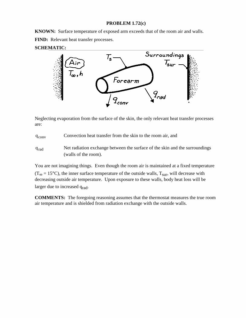
PROBLEM 1.72(c) KNOWN: Surface temperature of exposed arm exceeds that of the room air and walls. FIND: Relevant heat transfer processes. SCHEMATIC:
Neglecting evaporation from the surface of the skin, the only relevant heat transfer processes are: qconv Convection heat transfer from the skin to the room air, and qrad Net radiation exchange between the surface of the skin and the surroundings
(walls of the room). You are not imagining things. Even though the room air is maintained at a fixed temperature
(T∞ = 15°C), the inner surface temperature of the outside walls, Tsur, will decrease with decreasing outside air temperature. Upon exposure to these walls, body heat loss will be
larger due to increased qrad. COMMENTS: The foregoing reasoning assumes that the thermostat measures the true room air temperature and is shielded from radiation exchange with the outside walls.
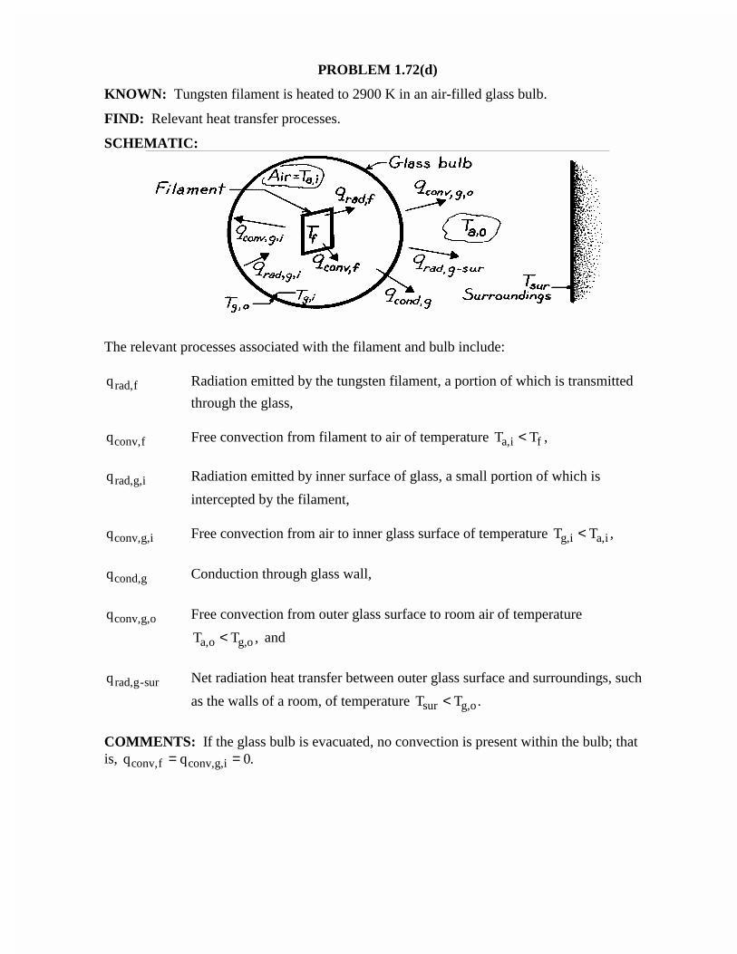
PROBLEM 1.72(d)
KNOWN: Tungsten filament is heated to 2900 K in an air-filled glass bulb.
FIND: Relevant heat transfer processes.
SCHEMATIC:
The relevant processes associated with the filament and bulb include:
qrad,f Radiation emitted by the tungsten filament, a portion of which is transmitted
through the glass,
qconv,f Free convection from filament to air of temperature T Ta,i f< ,
qrad,g,i Radiation emitted by inner surface of glass, a small portion of which is
intercepted by the filament,
qconv,g,i Free convection from air to inner glass surface of temperature T Tg,i a,i< ,
qcond,g Conduction through glass wall,
qconv,g,o Free convection from outer glass surface to room air of temperature
T Ta,o g,o< , and
qrad,g-sur Net radiation heat transfer between outer glass surface and surroundings, such
as the walls of a room, of temperature T Tsur g,o< .
COMMENTS: If the glass bulb is evacuated, no convection is present within the bulb; thatis, q qconv,f conv,g,i= = 0.
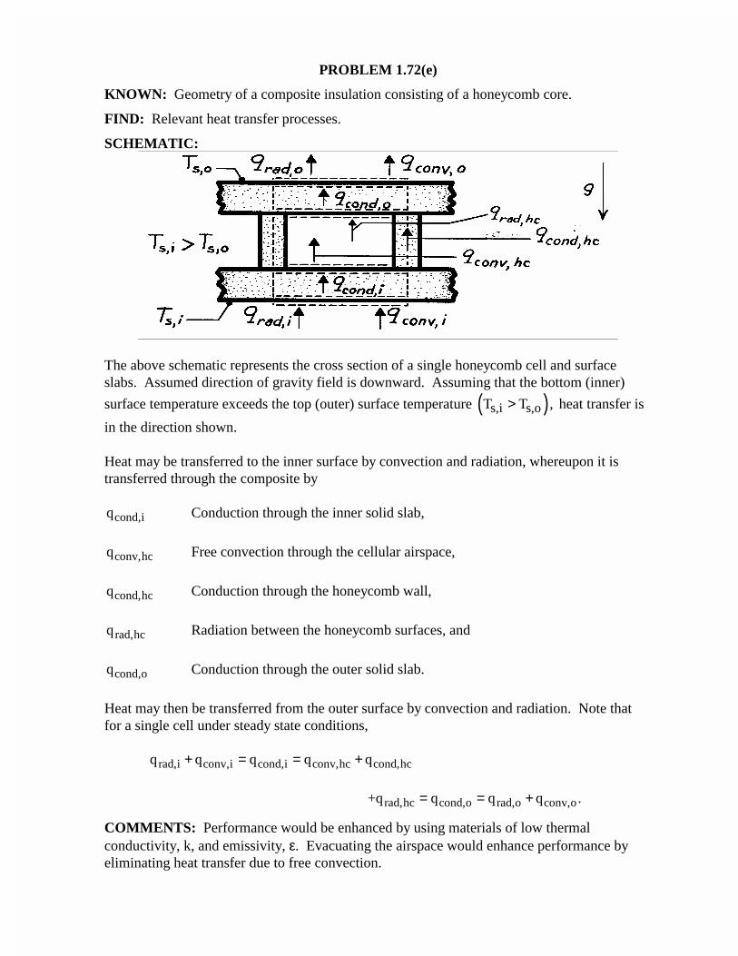
PROBLEM 1.72(e)
KNOWN: Geometry of a composite insulation consisting of a honeycomb core.
FIND: Relevant heat transfer processes.
SCHEMATIC:
The above schematic represents the cross section of a single honeycomb cell and surfaceslabs. Assumed direction of gravity field is downward. Assuming that the bottom (inner)
surface temperature exceeds the top (outer) surface temperature ( )s,i s,oT T ,> heat transfer is
in the direction shown.
Heat may be transferred to the inner surface by convection and radiation, whereupon it istransferred through the composite by
qcond,i Conduction through the inner solid slab,
qconv,hc Free convection through the cellular airspace,
qcond,hc Conduction through the honeycomb wall,
qrad,hc Radiation between the honeycomb surfaces, and
qcond,o Conduction through the outer solid slab.
Heat may then be transferred from the outer surface by convection and radiation. Note thatfor a single cell under steady state conditions,
q q q q qrad,i conv,i cond,i conv,hc cond,hc+ = = +
+q q q qrad,hc cond,o rad,o conv,o= = + .
COMMENTS: Performance would be enhanced by using materials of low thermalconductivity, k, and emissivity, ε. Evacuating the airspace would enhance performance byeliminating heat transfer due to free convection.
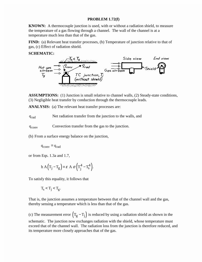
PROBLEM 1.72(f)
KNOWN: A thermocouple junction is used, with or without a radiation shield, to measurethe temperature of a gas flowing through a channel. The wall of the channel is at atemperature much less than that of the gas.
FIND: (a) Relevant heat transfer processes, (b) Temperature of junction relative to that ofgas, (c) Effect of radiation shield.
SCHEMATIC:
ASSUMPTIONS: (1) Junction is small relative to channel walls, (2) Steady-state conditions,(3) Negligible heat transfer by conduction through the thermocouple leads.
ANALYSIS: (a) The relevant heat transfer processes are:
qrad Net radiation transfer from the junction to the walls, and
qconv Convection transfer from the gas to the junction.
(b) From a surface energy balance on the junction,
q qconv rad=
or from Eqs. 1.3a and 1.7,
( ) ( )4 4j g sjh A T T A T T .ε σ− = −
To satisfy this equality, it follows that
T T Ts j g< < .
That is, the junction assumes a temperature between that of the channel wall and the gas,thereby sensing a temperature which is less than that of the gas.
(c) The measurement error ( )g jT T− is reduced by using a radiation shield as shown in the
schematic. The junction now exchanges radiation with the shield, whose temperature mustexceed that of the channel wall. The radiation loss from the junction is therefore reduced, andits temperature more closely approaches that of the gas.
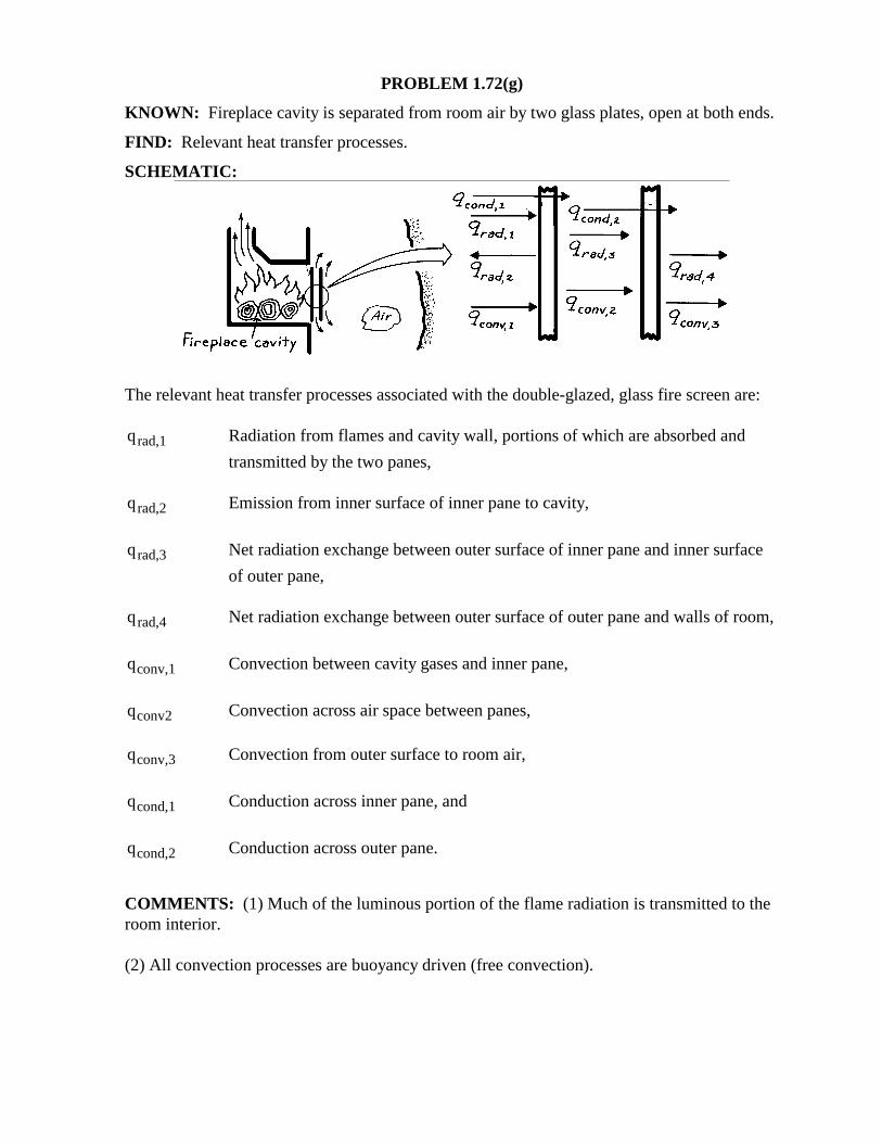
PROBLEM 1.72(g) KNOWN: Fireplace cavity is separated from room air by two glass plates, open at both ends. FIND: Relevant heat transfer processes. SCHEMATIC:
The relevant heat transfer processes associated with the double-glazed, glass fire screen are: qrad,1 Radiation from flames and cavity wall, portions of which are absorbed and
transmitted by the two panes, qrad,2 Emission from inner surface of inner pane to cavity,
qrad,3 Net radiation exchange between outer surface of inner pane and inner surface
of outer pane, qrad,4 Net radiation exchange between outer surface of outer pane and walls of room,
qconv,1 Convection between cavity gases and inner pane,
qconv2 Convection across air space between panes, qconv,3 Convection from outer surface to room air,
qcond,1 Conduction across inner pane, and
qcond,2 Conduction across outer pane.
COMMENTS: (1) Much of the luminous portion of the flame radiation is transmitted to the room interior. (2) All convection processes are buoyancy driven (free convection).

PROBLEM 1.73(a) KNOWN: Room air is separated from ambient air by one or two glass panes. FIND: Relevant heat transfer processes. SCHEMATIC:
The relevant processes associated with single (above left schematic) and double (above right schematic) glass panes include. qconv,1 Convection from room air to inner surface of first pane,
qrad,1 Net radiation exchange between room walls and inner surface of first pane,
qcond,1 Conduction through first pane,
qconv,s Convection across airspace between panes,
qrad,s Net radiation exchange between outer surface of first pane and inner surface of
second pane (across airspace), qcond,2 Conduction through a second pane,
qconv,2 Convection from outer surface of single (or second) pane to ambient air,
qrad,2 Net radiation exchange between outer surface of single (or second) pane and
surroundings such as the ground, and qS Incident solar radiation during day; fraction transmitted to room is smaller for
double pane. COMMENTS: Heat loss from the room is significantly reduced by the double pane construction.
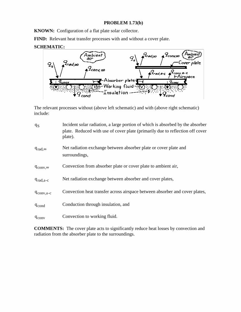
PROBLEM 1.73(b) KNOWN: Configuration of a flat plate solar collector. FIND: Relevant heat transfer processes with and without a cover plate. SCHEMATIC:
The relevant processes without (above left schematic) and with (above right schematic) include: qS Incident solar radiation, a large portion of which is absorbed by the absorber
plate. Reduced with use of cover plate (primarily due to reflection off cover plate).
qrad,∞ Net radiation exchange between absorber plate or cover plate and
surroundings, qconv,∞ Convection from absorber plate or cover plate to ambient air,
qrad,a-c Net radiation exchange between absorber and cover plates,
qconv,a-c Convection heat transfer across airspace between absorber and cover plates,
qcond Conduction through insulation, and qconv Convection to working fluid. COMMENTS: The cover plate acts to significantly reduce heat losses by convection and radiation from the absorber plate to the surroundings.
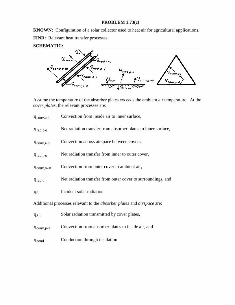
PROBLEM 1.73(c) KNOWN: Configuration of a solar collector used to heat air for agricultural applications. FIND: Relevant heat transfer processes. SCHEMATIC:
Assume the temperature of the absorber plates exceeds the ambient air temperature. At the cover plates, the relevant processes are: qconv,a-i Convection from inside air to inner surface,
qrad,p-i Net radiation transfer from absorber plates to inner surface,
qconv,i-o Convection across airspace between covers,
qrad,i-o Net radiation transfer from inner to outer cover,
qconv,o-∞ Convection from outer cover to ambient air,
qrad,o Net radiation transfer from outer cover to surroundings, and
qS Incident solar radiation. Additional processes relevant to the absorber plates and airspace are: qS,t Solar radiation transmitted by cover plates,
qconv,p-a Convection from absorber plates to inside air, and
qcond Conduction through insulation.
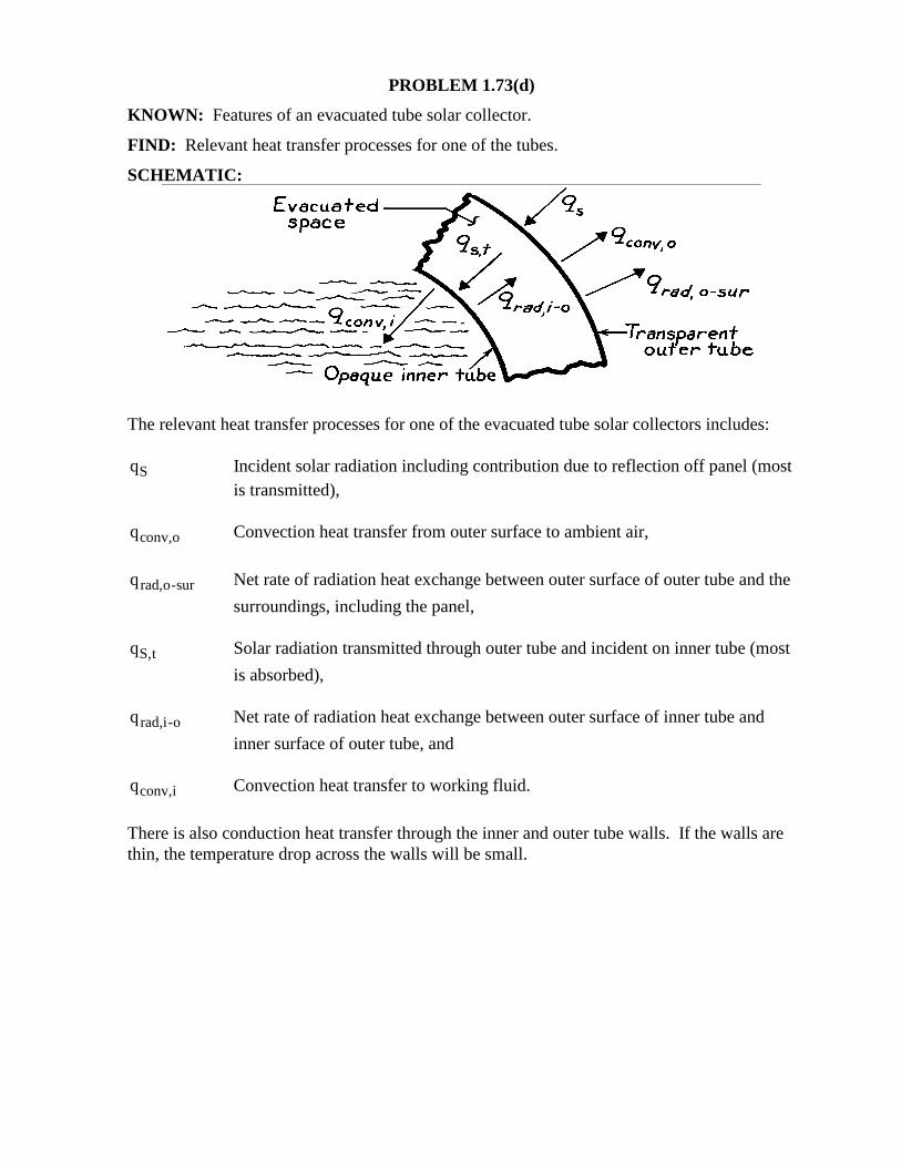
PROBLEM 1.73(d) KNOWN: Features of an evacuated tube solar collector. FIND: Relevant heat transfer processes for one of the tubes. SCHEMATIC:
The relevant heat transfer processes for one of the evacuated tube solar collectors includes: qS Incident solar radiation including contribution due to reflection off panel (most
is transmitted), qconv,o Convection heat transfer from outer surface to ambient air,
qrad,o-sur Net rate of radiation heat exchange between outer surface of outer tube and the
surroundings, including the panel, qS,t Solar radiation transmitted through outer tube and incident on inner tube (most
is absorbed), qrad,i-o Net rate of radiation heat exchange between outer surface of inner tube and
inner surface of outer tube, and qconv,i Convection heat transfer to working fluid.
There is also conduction heat transfer through the inner and outer tube walls. If the walls are thin, the temperature drop across the walls will be small.