Embed Size (px)
Citation preview

1
BY CHRISTOPHER F. SIKORA
© Copyright 2013 Christopher Sikora

2
This manual is for educational purposes only. It may be printed, but not resold for profit for its content.
SolidWorks is a registered trademark of Dassault Systèmes SolidWorks Corp. SolidWorks is a product name of Dassault Systèmes SolidWorks Corp.
ACIS is a registered trademark of Dassault Systèmes SolidWorks Corp. IGES™ Access Library is a trademark of IGES Data Analysis, Inc. Other brand or product names are trademarks or registered trademarks of their respective holders. The information discussed in this document is subject to change without notice and should not be considered commitments by Christopher F. Sikora. The software discussed in this document is furnished under a license and may be used or copied only in accordance with the terms of this license.

3
COURSE SYLLABUS
SolidWorks Basics 120
Course Description: SolidWorks Basics 3 credit hours
Exploration of the theory and application of solid modeling techniques for product design and manufacturing. Prerequisite: Intro to Engineering Drawings 101 or consent of instructor. (2 lecture hours, 2 lab hours)
Course Objectives: Provide the student with the knowledge and practical experience in the areas of 3D CAD modeling of parts, assemblies, and the creation of mechanical drawings from the models.
Textbook SolidWorks Basics free/pdf. and videos provided on www.vertanux1.com
Evaluation Scale: A 90% to 100%
B 80% to 89%
C 70% to 79%
D 60% to 69%
F Below 60%
Points: Exercises 300 pts
Mid Term 300 pts
Final 300 pts
Labs 100 pts
Total 1000 pts

4
General Course Outline
Date Week Topic 1. Introduction to the Interface Lecture
Modeling Theory - Sketching and Base Feature Geometry Creation.
2. Revolved Features and Mirroring 3. Part Modeling
Secondary Features. Fillets, Chamfers, Draft, Patterns, Mirroring.
4. Sweeps, and Circular Patterns 5. Modeling Quiz and CAD Administration
6. Building Assemblies (Bottom-Up method “BU”) 7. Creating Drawings. Review for Mid Term 8. Mid Term Exam 9. 3D Curves and Sweeps 10. Swept Blends/Lofting 11. Assemblies Creation (Top-Down Method “TD”) 12. Assembly/Part Editing (“TD” & “BU” Methods) 13. Assembly Project 14. Assembly Project (continued) 15. Lab time to complete exercise, Review for Final Exam 16. Final Exam

5
Exercises 1. Introduction to the Interface
Modeling Theory - Sketching and Base Feature Geometry Creation.
2. Part Modeling
Revolved Method
3. Secondary Feature Modeling (Draft, Offsetting Entities, Filleting)
4. Advanced part Modeling (Sweeps, and Circular Patterns)
5. Bottom-Up Assembly Modeling
6. Creating Drawings
6
7. Projected Curves and Sweeping
8. Lofting
9. Introduction to Top-Down Assembly Modeling.
10. Top-Down Assembly Editing
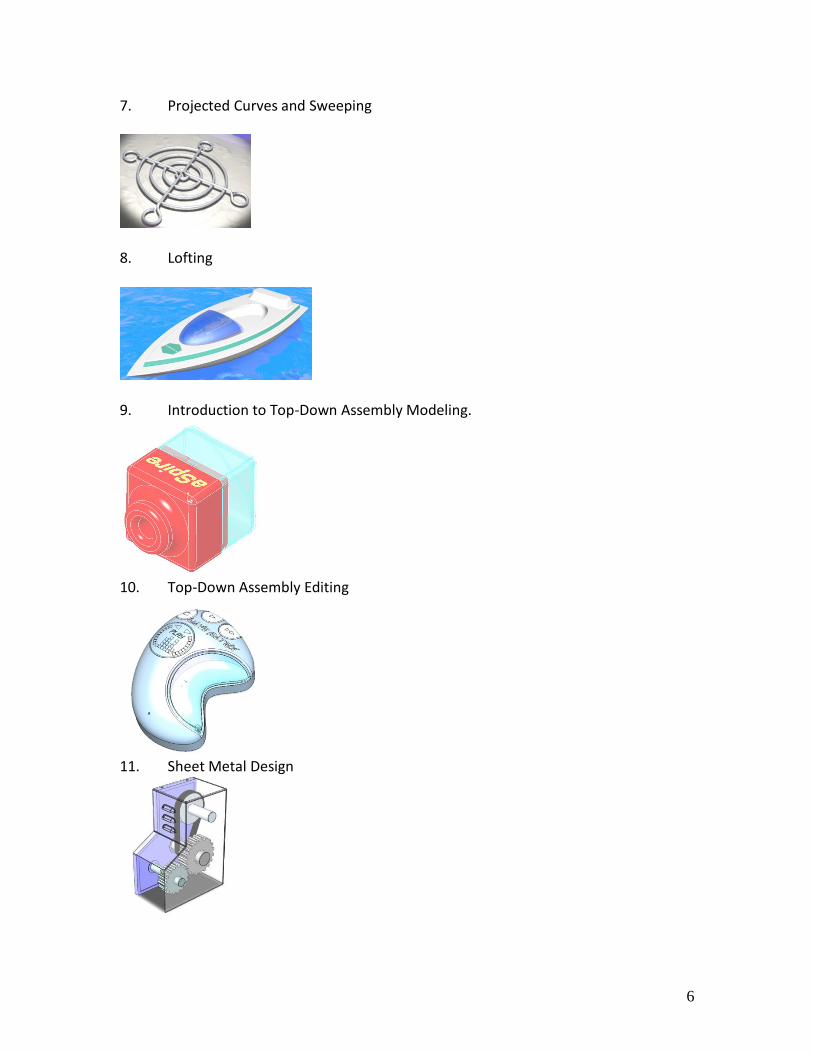
11. Sheet Metal Design
7
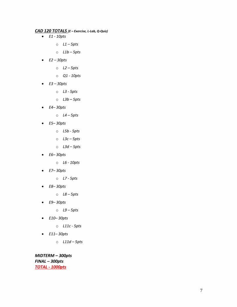
CAD 120 TOTALS (E – Exercise, L-Lab, Q-Quiz) E1 - 10pts
o L1 – 5pts
o L1b – 5pts
E2 – 30pts
o L2 – 5pts
o Q1 - 10pts
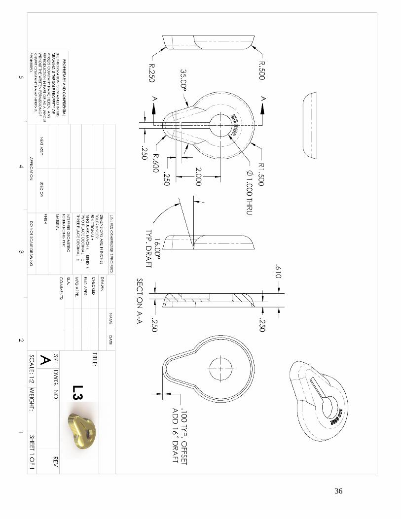
E3 – 30pts
o L3 - 5pts
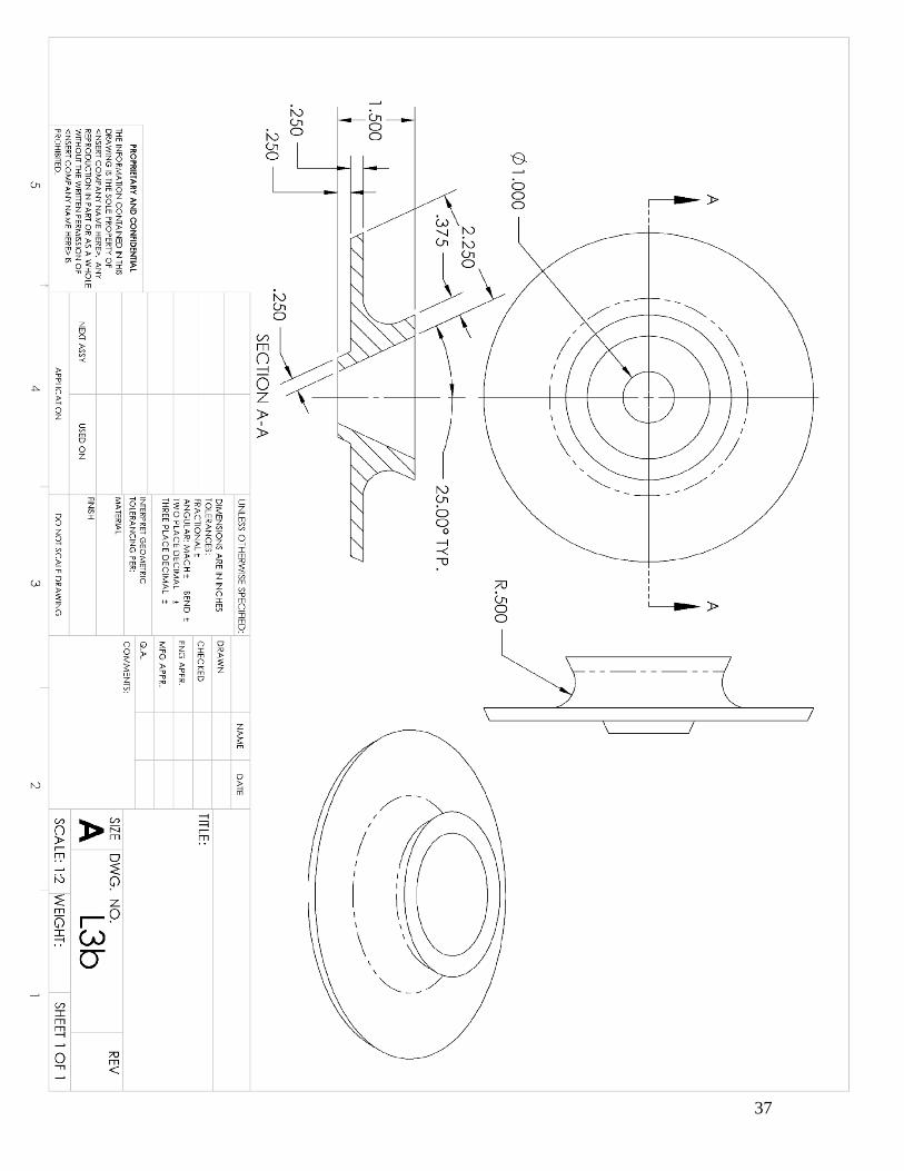
o L3b – 5pts
E4– 30pts
o L4 – 5pts
E5– 30pts
o L5b - 5pts
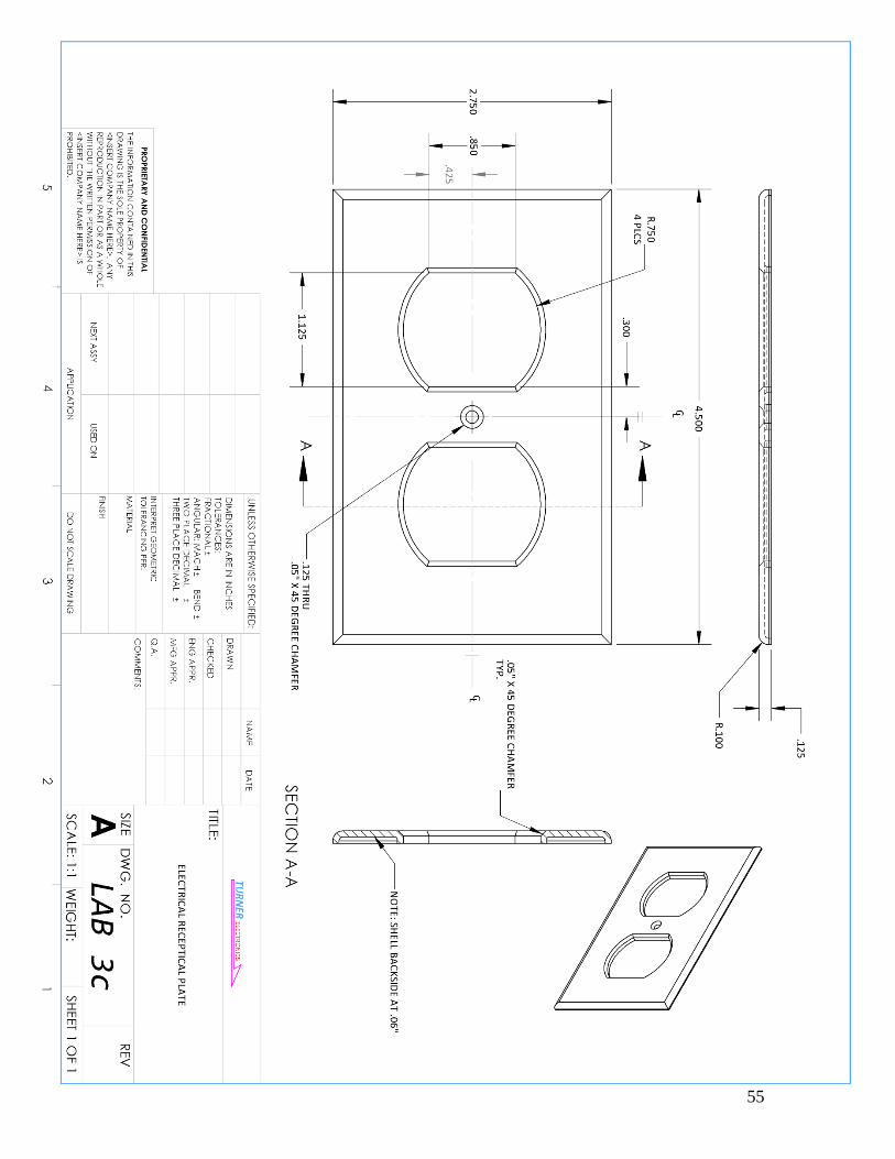
o L3c – 5pts
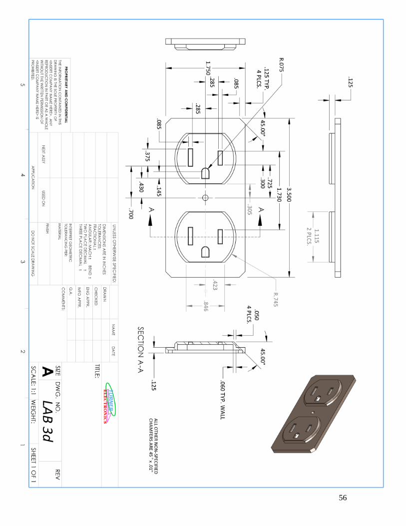
o L3d – 5pts
E6– 30pts
o L6 - 10pts
E7– 30pts
o L7 - 5pts
E8– 30pts
o L8 – 5pts
E9– 30pts
o L9 – 5pts
E10– 30pts
o L11c - 5pts
E11– 30pts
o L11d – 5pts
MIDTERM – 300pts FINAL – 300pts TOTAL - 1000pts
8
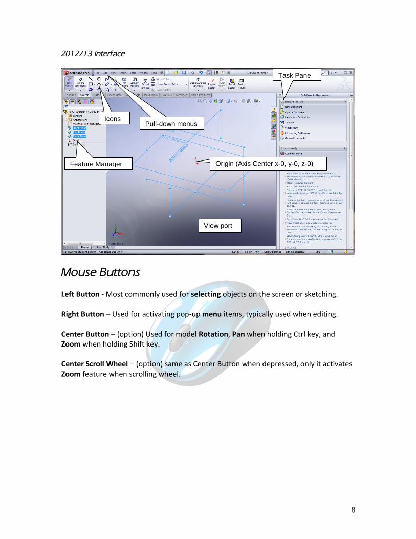
2012/13 Interface
Mouse Buttons Left Button - Most commonly used for selecting objects on the screen or sketching. Right Button – Used for activating pop-up menu items, typically used when editing. Center Button – (option) Used for model Rotation, Pan when holding Ctrl key, and Zoom when holding Shift key. Center Scroll Wheel – (option) same as Center Button when depressed, only it activates Zoom feature when scrolling wheel.
Origin (Axis Center x-0, y-0, z-0)
Pull-down menus
Feature Manager
Icons
View port
Task Pane
9
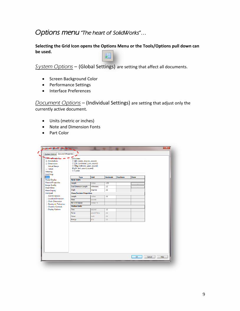
Options menu “The heart of SolidWorks”… Selecting the Grid Icon opens the Options Menu or the Tools/Options pull down can be used.
System Options – (Global Settings) are setting that affect all documents.
Screen Background Color
Performance Settings
Interface Preferences
Document Options – (Individual Settings) are setting that adjust only the
currently active document.
Units (metric or inches)
Note and Dimension Fonts
Part Color
10
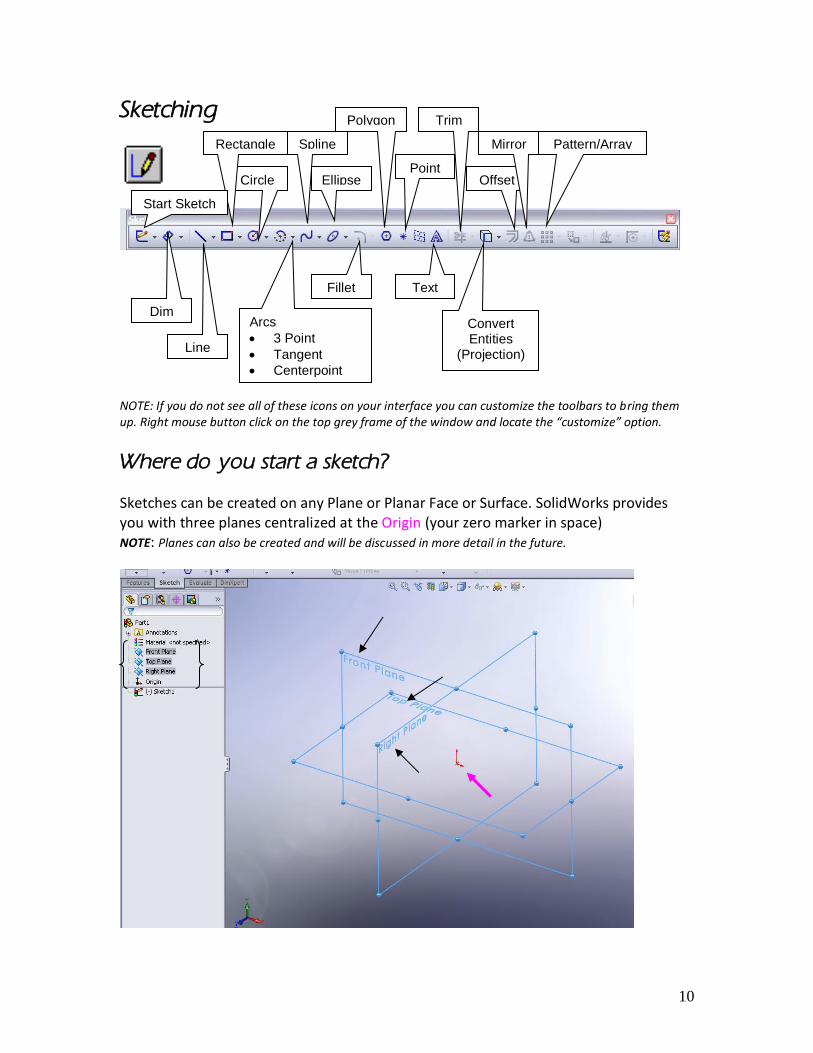
Sketching
NOTE: If you do not see all of these icons on your interface you can customize the toolbars to bring them up. Right mouse button click on the top grey frame of the window and locate the “customize” option.
Where do you start a sketch? Sketches can be created on any Plane or Planar Face or Surface. SolidWorks provides you with three planes centralized at the Origin (your zero marker in space) NOTE: Planes can also be created and will be discussed in more detail in the future.
Line
Arcs
3 Point
Tangent
Centerpoint
Circle
Spline
Polygon
Rectangle
Trim
Offset
Mirror
Fillet
Convert Entities
(Projection)
Point Ellipse
Pattern/Array
Dim
Text
Start Sketch
11
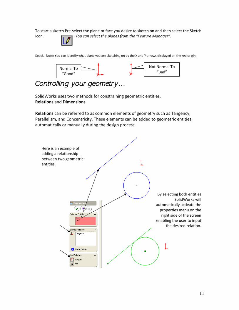
To start a sketch Pre-select the plane or face you desire to sketch on and then select the Sketch Icon. NOTE: You can select the planes from the “Feature Manager”. Special Note: You can identify what plane you are sketching on by the X and Y arrows displayed on the red origin.
Controlling your geometry… SolidWorks uses two methods for constraining geometric entities. Relations and Dimensions Relations can be referred to as common elements of geometry such as Tangency, Parallelism, and Concentricity. These elements can be added to geometric entities automatically or manually during the design process.
Normal To “Good”
Not Normal To “Bad”
Here is an example of adding a relationship between two geometric entities.
By selecting both entities SolidWorks will
automatically activate the properties menu on the right side of the screen
enabling the user to input the desired relation.
12
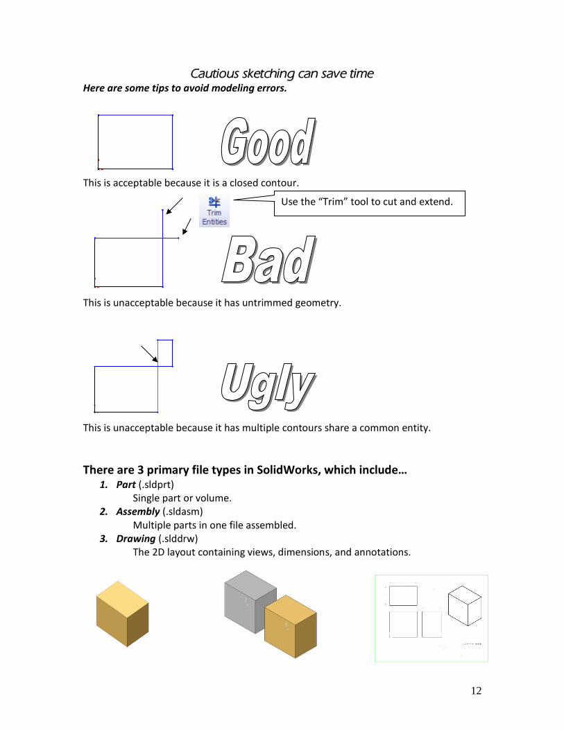
Cautious sketching can save time Here are some tips to avoid modeling errors.
This is acceptable because it is a closed contour.
This is unacceptable because it has untrimmed geometry.
This is unacceptable because it has multiple contours share a common entity.
There are 3 primary file types in SolidWorks, which include… 1. Part (.sldprt)
Single part or volume. 2. Assembly (.sldasm)
Multiple parts in one file assembled. 3. Drawing (.slddrw)
The 2D layout containing views, dimensions, and annotations.
Use the “Trim” tool to cut and extend.
13
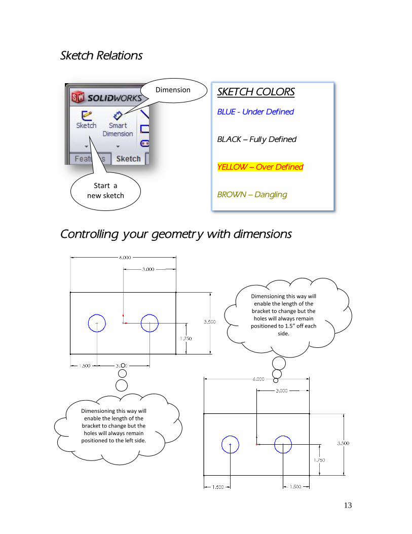
Sketch Relations
Controlling your geometry with dimensions
Dimension
Start a new sketch
SKETCH COLORS BLUE - Under Defined BLACK – Fully Defined YELLOW – Over Defined BROWN – Dangling
Dimensioning this way will enable the length of the
bracket to change but the holes will always remain
positioned to the left side.
Dimensioning this way will enable the length of the
bracket to change but the holes will always remain
positioned to 1.5” off each side.

14
Solid Modeling Basics Layer Cake method
Extruded Boss/Base (Creates/Adds material)
Extruded Cut (Removes material) Ingredients:
Profile
Revolve method
Revolve Boss/Base (Creates/Adds material)
Revolve Cut (Removes material) Ingredients:
Profile
Center Line (Note: The profile cannot cross over the center line!)
15
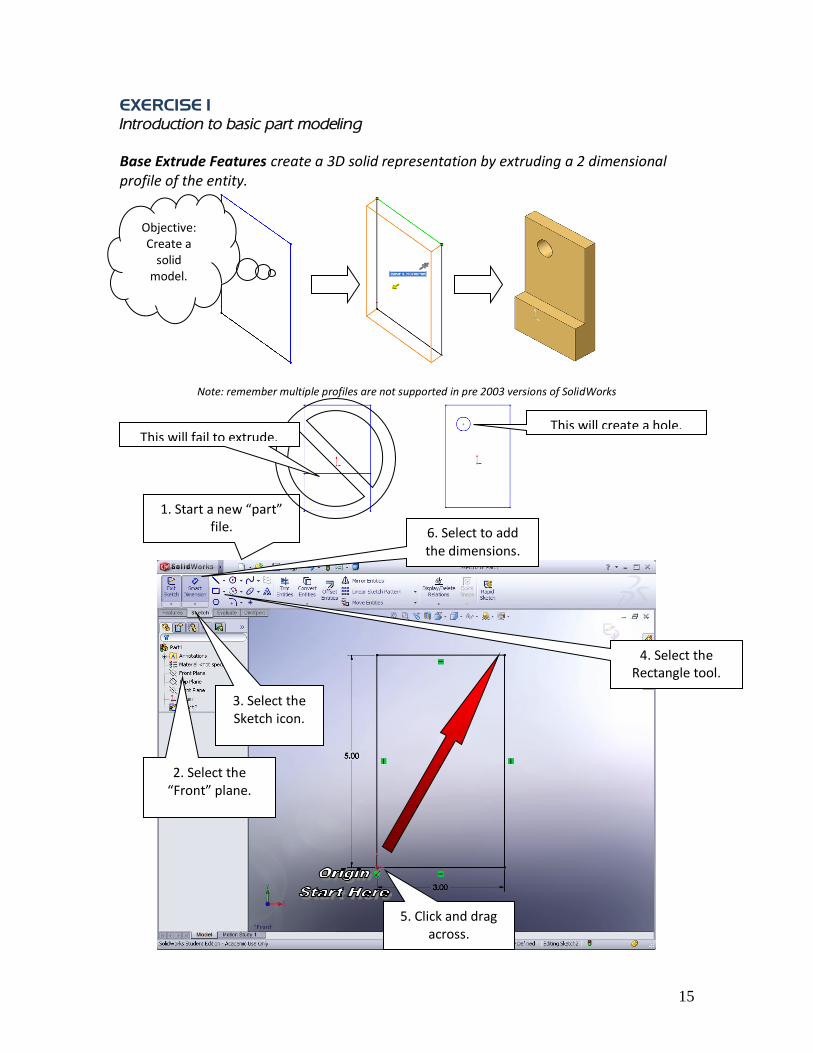
EXERCISE 1
Introduction to basic part modeling
Base Extrude Features create a 3D solid representation by extruding a 2 dimensional profile of the entity.
Note: remember multiple profiles are not supported in pre 2003 versions of SolidWorks
2. Select the “Front” plane.
4. Select the Rectangle tool.
6. Select to add the dimensions.
1. Start a new “part” file.
Objective: Create a
solid model.
This will create a hole. This will fail to extrude.
3. Select the Sketch icon.
5. Click and drag across.
16
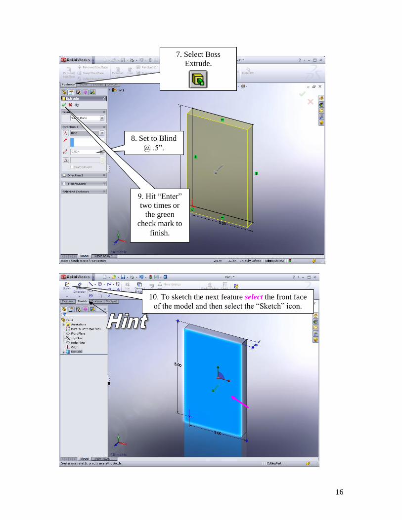
7. Select Boss
Extrude.
8. Set to Blind
@ .5”.
9. Hit “Enter”
two times or
the green
check mark to
finish.
10. To sketch the next feature select the front face
of the model and then select the “Sketch” icon.
17
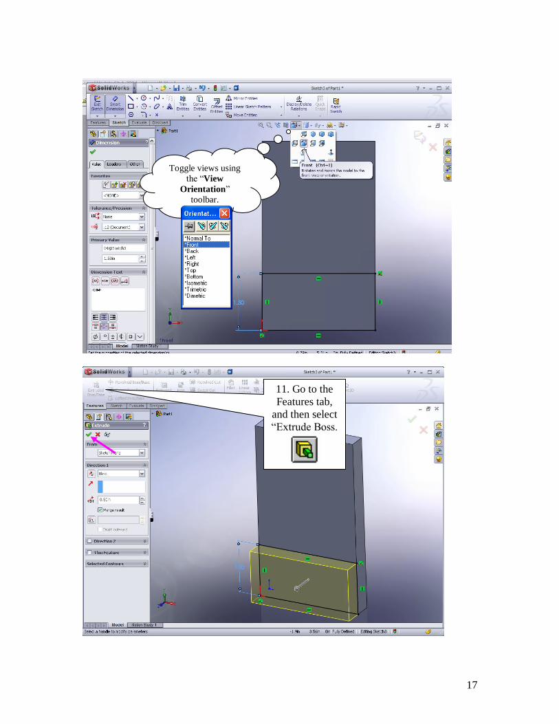
Toggle views using
the “View
Orientation”
toolbar.
Fast Key: Spacebar
11. Go to the
Features tab,
and then select
“Extrude Boss.
18
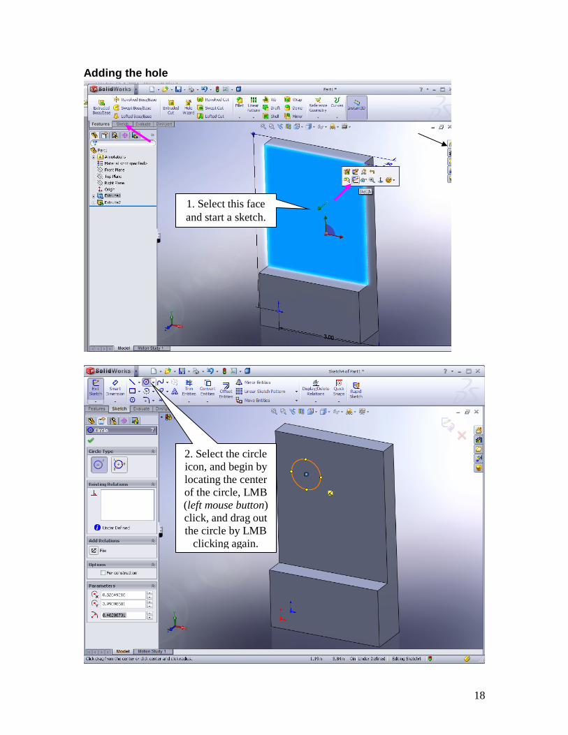
Adding the hole
1. Select this face
and start a sketch.
2. Select the circle
icon, and begin by
locating the center
of the circle, LMB
(left mouse button)
click, and drag out
the circle by LMB
clicking again.

19
4. Select the
Extrude Cut
icon.
5. Select the
“Through All”
option.
3. Using
“Smart
Dimension”
add the shown
dimensions.
20
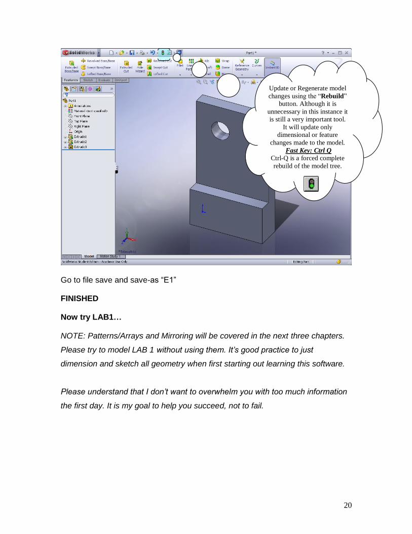
Go to file save and save-as “E1” FINISHED Now try LAB1… NOTE: Patterns/Arrays and Mirroring will be covered in the next three chapters.
Please try to model LAB 1 without using them. It’s good practice to just
dimension and sketch all geometry when first starting out learning this software.
Please understand that I don’t want to overwhelm you with too much information
the first day. It is my goal to help you succeed, not to fail.
Update or Regenerate model
changes using the “Rebuild”
button. Although it is
unnecessary in this instance it
is still a very important tool.
It will update only
dimensional or feature
changes made to the model.
Fast Key: Ctrl Q
Ctrl-Q is a forced complete
rebuild of the model tree.
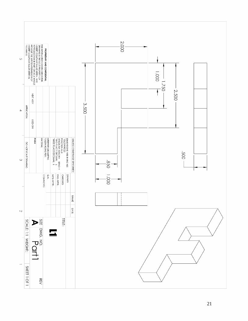
21

22
23
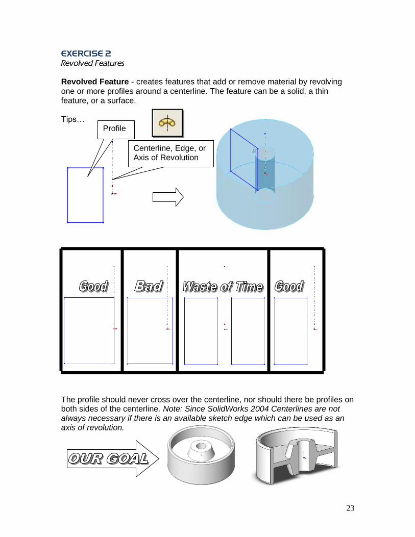
EXERCISE 2
Revolved Features Revolved Feature - creates features that add or remove material by revolving one or more profiles around a centerline. The feature can be a solid, a thin feature, or a surface. Tips…
The profile should never cross over the centerline, nor should there be profiles on both sides of the centerline. Note: Since SolidWorks 2004 Centerlines are not always necessary if there is an available sketch edge which can be used as an axis of revolution.
Profile
Centerline, Edge, or Axis of Revolution
24
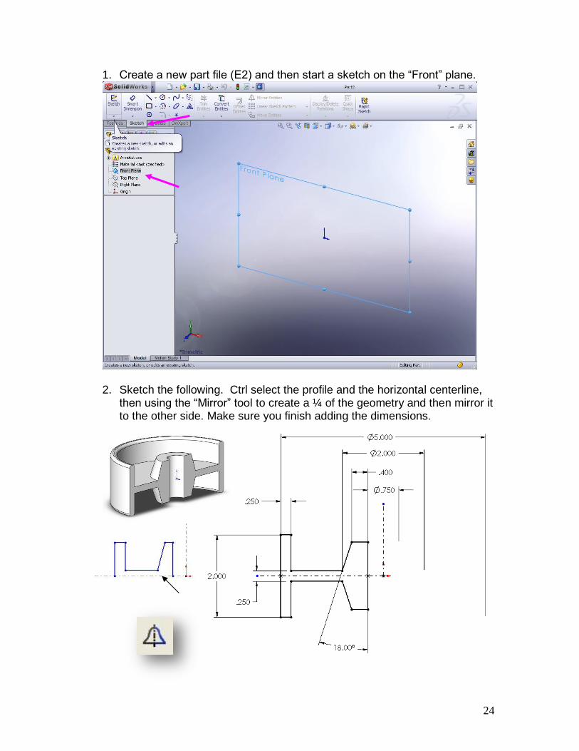
1. Create a new part file (E2) and then start a sketch on the “Front” plane.
2. Sketch the following. Ctrl select the profile and the horizontal centerline,
then using the “Mirror” tool to create a ¼ of the geometry and then mirror it to the other side. Make sure you finish adding the dimensions.
25
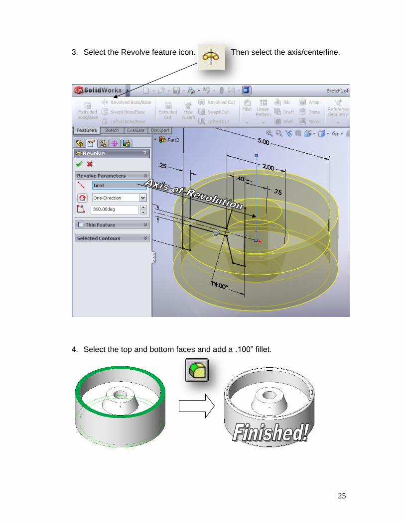
3. Select the Revolve feature icon. Then select the axis/centerline.
4. Select the top and bottom faces and add a .100” fillet.
26
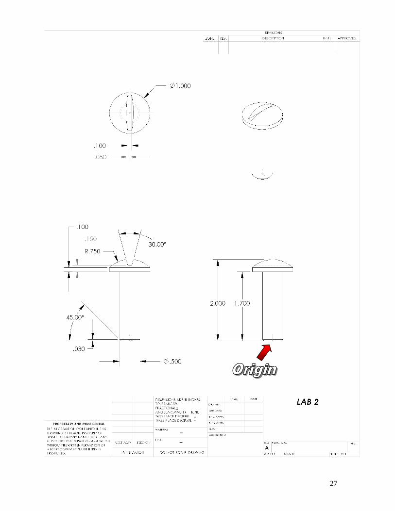
27

28
29
EXERCISE 3
Secondary Feature Modeling
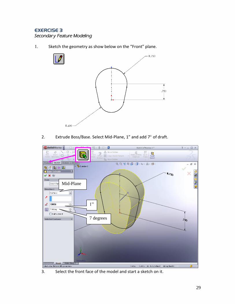
1. Sketch the geometry as show below on the “Front” plane.
2. Extrude Boss/Base. Select Mid-Plane, 1” and add 7 of draft.
3. Select the front face of the model and start a sketch on it.
Mid-Plane
1”
7 degrees
30
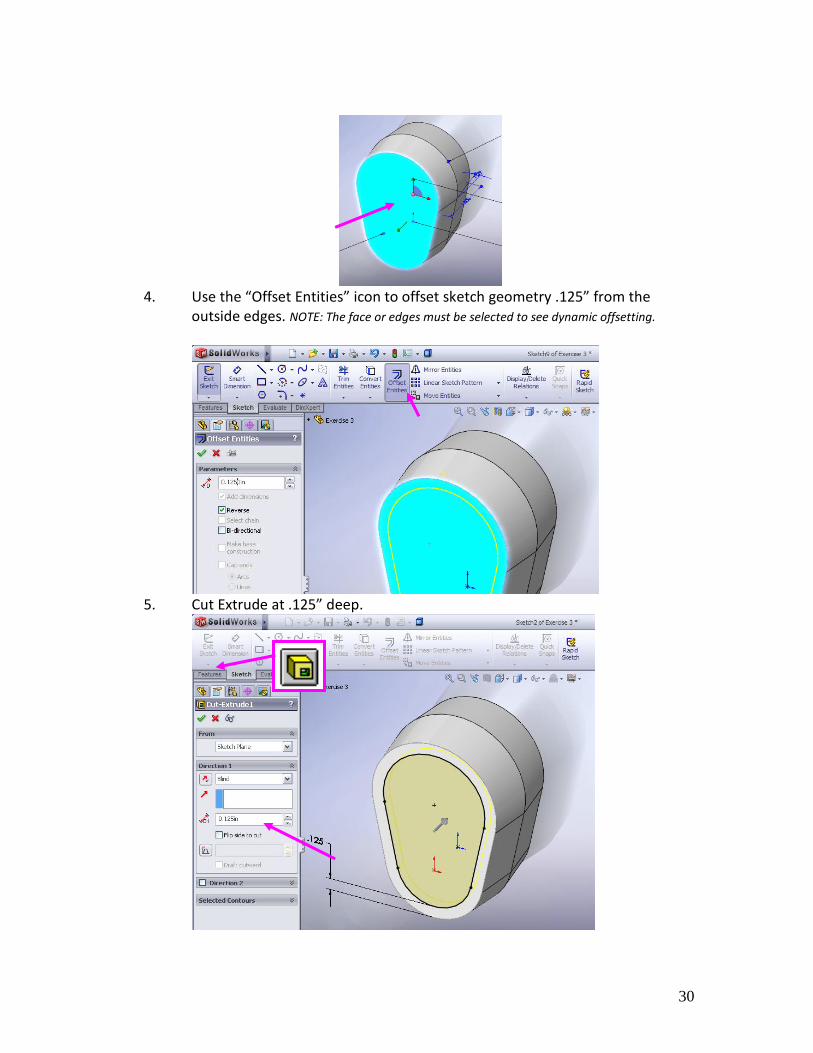
4. Use the “Offset Entities” icon to offset sketch geometry .125” from the
outside edges. NOTE: The face or edges must be selected to see dynamic offsetting.
5. Cut Extrude at .125” deep.
31
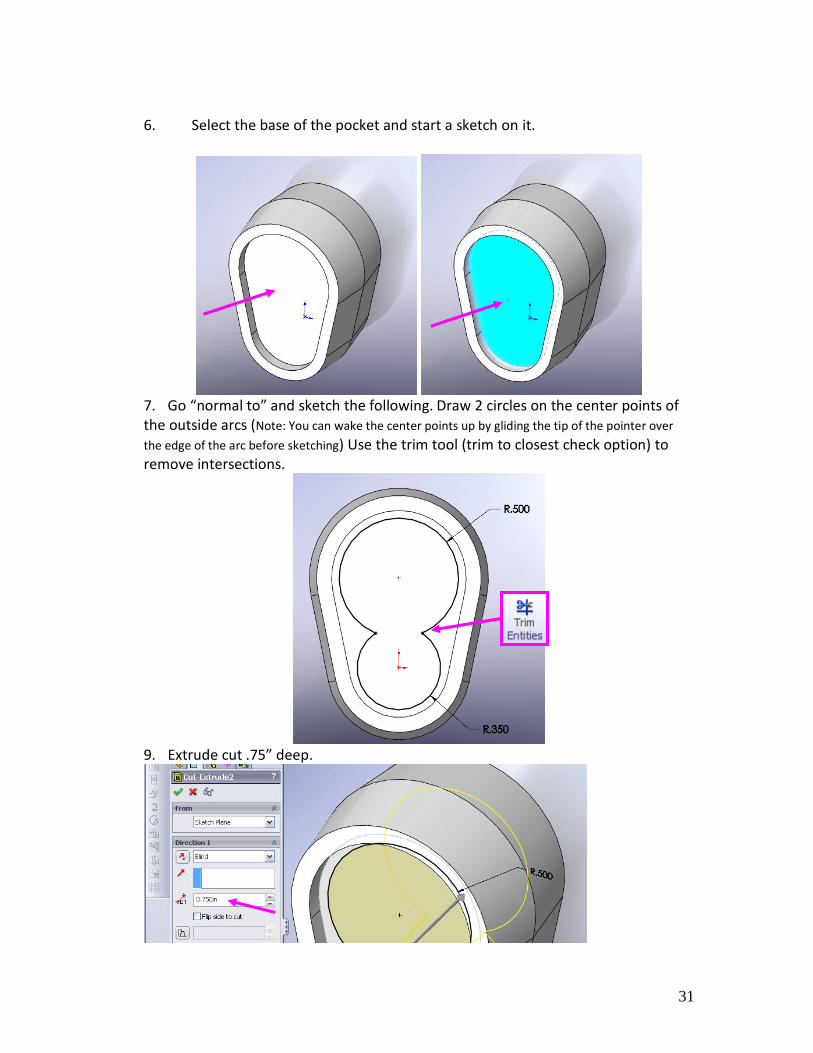
6. Select the base of the pocket and start a sketch on it.
7. Go “normal to” and sketch the following. Draw 2 circles on the center points of the outside arcs (Note: You can wake the center points up by gliding the tip of the pointer over
the edge of the arc before sketching) Use the trim tool (trim to closest check option) to remove intersections.
9. Extrude cut .75” deep.
32
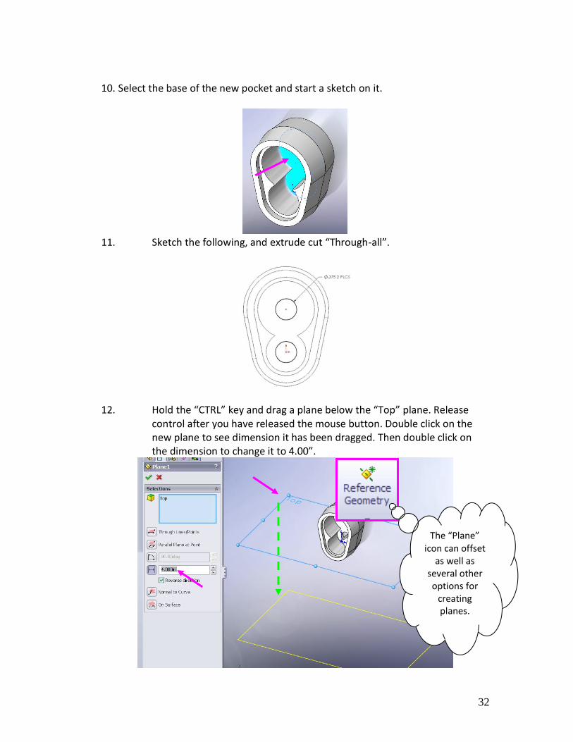
10. Select the base of the new pocket and start a sketch on it.
11. Sketch the following, and extrude cut “Through-all”.
12. Hold the “CTRL” key and drag a plane below the “Top” plane. Release
control after you have released the mouse button. Double click on the new plane to see dimension it has been dragged. Then double click on the dimension to change it to 4.00”.
The “Plane” icon can offset
as well as several other options for
creating planes.
33
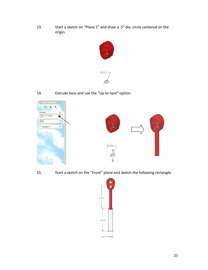
13. Start a sketch on “Plane 1” and draw a .5” dia. circle centered on the origin.
14. Extrude boss and use the “Up to next” option.
15. Start a sketch on the “Front” plane and sketch the following rectangle.

34
16. Extrude boss using the mid-plane option and .750 thick with 7° draft.
17. Using the fillet tool select the following edges and put a .125” radius on them.
35
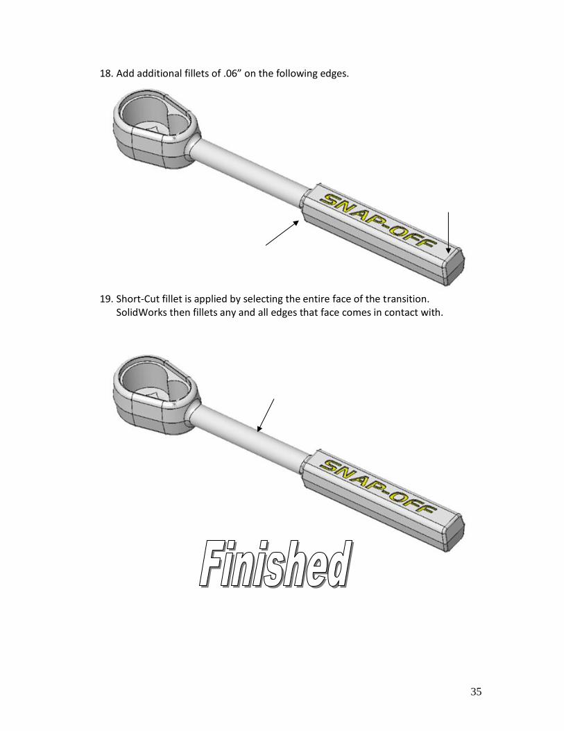
18. Add additional fillets of .06” on the following edges.
19. Short-Cut fillet is applied by selecting the entire face of the transition.
SolidWorks then fillets any and all edges that face comes in contact with.
36
37
38
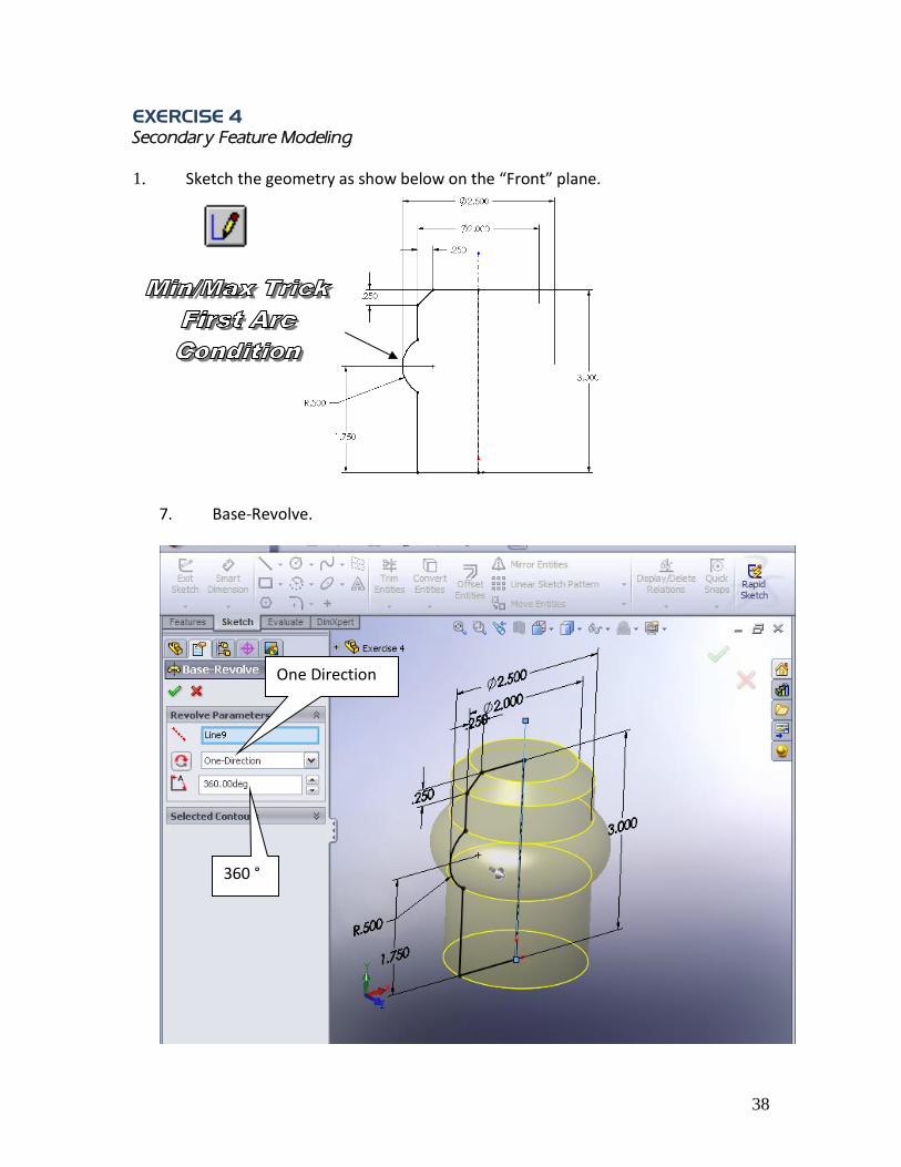
EXERCISE 4
Secondary Feature Modeling
1. Sketch the geometry as show below on the “Front” plane.
7. Base-Revolve.
One Direction
360 °
39
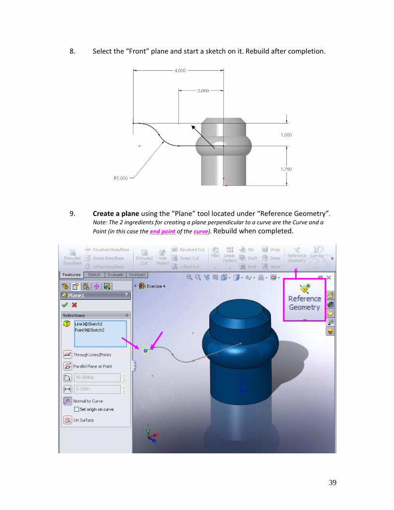
8. Select the “Front” plane and start a sketch on it. Rebuild after completion.
9. Create a plane using the “Plane” tool located under “Reference Geometry”.
Note: The 2 ingredients for creating a plane perpendicular to a curve are the Curve and a
Point (in this case the end point of the curve). Rebuild when completed.

40
10. Select the new plane and sketch the following on it. Rebuild.
11. Select the Sweep Icon. Then select the Path and Profile.
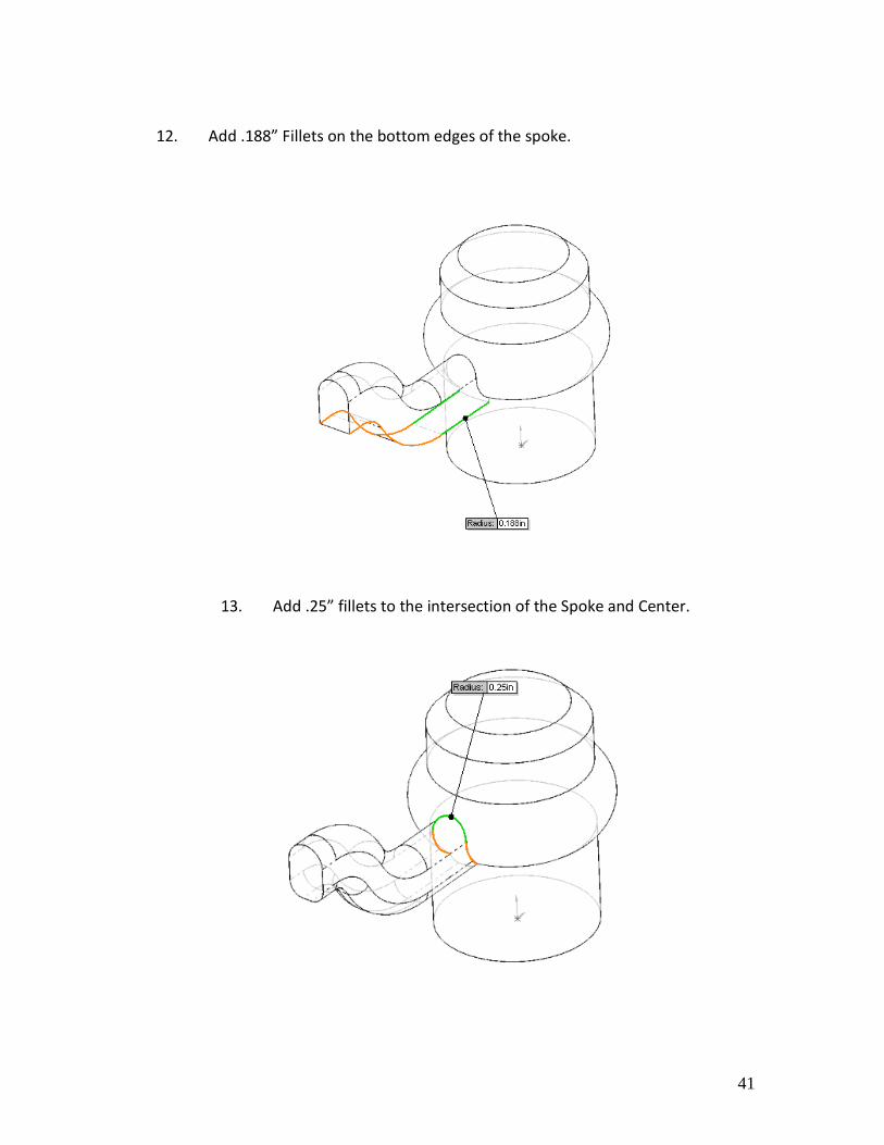
41
12. Add .188” Fillets on the bottom edges of the spoke.
13. Add .25” fillets to the intersection of the Spoke and Center.

42
14. Creating the Circular Pattern/Array: Go to View/and Check on Temporary Axis. Note: This is not necessary in SolidWorks 2008 as new functionality allows you to select
the edge of the cylinder as the pattern axis.
15. Select the Circular Pattern Icon. Then select the Axis or the cylinder edge located at the center and the Spoke. Enter 3 for the number of spokes. Note:
be sure to select the fillets as well, or they will not show up on the instances.

43
11. Select the “Front” plane and start a sketch on it. Draw the following and don’t forget the Centerline.
16. Select the Boss-Revolve Icon, and revolve 360 “One-Direction”.
44
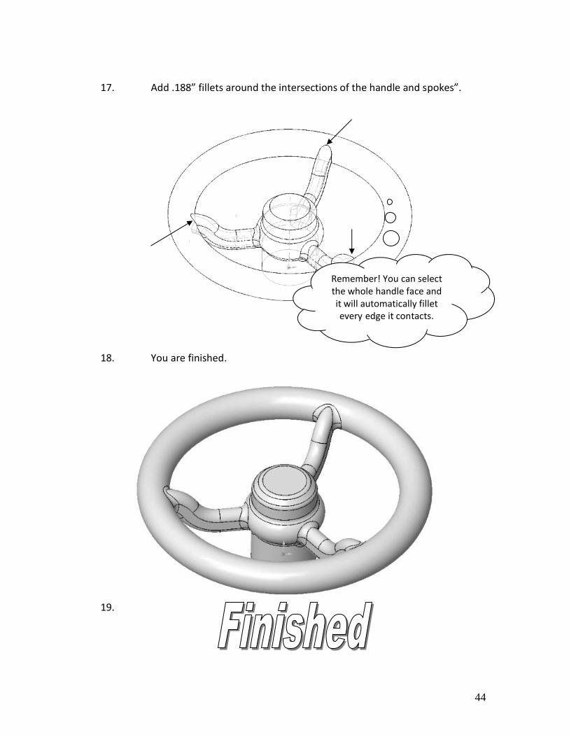
17. Add .188” fillets around the intersections of the handle and spokes”.
18. You are finished.
19.
Remember! You can select the whole handle face and it will automatically fillet every edge it contacts.
45
46

47
EXERCISE 5
Bottom-Up Assembly Creation
1. Go to “File/New and select the Assembly Template”.
2. Assemblies Toolbar.
48
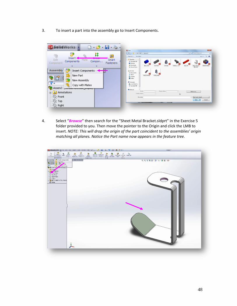
3. To insert a part into the assembly go to Insert Components.
4. Select “Browse” then search for the “Sheet Metal Bracket.sldprt” in the Exercise 5
folder provided to you. Then move the pointer to the Origin and click the LMB to insert. NOTE: This will drop the origin of the part coincident to the assemblies’ origin matching all planes. Notice the Part name now appears in the feature tree.
49
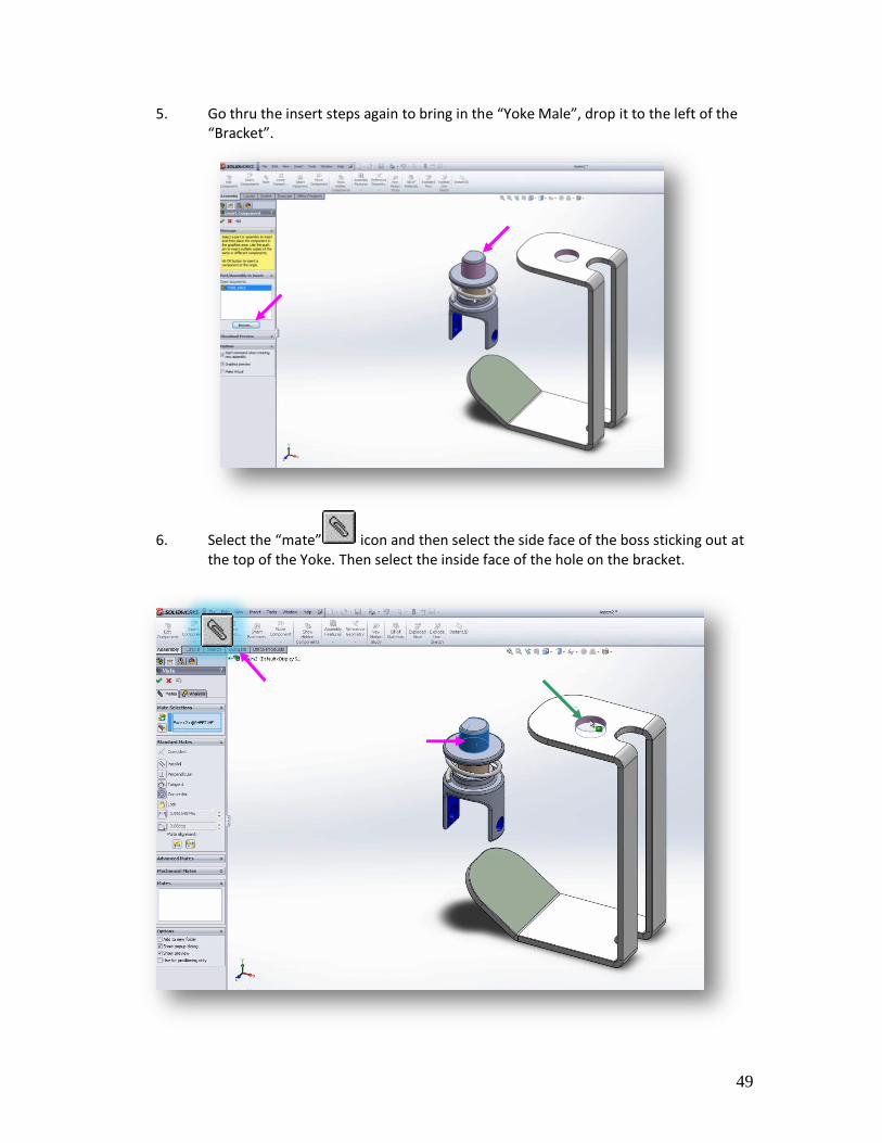
5. Go thru the insert steps again to bring in the “Yoke Male”, drop it to the left of the “Bracket”.
6. Select the “mate” icon and then select the side face of the boss sticking out at the top of the Yoke. Then select the inside face of the hole on the bracket.
50
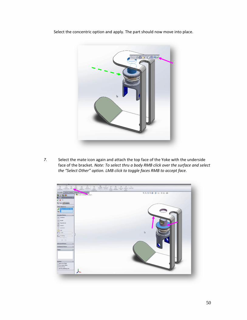
Select the concentric option and apply. The part should now move into place.
7. Select the mate icon again and attach the top face of the Yoke with the underside face of the bracket. Note: To select thru a body RMB click over the surface and select the “Select Other” option. LMB click to toggle faces RMB to accept face.
51
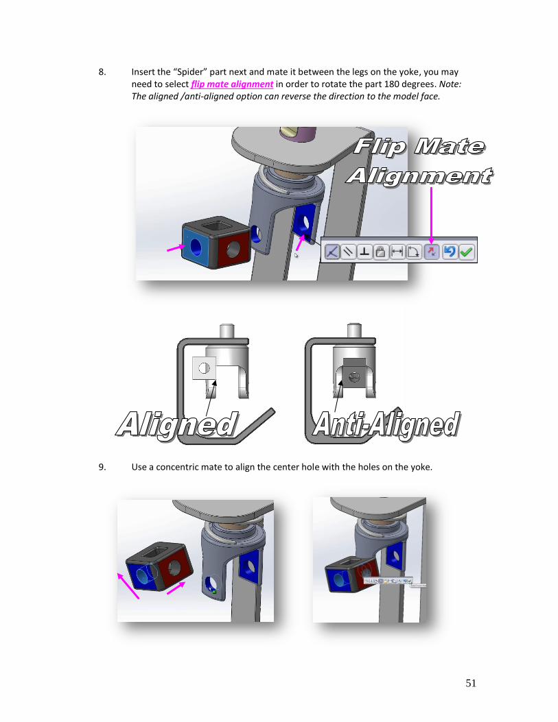
8. Insert the “Spider” part next and mate it between the legs on the yoke, you may need to select flip mate alignment in order to rotate the part 180 degrees. Note: The aligned /anti-aligned option can reverse the direction to the model face.
9. Use a concentric mate to align the center hole with the holes on the yoke.

52
10. Attach the remainder of the components.
11. Dynamic Assembly Motion: After completion you should be able to use the Move
Component icon to dynamically rotate the assembly.

53
55
56

57
EXERCISE 6
Fundamental 2D Drawing Creation
1. Open the “Exercise 6” part file.
2. View Layout/Drawing Toolbar.
58
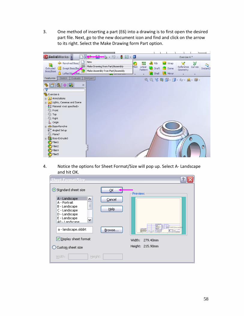
3. One method of inserting a part (E6) into a drawing is to first open the desired part file. Next, go to the new document icon and find and click on the arrow to its right. Select the Make Drawing form Part option.
4. Notice the options for Sheet Format/Size will pop up. Select A- Landscape
and hit OK.
59
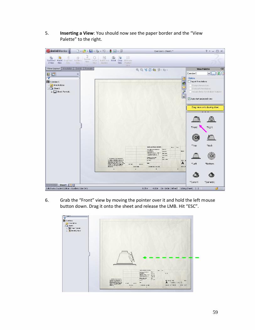
5. Inserting a View: You should now see the paper border and the “View Palette” to the right.
6. Grab the “Front” view by moving the pointer over it and hold the left mouse
button down. Drag it onto the sheet and release the LMB. Hit “ESC”.
60
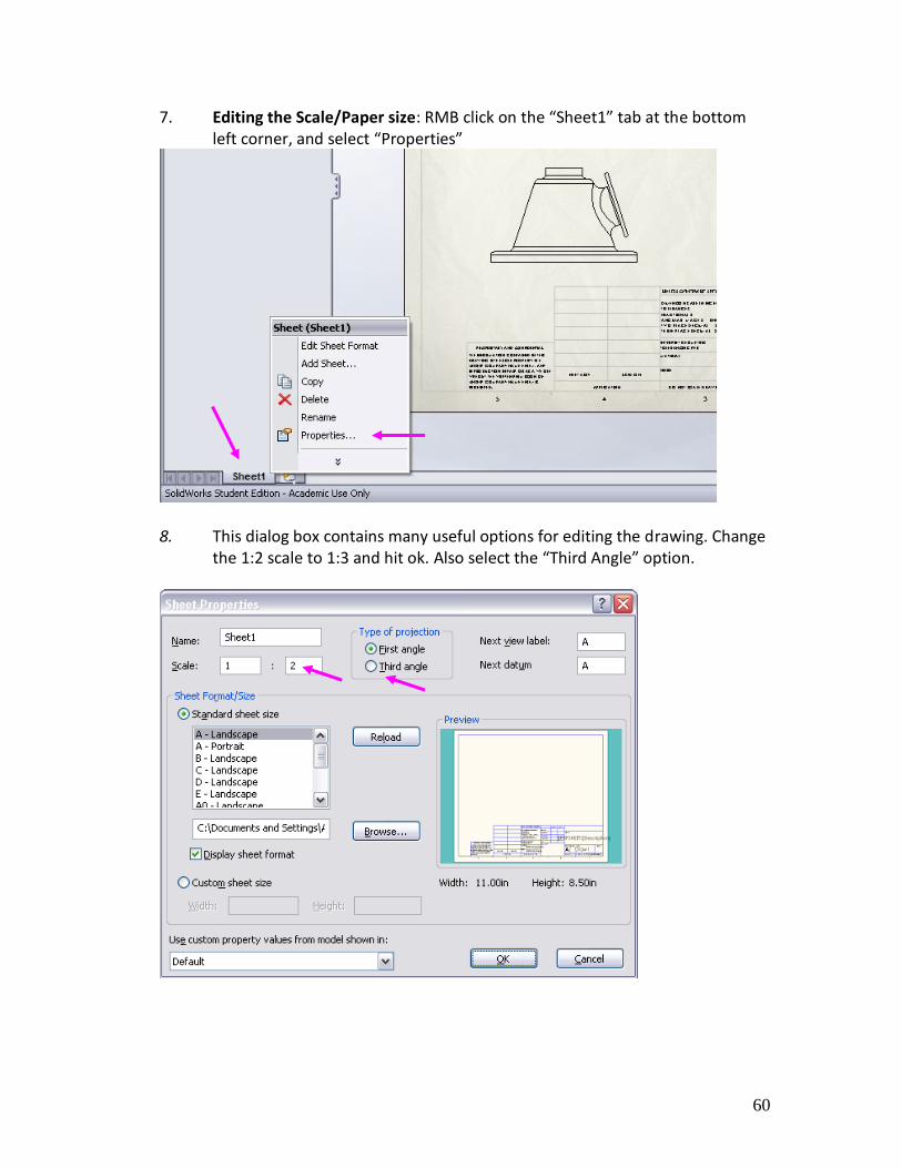
7. Editing the Scale/Paper size: RMB click on the “Sheet1” tab at the bottom left corner, and select “Properties”
8. This dialog box contains many useful options for editing the drawing. Change
the 1:2 scale to 1:3 and hit ok. Also select the “Third Angle” option.
61
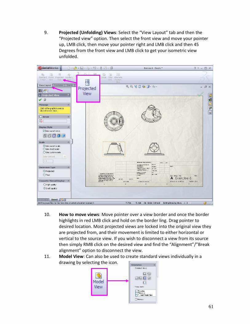
9. Projected (Unfolding) Views: Select the “View Layout” tab and then the “Projected view” option. Then select the front view and move your pointer up, LMB click, then move your pointer right and LMB click and then 45 Degrees from the front view and LMB click to get your isometric view unfolded.
10. How to move views: Move pointer over a view border and once the border highlights in red LMB click and hold on the border ling. Drag pointer to desired location. Most projected views are locked into the original view they are projected from, and their movement is limited to either horizontal or vertical to the source view. If you wish to disconnect a view from its source then simply RMB click on the desired view and find the “Alignment”/”Break alignment” option to disconnect the view.
11. Model View: Can also be used to create standard views individually in a drawing by selecting the icon.
62
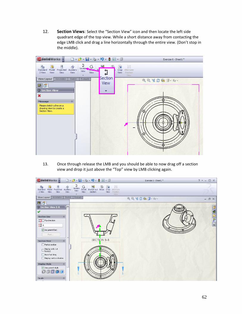
12. Section Views: Select the “Section View” icon and then locate the left side quadrant edge of the top view. While a short distance away from contacting the edge LMB click and drag a line horizontally through the entire view. (Don’t stop in the middle).
13. Once through release the LMB and you should be able to now drag off a section view and drop it just above the “Top” view by LMB clicking again.

63
14. Detail Views: Select the “Detail View” icon. The circle tool is automatically activated so then you can draw a circle surrounding the region you wish to create a detail view from.
15. Move the view to the desired location and LMB click to release/drop it. Note: the view scale can be changed by simply double clicking on the “scale” text and typing in a new value, and the position and diameter of the circle can be changed dynamically by LMB clicking and dragging its center or diameter.
64
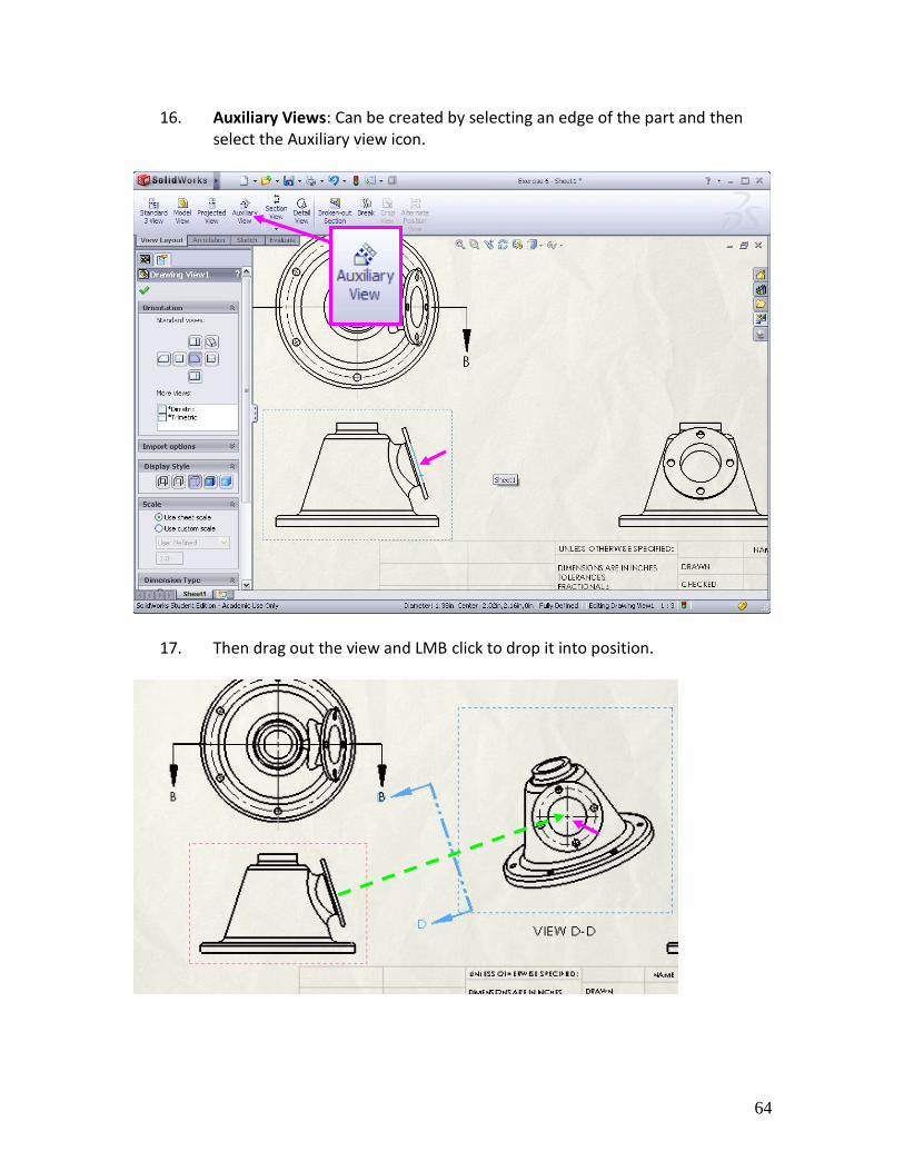
16. Auxiliary Views: Can be created by selecting an edge of the part and then select the Auxiliary view icon.
17. Then drag out the view and LMB click to drop it into position.
65
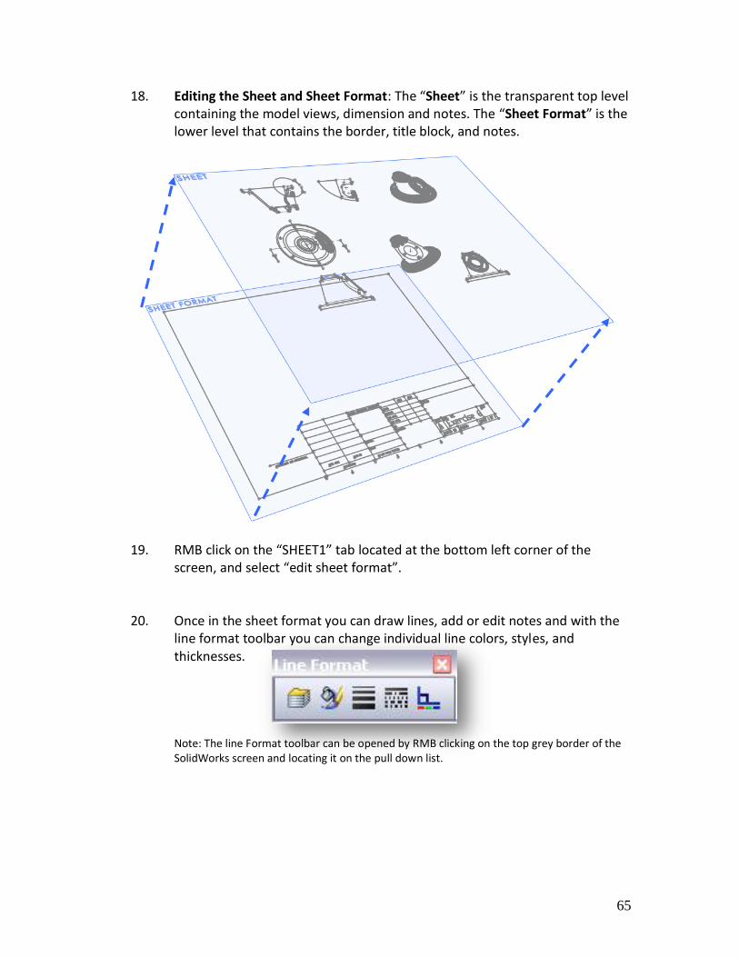
18. Editing the Sheet and Sheet Format: The “Sheet” is the transparent top level containing the model views, dimension and notes. The “Sheet Format” is the lower level that contains the border, title block, and notes.
19. RMB click on the “SHEET1” tab located at the bottom left corner of the
screen, and select “edit sheet format”.
20. Once in the sheet format you can draw lines, add or edit notes and with the line format toolbar you can change individual line colors, styles, and thicknesses.
Note: The line Format toolbar can be opened by RMB clicking on the top grey border of the SolidWorks screen and locating it on the pull down list.
66
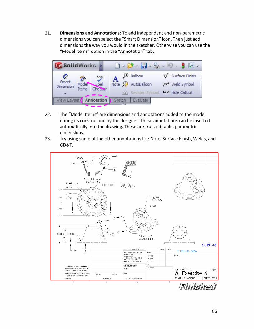
21. Dimensions and Annotations: To add independent and non-parametric dimensions you can select the “Smart Dimension” icon. Then just add dimensions the way you would in the sketcher. Otherwise you can use the “Model Items” option in the “Annotation” tab.
22. The “Model Items” are dimensions and annotations added to the model during its construction by the designer. These annotations can be inserted automatically into the drawing. These are true, editable, parametric dimensions.
23. Try using some of the other annotations like Note, Surface Finish, Welds, and GD&T.
67
68
EXERCISE 7
Projected Curves and Sweeping
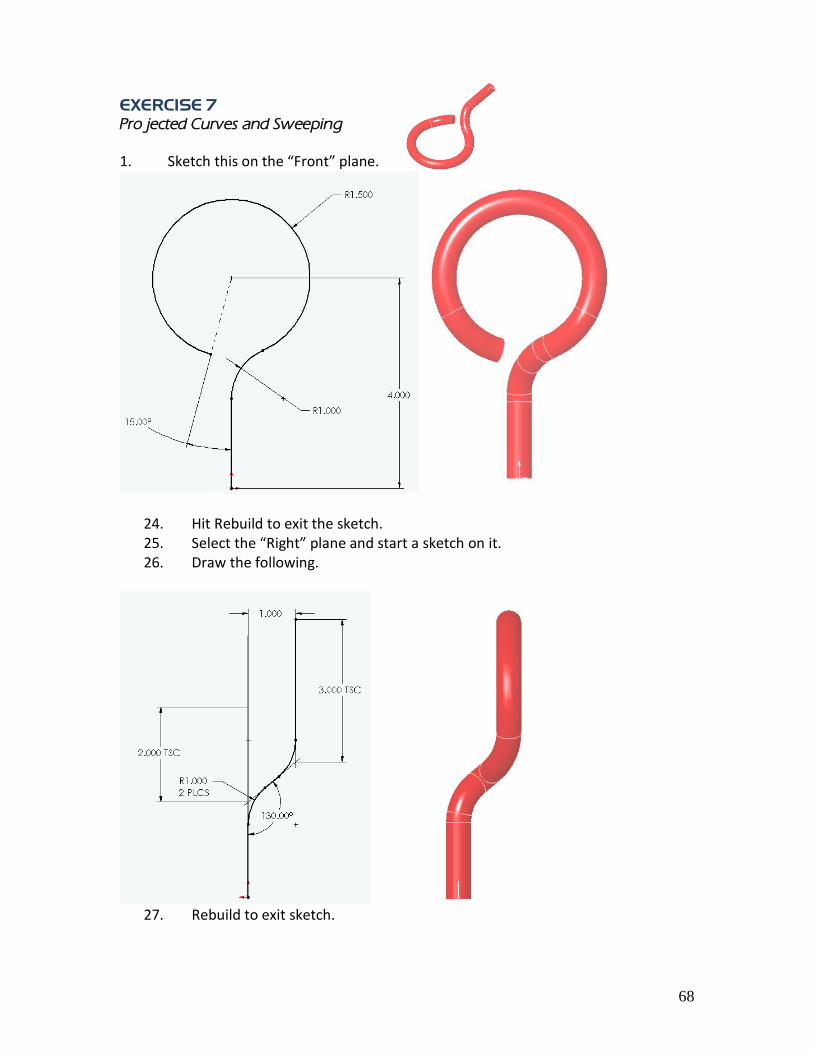
1. Sketch this on the “Front” plane.
24. Hit Rebuild to exit the sketch. 25. Select the “Right” plane and start a sketch on it. 26. Draw the following.
27. Rebuild to exit sketch.
69
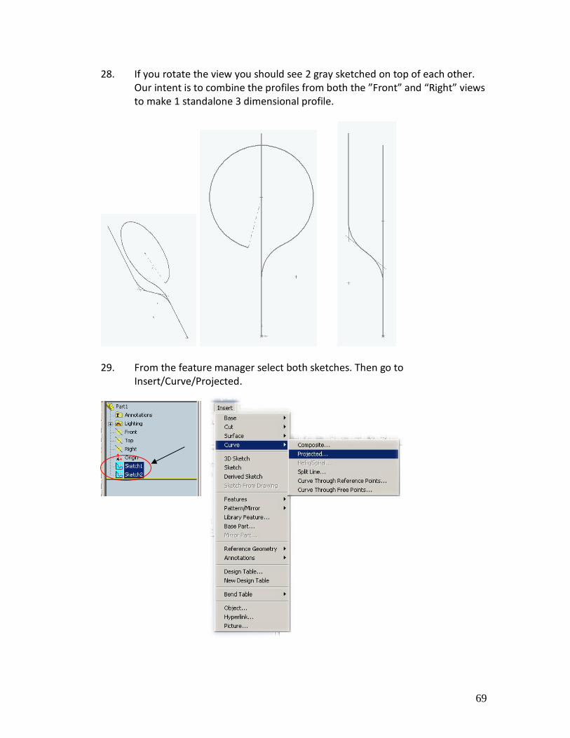
28. If you rotate the view you should see 2 gray sketched on top of each other. Our intent is to combine the profiles from both the ”Front” and “Right” views to make 1 standalone 3 dimensional profile.
29. From the feature manager select both sketches. Then go to
Insert/Curve/Projected.
70
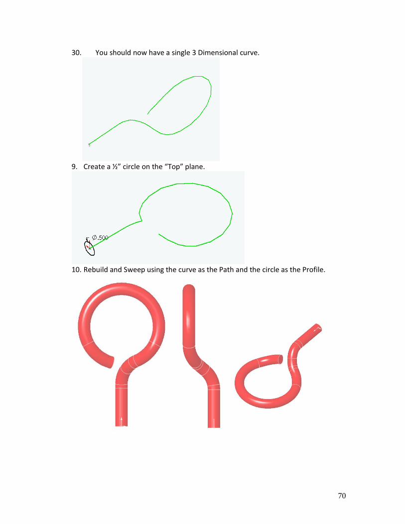
30. You should now have a single 3 Dimensional curve.
9. Create a ½” circle on the “Top” plane.
10. Rebuild and Sweep using the curve as the Path and the circle as the Profile.

71
12. Start a sketch on the “Front” plane. Draw the following.
13. Rebuild to exit the sketch. Select the end face and start a sketch. While the end
face is still highlighted green select the Convert Entities icon. Rebuild.
Convert Entities
Creates one or more curves in a sketch by projecting an edge, loop,
face, curve, or external sketch contour, set of edges, or set of sketch
curves onto the sketch plane.
72
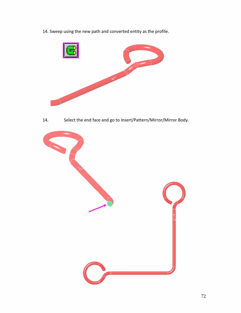
14. Sweep using the new path and converted entity as the profile.
14. Select the end face and go to Insert/Pattern/Mirror/Mirror Body.

73
Now using the tools you have learned over the past 5 weeks finish the remainder of the model.
Hints to complete the model…
Boss Revolve “Two Directions”

74
The completed part; check to see if your feature tree looks the same as this one.

75
76
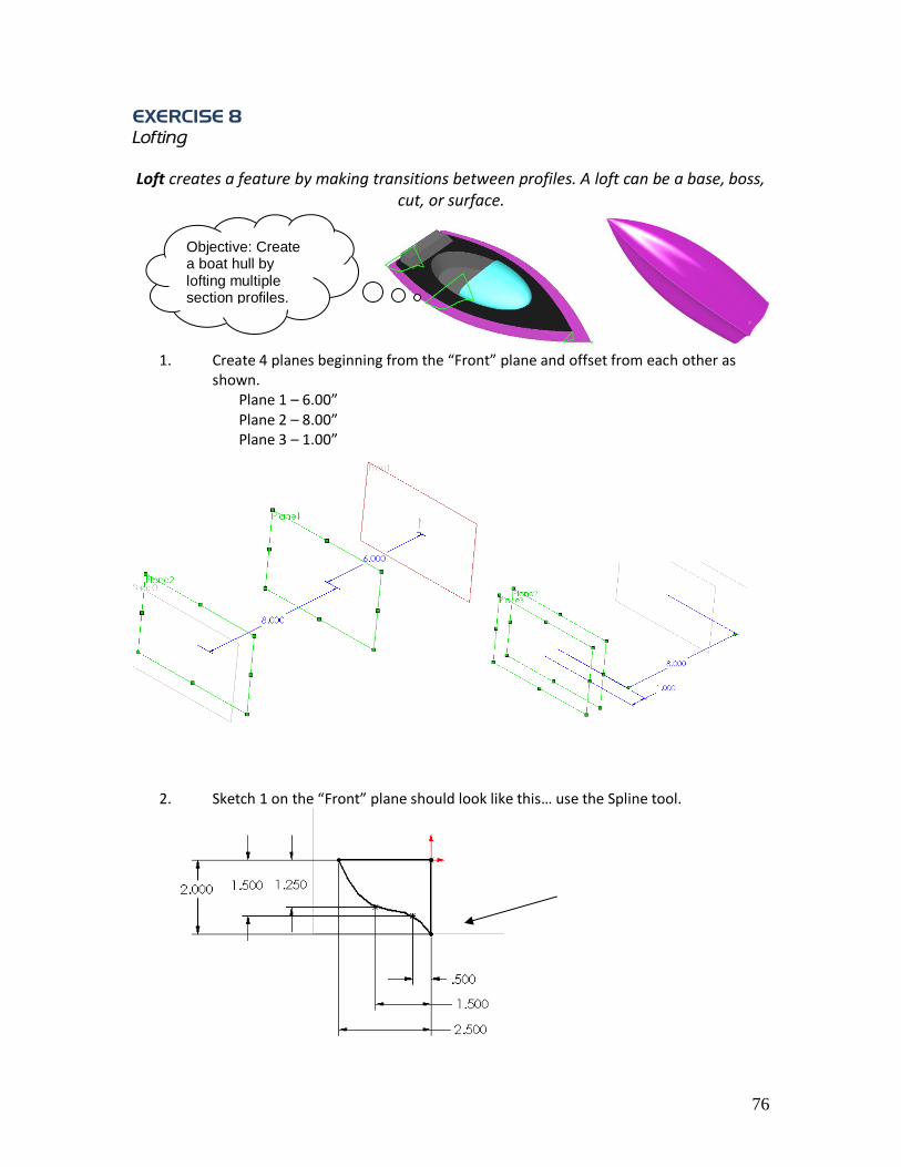
EXERCISE 8
Lofting
Loft creates a feature by making transitions between profiles. A loft can be a base, boss, cut, or surface.
1. Create 4 planes beginning from the “Front” plane and offset from each other as
shown. Plane 1 – 6.00” Plane 2 – 8.00” Plane 3 – 1.00”
2. Sketch 1 on the “Front” plane should look like this… use the Spline tool.
Objective: Create a boat hull by lofting multiple section profiles.
77
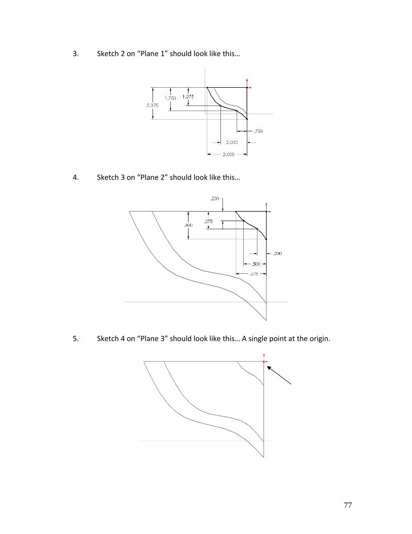
3. Sketch 2 on “Plane 1” should look like this…
4. Sketch 3 on “Plane 2” should look like this…
5. Sketch 4 on “Plane 3” should look like this… A single point at the origin.

78
6. If you rotate the view it should appear like this…
7. Select the Loft icon and begin to select the top left corner of each profile.
79
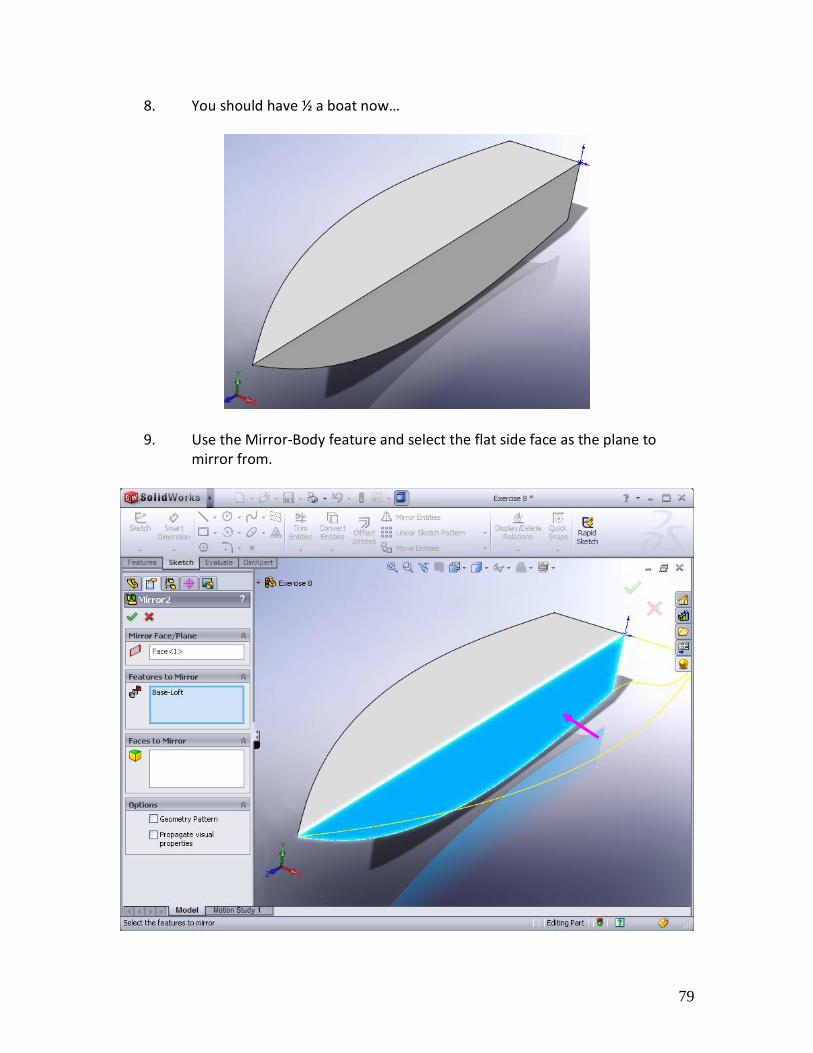
8. You should have ½ a boat now…
9. Use the Mirror-Body feature and select the flat side face as the plane to mirror from.
80
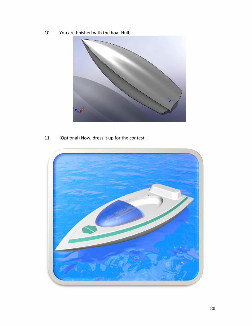
10. You are finished with the boat Hull.
11. (Optional) Now, dress it up for the contest…

81
82
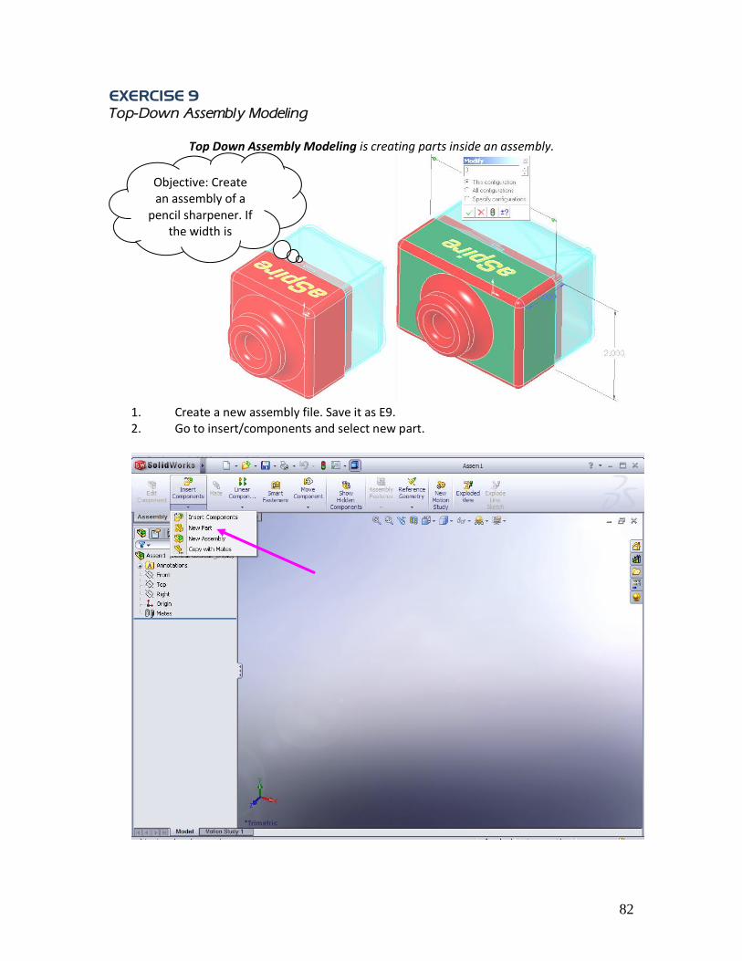
EXERCISE 9
Top-Down Assembly Modeling
Top Down Assembly Modeling is creating parts inside an assembly.
1. Create a new assembly file. Save it as E9. 2. Go to insert/components and select new part.
Objective: Create an assembly of a
pencil sharpener. If the width is
changed all parts
must update.

83
3. Save it as E9 Front and drop it on the “Front” plane. Create the following part from
the drawing.
84
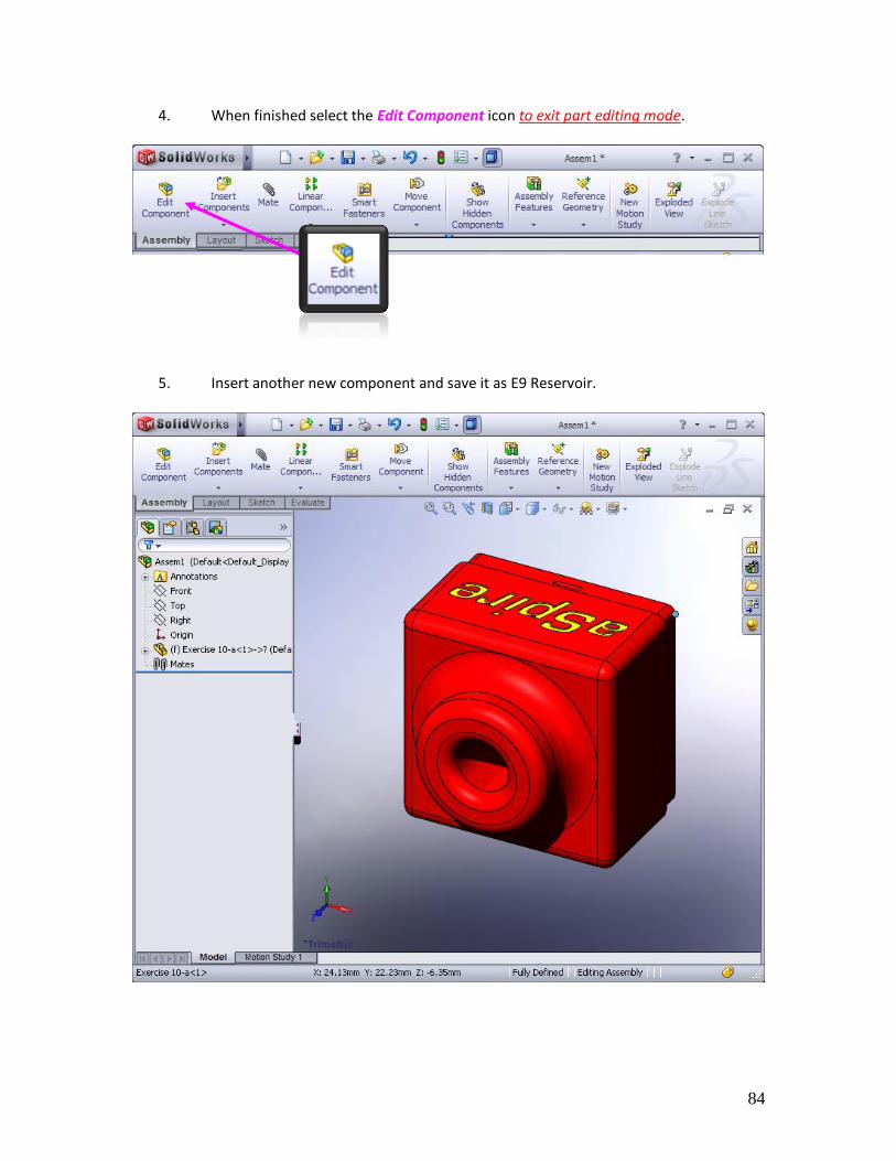
4. When finished select the Edit Component icon to exit part editing mode.
5. Insert another new component and save it as E9 Reservoir.
85
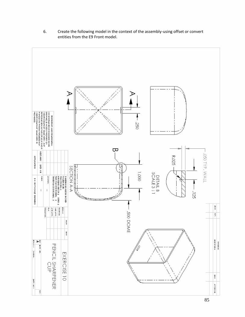
6. Create the following model in the context of the assembly-using offset or convert entities from the E9 Front model.

86

87
EXERCISE 10
Assembly Editing
This exercise will include both Bottom-Up and Top-Down Assembly Modeling.
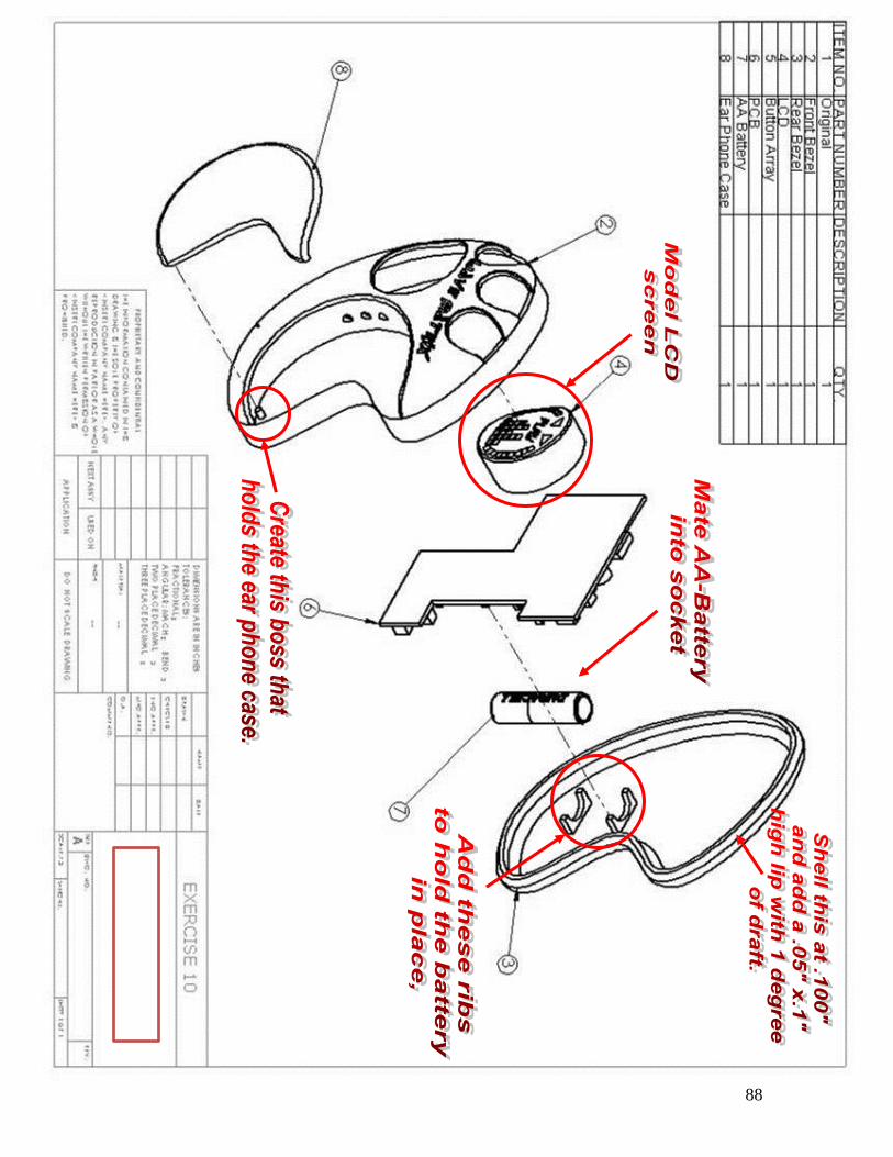
7. Open the parasolid file called MP3 and modify according to the instructions
noted on the drawing provided. You will have to mate the Battery part file.
Objective: To update the MP3 Assembly with the
changes requested by the boss as noted on the
drawing.
88
89
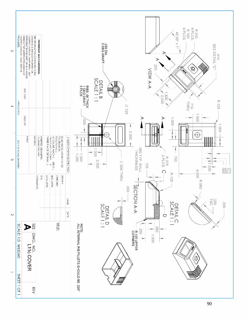
90
91
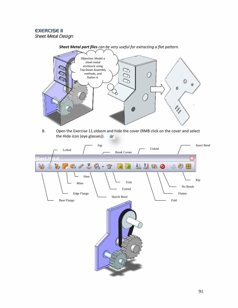
EXERCISE 11
Sheet Metal Design
Sheet Metal part files can be very useful for extracting a flat pattern.
8. Open the Exercise 11.sldasm and hide the cover (RMB click on the cover and select
the Hide icon (eye glasses)).
Objective: Model a sheet metal
enclosure using Top-Down Assembly
methods, and flatten it.
Insert Bend
Flatten
Rip
Base Flange
Miter
Fold
Unfold
No Bends Extend
Trim
Hem
Break Corner
Jog
Sketch Bend Edge Flange
Lofted

92
9. Insert a new part into the assembly; drop it on the “Front” plane of the assembly. Name it “E11 Cover” (This will be the enclosure) then select the front outside face. Convert Entities.
10. Extrude up to vertex.

93
11. Once open the assembly should look like this. Right Mouse click on the surface of
the enclosure and select “open E12.sldprt”.
12. Go to an isometric view and “ctrl” select the four faces as shown.
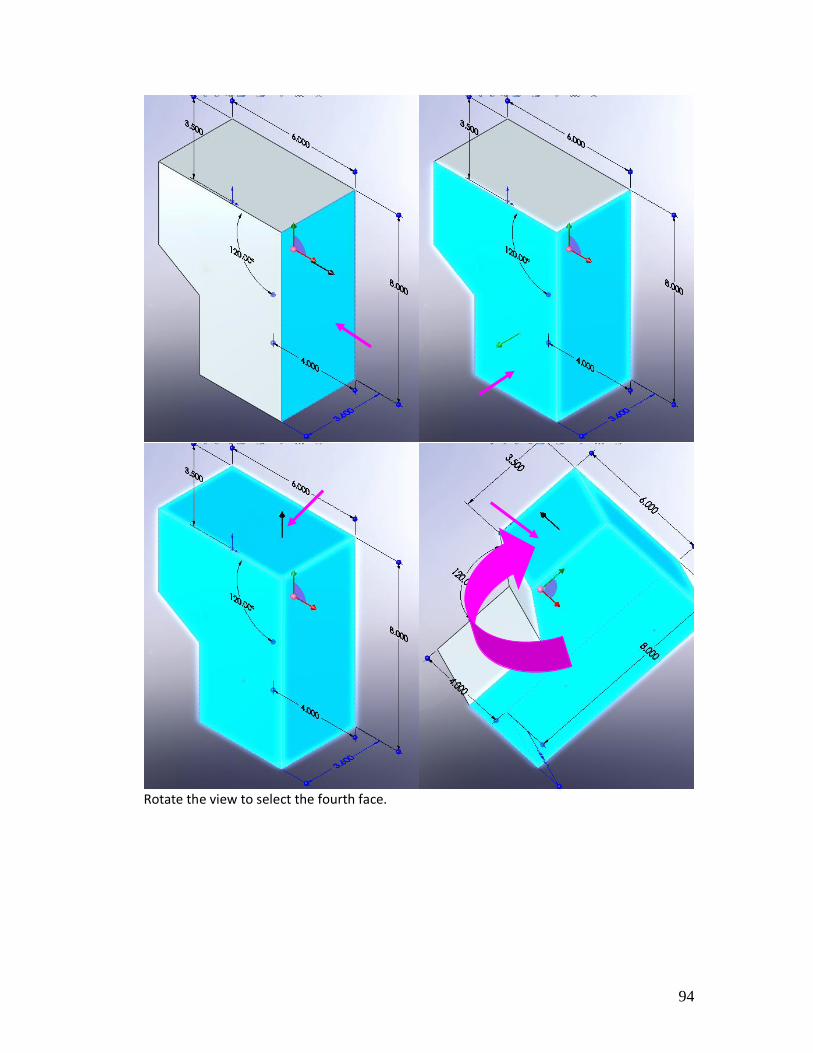
94
Rotate the view to select the fourth face.
95
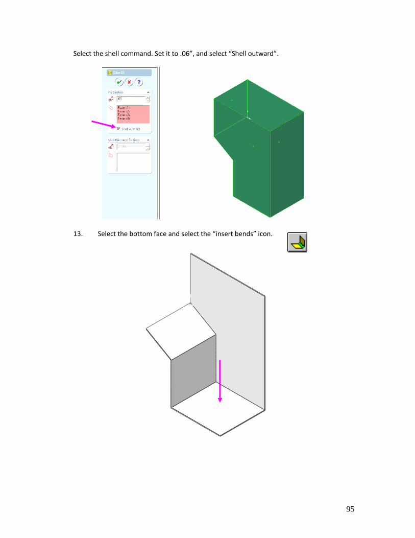
Select the shell command. Set it to .06”, and select “Shell outward”.
13. Select the bottom face and select the “insert bends” icon.
96
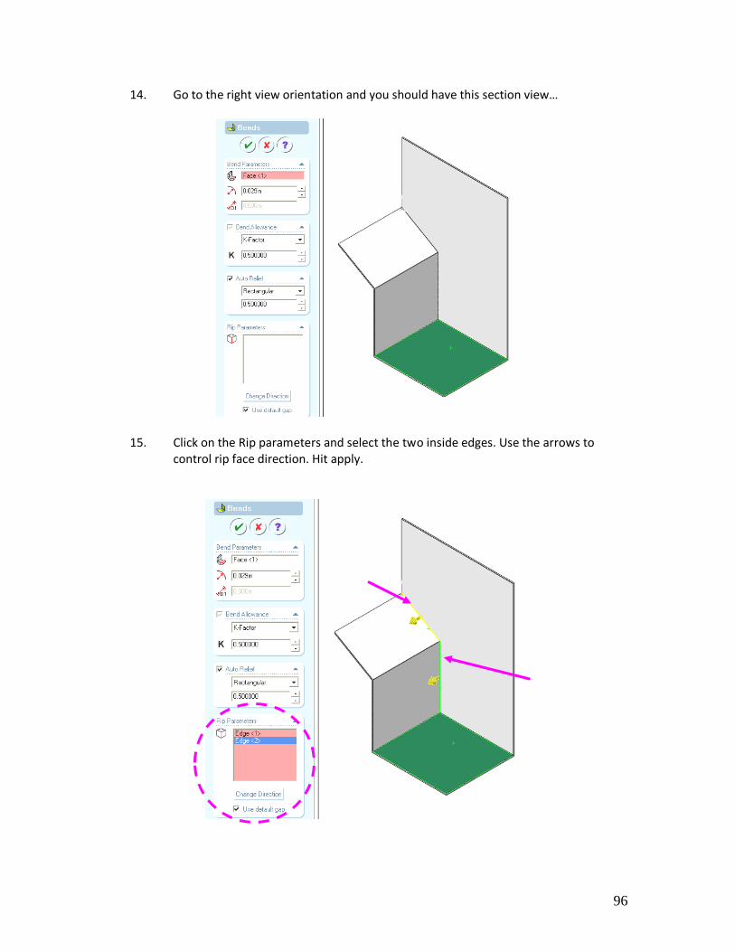
14. Go to the right view orientation and you should have this section view…
15. Click on the Rip parameters and select the two inside edges. Use the arrows to control rip face direction. Hit apply.
97
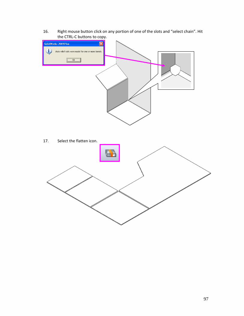
16. Right mouse button click on any portion of one of the slots and “select chain”. Hit the CTRL-C buttons to copy.
17. Select the flatten icon.

98
12. Return to the assembly.
13. Add holes and additional features.
14. The enclosure is now completed. Recreate the attached drawing for your Lab.
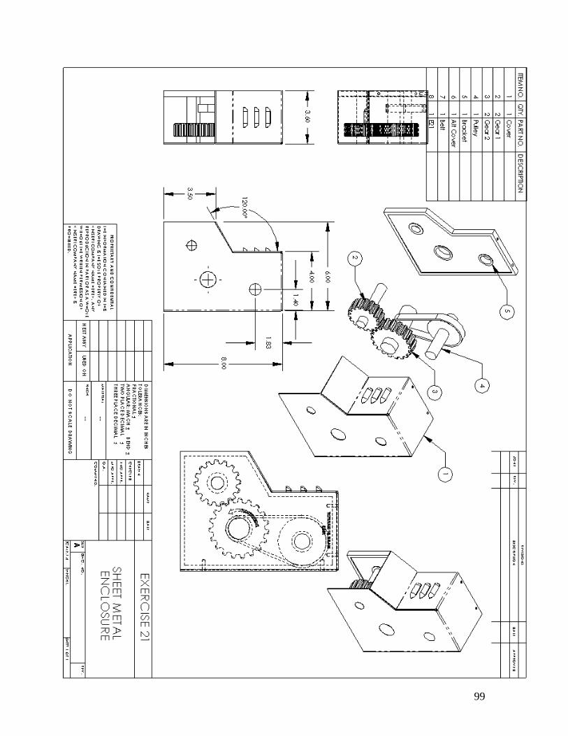
99
100
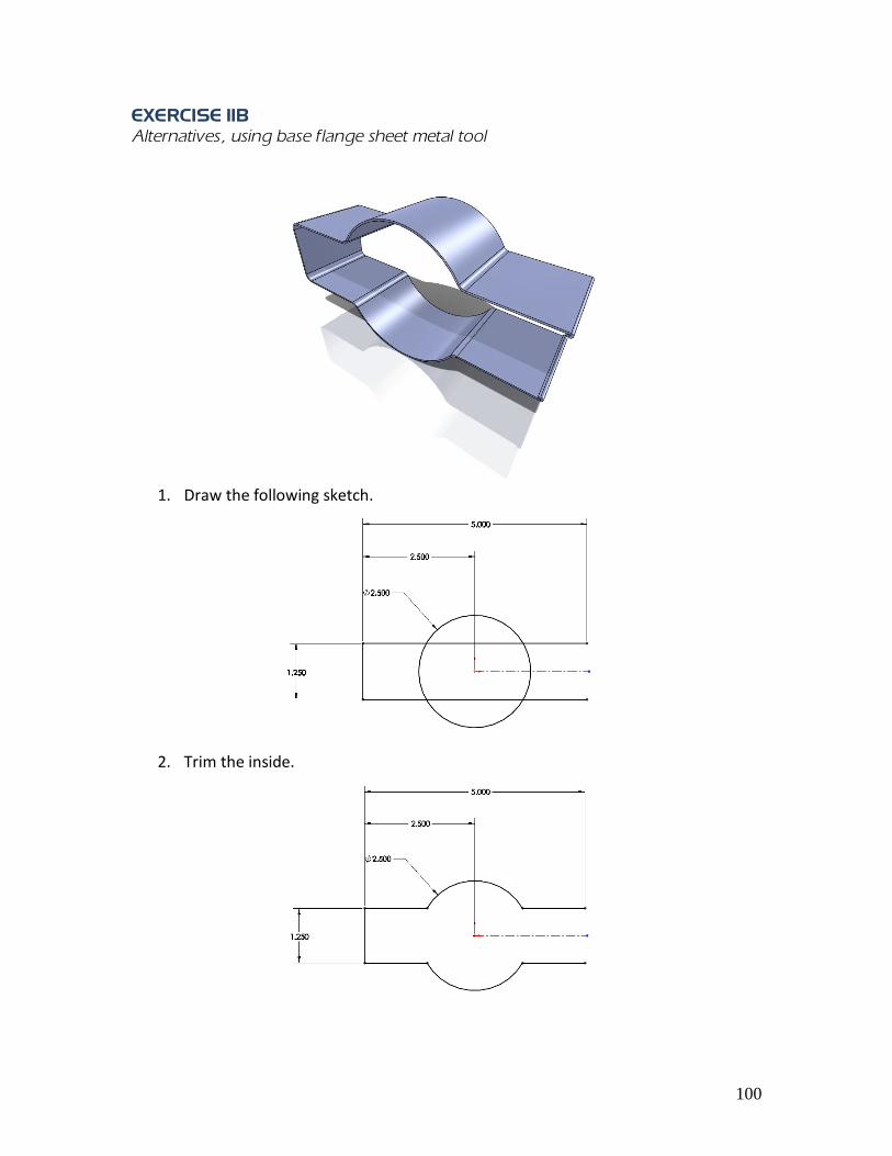
EXERCISE 11B
Alternatives, using base flange sheet metal tool
1. Draw the following sketch.
2. Trim the inside.
101
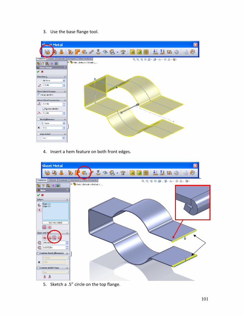
3. Use the base flange tool.
4. Insert a hem feature on both front edges.
5. Sketch a .5” circle on the top flange.

102
6. Extrude cut through-all.
103
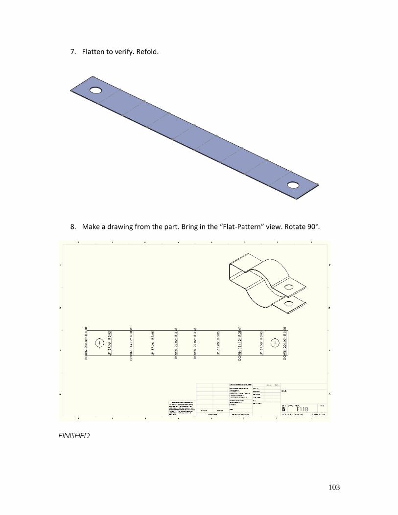
7. Flatten to verify. Refold.
8. Make a drawing from the part. Bring in the “Flat-Pattern” view. Rotate 90°.
FINISHED
104
105