Embed Size (px)
Citation preview

University Of Jordan
Department Of Mechatronics Engineering
AUTOMATIC SOLAR TRACKING SYSTEM Project Planning & Construction Report
Version <2.0>
<04/11/2014> Prepared By:
Ehab Al Hamayel 0105758
Saif Maaita 0091352
2
AUTOMATIC SOLAR TRACKING SYSTEM
Contents 1. OVERVIEW ……………………………………………………………………………………………………………………………………………………3
1.1 General overview about the project …………………………………..…………………………………………………………………3
1. 2 Project planning and construction stages ………………………..…………………………………………………………………3
2. Project analysis and challenges ………………………………………………………………………………………………………………3
2.1 Challenges …………………………………………………………………………………………………………………………………………………3
2.2 Project analysis …………………………………………………………………………………………………………………………………………3
2.3 Systems Inputs/Outputs ……………………………………………………………………………………………………………………………4
3. General Sketch Of the system ……………………………………………………………………………………………………………………4
4. System’s Block Diagram & Operation sequence……………………………………………………………………………………5
5. Circuit Diagram and Component. ……………………………………………………………………………………………………………6
5.2 Electronic Components …………………………………………………………………………………………………………………………….11
6.Detailed Drawing of system’s mechanical component ……………………………………….…………………………….12
7.System Flowchart……………………………………….…………………………………………………………………………………………………..15
3
AUTOMATIC SOLAR TRACKING SYSTEM
1. OVERVIEW
1.1 General overview about the project
The Project under construction is expected to track the sun position all the daytime in order to deliver
the maximum electrical energy from the PV array panel by keeping the sunray perpendicular to the
panel , the tracker has two linear actuators moving the panel in 2-axis motion horizontally and
vertically . The unit has its own controller which consists of a microcontroller and driving circuits, the
sun illumination intensity is measured with four photo sensors, two on each axis .
1. 2 Project planning and construction stages
This phase will include the necessary project analysis and challenges, and then it will represent a
general sketch of the conceptual design , and it will followed by the system’s block diagram ,
sequence of operation, Circuit design, Mechanical design, and finally the system’s flowchart.
2. Project analysis and challenges
2.1 Challenges
- Designing a tracker that is capable of tracking the sun position in 4 directions.
- insure the system will track the sun position accurately.
- The system must avoid undetermined random motion as a result of a poor sun light.
2.2 Project analysis
The system must start from a predetermined initial position at the beginning of daytime, then
measure the difference between the two photo sensors output on each axis, send actuating signal to
the linear actuator motors to move the PV panel until differential signal between the sensors become
small and around zero, then the microcontroller will be putted in idler mode for 20 minutes and
repeat the sequence tell sunset without exceeding the motion range ,then back to its initial position
and go into idler mode till the daybreak next day.
The system is special type of closed-loop systems since it has a feedback to measure the sun light
intensity, the main difference between it and conventional SISO closed-loop systems that it will not
compare the feedback with a specific set point.
4
AUTOMATIC SOLAR TRACKING SYSTEM
The proposed controller in this project is a Role-based control algorithm which will give us a
satisfactory result.
2.3 Systems Inputs/Outputs
a) System’s Inputs
1- four photo sensors donated by (LDRR,LDRL,LDRT,LDB).
2- four digital signals from four limit switches donated by (LSR,LSL,LSUP,LSDN).
b) System’s Outputs
1- 4 Digital signals to control the motor driving IC donated by (M1CW, M1CCW,M2CW,M2CCW).
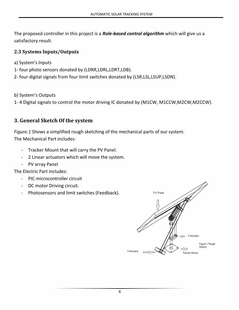
3. General Sketch Of the system
Figure.1 Shows a simplified rough sketching of the mechanical parts of our system.
The Mechanical Part includes:
- Tracker Mount that will carry the PV Panel.
- 2 Linear actuators which will move the system.
- PV array Panel
The Electric Part includes:
- PIC microcontroller circuit
- DC motor Driving circuit.
- Photosensors and limit switches (Feedback).

5
AUTOMATIC SOLAR TRACKING SYSTEM
4. System’s Block Diagram & Operation sequence
The Block Diagram of the automatic solar tracking system is shown in Figure.2
Starting from a predetermined initial position at the beginning of daytime, microcontroller reads the
difference between the two photo sensors output on each axis, send actuating signal to the linear
actuator motors to move the PV panel until differential signal between the sensors become small and
around zero, then the microcontroller will be putted in idler mode for 20 minutes and repeat the
sequence tell sunset without exceeding the motion range ,then back to its initial position and go into
idler mode till the daybreak next day, PV panel DC output is converted to AC via conventional Power
inverter in order to deliver the output power to the national grid .
PIC microcontroller is to be used , the status and generated power will be displayed on 2x16 LCD.
6
AUTOMATIC SOLAR TRACKING SYSTEM
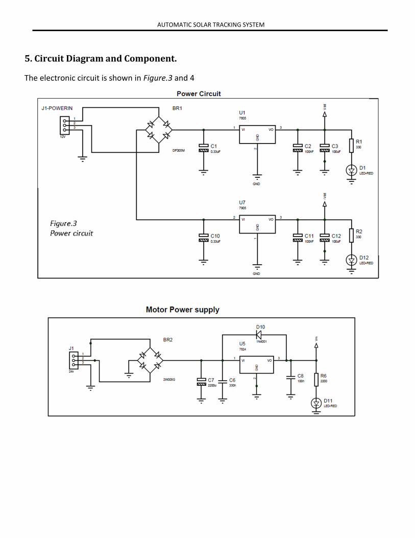
5. Circuit Diagram and Component.
The electronic circuit is shown in Figure.3 and 4

7
AUTOMATIC SOLAR TRACKING SYSTEM
8
AUTOMATIC SOLAR TRACKING SYSTEM
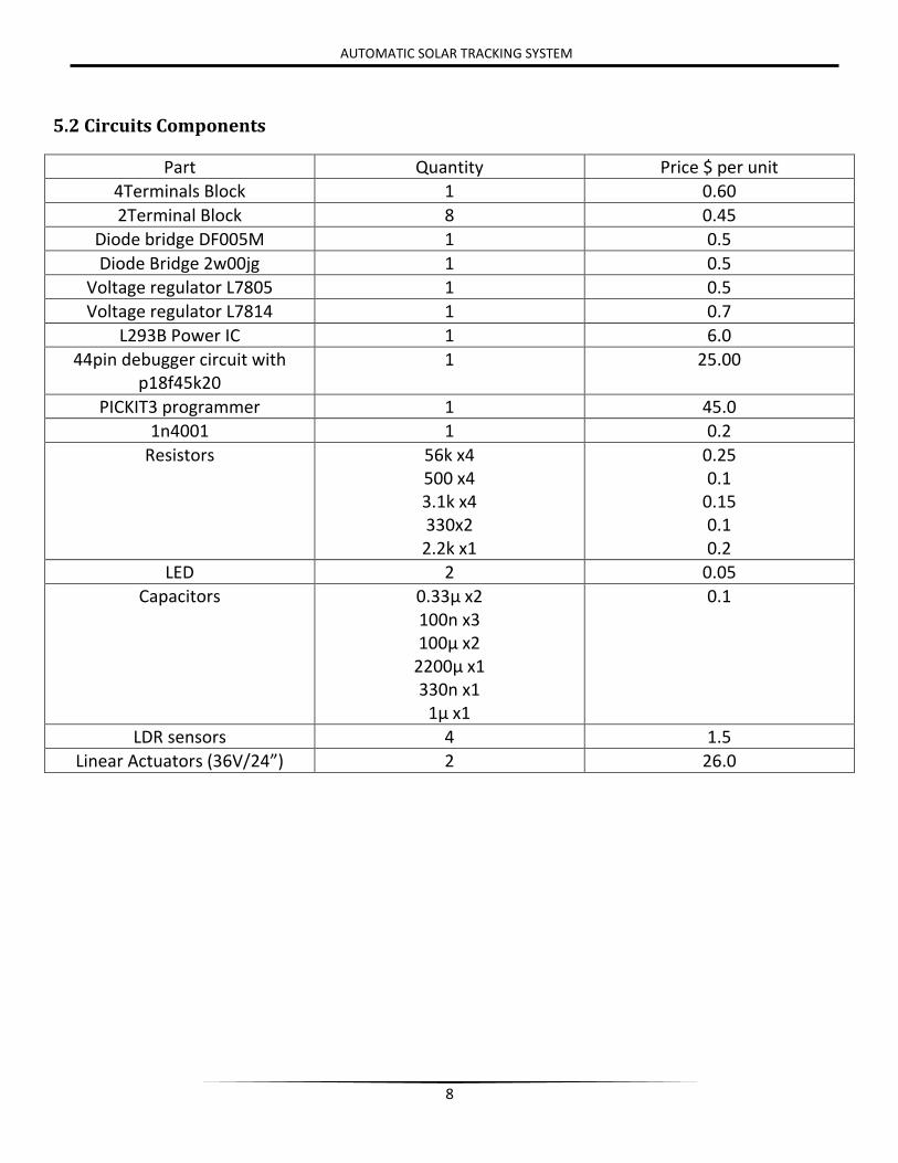
5.2 Circuits Components
Part Quantity Price $ per unit
4Terminals Block 1 0.60
2Terminal Block 8 0.45
Diode bridge DF005M 1 0.5
Diode Bridge 2w00jg 1 0.5
Voltage regulator L7805 1 0.5
Voltage regulator L7814 1 0.7
L293B Power IC 1 6.0
44pin debugger circuit with p18f45k20
1 25.00
PICKIT3 programmer 1 45.0
1n4001 1 0.2
Resistors 56k x4 500 x4 3.1k x4 330x2 2.2k x1
0.25 0.1
0.15 0.1 0.2
LED 2 0.05
Capacitors 0.33µ x2 100n x3 100µ x2
2200µ x1 330n x1
1µ x1
0.1
LDR sensors 4 1.5
Linear Actuators (36V/24”) 2 26.0
9
AUTOMATIC SOLAR TRACKING SYSTEM
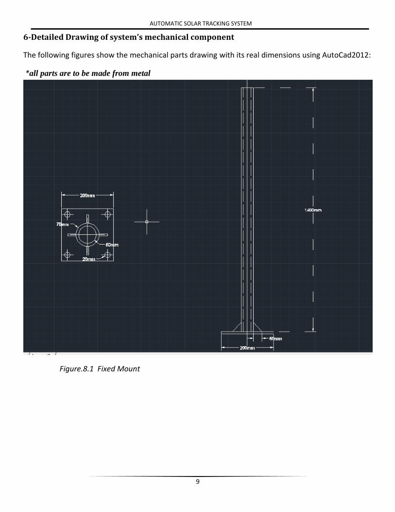
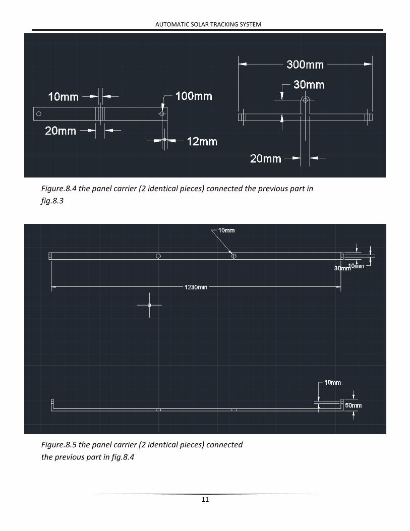
6-Detailed Drawing of system’s mechanical component
The following figures show the mechanical parts drawing with its real dimensions using AutoCad2012:
*all parts are to be made from metal
Figure.8.1 Fixed Mount
10
AUTOMATIC SOLAR TRACKING SYSTEM
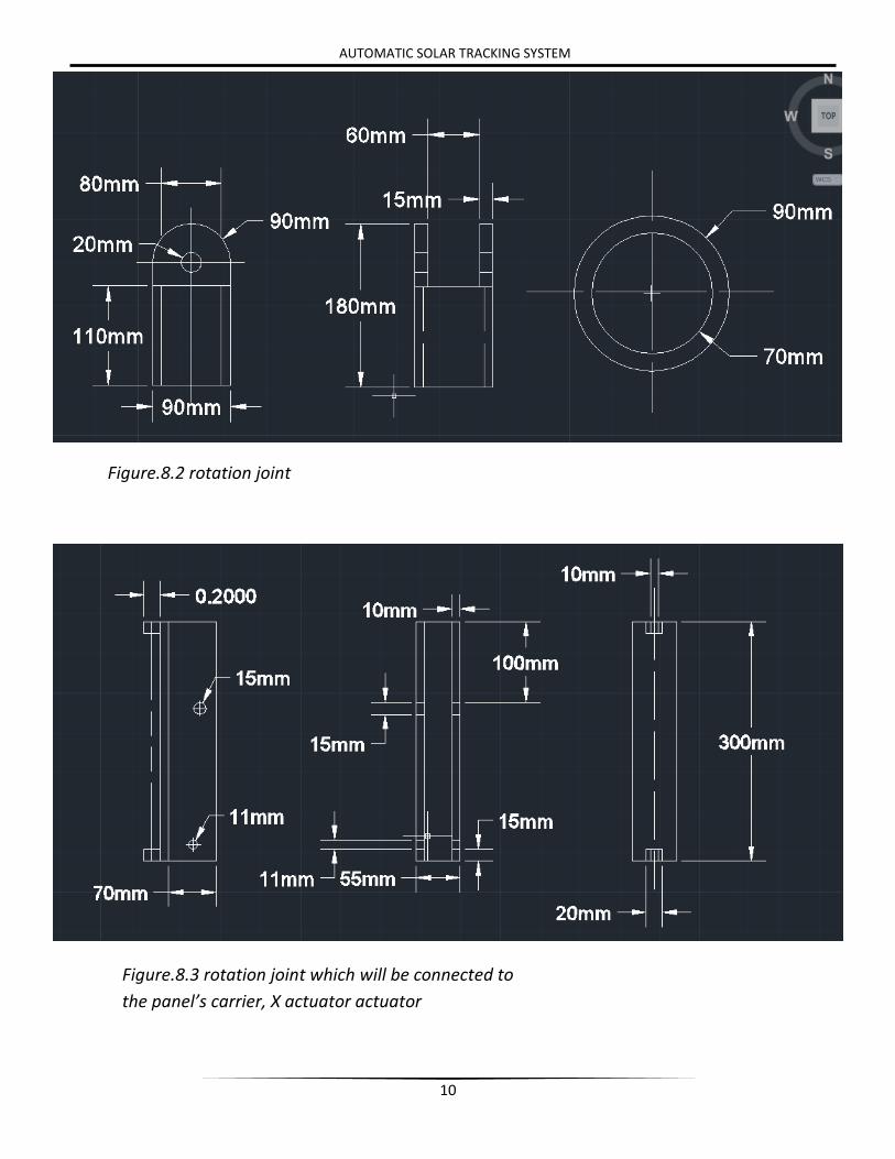
Figure.8.2 rotation joint
Figure.8.3 rotation joint which will be connected to
the panel’s carrier, X actuator actuator
11
AUTOMATIC SOLAR TRACKING SYSTEM
Figure.8.4 the panel carrier (2 identical pieces) connected the previous part in
fig.8.3
Figure.8.5 the panel carrier (2 identical pieces) connected
the previous part in fig.8.4
12
AUTOMATIC SOLAR TRACKING SYSTEM
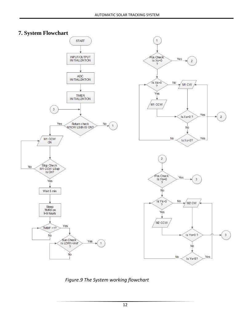
7. System Flowchart
Figure.9 The System working flowchart