Embed Size (px)
Citation preview

Isotropic Finishing for Surface Integrity and Part Performance
The webinar will start at 2:00pm (EST)
Brought to you by SME Membership
August 19, 2015

SME Membership Pg.2
• 1 hour webinar: 45 min + 15 min Q&A. • Attendee phones will be muted during the webinar.
• During the presentation, you can log your questions in the Q&A window
of the WebEx screen.
• The presentation will be recorded. A web link to the recording will be emailed to attendees within 24 hrs by SME.
• If you have any difficulties, please email [email protected]
Webinar Housekeeping Rules

Today’s Webinar
Isotropic Finishing for Surface Integrity
and Part Performance
SME Speaker: Dave Davidson SME Advisor: Machining/Material Removal Technical Community
SME Speaker: Jack R. Clark, President Surface Analytics, LLC, Fort Collins, CO Faculty Affiliate: Colorado State University

SME Membership Pg.4
What are Isotropic Surfaces?
Why are they important? .

SME Membership Pg.5
Isotropic Finishing Bearings (IFB)
2-D and 3-D surface views
SME Membership Pg.6
Isotropic Finishing: Definition
• In contrast to machined or ground surfaces Isotropic surfaces are non-directional or random in character.
• They do not exhibit the surface pattern of parallel lines, grooves or notches common to all machining methods
• This is a desirable surface characteristic functionally as the overall amount of surface available for bearing loads can be increased dramatically and machining notches which provide potential failure related crack propagation points are attenuated substantially.

SME Membership Pg.7
Centrifugal Isotropic Finishing (CIF)
– How it works…
• Rotating Turret
• Counter-rotating barrels
• High Internal G-Forces
• Rapid media turnover and slide zone

SME Membership Pg.8
CBF Advantages:
• Very high speed processing
• Quick change over capability
• Different parts can be processed simultaneously in different chambers
• Compartmentalization or fixturing possible
• Very refined surfaces possible especially in sequential processing

SME Membership Pg.9
CBF Isotropic Finishing - Bearings
• Bearings require substantial processing to produce low-micro-inch surfaces needed for optimal load bearing capability.
SME Membership Pg.10
Hands-Free Surface Finishing
of 3-D metal printed parts
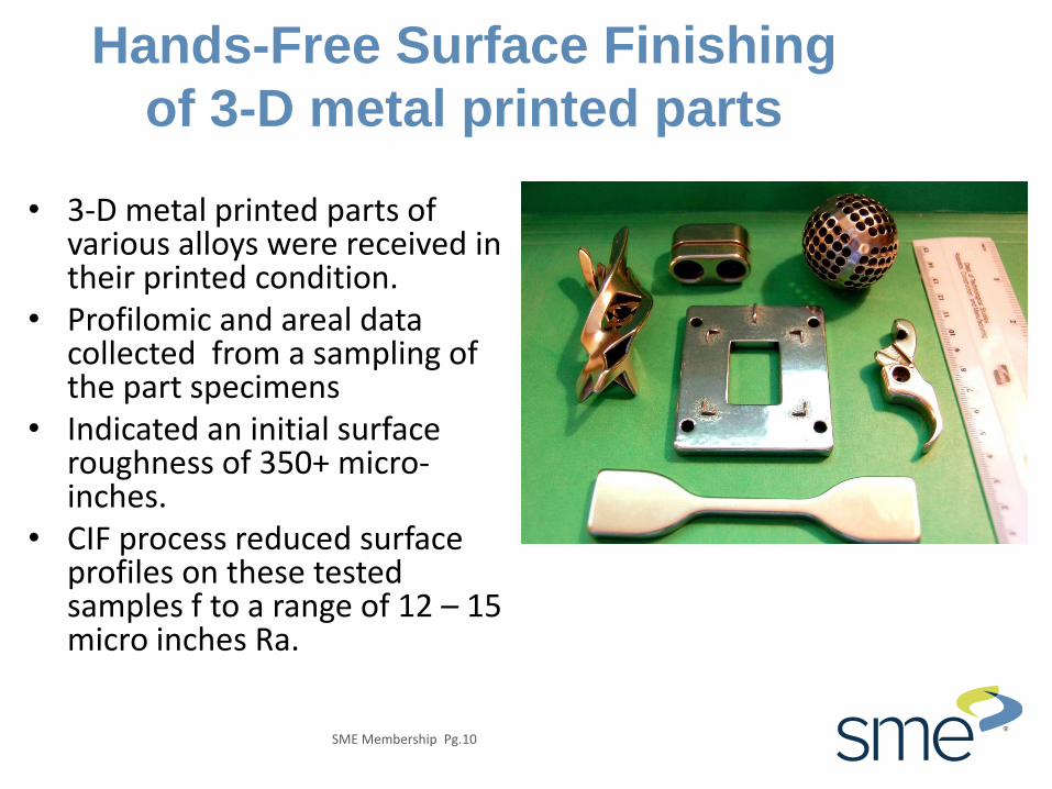
• 3-D metal printed parts of various alloys were received in their printed condition.
• Profilomic and areal data collected from a sampling of the part specimens
• Indicated an initial surface roughness of 350+ micro-inches.
• CIF process reduced surface profiles on these tested samples f to a range of 12 – 15 micro inches Ra.

SME Membership Pg.11
Centrifugal Isotropic Finishing of
Laser cut stainless steel
Stainless Steel, laser cut using nitrogen as the shielding gas.

SME Membership Pg.12
Extreme Finishing
• Flame-cut foundry steel
castings, with as-cast and flame-cut surfaces.
• Demonstration experiment to validate surface profile reduction on extremely rough surfaces.

SME Membership Pg.13
Heat-treat scale removal, edge-contour,
burnishing automotive parts
• These heat-treated automotive stampings require cleaning and edge contour on exterior and interior edges.
• CIF high-intensity finishing processes with smaller media used as the process was able to achieve specifications for radiusing the inside edges of the part that conventional processing could not.
SME Membership Pg.14
Small Part Finishing: Metal
Injection Molding
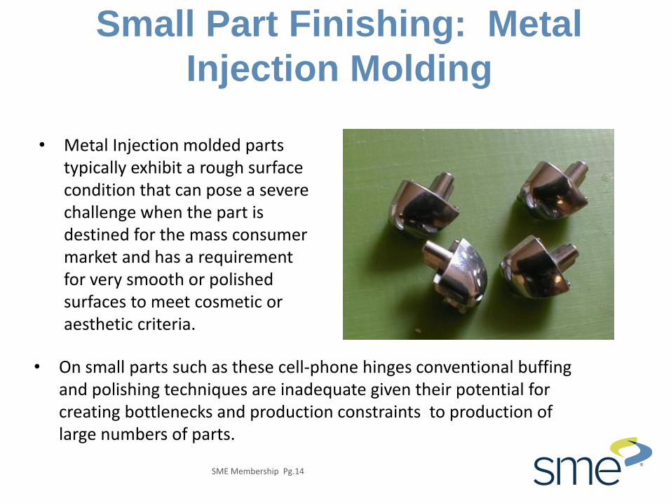
• Metal Injection molded parts typically exhibit a rough surface condition that can pose a severe challenge when the part is destined for the mass consumer market and has a requirement for very smooth or polished surfaces to meet cosmetic or aesthetic criteria.
• On small parts such as these cell-phone hinges conventional buffing and polishing techniques are inadequate given their potential for creating bottlenecks and production constraints to production of large numbers of parts.
SME Membership Pg.15
CBF Isotropic Finishing
Dental Applications
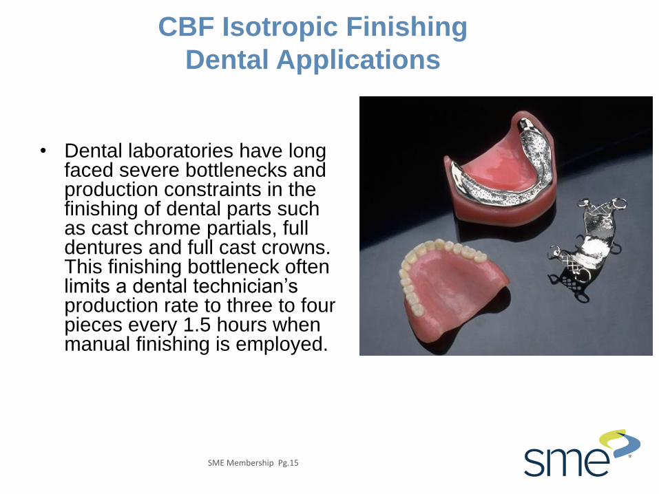
• Dental laboratories have long faced severe bottlenecks and production constraints in the finishing of dental parts such as cast chrome partials, full dentures and full cast crowns. This finishing bottleneck often limits a dental technician’s production rate to three to four pieces every 1.5 hours when manual finishing is employed.

SME Membership Pg.16
CBF Isotropic Finishing – Carbide Tooling
• Two process tracks have been developed for improving tooling with edge and surface preparation. One process that has been developed utilizes non-abrasive materials to burnish edges and surfaces.
• The other track uses dry process media material in conjunction with polishing abrasives to develop more refined and consistent tooling edges that are more predictable. This type of processing adds service life and improves cutting performance

SME Membership Pg.17
Medical Device Finishing
• In the medical industry, the fine isotropic finish produced by CBF machines is a requirement.
• Processing metal implants in centrifugal finishing machines helps reduce complications within surgeries and procedures.
• Centrifugal machines are also used by companies that produce other medical devices.

SME Membership Pg.18
Isotropic Surface Generation on Roller Bearings –
Before and After, SEM and 3D views compared.
(As ground vs. CBF Finish)
Photos by Jack Clark, Surface Analytics, [email protected] | SME MMR Tech Community
SME Membership Pg.19
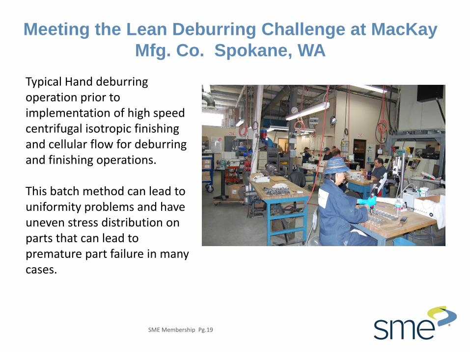
Meeting the Lean Deburring Challenge at MacKay
Mfg. Co. Spokane, WA
Typical Hand deburring operation prior to implementation of high speed centrifugal isotropic finishing and cellular flow for deburring and finishing operations. This batch method can lead to uniformity problems and have uneven stress distribution on parts that can lead to premature part failure in many cases.

SME Membership Pg.20
High speed isotropic finishing in cellular flow environment replaces most hand finishing…

SME Membership Pg.21
Parts can be processed in bulk

SME Membership Pg.22
Parts can be processed in
Compartments with Fixtures

SME Membership Pg.23
High pressure finishing can remove machining or
milling marks for ultra-smooth surfaces

SME Membership Pg.24
Smaller parts with difficult to access
geometries can be finished…

Isotropic vs. Conventional Ground Surfaces
SRa= 1.05 SRz = 19.31 SRpk = 2.50 SRk = 2.38 SRvk=2.42
SRa= 0.435 SRz = 5.65 SRpk = 0.17 SRk = 0.45 SRvk=1.33

SME Membership Pg.26
Diesel Camshaft and Roller Tappet
High Wear Interface

SME Membership Pg.27
Failure!
• When the form and roughness of each component is not compatible, FAILURE is guaranteed!

SME Membership Pg.28
Complex Cam Roller Profile
SME Membership Pg.29
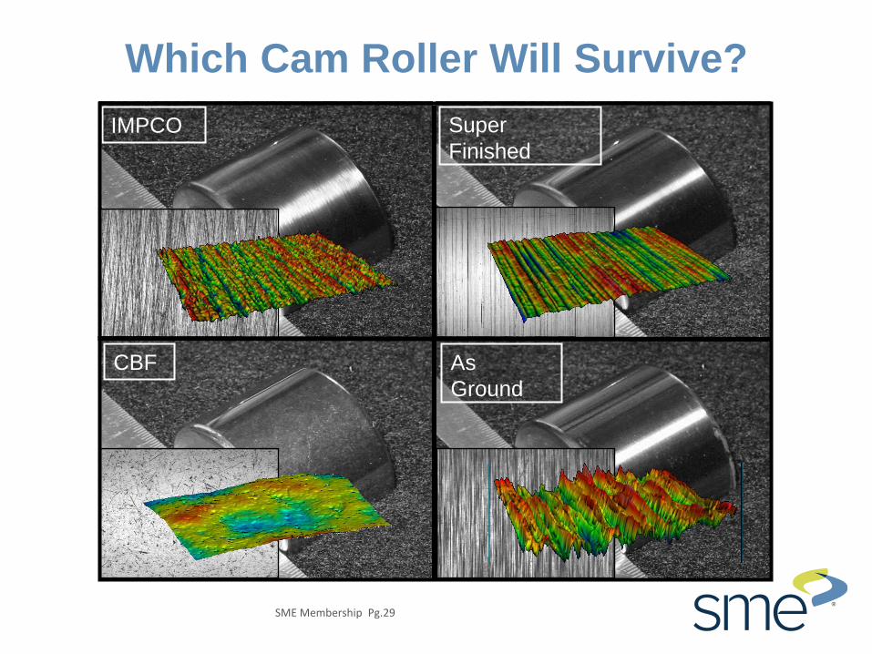
Which Cam Roller Will Survive?
IMPCO
CBF As
Ground
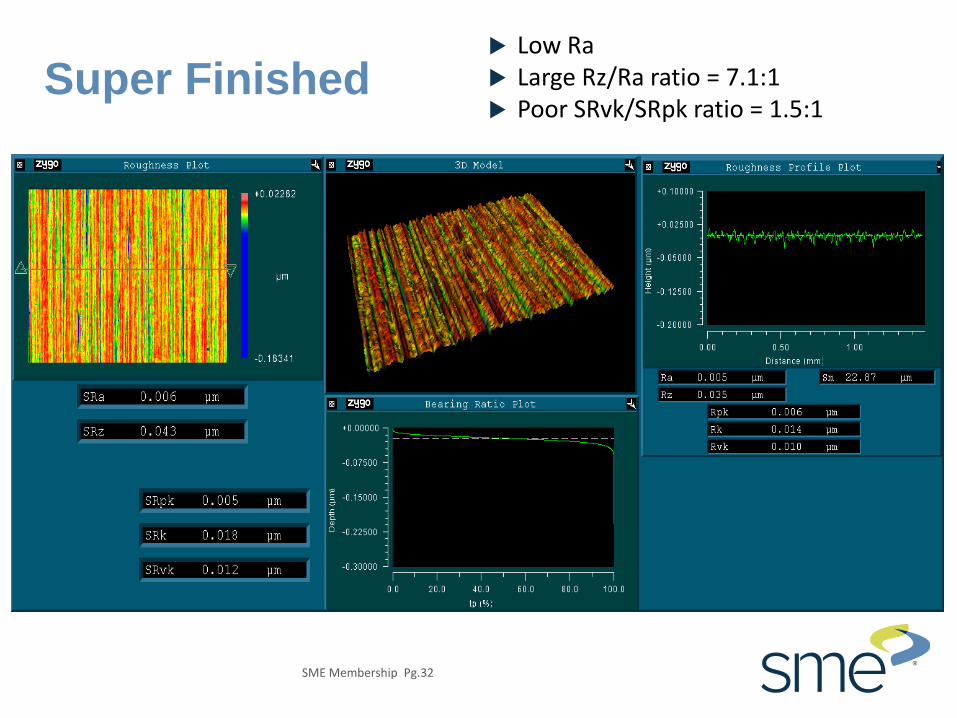
Super
Finished

SME Membership Pg.30
As Ground High Ra Large Rz/Ra ratio = 6.5:1 Poor SRvk/SRpk ratio = 1.9:1

SME Membership Pg.31
Cross Hatch Better Ra Very Large Rz/Ra ratio = 9:1 Better SRvk/SRpk ratio = 2.4:1
SME Membership Pg.32
Super Finished Low Ra Large Rz/Ra ratio = 7.1:1 Poor SRvk/SRpk ratio = 1.5:1

SME Membership Pg.33
CBF Finished Best Ra Best Rz/Ra ratio = 6.1:1 Better SRvk/SRpk ratio = 2.1:1

SME Membership Pg.34
Draw and Iron (D&I) Aluminum
Can Punch and Die • The punch drives a sheet of aluminum through a progressively
smaller and smaller pack of dies to thin the material and form the can.
• If the surface finish of the punch does not retain lubricant and vent air, the newly formed can cannot be “stripped” off the punch damaging the can.
• If the finish on the dies is not such that they produce a “bright looking” can, it will not be marketable.

SME Membership Pg.35
Can Punch
Conventional Grind
Good Ra Excellent SRvk/SRpk ratio = 4.1:1 Unpredictable can release

SME Membership Pg.36
Can Punch
Conventional Grind
• The texture of the grind limits the lubricant flow and restricts air flow to support release.
• The Texture Aspect Ratio (Str) reveals a small included angle that is not good for lubrication distribution.
Even though the roughness and Bearing Ratio are “good”...

SME Membership Pg.37
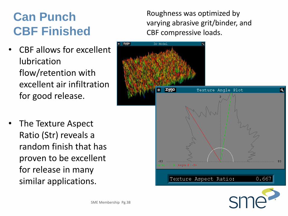
Can Punch
CBF Finished
Good Ra SRvk/SRpk ratio = 1.4:1 Predictable can release
SME Membership Pg.38
Can Punch
CBF Finished
• CBF allows for excellent lubrication flow/retention with excellent air infiltration for good release.
• The Texture Aspect Ratio (Str) reveals a random finish that has proven to be excellent for release in many similar applications.
Roughness was optimized by varying abrasive grit/binder, and CBF compressive loads.

SME Membership Pg.39
Spinal Implant Manufacturing Issues
SME Membership Pg.40
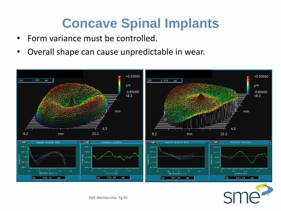
Concave Spinal Implants • Form variance must be controlled.
• Overall shape can cause unpredictable in wear.

SME Membership Pg.41
Convex Spinal Implants • Each step of the forming of the part must be monitored.
• Turing and super finishing artifacts remain after final polishing.

SME Membership Pg.42
Wear Analysis
• Wear on Convex Implant.
• Original spherical form will be removed for wear analysis.

Convex
Concave
New Part “Couples”
•As manufactured mating parts must be uniform over the entire contact area.
•Machining process have produced forms where the two surfaces only touch in the areas indicated by the arrows.

Worn Part “Couples”
Concave
Convex •The resultant wear on each part
indicates that the original form did produce high loads and, therefore, premature wear.
•The high wear area is indicated by the arrows progressing to less wear in the centers.
SME Membership Pg.45
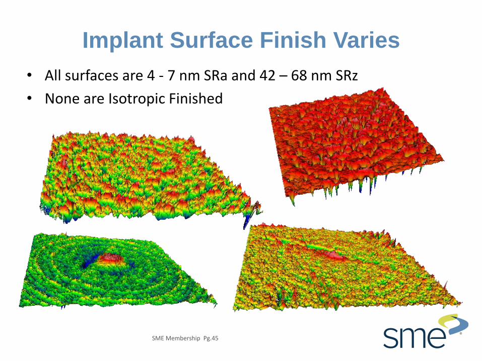
Implant Surface Finish Varies
• All surfaces are 4 - 7 nm SRa and 42 – 68 nm SRz
• None are Isotropic Finished

SME Membership Pg.46
Isotropic Finishing Summary
• Deburring and surface conditioning of complex machined parts is one of the most troublesome problems faced by the metalworking industry.
• High-energy surface finishing can drastically reduce finishing and deburring costs.
• Isotropic Finishing: – Extends tooling and part life.
– Improves wear resistance.
– Reduces fatigue failure.
– Ensures part-to-part uniformity.

Questions?
Dave Davidson
Presenter
Thank you!
Jack R. Clark
Presenter
SME Membership Pg.48
Thank You for Attending
Dave Davidson
Jack R. Clark
SME Membership | http://i.sme.org/home One SME Drive | Dearborn, MI 48121 USA | www.sme.org
Next SME Membership Webinar
3D Printed Carbon Fiber
9/15/15 3:00pm - 4:00 pm (EST)
Register at SME Member X-Press
https://www.xpressreg.net/register/sme/start.asp

SME Membership Pg.49
References
• "The Effect of Surface Finish on Functional Surface Performance". Dr. M.B. Grant, Director of Corporate Metrology, Cummins Engine Company. (SME Paper, presented at the International Grinding Conference, 1990)
• Metal Finishing Magazine, 3 May 2006. Co-authored with Michael Massarsky, PhD, and David A. Davidson, “It's the Finish that Counts”.
• “Expanding the Limits of Interferometric Measurement for Automotive Applications”. Jack R. Clark author ( XI. International Colloquium on Surfaces, Chemnitx, Germany, 2004).
• SME Medical Manufacturing 2008 Annual, pp. 91-93, “Metrology Keeps Hip”.
• Products Finishing Magazine, posted 1 January 2015. Co-authored with David A. Davidson, “Isotropic Mass Finishing for Surface Integrity and Part Performance”.
• "It's the Finish that Counts"
• http://www.slideshare.net/dryfinish/its-the-finish-that-counts
• "The Role of Surface Finish In Improving Part Performance":
• http://www.slideshare.net/dryfinish/november-2012-f4-deburring-1-final?related=1
• "Free Abrasives Flow for Automated Finishing":
• http://www.slideshare.net/dryfinish/october-2013-f2-deburring-1?related=2