Embed Size (px)
Citation preview

Scientific Journal Impact Factor (SJIF): 1.711
International Journal of Modern Trends in Engineering and
Research www.ijmter.com
@IJMTER-2014, All rights Reserved 71
e-ISSN: 2349-9745
p-ISSN: 2393-8161
Single Phase Thirteen Level Inverter using BI Directional Switches and
reduced Switch Count for PV Systems
Kavin.K.S1, Sivasamuthira Pandian.S2, Shasikala.G3 1,2,3Department of Electrical and Electronics Engineering, Er.Perumal Manimekalai College of Engineering,
Hosur, India
Abstract— Renewable energies have advantages of zero fuel cost and reduced environmental
impacts. This paper proposes an Asymmetrical Thirteen level H-Bridge inverter circuit. Two inputs
from solar PV panels are given to the converter and maximum power is extracted by using maximum
power point tracking method. Integrated converter is DC to DC Boost converter. The output is given
to H- inverter which converts dc to ac and the thirteen level output voltage is applied to the load.
Operational analysis and simulation results are given for the proposed circuit.
Keywords-Dc-Dc Boost converter, FPGA controller, H-Bridge inverter with bi-directional switch circuit, Total harmonic distortion (THD).
I. INTRODUCTION
With increasing concern in renewable energy systems with various sources becomes greater
than before. Renewable energy sources such as photovoltaic (PV) and wind energy can be used to
enhance the safety, Reliability and sustainability of a power system. Renewable energy resources
will increasingly an important part of power generation in the new millennium. There is an enormous
need for integrated power converters that are capable of interfacing and controlling several power
terminals with low cost and compact structure. The utilization of natural energy is recognized as a new energy source which will eventually replace conventional energy sources. Renewable energy
sources do not have the high external cost and social issues. Renewable energy sources such as wind, solar, fuel cell holds more potential to meet our energy demands. This proposal focuses on control of
one major renewable-energy source PV and the output of the PV panel is converted to AC by using the thirteen level asymmetrical H-bridge Inverter configurations.
II. MULTILEVEL INVERTER Multilevel inverter is the generation of high voltage using lower voltage rating devices
connected in series. Also it has the potential to get a high quality output voltage by producing multi
output voltage levels. However it increases the number of switching devices and other components,
which result in an increase of complexity problems and systems cost. Many multilevel inverter
configurations have been researched to get sinusoidal like output voltage wave with minimum circuit
components. A Multilevel inverter has several advantages over a conventional two level converter
that uses high switching frequency pulse width modulation (PWM). The attractive features of a multi
level inverter can be briefly summarized as follows. Staircase waveform quality: Multilevel inverters
not only can generate the output voltages with low distortion, but also can reduce the dv/dt stresses;
therefore electromagnetic compatibility (EMC) problems can be reduced. Common mode voltage:
Multilevel inverters produce small CM voltage, therefore the stress in the bearings of a motor
connected to a multilevel motor drive can be reduced. Furthermore CM voltages can be eliminated
by using advanced modulation technique. Input current: Multilevel inverters can draw input current
with low distortion. Switching frequency: Multilevel inverters can operate at both fundamental frequency and high switching frequency PWM. It should be noted that lower switching frequency
means lower switching loss and higher efficiency. There are several multilevel converters are commercialized for high power applications such as Flexible AC transmission systems (FACTS)

International Journal of Modern Trends in Engineering and Research (IJMTER)
Volume 01, Issue 05, [November - 2014] e-ISSN: 2349-9745, p-ISSN: 2393-8161
@IJMTER-2014, All rights Reserved 72
Controllers, Train Traction, Automotive applications, renewable energy power conversion and
transmission etc.
III. PROPOSED MULTILEVEL INVERTER
The proposed single-phase Thirteen - level inverter was developed from the seven - level
inverter. It comprises two single-phase conventional H-bridge inverter, two bidirectional switches,
and two capacitor voltage divider formed by C1, C2, C3 and C4 as shown in Fig. The modified H-
bridge topology is significantly advantageous over other topologies, i.e., less power switch, power
diodes, and less capacitor for inverters of the same number of levels. Photovoltaic (PV) arrays were
connected to the inverter via a dc–dc boost converter. The power generated by the inverter is to
delivered was required because the PV to the load. The dc–dc boost converter arrays had a voltage
that was lower than the load voltage. High dc bus voltages are necessary to ensure that power flows
from the PV arrays to the load. Proper switching of the inverter can produce thirteen output-voltage
levels of (Vdc, 5/6Vdc, 4/6Vdc, 3/6Vdc, 2/6Vdc, 1/6Vdc, 0, -5/6Vdc, -4/6Vdc, -3/6Vdc, -2/6Vdc, -
1/6Vdc,-Vdc) from the dc supply voltage. The switching states are easily understood from the mat
lab programs for both the H- bridge inverters.
Fig 1. Thirteen level Inverter Circuit diagram
IV. PWM GENERATION
The PWM Signal was generated in this thirteen level inverter is a single reference sine wave
frequency of 50 Hz is compared with a triangular carrier wave frequency of 10 KHz. The amplitude
of the sine wave is taken in different offset values. There are three offset sine wave is compared with
a triangular wave and the PWM.
Fig 2. PWM generation technique

International Journal of Modern Trends in Engineering and Research (IJMTER)
Volume 01, Issue 05, [November - 2014] e-ISSN: 2349-9745, p-ISSN: 2393-8161
@IJMTER-2014, All rights Reserved 73
V. SIMULATION AND EXPERIMENTAL RESULTS
MATLAB SIMULINK simulated the proposed configuration before it was physically implemented in a prototype. The different amplitude of reference sine wave is compared with a
triangular wave and the PWM signal is generated. Here the switching device is MOSFET and the
two bi directional devices are IGBT. The processor used here is FPGA (Field Programmable Gate
Array). It’s under the category of Very large scale integration system. In FPFA many of the pins are
multiplexed pins. So we can use it as either input or output pins. The operating speed of the Spartan
3E controller operating speed is much greater than Digital signal processors. These controllers are
used to generate the PWM pulses to the thirteen level inverter.
Fig 3. PWM pulses to the Inverter switch S1, S2, S3, S4
Fig 4. PWM pulses to the Inverter switch S5
Fig 5. PWM pulses to the Inverter switches S6, S7, S8,S9
International Journal of Modern Trends in Engineering and Research (IJMTER)
Volume 01, Issue 05, [November - 2014] e-ISSN: 2349-9745, p-ISSN: 2393-8161
@IJMTER-2014, All rights Reserved 74
Fig 6. PWM pulses to the Inverter switch S10
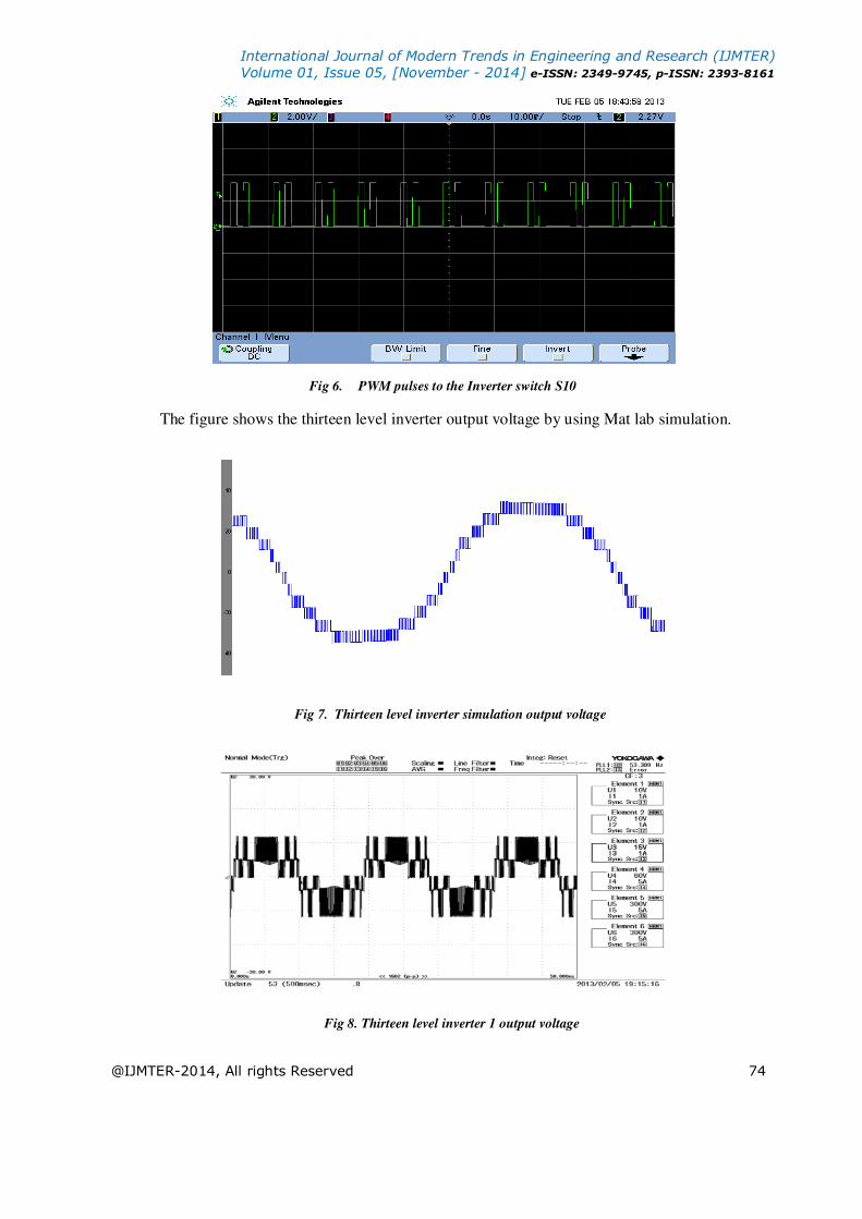
The figure shows the thirteen level inverter output voltage by using Mat lab simulation.
Fig 7. Thirteen level inverter simulation output voltage
Fig 8. Thirteen level inverter 1 output voltage

International Journal of Modern Trends in Engineering and Research (IJMTER)
Volume 01, Issue 05, [November - 2014] e-ISSN: 2349-9745, p-ISSN: 2393-8161
@IJMTER-2014, All rights Reserved 75
Fig 9. Thirteen level Inverter 2 output voltage
Fig 10. Thirteen level inverter hardware output voltage
Fig 11. Experimental setup for the single phase thirteen levels PWM inverter.

International Journal of Modern Trends in Engineering and Research (IJMTER)
Volume 01, Issue 05, [November - 2014] e-ISSN: 2349-9745, p-ISSN: 2393-8161
@IJMTER-2014, All rights Reserved 76
VI. THD RESULT
By using YOKOGAWA the harmonics result is analysed.
Fig 12. THD Result.
Fig 13. THD bar chart.
VII. CONCLUSIONS
Multilevel inverters offer improved output waveforms and lower THD. This paper has presented a novel PWM switching scheme for the proposed multilevel inverter. In this paper three
reference signals and is compared with a triangular wave signal to generate the PWM signals. Here
there are two different DC voltage levels are used for the two H-Bridge inverters. So this method of configuration is known as asymmetrical cascaded inverter. By controlling the modulation index and
different levels of Dc voltages the thirteen levels of the output voltage’s achieved. A FPGA XILINS SPARTAN 3E is optimized the performance of the inverter. The THD level of this thirteen level
inverter is 3.530 %.
REFERENCES [1]. L G. Franquelo,J. Rodríguez, J. I. Leon,S. Kouro, R. ortillo,and M. A.M. Prats, “ The age of multilevel converters
arrives,” IEEE Ind.Elelctron. Magazine, June 2008.

International Journal of Modern Trends in Engineering and Research (IJMTER)
Volume 01, Issue 05, [November - 2014] e-ISSN: 2349-9745, p-ISSN: 2393-8161
@IJMTER-2014, All rights Reserved 77
[2] E.Najafi and A.H.M.Yatim, “Design and Implementation of a new multilevel inverter topology,” IEEE Ind.Elelctron.,
vol.59, no.11, Nov 2012.
[3]L.M Tolbert, F.Z.Peng and T.G Habelter, “Multilevel Converter for large electric drives,” IEEE trans.Ind.Appl. Vol
35, no.1, pp. 36-44, Jan/Feb.1999.
[4].K.Nakata, K.Nakamura, S.Ito and K.Jinbo, “A three level traction inverter with IGBTs for EMU”, in Conf.Rec.IEEE
IAS Annu.meeting, 1994, vol.1, pp.667-672.
[5].A.Jidin,N.R, N.R, N.R. N.Idris, A.H.M.Yatim, t.Sutikno and E.Elbuluk,”An optimized switching strategy for quick
dynamic torque control in DTC-hysteresis-based induction machines,” IEEE trans.Ind.Electron. vol.58, no.8,pp
33913400,Aug.2011.
[6]. K.Y.Lau, M.F.M.Yousof, S.N.M Arshad, M.Anwari and A.H.M. Yatim, “Performance analysis of hybrid
photovoltaic/diesel energy under Malaysian condition,” J.Energy, Vol.35, no.8, pp. 3245-3255, Aug. 2010.
[7]. M. F.Kangarlu, E.Babaei, “A generalized cascaded multilevel inverter using series connection of sub multilevel
inverters,” IEEE Trans.Power Electron, vol.28, no.2, pp.625-636, Feb 2013.
[8] E.Babaei, “A new cascaded multilevel inverter topology with minimum switches,” IEEE Trans.Power Electron. Vol
23, no.6, pp. 2657- 2664, Nov.2008.
[9] M. Calais and V. G. Agelidis, “Multilevel converters for single-phase grid connected photovoltaic systems—An
overview,” in Proc. IEEE Int. Symp Ind. Electron., 1998, vol. 1, pp. 224–229.
[10] S. B. Kjaer, J. K. Pedersen, and F. Blaabjerg, “A review of single-phase grid connected inverters for photovoltaic
modules,” IEEE Trans. Ind Appl., vol. 41, no. 5, pp. 1292–1306, Sep./Oct. 2005.
[11] P. K. Hinga, T. Ohnishi, and T. Suzuki, “A new PWM inverter for photovoltaic power generation system,” in Conf.
Rec. IEEE Power Electron. Spec. Conf., 1994, pp. 391–395.
[12] Y. Cheng, C. Qian, M. L. Crow, S. Pekarek, and S. Atcitty, “A comparison of diode-clamped and cascaded multilevel converters for a STATCOM with energy storage,” IEEE Trans. Ind. Electron., vol. 53, no. 5, pp. 1512– 1521,
Oct. 2006.