Embed Size (px)
DESCRIPTION
Citation preview

Assertion Based Verification and Interfaces
Session delivered by:
Padmanaban K .
Session-08

312
Immediate Assertions
• Immediate assertions, as the name implies, executeimmediately, in zero simulation time.
• Immediate assertions can be placed anywhere proceduralstatements can be placed; within always blocks, initialblocks, tasks, and functions.
• Any procedural statement can be used in the pass or failstatement part of an immediate assertion.
• Care must be taken to ensure that no design functionality ismodeled in the pass/fail parts of an assertion, because it willbe ignored by synthesis, thus causing a modeling differencebetween simulation and synthesis.
313
Immediate Assertions
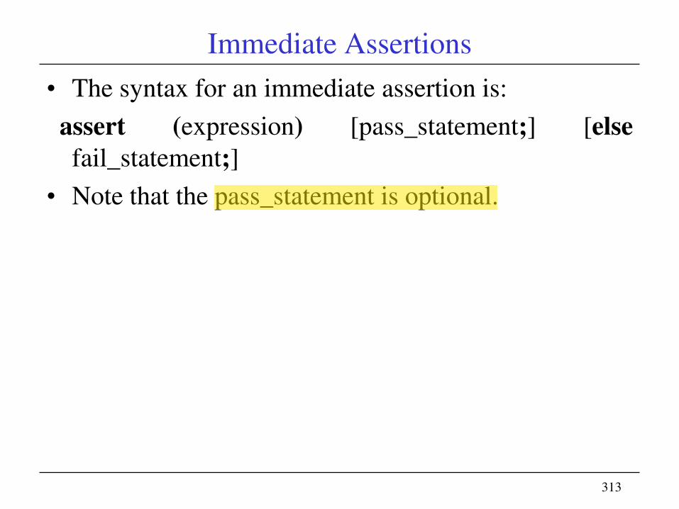
• The syntax for an immediate assertion is:
assert (expression) [pass_statement;] [else
fail_statement;]
• Note that the pass_statement is optional.

314
Immediate Assertion Example 1
module example_1 (
input ifcond, a, b,
output logic if_out
);
always_comb begin
assert (^ifcond !== 1‘bx)else $error("ifcond = X");
if (ifcond)
if_out = a;
else
if_out = b;
end
endmodule

315
Immediate Assertion example 2module example_2 (
input a, b, c, d,
input [1:0] sel,
output logic out);
always_comb begin
assert (^sel !== 1‘bx)else $error("case_Sel = X");
case (sel)
2'b00 : out = a;
2'b01 : out = b;
2'b10 : out = c;
2'b11 : out = d;
endcase
end
endmodule

316
Immediate Assertion example 3
module and_or (in1, in2, and_out, or_out);
input in1, in2;
output and_out, or_out;
assign or_out = in1 | in2;
assign and_out = in1 & in2;
always_comb begin
assert (^{in1, in2} !== 1‘bx)else $error (―logic inputs = X‖);endmodule

317
Immediate Assertion
• An immediate assertion may include a pass statement and/or a fail statement. In our example the pass statement is omitted, so no action is taken when the assert expression is true.
• If the pass statement exists: assert (A == B) $display ("OK. A equals B");
• It is executed immediately after the evaluation of the assert expression. The statement associated with an else is called a fail statement and is executed if the assertion fails:
• assert (A == B) $display ("OK. A equals B"); else $error ("It's gone wrong");
• Note that you can omit the pass statement and still have a fail statement:
318
Concurrent Assertions
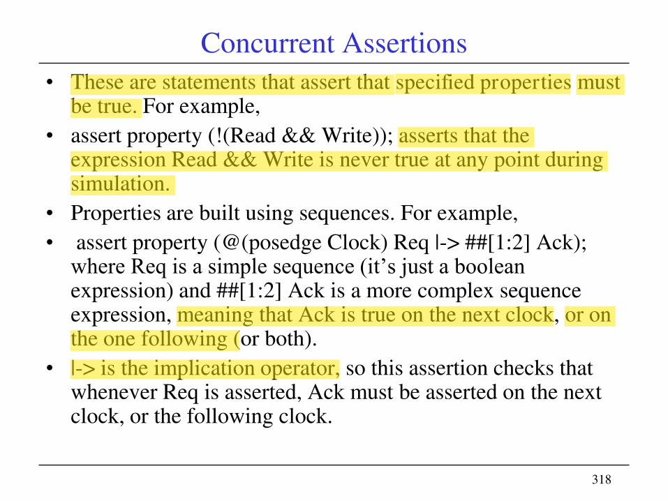
• These are statements that assert that specified properties must be true. For example,
• assert property (!(Read && Write)); asserts that the expression Read && Write is never true at any point during simulation.
• Properties are built using sequences. For example,
• assert property (@(posedge Clock) Req |-> ##[1:2] Ack); where Req is a simple sequence (it‘s just a boolean expression) and ##[1:2] Ack is a more complex sequence expression, meaning that Ack is true on the next clock, or on the one following (or both).
• |-> is the implication operator, so this assertion checks that whenever Req is asserted, Ack must be asserted on the next clock, or the following clock.

319
Concurrent Assertions
• Concurrent Assertions – Concurrent assertions describe
behavior that spans over time.
• Unlike immediate assertions, the evaluation model is based
on a clock such that a concurrent assertion is evaluated only
at the occurrence of a clock tick.
• The values of variables used in the evaluation are the
sampled values.
• Concurrent assertions like these are checked throughout
simulation. They usually appear outside any initial or always
blocks in modules, interfaces and programs.
• Concurrent assertions (assert property and cover property
statements) use a generalized model of a clock and are only
evaluated when a clock tick occurs.

320
Concurrent assertions
• Based on clock cycles.
• Test expression is evaluated at clock edges based on the
sampled values of the variables involved.
• Sampling of variables is done in the "preponed" region and
the evaluation of the expression is done in the "observed"
region of the scheduler.
• Can be placed in a procedural block, a module, an interface
or a program definition.
• Can be used with both static (formal) and dynamic
verification (simulation) tools.
A sample concurrent assertion is shown below.
a_cc: assert property(®(posedge elk)
not (a && b));

Two requests before grant


Assertions in Verilog and SV


Checks for a shift register

Simple RAM with assertions

Sequence with edge definitions
328
Introduction to Interface in SystemVerilog
• The increasing features of electronic gadgets in the markettoday have increased the number of blocks in the system.
• The complexity involved in handling the communicationbetween the multiple blocks of a digital system affect everyaspect of design from RTL coding to hardware-softwarepartitioning to performance analysis to bus implementationchoices and protocol checking
• To enhance the handling capability for block levelconnections, ―interface‖ construct was introduced inSystemVerilog .
• In its simplest form, an interface can be considered a bundleof wires. This is defined independent from the modules,separately.

329
Introduction to Interface in SystemVerilog
• In Verilog, one module is connected to another through
module ports.
• In order to define the specific ports of each module that
makes up the design, a detailed knowledge of the intended
hardware design is required.
• Generally, many ports repeat in several modules and thus
require redundant port definitions for each module which is
also prone to errors
330
Interface Principle
• Modules can use an interface the same as if it were a single
port. If all the modules using the interface share a common
functionality, the can be included in the interface itself. In
addition, an interface can include built-in protocol checking

331
Module Port Declaration in Verilog
• In the complex designs, the top module is connected to
multiple child modules.
• The connection between the top and child modules may be
composed of many ports.
• Both the modules must separately declare each port and when
the modules are instantiated each signal needs to be defined
separately to map each port to connect to the design block.

332
Example
module top;
logic req, gnt, start, rdy;
logic clk = 0;
logic [7:0] addr;
wire [7:0] data;
mem m1 (clk, req, start,
addr, data, gnt, rdy);
cpu c1 (clk, gnt, rdy, data,
req, start, addr);
... // further code for functionality

333
Example
module mem (input logic clk, req, start,
logic [7:0] addr,
output logic [7:0] data,
logic gnt, rdy);
... // further code for functionality
module cpu (input logic clk, gnt, rdy,
logic [7:0] data,
output logic req, start,
logic [7:0] addr);
... // further code for functionality

334
Interface Necessity
– The connection between the modules mem and cpu is
composed of the various signals viz reg, gnt, start, rdy,
mode, addr and data.
– These connections are to be repeatedly defined in the
declarations of each of mem, cpu and top modules Also,
the repetition of the ports is also required at each
instantiation. As each port must be declared in several
places, the construction of such hierarch consumes time.
– In case, any of the communication signal between the two
modules changes, either by addition or deletion of a
signal, or by change in the behavior of a signal,
simultaneous changes are required at all the places to
reflect that for correctness of the design

335
Interfaces : Edge over Module Port

336
Interface Block

337
Interface concept
• To reduce the burden of repetitive definition of the ports and
the headache involved when there is any change in the ports
the interface construct of SystemVerilog comes to the rescue
of the design engineer.
• SystemVerilog allows the bus to be declared once as an
interface.
• An interface is a design unit like a module, i.e. it is declared
in a separate file and compiled separately. To get the clarity
of the edge interface provides over simple port declarations,
the same example discussed above is modified with usage of
interface

338
Interface Declaration
// interface declaration
interface bus_if;
logic req, start, gnt, rdy;
logic [7:0] addr, data;
endinterface : bus_if
module mem (input logic clk,
bus_if bus);
... // further code for functionality
module cpu (input logic clk,
bus_if bus);
... // further code for functionality
339
Interface Instantiation
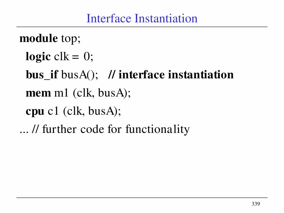
module top;
logic clk = 0;
bus_if busA(); // interface instantiation
mem m1 (clk, busA);
cpu c1 (clk, busA);
... // further code for functionality

340
Simple Example Without Interfaces
module memMod(input logic req,
bit clk,
logic start,
logic[1:0] mode,
logic[7:0] addr,
inout logic[7:0] data,
output logic gnt,
logic rdy);
always @(posedge clk)
gnt <= req & avail;
endmodule
module cpuMod(input bit clk,
logic gnt,
logic rdy,
inout logic [7:0] data,
output logic req,
logic start,
logic[7:0] addr,
logic[1:0] mode);
endmodule
module top;logic req,gnt,start,rdy;bit clk = 0;logic [1:0] mode;logic [7:0] addr,data;
memMod mem(req,clk,start,mode,addr,data,gnt,rdy);
cpuMod cpu(clk,gnt,rdy,data,req,start,addr,mode);
endmodule
Top clk
CPU Mem
req
startgntrdymode[1:0]
addr[7:0]
data[7:0]

341
Simple Example Using Interfaces
interface simple_bus;
logic req,gnt;
logic [7:0] addr,data;
logic [1:0] mode;
logic start,rdy;
endinterface: simple_bus
module memMod(simple_bus a,
input bit clk);
logic avail;
always @(posedge clk)
a.gnt <= a.req & avail;
endmodule
module cpuMod(simple_bus b,
input bit clk);
endmodule
module top;
bit clk = 0;
simple_bus sb_intf;
memMod mem(sb_intf, clk);
cpuMod cpu(sb_intf, clk);
endmodule
Top
CPU Memsb_intf
clk
Bundle
signals in
interfacesim
ple
_buss
imp
le_
bus
342
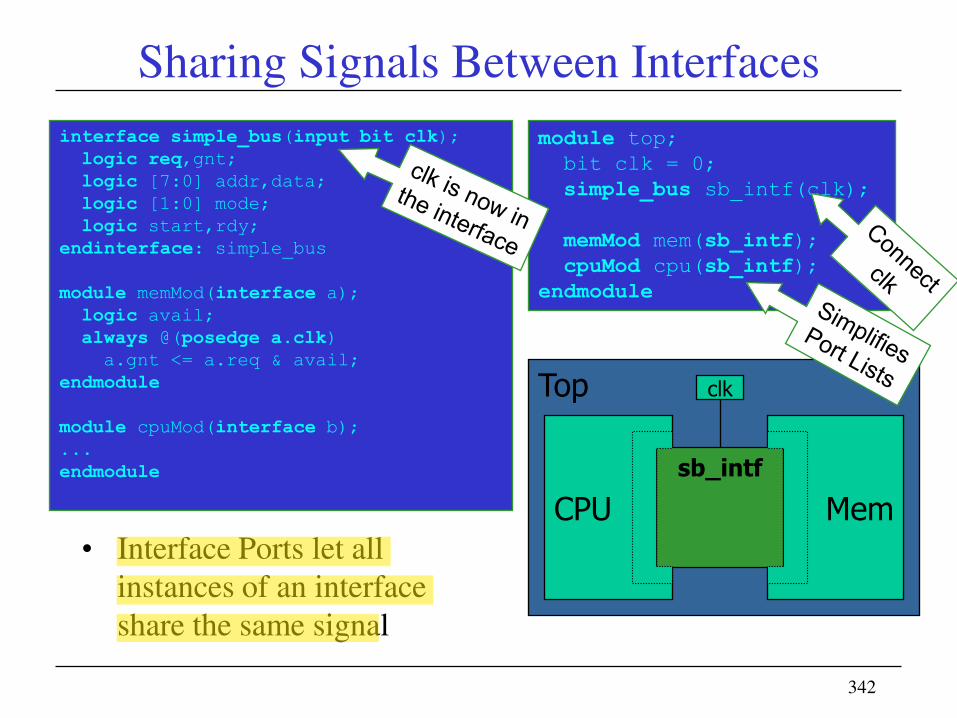
Sharing Signals Between Interfaces
interface simple_bus(input bit clk);
logic req,gnt;
logic [7:0] addr,data;
logic [1:0] mode;
logic start,rdy;
endinterface: simple_bus
module memMod(interface a);
logic avail;
always @(posedge a.clk)
a.gnt <= a.req & avail;
endmodule
module cpuMod(interface b);
...
endmodule
module top;
bit clk = 0;
simple_bus sb_intf(clk);
memMod mem(sb_intf);
cpuMod cpu(sb_intf);
endmodule
Top
CPU Mem
clk
sb_intf
• Interface Ports let all
instances of an interface
share the same signal

343
Summary• An assertion is a description of an intended design
property. The assertion observes the design and evaluates to true or false based on design behaviors.
• Immediate assertions can be placed anywhere proceduralstatements can be placed; within always blocks, initialblocks, tasks, and functions.
• Add assertions to each internal interface of a block. Theseassertions help to define the interface protocol, legal valuesrequired sequencing, and so forth.
• An interface may be parameterized in the same way as amodule. Also, a module header can be created with anunspecified interface instantiation, called a GenericInterface.


![Manoj.ghadge_OTPR.course [Session 8]](https://img.pdfslide.us/doc/110x75/563dbb54550346aa9aac3bb0/manojghadgeotprcourse-session-8.jpg)