Embed Size (px)
DESCRIPTION
Synchronous Digital Hierarchy and Time Division Multiplexing
Citation preview
TDM and SDH Basics
TDM Time Division Multiplexing
SDH Synchronous Digital Hierarchy
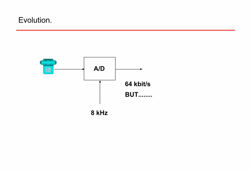
Evolution.
A/D
8 kHz
64 kbit/s
BUT........
T1 T2 T3
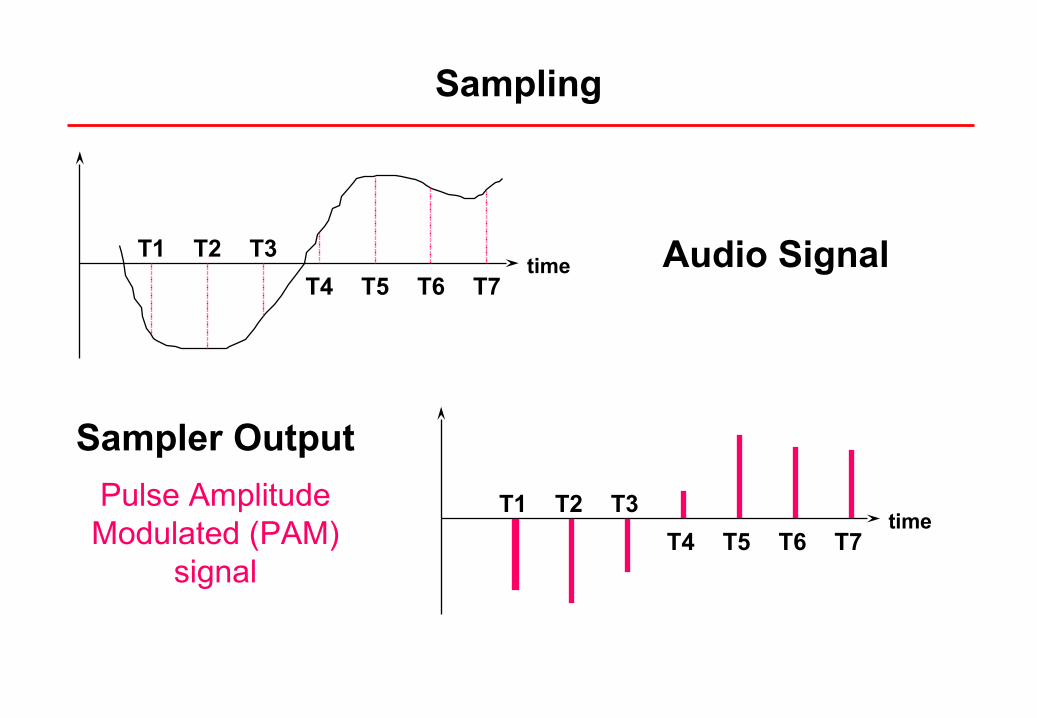
T4 T5 T6 T7time Audio Signal
Sampler Output
timeT1 T2 T3
T4 T5 T6 T7
Pulse Amplitude Modulated (PAM)
signal
Sampling
+V0 0 0 0 X XXX0 0 0 1 X XXX0 0 1 0 X XXX
1 0 0 0 X XXX1 0 0 1 X XXX
1 0 1 0 X XXX1 0 1 1 X XXX1 1 0 0 X XXX1 1 0 1 X XXX1 1 1 0 X XXX1 1 1 1 X XXX
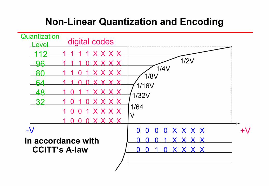
digital codes
-VIn accordance with
CCITT’s A-law
1/2V1/4V
1/8V1/16V
1/32V
1/64V
Quantization Level
3248648096112
Non-Linear Quantization and Encoding
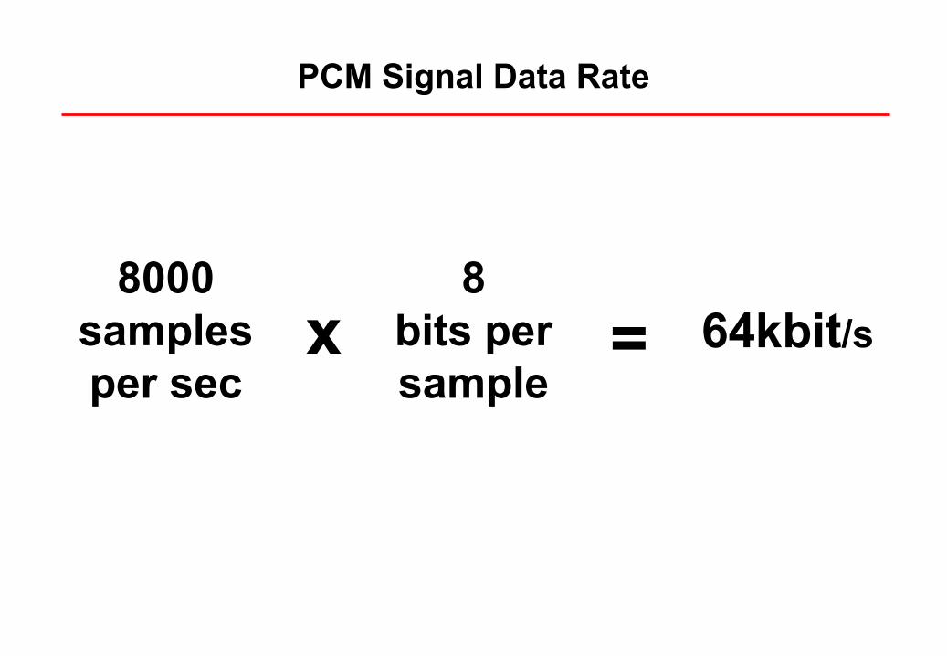
8bits per sample
x = 64kbit/s8000
samples per sec
PCM Signal Data Rate
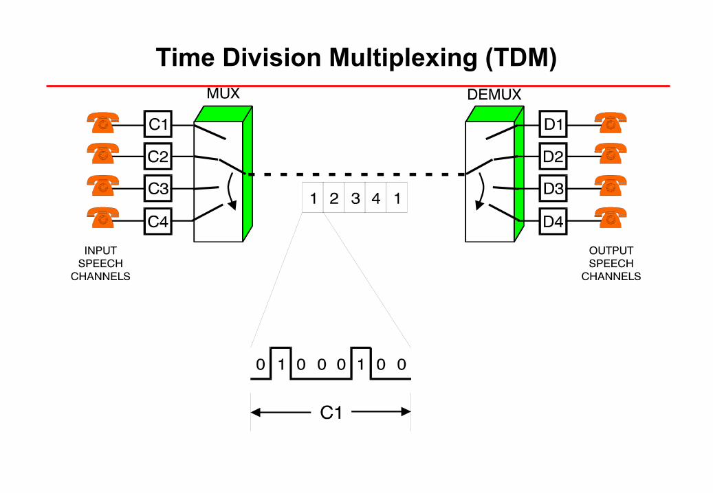
Time Division Multiplexing (TDM)
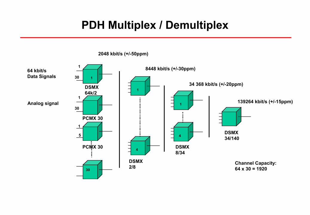
64 kbit/s Data Signals
139264 kbit/s (+/-15ppm)
1
2048 kbit/s (+/-50ppm)
8448 kbit/s (+/-30ppm)
34 368 kbit/s (+/-20ppm)
64 Channel Capacity:64 x 30 = 1920
DSMX34/140
DSMX8/34
DSMX2/8
1
30
DSMX64k/2
1
30
PCMX 30
1
PCMX 30
5
1
30
4
1
4
PDH Multiplex / Demultiplex
Analog signal
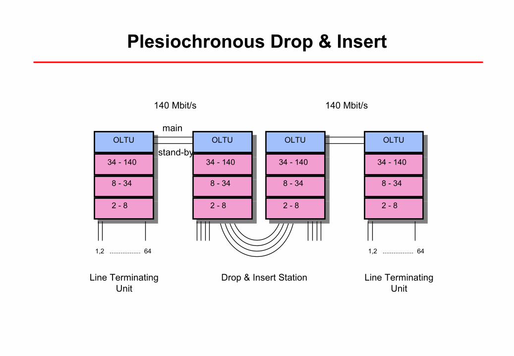
OLTU
34 - 140
8 - 34
2 - 8
OLTU
34 - 140
8 - 34
2 - 8
OLTU
34 - 140
8 - 34
2 - 8
OLTU
34 - 140
8 - 34
2 - 8
main
stand-by
140 Mbit/s 140 Mbit/s
Line Terminating Unit
Line Terminating Unit
Drop & Insert Station
1,2 ................. 64 1,2 ................. 64
Plesiochronous Drop & Insert
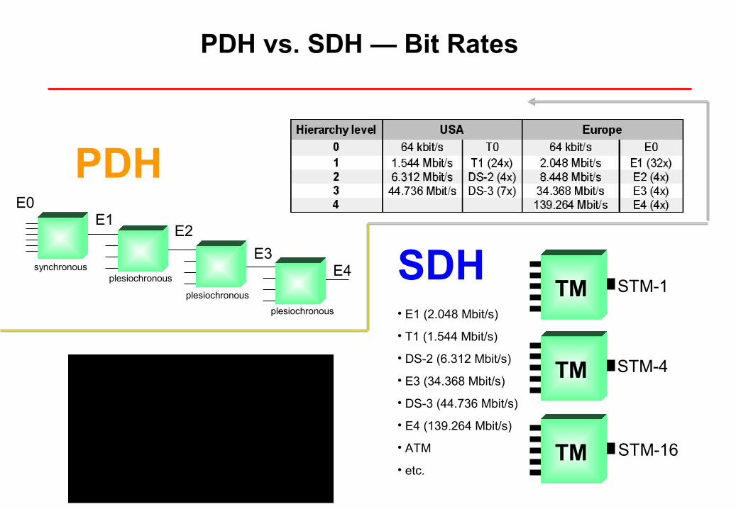
PDH vs. SDH — Bit Rates
E1E0
E2
E3E4
plesiochronous
plesiochronous
plesiochronous
synchronous
TM STM-1
TM STM-4
TM STM-16
• E1 (2.048 Mbit/s)
• T1 (1.544 Mbit/s)
• DS-2 (6.312 Mbit/s)
• E3 (34.368 Mbit/s)
• DS-3 (44.736 Mbit/s)
• E4 (139.264 Mbit/s)
• ATM
• etc.
PDH
SDH
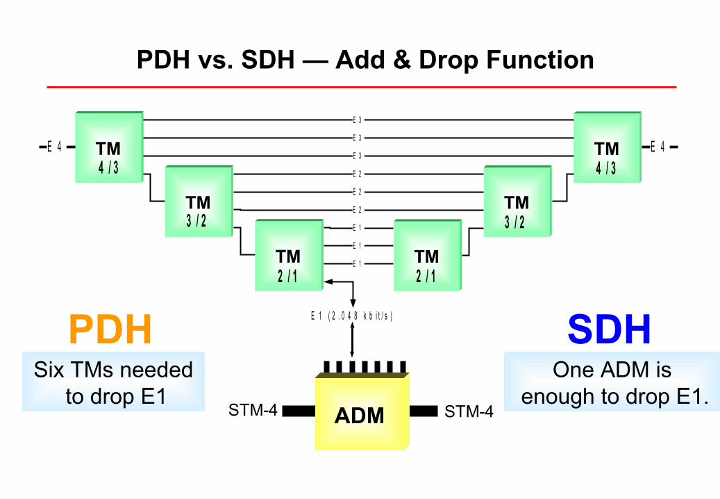
PDH vs. SDH — Add & Drop Function
ADM STM-4STM-4
Six TMs needed to drop E1
One ADM is enough to drop E1.
TM TM
TMTM
TMTM
E 3
E 3
E 3
E 2
E 2
E 1
E 1
E 1
E 4 E 4
E 1 ( 2 . 0 4 8 k b i t / s )
E 2
2 / 1 2 / 1
3 / 23 / 2
4 / 3 4 / 3
PDH SDH
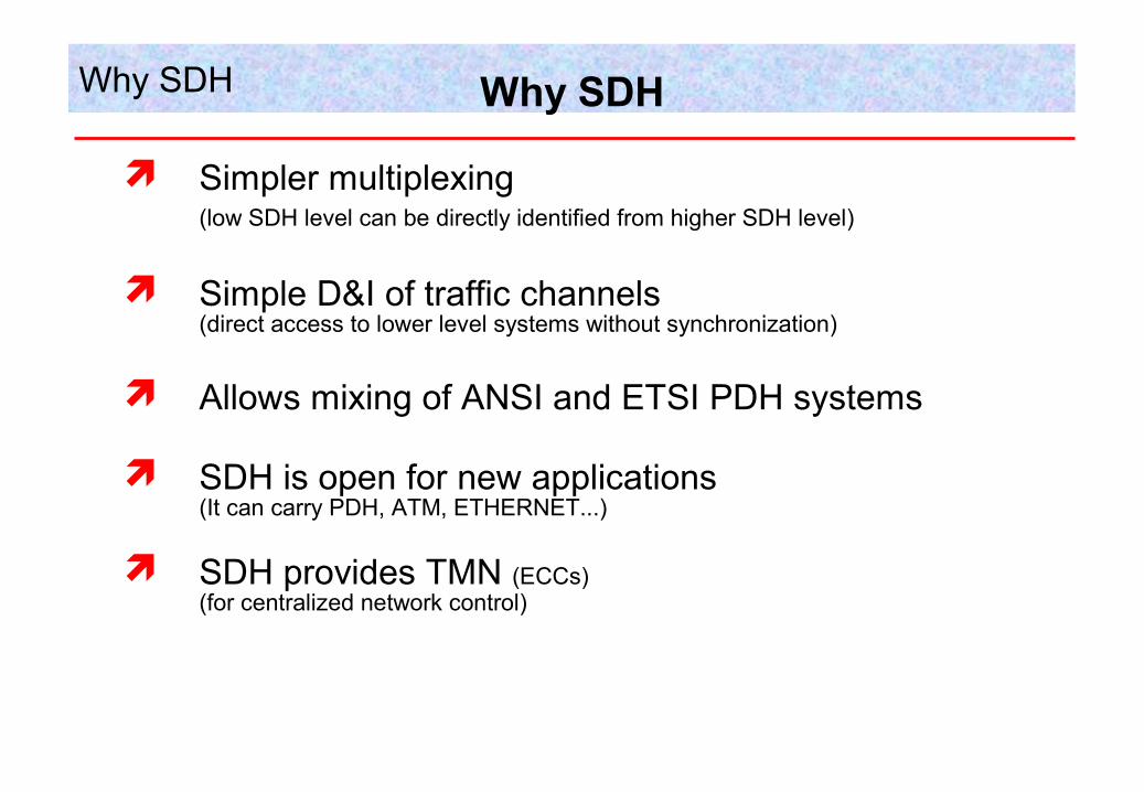
Simpler multiplexing(low SDH level can be directly identified from higher SDH level)
Simple D&I of traffic channels(direct access to lower level systems without synchronization)
Allows mixing of ANSI and ETSI PDH systems
SDH is open for new applications (It can carry PDH, ATM, ETHERNET...)
SDH provides TMN (ECCs)(for centralized network control)
Why SDH Why SDH
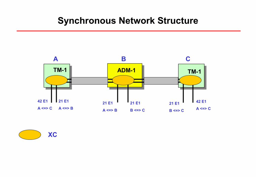
Synchronous Network Structure
TM-1 ADM-1 TM-1
A CB
42 E1
A <=> C
21 E1
A <=> B21 E1
A <=> B
21 E1
B <=> C
42 E1
A <=> C21 E1
B <=> C
XC
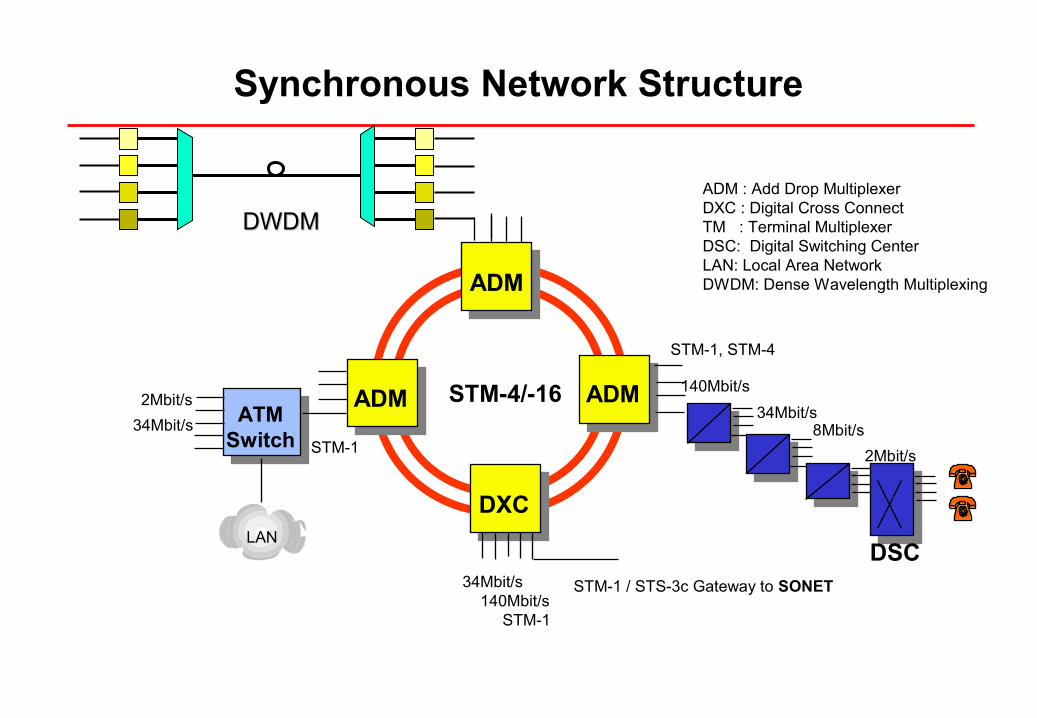
34Mbit/s 140Mbit/s STM-1
STM-1 / STS-3c Gateway to SONET
DXC
ADMADM ATMSwitch
STM-4/-162Mbit/s
34Mbit/sSTM-1
LAN
ADM
STM-1, STM-4
2Mbit/s
8Mbit/s34Mbit/s
140Mbit/s
ADM : Add Drop MultiplexerDXC : Digital Cross ConnectTM : Terminal MultiplexerDSC: Digital Switching CenterLAN: Local Area NetworkDWDM: Dense Wavelength Multiplexing
DSC
Synchronous Network Structure
DWDMDWDM
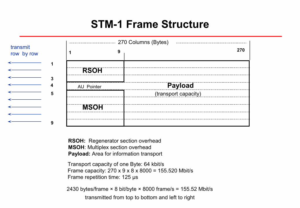
RSOH: Regenerator section overheadMSOH: Multiplex section overheadPayload: Area for information transport
Transport capacity of one Byte: 64 kbit/sFrame capacity: 270 x 9 x 8 x 8000 = 155.520 Mbit/sFrame repetition time: 125 µs
1
3
5
9
4
270
270 Columns (Bytes)
1 9transmitrow by row
RSOH
MSOH
AU Pointer Payload(transport capacity)
STM-1 Frame Structure
2430 bytes/frame × 8 bit/byte × 8000 frame/s = 155.52 Mbit/s
transmitted from top to bottom and left to right
1
3
5
9
4
270
270 Columns (Bytes)
1 9
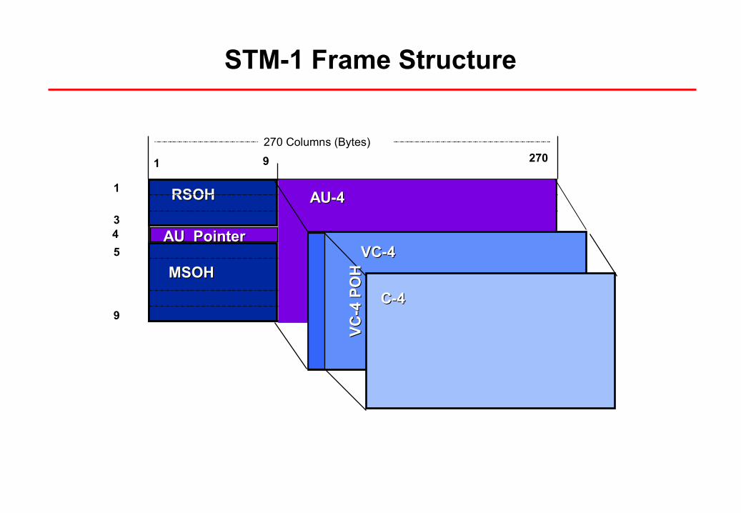
RSOHRSOH
MSOHMSOH
AU-4AU-4
AU PointerAU PointerVC-4VC-4
VC
-4 P
OH
VC
-4 P
OH
C-4C-4
STM-1 Frame Structure
Basic Elements of STM-1
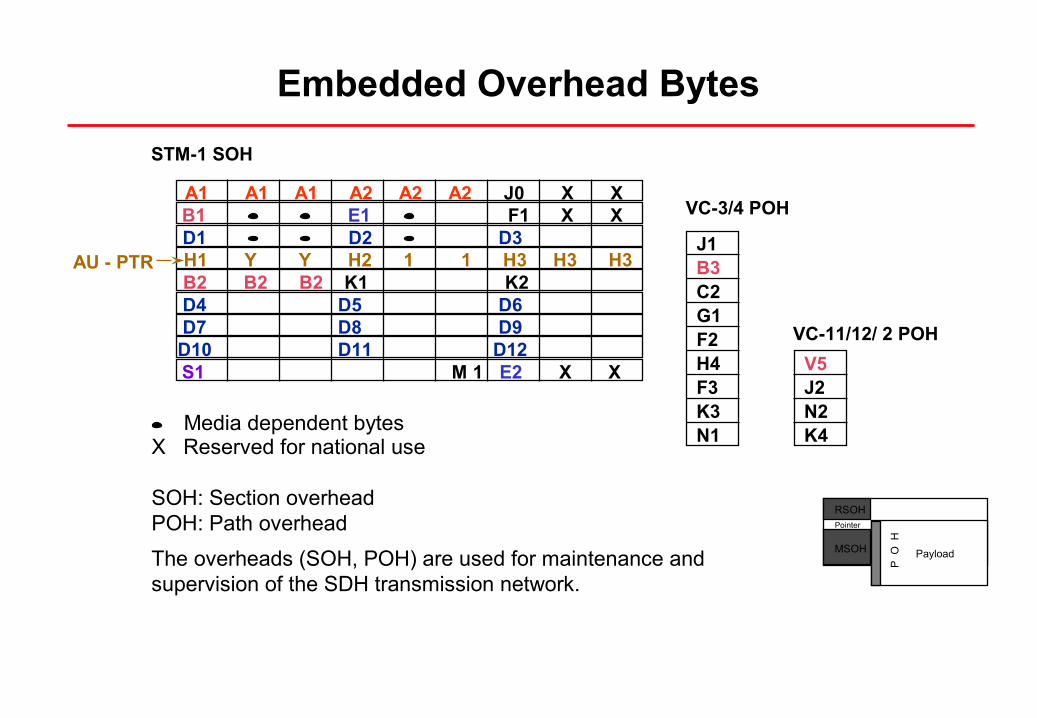
J1B3C2G1F2H4F3K3N1
V5J2N2K4
AU - PTR
VC-3/4 POH
VC-11/12/ 2 POH
STM-1 SOH
Media dependent bytesX Reserved for national use
SOH: Section overheadPOH: Path overhead
The overheads (SOH, POH) are used for maintenance and supervision of the SDH transmission network.
RSOH
MSOH Payload
P
O
H
Pointer
A1 A1 A1 A2 A2 A2 J0 X X
D1 D2 D3
B2 B2 B2 K1 K2D4 D5 D6 D7 D8 D9
D10 D11 D12 S1 M 1 E2 X X
B1 E1 F1 X X
H1 Y Y H2 1 1 H3 H3 H3
Embedded Overhead Bytes
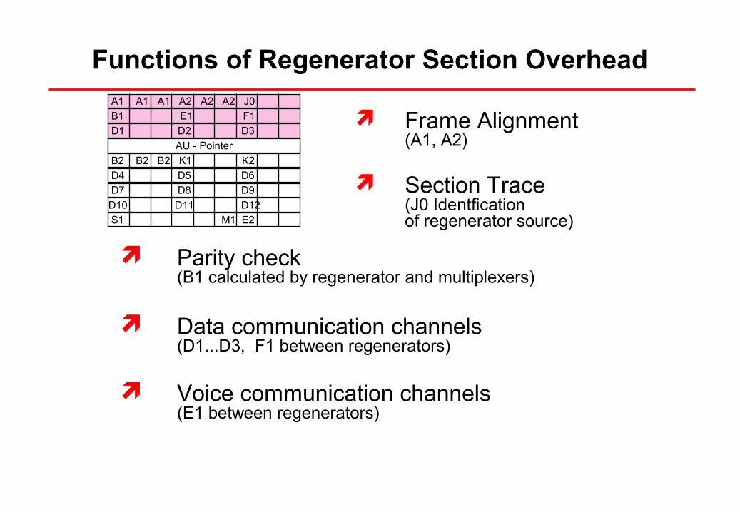
Parity check(B1 calculated by regenerator and multiplexers)
Data communication channels(D1...D3, F1 between regenerators)
Voice communication channels(E1 between regenerators)
Frame Alignment(A1, A2)
Section Trace(J0 Identfication of regenerator source)
A1 A1 A1 A2 A2 A2 J0
B1 E1 F1
D1 D2 D3
B2 B2 B2 K1 K2
D4 D5 D6
D7 D8 D9
D10 D11 D12
S1 M1 E2
AU - Pointer
Functions of Regenerator Section Overhead
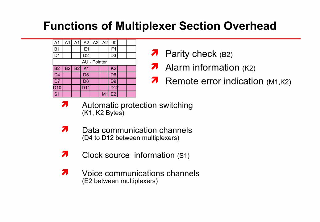
Parity check (B2)
Alarm information (K2)
Remote error indication (M1,K2)
Automatic protection switching(K1, K2 Bytes)
Data communication channels(D4 to D12 between multiplexers)
Clock source information (S1)
Voice communications channels(E2 between multiplexers)
A1 A1 A1 A2 A2 A2 J0
B1 E1 F1
D1 D2 D3
B2 B2 B2 K1 K2
D4 D5 D6
D7 D8 D9
D10 D11 D12
S1 M1 E2
AU - Pointer
Functions of Multiplexer Section Overhead
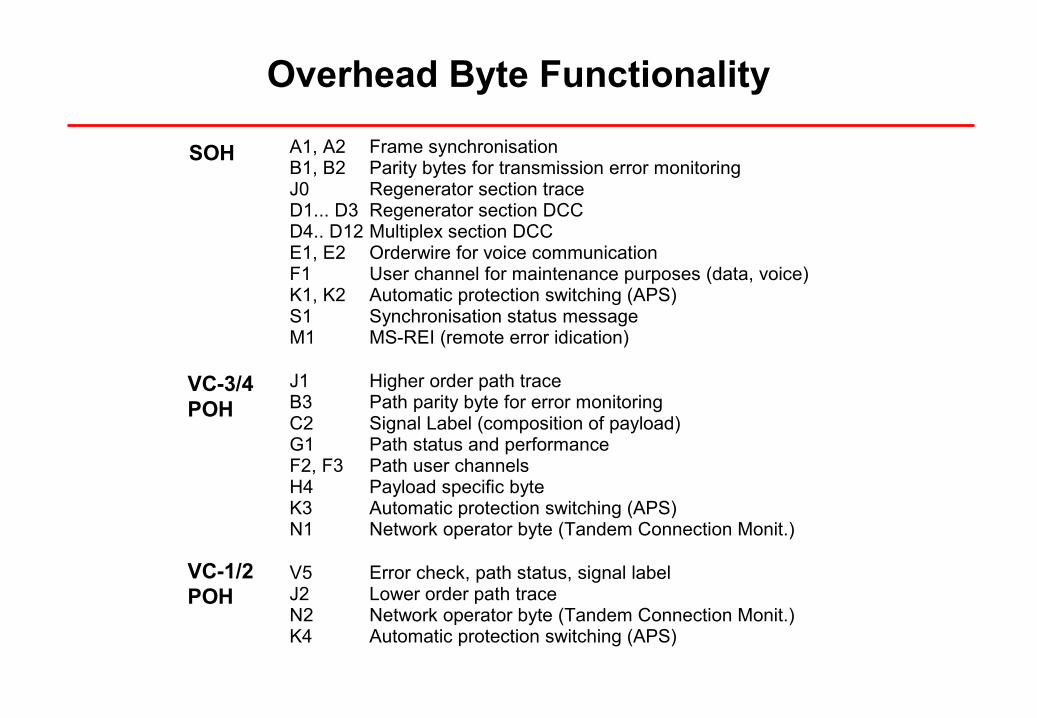
A1, A2 Frame synchronisationB1, B2 Parity bytes for transmission error monitoringJ0 Regenerator section trace D1... D3 Regenerator section DCCD4.. D12 Multiplex section DCCE1, E2 Orderwire for voice communicationF1 User channel for maintenance purposes (data, voice)K1, K2 Automatic protection switching (APS)S1 Synchronisation status messageM1 MS-REI (remote error idication)
J1 Higher order path traceB3 Path parity byte for error monitoringC2 Signal Label (composition of payload)G1 Path status and performanceF2, F3 Path user channelsH4 Payload specific byteK3 Automatic protection switching (APS)N1 Network operator byte (Tandem Connection Monit.)
V5 Error check, path status, signal labelJ2 Lower order path traceN2 Network operator byte (Tandem Connection Monit.)K4 Automatic protection switching (APS)
SOH
VC-3/4POH
VC-1/2POH
Overhead Byte Functionality
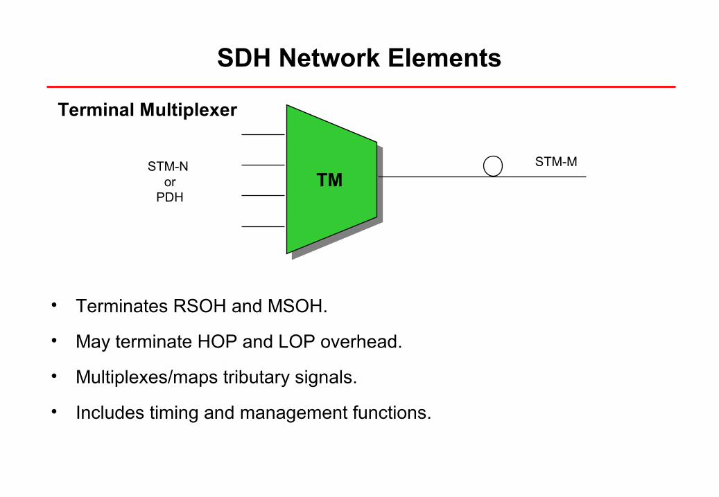
SDH Network Elements
TMSTM-N
orPDH
STM-M
• Terminates RSOH and MSOH.
• May terminate HOP and LOP overhead.
• Multiplexes/maps tributary signals.
• Includes timing and management functions.
Terminal Multiplexer
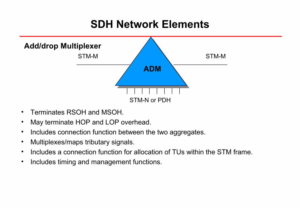
SDH Network Elements
STM-N or PDH
STM-MSTM-M
ADM
• Terminates RSOH and MSOH.• May terminate HOP and LOP overhead.• Includes connection function between the two aggregates.• Multiplexes/maps tributary signals.• Includes a connection function for allocation of TUs within the STM frame. • Includes timing and management functions.
Add/drop Multiplexer
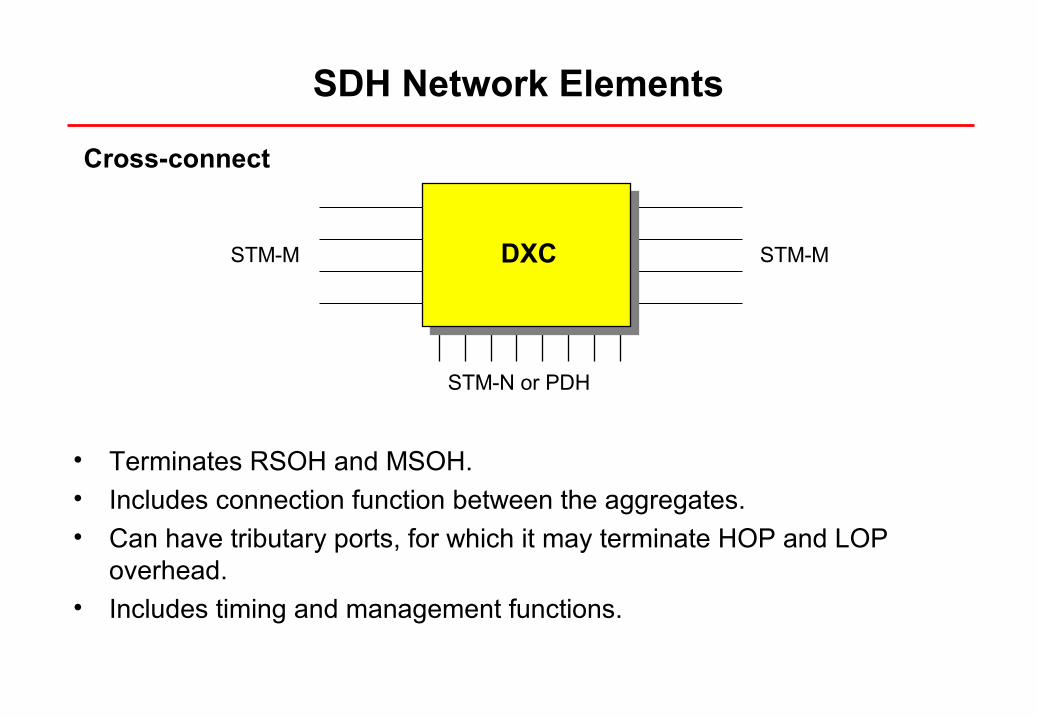
SDH Network Elements
• Terminates RSOH and MSOH.• Includes connection function between the aggregates.• Can have tributary ports, for which it may terminate HOP and LOP
overhead.• Includes timing and management functions.
STM-N or PDH
STM-MSTM-M DXC
Cross-connect
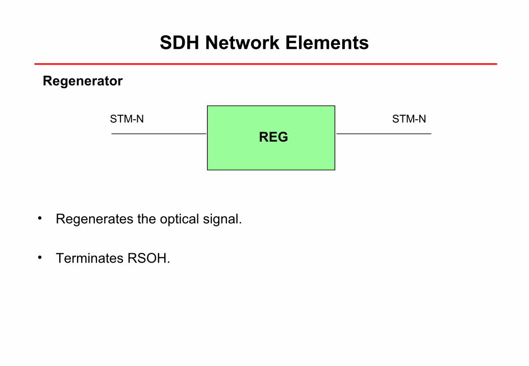
SDH Network Elements
Regenerator
• Regenerates the optical signal.
• Terminates RSOH.
REG
STM-N STM-N
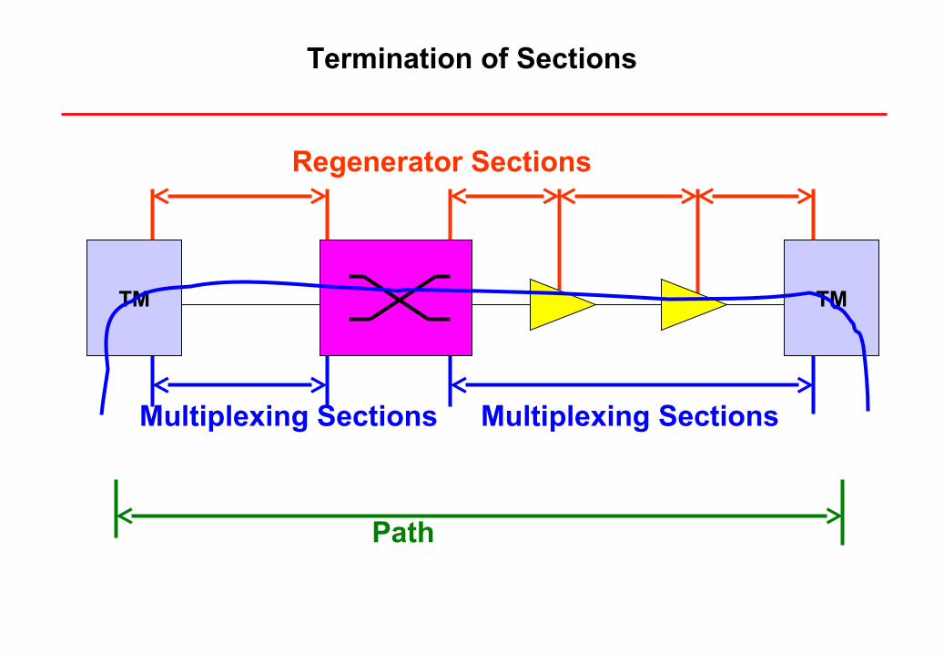
Termination of Sections
Path
Multiplexing Sections Multiplexing Sections
Regenerator Sections
TM TM