Embed Size (px)
Citation preview
A study on Pumps, Motors & Hydraulic Cylinders.
(STATIC TEST RIG FOR RECOIL SYSTEMOF ATAGS)
PARVESH TANEJA | REPORT | 26th MARCH,2017
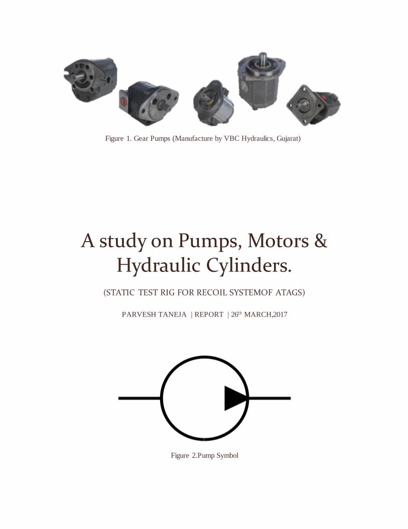
Figure 2.Pump Symbol
Figure 1. Gear Pumps (Manufacture by VBC Hydraulics, Gujarat)
PAGE 1
Contents
1.1 Introduction to Hydraulic Pump ......................................................................................3
1.1.1 Rotodynamic Pump .....................................................................................................3
1.1.1.1 Centrifugal pump ................................................................................................. 3
1.1.2 Reciprocating pump ....................................................................................................4
1.2 Selecting between Centrifugal or Positive Displacement Pumps (Merits & Demerits) ............5
1.2.1 Flow Rate and Pressure Head.......................................................................................5
1.2.2 Capacity and Viscosity ................................................................................................5
1.2.3 Mechanical Efficiency .................................................................................................5
1.2.4 Net Positive Suction Head - NPSH ...............................................................................5
1.3 Terms related to pumps .....................................................................................................6
1.3.1 Static pressure and pressure head .................................................................................6
1.3.1.1 Specific Weight .................................................................................................... 6
1.3.1.2 Static Pressure in a Fluid ..................................................................................... 7
1.3.1.3 The Pressure Head............................................................................................... 8
1.3.2 Fluid Flow Rate ..........................................................................................................9
1.3.3 Pump Lift & Cavitation ............................................................................................. 10
1.3.3.1 Methods to Eliminate (Control) Cavitation .......................................................... 11
1.4 Pump Efficiencies........................................................................................................... 11
1.4.1 Mechanical Efficiency of a Pump (ηm):................................................................... 11
1.4.2 Volumetric Efficiency of a Pump (ηv): .................................................................... 11
1.4.3 Overall Efficiency of a Pump (ηo): ......................................................................... 12
1.5 Pump Selection ............................................................................................................... 12
Classification of different types of pumps............................................................................... 13
PAGE 2
List of Figures
Figure 1. Gear Pumps (Manufacture by VBC Hydraulics, Gujarat) ............................................0
Figure 2.Pump Symbol ...........................................................................................................0
Figure 3.Centrifugal Pump ......................................................................................................3
Figure 4. Reciprocating or positive displacement pump .............................................................4
Figure 5. Gauge Pressure.........................................................................................................8
Figure 6. Flow Rate (Volume) .................................................................................................9
Figure 7. Pump Lift .............................................................................................................. 10
Figure 8. Classification of different types of pumps ................................................................ 13
PAGE 3
1.1 Introduction to Hydraulic Pump
The combined pumping and driving motor unit is known as hydraulic pump. The hydraulic pump
takes hydraulic fluid (mostly some oil) from the storage tank and delivers it to the rest of the
hydraulic circuit. In general, the speed of pump is constant and the pump delivers an equal volume
of oil in each revolution. The amount and direction of fluid flow is controlled by some external
mechanisms. In some cases, the hydraulic pump itself is operated by a servo controlled motor but
it makes the system complex. The hydraulic pumps are characterized by its flow rate capacity,
power consumption, drive speed, pressure delivered at the outlet and efficiency of the pump. The
pumps are not 100% efficient. The efficiency of a pump can be specified by two ways. One is the
volumetric efficiency which is the ratio of actual volume of fluid delivered to the maximum
theoretical volume possible. Second is power efficiency which is the ratio of output hydraulic
power to the input mechanical/electrical power. The typical efficiency of pumps varies from 90-
98%.
Generally, hydraulic pumps can be of two types: • Rotodynamic Pump (Centrifugal Pump) • Reciprocating Pump
1.1.1 Rotodynamic Pump
They have a rotating element (called ‘impeller’) through which when the liquid passes, its angular
momentum changes which results in an increase of the pressure energy of the liquid. Thus, a
rotodynamic pump does not push the liquid as in the case of a positive displacement pump. The
most common example of a rotodynamic pump is centrifugal pumps.
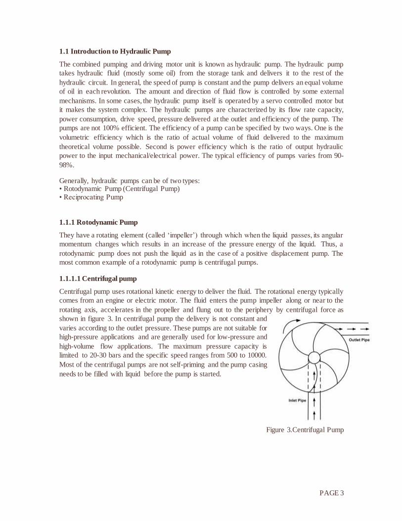
1.1.1.1 Centrifugal pump
Centrifugal pump uses rotational kinetic energy to deliver the fluid. The rotational energy typically
comes from an engine or electric motor. The fluid enters the pump impeller along or near to the
rotating axis, accelerates in the propeller and flung out to the periphery by centrifugal force as
shown in figure 3. In centrifugal pump the delivery is not constant and
varies according to the outlet pressure. These pumps are not suitable for
high-pressure applications and are generally used for low-pressure and
high-volume flow applications. The maximum pressure capacity is
limited to 20-30 bars and the specific speed ranges from 500 to 10000.
Most of the centrifugal pumps are not self-priming and the pump casing
needs to be filled with liquid before the pump is started.
Figure 3.Centrifugal Pump
PAGE 4
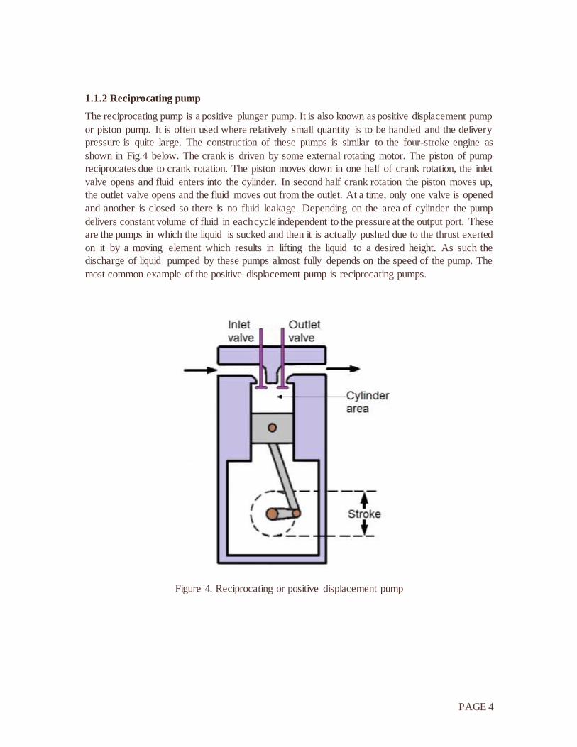
1.1.2 Reciprocating pump
The reciprocating pump is a positive plunger pump. It is also known as positive displacement pump
or piston pump. It is often used where relatively small quantity is to be handled and the delivery
pressure is quite large. The construction of these pumps is similar to the four-stroke engine as
shown in Fig.4 below. The crank is driven by some external rotating motor. The piston of pump
reciprocates due to crank rotation. The piston moves down in one half of crank rotation, the inlet
valve opens and fluid enters into the cylinder. In second half crank rotation the piston moves up,
the outlet valve opens and the fluid moves out from the outlet. At a time, only one valve is opened
and another is closed so there is no fluid leakage. Depending on the area of cylinder the pump
delivers constant volume of fluid in each cycle independent to the pressure at the output port. These
are the pumps in which the liquid is sucked and then it is actually pushed due to the thrust exerted
on it by a moving element which results in lifting the liquid to a desired height. As such the
discharge of liquid pumped by these pumps almost fully depends on the speed of the pump. The
most common example of the positive displacement pump is reciprocating pumps.
Figure 4. Reciprocating or positive displacement pump
PAGE 5
1.2 Selecting between Centrifugal or Positive Displacement Pumps (Merits & Demerits)
1.2.1 Flow Rate and Pressure Head
The two types of pumps behave very differently regarding pressure head and flow rate:
The Centrifugal Pump has varying flow depending on the system pressure or head
The Positive Displacement Pump has more or less a constant flow regardless of the system
pressure or head. Positive Displacement pumps generally makes more pressure than
Centrifugal Pump's.
1.2.2 Capacity and Viscosity
Another major difference between the pump types is the effect of viscosity on capacity:
In a Centrifugal Pump the flow is reduced when the viscosity is increased
In a Positive Displacement Pump the flow is increased when viscosity is increased
Liquids with high viscosity fills the clearances of Positive Displacement Pumps causing higher
volumetric efficiencies and Positive Displacement Pumps are better suited for higher viscosity
applications. A Centrifugal Pump becomes very inefficient at even modest viscosity.
1.2.3 Mechanical Efficiency
The pumps behaves different considering mechanical efficiency as well.
Changing the system pressure or head has little or no effect on the flow rate in a Positive
Displacement Pump
Changing the system pressure or head may have a dramatic effect on the flow rate in a
Centrifugal Pump
1.2.4 Net Positive Suction Head - NPSH
Another consideration is the Net Positive Suction Head - NPSH.
In a Centrifugal Pump, NPSH varies as a function of flow determined by pressure
In a Positive Displacement Pump, NPSH varies as a function of flow determined by speed.
Reducing the speed of the Positive Displacement Pump pump, reduces the NPSH
PAGE 6
1.3 Terms related to pumps
1.3.1 Static pressure and pressure head
Pressure indicates the normal force per unit area at a given point acting on a given plane. Since
there is no shearing stresses present in a fluid at rest - the pressure in a fluid is independent of
direction.
For fluids - liquids or gases - at rest the pressure gradient in the vertical direction depends only on
the specific weight of the fluid.
How pressure changes with elevation can be expressed as
dp = - γ dz (1)
where
dp = change in pressure
dz = change in height
γ = specific weight
The pressure gradient in vertical direction is negative - the pressure decrease upwards.
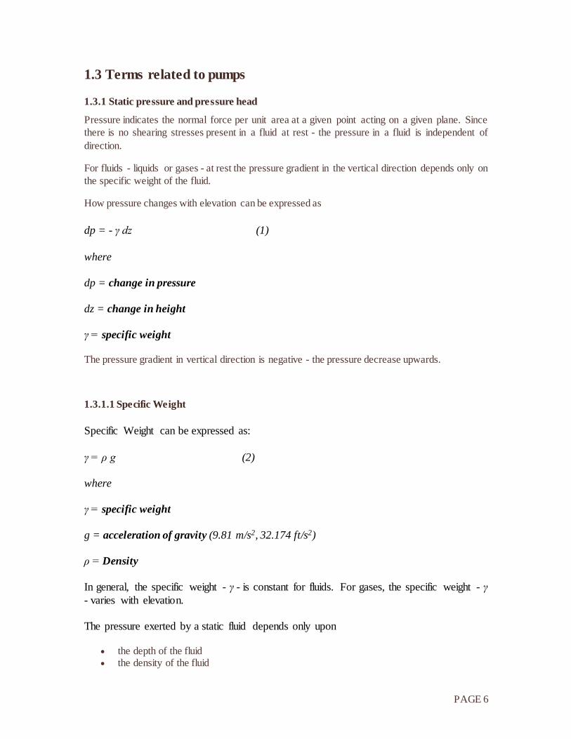
1.3.1.1 Specific Weight
Specific Weight can be expressed as:
γ = ρ g (2)
where
γ = specific weight
g = acceleration of gravity (9.81 m/s2, 32.174 ft/s2)
ρ = Density
In general, the specific weight - γ - is constant for fluids. For gases, the specific weight - γ
- varies with elevation.
The pressure exerted by a static fluid depends only upon
the depth of the fluid the density of the fluid
PAGE 7
the acceleration of gravity
1.3.1.2 Static Pressure in a Fluid
For an incompressible fluid - as a liquid - the pressure difference between two elevations can be expressed as:
p2 - p1 = - γ (z2 - z1) (3)
Where
p2 = pressure at level 2
p1 = pressure at level 1
z2 = level 2
z1 = level 1
(3) can be transformed to:
p1 - p2 = γ (z2 - z1) (4)
or
p1 - p2 = γ h (5)
where
h = z2 - z1 difference in elevation - the depth down from location z2.
or
p1 = γ h + p2 (6)
Example - Pressure in a Fluid
Pressure at water depth of 10 m can be calculated as:
p1 = γ h + p2
= (1000 kg/m3) (9.81 m/s2) (10 m) + (101.3 kPa)
= (98100 kg/ms2 or Pa) + (101300 Pa)
1 atm = 101 kPa = 14.7 psi
PAGE 8
= 199.4 kPa
where
ρ = 1000 kg/m3
g = 9.81 m/s2
p2 = pressure at surface level = atmospheric pressure = 101.3 kPa
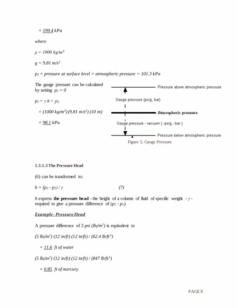
The gauge pressure can be calculated
by setting p2 = 0
p1 = γ h + p2
= (1000 kg/m3) (9.81 m/s2) (10 m)
= 98.1 kPa
1.3.1.3 The Pressure Head
(6) can be transformed to:
h = (p2 - p1) / γ (7)
h express the pressure head - the height of a column of fluid of specific weight - γ - required to give a pressure difference of (p2 - p1).
Example - Pressure Head
A pressure difference of 5 psi (lbf/in2) is equivalent to
(5 lbf/in2) (12 in/ft) (12 in/ft) / (62.4 lb/ft3)
= 11.6 ft of water
(5 lbf/in2) (12 in/ft) (12 in/ft) / (847 lb/ft3)
= 0.85 ft of mercury
Figure 5. Gauge Pressure
PAGE 9
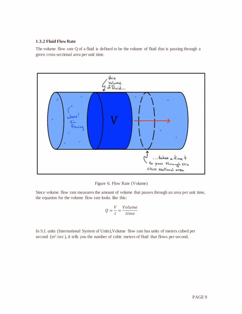
1.3.2 Fluid Flow Rate
The volume flow rate Q of a fluid is defined to be the volume of fluid that is passing through a
given cross sectional area per unit time.
Figure 6. Flow Rate (Volume)
Since volume flow rate measures the amount of volume that passes through an area per unit time,
the equation for the volume flow rate looks like this:
𝑄 =𝑉
𝑡=𝑉𝑜𝑙𝑢𝑚𝑒
𝑡𝑖𝑚𝑒
In S.I. units (International System of Units),Volume flow rate has units of meters cubed per
second (m3 /sec ), it tells you the number of cubic meters of fluid that flows per second.
PAGE 10
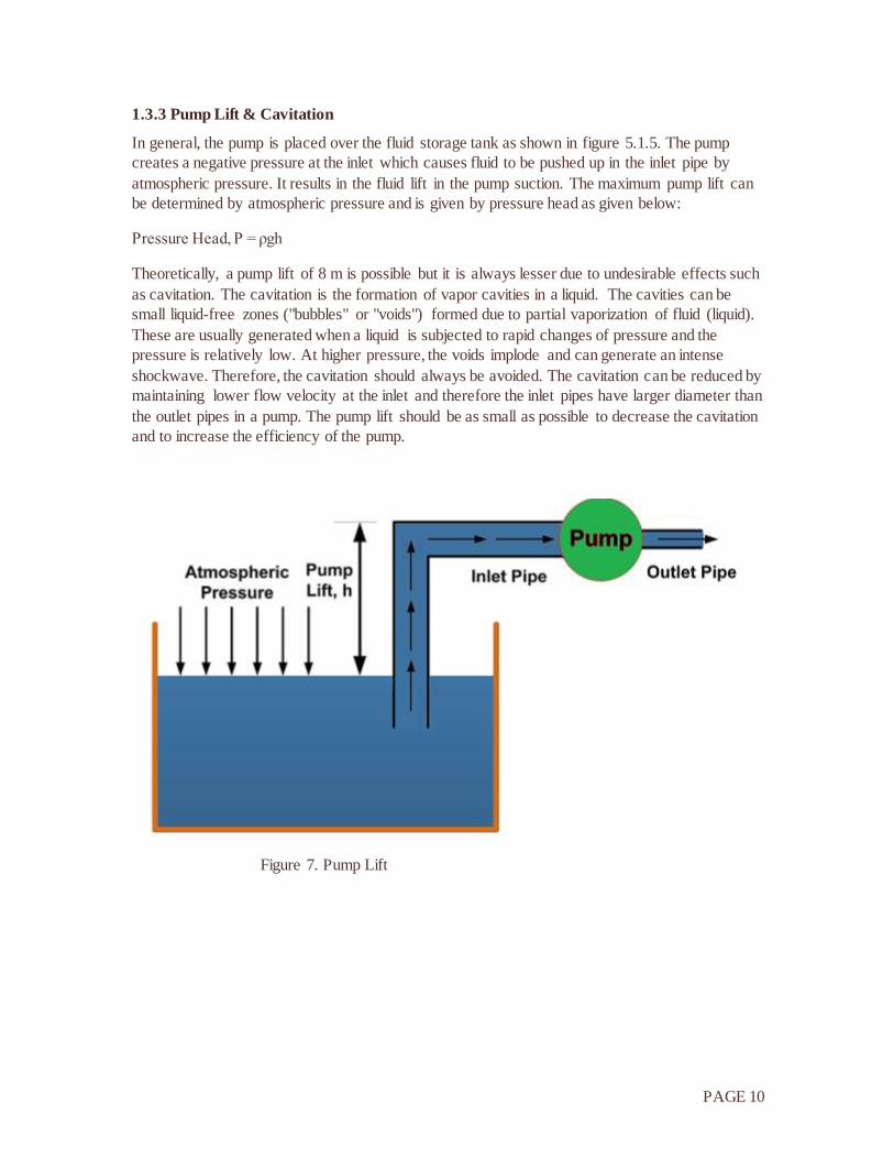
1.3.3 Pump Lift & Cavitation
In general, the pump is placed over the fluid storage tank as shown in figure 5.1.5. The pump
creates a negative pressure at the inlet which causes fluid to be pushed up in the inlet pipe by
atmospheric pressure. It results in the fluid lift in the pump suction. The maximum pump lift can
be determined by atmospheric pressure and is given by pressure head as given below:
Pressure Head, P = ρgh
Theoretically, a pump lift of 8 m is possible but it is always lesser due to undesirable effects such
as cavitation. The cavitation is the formation of vapor cavities in a liquid. The cavities can be
small liquid-free zones ("bubbles" or "voids") formed due to partial vaporization of fluid (liquid).
These are usually generated when a liquid is subjected to rapid changes of pressure and the
pressure is relatively low. At higher pressure, the voids implode and can generate an intense
shockwave. Therefore, the cavitation should always be avoided. The cavitation can be reduced by
maintaining lower flow velocity at the inlet and therefore the inlet pipes have larger diameter than
the outlet pipes in a pump. The pump lift should be as small as possible to decrease the cavitation
and to increase the efficiency of the pump.
Figure 7. Pump Lift
PAGE 11
1.3.3.1 Methods to Eliminate (Control) Cavitation
Following are the methods to control cavitation:
1. Keep suction line velocities below 1.2 m/s.
2. Keep the pump inlet lines as short as possible.
3. Minimize the number of fittings in the inlet line.
4. Mount the pump as close as possible to the reservoir.
5. Use low-pressure drop inlet filters.
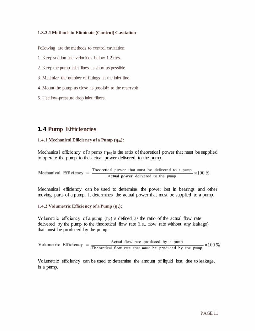
1.4 Pump Efficiencies
1.4.1 Mechanical Efficiency of a Pump (ηm):
Mechanical efficiency of a pump (ηm) is the ratio of theoretical power that must be supplied to operate the pump to the actual power delivered to the pump.
Mechanical efficiency can be used to determine the power lost in bearings and other moving parts of a pump. It determines the actual power that must be supplied to a pump.
1.4.2 Volumetric Efficiency of a Pump (ηv):
Volumetric efficiency of a pump (ηv) is defined as the ratio of the actual flow rate delivered by the pump to the theoretical flow rate (i.e., flow rate without any leakage) that must be produced by the pump.
Volumetric efficiency can be used to determine the amount of liquid lost, due to leakage,
in a pump.
PAGE 12
1.4.3 Overall Efficiency of a Pump (ηo):
Overall efficiency of a pump (ηo) is the ratio of the actual power output of a pump to the actual power input to the pump. It is the efficiency that determines the overall energy loss in a pump.
Overall efficiency is essentially a combination of volumetric efficiency and mechanical efficiency. It is the product of volumetric efficiency and mechanical efficiency of a
pump.
Overall efficiency = Mechanical Efficiency × Volumetric Efficiency
ηo = ηm × ηv
1.5 Pump Selection
Following parameters should be kept in mind while selecting a pump:
1. Maximum operating pressure
2. Maximum delivery
3. Type of control
4. Pump drive speed
5. Type of fluid
6. Pump contamination tolerance
7. Pump noise
8. Size and weight of a pump
9. Pump efficiency
10. Cost
11. Availability and interchangeability
12. Maintenance and spares
.
PAGE 13
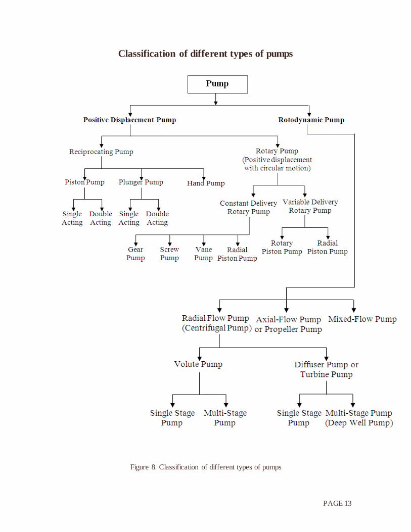
Classification of different types of pumps
Figure 8. Classification of different types of pumps


![NORTA MIT PRESENTATION.pptx [Read-Only] · • Centrifugal pumps • Side channel pumps • Gear pumps • Screw pumps • Single screw pumps • Piston pumps • Vacuum pumps •](https://img.pdfslide.us/doc/110x75/5ec27ab9e3ef591d10504c3a/norta-mit-read-only-a-centrifugal-pumps-a-side-channel-pumps-a-gear-pumps.jpg)


![HPL Report on Pumps in IOP by Subham Shit [Final]](https://img.pdfslide.us/doc/110x75/55d1f20cbb61eb772c8b462b/hpl-report-on-pumps-in-iop-by-subham-shit-final.jpg)