Embed Size (px)
Citation preview
1
Mechanical Properties of Concrete and Steel
Reinforced Concrete (RC, also called RCC for Reinforced Cement Concrete) is a widely used construction material in
many parts the world. Due to the ready availability of its constituent materials, the strength and economy it provides
and the flexibility of its forms, RC is often preferred to steel, masonry or timber in building structures. From a
structural analysis and design point of view, RC is a complex composite material. It provides a unique coupling of two
materials (concrete, steel) with entirely different mechanical properties.
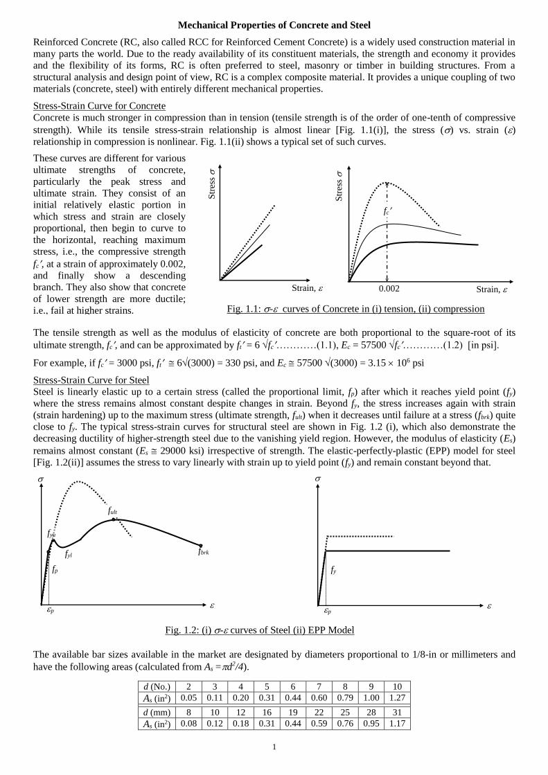
Stress-Strain Curve for Concrete
Concrete is much stronger in compression than in tension (tensile strength is of the order of one-tenth of compressive
strength). While its tensile stress-strain relationship is almost linear [Fig. 1.1(i)], the stress () vs. strain () relationship in compression is nonlinear. Fig. 1.1(ii) shows a typical set of such curves.
The tensile strength as well as the modulus of elasticity of concrete are both proportional to the square-root of its
ultimate strength, fc, and can be approximated by ft = 6 fc…………(1.1), Ec = 57500 fc…………(1.2) [in psi].
For example, if fc = 3000 psi, ft 6(3000) = 330 psi, and Ec 57500 (3000) = 3.15 106 psi
Stress-Strain Curve for Steel
Steel is linearly elastic up to a certain stress (called the proportional limit, fp) after which it reaches yield point (fy)
where the stress remains almost constant despite changes in strain. Beyond fy, the stress increases again with strain
(strain hardening) up to the maximum stress (ultimate strength, fult) when it decreases until failure at a stress (fbrk) quite
close to fy. The typical stress-strain curves for structural steel are shown in Fig. 1.2 (i), which also demonstrate the
decreasing ductility of higher-strength steel due to the vanishing yield region. However, the modulus of elasticity (Es)
remains almost constant (Es 29000 ksi) irrespective of strength. The elastic-perfectly-plastic (EPP) model for steel
[Fig. 1.2(ii)] assumes the stress to vary linearly with strain up to yield point (fy) and remain constant beyond that.
The available bar sizes available in the market are designated by diameters proportional to 1/8-in or millimeters and
have the following areas (calculated from As =d2/4).
d (No.) 2 3 4 5 6 7 8 9 10
As (in2) 0.05 0.11 0.20 0.31 0.44 0.60 0.79 1.00 1.27
d (mm) 8 10 12 16 19 22 25 28 31
As (in2) 0.08 0.12 0.18 0.31 0.44 0.59 0.76 0.95 1.17
These curves are different for various
ultimate strengths of concrete,
particularly the peak stress and
ultimate strain. They consist of an
initial relatively elastic portion in
which stress and strain are closely
proportional, then begin to curve to
the horizontal, reaching maximum
stress, i.e., the compressive strength
fc, at a strain of approximately 0.002,
and finally show a descending
branch. They also show that concrete
of lower strength are more ductile;
i.e., fail at higher strains.
Str
ess
Strain,
Str
ess
Strain, 0.002
fc
Fig. 1.1: - curves of Concrete in (i) tension, (ii) compression
fbrk
fp
p
fyu
fyl
fult
Fig. 1.2: (i) - curves of Steel (ii) EPP Model
fy
p
2
Reinforced Concrete subjected to Axial Force
As Reinforced Concrete (RC) is a complex composite, its structural analysis and design is somewhat different from
homogeneous sections. This is valid if it is subjected to axial force (compression/tension) or bending moment.
Axial Compression
When axial (compressive) force is applied, the compressive strain is the same over the entire cross-section and in view
of the bonding between concrete and steel, is the same in the two materials. Both concrete and steel behave nearly
elastically at low stresses; i.e., which are proportional to strain (corresponding to concrete strain of 0.0003~0.00045
and steel strain of 0.0012~0.0025). Since the stains are equal at a particular point,
c = fc/Ec is equal to s = fs/Es fs = (Es/Ec) fc = n fc ……..…...………………………....(2.1)
where n = Es/Ec, is called the modular ratio.
If As = Area of reinforcing bars, Ac = Net area of concrete; i.e., gross area minus As, Pc = Axial (compressive) load
Pc = fc Ac + fs As= fc (Ac + n As) = fc [Ag+ (n 1) As] ……..…...………………………....(2.2)
To use the basic equations of equilibrium, the structural analysis of RC sections assumes them to be made of a
homogeneous material. Instead of changing the modulus of elasticity over the section, the width of various parts is
modified proportionately. The stress analysis is made of an Equivalent or Transformed Section.
Such an analogy cannot be drawn if the concrete exceeds its elastic limit. However, one quantity of particular interest
to the structural designer is the ultimate strength, the maximum load which the structure or member will carry. Tests
(at different loading conditions and rates) have shown that concrete and steel can be assumed to carry maximum
stresses of 0.85fc and fy under all circumstances. So the ultimate (nominal) load that the member can safely carry is
Pn = 0.85fc Ac + fy As ……..…...…………………………(2.3)
Axial Tension
When the tensile force on a member is small enough for the stress in concrete to be considerably below its tensile
strength (ft), both concrete and steel behave elastically. In this situation, all the expressions derived for compression
are also valid for tension. In particular, the axial force Pc in the earlier equations is now replaced by Pt; i.e.,
Pt = ft [Ag+ (n 1) As] ……..…...………………………....(2.4)
However, when the load is further increased, concrete reaches its tensile strength and ceases to resist any part of the
applied tensile force. So steel is required to resist the entire tensile force. Therefore, at this stage
Pt = fs As, and the ultimate tensile force Pnt = fy As ……..…...………………………....(2.5)
Example 2.1
(a) Calculate the ultimate (nominal) compression and tensile force capacity of the RC section shown below.
(b) Also calculate the stresses in concrete and steel when the section is subjected to
(i) one-tenth its ultimate load, (ii) one-half its ultimate load [Given: fc = 3 ksi, fy = 60 ksi].
2.5
2.5
10
(a) Eq. (2.3) Pn = 0.85fc Ac + fy As= 0.85 3 118.24 + 60 1.76 = 301.51 + 105.60 = 407.11 kips
while Eq. (2.5) Pnt = fy As= 60 1.76 = 105.60 kips
(b) (i) If Pc = Pn/10 = 40.71 k, Pc = fc [Ag+ (n1)As] 40.71 = fc [120 +(91)1.76] fc = 0.304 ksi, fs = nfc = 2.73 ksi
If Pt = Pnt/10 = 10.56 k, Pt = ft [Ag+ (n1)As] 10.56 = ft [120 +(91)1.76] ft = 0.079 ksi, fs = nfc = 0.71 ksi
They correspond to strains of c = s = 2.73/29000 = 9.42 10-5 and s = 0.71/29000 = 2.44 10-5
(ii) If Pc = Pn/2 = 203.56 k fc = 1.52 ksi, fs = 13.66 ksi c = 13.66/29000 = 4.71 10-4
If Pt = Pnt/2 = 52.80 k ft = 0.394 ksi, fs = 3.54 ksi t = 3.54/29000 = 1.22 10-4
Both are inappropriate, as concrete will not be elastic up to c = 4.71 10-4, or uncracked up to t = 1.22 10-4
A ‘cracked’ section will give ft = 0 ksi, fs = 30 ksi, while iterations will be needed to obtain appropriate fc and fs
2 #6 Bars
2 #6 Bars
7
For fc = 3 ksi = 3000 psi, the tensile strength and modulus
of elasticity of concrete are approximated by
ft = 6fc = 6(3000) = 330 psi
Ec = 57500fc = 57500(3000) = 3.15 106 psi
If Es = 29 106 psi, Modular ratio, n = Es/Ec 9
Also Ag = 10 12 = 120 in2, As = 4 0.44 = 1.76 in2
Ac = 120 1.76 = 118.24 in2
3
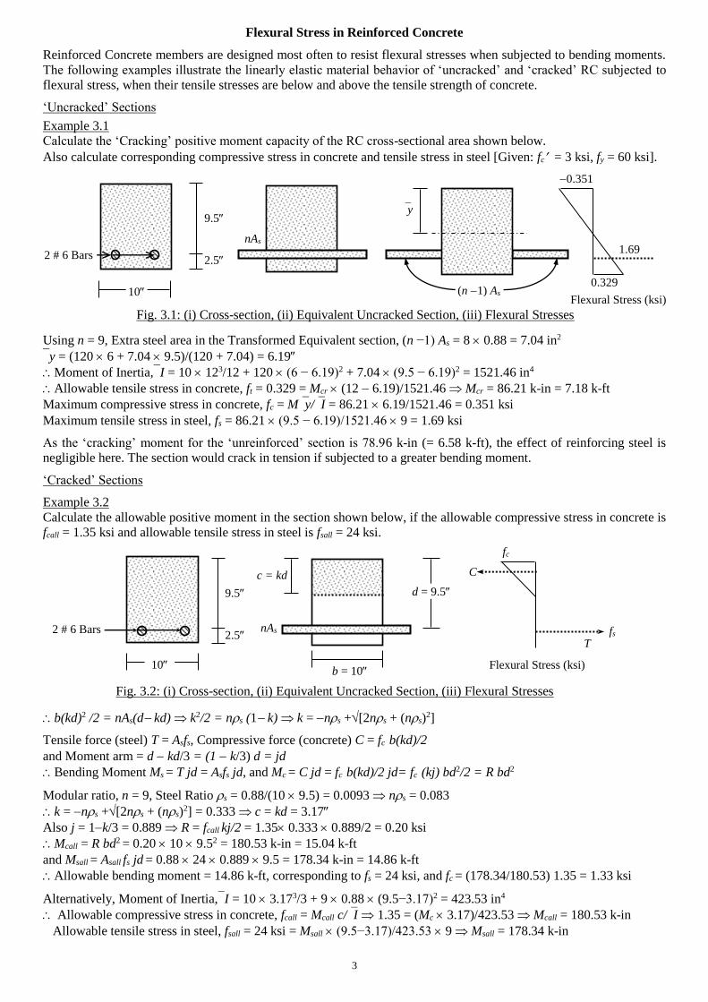
Flexural Stress in Reinforced Concrete
Reinforced Concrete members are designed most often to resist flexural stresses when subjected to bending moments.
The following examples illustrate the linearly elastic material behavior of ‘uncracked’ and ‘cracked’ RC subjected to
flexural stress, when their tensile stresses are below and above the tensile strength of concrete.
‘Uncracked’ Sections
Example 3.1
Calculate the ‘Cracking’ positive moment capacity of the RC cross-sectional area shown below.
Also calculate corresponding compressive stress in concrete and tensile stress in steel [Given: fc = 3 ksi, fy = 60 ksi].
9.5
2.5
Using n = 9, Extra steel area in the Transformed Equivalent section, (n −1) As = 8 0.88 = 7.04 in2
y = (120 6 + 7.04 9.5)/(120 + 7.04) = 6.19
Moment of Inertia,I = 10 123/12 + 120 (6 − 6.19)2 + 7.04 (9.5 − 6.19)2 = 1521.46 in4
Allowable tensile stress in concrete, ft = 0.329 = Mcr (12 6.19)/1521.46 Mcr = 86.21 k-in = 7.18 k-ft
Maximum compressive stress in concrete, fc = My/I = 86.21 6.19/1521.46 = 0.351 ksi
Maximum tensile stress in steel, fs = 86.21 (9.5 − 6.19)/1521.46 9 = 1.69 ksi
As the ‘cracking’ moment for the ‘unreinforced’ section is 78.96 k-in (= 6.58 k-ft), the effect of reinforcing steel is
negligible here. The section would crack in tension if subjected to a greater bending moment.
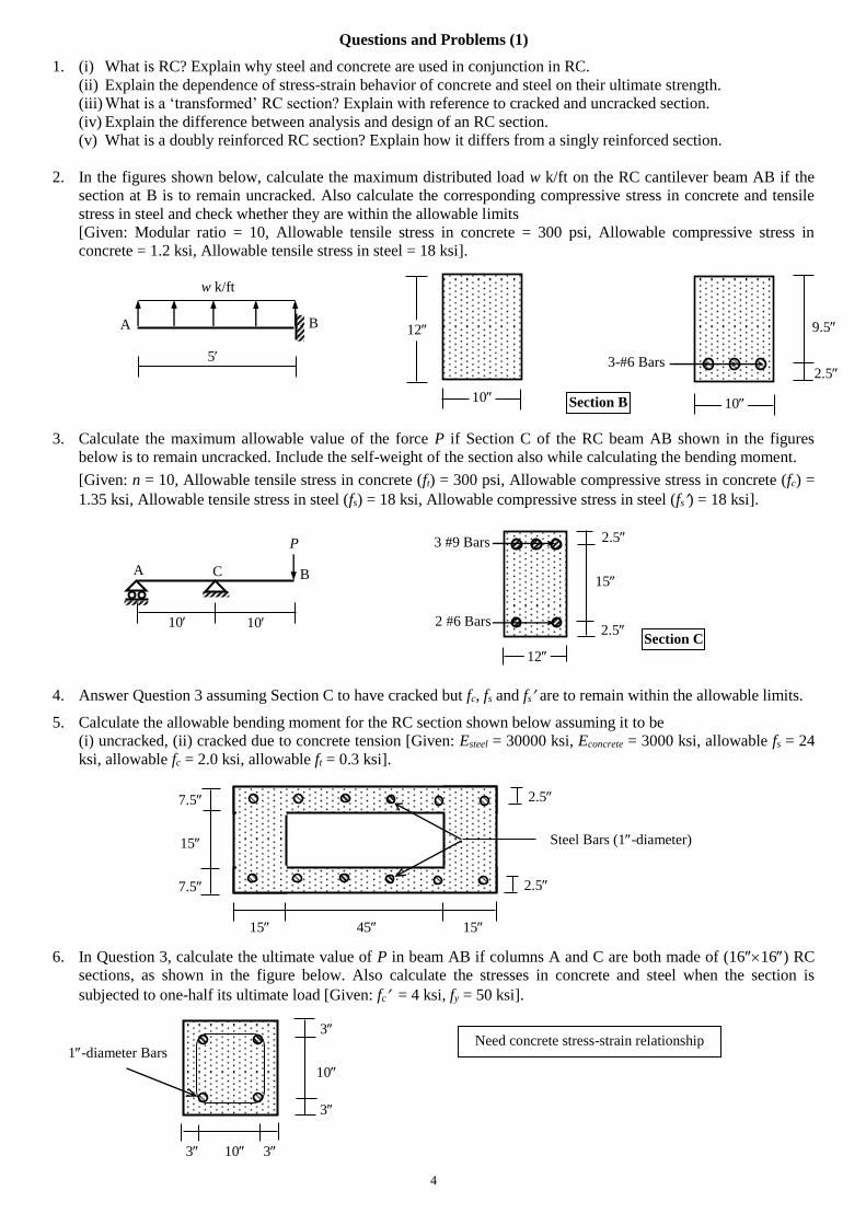
‘Cracked’ Sections
Example 3.2
Calculate the allowable positive moment in the section shown below, if the allowable compressive stress in concrete is
fcall = 1.35 ksi and allowable tensile stress in steel is fsall = 24 ksi.
b(kd)2 /2 = nAs(d kd) k2/2 = ns (1 k) k = ns +[2ns + (ns)2]
Tensile force (steel) T = Asfs, Compressive force (concrete) C = fc b(kd)/2
and Moment arm = d kd/3 = (1 k/3) d = jd
Bending Moment Ms = T jd = Asfs jd, and Mc = C jd = fc b(kd)/2 jd= fc (kj) bd2/2 = R bd2
Modular ratio, n = 9, Steel Ratio s = 0.88/(10 9.5) = 0.0093 ns = 0.083
k = ns +[2ns + (ns)2] = 0.333 c = kd = 3.17
Also j = 1k/3 = 0.889 R = fcall kj/2 = 1.35 0.333 0.889/2 = 0.20 ksi
Mcall = R bd2 = 0.20 10 9.52 = 180.53 k-in = 15.04 k-ft
and Msall = Asall fs jd = 0.88 24 0.889 9.5 = 178.34 k-in = 14.86 k-ft
Allowable bending moment = 14.86 k-ft, corresponding to fs = 24 ksi, and fc = (178.34/180.53) 1.35 = 1.33 ksi
Alternatively, Moment of Inertia,I = 10 3.173/3 + 9 0.88 (9.5−3.17)2 = 423.53 in4
Allowable compressive stress in concrete, fcall = Mcall c/I 1.35 = (Mc 3.17)/423.53 Mcall = 180.53 k-in
Allowable tensile stress in steel, fsall = 24 ksi = Msall (9.5−3.17)/423.53 9 Msall = 178.34 k-in
b = 10
9.5
2.5
d = 9.5
10
nAs
c = kd
Fig. 3.1: (i) Cross-section, (ii) Equivalent Uncracked Section, (iii) Flexural Stresses
nAs
(n 1) As
y
0.329
0.351
Flexural Stress (ksi)
1.69
Flexural Stress (ksi)
fs
2 # 6 Bars
10
2 # 6 Bars
fc
C
T
Fig. 3.2: (i) Cross-section, (ii) Equivalent Uncracked Section, (iii) Flexural Stresses
4
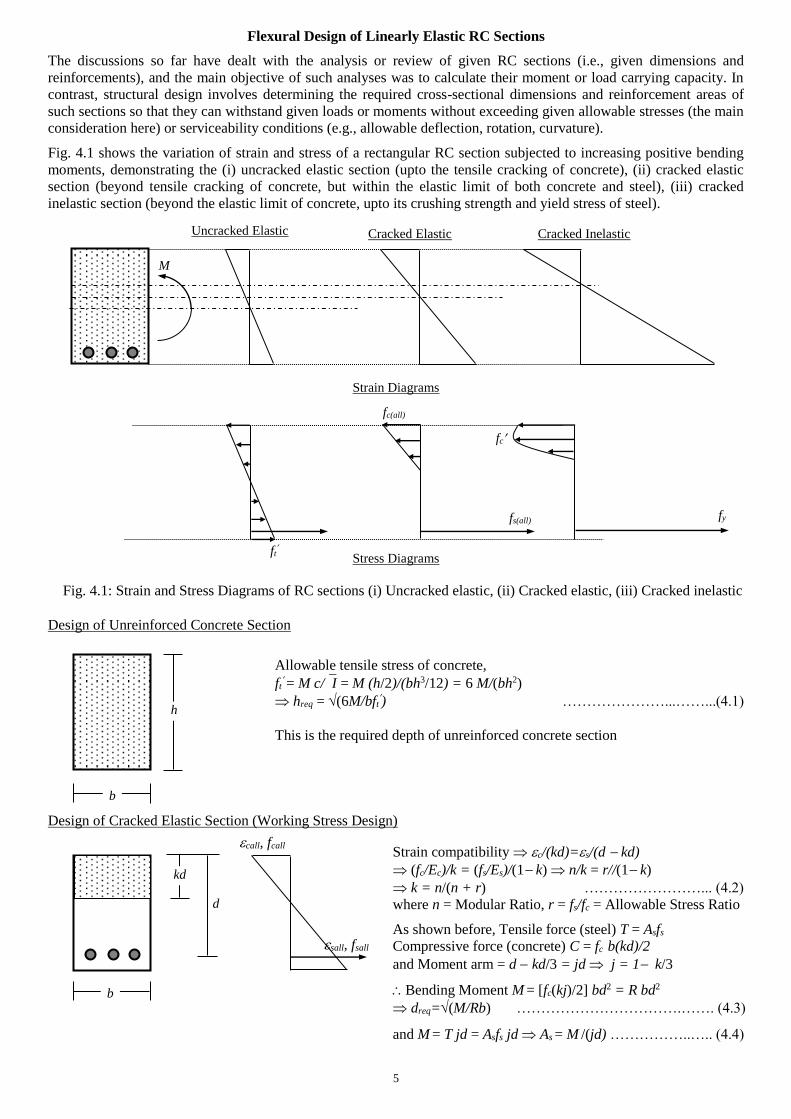
Questions and Problems (1)
1. (i) What is RC? Explain why steel and concrete are used in conjunction in RC.
(ii) Explain the dependence of stress-strain behavior of concrete and steel on their ultimate strength.
(iii) What is a ‘transformed’ RC section? Explain with reference to cracked and uncracked section.
(iv) Explain the difference between analysis and design of an RC section.
(v) What is a doubly reinforced RC section? Explain how it differs from a singly reinforced section.
2. In the figures shown below, calculate the maximum distributed load w k/ft on the RC cantilever beam AB if the
section at B is to remain uncracked. Also calculate the corresponding compressive stress in concrete and tensile
stress in steel and check whether they are within the allowable limits
[Given: Modular ratio = 10, Allowable tensile stress in concrete = 300 psi, Allowable compressive stress in
concrete = 1.2 ksi, Allowable tensile stress in steel = 18 ksi].
3. Calculate the maximum allowable value of the force P if Section C of the RC beam AB shown in the figures
below is to remain uncracked. Include the self-weight of the section also while calculating the bending moment.
[Given: n = 10, Allowable tensile stress in concrete (ft) = 300 psi, Allowable compressive stress in concrete (fc) =
1.35 ksi, Allowable tensile stress in steel (fs) = 18 ksi, Allowable compressive stress in steel (fs) = 18 ksi].
4. Answer Question 3 assuming Section C to have cracked but fc, fs and fs are to remain within the allowable limits.
5. Calculate the allowable bending moment for the RC section shown below assuming it to be
(i) uncracked, (ii) cracked due to concrete tension [Given: Esteel = 30000 ksi, Econcrete = 3000 ksi, allowable fs = 24
ksi, allowable fc = 2.0 ksi, allowable ft = 0.3 ksi].
6. In Question 3, calculate the ultimate value of P in beam AB if columns A and C are both made of (1616) RC
sections, as shown in the figure below. Also calculate the stresses in concrete and steel when the section is
subjected to one-half its ultimate load [Given: fc = 4 ksi, fy = 50 ksi].
15 45 15
5
A B
w k/ft
Section B
10
A B
P
12
15
Section C
C
10
2.5
2.5
3 #9 Bars
2 #6 Bars
Steel Bars (1-diameter)
7.5
15
7.5
2.5
2.5
10
9.5
2.5 3-#6 Bars
10
12
3
10
3
3 10 3
1-diameter Bars Need concrete stress-strain relationship
5
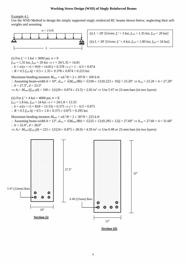
Flexural Design of Linearly Elastic RC Sections
The discussions so far have dealt with the analysis or review of given RC sections (i.e., given dimensions and
reinforcements), and the main objective of such analyses was to calculate their moment or load carrying capacity. In
contrast, structural design involves determining the required cross-sectional dimensions and reinforcement areas of
such sections so that they can withstand given loads or moments without exceeding given allowable stresses (the main
consideration here) or serviceability conditions (e.g., allowable deflection, rotation, curvature).
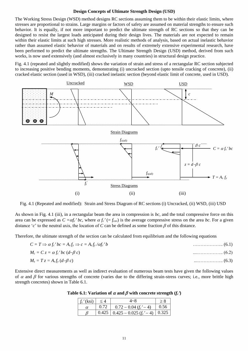
Fig. 4.1 shows the variation of strain and stress of a rectangular RC section subjected to increasing positive bending
moments, demonstrating the (i) uncracked elastic section (upto the tensile cracking of concrete), (ii) cracked elastic
section (beyond tensile cracking of concrete, but within the elastic limit of both concrete and steel), (iii) cracked
inelastic section (beyond the elastic limit of concrete, upto its crushing strength and yield stress of steel).
Strain Diagrams
Stress Diagrams
Design of Unreinforced Concrete Section
Design of Cracked Elastic Section (Working Stress Design)
call, fcall
sall, fsall
Uncracked Elastic Cracked Elastic Cracked Inelastic
Fig. 4.1: Strain and Stress Diagrams of RC sections (i) Uncracked elastic, (ii) Cracked elastic, (iii) Cracked inelastic
M
ft
fc(all)
fs(all) fy
fc
Strain compatibility c/(kd)=s/(d kd)
(fc/Ec)/k = (fs/Es)/(1 k) n/k = r//(1 k)
k = n/(n + r) ……………………... (4.2)
where n = Modular Ratio, r = fs/fc = Allowable Stress Ratio
As shown before, Tensile force (steel) T = Asfs
Compressive force (concrete) C = fc b(kd)/2
and Moment arm = d kd/3 = jd j = 1 k/3
Bending Moment M = [fc(kj)/2] bd2 = R bd2
dreq=(M/Rb) …………………………….……. (4.3)
and M = T jd = Asfs jd As = M /(jd) ……………..….. (4.4)
b
d
Allowable tensile stress of concrete,
ft = M c/I = M (h/2)/(bh3/12) = 6 M/(bh2)
hreq = (6M/bft) …………………...……...(4.1)
This is the required depth of unreinforced concrete section
b
h
kd
6
Working Stress Design (WSD) of Singly Reinforced Beams
Example 4.1
Use the WSD Method to design the simply supported singly reinforced RC beams shown below, neglecting their self-
weights and assuming
(i) For fc = 3 ksi = 3000 psi, n = 9
fcall = 1.35 ksi, fsall = 20 ksi r = 20/1.35 = 14.81
k = n/(n + r) = 9/(9 + 14.81) = 0.378 j = 1 k/3 = 0.874
R = 0.5 fcall kj = 0.5 1.35 0.378 0.874 = 0.223 ksi
Maximum bending moment Mmax = wL2/8 = 2 202/8 = 100 k-ft
Assuming beam-width b = 10, dreq = (Mmax/Rb) = [100 12/(0.223 10)] = 23.20 hreq = 23.20 + 4 = 27.20
h = 27.5, d = 23.5
As= Mmax/(fsall jd) = 100 12/(20 0.874 23.5) = 2.92 in2 Use 5 #7 or 22-mm bars (in two layers)
(ii) For fc = 4 ksi = 4000 psi, n = 8
fcall = 1.8 ksi, fsall = 24 ksi r = 24/1.8 = 13.33
k = n/(n + r) = 8/(8 + 13.33) = 0.375 j = 1 k/3 = 0.875
R = 0.5 fcall kj = 0.5 1.8 0.375 0.875 = 0.295 ksi
Maximum bending moment Mmax = wL2/8 = 2 302/8 = 225 k-ft
Assuming beam-width b = 12, dreq = (Mmax/Rb) = [225 12/(0.295 12)] = 27.60 hreq = 27.60 + 4 = 31.60
h = 32.0, d = 28.0
As= Mmax/(fsall jd) = 225 12/(24 0.875 28.0) = 4.59 in2 Use 6 #8 or 25-mm bars (in two layers)
27.5
32
10
Section (i) 12
Section (ii)
L
w = 2 k/ft (i) L = 20 [Given: fc = 3 ksi, fcall = 1.35 ksi, fsall = 20 ksi]
(ii) L = 30 [Given: fc = 4 ksi, fcall = 1.80 ksi, fsall = 24 ksi]
5 #7 (22mm) Bars
6 #8 (25mm) Bars
7
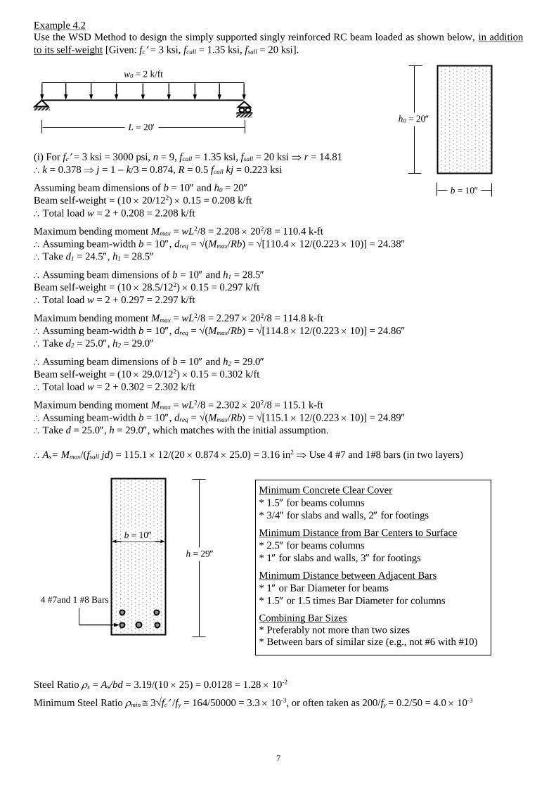
Example 4.2
Use the WSD Method to design the simply supported singly reinforced RC beam loaded as shown below, in addition
to its self-weight [Given: fc = 3 ksi, fcall = 1.35 ksi, fsall = 20 ksi].
(i) For fc = 3 ksi = 3000 psi, n = 9, fcall = 1.35 ksi, fsall = 20 ksi r = 14.81
k = 0.378 j = 1 k/3 = 0.874, R = 0.5 fcall kj = 0.223 ksi
Assuming beam dimensions of b = 10 and h0 = 20
Beam self-weight = (10 20/122) 0.15 = 0.208 k/ft
Total load w = 2 + 0.208 = 2.208 k/ft
Maximum bending moment Mmax = wL2/8 = 2.208 202/8 = 110.4 k-ft
Assuming beam-width b = 10, dreq = (Mmax/Rb) = [110.4 12/(0.223 10)] = 24.38
Take d1 = 24.5, h1 = 28.5
Assuming beam dimensions of b = 10 and h1 = 28.5
Beam self-weight = (10 28.5/122) 0.15 = 0.297 k/ft
Total load w = 2 + 0.297 = 2.297 k/ft
Maximum bending moment Mmax = wL2/8 = 2.297 202/8 = 114.8 k-ft
Assuming beam-width b = 10, dreq = (Mmax/Rb) = [114.8 12/(0.223 10)] = 24.86
Take d2 = 25.0, h2 = 29.0
Assuming beam dimensions of b = 10 and h2 = 29.0
Beam self-weight = (10 29.0/122) 0.15 = 0.302 k/ft
Total load w = 2 + 0.302 = 2.302 k/ft
Maximum bending moment Mmax = wL2/8 = 2.302 202/8 = 115.1 k-ft
Assuming beam-width b = 10, dreq = (Mmax/Rb) = [115.1 12/(0.223 10)] = 24.89
Take d = 25.0, h = 29.0, which matches with the initial assumption.
As= Mmax/(fsall jd) = 115.1 12/(20 0.874 25.0) = 3.16 in2 Use 4 #7 and 1#8 bars (in two layers)
Steel Ratio s = As/bd = 3.19/(10 25) = 0.0128 = 1.28 10-2
Minimum Steel Ratio min 3fc /fy = 164/50000 = 3.3 10-3, or often taken as 200/fy = 0.2/50 = 4.0 10-3
L = 20
w0 = 2 k/ft
h0 = 20
b = 10
4 #7and 1 #8 Bars
b = 10
h = 29
Minimum Concrete Clear Cover
* 1.5 for beams columns
* 3/4 for slabs and walls, 2 for footings
Minimum Distance from Bar Centers to Surface
* 2.5 for beams columns
* 1 for slabs and walls, 3 for footings
Minimum Distance between Adjacent Bars
* 1 or Bar Diameter for beams
* 1.5 or 1.5 times Bar Diameter for columns
Combining Bar Sizes
* Preferably not more than two sizes
* Between bars of similar size (e.g., not #6 with #10)
8
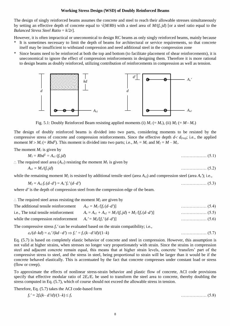
Working Stress Design (WSD) of Doubly Reinforced Beams
The design of singly reinforced beams assumes the concrete and steel to reach their allowable stresses simultaneously
by setting an effective depth of concrete equal to (M/Rb) with a steel area of M/(fs jd) [or a steel ratio equal to the
Balanced Stress Steel Ratio = k/2r].
However, it is often impractical or uneconomical to design RC beams as only singly reinforced beams, mainly because
* It is sometimes necessary to limit the depth of beams for architectural or service requirements, so that concrete
itself may be insufficient to withstand compression and need additional steel in the compression zone
* Since beams need to be reinforced at both the top and bottom (to facilitate placement of shear reinforcements), it is
uneconomical to ignore the effect of compression reinforcements in designing them. Therefore it is more rational
to design beams as doubly reinforced, utilizing contribution of reinforcements in compression as well as tension.
The design of doubly reinforced beams is divided into two parts, considering moments to be resisted by the
compressive stress of concrete and compression reinforcements. Since the effective depth d d(req); i.e., the applied
moment M Mc (= Rbd2). This moment is divided into two parts; i.e., M1 = Mc and M2 = M – Mc.
The moment M1 is given by
M1 = Rbd2 = As1 (fs jd) ……………… (5.1)
The required steel area (As1) resisting the moment M1 is given by
As1 = M1/(fs jd) ……………… (5.2)
while the remaining moment M2 is resisted by additional tensile steel (area As2) and compression steel (area As); i.e.,
M2 = As2 fs (d–d) = As fs (d–d) ……………… (5.3)
where d is the depth of compression steel from the compression edge of the beam.
The required steel areas resisting the moment M2 are given by
The additional tensile reinforcement As2 = M2 /[fs (d–d)] ……………… (5.4)
i.e., The total tensile reinforcement As = As1 + As2 = M1/(fs jd) + M2 /[fs (d–d)] ……………… (5.5)
while the compression reinforcement As = M2/[fs (d–d)] ……………… (5.6)
The compressive stress fs can be evaluated based on the strain compatibility; i.e.,
s/(dkd) = s /(kd d) fs = fs (k d/d)/(1k) ……………… (5.7)
Eq. (5.7) is based on completely elastic behavior of concrete and steel in compression. However, this assumption is
not valid at higher strains, when stresses no longer vary proportionately with strain. Since the strains in compression
steel and adjacent concrete remain equal, this means that at higher strain levels, concrete ‘transfers’ part of the
compressive stress to steel, and the stress in steel, being proportional to strain will be larger than it would be if the
concrete behaved elastically. This is accentuated by the fact that concrete compresses under constant load or stress
(flow or creep).
To approximate the effects of nonlinear stress-strain behavior and plastic flow of concrete, ACI code provisions
specify that effective modular ratio of 2Es/Ec be used to transform the steel area to concrete, thereby doubling the
stress computed in Eq. (5.7), which of course should not exceed the allowable stress in tension.
Therefore, Eq. (5.7) takes the ACI code-based form
fs = 2fs(k– d/d)/(1–k) fs ……………… (5.8)
d
kd
d
d
As1 As2
As
Fig. 5.1: Doubly Reinforced Beam resisting applied moments (i) M1 (= Mc), (ii) M2 (= M Mc)
9
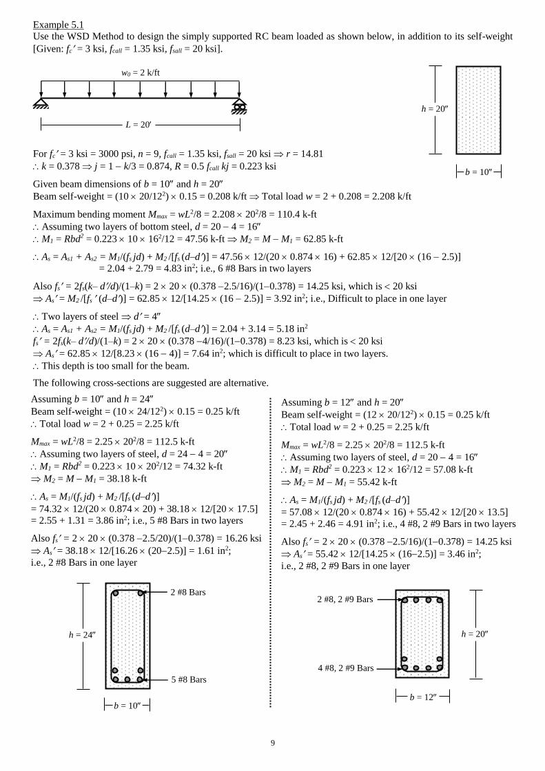
Example 5.1
Use the WSD Method to design the simply supported RC beam loaded as shown below, in addition to its self-weight
[Given: fc = 3 ksi, fcall = 1.35 ksi, fsall = 20 ksi].
For fc = 3 ksi = 3000 psi, n = 9, fcall = 1.35 ksi, fsall = 20 ksi r = 14.81
k = 0.378 j = 1 k/3 = 0.874, R = 0.5 fcall kj = 0.223 ksi
Given beam dimensions of b = 10 and h = 20
Beam self-weight = (10 20/122) 0.15 = 0.208 k/ft Total load w = 2 + 0.208 = 2.208 k/ft
Maximum bending moment Mmax = wL2/8 = 2.208 202/8 = 110.4 k-ft
Assuming two layers of bottom steel, d = 20 4 = 16
M1 = Rbd2 = 0.223 10 162/12 = 47.56 k-ft M2 = M M1 = 62.85 k-ft
As = As1 + As2 = M1/(fs jd) + M2 /[fs (d–d)] = 47.56 12/(20 0.874 16) + 62.85 12/[20 (16 2.5)]
= 2.04 + 2.79 = 4.83 in2; i.e., 6 #8 Bars in two layers
Also fs = 2fs(k– d/d)/(1–k) = 2 20 (0.378 2.5/16)/(10.378) = 14.25 ksi, which is 20 ksi
As = M2 /[fs (d–d)] = 62.85 12/[14.25 (16 2.5)] = 3.92 in2; i.e., Difficult to place in one layer
Two layers of steel d = 4
As = As1 + As2 = M1/(fs jd) + M2 /[fs (d–d)] = 2.04 + 3.14 = 5.18 in2
fs = 2fs(k– d/d)/(1–k) = 2 20 (0.378 4/16)/(10.378) = 8.23 ksi, which is 20 ksi
As = 62.85 12/[8.23 (16 4)] = 7.64 in2; which is difficult to place in two layers.
This depth is too small for the beam.
The following cross-sections are suggested are alternative.
L = 20
w0 = 2 k/ft
h = 20
b = 10
Assuming b = 10 and h = 24
Beam self-weight = (10 24/122) 0.15 = 0.25 k/ft
Total load w = 2 + 0.25 = 2.25 k/ft
Mmax = wL2/8 = 2.25 202/8 = 112.5 k-ft
Assuming two layers of steel, d = 24 4 = 20
M1 = Rbd2 = 0.223 10 202/12 = 74.32 k-ft
M2 = M M1 = 38.18 k-ft
As = M1/(fs jd) + M2 /[fs (d–d)]
= 74.32 12/(20 0.874 20) + 38.18 12/[20 17.5]
= 2.55 + 1.31 = 3.86 in2; i.e., 5 #8 Bars in two layers
Also fs = 2 20 (0.378 2.5/20)/(10.378) = 16.26 ksi
As = 38.18 12/[16.26 (202.5)] = 1.61 in2;
i.e., 2 #8 Bars in one layer
Assuming b = 12 and h = 20
Beam self-weight = (12 20/122) 0.15 = 0.25 k/ft
Total load w = 2 + 0.25 = 2.25 k/ft
Mmax = wL2/8 = 2.25 202/8 = 112.5 k-ft
Assuming two layers of steel, d = 20 4 = 16
M1 = Rbd2 = 0.223 12 162/12 = 57.08 k-ft
M2 = M M1 = 55.42 k-ft
As = M1/(fs jd) + M2 /[fs (d–d)]
= 57.08 12/(20 0.874 16) + 55.42 12/[20 13.5]
= 2.45 + 2.46 = 4.91 in2; i.e., 4 #8, 2 #9 Bars in two layers
Also fs = 2 20 (0.378 2.5/16)/(10.378) = 14.25 ksi
As = 55.42 12/[14.25 (162.5)] = 3.46 in2;
i.e., 2 #8, 2 #9 Bars in one layer
b = 12
h = 20
4 #8, 2 #9 Bars
2 #8, 2 #9 Bars
h = 24
b = 10
5 #8 Bars
2 #8 Bars
10
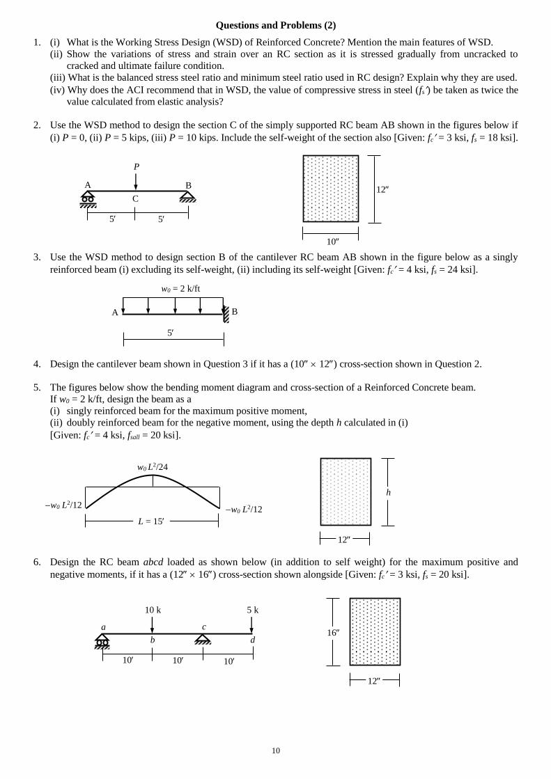
Questions and Problems (2)
1. (i) What is the Working Stress Design (WSD) of Reinforced Concrete? Mention the main features of WSD.
(ii) Show the variations of stress and strain over an RC section as it is stressed gradually from uncracked to
cracked and ultimate failure condition.
(iii) What is the balanced stress steel ratio and minimum steel ratio used in RC design? Explain why they are used.
(iv) Why does the ACI recommend that in WSD, the value of compressive stress in steel (fs) be taken as twice the
value calculated from elastic analysis?
2. Use the WSD method to design the section C of the simply supported RC beam AB shown in the figures below if
(i) P = 0, (ii) P = 5 kips, (iii) P = 10 kips. Include the self-weight of the section also [Given: fc = 3 ksi, fs = 18 ksi].
3. Use the WSD method to design section B of the cantilever RC beam AB shown in the figure below as a singly
reinforced beam (i) excluding its self-weight, (ii) including its self-weight [Given: fc = 4 ksi, fs = 24 ksi].
4. Design the cantilever beam shown in Question 3 if it has a (10 12) cross-section shown in Question 2.
5. The figures below show the bending moment diagram and cross-section of a Reinforced Concrete beam.
If w0 = 2 k/ft, design the beam as a
(i) singly reinforced beam for the maximum positive moment,
(ii) doubly reinforced beam for the negative moment, using the depth h calculated in (i)
[Given: fc = 4 ksi, fsall = 20 ksi].
6. Design the RC beam abcd loaded as shown below (in addition to self weight) for the maximum positive and
negative moments, if it has a (12 16) cross-section shown alongside [Given: fc = 3 ksi, fs = 20 ksi].
B
5
A
w0 = 2 k/ft
5
A B
P
10
12 C
5
12
16
10
a
b
c
10
d
5 k
10
10 k
w0 L2/12
w0 L2/24
L = 15
h
12
w0 L2/12
11
Design Concepts of Ultimate Strength Design (USD)
The Working Stress Design (WSD) method designs RC sections assuming them to be within their elastic limits, where
stresses are proportional to strains. Large margins or factors of safety are assumed on material strengths to ensure such
behavior. It is equally, if not more important to predict the ultimate strength of RC sections so that they can be
designed to resist the largest loads anticipated during their design lives. The materials are not expected to remain
within their elastic limits at such high stresses. More realistic methods of analysis, based on actual inelastic behavior
rather than assumed elastic behavior of materials and on results of extremely extensive experimental research, have
been performed to predict the ultimate strengths. The Ultimate Strength Design (USD) method, derived from such
works, is now used extensively (and almost exclusively in many countries) in structural design practice.
Fig. 4.1 (repeated and slightly modified) shows the variation of strain and stress of a rectangular RC section subjected
to increasing positive bending moments, demonstrating (i) uncracked section (upto tensile cracking of concrete), (ii)
cracked elastic section (used in WSD), (iii) cracked inelastic section (beyond elastic limit of concrete, used in USD).
Strain Diagrams
Stress Diagrams
(i) (ii) (iii)
As shown in Fig. 4.1 (iii), in a rectangular beam the area in compression is bc, and the total compressive force on this
area can be expressed as C =fc bc, where fc (= fcav) is the average compressive stress on the area bc. For a given
distance ‘c’ to the neutral axis, the location of C can be defined as some fraction of this distance.
Therefore, the ultimate strength of the section can be calculated from equilibrium and the following equations
C = T fc bc = As fy c = As fy /fc b ……………….. (6.1)
Mc = C z = fc bc (d c) ....…………….. (6.2)
Ms = T z = As fy (d c) ...…………….. (6.3)
Extensive direct measurements as well as indirect evaluation of numerous beam tests have given the following values
of and for various strengths of concrete (varies due to the differing strain-stress curves; i.e., more brittle high
strength concretes) shown in Table 6.1.
Table 6.1: Variation of and with concrete strength (fc)
fc (ksi) 4 4~8 8
0.72 0.72 0.04 (fc 4) 0.56
0.425 0.425 0.025 (fc 4) 0.325
Uncracked WSD USD
Fig. 4.1 (Repeated and modified): Strain and Stress Diagram of RC sections (i) Uncracked, (ii) WSD, (iii) USD
M
ft
fc(all)
fs(all)
T = As fy
fc
c
c
z = d c
C = fc bc
12
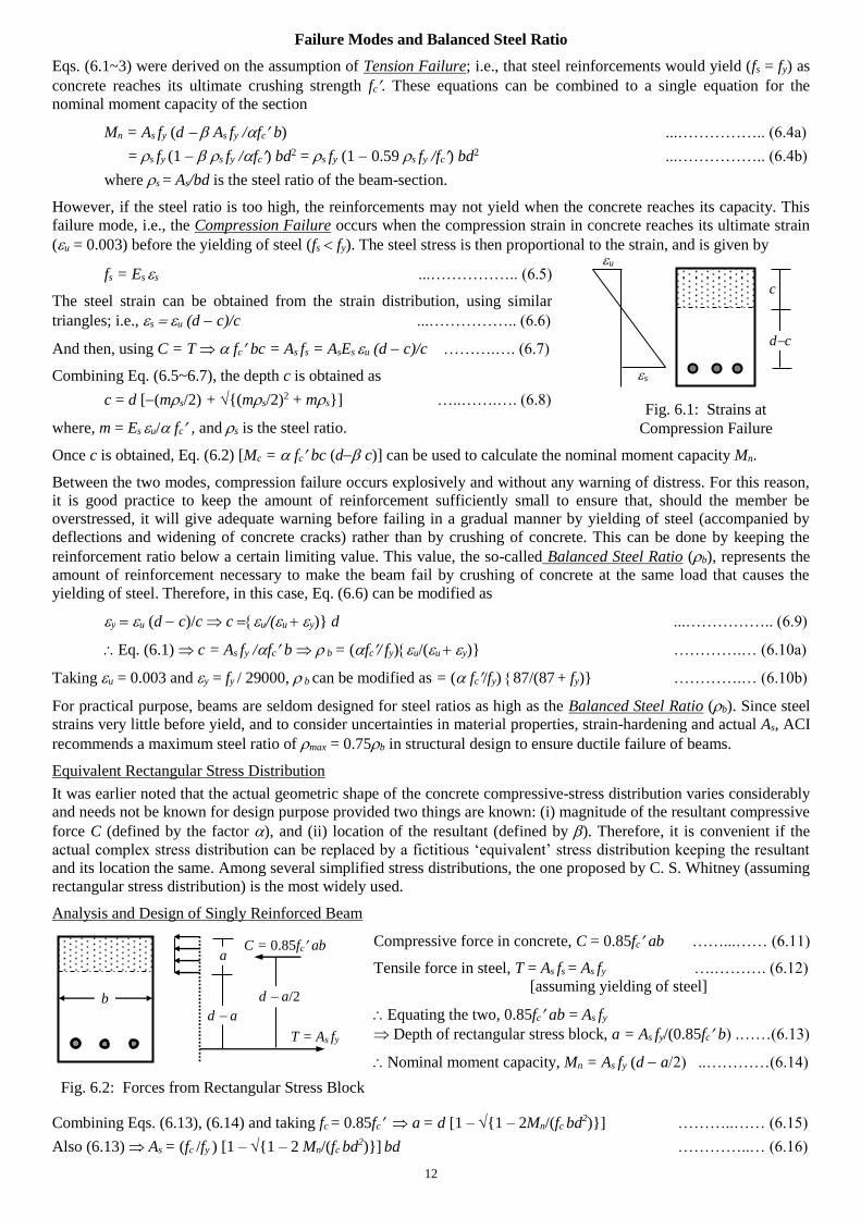
Failure Modes and Balanced Steel Ratio
Eqs. (6.1~3) were derived on the assumption of Tension Failure; i.e., that steel reinforcements would yield (fs = fy) as
concrete reaches its ultimate crushing strength fc. These equations can be combined to a single equation for the
nominal moment capacity of the section
Mn = As fy (d As fy /fc b) ...…………….. (6.4a)
= s fy (1 s fy /fc) bd2 = s fy (1 0.59 s fy /fc) bd2 ...…………….. (6.4b)
where s = As/bd is the steel ratio of the beam-section.
However, if the steel ratio is too high, the reinforcements may not yield when the concrete reaches its capacity. This
failure mode, i.e., the Compression Failure occurs when the compression strain in concrete reaches its ultimate strain
(u = 0.003) before the yielding of steel (fs fy). The steel stress is then proportional to the strain, and is given by
Once c is obtained, Eq. (6.2) [Mc = fc bc (d c)] can be used to calculate the nominal moment capacity Mn.
Between the two modes, compression failure occurs explosively and without any warning of distress. For this reason,
it is good practice to keep the amount of reinforcement sufficiently small to ensure that, should the member be
overstressed, it will give adequate warning before failing in a gradual manner by yielding of steel (accompanied by
deflections and widening of concrete cracks) rather than by crushing of concrete. This can be done by keeping the
reinforcement ratio below a certain limiting value. This value, the so-called Balanced Steel Ratio (b), represents the
amount of reinforcement necessary to make the beam fail by crushing of concrete at the same load that causes the
yielding of steel. Therefore, in this case, Eq. (6.6) can be modified as
yu (d c)/c c u/(u y)} d ...…………….. (6.9)
Eq. (6.1) c = As fy /fc b b = (fc/ fy)u/(u y)} ………….… (6.10a)
Taking u = 0.003 and y = fy / 29000, b can be modified as = ( fc/fy) 87/(87 +fy)} ………….… (6.10b)
For practical purpose, beams are seldom designed for steel ratios as high as the Balanced Steel Ratio (b). Since steel
strains very little before yield, and to consider uncertainties in material properties, strain-hardening and actual As, ACI
recommends a maximum steel ratio of max = 0.75b in structural design to ensure ductile failure of beams.
Equivalent Rectangular Stress Distribution
It was earlier noted that the actual geometric shape of the concrete compressive-stress distribution varies considerably
and needs not be known for design purpose provided two things are known: (i) magnitude of the resultant compressive
force C (defined by the factor ), and (ii) location of the resultant (defined by ). Therefore, it is convenient if the
actual complex stress distribution can be replaced by a fictitious ‘equivalent’ stress distribution keeping the resultant
and its location the same. Among several simplified stress distributions, the one proposed by C. S. Whitney (assuming
rectangular stress distribution) is the most widely used.
Analysis and Design of Singly Reinforced Beam
Combining Eqs. (6.13), (6.14) and taking fc = 0.85fc a = d [1 – {1 – 2Mn/(fc bd2)}] ………..…… (6.15)
Also (6.13) As = (fc /fy ) [1 – {1 – 2 Mn/(fc bd2)}] bd …………..… (6.16)
fs = Es s ...…………….. (6.5)
The steel strain can be obtained from the strain distribution, using similar
triangles; i.e.,su (d c)/c ...…………….. (6.6)
And then, using C = T fc bc = As fs = AsEs u (d c)/c ……….…. (6.7)
Combining Eq. (6.5~6.7), the depth c is obtained as
c = d [(ms/2) + {(ms/2)2 + ms}] …..…….…. (6.8)
where, m = Es u/ fc , and s is the steel ratio.
c
dc
s
u
Fig. 6.1: Strains at
Compression Failure
Compressive force in concrete, C = 0.85fc ab ……...…… (6.11)
Tensile force in steel, T = As fs = As fy ….………. (6.12)
[assuming yielding of steel]
Equating the two, 0.85fc ab = As fy
Depth of rectangular stress block, a = As fy/(0.85fc b) .……(6.13)
Nominal moment capacity, Mn = As fy (d a/2) ..…………(6.14)
a
T = As fy
C = 0.85fc ab
Fig. 6.2: Forces from Rectangular Stress Block
d a/2
d a
b
13
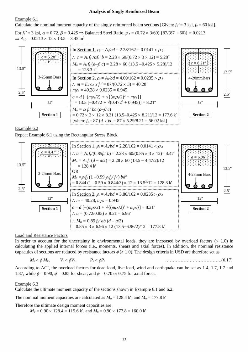
Analysis of Singly Reinforced Beam
Example 6.1
Calculate the nominal moment capacity of the singly reinforced beam sections [Given: fc = 3 ksi, fy = 60 ksi].
For fc = 3 ksi, = 0.72, = 0.425 Balanced Steel Ratio, b = (0.72 3/60) {87/(87 + 60)} = 0.0213
Asb = 0.0213 12 13.5 = 3.45 in2
12 12
Example 6.2
Repeat Example 6.1 using the Rectangular Stress Block.
12 12
Load and Resistance Factors
In order to account for the uncertainty in environmental loads, they are increased by overload factors ( 1.0) in
calculating the applied internal forces (i.e., moments, shears and axial forces). In addition, the nominal resistance
capacities of sections are reduced by resistance factors ( 1.0). The design criteria in USD are therefore set as
Mu Mn, Vu Vn, Pu Pn ……………………………….(6.17)
According to ACI, the overload factors for dead load, live load, wind and earthquake can be set as 1.4, 1.7, 1.7 and
1.87, while = 0.90, = 0.85 for shear, and = 0.70 or 0.75 for axial forces.
Example 6.3
Calculate the ultimate moment capacity of the sections shown in Example 6.1 and 6.2.
The nominal moment capacities are calculated as Mn = 128.4 k, and Mn = 177.8 k
Therefore the ultimate design moment capacities are
Mu = 0.90 128.4 = 115.6 k, and Mn = 0.90 177.8 = 160.0 k
3-25mm Bars
2.5
13.5
2.5
13.5
4-28mmBars
In Section 1, s = As/bd = 2.28/162 = 0.0141 b
c = As fy /fc b = 2.28 60/(0.72 3 12) = 5.28
Mn = As fy (d c) = 2.28 60 (13.5 0.425 5.28)/12
= 128.3 k
In Section 2, s = As/bd = 4.00/162 = 0.0235 b
m = Es u/ fc = 87/(0.72 3) = 40.28
ms = 40.28 0.0235 = 0.945
c = d [(ms/2) + {(ms/2)2 + ms}]
= 13.5 [0.472 + (0.4722 + 0.945)] = 8.21
Mn = fc bc (d c)
= 0.72 3 12 8.21 (13.50.425 8.21)/12 = 177.6 k
[where fs = 87 (dc)/c = 87 5.29/8.21 = 56.02 ksi]
Section 1 Section 2
3-25mm Bars
2.5
13.5
2.5
13.5
4-28mm Bars
In Section 1, s = As/bd = 2.28/162 = 0.0141 b
a = As fy/(0.85fc b) = 2.28 60/(0.85 3 12)= 4.47
Mn = As fy (d a/2) = 2.28 60 (13.5 4.47/2)/12
= 128.4 k
OR
Mn =sfy (1 0.59 sfy/ fc) bd2
= 0.844 (1 0.59 0.844/3) 12 13.52/12 = 128.3 k
In Section 2, s = As/bd = 3.80/162 = 0.0235 b
m = 40.28, ms = 0.945
c = d [(ms/2) + {(ms/2)2 + ms}] = 8.21
a = (0.72/0.85) 8.21 = 6.96
Mn = 0.85 fc ab (d a/2)
= 0.85 3 6.96 12 (13.56.96/2)/12 = 177.8 k
Section 1 Section 2
c = 8.21
c = 5.28
a = 4.47
a = 6.96
14
USD of Singly Reinforced Beam
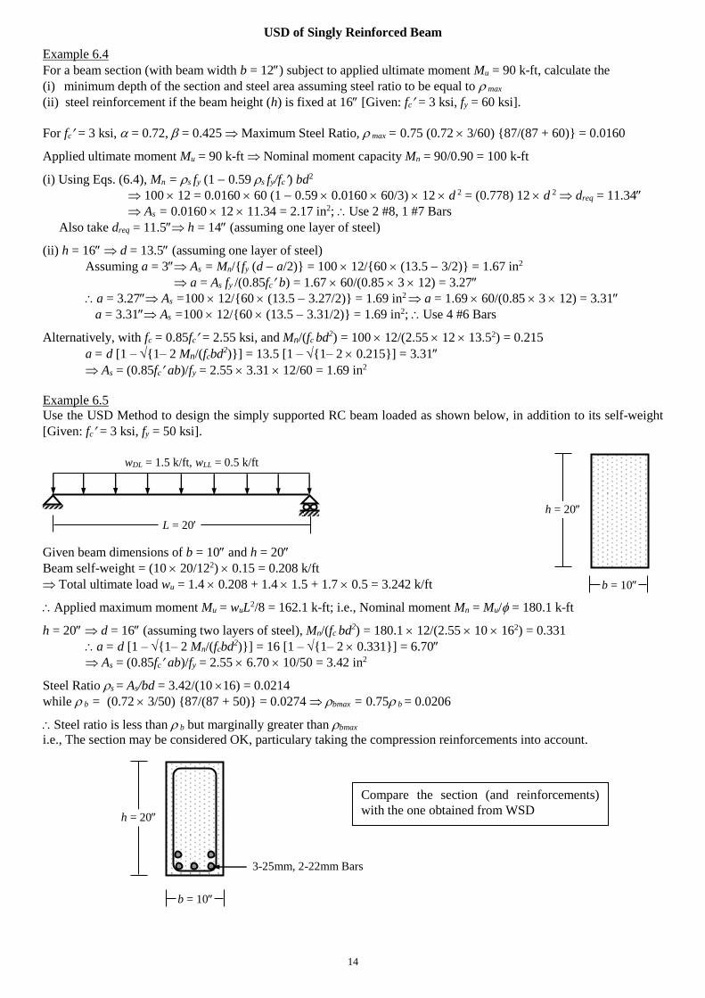
Example 6.4
For a beam section (with beam width b = 12) subject to applied ultimate moment Mu = 90 k-ft, calculate the
(i) minimum depth of the section and steel area assuming steel ratio to be equal to max
(ii) steel reinforcement if the beam height (h) is fixed at 16 [Given: fc = 3 ksi, fy = 60 ksi].
For fc = 3 ksi, = 0.72, = 0.425 Maximum Steel Ratio, max = 0.75 (0.72 3/60) {87/(87 + 60)} = 0.0160
Applied ultimate moment Mu = 90 k-ft Nominal moment capacity Mn = 90/0.90 = 100 k-ft
(i) Using Eqs. (6.4), Mn = s fy (1 0.59 s fy/fc) bd2
100 12 = 0.0160 60 (1 0.59 0.0160 60/3) 12 d 2 = (0.778) 12 d 2 dreq = 11.34
As = 0.0160 12 11.34 = 2.17 in2; Use 2 #8, 1 #7 Bars
Also take dreq = 11.5 h = 14 (assuming one layer of steel)
(ii) h = 16 d = 13.5 (assuming one layer of steel)
Assuming a = 3 As = Mn/{fy (d a/2)} = 100 12/{60 (13.5 3/2)} = 1.67 in2
a = As fy /(0.85fc b) = 1.67 60/(0.85 3 12) = 3.27
a = 3.27 As =100 12/{60 (13.5 3.27/2)} = 1.69 in2 a = 1.69 60/(0.85 3 12) = 3.31
a = 3.31 As =100 12/{60 (13.5 3.31/2)} = 1.69 in2; Use 4 #6 Bars
Alternatively, with fc = 0.85fc = 2.55 ksi, and Mn/(fc bd2) = 100 12/(2.55 12 13.52) = 0.215
a = d [1 – {1– 2 Mn/(fcbd2)}] = 13.5 [1 – {1– 2 0.215}] = 3.31
As = (0.85fc ab)/fy = 2.55 3.31 12/60 = 1.69 in2
Example 6.5
Use the USD Method to design the simply supported RC beam loaded as shown below, in addition to its self-weight
[Given: fc = 3 ksi, fy = 50 ksi].
Given beam dimensions of b = 10 and h = 20
Beam self-weight = (10 20/122) 0.15 = 0.208 k/ft
Total ultimate load wu = 1.4 0.208 + 1.4 1.5 + 1.7 0.5 = 3.242 k/ft
Applied maximum moment Mu = wuL2/8 = 162.1 k-ft; i.e., Nominal moment Mn = Mu/ = 180.1 k-ft
h = 20 d = 16 (assuming two layers of steel), Mn/(fc bd2) = 180.1 12/(2.55 10 162) = 0.331
a = d [1 – {1– 2 Mn/(fcbd2)}] = 16 [1 – {1– 2 0.331}] = 6.70
As = (0.85fc ab)/fy = 2.55 6.70 10/50 = 3.42 in2
Steel Ratio s = As/bd = 3.42/(10 16) = 0.0214
while b = (0.72 3/50) {87/(87 + 50)} = 0.0274 bmax = 0.75 b = 0.0206
Steel ratio is less than b but marginally greater than bmax
i.e., The section may be considered OK, particulary taking the compression reinforcements into account.
L = 20
wDL = 1.5 k/ft, wLL = 0.5 k/ft
h = 20
b = 10
h = 20
b = 10
3-25mm, 2-22mm Bars
Compare the section (and reinforcements)
with the one obtained from WSD
15
Analysis of Doubly Reinforced Beam
Because of the high design stresses, Doubly Reinforced beams are not as common as they are in WSD. But they are
useful for control of crack and deflection as well as binding the top and bottom reinforcements.
Moment Resisting Mechanism for Doubly Reinforced Beam
As shown in the formulation for WSD, in doubly reinforced beam, the nominal moment is resisted by two
mechanisms; i.e., reinforcement As1 acting with the concrete in compression, and reinforcement As2 (= As As1) acting
with the compression reinforcement As. From equilibrium, these two forces are given by
As1 fy = 0.85fc ab a = As1 fy (0.85fc b) …..………….(6.18)
and As2 fy = As fs As2 = As fs fy …..………….(6.19)
The value of fs can be calculated from the strain compatibility equation s u = (c d)/c
fs =Esu (c d )/c fy ….………….(6.20)
From which the ultimate moment capacity is calculated to be Mu = As1 fy (d a/2) + As2 fy (d d) ..………….(6.21)
If both the tensile and compression reinforcements yield, Mu = (As As) fy (d a/2) + As fy (d d) …...….….(6.22)
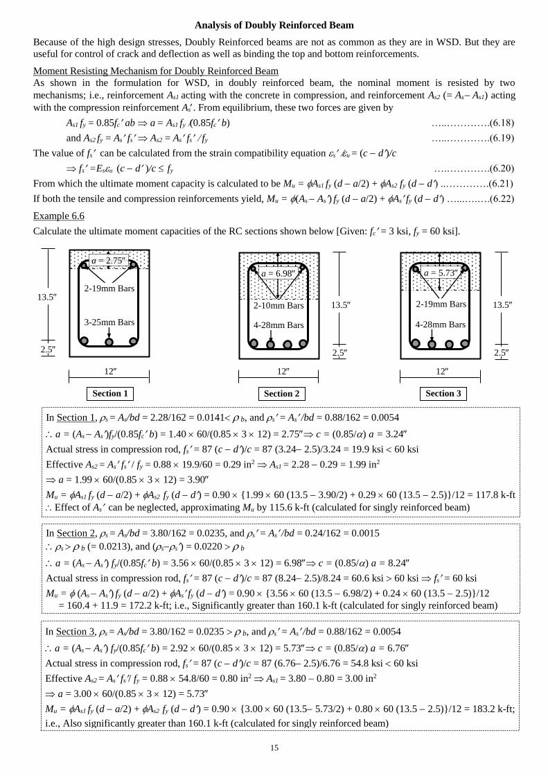
Example 6.6
Calculate the ultimate moment capacities of the RC sections shown below [Given: fc = 3 ksi, fy = 60 ksi].
12 12 12
2.5
13.5
In Section 3, s = As/bd = 3.80/162 = 0.0235 b, and s = As /bd = 0.88/162 = 0.0054
a = (As As) fy/(0.85fc b) = 2.92 60/(0.85 3 12) = 5.73 c = (0.85/) a = 6.76
Actual stress in compression rod, fs = 87 (c d)/c = 87 (6.76 2.5)/6.76 = 54.8 ksi 60 ksi
Effective As2 = As fs/ fy = 0.88 54.8/60 = 0.80 in2 As1 = 3.80 0.80 = 3.00 in2
a = 3.00 60/(0.85 3 12) = 5.73
Mu = As1 fy (d a/2) + As2 fy (d d) = 0.90 {3.00 60 (13.5 5.73/2) + 0.80 60 (13.5 2.5)}/12 = 183.2 k-ft;
i.e., Also significantly greater than 160.1 k-ft (calculated for singly reinforced beam)
Section 1
a = 2.75
2.5
13.5
4-28mm Bars
Section 3
a = 5.73
Section 2
a = 6.98
3-25mm Bars
2-19mm Bars
In Section 1, s = As/bd = 2.28/162 = 0.0141 b, and s = As /bd = 0.88/162 = 0.0054
a = (As As)fy/(0.85fc b) = 1.40 60/(0.85 3 12) = 2.75 c = (0.85/) a = 3.24
Actual stress in compression rod, fs = 87 (c d)/c = 87 (3.24 2.5)/3.24 = 19.9 ksi 60 ksi
Effective As2 = As fs / fy = 0.88 19.9/60 = 0.29 in2 As1 = 2.28 0.29 = 1.99 in2
a = 1.99 60/(0.85 3 12) = 3.90
Mu = As1 fy (d a/2) + As2 fy (d d) = 0.90 {1.99 60 (13.5 3.90/2) + 0.29 60 (13.5 2.5)}/12 = 117.8 k-ft
Effect of As can be neglected, approximating Mu by 115.6 k-ft (calculated for singly reinforced beam)
2.5
13.5
4-28mm Bars
2-10mm Bars 2-19mm Bars
In Section 2, s = As/bd = 3.80/162 = 0.0235, and s = As /bd = 0.24/162 = 0.0015
s b (= 0.0213), and (ss) = 0.0220 b
a = (As As) fy/(0.85fc b) = 3.56 60/(0.85 3 12) = 6.98 c = (0.85/) a = 8.24
Actual stress in compression rod, fs = 87 (c d)/c = 87 (8.24 2.5)/8.24 = 60.6 ksi 60 ksi fs = 60 ksi
Mu = (As As) fy (d a/2) + As fy (d d) = 0.90 {3.56 60 (13.5 6.98/2) + 0.24 60 (13.5 2.5)}/12
= 160.4 + 11.9 = 172.2 k-ft; i.e., Significantly greater than 160.1 k-ft (calculated for singly reinforced beam)
16
USD of Doubly Reinforced Beam
Example 6.7
Use the USD to design the cantilever beam AB loaded as shown in the figure below (in addition to its self-weight), if
working dead load wD = 1 k/ft, and working live load wL = 1 k/ft, assuming a steel ratio of max,
(i) as singly reinforced beam (b = 12), (ii) (12 14) cross-section [Given: fc = 4 ksi, fs = 60 ksi].
Using load factors 1.4 for dead load and 1.7 for live load, the ultimate load, wu = 1.4 1 + 1.7 1 = 3.1 k/ft
Ultimate moment, Mu = 3.1 102/2 = 155.0 k-ft Mn = 155.0/0.9 = 172.2 k-ft
For fc = 4 ksi, = 0.72 Balanced Steel Ratio, b = (0.72 4/60) {87/(87 + 60)} = 0.0284
Steel Ratio, s = 0.75 0.0284 = 0.0213
(i) Using Eqs. (6.4), Mn = s fy (1 0.59 s fy/fc) bd2
172.2 12 = 0.0213 60 (1 0.59 0.0213 60/4) 12 d2 = (1.037) 12 d 2
dreq = 12.89
d = 13.0 Cross-section (12 15.5) Self weight = 1.4 (12 15.5)/122 0.15 = 0.27 k/ft
Ultimate moment, Mu = (3.1 + 0.27) 102/2 = 168.6 k-ft Mn = 168.6/0.9 = 187.3 k-ft
187.3 12 = (1.037) 12 d 2 dreq = 13.44
As = 0.0213 12 13.44 = 3.44 in2; Use 2#8, 2#9 Bars at top
Also take dreq = 13.5 h = 16 (assuming one layer of steel)
(ii) Steel ratio will exceed max if designed as singly reinforced beam with b = 12, h = 14 d = 11.5
So the section should be designed as doubly reinforced beam.
Ultimate moment, Mu = (3.1 + 1.4 0.18) 102/2 = 167.3 k-ft Mn = 167.3/0.9 = 185.8 k-ft
M1 = s fy (1 0.59 s fy/fc) bd2 = (1.037) 12 11.5 2/12 = 137.2 k-ft M2 = Mn M1 = 185.8 137.2 = 48.6 k-ft
For M1, As1 = 0.0213 12 11.5 = 2.94 in2, and c = As1 fy/( fc b) = 2.94 60/(0.72 4 12) = 5.10
For moment M2, As2 = 48.6 12/{60 (11.5 2.5)} = 1.08 in2
As = As1 + As2 = 4.02 in2, Use 4 #9 Bars at top
Since c = 6.13, fs = 87 (c d )/c = 44.4 ksi fy
As = 48.6 12/{44.4 (11.5 2.5)} = 1.46 in2, Use 2 #8 Bars at bottom
Section B designed as (i) Singly Reinforced, (ii) Doubly Reinforced Section
B A
wD = 1 k/ft, wL = 1 k/ft
10
13.5
2.5
11.5
2.5
12
12
2#8, 2#9 4#9
2#8
17
Questions and Problems (3)
1. (i) What is the Ultimate Strength Design (USD) of Reinforced Concrete? Mention its differences from WSD.
(ii) What are the factors and in USD? Explain their variations with the ultimate strength of concrete.
(iii) What is Whitney’s stress block? Explain why it is used in USD.
(iv) What is the balanced steel ratio (b)? Why does the ACI recommend a maximum steel ratio less than b?
(v) What are the load and resistance factors? Explain why they are used in USD.
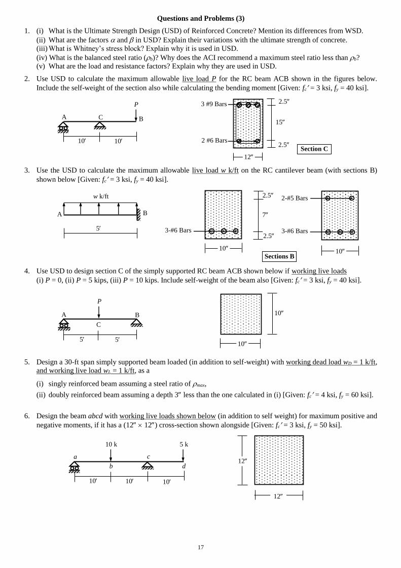
2. Use USD to calculate the maximum allowable live load P for the RC beam ACB shown in the figures below.
Include the self-weight of the section also while calculating the bending moment [Given: fc = 3 ksi, fy = 40 ksi].
3. Use the USD to calculate the maximum allowable live load w k/ft on the RC cantilever beam (with sections B)
shown below [Given: fc = 3 ksi, fy = 40 ksi].
4. Use USD to design section C of the simply supported RC beam ACB shown below if working live loads
(i) P = 0, (ii) P = 5 kips, (iii) P = 10 kips. Include self-weight of the beam also [Given: fc = 3 ksi, fy = 40 ksi].
5. Design a 30-ft span simply supported beam loaded (in addition to self-weight) with working dead load wD = 1 k/ft,
and working live load wL = 1 k/ft, as a
(i) singly reinforced beam assuming a steel ratio of max,
(ii) doubly reinforced beam assuming a depth 3 less than the one calculated in (i) [Given: fc = 4 ksi, fy = 60 ksi].
6. Design the beam abcd with working live loads shown below (in addition to self weight) for maximum positive and
negative moments, if it has a (12 12) cross-section shown alongside [Given: fc = 3 ksi, fy = 50 ksi].
5
A B
P
10
10
C
5
12
12
10
a
b
c
10
d
5 k
10
10 k
10
A B
P
12
15
Section C
C
10
2.5
2.5
3 #9 Bars
2 #6 Bars
5
A B
w k/ft
Sections B 10
7
2.5 3-#6 Bars
10
3-#6 Bars
2-#5 Bars 2.5
18
Following are some of the theoretical questions discussed so far, with guidelines for their answers.
The examination questions can be different or mixed or parts (based on the same topics/concepts).
Don’t memorize/copy this language, just follow the points and read books to prepare your own answers.
1. What is RC? Explain why steel and concrete are used in conjunction in RC.
In Reinforced Concrete (RC), steel is used to strengthen the section against tension in particular (also to resist
compression, shear, and control crack, deflection).
Concrete protects steel against weather, corrosion, fire, etc.
Steel and concrete have very good bond and similar coefficients of thermal expansion.
2. Explain the dependence of stress-strain behavior of concrete and steel on their ultimate strength.
Draw the - graphs of concrete and steel showing variations with ultimate strengths.
Increase in fc makes concrete stiffer and less ductile.
Increase in fy makes steel less ductile, reduces (even vanishes) the yield region but doesn’t affect the modulus
of elasticity.
3. What is a ‘transformed’ RC section? Explain with reference to cracked and uncracked section.
In a transformed RC section, reinforcements are ‘transformed’ to ‘equivalent’ concrete areas so that the entire
section behaves like a plain concrete section rather than a composite.
Draw the transformed cracked and uncracked sections and explain the term ‘n’.
4. Explain the difference between analysis and design of an RC section.
Analysis of an RC section is the calculation of its force/moment/load carrying capacity based on sectional
dimensions, steel areas and material properties. It is often referred to as review of a section and is particularly
useful in assessing the capacity of an existing structure.
Design of an RC section is the calculation of its sectional dimensions and steel areas based on material and
structural properties as well as applied loads. It is particularly useful in choosing a new structure/section to
withstand given loads.
5. What is a doubly reinforced RC section? Explain how it differs from a singly reinforced section.
If the concrete in the compression zone of an RC section is not sufficient to withstand the compressive forces,
additional compressive reinforcements may be provided to assist it. Thus, in a doubly reinforced RC section,
steel is provided in the tension as well as compression zones of concrete.
Stresses in the tension and compression reinforcements of a doubly reinforced beam are different. In USD, the
compression reinforcement may or may not yield.
Doubly reinforced sections are more common because in addition to resisting compression, the compressive
steel is required to control crack and deflection as well as to bind stirrups.
6. Why does the ACI recommend that in WSD, the value of compressive stress in steel (fs) be taken as twice the
value calculated from elastic analysis?
Derive the expression for fs using stress and strain distributions over the section.
Material nonlinearity in concrete lowers the stress in it, inducing more stress in the compression reinforcement
[Draw the - graphs of concrete and steel to explain].
Creep (long-term deflection) causes large strains in concrete, resulting in larger stresses in the compression
steel due to the resistance it provides to such strains.
7. Show the variations of stress and strain over an RC section as it is stressed gradually from uncracked to cracked
and ultimate failure condition.
Draw the appropriate diagrams for variation of strain and stress for uncracked, cracked (WSD) and ultimate
failure (USD) conditions.
For small moments (and stresses), the tensile stresses are within the tensile strength of concrete and the
section remains uncracked.
For larger moments (and stresses), the tensile stresses exceed the tensile strength of concrete but the
compressive stresses in concrete and tensile/compressive stresses in steel remain within elastic limits.
For even larger moments (and stresses), the tensile stress in steel reaches its yield point and compressive stress
in concrete exceeds the proportional limit so that the - relationships are no longer linear.
8. What is the USD method of RC design? Mention its differences from the WSD method.
In Ultimate Strength Design (USD) method, RC sections are designed to survive the maximum expected loads
within their lifetime without exceeding material strengths (i.e., suffering failure), but exceeding elastic limits.
In Working Stress Design (WSD) method, RC sections are designed to withstand the maximum working loads
without exceeding some predefined ‘safe’ stress levels (incorporating some ‘safety factors’). Usually these
stresses are within the elastic limits of the materials.
The USD is a more rational and usually more economical method than the WSD.
19
9. What are the factors and used in USD? Explain their variations with the ultimate strength of concrete.
The and factors are used in the USD method account for the material nonlinearity in calculating the
compressive forces in concrete and the moments induced
Show with figures for concrete stress distribution over compression zone.
Draw the variations of and with fc.
Draw the - diagrams of concrete of various strengths. Concretes of higher strength tend to be stiffer and less
ductile.
Since is the ratio of the average stress to maximum, this tends to decrease with fc.
Since is a factor indicating the distance of the resultant force from ultimate strain, this also tends to decrease
with fc.
10. What is Whitney’s stress block? Explain why it is used in USD.
The nonlinear - relationship for concrete is difficult to model, requiring different factors (like and
introduced in USD) to compute the compressive forces and moments induced.
As an alternative, Whitney proposed a simple stress block whose formulation and application is much easier.
Derive the appropriate parameters for Whitney’s stress block (e.g., ‘a’ and 0.85).
11. What are the maximum and minimum allowable steel ratios used in RC? Explain why they are used.
Write the formulae for pb, pmax, pmin and explain the terms in them.
If the steel ratio exceeds pb, the failure of the RC section will be initiated by the crushing of concrete rather
than the yielding of steel. This is highly undesirable due to the sudden and explosive nature of concrete
crushing compared to the more ductile mode of steel yielding [Explain them using - diagrams of steel and
concrete].
If the steel ratio is set below pmin, the tension steel will not be sufficient to resist the tensile forces induced and
the structural performance of the RC section will not be better than the behavior of a pure concrete section.
Therefore, failure of the section will follow immediately after the tension cracking of the section.
12. What are the load and resistance factors? Explain why they are used in USD.
Load factors are provided to account for the uncertainty in assumed working loads, increasing them to the
maximum possible loads (statistically expected) during the lifetime of the structure. In the USD, RC sections
are designed to survive these maximum loads without suffering structural failure [Give examples for DL, LL,
Wind, EQ etc].
Resistance factors are provided to consider the uncertainty in the material strengths and structural dimensions,
reducing them to the statistically expected minimum levels depending on the construction of the materials and
importance of the structures [Give examples for moment, shear and axial forces for both steel and concrete].
20
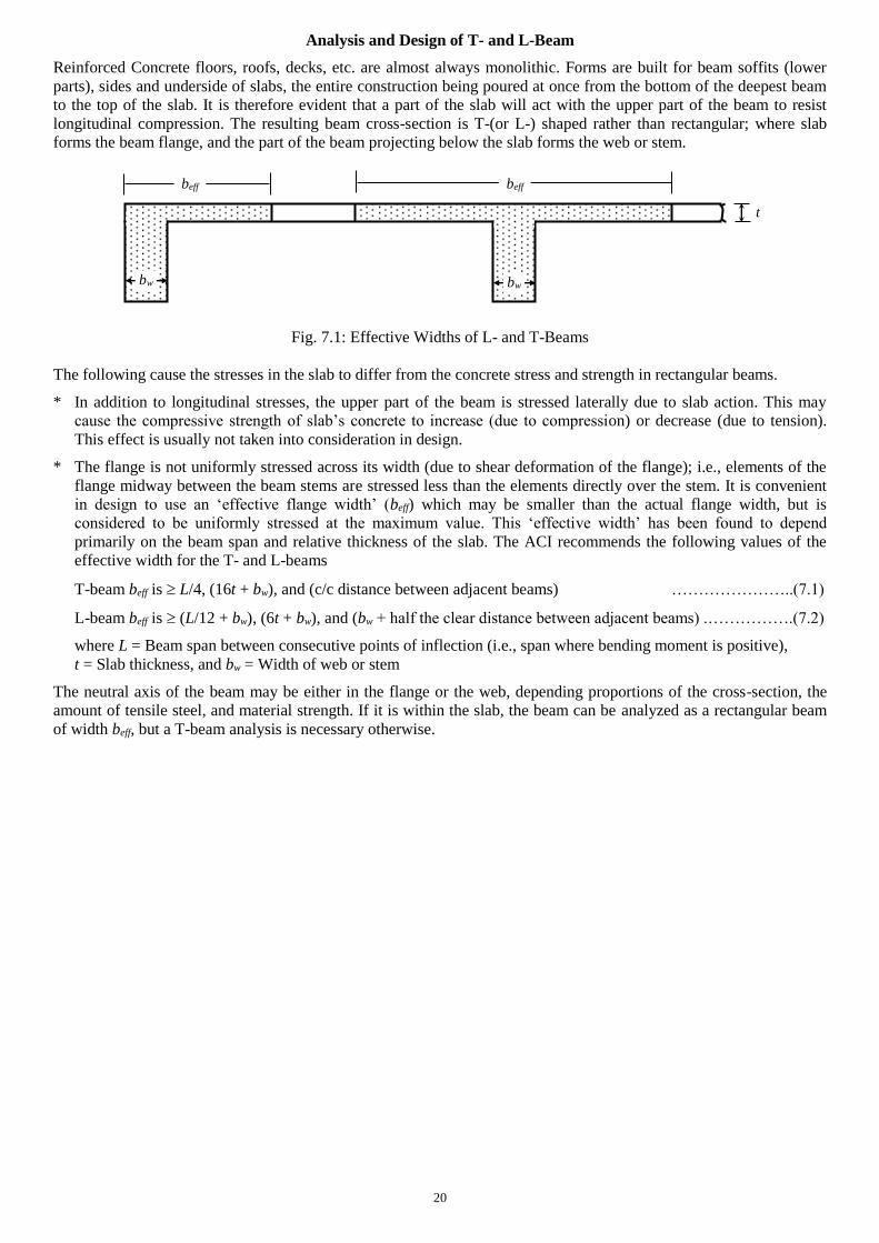
Analysis and Design of T- and L-Beam
Reinforced Concrete floors, roofs, decks, etc. are almost always monolithic. Forms are built for beam soffits (lower
parts), sides and underside of slabs, the entire construction being poured at once from the bottom of the deepest beam
to the top of the slab. It is therefore evident that a part of the slab will act with the upper part of the beam to resist
longitudinal compression. The resulting beam cross-section is T-(or L-) shaped rather than rectangular; where slab
forms the beam flange, and the part of the beam projecting below the slab forms the web or stem.
Fig. 7.1: Effective Widths of L- and T-Beams
The following cause the stresses in the slab to differ from the concrete stress and strength in rectangular beams.
* In addition to longitudinal stresses, the upper part of the beam is stressed laterally due to slab action. This may
cause the compressive strength of slab’s concrete to increase (due to compression) or decrease (due to tension).
This effect is usually not taken into consideration in design.
* The flange is not uniformly stressed across its width (due to shear deformation of the flange); i.e., elements of the
flange midway between the beam stems are stressed less than the elements directly over the stem. It is convenient
in design to use an ‘effective flange width’ (beff) which may be smaller than the actual flange width, but is
considered to be uniformly stressed at the maximum value. This ‘effective width’ has been found to depend
primarily on the beam span and relative thickness of the slab. The ACI recommends the following values of the
effective width for the T- and L-beams
T-beam beff is L/4, (16t + bw), and (c/c distance between adjacent beams) …………………..(7.1)
L-beam beff is (L/12 + bw), (6t + bw), and (bw + half the clear distance between adjacent beams) .…………….(7.2)
where L = Beam span between consecutive points of inflection (i.e., span where bending moment is positive),
t = Slab thickness, and bw = Width of web or stem
The neutral axis of the beam may be either in the flange or the web, depending proportions of the cross-section, the
amount of tensile steel, and material strength. If it is within the slab, the beam can be analyzed as a rectangular beam
of width beff, but a T-beam analysis is necessary otherwise.
beff beff
bw bw
t
21
Working Stress Design of T- (and L-) Beam
Fig. 7.2: Working Strain and Stress distribution in T-Beam
The equation of k [= n/(n+ r)] for rectangular beam can be used in T-beam also, provided the value of n (= Es/Ec) and r
(= fs/fc) are known. However, the actual r is usually not known for T-beams, although the maximum allowable stresses
are, since the compressive area provided by the slab is so large that the actual fc is some fraction of its allowable value.
In Fig. 7.2, neglecting the small (darkened) compressive area in the web, the total compressive force in concrete is
C {(fc + fc (kd t)/(kd))/2}(bt) = fc {1 t/(2kd)}(beff t) …………….…(7.3)
which is equal to the tensile force T (= As fs) in steel. …………….…(7.4)
Obtaining (fs/fc) from the combination of Eqs. (7.3) and (7.4), the following expression for k is obtained,
k = {ns + (t/d)2/2}/{ns + (t/d)} …………….…(7.5)
The distance to the resultant of compression from the upper face of the beam is
z = (3kd 2t)/(2kd t) (t/3) ………...….…(7.6)
and the moment arm of the couple (formed by C and T) is, jd = d z ………...….…(7.7)
The resisting moments of steel and concrete are given by
Ms = T jd = As fs jd ………...….… (7.8)
Mc = C jd = fc {1 t/(2kd)}(beff t) jd …..…...………(7.9)
Since the Eq. (7.5) for k requires the steel ratio s (= As/beff d), simplified approximate equation for As can be derived
for design problems based on assumed z t/2, which is always a conservative estimate; i.e.,
As Ms/{fs(d t/2)} ………...….…(7.10)
Example 7.1
Use the WSD Method to design the simply supported T-beam loaded as shown below, in addition to its self-weight if
it is part of a beam system carrying a 4 thick slab (with FF = 30 psf, RW = 80 psf and LL = 40 psf) a transverse
distance 10 c/c apart [Given: fc = 3 ksi, fcall = 1.35 ksi, fsall = 20 ksi].
For fc = 3 ksi = 3000 psi, n = 9, fcall = 1.35 ksi, fsall = 20 ksi r = 14.81
Given beam dimensions of b = 10 and h = 20
Weight from slab = 4/12 150 + 30 + 80 + 40 = 200 psf = 0.20 ksf
For beam c/c distance = 10, the superimposed load per ft is w0 = 0.20 10 = 2.0 k/ft
Beam self-weight = (10 20/122) 0.15 = 0.208 k/ft Total load w = 2 + 0.208 = 2.208 k/ft
Mmax = wL2/8 = 2.208 202/8 = 110.4 k-ft
Also beff = Minimum of [L/4 (= 60), 16t + bw (= 64 + 10 = 74), and c/c distance (= 120)] = 60
Assuming two layers of bottom steel, d = 20 + 4 4 = 20, As 110.4 12/{20 (20 4/2)} = 3.68 in2
ns = 9 3.68/(60 20) = 0.0276 k = 0.209, kd = 0.209 20 = 4.18 t
z = (3 4.18 2 4)/(2 4.18 4) (4/3) = 1.39 jd = d z = 18.61
As = 110.4 12/(20 18.61) = 3.56 in2; i.e., Use 6 #7 Bars in two layers
and concrete stress fc = As fs /[{1 t/(2kd)}( beff t)] = 3.56 20/(1 4/8.36)(60 4) = 0.57 ksi fcall (OK)
beff
bw
As
d
kd
c fc
fs s
fc (kdt)/(kd) t
Neutral Axis
L = 20
w0 = 2 k/ft
h = 20
b =10
t = 4
22
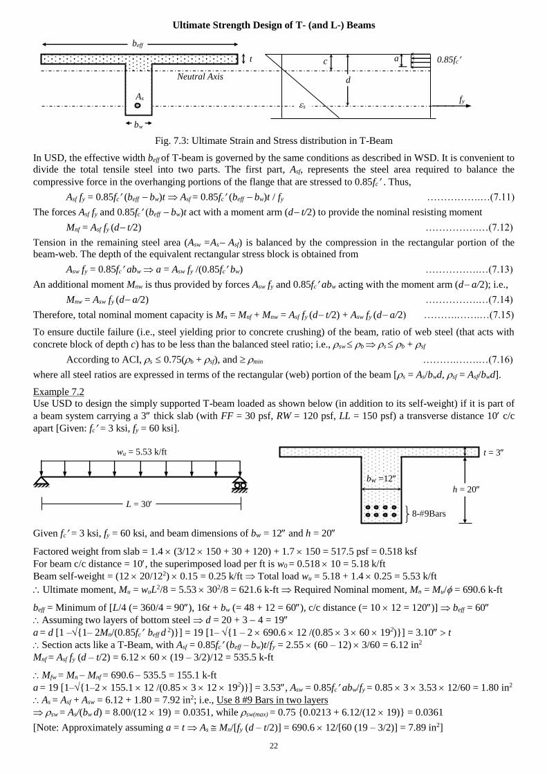
Ultimate Strength Design of T- (and L-) Beams
Fig. 7.3: Ultimate Strain and Stress distribution in T-Beam
In USD, the effective width beff of T-beam is governed by the same conditions as described in WSD. It is convenient to
divide the total tensile steel into two parts. The first part, Asf, represents the steel area required to balance the
compressive force in the overhanging portions of the flange that are stressed to 0.85fc . Thus,
Asf fy = 0.85fc (beff bw)t Asf = 0.85fc (beff bw)t / fy …………….…(7.11)
The forces Asf fy and 0.85fc (beff bw)t act with a moment arm (d t/2) to provide the nominal resisting moment
Mnf = Asf fy (d t/2) …………….…(7.12)
Tension in the remaining steel area (Asw =As Asf) is balanced by the compression in the rectangular portion of the
beam-web. The depth of the equivalent rectangular stress block is obtained from
Asw fy = 0.85fc abw a = Asw fy /(0.85fc bw) …………….…(7.13)
An additional moment Mnw is thus provided by forces Asw fy and 0.85fc abw acting with the moment arm (d a/2); i.e.,
Mnw = Asw fy (d a/2) …………….…(7.14)
Therefore, total nominal moment capacity is Mn = Mnf + Mnw = Asf fy (d t/2) + Asw fy (d a/2) ……….…….…(7.15)
To ensure ductile failure (i.e., steel yielding prior to concrete crushing) of the beam, ratio of web steel (that acts with
concrete block of depth c) has to be less than the balanced steel ratio; i.e., sw b s b + sf
According to ACI, s 0.75(b + sf), and min ……….…….…(7.16)
where all steel ratios are expressed in terms of the rectangular (web) portion of the beam [s = As/bwd, sf = Asf/bwd].
Example 7.2
Use USD to design the simply supported T-beam loaded as shown below (in addition to its self-weight) if it is part of
a beam system carrying a 3 thick slab (with FF = 30 psf, RW = 120 psf, LL = 150 psf) a transverse distance 10 c/c
apart [Given: fc = 3 ksi, fy = 60 ksi].
Given fc = 3 ksi, fy = 60 ksi, and beam dimensions of bw = 12 and h = 20
Factored weight from slab = 1.4 (3/12 150 + 30 + 120) + 1.7 150 = 517.5 psf = 0.518 ksf
For beam c/c distance = 10, the superimposed load per ft is w0 = 0.518 10 = 5.18 k/ft
Beam self-weight = (12 20/122) 0.15 = 0.25 k/ft Total load wu = 5.18 + 1.4 0.25 = 5.53 k/ft
Ultimate moment, Mu = wuL2/8 = 5.53 302/8 = 621.6 k-ft Required Nominal moment, Mn = Mu/ = 690.6 k-ft
beff = Minimum of [L/4 (= 360/4 = 90), 16t + bw (= 48 + 12 = 60), c/c distance (= 10 12 = 120)] beff = 60
Assuming two layers of bottom steel d = 20 + 3 4 = 19
a = d [1 –{1– 2Mn/(0.85fc beff d 2)}] = 19 [1– {1 – 2 690.6 12 /(0.85 3 60 192)}] = 3.10 t
Section acts like a T-Beam, with Asf = 0.85fc (beff – bw)t/fy = 2.55 (60 – 12) 3/60 = 6.12 in2
Mnf = Asf fy (d – t/2) = 6.12 60 (19 – 3/2)/12 = 535.5 k-ft
Mfw = Mn Mnf = 690.6 535.5 = 155.1 k-ft
a = 19 [1–{1–2 155.1 12 /(0.85 3 12 192)}] = 3.53, Asw = 0.85fc abw/fy = 0.85 3 3.53 12/60 = 1.80 in2
As = Asf + Asw = 6.12 + 1.80 = 7.92 in2; i.e., Use 8 #9 Bars in two layers
sw = As/(bw d) = 8.00/(12 19) = 0.0351, while sw(max) = 0.75 {0.0213 + 6.12/(12 19)} = 0.0361
[Note: Approximately assuming a = t As Mn/[fy (d – t/2)] = 690.6 12/[60 (19 – 3/2)] = 7.89 in2]
d
c
fy s
0.85fc
L = 30
wu = 5.53 k/ft
h = 20
t = 3
bw =12
bw
As
t
Neutral Axis
beff
a
8-9Bars
23
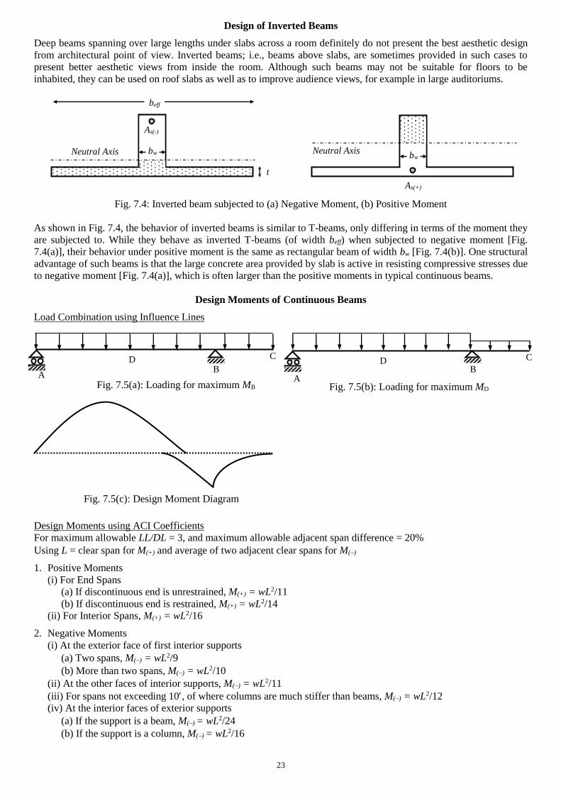
Design of Inverted Beams
Deep beams spanning over large lengths under slabs across a room definitely do not present the best aesthetic design
from architectural point of view. Inverted beams; i.e., beams above slabs, are sometimes provided in such cases to
present better aesthetic views from inside the room. Although such beams may not be suitable for floors to be
inhabited, they can be used on roof slabs as well as to improve audience views, for example in large auditoriums.
Fig. 7.4: Inverted beam subjected to (a) Negative Moment, (b) Positive Moment
As shown in Fig. 7.4, the behavior of inverted beams is similar to T-beams, only differing in terms of the moment they
are subjected to. While they behave as inverted T-beams (of width beff) when subjected to negative moment [Fig.
7.4(a)], their behavior under positive moment is the same as rectangular beam of width bw [Fig. 7.4(b)]. One structural
advantage of such beams is that the large concrete area provided by slab is active in resisting compressive stresses due
to negative moment [Fig. 7.4(a)], which is often larger than the positive moments in typical continuous beams.
Design Moments of Continuous Beams
Load Combination using Influence Lines
Design Moments using ACI Coefficients
For maximum allowable LL/DL = 3, and maximum allowable adjacent span difference = 20%
Using L = clear span for M(+) and average of two adjacent clear spans for M()
1. Positive Moments
(i) For End Spans
(a) If discontinuous end is unrestrained, M(+) = wL2/11
(b) If discontinuous end is restrained, M(+) = wL2/14
(ii) For Interior Spans, M(+) = wL2/16
2. Negative Moments
(i) At the exterior face of first interior supports
(a) Two spans, M() = wL2/9
(b) More than two spans, M() = wL2/10
(ii) At the other faces of interior supports, M() = wL2/11
(iii) For spans not exceeding 10, of where columns are much stiffer than beams, M() = wL2/12
(iv) At the interior faces of exterior supports
(a) If the support is a beam, M() = wL2/24
(b) If the support is a column, M() = wL2/16
bw
As(-)
t
Neutral Axis
beff
bw
As(+)
Neutral Axis
A B
C D
A B
C D
Fig. 7.5(a): Loading for maximum MB Fig. 7.5(b): Loading for maximum MD
Fig. 7.5(c): Design Moment Diagram
24
Questions and Problems (4)
1. (i) Mention the differences and advantages of designing beams as T-beams compared to rectangular beams.
(ii) Explain the differences between flexural stress distribution over T- and rectangular beams (and their effects).
(iii) Mention and explain the ACI-recommended effective widths of T- and L-Beams.
* Explain the differences between flexural stress distribution over T- and rectangular beams (and their effects).
Two-dimensional stress distribution due to tension/compression from slab (effect on fc).
Variation of stresses across the width of beam due to shear deformations (effect on beff).
* Mention and explain the ACI-recommended effective widths of T- and L-Beams.
Variation of stress across the width of the beams.
Mention the T-beam widths and L-beam widths.
2. Use the WSD method to design the end beam (L-section) at ‘a’ of the cantilever beam ab subjected to F0 = 10 k
acting (i) downward, (ii) upward on the beam (in addition to slab self weight plus FF = 20 psf, RW = 50 psf, LL =
30 psf and beam self weight) [Given: fc = 3 ksi, fs = 20 ksi].
3. Use the WSD method to design the section c of the fixed-ended beam ab shown in the figures below if
(i) P = 5 kips, (ii) P = 10 kips. Exclude the weights from the slab and beam [Given: fc = 3 ksi, fs = 18 ksi].
4. Answer the Question 2, using USD, assuming F0 to be live load [Given: fc = 3 ksi, fy = 50 ksi].
5. Answer the Question 3, using USD, assuming P to be live load [Given: fc = 3 ksi, fy = 40 ksi].
c 10
4
Beam and Slab (c/c) Section
14
8
10
a b
10
PL/8 PL/8
PL/8
F0
10 12
4
Beam and Slab Sections
4
a b 18
25
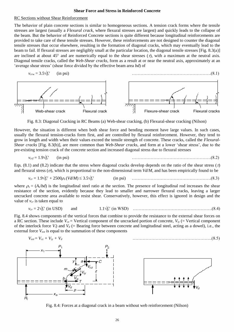
Shear Force and Stress in Plain Concrete
Other than axial force, bending moment and the resulting normal (i.e., axial and flexural) stresses, beams must also
have an adequate safety margin against other types of failure, some of which may be more dangerous than flexural
failure. Shear failure of RC, more properly called Diagonal Tension Failure (due to the mode of failure, i.e., as the
principal tensile stress that acts diagonally, as shown in Figs. 8.1 and 8.2) is one such example. In contrast with the
nature of flexural failure, it may occur suddenly (without any warning of distress). Therefore, RC beams are generally
provided with shear reinforcement to ensure flexural failure occurs before shear failure.
Example 8.1
Calculate the magnitude and direction of the maximum tensile stresses at points a, b, c, d of the simply supported RC
beam loaded as shown below.
Point V (k) (psi) M (k-ft) (psi) (psi)
a 0 0.00 50 900.0 900.0 0
b 5 28.13 37.5 337.5 339.8 4.7
c 10 75.00 0 0.0 75.0 45
d 5 28.13 37.5 337.5 2.3 85.3
5
w0 = 1 k/ft 5
10
a
5 10
c b
4@
5
d
d
c
a
b
5
5
5
−w0L/2 = −10
w0 L/2 = 10
SFD (k)
BMD (k-ft)
w0 L2/8 = 50
w0 L/4 = 5
3w0 L2/32 = 37.5
Fig. 8.1: Shear Failure of concrete beam: (a) Overall View,
(b) Detail near right support (Nilson)
= + (
tan 2= 2
a 900 900 b 339.8
0
339.8
900
c
75
75
d
2.3
2.3
(a)
(b)
Fig. 8.2: Stress Trajectories of Diagonal Tension
and Compression (Nilson)
Tension Trajectory
Compression Trajectory
26
Shear Force and Stress in Reinforced Concrete
RC Sections without Shear Reinforcement
The behavior of plain concrete sections is similar to homogeneous sections. A tension crack forms where the tensile
stresses are largest (usually a Flexural crack, where flexural stresses are largest) and quickly leads to the collapse of
the beam. But the behavior of Reinforced Concrete sections is quite different because longitudinal reinforcements are
provided to take care of these tensile stresses. However, these reinforcements are not designed to counter the diagonal
tensile stresses that occur elsewhere, resulting in the formation of diagonal cracks, which may eventually lead to the
beam to fail. If flexural stresses are negligibly small at the particular location, the diagonal tensile stresses [Fig. 8.3(a)]
are inclined at about 45 and are numerically equal to the shear stresses (), with a maximum at the neutral axis.
Diagonal tensile cracks, called the Web-Shear cracks, form as a result at or near the neutral axis, approximately at an
‘average shear stress’ (shear force divided by the effective beam area bd) of
vcrw = 3.5fc (in psi) ……………………………………………….(8.1)
However, the situation is different when both shear force and bending moment have large values. In such cases,
usually the flexural tension-cracks form first, and are controlled by flexural reinforcement. However, they tend to
grow in length and width when their values exceed the tensile strength of concrete. These cracks, called the Flexural-
Shear cracks [Fig. 8.3(b)], are more common than Web-Shear cracks, and form at a lower ‘shear stress’, due to the
pre-existing tension crack of the concrete section and increased diagonal stress due to flexural stresses
vcrf = 1.9fc (in psi) ……………………………………………….(8.2)
Eqs. (8.1) and (8.2) indicate that the stress where diagonal cracks develop depends on the ratio of the shear stress ()
and flexural stress (), which is proportional to the non-dimensional term Vd/M, and has been empirically found to be
vcr = 1.9fc + 2500s (Vd/M) 3.5fc (in psi) ……………………………………………….(8.3)
where s = (As/bd) is the longitudinal steel ratio at the section. The presence of longitudinal rod increases the shear
resistance of the section, evidently because they lead to smaller and narrower flexural cracks, leaving a larger
uncracked concrete area available to resist shear. Conservatively, however, this effect is ignored in design and the
value of vcr is taken equal to
vcr = 2fc (in USD) and 1.1fc (in WSD) ……………………………………………….(8.4)
Fig. 8.4 shows components of the vertical forces that combine to provide the resistance to the external shear forces on
a RC section. These include Vcz = Vertical component of the uncracked portion of concrete, Viy (= Vertical component
of the interlock force Vi) and Vd (= Bearing force between concrete and longitudinal steel, acting as a dowel), i.e., the
external force Vext is equal to the summation of these components
Vext = Vcz + Viy + Vd ……………………………………………….(8.5)
Fig. 8.3: Diagonal Cracking in RC Beams (a) Web-shear cracking, (b) Flexural-shear cracking (Nilson)
Fig. 8.4: Forces at a diagonal crack in a beam without web reinforcement (Nilson)
27
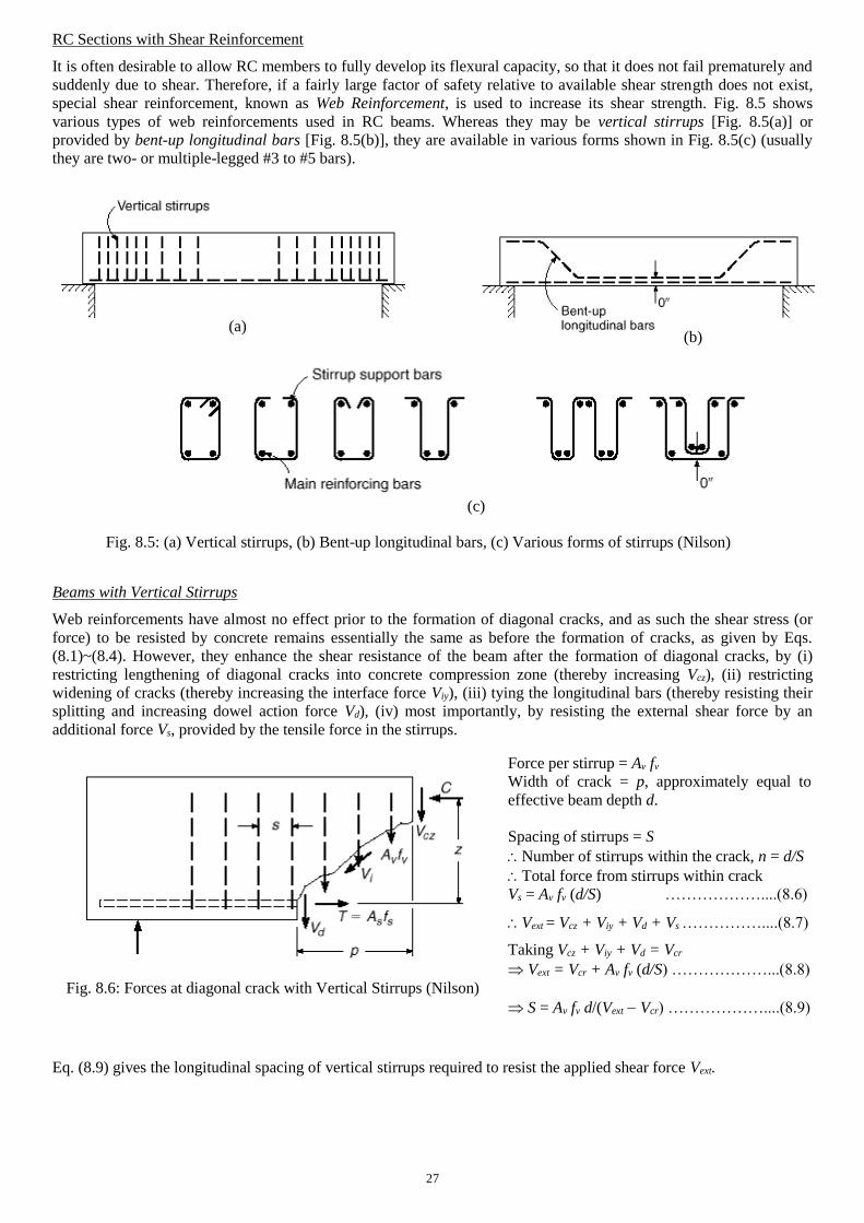
RC Sections with Shear Reinforcement
It is often desirable to allow RC members to fully develop its flexural capacity, so that it does not fail prematurely and
suddenly due to shear. Therefore, if a fairly large factor of safety relative to available shear strength does not exist,
special shear reinforcement, known as Web Reinforcement, is used to increase its shear strength. Fig. 8.5 shows
various types of web reinforcements used in RC beams. Whereas they may be vertical stirrups [Fig. 8.5(a)] or
provided by bent-up longitudinal bars [Fig. 8.5(b)], they are available in various forms shown in Fig. 8.5(c) (usually
they are two- or multiple-legged #3 to #5 bars).
Beams with Vertical Stirrups
Web reinforcements have almost no effect prior to the formation of diagonal cracks, and as such the shear stress (or
force) to be resisted by concrete remains essentially the same as before the formation of cracks, as given by Eqs.
(8.1)~(8.4). However, they enhance the shear resistance of the beam after the formation of diagonal cracks, by (i)
restricting lengthening of diagonal cracks into concrete compression zone (thereby increasing Vcz), (ii) restricting
widening of cracks (thereby increasing the interface force Viy), (iii) tying the longitudinal bars (thereby resisting their
splitting and increasing dowel action force Vd), (iv) most importantly, by resisting the external shear force by an
additional force Vs, provided by the tensile force in the stirrups.
Eq. (8.9) gives the longitudinal spacing of vertical stirrups required to resist the applied shear force Vext.
(a) (b)
(c)
Fig. 8.5: (a) Vertical stirrups, (b) Bent-up longitudinal bars, (c) Various forms of stirrups (Nilson)
Force per stirrup = Av fv
Width of crack = p, approximately equal to
effective beam depth d.
Spacing of stirrups = S
Number of stirrups within the crack, n = d/S
Total force from stirrups within crack
Vs = Av fv (d/S) ………………....(8.6)
Vext = Vcz + Viy + Vd + Vs ……………....(8.7)
Taking Vcz + Viy + Vd = Vcr
Vext = Vcr + Av fv (d/S) ………………...(8.8)
S = Av fv d/(Vext Vcr) ………………....(8.9)
Fig. 8.6: Forces at diagonal crack with Vertical Stirrups (Nilson)
28
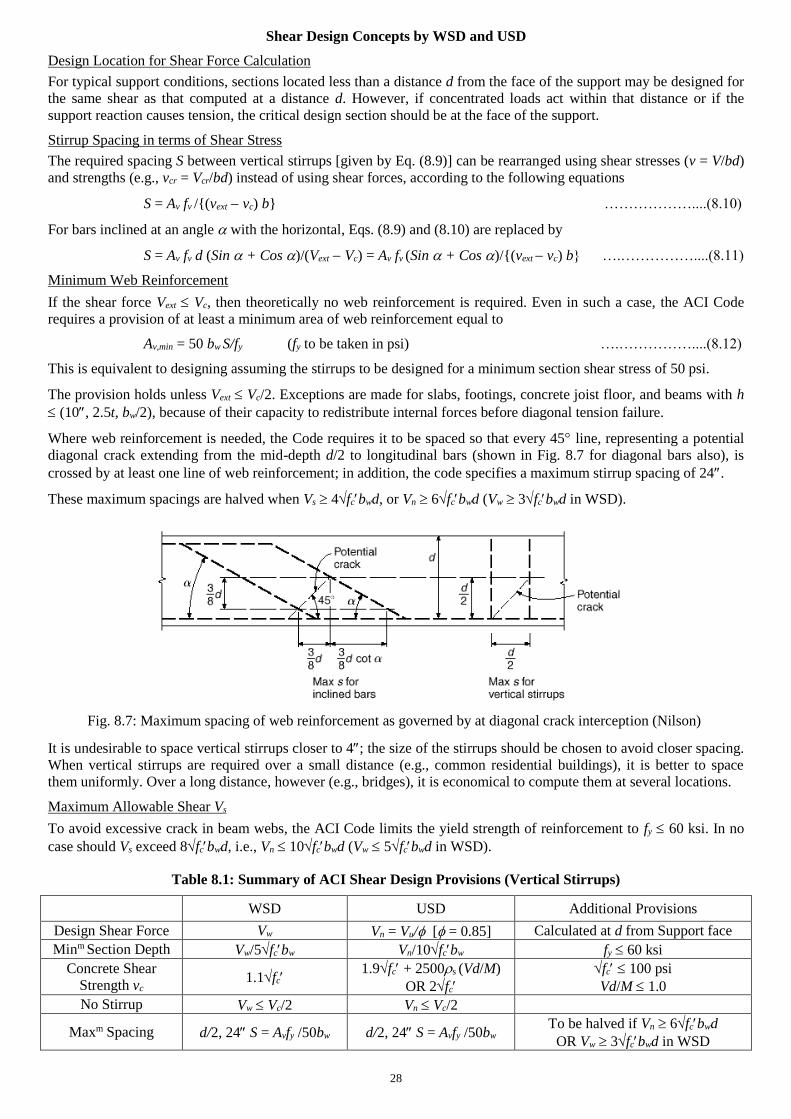
Shear Design Concepts by WSD and USD
Design Location for Shear Force Calculation
For typical support conditions, sections located less than a distance d from the face of the support may be designed for
the same shear as that computed at a distance d. However, if concentrated loads act within that distance or if the
support reaction causes tension, the critical design section should be at the face of the support.
Stirrup Spacing in terms of Shear Stress
The required spacing S between vertical stirrups [given by Eq. (8.9)] can be rearranged using shear stresses (v = V/bd)
and strengths (e.g., vcr = Vcr/bd) instead of using shear forces, according to the following equations
S = Av fv /{(vext vc) b} ………………....(8.10)
For bars inclined at an angle with the horizontal, Eqs. (8.9) and (8.10) are replaced by
S = Av fv d (Sin + Cos )/(Vext Vc) = Av fv (Sin + Cos )/{(vext vc) b} ….……………....(8.11)
Minimum Web Reinforcement
If the shear force Vext Vc, then theoretically no web reinforcement is required. Even in such a case, the ACI Code
requires a provision of at least a minimum area of web reinforcement equal to
Av,min = 50 bw S/fy (fy to be taken in psi) ….……………....(8.12)
This is equivalent to designing assuming the stirrups to be designed for a minimum section shear stress of 50 psi.
The provision holds unless Vext Vc/2. Exceptions are made for slabs, footings, concrete joist floor, and beams with h
(10, 2.5t, bw/2), because of their capacity to redistribute internal forces before diagonal tension failure.
Where web reinforcement is needed, the Code requires it to be spaced so that every 45 line, representing a potential
diagonal crack extending from the mid-depth d/2 to longitudinal bars (shown in Fig. 8.7 for diagonal bars also), is
crossed by at least one line of web reinforcement; in addition, the code specifies a maximum stirrup spacing of 24.
These maximum spacings are halved when Vs 4fcbwd, or Vn 6fcbwd (Vw 3fcbwd in WSD).
It is undesirable to space vertical stirrups closer to 4; the size of the stirrups should be chosen to avoid closer spacing.
When vertical stirrups are required over a small distance (e.g., common residential buildings), it is better to space
them uniformly. Over a long distance, however (e.g., bridges), it is economical to compute them at several locations.
Maximum Allowable Shear Vs
To avoid excessive crack in beam webs, the ACI Code limits the yield strength of reinforcement to fy 60 ksi. In no
case should Vs exceed 8fcbwd, i.e., Vn 10fcbwd (Vw 5fcbwd in WSD).
Table 8.1: Summary of ACI Shear Design Provisions (Vertical Stirrups)
WSD USD Additional Provisions
Design Shear Force Vw Vn = Vu/ [ = 0.85] Calculated at d from Support face
Minm Section Depth Vw/5fcbw Vn/10fcbw fy 60 ksi
Concrete Shear
Strength vc 1.1fc
1.9fc + 2500s (Vd/M)
OR 2fc
fc 100 psi
Vd/M 1.0
No Stirrup Vw Vc/2 Vn Vc/2
Maxm Spacing d/2, 24 S = Avfy /50bw d/2, 24 S = Avfy /50bw To be halved if Vn 6fcbwd
OR Vw 3fcbwd in WSD
Fig. 8.7: Maximum spacing of web reinforcement as governed by at diagonal crack interception (Nilson)
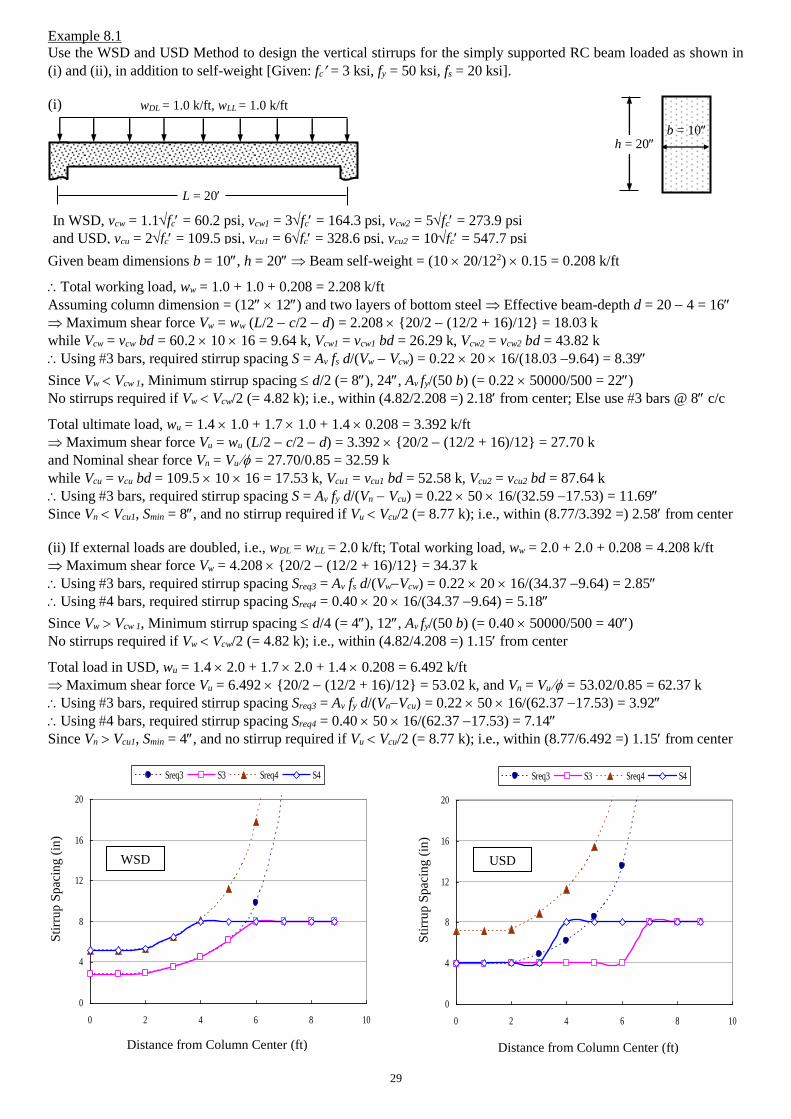
29
Example 8.1
Use the WSD and USD Method to design the vertical stirrups for the simply supported RC beam loaded as shown in
(i) and (ii), in addition to self-weight [Given: fc = 3 ksi, fy = 50 ksi, fs = 20 ksi].
(i)
Given beam dimensions b = 10, h = 20 Beam self-weight = (10 20/122) 0.15 = 0.208 k/ft
Total working load, ww = 1.0 + 1.0 + 0.208 = 2.208 k/ft
Assuming column dimension = (12 12) and two layers of bottom steel Effective beam-depth d = 20 4 = 16
Maximum shear force Vw = ww (L/2 c/2 d) = 2.208 {20/2 (12/2 + 16)/12} = 18.03 k
while Vcw = vcw bd = 60.2 10 16 = 9.64 k, Vcw1 = vcw1 bd = 26.29 k, Vcw2 = vcw2 bd = 43.82 k
Using 3 bars, required stirrup spacing S = Av fs d/(Vw Vcw) = 0.22 20 16/(18.03 9.64) = 8.39
Since Vw Vcw 1, Minimum stirrup spacing d/2 (= 8), 24, Av fy/(50 b) (= 0.22 50000/500 = 22)
No stirrups required if Vw Vcw/2 (= 4.82 k); i.e., within (4.82/2.208 =) 2.18 from center; Else use 3 bars @ 8 c/c
Total ultimate load, wu = 1.4 1.0 + 1.7 1.0 + 1.4 0.208 = 3.392 k/ft
Maximum shear force Vu = wu (L/2 c/2 d) = 3.392 {20/2 (12/2 + 16)/12} = 27.70 k
and Nominal shear force Vn = Vu = 27.70/0.85 = 32.59 k
while Vcu = vcu bd = 109.5 10 16 = 17.53 k, Vcu1 = vcu1 bd = 52.58 k, Vcu2 = vcu2 bd = 87.64 k
Using 3 bars, required stirrup spacing S = Av fy d/(Vn Vcu) = 0.22 50 16/(32.59 17.53) = 11.69
Since Vn Vcu1, Smin = 8, and no stirrup required if Vu Vcu/2 (= 8.77 k); i.e., within (8.77/3.392 =) 2.58 from center
(ii) If external loads are doubled, i.e., wDL = wLL = 2.0 k/ft; Total working load, ww = 2.0 + 2.0 + 0.208 = 4.208 k/ft
Maximum shear force Vw = 4.208 {20/2 (12/2 + 16)/12} = 34.37 k
Using 3 bars, required stirrup spacing Sreq3 = Av fs d/(VwVcw) = 0.22 20 16/(34.37 9.64) = 2.85
Using 4 bars, required stirrup spacing Sreq4 = 0.40 20 16/(34.37 9.64) = 5.18
Since Vw Vcw 1, Minimum stirrup spacing d/4 (= 4), 12, Av fy/(50 b) (= 0.40 50000/500 = 40)
No stirrups required if Vw Vcw/2 (= 4.82 k); i.e., within (4.82/4.208 =) 1.15 from center
Total load in USD, wu = 1.4 2.0 + 1.7 2.0 + 1.4 0.208 = 6.492 k/ft
Maximum shear force Vu = 6.492 {20/2 (12/2 + 16)/12} = 53.02 k, and Vn = Vu = 53.02/0.85 = 62.37 k
Using 3 bars, required stirrup spacing Sreq3 = Av fy d/(VnVcu) = 0.22 50 16/(62.37 17.53) = 3.92
Using 4 bars, required stirrup spacing Sreq4 = 0.40 50 16/(62.37 17.53) = 7.14
Since Vn Vcu1, Smin = 4, and no stirrup required if Vu Vcu/2 (= 8.77 k); i.e., within (8.77/6.492 =) 1.15 from center
L = 20
wDL = 1.0 k/ft, wLL = 1.0 k/ft
h = 20
In WSD, vcw = 1.1fc = 60.2 psi, vcw1 = 3fc = 164.3 psi, vcw2 = 5fc = 273.9 psi
and USD, vcu = 2fc = 109.5 psi, vcu1 = 6fc = 328.6 psi, vcu2 = 10fc = 547.7 psi
b = 10
0
4
8
12
16
20
0 2 4 6 8 10
Distance from Column Center (ft)
Stirr
up S
pacin
g (
in)
Sreq3 S3 Sreq4 S4
WSD
Distance from Column Center (ft)
Sti
rru
p S
paci
ng
(in
)
0
4
8
12
16
20
0 2 4 6 8 10
Distance from Column Center (ft)
Stirr
up S
pacin
g (
in)
Sreq3 S3 Sreq4 S4
USD
Distance from Column Center (ft)
Sti
rru
p S
pac
ing
(in
)
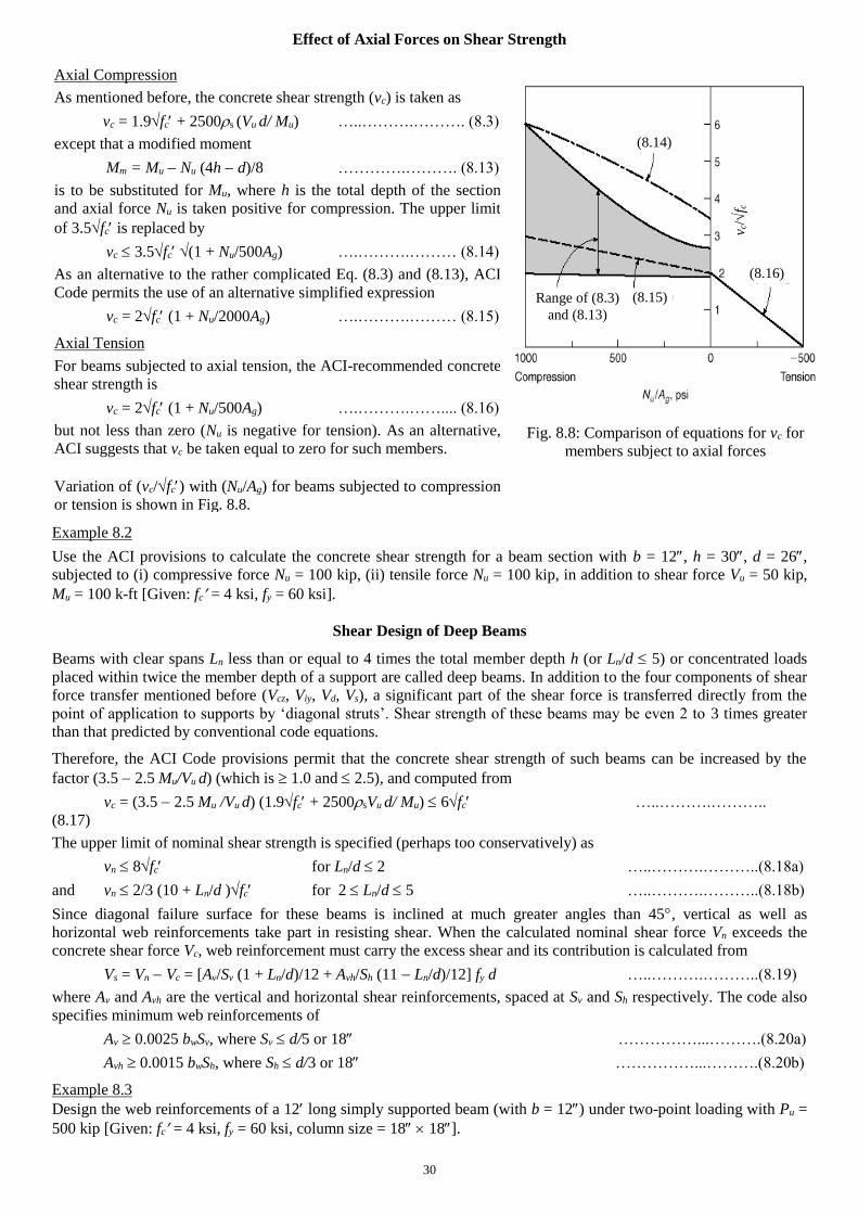
30
Effect of Axial Forces on Shear Strength
Example 8.2
Use the ACI provisions to calculate the concrete shear strength for a beam section with b = 12, h = 30, d = 26,
subjected to (i) compressive force Nu = 100 kip, (ii) tensile force Nu = 100 kip, in addition to shear force Vu = 50 kip,
Mu = 100 k-ft [Given: fc = 4 ksi, fy = 60 ksi].
Shear Design of Deep Beams
Beams with clear spans Ln less than or equal to 4 times the total member depth h (or Ln/d 5) or concentrated loads
placed within twice the member depth of a support are called deep beams. In addition to the four components of shear
force transfer mentioned before (Vcz, Viy, Vd, Vs), a significant part of the shear force is transferred directly from the
point of application to supports by ‘diagonal struts’. Shear strength of these beams may be even 2 to 3 times greater
than that predicted by conventional code equations.
Therefore, the ACI Code provisions permit that the concrete shear strength of such beams can be increased by the
factor (3.5 2.5 Mu/Vu d) (which is 1.0 and 2.5), and computed from
vc = (3.5 2.5 Mu /Vu d) (1.9fc + 2500sVu d/ Mu) 6fc …..……….………..
(8.17)
The upper limit of nominal shear strength is specified (perhaps too conservatively) as
vn 8fc for Ln/d 2 …..……….………..(8.18a)
and vn 2/3 (10 + Ln/d )fc for 2 Ln/d 5 …..……….………..(8.18b)
Since diagonal failure surface for these beams is inclined at much greater angles than 45, vertical as well as
horizontal web reinforcements take part in resisting shear. When the calculated nominal shear force Vn exceeds the
concrete shear force Vc, web reinforcement must carry the excess shear and its contribution is calculated from
Vs = Vn Vc = [Av/Sv (1 + Ln/d)/12 + Avh/Sh (11 Ln/d)/12] fy d …..……….………..(8.19)
where Av and Avh are the vertical and horizontal shear reinforcements, spaced at Sv and Sh respectively. The code also
specifies minimum web reinforcements of
Av 0.0025 bwSv, where Sv d/5 or 18 ……………...……….(8.20a)
Avh 0.0015 bwSh, where Sh d/3 or 18 ……………...……….(8.20b)
Example 8.3
Design the web reinforcements of a 12 long simply supported beam (with b = 12) under two-point loading with Pu =
500 kip [Given: fc = 4 ksi, fy = 60 ksi, column size = 18 18].
Axial Compression
As mentioned before, the concrete shear strength (vc) is taken as
vc = 1.9fc + 2500s (Vu d/ Mu) …..……….………. (8.3)
except that a modified moment
Mm = Mu Nu (4h d)/8 ………….………. (8.13)
is to be substituted for Mu, where h is the total depth of the section
and axial force Nu is taken positive for compression. The upper limit
of 3.5fc is replaced by
vc 3.5fc (1 + Nu/500Ag) ….……….……… (8.14)
As an alternative to the rather complicated Eq. (8.3) and (8.13), ACI
Code permits the use of an alternative simplified expression
vc = 2fc (1 + Nu/2000Ag) ….……….……… (8.15)
Axial Tension
For beams subjected to axial tension, the ACI-recommended concrete
shear strength is
vc = 2fc (1 + Nu/500Ag) ….……….…….... (8.16)
but not less than zero (Nu is negative for tension). As an alternative,
ACI suggests that vc be taken equal to zero for such members.
Variation of (vc/fc) with (Nu/Ag) for beams subjected to compression
or tension is shown in Fig. 8.8.
Fig. 8.8: Comparison of equations for vc for
members subject to axial forces
(8.14)
(8.16)
v c/
f c
(8.15) Range of (8.3)
and (8.13)
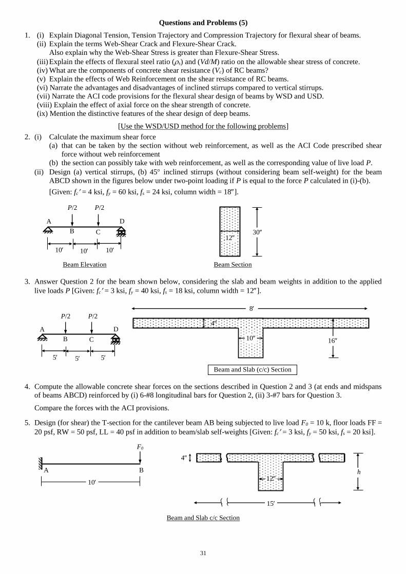
31
Questions and Problems (5)
1. (i) Explain Diagonal Tension, Tension Trajectory and Compression Trajectory for flexural shear of beams.
(ii) Explain the terms Web-Shear Crack and Flexure-Shear Crack.
Also explain why the Web-Shear Stress is greater than Flexure-Shear Stress.
(iii) Explain the effects of flexural steel ratio (s) and (Vd/M) ratio on the allowable shear stress of concrete.
(iv) What are the components of concrete shear resistance (Vc) of RC beams?
(v) Explain the effects of Web Reinforcement on the shear resistance of RC beams.
(vi) Narrate the advantages and disadvantages of inclined stirrups compared to vertical stirrups.
(vii) Narrate the ACI code provisions for the flexural shear design of beams by WSD and USD.
(viii) Explain the effect of axial force on the shear strength of concrete.
(ix) Mention the distinctive features of the shear design of deep beams.
[Use the WSD/USD method for the following problems]
2. (i) Calculate the maximum shear force
(a) that can be taken by the section without web reinforcement, as well as the ACI Code prescribed shear
force without web reinforcement
(b) the section can possibly take with web reinforcement, as well as the corresponding value of live load P.
(ii) Design (a) vertical stirrups, (b) 45 inclined stirrups (without considering beam self-weight) for the beam
ABCD shown in the figures below under two-point loading if P is equal to the force P calculated in (i)-(b).
[Given: fc = 4 ksi, fy = 60 ksi, fs = 24 ksi, column width = 18].
Beam Elevation Beam Section
3. Answer Question 2 for the beam shown below, considering the slab and beam weights in addition to the applied
live loads P [Given: fc = 3 ksi, fy = 40 ksi, fs = 18 ksi, column width = 12].
4. Compute the allowable concrete shear forces on the sections described in Question 2 and 3 (at ends and midspans
of beams ABCD) reinforced by (i) 6-#8 longitudinal bars for Question 2, (ii) 3-#7 bars for Question 3.
Compare the forces with the ACI provisions.
5. Design (for shear) the T-section for the cantilever beam AB being subjected to live load F0 = 10 k, floor loads FF =
20 psf, RW = 50 psf, LL = 40 psf in addition to beam/slab self-weights [Given: fc = 3 ksi, fy = 50 ksi, fs = 20 ksi].
Beam and Slab c/c Section
F0
10
4
15
A B h 12
10
4
Beam and Slab (c/c) Section
16
8
B
5
A D
5
P/2
5
P/2
C
B
10
A D
10
P/2
10
P/2
C 30 12
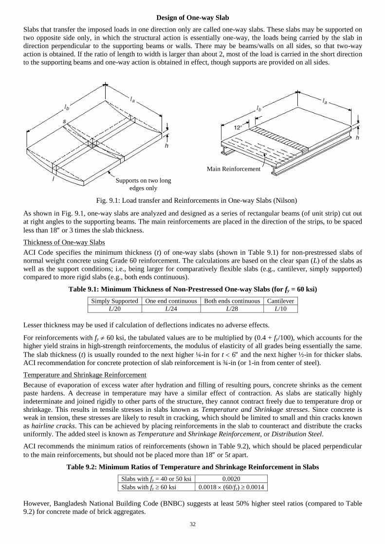
32
Design of One-way Slab
Slabs that transfer the imposed loads in one direction only are called one-way slabs. These slabs may be supported on
two opposite side only, in which the structural action is essentially one-way, the loads being carried by the slab in
direction perpendicular to the supporting beams or walls. There may be beams/walls on all sides, so that two-way
action is obtained. If the ratio of length to width is larger than about 2, most of the load is carried in the short direction
to the supporting beams and one-way action is obtained in effect, though supports are provided on all sides.
As shown in Fig. 9.1, one-way slabs are analyzed and designed as a series of rectangular beams (of unit strip) cut out
at right angles to the supporting beams. The main reinforcements are placed in the direction of the strips, to be spaced
less than 18 or 3 times the slab thickness.
Thickness of One-way Slabs
ACI Code specifies the minimum thickness (t) of one-way slabs (shown in Table 9.1) for non-prestressed slabs of
normal weight concrete using Grade 60 reinforcement. The calculations are based on the clear span (L) of the slabs as
well as the support conditions; i.e., being larger for comparatively flexible slabs (e.g., cantilever, simply supported)
compared to more rigid slabs (e.g., both ends continuous).
Table 9.1: Minimum Thickness of Non-Prestressed One-way Slabs (for fy = 60 ksi)
Simply Supported One end continuous Both ends continuous Cantilever
L/20 L/24 L/28 L/10
Lesser thickness may be used if calculation of deflections indicates no adverse effects.
For reinforcements with fy 60 ksi, the tabulated values are to be multiplied by (0.4 + fy/100), which accounts for the
higher yield strains in high-strength reinforcements, the modulus of elasticity of all grades being essentially the same.
The slab thickness (t) is usually rounded to the next higher ¼-in for t 6 and the next higher ½-in for thicker slabs.
ACI recommendation for concrete protection of slab reinforcement is ¾-in (or 1-in from center of steel).
Temperature and Shrinkage Reinforcement
Because of evaporation of excess water after hydration and filling of resulting pours, concrete shrinks as the cement
paste hardens. A decrease in temperature may have a similar effect of contraction. As slabs are statically highly
indeterminate and joined rigidly to other parts of the structure, they cannot contract freely due to temperature drop or
shrinkage. This results in tensile stresses in slabs known as Temperature and Shrinkage stresses. Since concrete is
weak in tension, these stresses are likely to result in cracking, which should be limited to small and thin cracks known
as hairline cracks. This can be achieved by placing reinforcements in the slab to counteract and distribute the cracks
uniformly. The added steel is known as Temperature and Shrinkage Reinforcement, or Distribution Steel.
ACI recommends the minimum ratios of reinforcements (shown in Table 9.2), which should be placed perpendicular
to the main reinforcements, but should not be placed more than 18 or 5t apart.
Table 9.2: Minimum Ratios of Temperature and Shrinkage Reinforcement in Slabs
Slabs with fy = 40 or 50 ksi 0.0020
Slabs with fy 60 ksi 0.0018 (60/fy) 0.0014
However, Bangladesh National Building Code (BNBC) suggests at least 50% higher steel ratios (compared to Table
9.2) for concrete made of brick aggregates.
Supports on two long
edges only
Main Reinforcement
Fig. 9.1: Load transfer and Reinforcements in One-way Slabs (Nilson)
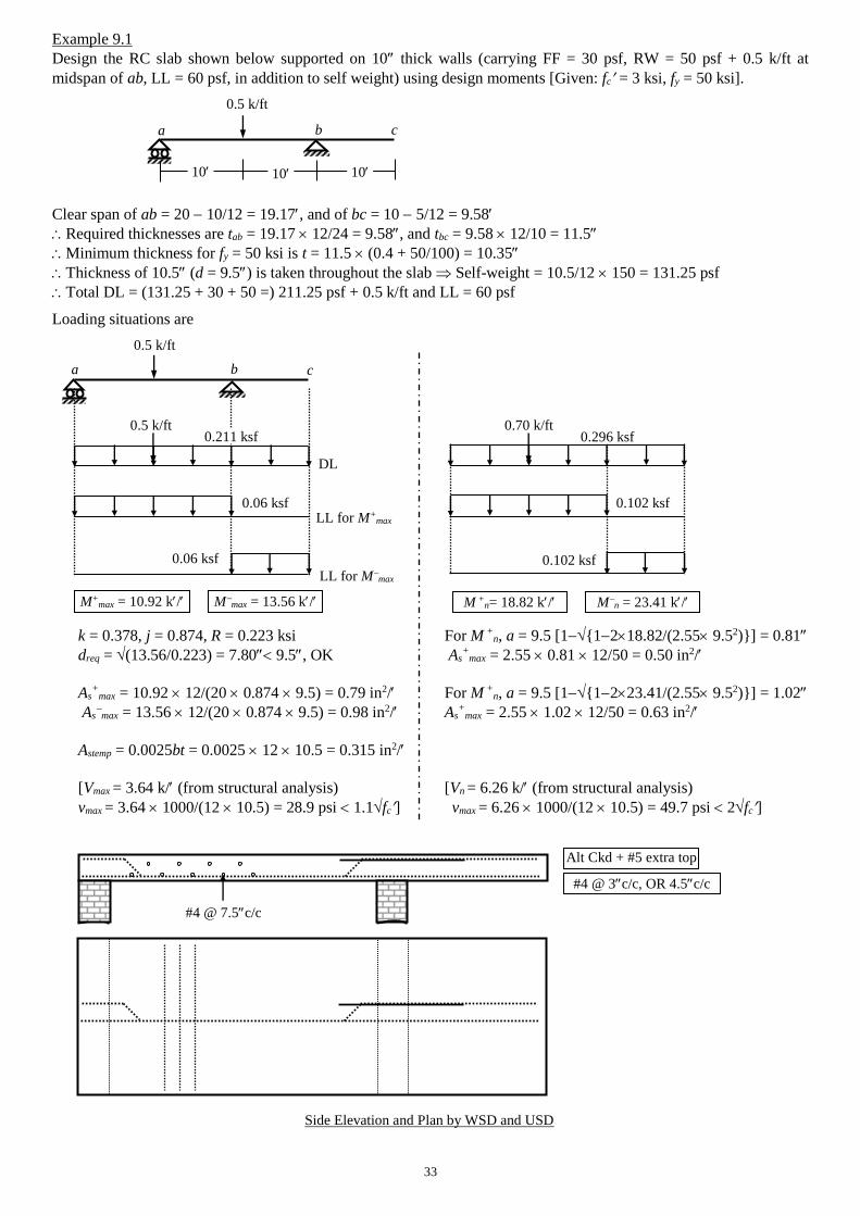
33
Example 9.1
Design the RC slab shown below supported on 10 thick walls (carrying FF = 30 psf, RW = 50 psf + 0.5 k/ft at
midspan of ab, LL = 60 psf, in addition to self weight) using design moments [Given: fc = 3 ksi, fy = 50 ksi].
0.5 k/ft
Clear span of ab = 20 10/12 = 19.17, and of bc = 10 5/12 = 9.58
Required thicknesses are tab = 19.17 12/24 = 9.58, and tbc = 9.58 12/10 = 11.5
Minimum thickness for fy = 50 ksi is t = 11.5 (0.4 + 50/100) = 10.35
Thickness of 10.5 (d = 9.5) is taken throughout the slab Self-weight = 10.5/12 150 = 131.25 psf
Total DL = (131.25 + 30 + 50 =) 211.25 psf + 0.5 k/ft and LL = 60 psf
Loading situations are
0.5 k/ft
0.5 k/ft 0.70 k/ft
k = 0.378, j = 0.874, R = 0.223 ksi For M +
n, a = 9.5 [1{1218.82/(2.55 9.52)}] = 0.81
dreq = (13.56/0.223) = 7.80 9.5, OK As+
max = 2.55 0.81 12/50 = 0.50 in2/
As+
max = 10.92 12/(20 0.874 9.5) = 0.79 in2/ For M +
n, a = 9.5 [1{1223.41/(2.55 9.52)}] = 1.02
As
max = 13.56 12/(20 0.874 9.5) = 0.98 in2/ As+
max = 2.55 1.02 12/50 = 0.63 in2/
Astemp = 0.0025bt = 0.0025 12 10.5 = 0.315 in2/
[Vmax = 3.64 k/ (from structural analysis) [Vn = 6.26 k/ (from structural analysis)
vmax = 3.64 1000/(12 10.5) = 28.9 psi 1.1fc] vmax = 6.26 1000/(12 10.5) = 49.7 psi 2fc]
a b c
10 10 10
a b c
0.06 ksf
DL
LL for M+max
LL for Mmax
M+max = 10.92 k/ M
max = 13.56 k/
0.211 ksf 0.296 ksf
0.102 ksf
0.06 ksf 0.102 ksf
M +
n= 18.82 k/ Mn = 23.41 k/
#4 @ 3c/c, OR 4.5c/c
Alt Ckd + #5 extra top
#4 @ 7.5c/c
Side Elevation and Plan by WSD and USD
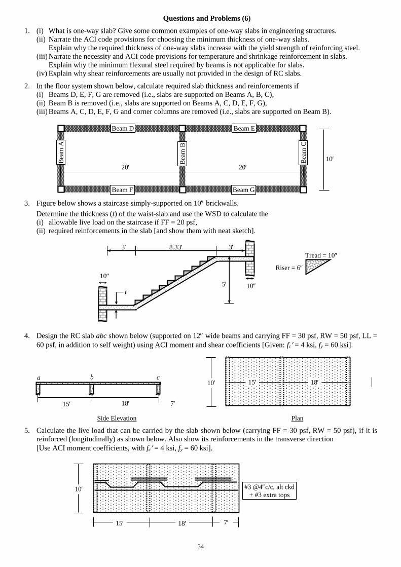
34
Questions and Problems (6)
1. (i) What is one-way slab? Give some common examples of one-way slabs in engineering structures.
(ii) Narrate the ACI code provisions for choosing the minimum thickness of one-way slabs.
Explain why the required thickness of one-way slabs increase with the yield strength of reinforcing steel.
(iii) Narrate the necessity and ACI code provisions for temperature and shrinkage reinforcement in slabs.
Explain why the minimum flexural steel required by beams is not applicable for slabs.
(iv) Explain why shear reinforcements are usually not provided in the design of RC slabs.
2. In the floor system shown below, calculate required slab thickness and reinforcements if
(i) Beams D, E, F, G are removed (i.e., slabs are supported on Beams A, B, C),
(ii) Beam B is removed (i.e., slabs are supported on Beams A, C, D, E, F, G),
(iii) Beams A, C, D, E, F, G and corner columns are removed (i.e., slabs are supported on Beam B).
10
20 20
3. Figure below shows a staircase simply-supported on 10 brickwalls.
Determine the thickness (t) of the waist-slab and use the WSD to calculate the
(i) allowable live load on the staircase if FF = 20 psf,
(ii) required reinforcements in the slab [and show them with neat sketch].
3 8.33 3
Tread = 10
Riser = 6
10
5
t
4. Design the RC slab abc shown below (supported on 12 wide beams and carrying FF = 30 psf, RW = 50 psf, LL =
60 psf, in addition to self weight) using ACI moment and shear coefficients [Given: fc = 4 ksi, fy = 60 ksi].
Side Elevation Plan
5. Calculate the live load that can be carried by the slab shown below (carrying FF = 30 psf, RW = 50 psf), if it is
reinforced (longitudinally) as shown below. Also show its reinforcements in the transverse direction
[Use ACI moment coefficients, with fc = 4 ksi, fy = 60 ksi].
15
a b c
18 7
15 10 18
15
10
18 7
#3 @4c/c, alt ckd
+ #3 extra tops
Bea
m A
Bea
m C
10
Beam D Beam E
Beam F Beam G
Bea
m B
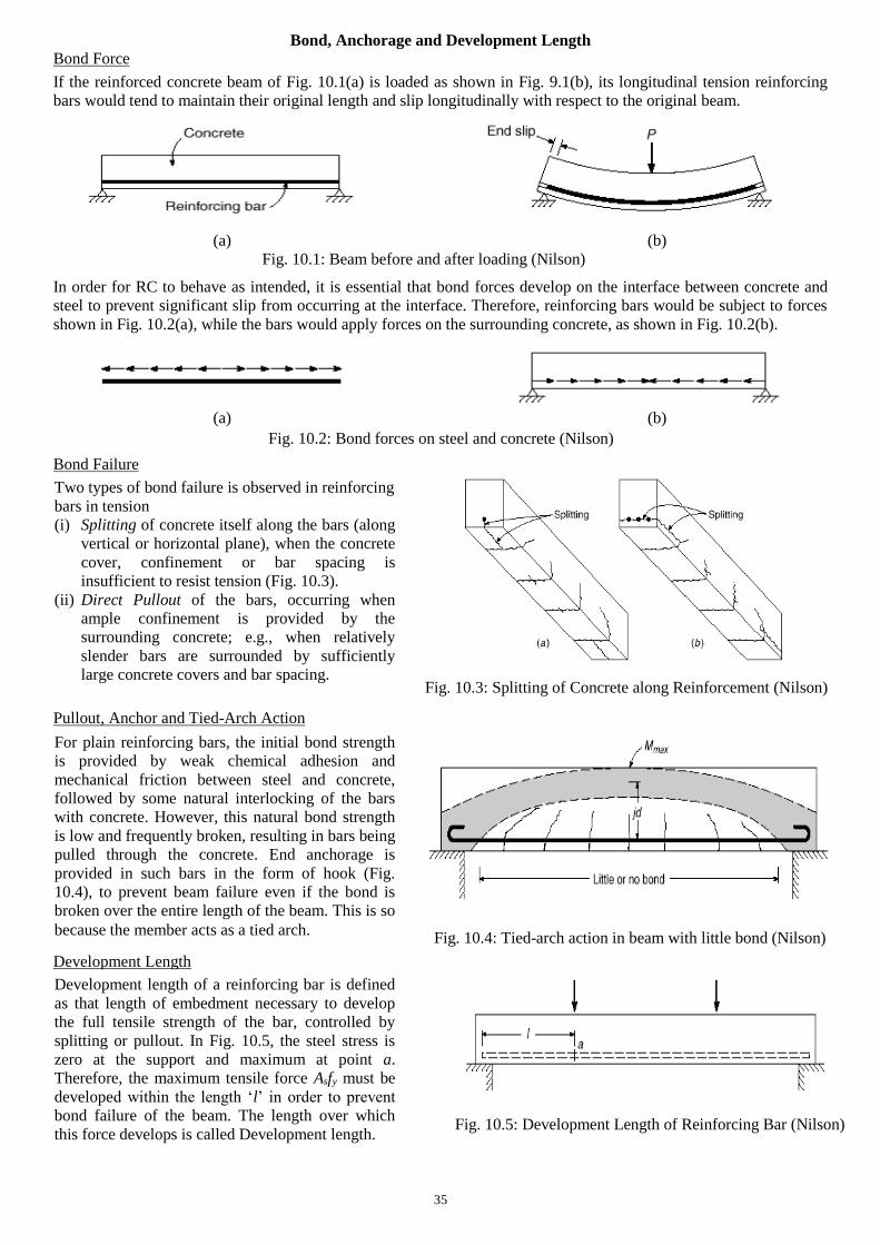
35
Bond, Anchorage and Development Length
Bond Force
If the reinforced concrete beam of Fig. 10.1(a) is loaded as shown in Fig. 9.1(b), its longitudinal tension reinforcing
bars would tend to maintain their original length and slip longitudinally with respect to the original beam.
(a) (b)
In order for RC to behave as intended, it is essential that bond forces develop on the interface between concrete and
steel to prevent significant slip from occurring at the interface. Therefore, reinforcing bars would be subject to forces
shown in Fig. 10.2(a), while the bars would apply forces on the surrounding concrete, as shown in Fig. 10.2(b).
(a) (b)
Bond Failure
Pullout, Anchor and Tied-Arch Action
Development Length
Fig. 10.1: Beam before and after loading (Nilson)
Fig. 10.2: Bond forces on steel and concrete (Nilson)
For plain reinforcing bars, the initial bond strength
is provided by weak chemical adhesion and
mechanical friction between steel and concrete,
followed by some natural interlocking of the bars
with concrete. However, this natural bond strength
is low and frequently broken, resulting in bars being
pulled through the concrete. End anchorage is
provided in such bars in the form of hook (Fig.
10.4), to prevent beam failure even if the bond is
broken over the entire length of the beam. This is so
because the member acts as a tied arch. Fig. 10.4: Tied-arch action in beam with little bond (Nilson)
Two types of bond failure is observed in reinforcing
bars in tension
(i) Splitting of concrete itself along the bars (along
vertical or horizontal plane), when the concrete
cover, confinement or bar spacing is
insufficient to resist tension (Fig. 10.3).
(ii) Direct Pullout of the bars, occurring when
ample confinement is provided by the
surrounding concrete; e.g., when relatively
slender bars are surrounded by sufficiently
large concrete covers and bar spacing.
Fig. 10.3: Splitting of Concrete along Reinforcement (Nilson)
Fig. 10.5: Development Length of Reinforcing Bar (Nilson)
Development length of a reinforcing bar is defined
as that length of embedment necessary to develop
the full tensile strength of the bar, controlled by
splitting or pullout. In Fig. 10.5, the steel stress is
zero at the support and maximum at point a.
Therefore, the maximum tensile force Asfy must be
developed within the length ‘l’ in order to prevent
bond failure of the beam. The length over which
this force develops is called Development length.
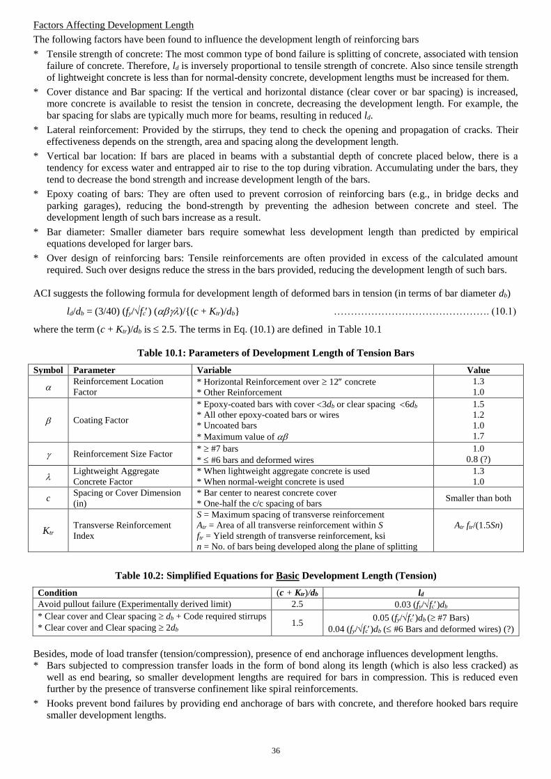
36
Factors Affecting Development Length
The following factors have been found to influence the development length of reinforcing bars
* Tensile strength of concrete: The most common type of bond failure is splitting of concrete, associated with tension
failure of concrete. Therefore, ld is inversely proportional to tensile strength of concrete. Also since tensile strength
of lightweight concrete is less than for normal-density concrete, development lengths must be increased for them.
* Cover distance and Bar spacing: If the vertical and horizontal distance (clear cover or bar spacing) is increased,
more concrete is available to resist the tension in concrete, decreasing the development length. For example, the
bar spacing for slabs are typically much more for beams, resulting in reduced ld.
* Lateral reinforcement: Provided by the stirrups, they tend to check the opening and propagation of cracks. Their
effectiveness depends on the strength, area and spacing along the development length.
* Vertical bar location: If bars are placed in beams with a substantial depth of concrete placed below, there is a
tendency for excess water and entrapped air to rise to the top during vibration. Accumulating under the bars, they
tend to decrease the bond strength and increase development length of the bars.
* Epoxy coating of bars: They are often used to prevent corrosion of reinforcing bars (e.g., in bridge decks and
parking garages), reducing the bond-strength by preventing the adhesion between concrete and steel. The
development length of such bars increase as a result.
* Bar diameter: Smaller diameter bars require somewhat less development length than predicted by empirical
equations developed for larger bars.
* Over design of reinforcing bars: Tensile reinforcements are often provided in excess of the calculated amount
required. Such over designs reduce the stress in the bars provided, reducing the development length of such bars.
ACI suggests the following formula for development length of deformed bars in tension (in terms of bar diameter db)
ld/db = (3/40) (fy/fc) ()/{(c + Ktr)/db} ………………………………………. (10.1)
where the term (c + Ktr)/db is 2.5. The terms in Eq. (10.1) are defined in Table 10.1
Table 10.1: Parameters of Development Length of Tension Bars
Symbol Parameter Variable Value
Reinforcement Location
Factor * Horizontal Reinforcement over 12 concrete
* Other Reinforcement
1.3
1.0
Coating Factor
* Epoxy-coated bars with cover 3db or clear spacing 6db
* All other epoxy-coated bars or wires
* Uncoated bars
* Maximum value of
1.5
1.2
1.0
1.7
Reinforcement Size Factor * #7 bars
* #6 bars and deformed wires
1.0
0.8 (?)
Lightweight Aggregate
Concrete Factor
* When lightweight aggregate concrete is used
* When normal-weight concrete is used
1.3
1.0
c Spacing or Cover Dimension
(in)
* Bar center to nearest concrete cover
* One-half the c/c spacing of bars Smaller than both
Ktr Transverse Reinforcement
Index
S = Maximum spacing of transverse reinforcement
Atr = Area of all transverse reinforcement within S
ftr = Yield strength of transverse reinforcement, ksi
n = No. of bars being developed along the plane of splitting
Atr ftr/(1.5Sn)
Table 10.2: Simplified Equations for Basic Development Length (Tension)
Condition (c + Ktr)/db ld
Avoid pullout failure (Experimentally derived limit) 2.5 0.03 (fy/fc)db
* Clear cover and Clear spacing db + Code required stirrups
* Clear cover and Clear spacing 2db 1.5
0.05 (fy/fc)db ( #7 Bars)
0.04 (fy/fc)db ( #6 Bars and deformed wires) (?)
Besides, mode of load transfer (tension/compression), presence of end anchorage influences development lengths.
* Bars subjected to compression transfer loads in the form of bond along its length (which is also less cracked) as
well as end bearing, so smaller development lengths are required for bars in compression. This is reduced even
further by the presence of transverse confinement like spiral reinforcements.
* Hooks prevent bond failures by providing end anchorage of bars with concrete, and therefore hooked bars require
smaller development lengths.
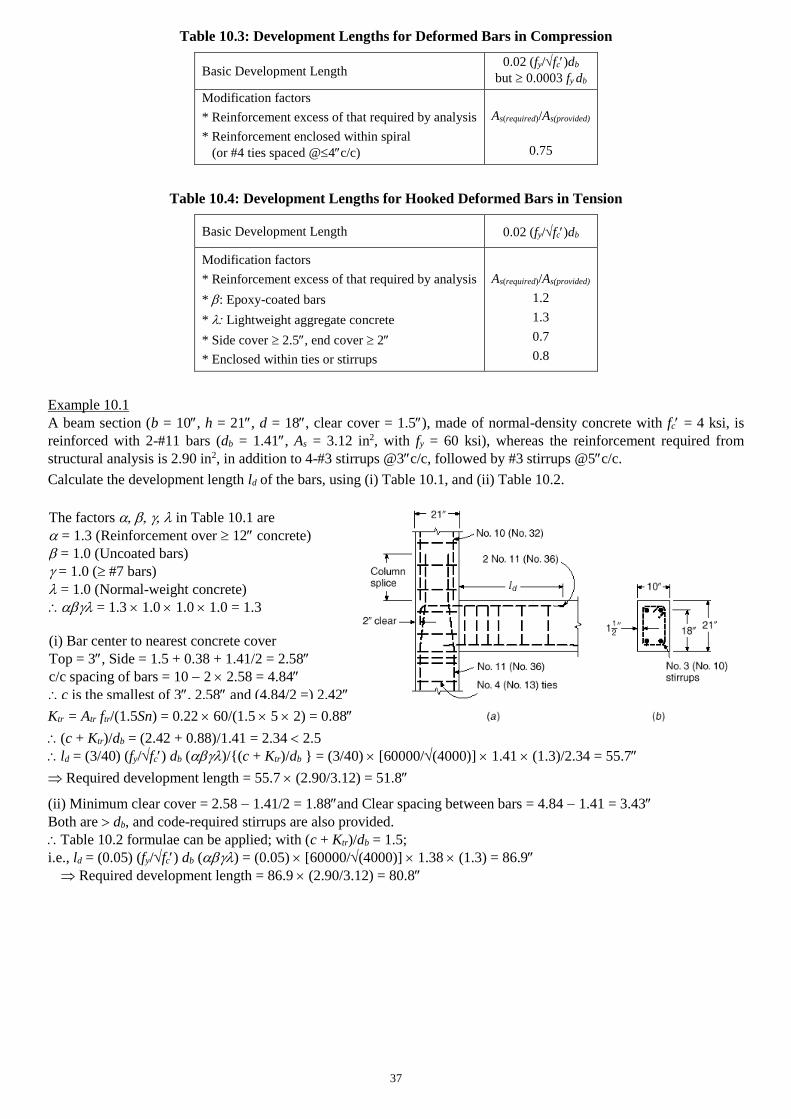
37
Table 10.3: Development Lengths for Deformed Bars in Compression
Basic Development Length 0.02 (fy/fc)db
but 0.0003 fy db
Modification factors
* Reinforcement excess of that required by analysis
* Reinforcement enclosed within spiral
(or #4 ties spaced @4c/c)
As(required)/As(provided)
0.75
Table 10.4: Development Lengths for Hooked Deformed Bars in Tension
Basic Development Length 0.02 (fy/fc)db
Modification factors
* Reinforcement excess of that required by analysis
* : Epoxy-coated bars
* Lightweight aggregate concrete
* Side cover 2.5, end cover 2
* Enclosed within ties or stirrups
As(required)/As(provided)
1.2
1.3
0.7
0.8
Example 10.1
A beam section (b = 10, h = 21, d = 18, clear cover = 1.5), made of normal-density concrete with fc = 4 ksi, is
reinforced with 2-#11 bars (db = 1.41, As = 3.12 in2, with fy = 60 ksi), whereas the reinforcement required from
structural analysis is 2.90 in2, in addition to 4-#3 stirrups @3c/c, followed by #3 stirrups @5c/c.
Calculate the development length ld of the bars, using (i) Table 10.1, and (ii) Table 10.2.
Ktr = Atr ftr/(1.5Sn) = 0.22 60/(1.5 5 2) = 0.88
(c + Ktr)/db = (2.42 + 0.88)/1.41 = 2.34 2.5
ld = (3/40) (fy/fc) db ()/{(c + Ktr)/db } = (3/40) [60000/(4000)] 1.41 (1.3)/2.34 = 55.7
Required development length = 55.7 (2.90/3.12) = 51.8
(ii) Minimum clear cover = 2.58 1.41/2 = 1.88and Clear spacing between bars = 4.84 1.41 = 3.43
Both are db, and code-required stirrups are also provided.
Table 10.2 formulae can be applied; with (c + Ktr)/db = 1.5;
i.e., ld = (0.05) (fy/fc) db () = (0.05) [60000/(4000)] 1.38 (1.3) = 86.9
Required development length = 86.9 (2.90/3.12) = 80.8
The factors in Table 10.1 are
= 1.3 (Reinforcement over 12 concrete)
= 1.0 (Uncoated bars)
= 1.0 ( #7 bars)
= 1.0 (Normal-weight concrete)
= 1.3 1.0 1.0 1.0 = 1.3
(i) Bar center to nearest concrete cover
Top = 3, Side = 1.5 + 0.38 + 1.41/2 = 2.58
c/c spacing of bars = 10 2 2.58 = 4.84
c is the smallest of 3, 2.58 and (4.84/2 =) 2.42
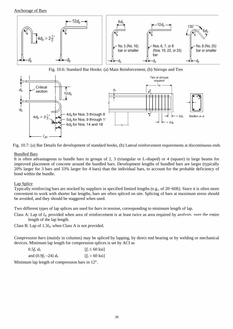
38
Anchorage of Bars
Bundled Bars
It is often advantageous to bundle bars in groups of 2, 3 (triangular or L-shaped) or 4 (square) in large beams for
improved placement of concrete around the bundled bars. Development lengths of bundled bars are larger (typically
20% larger for 3 bars and 33% larger for 4 bars) than the individual bars, to account for the probable deficiency of
bond within the bundle.
Lap Splice
Typically reinforcing bars are stocked by suppliers in specified limited lengths (e.g., of 20~60ft). Since it is often more
convenient to work with shorter bar lengths, bars are often spliced on site. Splicing of bars at maximum stress should
be avoided, and they should be staggered when used.
Two different types of lap splices are used for bars in tension, corresponding to minimum length of lap.
Class A: Lap of ld, provided when area of reinforcement is at least twice as area required by analysis, over the entire
length of the lap length.
Class B: Lap of 1.3ld, when Class A is not provided.
Compression bars (mainly in columns) may be spliced by lapping, by direct end bearing or by welding or mechanical
devices. Minimum lap length for compression splices is set by ACI as
0.5fy db [fy 60 ksi]
and (0.9fy 24) db [fy 60 ksi]
Minimum lap length of compression bars in 12.
Fig. 10.7: (a) Bar Details for development of standard hooks, (b) Lateral reinforcement requirements at discontinuous ends
Fig. 10.6: Standard Bar Hooks: (a) Main Reinforcement, (b) Stirrups and Ties
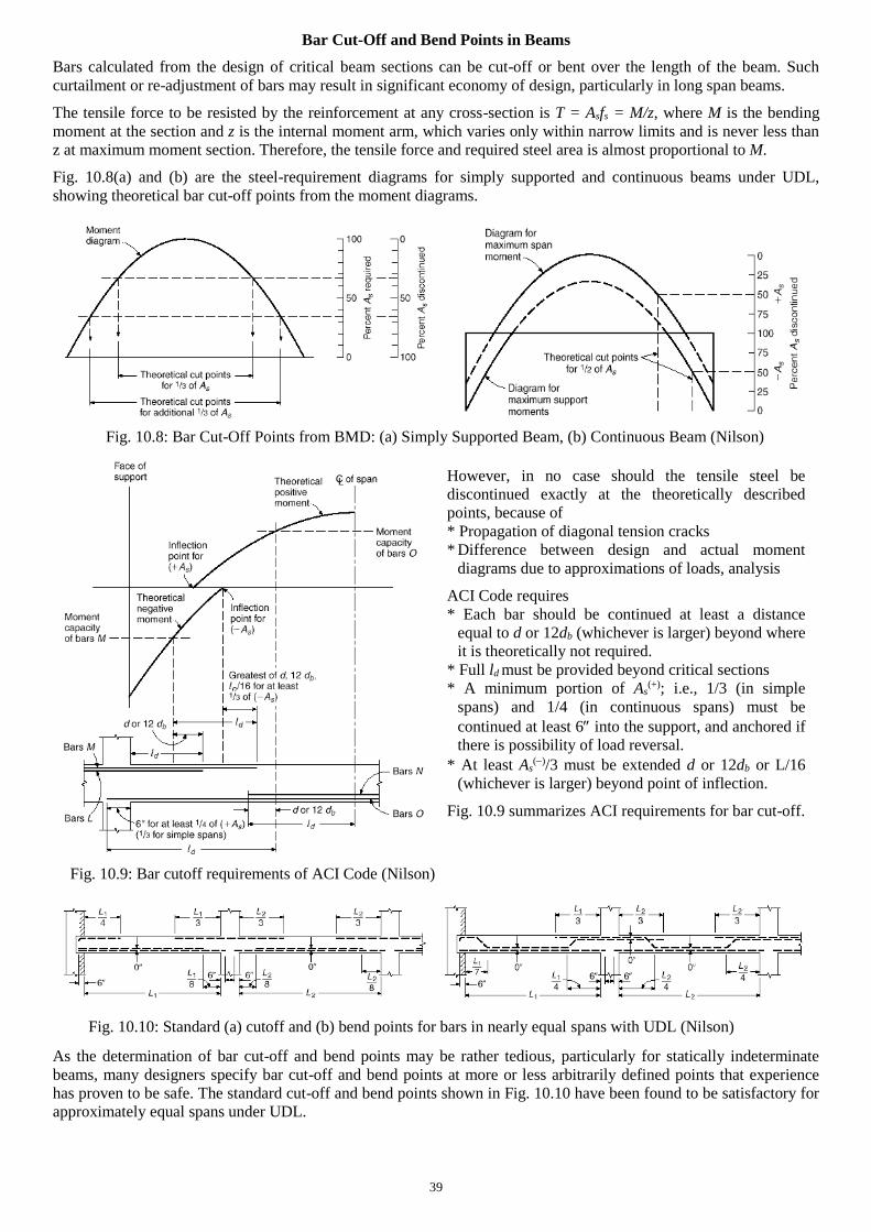
39
Bar Cut-Off and Bend Points in Beams
Bars calculated from the design of critical beam sections can be cut-off or bent over the length of the beam. Such
curtailment or re-adjustment of bars may result in significant economy of design, particularly in long span beams.
The tensile force to be resisted by the reinforcement at any cross-section is T = Asfs = M/z, where M is the bending
moment at the section and z is the internal moment arm, which varies only within narrow limits and is never less than
z at maximum moment section. Therefore, the tensile force and required steel area is almost proportional to M.
Fig. 10.8(a) and (b) are the steel-requirement diagrams for simply supported and continuous beams under UDL,
showing theoretical bar cut-off points from the moment diagrams.
As the determination of bar cut-off and bend points may be rather tedious, particularly for statically indeterminate
beams, many designers specify bar cut-off and bend points at more or less arbitrarily defined points that experience
has proven to be safe. The standard cut-off and bend points shown in Fig. 10.10 have been found to be satisfactory for
approximately equal spans under UDL.
Fig. 10.9: Bar cutoff requirements of ACI Code (Nilson)
Fig. 10.8: Bar Cut-Off Points from BMD: (a) Simply Supported Beam, (b) Continuous Beam (Nilson)
However, in no case should the tensile steel be
discontinued exactly at the theoretically described
points, because of
* Propagation of diagonal tension cracks
* Difference between design and actual moment
diagrams due to approximations of loads, analysis
ACI Code requires
* Each bar should be continued at least a distance
equal to d or 12db (whichever is larger) beyond where
it is theoretically not required.
* Full ld must be provided beyond critical sections
* A minimum portion of As(+); i.e., 1/3 (in simple
spans) and 1/4 (in continuous spans) must be
continued at least 6 into the support, and anchored if
there is possibility of load reversal.
* At least As()/3 must be extended d or 12db or L/16
(whichever is larger) beyond point of inflection.
Fig. 10.9 summarizes ACI requirements for bar cut-off.
Fig. 10.10: Standard (a) cutoff and (b) bend points for bars in nearly equal spans with UDL (Nilson)
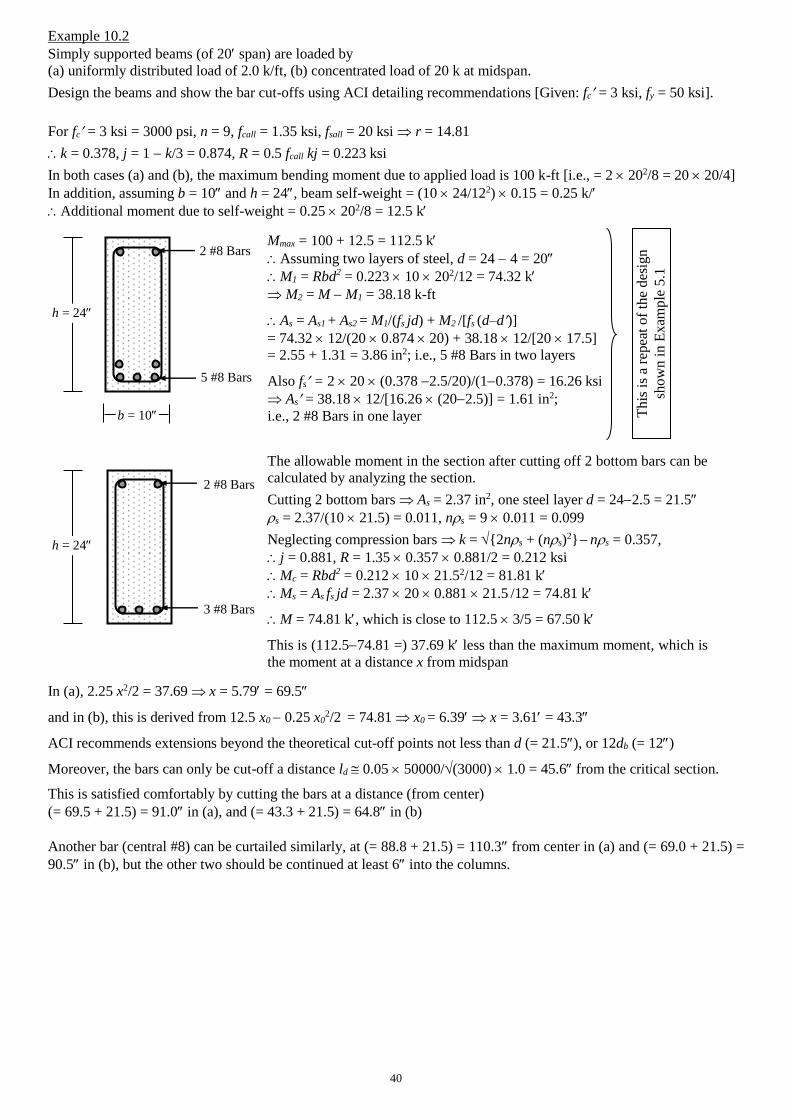
40
Example 10.2
Simply supported beams (of 20 span) are loaded by
(a) uniformly distributed load of 2.0 k/ft, (b) concentrated load of 20 k at midspan.
Design the beams and show the bar cut-offs using ACI detailing recommendations [Given: fc = 3 ksi, fy = 50 ksi].
For fc = 3 ksi = 3000 psi, n = 9, fcall = 1.35 ksi, fsall = 20 ksi r = 14.81
k = 0.378, j = 1 k/3 = 0.874, R = 0.5 fcall kj = 0.223 ksi
In both cases (a) and (b), the maximum bending moment due to applied load is 100 k-ft [i.e., = 2 202/8 = 20 20/4]
In addition, assuming b = 10 and h = 24, beam self-weight = (10 24/122) 0.15 = 0.25 k/
Additional moment due to self-weight = 0.25 202/8 = 12.5 k
In (a), 2.25 x2/2 = 37.69 x = 5.79 = 69.5
and in (b), this is derived from 12.5 x0 0.25 x02/2 = 74.81 x0 = 6.39 x = 3.61 = 43.3
ACI recommends extensions beyond the theoretical cut-off points not less than d (= 21.5), or 12db (= 12)
Moreover, the bars can only be cut-off a distance ld 0.05 50000/(3000) 1.0 = 45.6 from the critical section.
This is satisfied comfortably by cutting the bars at a distance (from center)
(= 69.5 + 21.5) = 91.0 in (a), and (= 43.3 + 21.5) = 64.8 in (b)
Another bar (central #8) can be curtailed similarly, at (= 88.8 + 21.5) = 110.3 from center in (a) and (= 69.0 + 21.5) =
90.5 in (b), but the other two should be continued at least 6 into the columns.
h = 24
b = 10
5 #8 Bars
2 #8 Bars Mmax = 100 + 12.5 = 112.5 k
Assuming two layers of steel, d = 24 4 = 20
M1 = Rbd2 = 0.223 10 202/12 = 74.32 k
M2 = M M1 = 38.18 k-ft
As = As1 + As2 = M1/(fs jd) + M2 /[fs (d–d)]
= 74.32 12/(20 0.874 20) + 38.18 12/[20 17.5]
= 2.55 + 1.31 = 3.86 in2; i.e., 5 #8 Bars in two layers
Also fs = 2 20 (0.378 2.5/20)/(10.378) = 16.26 ksi
As = 38.18 12/[16.26 (202.5)] = 1.61 in2;
i.e., 2 #8 Bars in one layer Th
is i
s a
repea
t o
f th
e d
esig
n
sho
wn
in
Ex
amp
le 5
.1
3 #8 Bars
2 #8 Bars
The allowable moment in the section after cutting off 2 bottom bars can be
calculated by analyzing the section.
Cutting 2 bottom bars As = 2.37 in2, one steel layer d = 242.5 = 21.5
s= 2.37/(10 21.5) = 0.011,ns= 9 0.011 = 0.099
Neglecting compression bars k = {2ns+ (ns)2} ns = 0.357,
j = 0.881, R = 1.35 0.357 0.881/2 = 0.212 ksi
Mc = Rbd2 = 0.212 10 21.52/12 = 81.81 k
Ms = As fs jd = 2.37 20 0.881 21.5 /12 = 74.81 k
M = 74.81 k, which is close to 112.5 3/5 = 67.50 k
This is (112.574.81 =) 37.69 k less than the maximum moment, which is
the moment at a distance x from midspan
h = 24
41
Questions and Problems (7)
1. (i) What is development length? Mention the factors influencing development length of deformed bars in tension.
(ii) Briefly compare between the development lengths of
(a) Bottom and top bars, (b) Epoxy-coated and uncoated bars, (c) Large diameter and small diameter bars.
(iii) Explain the effects of concrete tensile strength, cover distance and lightweight aggregate on the development
length in tension.
(iv) Explain why the development length of compression bars is smaller than that of tension bars.
(v) Narrate the necessity of hook and anchorage for plain and deformed bars.
(vi) What are bar splices? Distinguish between lap splices in tension and compression.
(vii) Explain why flexural reinforcement bars are not cut off exactly where they are not theoretically required.
Also justify the difference among the approximate bar cut-off points (at Ln/3, Ln/4, Ln/7, Ln/8 from supports).
2. The tensile flexural reinforcement required in the cantilever beam shown below is As = 2.80 in2, which is provided
by two #11 bars (for d = 21), while #3 transverse reinforcements with 1.5 cover are provided starting at 4 from
column face, with 3 @ 8c/c and 5 @ 10c/c.
Check if the #11 bars (shown in figure below) are provided adequate
(a) development length in the beam, (b) embedment within the column [Given: fc = 4 ksi, fy = 50 ksi].
3. Rework Question 2 using 4 #8 (instead of 2 #11) bars.
4.
5. Simply supported beams (of 20 span) are loaded by
(a) uniformly distributed load of 2.0 k/ft, (b) concentrated load of 20 k at midspan.
Design the beams and show the bar cut-offs using ACI detailing recommendations [Given: fc = 3 ksi, fy = 50 ksi].
12
18 96 20
Calculate the
(a) Development length Ld and lap splice Lp for the column-footing
connection (under compression) shown on left, if all the column bars
are #7.
(b) Minimum required thickness (tf) of the footing
(c) Maximum footing bar size if width (Bf) of the footing is 6
[Given: bc = 18, fc = 4 ksi, fy = 50 ksi].
Lp
Ld tf
Bf
bc
#3
@ 6
c/c

42
Following are some of the theoretical questions discussed after midterm exam, with guidelines for their answers.
The examination questions can be different or mixed or parts (based on the same topics/concepts).
Don’t copy this language, just follow the points and read books to prepare your own answers.
1. Mention the differences and advantages of designing beams as T-beams compared to rectangular beams.
Effective width (beff) in T-beam determined from three conditions.
Large beff provide large compression area, therefore compression rarely governs in T-beams.
Also smaller depths may be provided because of the larger beff.
2. Explain the differences between flexural stress distribution over T- and rectangular beams (and their effects).
Two-dimensional stress distribution due to tension/compression from slab (effect on fc).
Variation of stresses across the width of beam due to shear deformations (effect on beff).
3. Mention and explain the ACI-recommended effective widths of T- and L-Beams.
Variation of stress across the width of the beams.
Mention the T-beam widths and L-beam widths.
4. Explain Diagonal Tension, Tension Trajectory and Compression Trajectory for flexural shear of beams.
Shear failure of RC, is more properly called Diagonal Tension Failure due to the mode of failure, i.e., as the
principal tensile stress that acts diagonally (provide Figures).
Tension Trajectory is the curve joining the directions of maximum diagonal tensile stress in a beam, while
Compression Trajectory is the curve joining the directions of maximum compressive stress.
5. Explain Web-Shear crack and Flexure-Shear crack. Also explain which is greater.
Web-Shear crack is due to diagonal tension from maximum shear.
Flexure-Shear crack is due to diagonal tension following initial crack from maximum moment.
Flexure-Shear crack is smaller because the cracked (and smaller) section involved.
6. Explain the effects of flexural steel ratio (s) and (Vd/M) ratio on the allowable shear stress of concrete.
Flexural steel leads to smaller and narrower flexural cracks, leaving a larger uncracked concrete area to resist
shear, and increasing shear resistance of section.
Stress where diagonal cracks develop depends on ratio of shear and flexural stress, i.e., proportional to Vd/M.
Mention the formula with upper limit representing web-shear crack.
7. Explain the effects of Web Reinforcement on the shear resistance of RC beams.
Mention concrete shear resistance components due to uncracked concrete (Vcz), interlocking across crack (Viy)
and dowel action (Vd).
Web Reinforcements enhance beam shear resistance after the formation of diagonal cracks, by
restricting lengthening of diagonal cracks into concrete compression zone (thereby increasing Vcz),
restricting widening of cracks (thereby increasing the interface force Viy),
confining the longitudinal bars (thereby resisting their splitting and increasing dowel action force Vd),
most importantly, by resisting the external shear force by an additional force Vs.
8. Narrate the advantages and disadvantages of inclined stirrups compared to vertical stirrups.
Inclined stirrups are more efficient, acting perpendicular to diagonal tension crack, allowing wider spacing.
Are more difficult to construct and can be vulnerable/ineffective for reversible loading.
9. Narrate the ACI code provisions for the flexural shear design of beams by WSD and USD.
For both methods, mention
Vext and Vn.
Vc, Vc1 and Vc2.
Allowable maximum and minimum spacing.
10. Explain the effect of axial force on the shear strength of concrete.
Qualitatively explain how normal force (compression/tension) effects frictional (shear) resistance.
Mention the formulae with graph showing vc vs. N/Ag.
11. Mention the distinctive features of the shear design of deep beams.
For deep and normal beams, mention
vc, vn, and Avh
12. What is one-way slab? Give some common examples of one-way slabs in engineering structures.
Slab where loads are transferred in one direction only.
Obviously if supports are in one direction, but span ratios and support stiffness may transfer much of the load
in one direction, approximating one-way action.
Examples include slab bridge/culvert, garage, balcony, porch, staircase, etc.
43
13. Narrate the ACI code provisions for choosing the minimum thickness of one-way slabs. Explain why the required
thickness of one-way slabs increase with the yield strength of reinforcing steel.
Mention the provisions (considering deflections) depending on support conditions.
Since Es is almost constant, stronger steels have larger yield strains and deflections, requiring thicker slabs.
14. Narrate the necessity and ACI code provisions for temperature and shrinkage reinforcement in slabs. Explain why
the minimum flexural steel required by beams is not applicable for slabs.
Temperature drop and loss of water results in concrete volume reduction. Adjoining structural elements and
supports tend to check the reduction, creating tension in concrete and crack formation.
Temperature and shrinkage reinforcements tend to check the cracks, keeping them to hairline cracks.
Mention the formulae (ACI for stone, BNBC for brick aggregate) and maximum spacing.
Minimum flexural steel for beams is not applicable for slabs, which are two-dimensional, much larger in size
and often statically indeterminate.
15. Explain why shear reinforcements are usually not provided in the design of RC slabs.
Slab thickness based on serviceability (deflections) requirements is often large enough for flexural shear.
Shear reinforcements are difficult to place in slabs.
16. What is development length? Explain the factors influencing development length of deformed bars in tension.
The length of embedment necessary to develop the full tensile strength of the bar.
Factors include
Bar diameter and Yield strength of steel: Larger bars and stronger steel require larger tensile forces in steel,
which requires larger ld to be transferred to concrete.
Moreover, smaller bars require less ld than predicted by empirical equations developed for larger bars.
Tensile strength of concrete: The most common type of bond failure is splitting of concrete, associated with
tension failure of concrete. Therefore, ld is inversely proportional to tensile strength of concrete.
Cover distance and Bar spacing: If concrete clear cover or bar spacing is increased, more concrete is
available to resist the tension, decreasing the development length.
Lateral reinforcement: Provided by stirrups, they tend to check the opening and propagation of cracks.
Their effectiveness depends on the strength, area and spacing along the development length.
Bar location: Bars on substantial concrete require more ld due to tendency for excess water and entrapped air
to rise to the top during vibration.
Bar coating: Often used to prevent corrosion of reinforcing bars, they reduce the bond-strength by
preventing the adhesion between concrete and steel. Development length of such bars increase as a result.
Type of concrete: Since tensile strength of lightweight concrete is less than for normal-density concrete,
development lengths must be increased for them
17. Explain why the development length of compression bars is smaller than that of tension bars.
Bars subjected to compression transfer loads in the form of bond along its length as well as end bearing.
Bond is also better along bar length, because concrete is less cracked than in tension.
18. Narrate the necessity of hook and anchorage for plain and deformed bars.
Hooks prevent bond failures by providing end anchorage of bars with concrete.
Provide almost the entire bond for plain bars, through ‘tied-arch action’.
19. What are bar splices? Distinguish between lap splices in tension and compression.
Since it is often more convenient to work with shorter bar lengths, bars are often spliced on site. Splicing of
bars at maximum stress should be avoided, and they should be staggered when used.
Two different types of lap splices (Class A and B) are used for bars in tension, corresponding to minimum
length of lap, depending on area of reinforcement compared to area required by analysis.
Minimum lap length for compression splices depends on steel strength.
Mention formulae for both tension and compression splices.
20. Explain why flexural reinforcement bars are not cut off exactly where they are not theoretically required.
Also justify the difference among the approximate bar cut-off points (at Ln/3, Ln/4, Ln/7, Ln/8 from supports).
Tensile steel should never be discontinued exactly at the theoretically described points, because of
Propagation of diagonal tension cracks.
Difference between design and actual moment diagrams due to approximations of loads and analysis.
For uniformly distributed beams of nearly equal spans
Ln/3 approximates negative bar cut-off point for continuous ends (large moments) and Ln/4 for
discontinuous ends (less or almost no moment)
Ln/4 approximates crank locations for continuous ends and Ln/7 for discontinuous ends, which are smaller
than cut-off distances as no extension or ld is involved.
Ln/8 approximates the point where about 50% positive bars can be cut-off, considering extension.
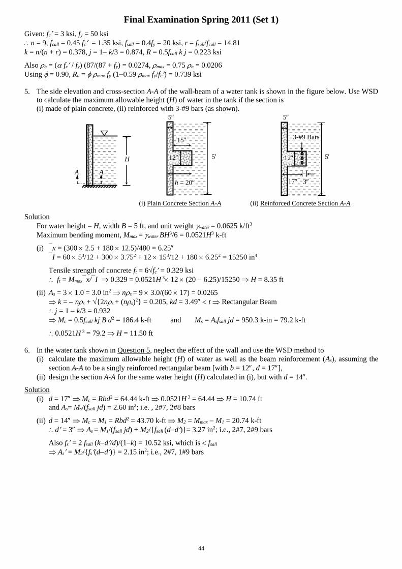
44
Final Examination Spring 2011 (Set 1)
Given: fc = 3 ksi, fy = 50 ksi
n = 9, fcall = 0.45 fc = 1.35 ksi, fsall = 0.4fy = 20 ksi, r = fsall/fcall = 14.81
k = n/(n + r) = 0.378, j = 1 k/3 = 0.874, R = 0.5fcall k j = 0.223 ksi
Also b = ( fc / fy)(87/(87 + fy) = 0.0274, max = 0.75 b = 0.0206
Using = 0.90, Ru = maxfy (10.59maxfy/fc) = 0.739 ksi
5. The side elevation and cross-section A-A of the wall-beam of a water tank is shown in the figure below. Use WSD
to calculate the maximum allowable height (H) of water in the tank if the section is
(i) made of plain concrete, (ii) reinforced with 3-#9 bars (as shown). 5 5
5 5
A
(i) Plain Concrete Section A-A (ii) Reinforced Concrete Section A-A
Solution
For water height = H, width B = 5 ft, and unit weight water = 0.0625 k/ft3
Maximum bending moment, Mmax = water BH3/6 = 0.0521H3 k-ft
(i) x = (300 2.5 + 180 12.5)/480 = 6.25
I = 60 53/12 + 300 3.752 + 12 153/12 + 180 6.252 = 15250 in4
Tensile strength of concrete ft = 6fc = 0.329 ksi
ft = Mmaxx/I 0.329 = 0.0521H 3 12 (20 6.25)/15250 H = 8.35 ft
(ii) As = 3 1.0 = 3.0 in2 ns = 9 3.0/(60 17) = 0.0265
k = ns + {2ns + (ns)2} = 0.205, kd = 3.49 t Rectangular Beam
j = 1 k/3 = 0.932
Mc = 0.5fcall kj B d2 = 186.4 k-ft and Ms = Asfsall jd = 950.3 k-in = 79.2 k-ft
0.0521H 3 = 79.2 H = 11.50 ft
6. In the water tank shown in Question 5, neglect the effect of the wall and use the WSD method to
(i) calculate the maximum allowable height (H) of water as well as the beam reinforcement (As), assuming the
section A-A to be a singly reinforced rectangular beam [with b = 12, d = 17],
(ii) design the section A-A for the same water height (H) calculated in (i), but with d = 14.
Solution
(i) d = 17 Mc = Rbd2 = 64.44 k-ft 0.0521H 3 = 64.44 H = 10.74 ft
and As= Ms/(fsall jd) = 2.60 in2; i.e. , 2#7, 2#8 bars
(ii) d = 14 Mc = M1 = Rbd2 = 43.70 k-ft M2 = Mmax M1 = 20.74 k-ft
d = 3 As = M1/(fsall jd) + M2/{fsall (dd)}= 3.27 in2; i.e., 2#7, 2#9 bars
Also fs = 2 fsall (kd/d)/(1k) = 10.52 ksi, which is fsall
As = M2/{fs(dd)} = 2.15 in2; i.e., 2#7, 1#9 bars
H
A
12
15
h = 20 17
12
3
3-#9 Bars
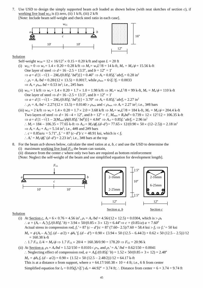
45
7. Use USD to design the simply supported beam acb loaded as shown below (with neat sketches of section c), if
working live load wLL is (i) zero, (ii) 1 k/ft, (iii) 2 k/ft
[Note: Include beam self-weight and check steel ratio in each case].
wLL
a b
c 16
10 10
12
Solution
Self-weight wSW = 12 16/122 0.15 = 0.20 k/ft and span L = 20 ft
(i) wLL = 0 wu = 1.4 0.20 = 0.28 k/ft Mu= wuL2/8 = 14 k-ft, Mn = Mu/ = 15.56 k-ft
One layer of steel d = 16 2.5 = 13.5, and b = 12 = 1
a = d [1 {1 2Mn/(0.85fc bd2)}] = 0.46 As = 0.85fc ab/fy = 0.28 in2
s = As /bd = 0.28/(12 13.5) = 0.0017, while min = 6fc/fy = 0.0033
As = min bd = 0.53 in2; i.e., 2#5 bars
(ii) wLL = 1 k/ft wu = 1.4 0.20 + 1.7 1.0 = 1.98 k/ft Mu= wuL2/8 = 99 k-ft, Mn = Mu/ = 110 k-ft
One layer of steel d = 16 2.5 = 13.5, and b = 12 = 1
a = d [1 {1 2Mn/(0.85fc bd2)}] = 3.70 As = 0.85fc ab/fy = 2.27 in2
s = As /bd = 2.27/(12 13.5) = 0.0140 min and max As = 2.27 in2; i.e., 3#8 bars
(iii) wLL = 2 k/ft wu = 1.4 0.20 + 1.7 2.0 = 3.68 k/ft Mu= wuL2/8 = 184 k-ft, Mn = Mu/ = 204.4 k-ft
Two layers of steel d = 16 4 = 12, and b = 12 = 1, Mmax = Rubd2= 0.739 12 122/12 = 106.35 k-ft
a = d [1 {1 2(Mmax/)(0.85fc bd2)}] = 4.84 As1 = 0.85fc ab/fy = 2.96 in2
M2 = 184 106.35 = 77.65 k-ft As2 = M2/fy (dd) = 77.65 12/(0.90 50 (122.5)) = 2.18 in2
As = As1 + As2 = 5.14 in2; i.e., 4#8 and 2#9 bars
c = 0.85a/ = 5.71, fs = 87 (cd)/ c = 48.91 ksi, which is fy
As = M2/fs (dd) = 2.23 in2; i.e., 3#8 bars at the top
8. For the beam acb shown below, calculate the steel ratios at a, b, c and use the USD to determine the
(i) maximum working live load FLL the beam can sustain,
(ii) distance from the center c where only two bars are required as bottom reinforcement
[Note: Neglect the self-weight of the beam and use simplified equation for development length].
FLL
a b 2-16mm 2-16mm
c 10
6-25mm
10 10 2-25mm
12 12
Section a, b Section c
Solution
(i) At Section c, As = 6 0.76 = 4.56 in2, s = As /bd = 4.56/(12 12.5) = 0.0304, which is b
a = (As As) fy/(0.85fc b) = 3.94 50/(0.85 3 12) = 6.44 c = (0.85/) a = 7.60
Actual stress in compression rod, fs = 87 (c d)/c = 87 (7.60 2.5)/7.60 = 58.4 ksi fy fs = 50 ksi
Mu = (As As) fy (d a/2) + As fy (d d) = 0.90 {3.94 50 (12.5 6.44/2) + 0.62 50 (12.5 2.5)}/12
= 160.38 k-ft
1.7 FLL L/4 = Mu/ 1.7 FLL 20/4 = 160.38/0.90 = 178.20 FLL = 20.96 k
(ii) At Section a, s = As/bd = 1.52/150 = 0.0101 b, and s = As /bd = 0.62/150 = 0.0041
Neglecting effect of compression rod, a = Asfy/(0.85fc b) = 1.52 50/(0.85 3 12) = 2.48
Mu = As fy (d a/2) = 0.90 {1.52 50 (12.5 2.48/2)}/12 = 64.17 k-ft
This is at a distance x from support, where x = 64.17/160.38 10 = 4 ft; i.e., 6 ft from center
Simplified equation for ld = 0.05(fy/fc) db = 44.92 = 3.74 ft; Distance from center = 6 + 3.74 = 9.74 ft
2.5
2.5
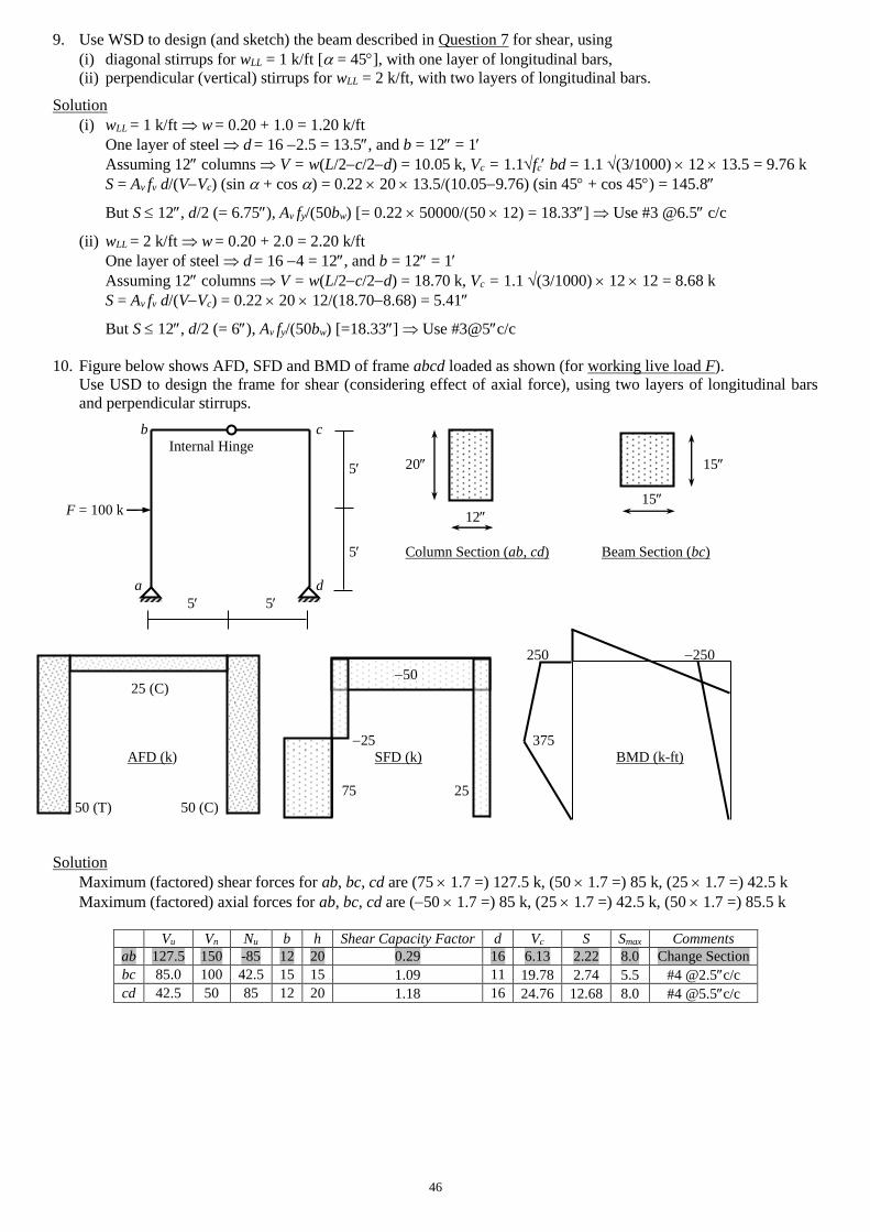
46
9. Use WSD to design (and sketch) the beam described in Question 7 for shear, using
(i) diagonal stirrups for wLL = 1 k/ft [ = 45], with one layer of longitudinal bars,
(ii) perpendicular (vertical) stirrups for wLL = 2 k/ft, with two layers of longitudinal bars.
Solution
(i) wLL = 1 k/ft w = 0.20 + 1.0 = 1.20 k/ft
One layer of steel d = 16 2.5 = 13.5, and b = 12 = 1
Assuming 12 columns V = w(L/2c/2d) = 10.05 k, Vc = 1.1fc bd = 1.1 (3/1000) 12 13.5 = 9.76 k
S = Av fv d/(VVc) (sin + cos ) = 0.22 20 13.5/(10.059.76) (sin 45 + cos 45) = 145.8
But S 12, d/2 (= 6.75), Av fy/(50bw) [= 0.22 50000/(50 12) = 18.33] Use #3 @6.5 c/c
(ii) wLL = 2 k/ft w = 0.20 + 2.0 = 2.20 k/ft
One layer of steel d = 16 4 = 12, and b = 12 = 1
Assuming 12 columns V = w(L/2c/2d) = 18.70 k, Vc = 1.1 (3/1000) 12 12 = 8.68 k
S = Av fv d/(VVc) = 0.22 20 12/(18.708.68) = 5.41
But S 12, d/2 (= 6), Av fy/(50bw) [=18.33] Use #3@5c/c
10. Figure below shows AFD, SFD and BMD of frame abcd loaded as shown (for working live load F).
Use USD to design the frame for shear (considering effect of axial force), using two layers of longitudinal bars
and perpendicular stirrups.
b c
Internal Hinge
20 15
15
12
5 Column Section (ab, cd) Beam Section (bc)
a d
5 5
250 250
25 (C)
25 375
AFD (k) SFD (k) BMD (k-ft)
75 25
50 (T) 50 (C)
Solution
Maximum (factored) shear forces for ab, bc, cd are (75 1.7 =) 127.5 k, (50 1.7 =) 85 k, (25 1.7 =) 42.5 k
Maximum (factored) axial forces for ab, bc, cd are (50 1.7 =) 85 k, (25 1.7 =) 42.5 k, (50 1.7 =) 85.5 k
Vu Vn Nu b h Shear Capacity Factor d Vc S Smax Comments
ab 127.5 150 -85 12 20 0.29 16 6.13 2.22 8.0 Change Section
bc 85.0 100 42.5 15 15 1.09 11 19.78 2.74 5.5 #4 @2.5c/c
cd 42.5 50 85 12 20 1.18 16 24.76 12.68 8.0 #4 @5.5c/c
50
F = 100 k
5
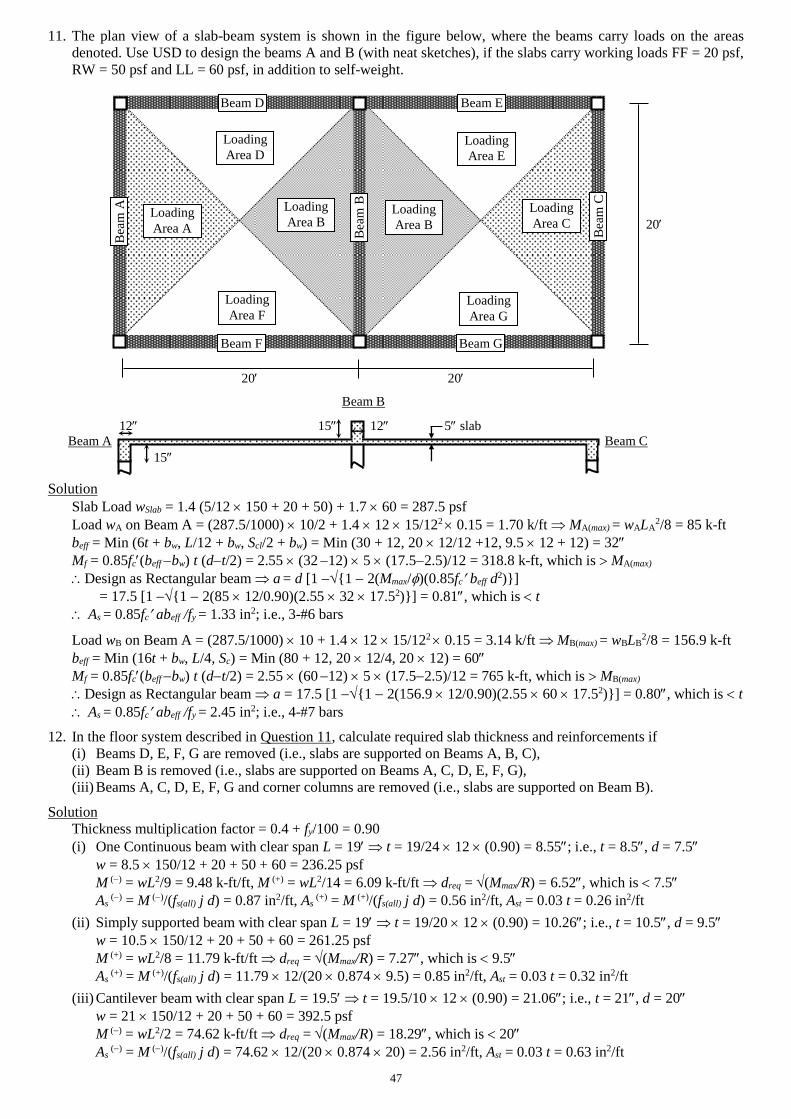
47
11. The plan view of a slab-beam system is shown in the figure below, where the beams carry loads on the areas
denoted. Use USD to design the beams A and B (with neat sketches), if the slabs carry working loads FF = 20 psf,
RW = 50 psf and LL = 60 psf, in addition to self-weight.
20
20 20
Beam B
12 15 12 5 slab
Beam A Beam C
15
Solution
Slab Load wSlab = 1.4 (5/12 150 + 20 + 50) + 1.7 60 = 287.5 psf
Load wA on Beam A = (287.5/1000) 10/2 + 1.4 12 15/122 0.15 = 1.70 k/ft MA(max) = wALA2/8 = 85 k-ft
beff = Min (6t + bw, L/12 + bw, Scl/2 + bw) = Min (30 + 12, 20 12/12 +12, 9.5 12 + 12) = 32
Mf = 0.85fc(beff bw) t (dt/2) = 2.55 (32 12) 5 (17.52.5)/12 = 318.8 k-ft, which is MA(max)
Design as Rectangular beam a = d [1 {1 2(Mmax/)(0.85fc beff d2)}]
= 17.5 [1 {1 2(85 12/0.90)(2.55 32 17.52)}] = 0.81, which is t
As = 0.85fc abeff /fy = 1.33 in2; i.e., 3-#6 bars
Load wB on Beam A = (287.5/1000) 10 + 1.4 12 15/122 0.15 = 3.14 k/ft MB(max) = wBLB2/8 = 156.9 k-ft
beff = Min (16t + bw, L/4, Sc) = Min (80 + 12, 20 12/4, 20 12) = 60
Mf = 0.85fc(beff bw) t (dt/2) = 2.55 (60 12) 5 (17.52.5)/12 = 765 k-ft, which is MB(max)
Design as Rectangular beam a = 17.5 [1 {1 2(156.9 12/0.90)(2.55 60 17.52)}] = 0.80, which is t
As = 0.85fc abeff /fy = 2.45 in2; i.e., 4-#7 bars
12. In the floor system described in Question 11, calculate required slab thickness and reinforcements if
(i) Beams D, E, F, G are removed (i.e., slabs are supported on Beams A, B, C),
(ii) Beam B is removed (i.e., slabs are supported on Beams A, C, D, E, F, G),
(iii) Beams A, C, D, E, F, G and corner columns are removed (i.e., slabs are supported on Beam B).
Solution
Thickness multiplication factor = 0.4 + fy/100 = 0.90
(i) One Continuous beam with clear span L = 19 t = 19/24 12 (0.90) = 8.55; i.e., t = 8.5, d = 7.5
w = 8.5 150/12 + 20 + 50 + 60 = 236.25 psf
M () = wL2/9 = 9.48 k-ft/ft, M (+) = wL2/14 = 6.09 k-ft/ft dreq = (Mmax/R) = 6.52, which is 7.5
As () = M ()/(fs(all) j d) = 0.87 in2/ft, As
(+) = M (+)/(fs(all) j d) = 0.56 in2/ft, Ast = 0.03 t = 0.26 in2/ft
(ii) Simply supported beam with clear span L = 19 t = 19/20 12 (0.90) = 10.26; i.e., t = 10.5, d = 9.5
w = 10.5 150/12 + 20 + 50 + 60 = 261.25 psf
M (+) = wL2/8 = 11.79 k-ft/ft dreq = (Mmax/R) = 7.27, which is 9.5
As (+) = M (+)/(fs(all) j d) = 11.79 12/(20 0.874 9.5) = 0.85 in2/ft, Ast = 0.03 t = 0.32 in2/ft
(iii) Cantilever beam with clear span L = 19.5 t = 19.5/10 12 (0.90) = 21.06; i.e., t = 21, d = 20
w = 21 150/12 + 20 + 50 + 60 = 392.5 psf
M () = wL2/2 = 74.62 k-ft/ft dreq = (Mmax/R) = 18.29, which is 20
As () = M ()/(fs(all) j d) = 74.62 12/(20 0.874 20) = 2.56 in2/ft, Ast = 0.03 t = 0.63 in2/ft
Bea
m A
Loading
Area A
Loading
Area B Loading
Area C
Bea
m B
Bea
m C
Beam D Beam E
Beam F Beam G
Loading
Area B
Loading
Area D Loading
Area E
Loading
Area F Loading
Area G
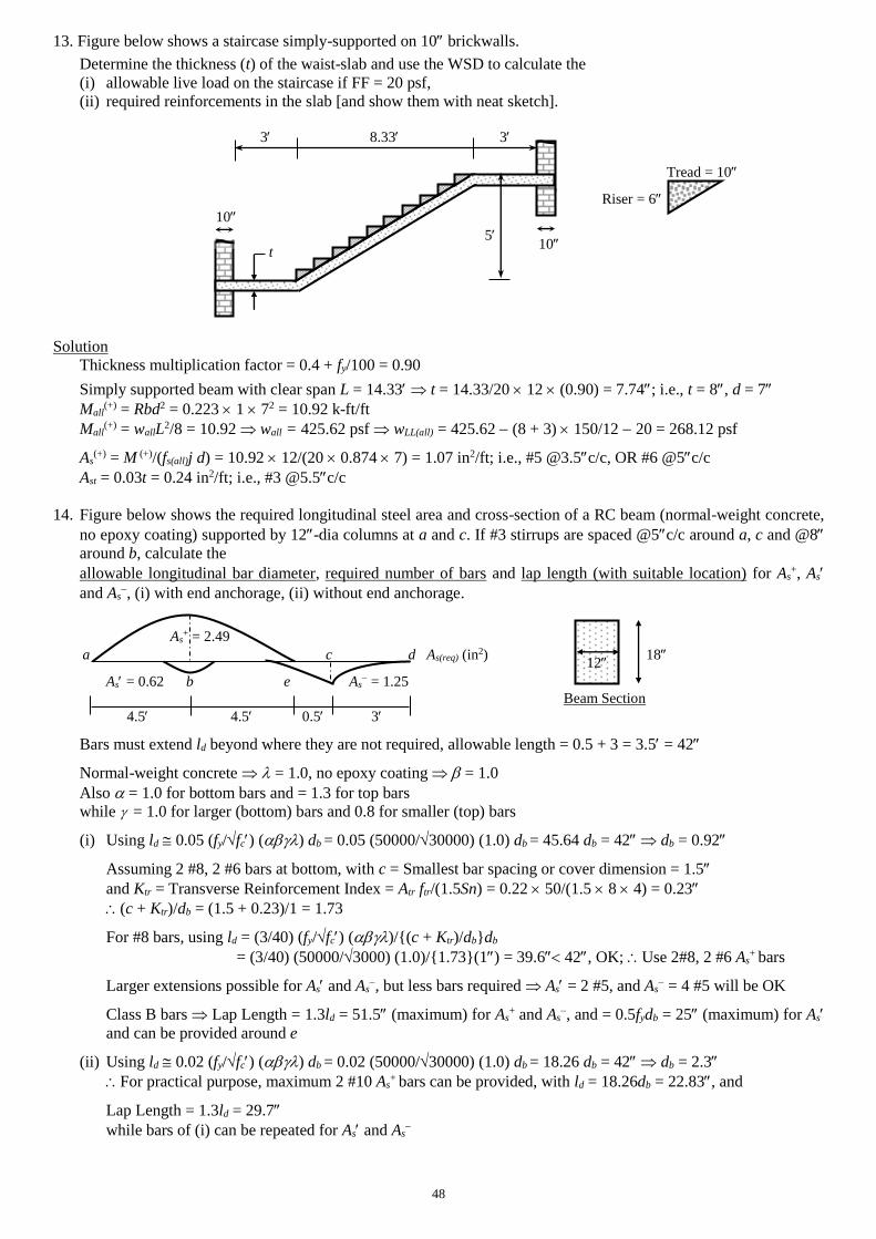
48
13. Figure below shows a staircase simply-supported on 10 brickwalls.
Determine the thickness (t) of the waist-slab and use the WSD to calculate the
(i) allowable live load on the staircase if FF = 20 psf,
(ii) required reinforcements in the slab [and show them with neat sketch].
3 8.33 3
Tread = 10
Riser = 6
10
5
t
Solution
Thickness multiplication factor = 0.4 + fy/100 = 0.90
Simply supported beam with clear span L = 14.33 t = 14.33/20 12 (0.90) = 7.74; i.e., t = 8, d = 7
Mall(+) = Rbd2 = 0.223 1 72 = 10.92 k-ft/ft
Mall(+) = wallL2/8 = 10.92 wall = 425.62 psf wLL(all) = 425.62 (8 + 3) 150/12 20 = 268.12 psf
As(+) = M (+)/(fs(all)j d) = 10.92 12/(20 0.874 7) = 1.07 in2/ft; i.e., #5 @3.5c/c, OR #6 @5c/c
Ast = 0.03t = 0.24 in2/ft; i.e., #3 @5.5c/c
14. Figure below shows the required longitudinal steel area and cross-section of a RC beam (normal-weight concrete,
no epoxy coating) supported by 12-dia columns at a and c. If #3 stirrups are spaced @5c/c around a, c and @8
around b, calculate the
allowable longitudinal bar diameter, required number of bars and lap length (with suitable location) for As+, As
and As, (i) with end anchorage, (ii) without end anchorage.
As+ = 2.49
a c d As(req) (in2) 18
As = 0.62 b e As = 1.25
Beam Section
4.5 4.5 0.5 3
Bars must extend ld beyond where they are not required, allowable length = 0.5 + 3 = 3.5 = 42
Normal-weight concrete = 1.0, no epoxy coating = 1.0
Also = 1.0 for bottom bars and = 1.3 for top bars
while = 1.0 for larger (bottom) bars and 0.8 for smaller (top) bars
(i) Using ld 0.05 (fy/fc) () db = 0.05 (50000/30000) (1.0) db = 45.64 db = 42 db = 0.92
Assuming 2 #8, 2 #6 bars at bottom, with c = Smallest bar spacing or cover dimension = 1.5
and Ktr = Transverse Reinforcement Index = Atr ftr/(1.5Sn) = 0.22 50/(1.5 8 4) = 0.23
(c + Ktr)/db = (1.5 + 0.23)/1 = 1.73
For #8 bars, using ld = (3/40) (fy/fc) ()/{(c + Ktr)/db}db
= (3/40) (50000/3000) (1.0)/{1.73}(1) = 39.6 42, OK; Use 2#8, 2 #6 As+ bars
Larger extensions possible for As and As, but less bars required As = 2 #5, and As
= 4 #5 will be OK
Class B bars Lap Length = 1.3ld = 51.5 (maximum) for As+ and As
, and = 0.5fydb = 25 (maximum) for As
and can be provided around e
(ii) Using ld 0.02 (fy/fc) () db = 0.02 (50000/30000) (1.0) db = 18.26 db = 42 db = 2.3
For practical purpose, maximum 2 #10 As+ bars can be provided, with ld = 18.26db = 22.83, and
Lap Length = 1.3ld = 29.7
while bars of (i) can be repeated for As and As
10
12