Embed Size (px)
Citation preview
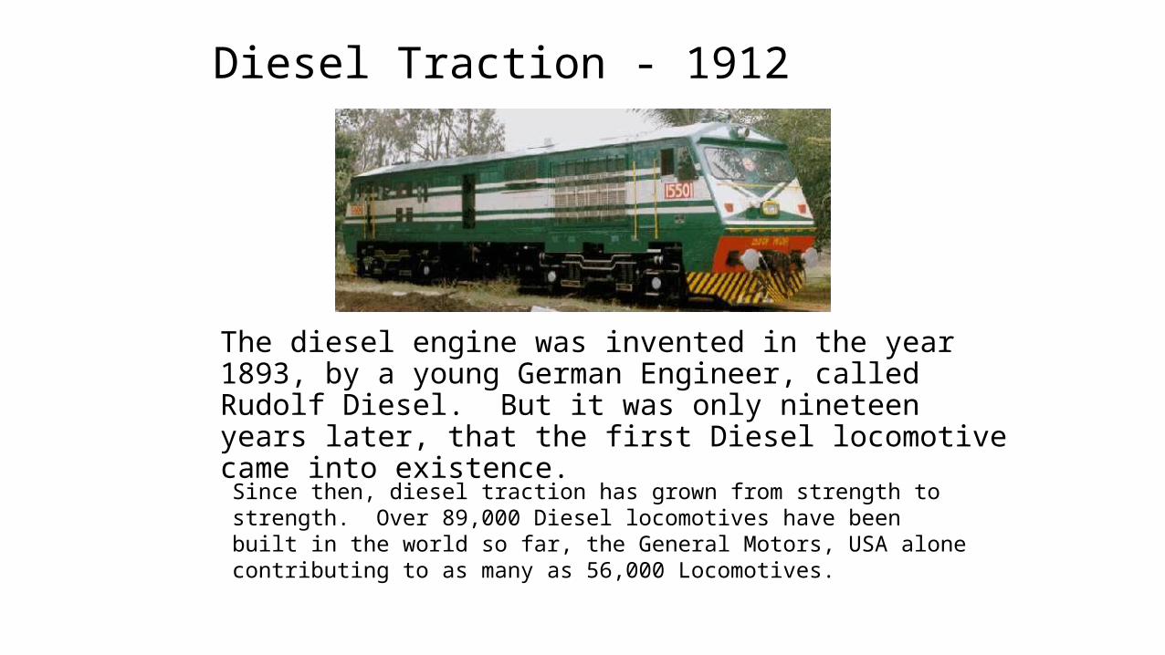
Diesel Traction - 1912
The diesel engine was invented in the year 1893, by a young German Engineer, called Rudolf Diesel. But it was only nineteen years later, that the first Diesel locomotive came into existence. Since then, diesel traction has grown from strength to strength. Over 89,000 Diesel locomotives have been built in the world so far, the General Motors, USA alone contributing to as many as 56,000 Locomotives.
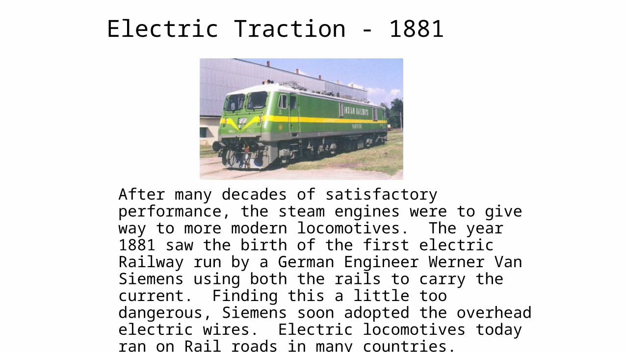
Electric Traction - 1881
After many decades of satisfactory performance, the steam engines were to give way to more modern locomotives. The year 1881 saw the birth of the first electric Railway run by a German Engineer Werner Van Siemens using both the rails to carry the current. Finding this a little too dangerous, Siemens soon adopted the overhead electric wires. Electric locomotives today ran on Rail roads in many countries.
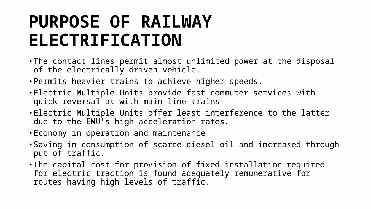
PURPOSE OF RAILWAY ELECTRIFICATION• The contact lines permit almost unlimited power at the disposal of the electrically
driven vehicle.• Permits heavier trains to achieve higher speeds.• Electric Multiple Units provide fast commuter services with quick reversal at with
main line trains• Electric Multiple Units offer least interference to the latter due to the EMU’s high
acceleration rates.• Economy in operation and maintenance• Saving in consumption of scarce diesel oil and increased through put of traffic. • The capital cost for provision of fixed installation required for electric traction is
found adequately remunerative for routes having high levels of traffic.
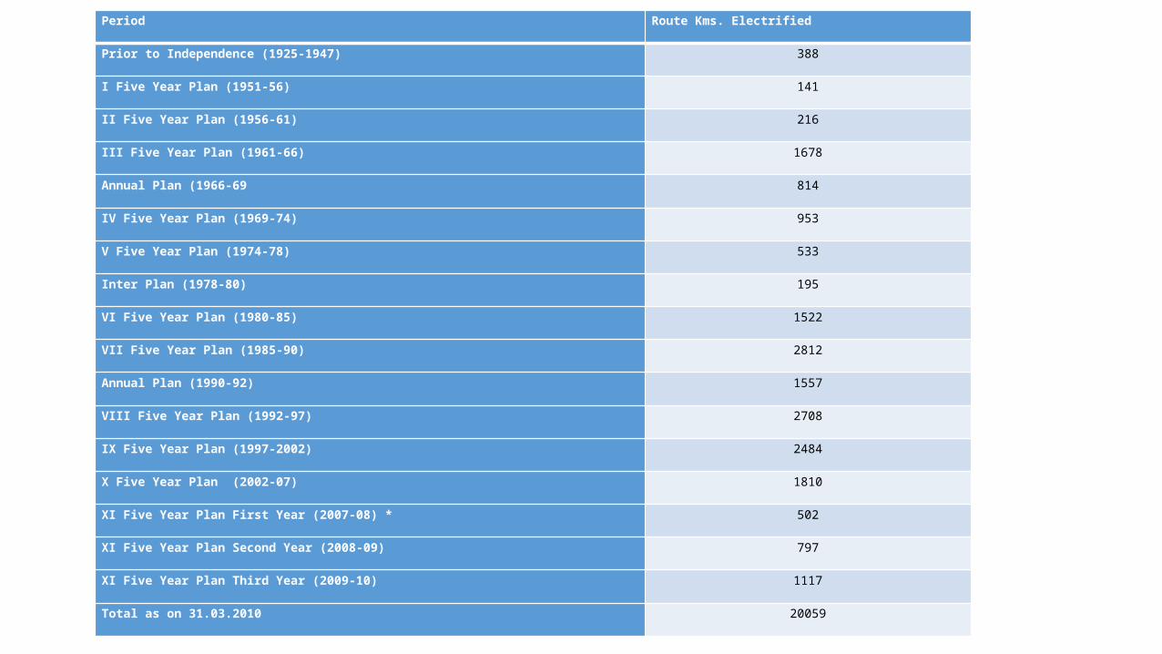
Period Route Kms. Electrified
Prior to Independence (1925-1947) 388
I Five Year Plan (1951-56) 141
II Five Year Plan (1956-61) 216
III Five Year Plan (1961-66) 1678
Annual Plan (1966-69 814
IV Five Year Plan (1969-74) 953
V Five Year Plan (1974-78) 533
Inter Plan (1978-80) 195
VI Five Year Plan (1980-85) 1522
VII Five Year Plan (1985-90) 2812
Annual Plan (1990-92) 1557
VIII Five Year Plan (1992-97) 2708
IX Five Year Plan (1997-2002) 2484
X Five Year Plan (2002-07) 1810
XI Five Year Plan First Year (2007-08) * 502
XI Five Year Plan Second Year (2008-09) 797
XI Five Year Plan Third Year (2009-10) 1117
Total as on 31.03.2010 20059
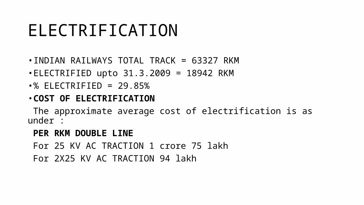
ELECTRIFICATION• INDIAN RAILWAYS TOTAL TRACK = 63327 RKM• ELECTRIFIED upto 31.3.2009 = 18942 RKM• % ELECTRIFIED = 29.85%• COST OF ELECTRIFICATION The approximate average cost of electrification is as under : PER RKM DOUBLE LINE For 25 KV AC TRACTION 1 crore 75 lakh For 2X25 KV AC TRACTION 94 lakh
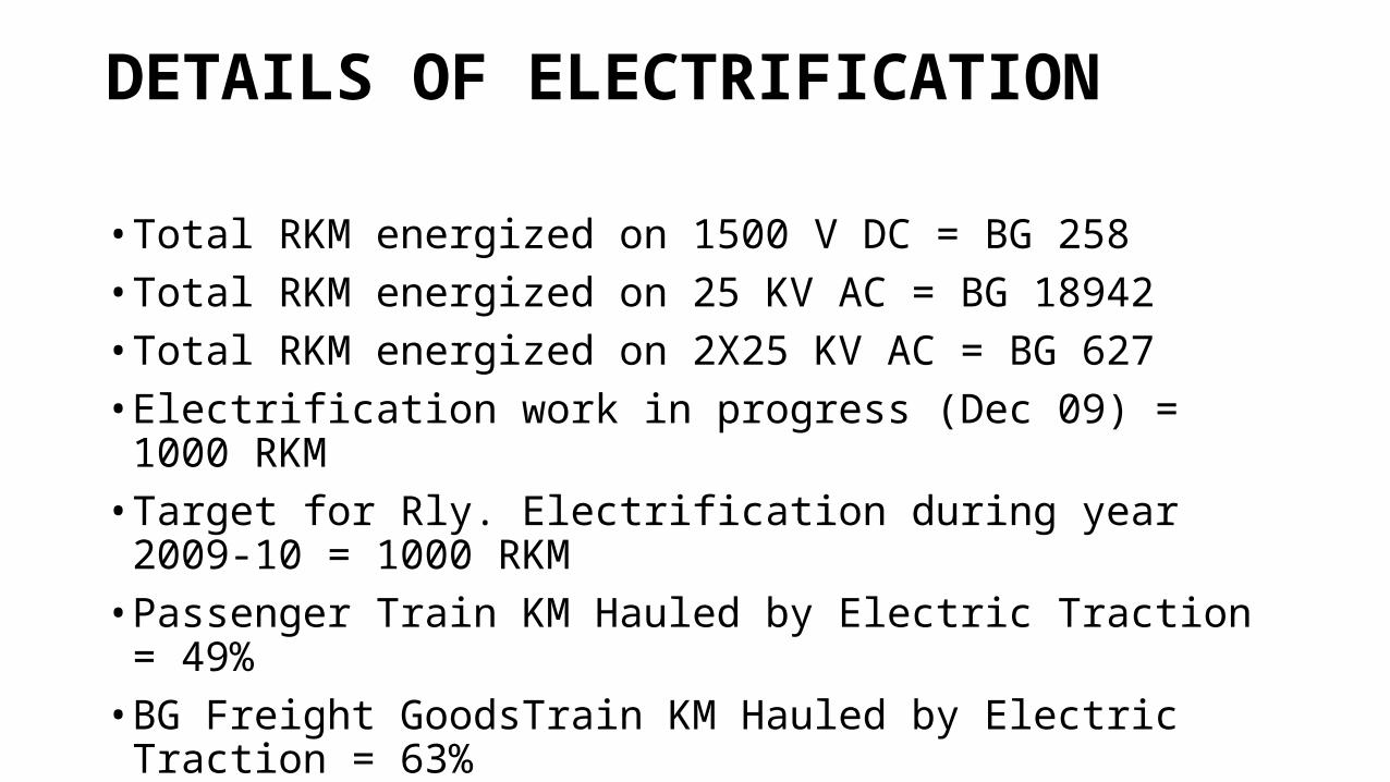
DETAILS OF ELECTRIFICATION
• Total RKM energized on 1500 V DC = BG 258• Total RKM energized on 25 KV AC = BG 18942• Total RKM energized on 2X25 KV AC = BG 627• Electrification work in progress (Dec 09) = 1000 RKM• Target for Rly. Electrification during year 2009-10 = 1000 RKM• Passenger Train KM Hauled by Electric Traction = 49%• BG Freight GoodsTrain KM Hauled by Electric Traction = 63%
ONGOING PROJECT • Notification of Award No & DateIFB No, RVNL/CPM/MAS/VLDE-MPA-DG/OT-4 dated 24/01/2012
• Description of Item/WorkExecution of Doubling of track between Villupuram and Dindigul, for the contract Package-1-“Construction of Roadbed, bridges, supply of ballast, Installation of track (excluding supply of rails & PSC sleepers), Electrical (Railway Electrification and General Electrification), outdoor signalling and telecommunication works for Doubling of track between Valadi and Manaparai in Tiruchchirappalli and Madurai Divisions of Southern Railway, TamilNadu, India.”
-58km stretch-
• Contract No & DateLOANo.RVNL/CPMMAS/VLDE-MPA-DG/OT-4/Package 1 dated 22.10.2012
• Contractor's NameM/s L&T Construction Infrastructure Mount Poonamallee RoadPB No. 979Chennai - 600 089
• Total Tender Cost (for Engg./Elect./S&T) Rs.157,53,91,274
Double track
• A double-track railway usually involves running one track in each direction, compared to a single-track railway where trains in both directions share the same track.• Double-track railways, especially older ones, may use each track
exclusively in one direction. This arrangement simplifies the signalling systems, especially where the signalling is mechanical.• Where the signals and points or rail switches are power-operated, it can
be worthwhile to signal each line in both directions, so that the double line becomes a pair of single lines. This allows trains to use one track where the other track is out of service due to track maintenance work, or a train failure, or for a fast train to overtake a slow train.
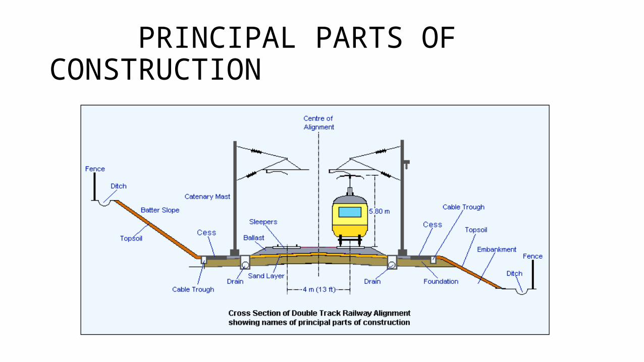
PRINCIPAL PARTS OF CONSTRUCTION
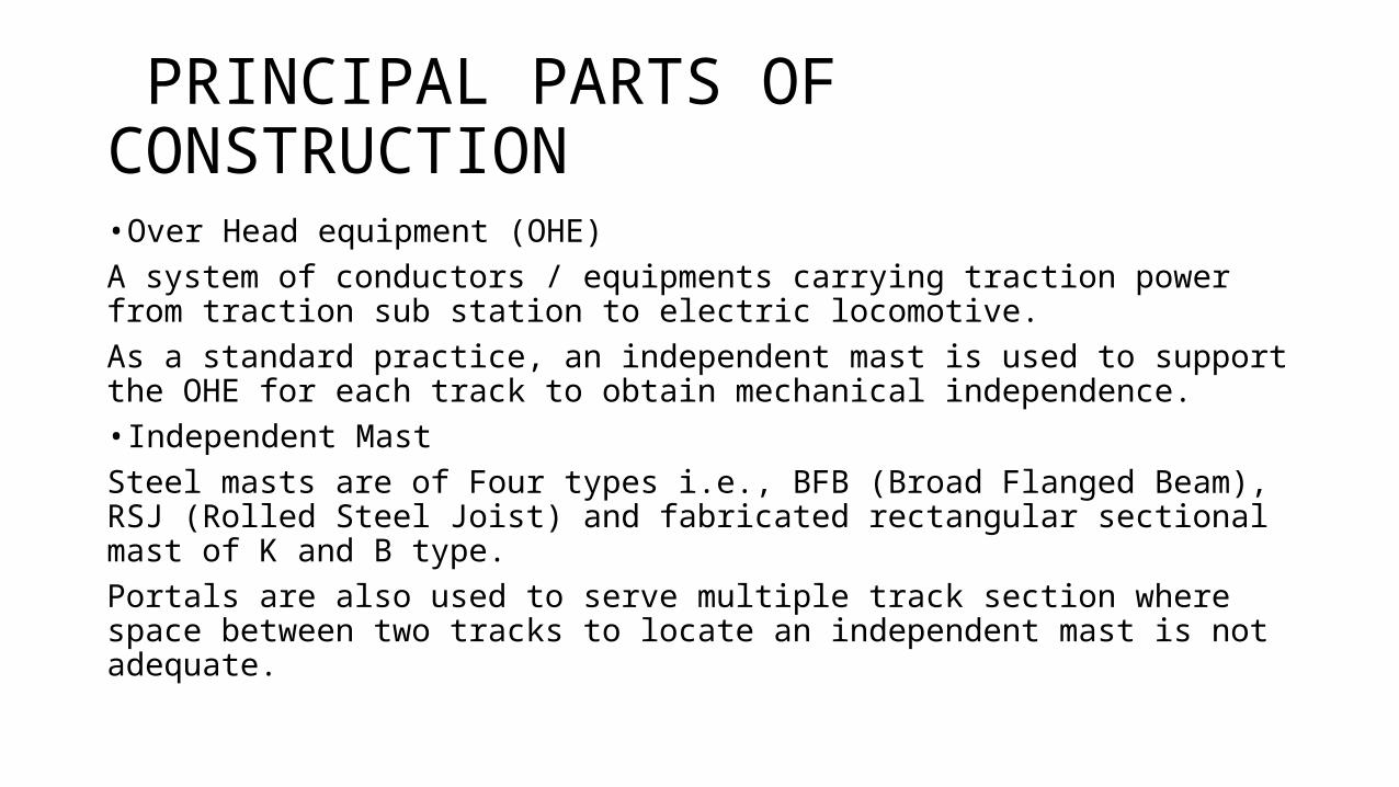
PRINCIPAL PARTS OF CONSTRUCTION• Over Head equipment (OHE)A system of conductors / equipments carrying traction power from traction sub station to electric locomotive.As a standard practice, an independent mast is used to support the OHE for each track to obtain mechanical independence. • Independent MastSteel masts are of Four types i.e., BFB (Broad Flanged Beam), RSJ (Rolled Steel Joist) and fabricated rectangular sectional mast of K and B type.Portals are also used to serve multiple track section where space between two tracks to locate an independent mast is not adequate.
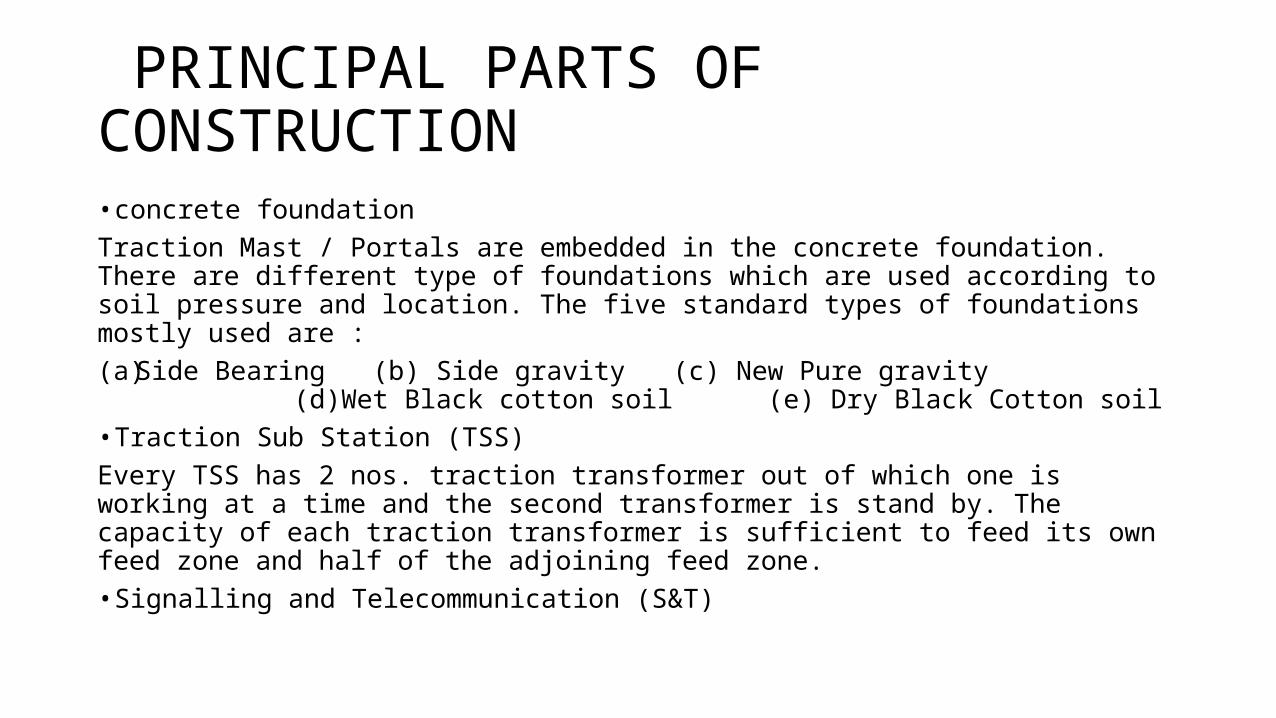
PRINCIPAL PARTS OF CONSTRUCTION• concrete foundationTraction Mast / Portals are embedded in the concrete foundation. There are different type of foundations which are used according to soil pressure and location. The five standard types of foundations mostly used are :(a) Side Bearing (b) Side gravity (c) New Pure gravity (d)Wet Black
cotton soil (e) Dry Black Cotton soil• Traction Sub Station (TSS)Every TSS has 2 nos. traction transformer out of which one is working at a time and the second transformer is stand by. The capacity of each traction transformer is sufficient to feed its own feed zone and half of the adjoining feed zone.• Signalling and Telecommunication (S&T)
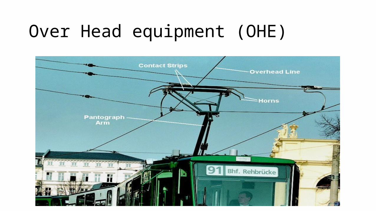
Over Head equipment (OHE)
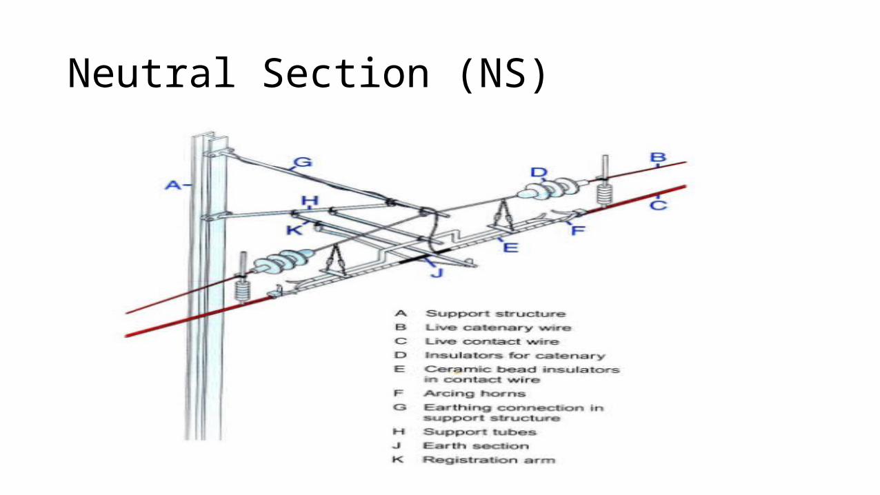
Neutral Section (NS)
RAILWAY ELECTRIFICATION WORKS• Main works1 Provision of most economic reliable electric contact system to continuously supply power to the moving electric rolling stock.2. Power Supply Arrangements.3. Provision of switches to regulate the flow of power along with the electric protective gear.4. Monitoring and remote control of power supply.5. Immunization of signalling and the trackside telecommunication circuits against electromagnetic and electrostatic induction effects of 25 KV, 50 HZ, single phase traction power supply.6. Modernization of signalling and telecommunication.7. Provision of maintenance and operation facilities for electric traction.
RAILWAY ELECTRIFICATION WORKS• Discipline wise Division of Worksa) Electricalb) Signal and Telecommunicationsc) Civil Engineering
Coordination of Works
• Railway Electrification, being a multi-disciplinary project work, needs close coordination amongst electrical, signalling & telecommunications and civil engineering disciplines. It further needs coordination with outside agencies such as Power Supply Authorities, the Department of Telecommunications, the Revenue officials as well as with the Open Line organization or whose section the work is to be taken up. Accordingly the organization for Railway electrification coordinates works of all the disciplines and the agencies from inception to completion including support services to the open line in early stages of electric traction over the section.
19
20
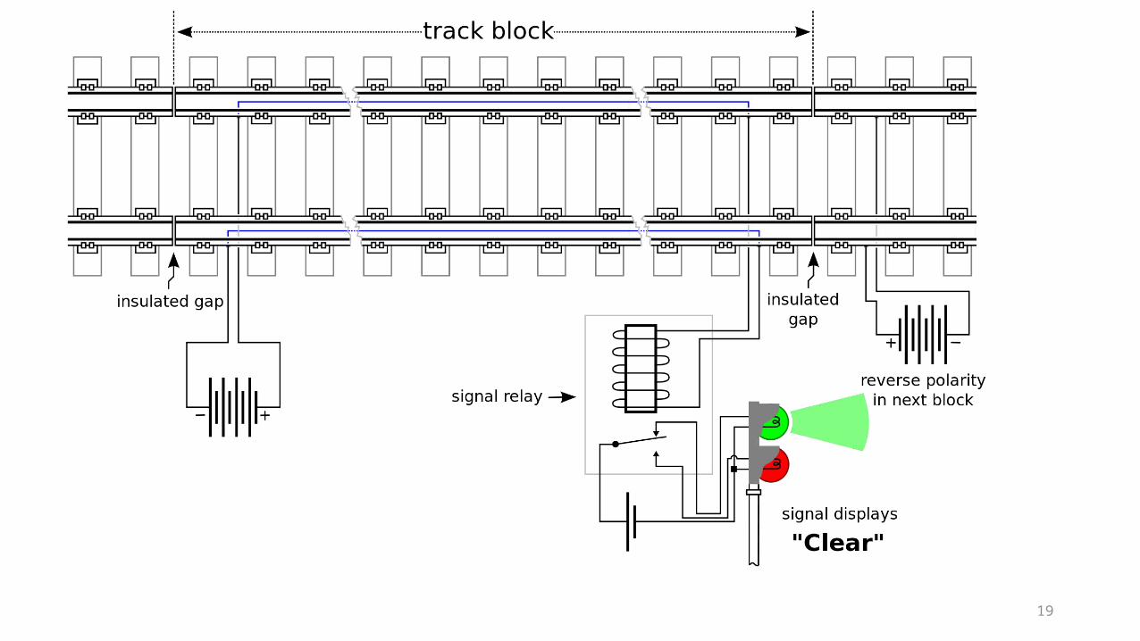
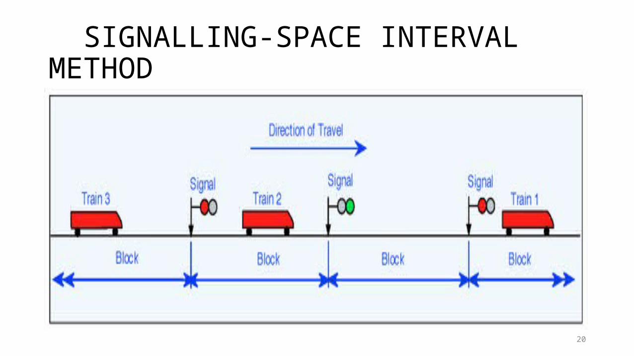
SIGNALLING-SPACE INTERVAL METHOD
21
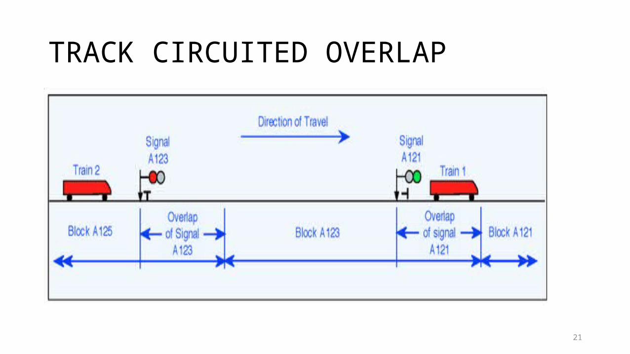
TRACK CIRCUITED OVERLAP
22
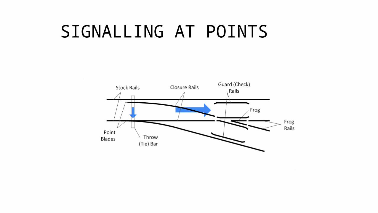
SIGNALLING AT POINTS
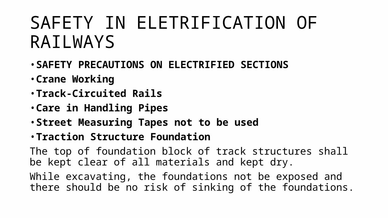
SAFETY IN ELETRIFICATION OF RAILWAYS• SAFETY PRECAUTIONS ON ELECTRIFIED SECTIONS• Crane Working• Track-Circuited Rails• Care in Handling Pipes• Street Measuring Tapes not to be used• Traction Structure FoundationThe top of foundation block of track structures shall be kept clear of all materials and kept dry.While excavating, the foundations not be exposed and there should be no risk of sinking of the foundations.
COST ESTIMATION • At the planning level strategic decisions are developed that determine
the likely benefits and costs of a project, before further resources are utilized for more in-depth investigation. At the project level actual location specific studies are conducted to determine the overall costs of the project.
• CPM estimation methodology is used at the planning level
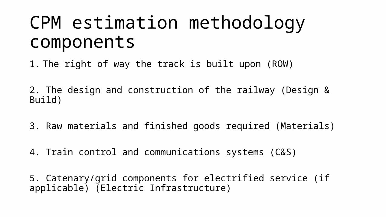
CPM estimation methodology components1. The right of way the track is built upon (ROW)
2. The design and construction of the railway (Design & Build)
3. Raw materials and finished goods required (Materials)
4. Train control and communications systems (C&S)
5. Catenary/grid components for electrified service (if applicable) (Electric Infrastructure)
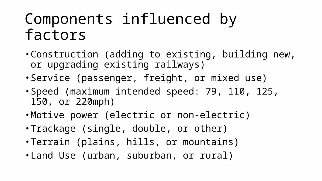
Components influenced by factors• Construction (adding to existing, building new, or upgrading existing
railways)• Service (passenger, freight, or mixed use)• Speed (maximum intended speed: 79, 110, 125, 150, or 220mph)• Motive power (electric or non-electric)• Trackage (single, double, or other)• Terrain (plains, hills, or mountains)• Land Use (urban, suburban, or rural)
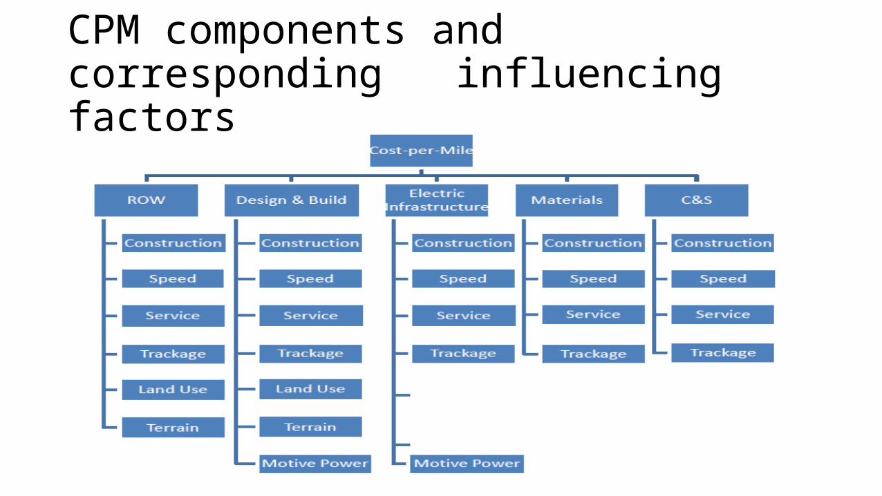
CPM components and corresponding influencing factors
CPM ADJUSTMENT FACTORS• The five CPM component cost categories have been designated as
“Design & Build”, “ROW”, “Materials”, “C&S”, and “Electric Infrastructure”. Each cost is based on a finished project, proposed project, or study cost. Since most of the cost sources pertained to a particular project.• To achieve this, the US Army Corps of Engineers “Civil Works
Construction Cost Index System (CWCCIS)” was applied. The index is used to “…escalate or inflate various project cost features to current or future price levels…” along with adjusting for the influence of a project on construction costs.
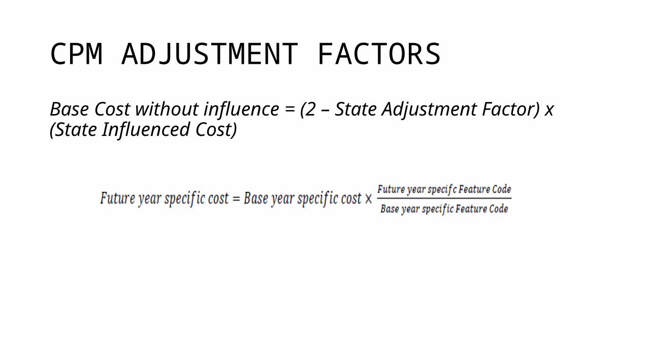
CPM ADJUSTMENT FACTORSBase Cost without influence = (2 – State Adjustment Factor) x (State Influenced Cost)
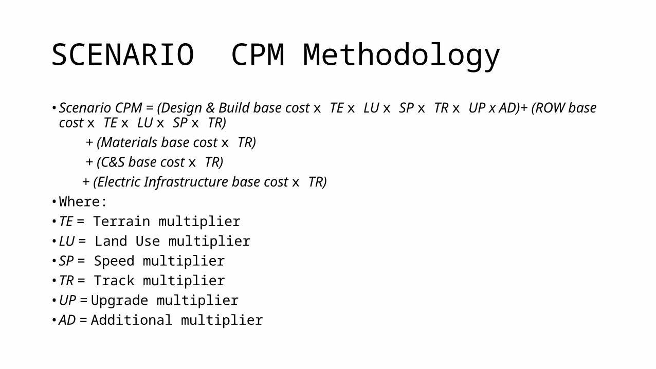
SCENARIO CPM Methodology• Scenario CPM = (Design & Build base cost x TE x LU x SP x TR x UP x AD)+ (ROW base cost x TE x LU
x SP x TR) + (Materials base cost x TR) + (C&S base cost x TR) + (Electric Infrastructure base cost x TR)• Where:• TE = Terrain multiplier• LU = Land Use multiplier• SP = Speed multiplier• TR = Track multiplier• UP = Upgrade multiplier• AD = Additional multiplier
References Indian Railway Year Book 2002-2003U.S. Army Corps of Engineers, 2000Transportation Research Board, 2000• White, Thomas. 2000. Developing The Pacific Northwest Rail Corridor Incremental Plan. [Online]• 2000. [Cited: September 29, 2011.]• http://www.halcyon.com/tawhite/Trans/PNWRC%20INCREMENTAL%20PLAN.htm.• Whitford, R. K. 1981. Railroad Electrification. An Alternative for Petroleum Savings. Transportation• Research Record. 1981, 802.• a planning methodology for railway construction• cost estimation in north america• Jeffrey Tyler Von Brown