Embed Size (px)
Citation preview
1
Koya University Faculty of Engineering
Chemical Engineering Department
Laboratory of Heat transfer Experiment Number Two Radial heat conduction
Instructor: Dr.Barham & Mrs.Anfal
Name of Student: Aree Salah Tahir
Experiment Contacted on: 12/ Nov/2014
Report Submitted on: 24/Nov/2014
Group:A
2
List of content:
Objectives……………............................................3
Introduction..………………………………… ….4
Background Theory ...……..…………...…..…….5
Procedure ………………..…………..……...……6
Equipment and components used………………...7
Table of Reading……………….…………......….8
Calculation…………...............................9-10-11-12
Discussion …..………………………….…...13-14
References ……………………...…………..…16
3
Objectives:
It allows us to obtain experimentally the coefficient of thermal
conductivity of some unknown materials ,and in this way to
understand the factors and parameters that affect the rate of heat
transfer.
4
Introduction:
Heat transfer is a common phenomenon encountered in many areas in daily life. It
is an important subject in natural sciences and even more so in engineering and the
field of environmental physics. Knowledge about heat transfer is essential for the
various possible ways to cut down on energy use. For example, to economize on
home-heating one has to optimize insulation, i.e. minimize heat transfer. Improving
cooling processes on the other hand implies maximizing heat transfer to the coolant.
Engineering problems that involve heat transfer are generally concerned with
optimization of heat transfer processes. For instance, in the development of novel
materials that cannot sustain extreme temperatures heat transport towards the
material is to be minimized, whereas the transport away from this material is to be
maximized. Research on heat transfer focusses on electronic equipment, energy
systems, fire and combustion systems, gas turbines, as well as manufacturing and
materials processing. There is even a Journal of Heat Transfer whose emphasis is
on energy transfer in applied thermodynamic processes in all fields of (mechanical)
engineering and related industries. Therefore it is important to understand the basic
concepts of heat transfer and the way it is mathematically described. You should be
already familiar with the different mechanisms that result in heat transfer from the
lecture. The most important heat transfer mechanisms are:
• Conduction; on a microscopic or atomic scale kinetic energy is transferred
through collisions between the atoms so that on a macroscopic scale thermal
energy is transferred.
• Convection; if the carrier of thermal energy is mobile, the thermal energy may
be transferred through mass transfer.
• Radiation; thermal energy may be transformed into electromagnetic energy,
emitted, absorbed and with that it is transformed into thermal energy again
{1}
5
Background Theory:
Conduction: is the molecular transfer of heat in solid, liquid, and gaseous media
under the influence of a temperature difference.
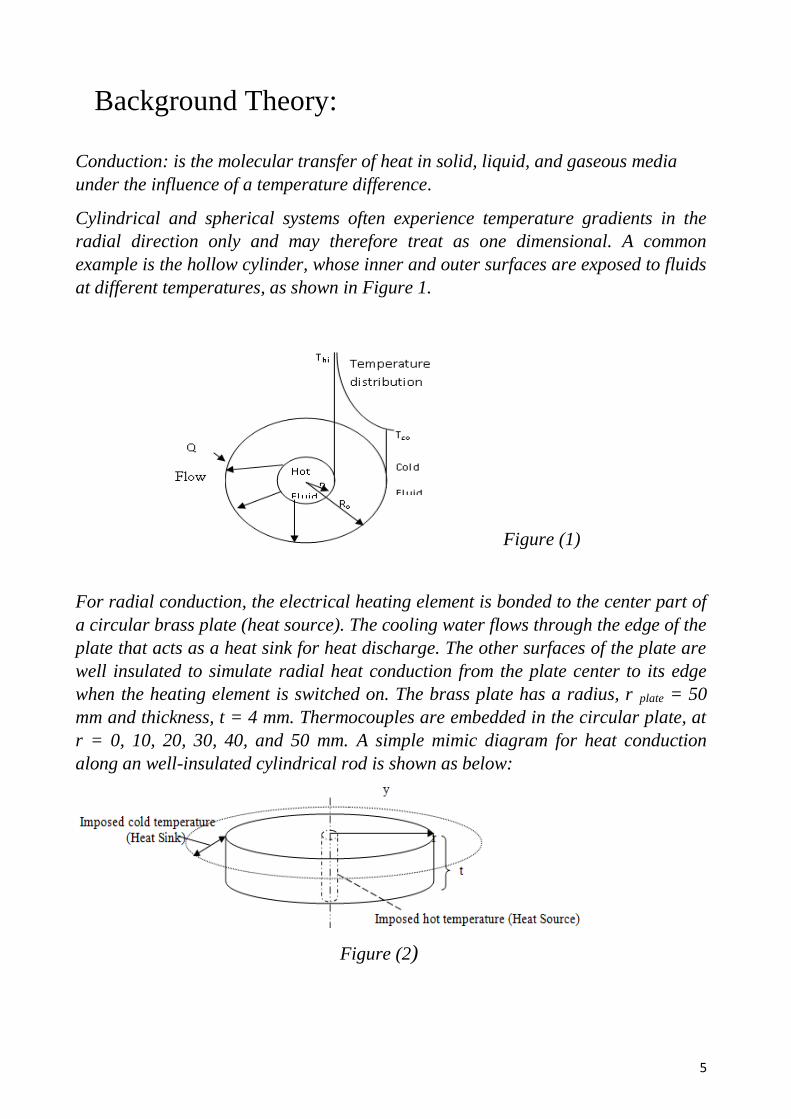
Cylindrical and spherical systems often experience temperature gradients in the
radial direction only and may therefore treat as one dimensional. A common
example is the hollow cylinder, whose inner and outer surfaces are exposed to fluids
at different temperatures, as shown in Figure 1.
Figure (1)
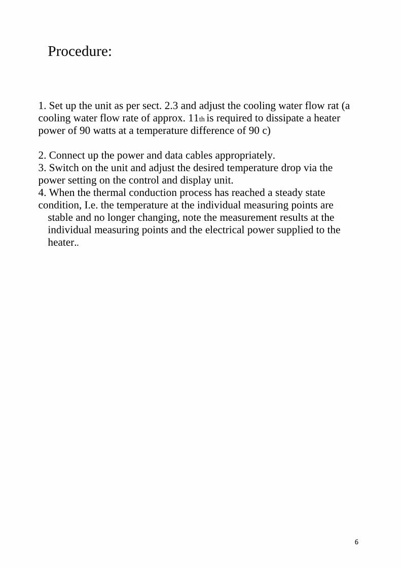
For radial conduction, the electrical heating element is bonded to the center part of
a circular brass plate (heat source). The cooling water flows through the edge of the
plate that acts as a heat sink for heat discharge. The other surfaces of the plate are
well insulated to simulate radial heat conduction from the plate center to its edge
when the heating element is switched on. The brass plate has a radius, r plate = 50
mm and thickness, t = 4 mm. Thermocouples are embedded in the circular plate, at
r = 0, 10, 20, 30, 40, and 50 mm. A simple mimic diagram for heat conduction
along an well-insulated cylindrical rod is shown as below:
Figure (2)
6
Procedure:
1. Set up the unit as per sect. 2.3 and adjust the cooling water flow rat (a
cooling water flow rate of approx. 11th is required to dissipate a heater
power of 90 watts at a temperature difference of 90 c)
2. Connect up the power and data cables appropriately.
3. Switch on the unit and adjust the desired temperature drop via the
power setting on the control and display unit.
4. When the thermal conduction process has reached a steady state
condition, I.e. the temperature at the individual measuring points are
stable and no longer changing, note the measurement results at the
individual measuring points and the electrical power supplied to the
heater..
7
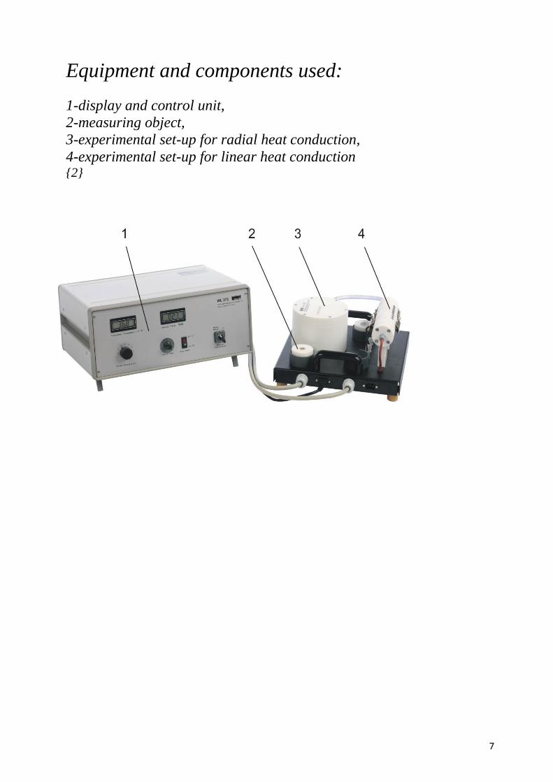
Equipment and components used:
1-display and control unit,
2-measuring object,
3-experimental set-up for radial heat conduction,
4-experimental set-up for linear heat conduction {2}
8
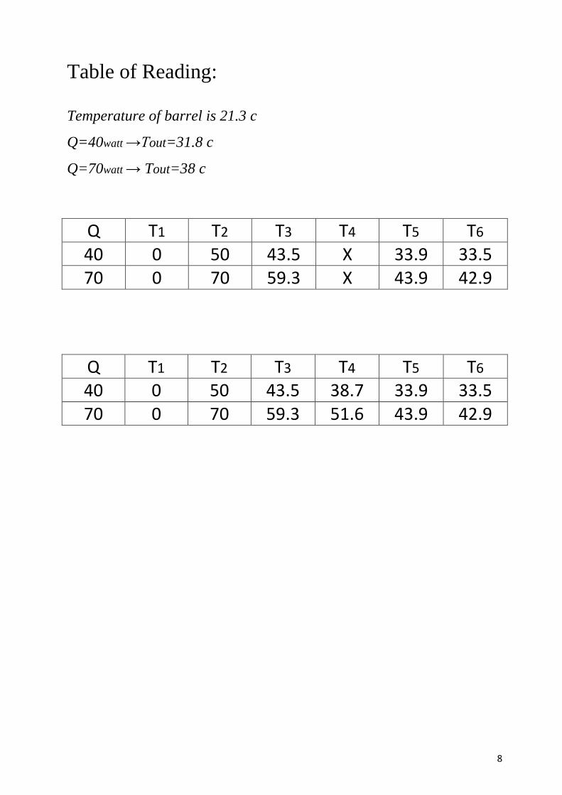
Table of Reading:
Temperature of barrel is 21.3 c
Q=40watt →Tout=31.8 c
Q=70watt → Tout=38 c
Q T1 T2 T3 T4 T5 T6 40 0 50 43.5 X 33.9 33.5 70 0 70 59.3 X 43.9 42.9
Q T1 T2 T3 T4 T5 T6 40 0 50 43.5 38.7 33.9 33.5 70 0 70 59.3 51.6 43.9 42.9
9
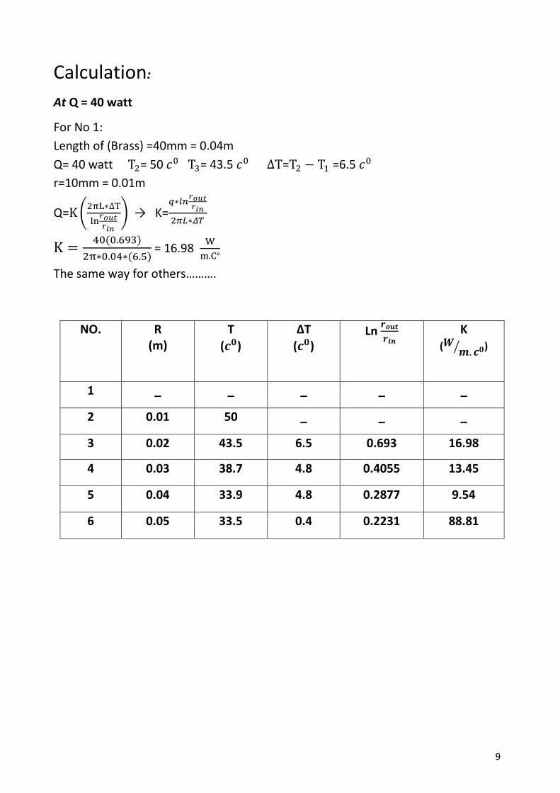
Calculation:
At Q = 40 watt
For No 1:
Length of (Brass) =40mm = 0.04m
Q= 40 watt T2= 50 𝑐0 T3= 43.5 𝑐0 ∆T=T2 − T1 =6.5 𝑐0
r=10mm = 0.01m
Q=K(2πL∗∆T
ln𝑟𝑜𝑢𝑡𝑟𝑖𝑛
) → K=𝑞∗𝑙𝑛
𝑟𝑜𝑢𝑡𝑟𝑖𝑛
2𝜋𝐿∗𝛥𝑇
K =40(0.693)
2π∗0.04∗(6.5) = 16.98
W
m.C°
The same way for others……….
NO. R (m)
T
(𝒄𝟎)
ΔT
(𝒄𝟎) Ln
𝒓𝒐𝒖𝒕
𝒓𝒊𝒏 K
(𝑾𝒎. 𝒄𝟎⁄ )
1 _ _ _ _ _
2 0.01 50 _ _ _
3 0.02 43.5 6.5 0.693 16.98
4 0.03 38.7 4.8 0.4055 13.45
5 0.04 33.9 4.8 0.2877 9.54
6 0.05 33.5 0.4 0.2231 88.81
10
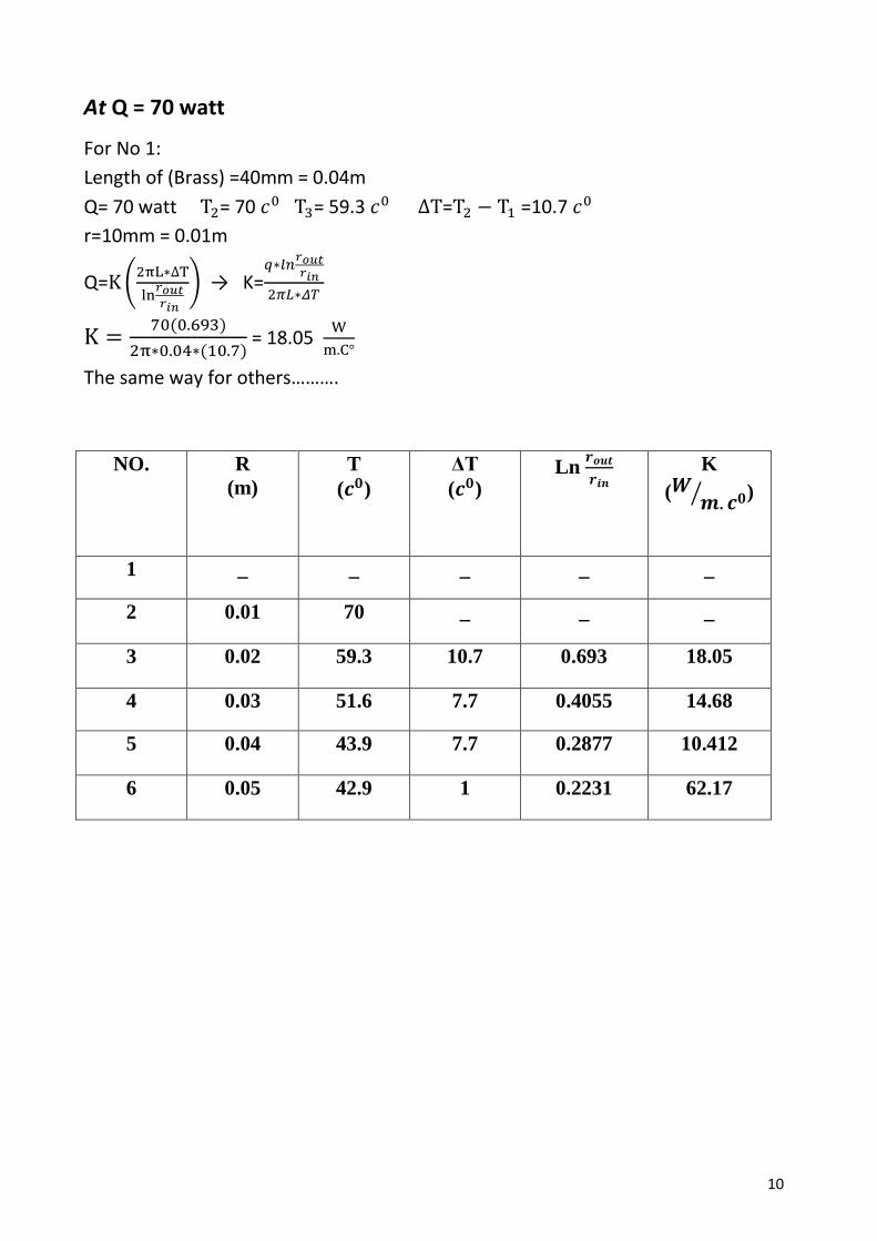
At Q = 70 watt
For No 1:
Length of (Brass) =40mm = 0.04m
Q= 70 watt T2= 70 𝑐0 T3= 59.3 𝑐0 ∆T=T2 − T1 =10.7 𝑐0
r=10mm = 0.01m
Q=K(2πL∗∆T
ln𝑟𝑜𝑢𝑡𝑟𝑖𝑛
) → K=𝑞∗𝑙𝑛
𝑟𝑜𝑢𝑡𝑟𝑖𝑛
2𝜋𝐿∗𝛥𝑇
K =70(0.693)
2π∗0.04∗(10.7) = 18.05
W
m.C°
The same way for others……….
NO. R
(m)
T
(𝒄𝟎)
ΔT
(𝒄𝟎) Ln
𝒓𝒐𝒖𝒕
𝒓𝒊𝒏 K
(𝑾𝒎.𝒄𝟎⁄ )
1 _ _ _ _ _
2 0.01 70 _ _ _
3 0.02 59.3 10.7 0.693 18.05
4 0.03 51.6 7.7 0.4055 14.68
5 0.04 43.9 7.7 0.2877 10.412
6 0.05 42.9 1 0.2231 62.17
11
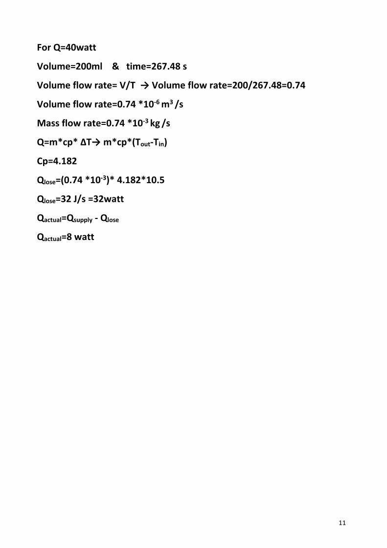
For Q=40watt
Volume=200ml & time=267.48 s
Volume flow rate= V/T → Volume flow rate=200/267.48=0.74
Volume flow rate=0.74 *10-6 m3 /s
Mass flow rate=0.74 *10-3 kg /s
Q=m*cp* ΔT→ m*cp*(Tout-Tin)
Cp=4.182
Qlose=(0.74 *10-3)* 4.182*10.5
Qlose=32 J/s =32watt
Qactual=Qsupply - Qlose
Qactual=8 watt
12
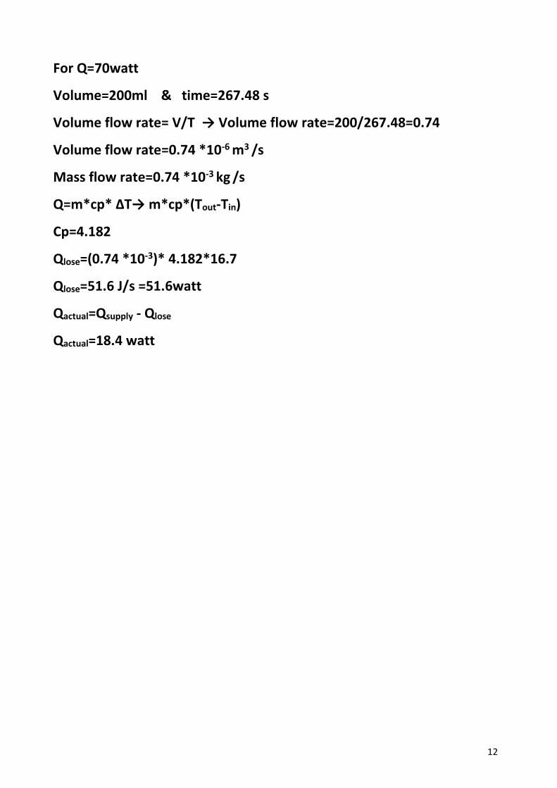
For Q=70watt
Volume=200ml & time=267.48 s
Volume flow rate= V/T → Volume flow rate=200/267.48=0.74
Volume flow rate=0.74 *10-6 m3 /s
Mass flow rate=0.74 *10-3 kg /s
Q=m*cp* ΔT→ m*cp*(Tout-Tin)
Cp=4.182
Qlose=(0.74 *10-3)* 4.182*16.7
Qlose=51.6 J/s =51.6watt
Qactual=Qsupply - Qlose
Qactual=18.4 watt
13
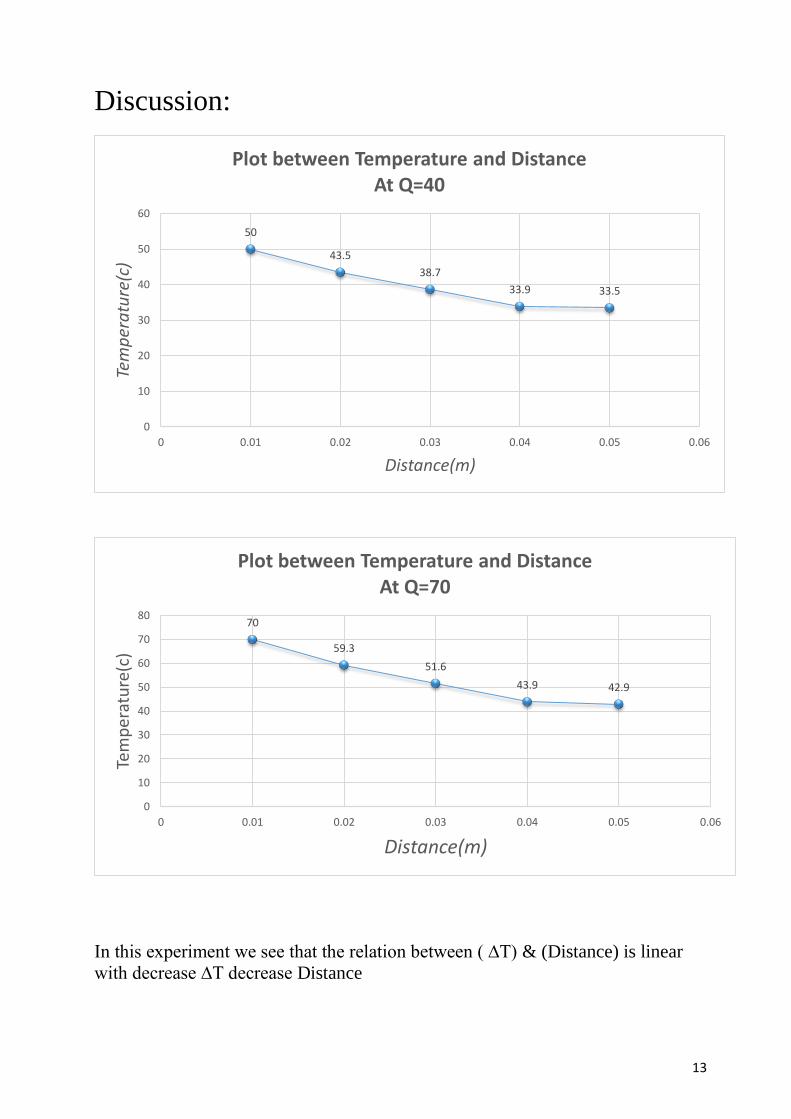
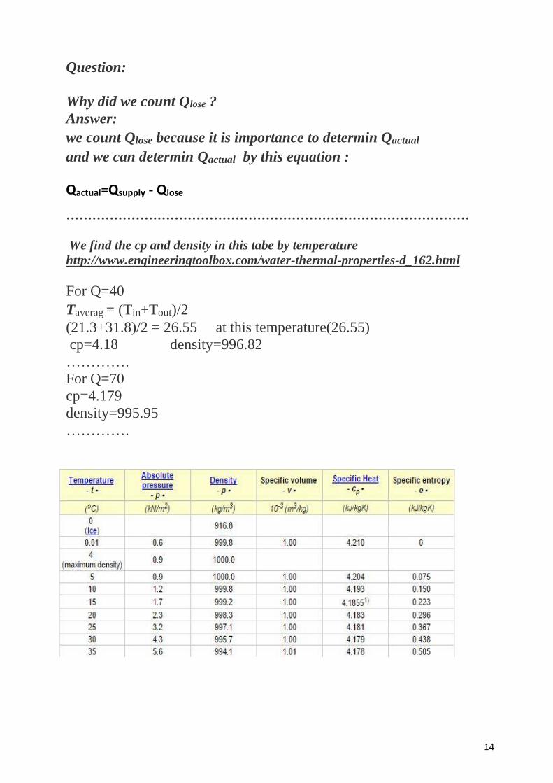
Discussion:
In this experiment we see that the relation between ( ∆T) & (Distance) is linear
with decrease ∆T decrease Distance
50
43.5
38.7
33.9 33.5
0
10
20
30
40
50
60
0 0.01 0.02 0.03 0.04 0.05 0.06
Tem
per
atu
re(c
)
Distance(m)
Plot between Temperature and DistanceAt Q=40
70
59.3
51.6
43.9 42.9
0
10
20
30
40
50
60
70
80
0 0.01 0.02 0.03 0.04 0.05 0.06
Tem
per
atu
re(c
)
Distance(m)
Plot between Temperature and DistanceAt Q=70
14
Question:
Why did we count Qlose ?
Answer:
we count Qlose because it is importance to determin Qactual
and we can determin Qactual by this equation :
Qactual=Qsupply - Qlose
…………………………………………………………………………………
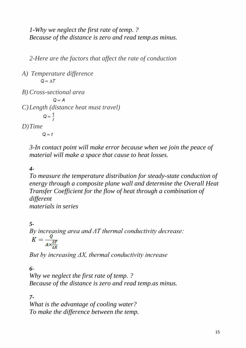
We find the cp and density in this tabe by temperature
http://www.engineeringtoolbox.com/water-thermal-properties-d_162.html
For Q=40
Taverag = (Tin+Tout)/2
(21.3+31.8)/2 = 26.55 at this temperature(26.55)
cp=4.18 density=996.82
………….
For Q=70
cp=4.179
density=995.95
………….
15
1-Why we neglect the first rate of temp. ?
Because of the distance is zero and read temp.as minus.
2-Here are the factors that affect the rate of conduction
A) Temperature difference
B) Cross-sectional area
C) Length (distance heat must travel)
D) Time
3-In contact point will make error because when we join the peace of
material will make a space that cause to heat losses.
4-
To measure the temperature distribution for steady-state conduction of
energy through a composite plane wall and determine the Overall Heat
Transfer Coefficient for the flow of heat through a combination of
different
materials in series
5-
By increasing area and ΔT thermal conductivity decrease:
But by increasing ΔX, thermal conductivity increase
6-
Why we neglect the first rate of temp. ?
Because of the distance is zero and read temp.as minus.
7-
What is the advantage of cooling water?
To make the difference between the temp.
16
References:
1- www.laserspectroscopy.ucc.ie/PY3011/Manual_HeatCo
nd.pdf
2- http://www.gunt.de/static/WL372
3- http://www.engineeringtoolbox.com/water-thermal-
properties-d_162.html