Embed Size (px)
Citation preview

Product Manual
3HAC 2941-1
IRB 6400
M98

The information in this document is subject to change without notice and should not be construed as a commitment by ABB Robotics Products AB. ABB Robotics Products AB assumes no responsibility for any errors that may appear in this document.
In no event shall ABB Robotics Products AB be liable for incidental or consequential damages arising from use of this document or of the software and hardware described in this document.
This document and parts thereof must not be reproduced or copied without ABB Robotics Products AB´s written permission, and contents thereof must not be imparted to a third party nor be used for any unauthorized purpose. Contravention will be prosecuted.
Additional copies of this document may be obtained from ABB Robotics Products AB at its then current charge.
© ABB Robotics Products AB
Article number: 3HAC 7677-1Issue: M2000/Rev.1
ABB Robotics Products ABS-721 68 Västerås
Sweden
Introduction Installation and Commissioning
Product Specification IRB 6400 Maintenance
Product Specification RobotWare Troubleshooting Tools
Safety Fault tracing guide
CE-declaration Circuit Diagram
Configuration List Repairs
System Description Spare parts
ABB Flexible Automation ABProduct Manual IRB 6400 M98, On-line Manual
MAIN MENU

Description
20 Product Specification IRB 1400 M97A/BaseWare OS 3.0

Introduction
CONTENTSPage
1 How to use this Manual........................................................................................... 3
2 What you must know before you use the Robot ................................................... 3
3 Identification ............................................................................................................ 4
Product Manual 1

Introduction
2 Product Manual
Introduction
ot
r on
d in onsult l to
e.
e ired,
the -cted to the
ut e
Introduction
1 How to use this Manual
This manual provides information on installation, preventive maintenance, trouble-shooting and how to carry out repairs on the manipulator and controller. Its intended audience is trained maintenance personnel with expertise in both mechanical and electrical systems. The manual does not in any way assume to take the place of the maintenance course offered by ABB Flexible Automation.
Anyone reading this manual should also have access to the User’s Guide.
The chapter entitled System Description provides general information on the robstructure, such as its computer system, input and output signals, etc.
How to assemble the robot and install all signals, etc., is described in the chapteInstallation and Commissioning.
If an error should occur in the robot system, you can find out why it has happenethe chapter on Troubleshooting. If you receive an error message, you can also cthe chapter on System and Error Messages in the User’s Guide. It is very helpfuhave a copy of the circuit diagram at hand when trying to locate cabling faults.
Servicing and maintenance routines are described in the chapter on Maintenanc
2 What you must know before you use the Robot
• Normal maintenance and repair work usually only require standard tools. Somrepairs, however, require specific tools. These repairs, and the type of tool requare described in more detail in the chapter Repairs.
• The power supply must always be switched off whenever work is carried out incontroller cabinet. Note that even though the power is switched off, the orangecoloured cables may be live. The reason for this is that these cables are conneexternal equipment and are consequently not affected by the mains switch on controller.
• Circuit boards - printed boards and components - must never be handled withoElectro-Static-Discharge (ESD) protection in order not to damage them. Use thcarry band located on the inside of the controller door.
All personnel working with the robot system must be very familiar with the safety regulations outlined in the chapter on Safety. Incorrect operation can damage the robot or injure someone.
Product Manual 3
Introduction
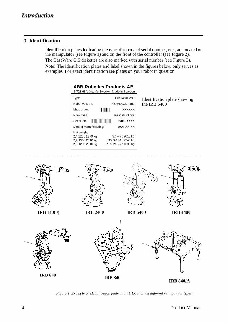
3 Identification
Identification plates indicating the type of robot and serial number, etc., are located on the manipulator (see Figure 1) and on the front of the controller (see Figure 2).The BaseWare O.S diskettes are also marked with serial number (see Figure 3). Note! The identification plates and label shown in the figures below, only serves as examples. For exact identification see plates on your robot in question.
Figure 1 Example of identification plate and it’s location on different manipulator types.
Made in SwedenS-721 68 Västerås SwedenABB Robotics Products AB
Type:
Robot version:
Man. order:
Nom. load
Serial. No:
Date of manufacturing:
Net weight2,4.120 : 1870 kg2,4-150 : 2010 kg2,8-120 : 2010 kg
IRB 6400 M98
IRB 6400/2.4-150
XXXXXX
See instructions
6400-XXXX
1997-XX-XX
3.0-75 : 2010 kgS/2,9-120 : 2240 kg
PE/2,25-75 : 1590 kg
Identification plate showing the IRB 6400
IRB 140(0) IRB 2400 IRB 4400
IRB 640
IRB 6400
IRB 840/AIRB 340
4 Product Manual
Introduction
.
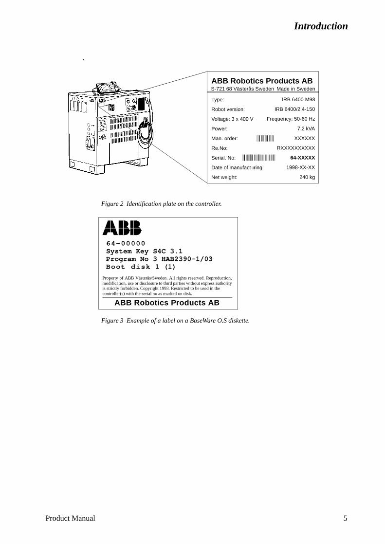
Figure 2 Identification plate on the controller.
Figure 3 Example of a label on a BaseWare O.S diskette.
Made in SwedenS-721 68 Västerås SwedenABB Robotics Products AB
Type:
Robot version:
Voltage: 3 x 400 V
Power:
Man. order:
Re.No:
Serial. No:
Date of manufacturing:
Net weight:
IRB 6400 M98
IRB 6400/2.4-150
Frequency: 50-60 Hz
7.2 kVA
XXXXXX
RXXXXXXXXXX
64-XXXXX
1998-XX-XX
240 kg
ABB Robotics Products AB
64-00000System Key S4C 3.1Program No 3 HAB2390-1/03Boot disk 1 (1)
Property of ABB Västerås/Sweden. All rights reserved. Reproduction,modification, use or disclosure to third parties without express authorityis strictly forbidden. Copyright 1993. Restricted to be used in the controller(s) with the serial no as marked on disk.
Product Manual 5

Introduction
6 Product Manual

Product Specification IRB 6400
CONTENTSPage
1 Introduction ..................................................................................................................... 3
2 Description ....................................................................................................................... 7
2.1 Structure.................................................................................................................. 7
2.2 Safety/Standards ..................................................................................................... 8
2.3 Operation ................................................................................................................ 9
2.4 Installation .............................................................................................................. 11
2.5 Programming .......................................................................................................... 12
2.6 Automatic Operation .............................................................................................. 14
2.7 Maintenance and Troubleshooting ......................................................................... 14
2.8 Robot Motion.......................................................................................................... 16
2.9 External Axes ......................................................................................................... 19
2.10 Inputs and Outputs................................................................................................ 19
2.11 Communication..................................................................................................... 20
3 Technical specification .................................................................................................... 21
3.1 Structure.................................................................................................................. 21
3.2 Safety/Standards ..................................................................................................... 25
3.3 Operation ................................................................................................................ 26
3.4 Installation .............................................................................................................. 27
3.5 Programming .......................................................................................................... 41
3.6 Automatic Operation .............................................................................................. 45
3.7 Maintenance and Troubleshooting ......................................................................... 45
3.8 Robot Motion.......................................................................................................... 46
3.9 External Axes ......................................................................................................... 49
3.10 Inputs and Outputs................................................................................................ 50
3.11 Communication..................................................................................................... 54
4 Specification of Variants and Options........................................................................... 55
5 Accessories ....................................................................................................................... 69
6 Index................................................................................................................................. 71
Product Specification IRB 6400 M98/BaseWare OS 3.1 1

Product Specification IRB 6400
2 Product Specification IRB 6400 M98/BaseWare OS 3.1
Introduction
t
g for apted
1 Introduction
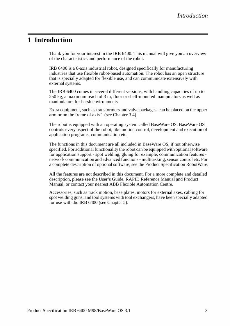
Thank you for your interest in the IRB 6400. This manual will give you an overview of the characteristics and performance of the robot.
IRB 6400 is a 6-axis industrial robot, designed specifically for manufacturing industries that use flexible robot-based automation. The robot has an open structure that is specially adapted for flexible use, and can communicate extensively with external systems.
The IRB 6400 comes in several different versions, with handling capacities of up to 250 kg, a maximum reach of 3 m, floor or shelf-mounted manipulators as well as manipulators for harsh environments.
Extra equipment, such as transformers and valve packages, can be placed on the upper arm or on the frame of axis 1 (see Chapter 3.4).
The robot is equipped with an operating system called BaseWare OS. BaseWare OS controls every aspect of the robot, like motion control, development and execution of application programs, communication etc.
The functions in this document are all included in BaseWare OS, if not otherwise specified. For additional functionality the robot can be equipped with optional software for application support - spot welding, gluing for example, communication features - network communication and advanced functions - multitasking, sensor control etc. For a complete description of optional software, see the Product Specification RobotWare.
All the features are not described in this document. For a more complete and detailed description, please see the User’s Guide, RAPID Reference Manual and ProducManual, or contact your nearest ABB Flexible Automation Centre.
Accessories, such as track motion, base plates, motors for external axes, cablinspot welding guns, and tool systems with tool exchangers, have been specially adfor use with the IRB 6400 (see Chapter 5).
Product Specification IRB 6400 M98/BaseWare OS 3.1 3
Introduction
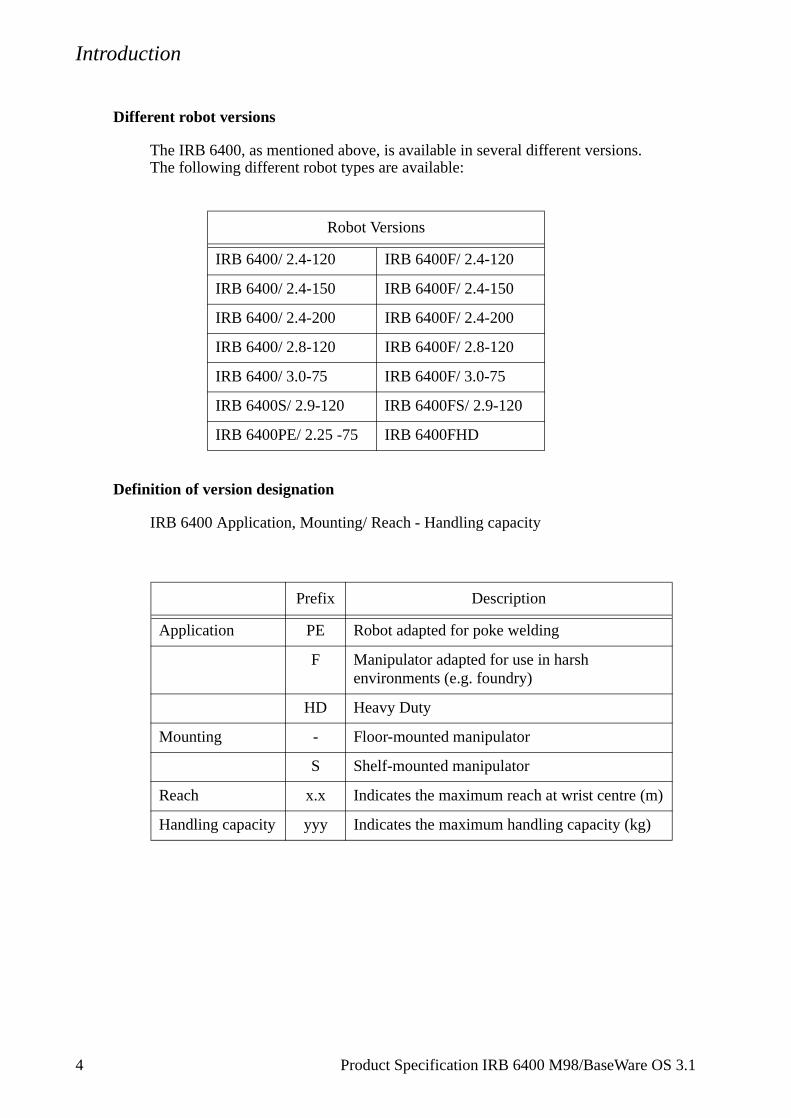
Different robot versions
The IRB 6400, as mentioned above, is available in several different versions.The following different robot types are available:
Definition of version designation
IRB 6400 Application, Mounting/ Reach - Handling capacity
Robot Versions
IRB 6400/ 2.4-120 IRB 6400F/ 2.4-120
IRB 6400/ 2.4-150 IRB 6400F/ 2.4-150
IRB 6400/ 2.4-200 IRB 6400F/ 2.4-200
IRB 6400/ 2.8-120 IRB 6400F/ 2.8-120
IRB 6400/ 3.0-75 IRB 6400F/ 3.0-75
IRB 6400S/ 2.9-120 IRB 6400FS/ 2.9-120
IRB 6400PE/ 2.25 -75 IRB 6400FHD
Prefix Description
Application PE Robot adapted for poke welding
F Manipulator adapted for use in harsh environments (e.g. foundry)
HD Heavy Duty
Mounting - Floor-mounted manipulator
S Shelf-mounted manipulator
Reach x.x Indicates the maximum reach at wrist centre (m)
Handling capacity yyy Indicates the maximum handling capacity (kg)
4 Product Specification IRB 6400 M98/BaseWare OS 3.1
Introduction
How to use this manual
The characteristics of the robot are described in Chapter 2: Description.
The most important technical data is listed in Chapter 3: Technical specification.
Note that the sections in chapters 2 and 3 are related to each other. For example, in section 2.2 you can find an overview of safety and standards, in section 3.2 you can find more detailed information.
To make sure that you have ordered a robot with the correct functionality, see Chapter 4: Specification of Variants and Options.
In Chapter 5 you will find accessories for the robot.
Chapter 6 contains an Index, to make things easier to find.
Other manuals
The User’s Guide is a reference manual with step by step instructions on how toperform various tasks.
The programming language is described in the RAPID Reference Manual.
The Product Manual describes how to install the robot, as well as maintenance procedures and troubleshooting.
The Product Specification RobotWare describes the software options.
Product Specification IRB 6400 M98/BaseWare OS 3.1 5

Introduction
6 Product Specification IRB 6400 M98/BaseWare OS 3.1
Description
2 Description
2.1 Structure
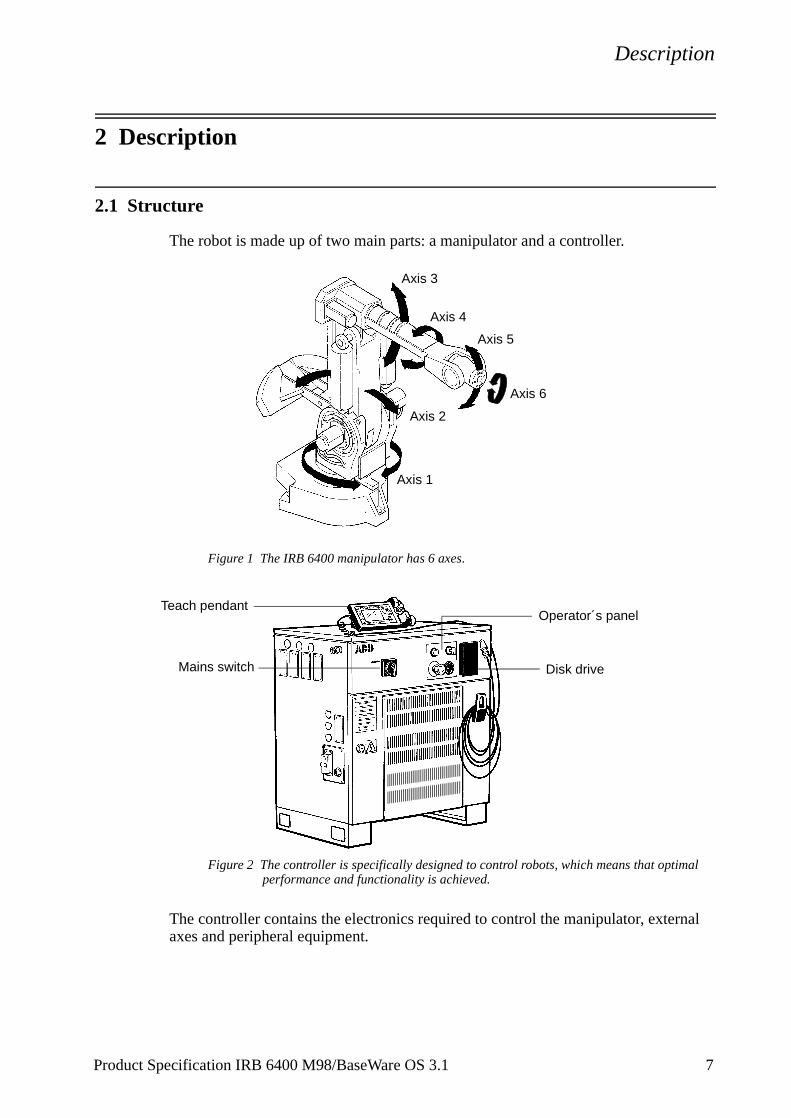
The robot is made up of two main parts: a manipulator and a controller.
Figure 1 The IRB 6400 manipulator has 6 axes.
Figure 2 The controller is specifically designed to control robots, which means that optimal performance and functionality is achieved.
The controller contains the electronics required to control the manipulator, external axes and peripheral equipment.
Axis 6
Axis 1
Axis 5
Axis 4
Axis 3
Axis 2
Teach pendantOperator´s panel
Disk driveMains switch
Product Specification IRB 6400 M98/BaseWare OS 3.1 7
Description
C’s
tem nt
next lty ery -
robot
.ts of obot.
in aning or
teach
ach ety
safety
rmal d the
also
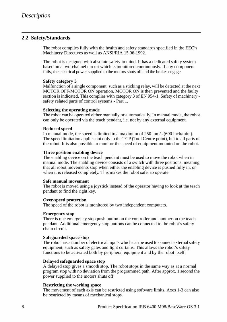
2.2 Safety/Standards
The robot complies fully with the health and safety standards specified in the EEMachinery Directives as well as ANSI/RIA 15.06-1992.
The robot is designed with absolute safety in mind. It has a dedicated safety sysbased on a two-channel circuit which is monitored continuously. If any componefails, the electrical power supplied to the motors shuts off and the brakes engage.
Safety category 3Malfunction of a single component, such as a sticking relay, will be detected at theMOTOR OFF/MOTOR ON operation. MOTOR ON is then prevented and the fausection is indicated. This complies with category 3 of EN 954-1, Safety of machinsafety related parts of control systems - Part 1.
Selecting the operating mode The robot can be operated either manually or automatically. In manual mode, thecan only be operated via the teach pendant, i.e. not by any external equipment.
Reduced speedIn manual mode, the speed is limited to a maximum of 250 mm/s (600 inch/min.)The speed limitation applies not only to the TCP (Tool Centre point), but to all parthe robot. It is also possible to monitor the speed of equipment mounted on the r
Three position enabling deviceThe enabling device on the teach pendant must be used to move the robot whenmanual mode. The enabling device consists of a switch with three positions, methat all robot movements stop when either the enabling device is pushed fully in,when it is released completely. This makes the robot safer to operate.
Safe manual movementThe robot is moved using a joystick instead of the operator having to look at the pendant to find the right key.
Over-speed protectionThe speed of the robot is monitored by two independent computers.
Emergency stopThere is one emergency stop push button on the controller and another on the tependant. Additional emergency stop buttons can be connected to the robot’s safchain circuit.
Safeguarded space stopThe robot has a number of electrical inputs which can be used to connect externalequipment, such as safety gates and light curtains. This allows the robot’s safetyfunctions to be activated both by peripheral equipment and by the robot itself.
Delayed safeguarded space stopA delayed stop gives a smooth stop. The robot stops in the same way as at a noprogram stop with no deviation from the programmed path. After approx. 1 seconpower supplied to the motors shuts off.
Restricting the working space The movement of each axis can be restricted using software limits. Axes 1-3 canbe restricted by means of mechanical stops.
8 Product Specification IRB 6400 M98/BaseWare OS 3.1
Description
When ting
ry)
ipula-
dant
and earn nt, the
Hold-to-run control“Hold-to-run” means that you must depress the start button in order to move the robot. the button is released the robot will stop. The hold-to-run function makes program tessafer.
Fire safetyBoth the manipulator and control system comply with UL’s (Underwriters Laboratotough requirements for fire safety.
Safety lampAs an option, the robot can be equipped with a safety lamp mounted on the mantor. This is activated when the motors are in the MOTORS ON state.
2.3 Operation
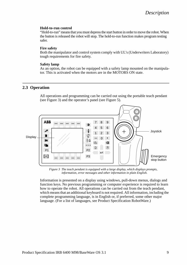
All operations and programming can be carried out using the portable teach pen(see Figure 3) and the operator’s panel (see Figure 5).
Figure 3 The teach pendant is equipped with a large display, which displays prompts, information, error messages and other information in plain English.
Information is presented on a display using windows, pull-down menus, dialogs function keys. No previous programming or computer experience is required to lhow to operate the robot. All operations can be carried out from the teach pendawhich means that an additional keyboard is not required. All information, includingcomplete programming language, is in English or, if preferred, some other majorlanguage. (For a list of languages, see Product Specification RobotWare.)
21
2 3
0
1
4 5 6
7 8 9
P3
P1 P2
Joystick
Display
Emergency stop button
Product Specification IRB 6400 M98/BaseWare OS 3.1 9
Description
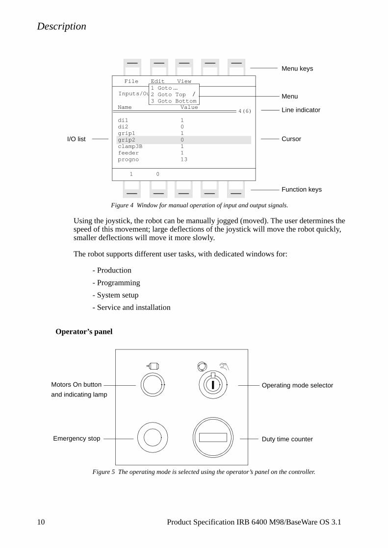
Figure 4 Window for manual operation of input and output signals.
Using the joystick, the robot can be manually jogged (moved). The user determines the speed of this movement; large deflections of the joystick will move the robot quickly, smaller deflections will move it more slowly.
The robot supports different user tasks, with dedicated windows for:
- Production
- Programming
- System setup
- Service and installation
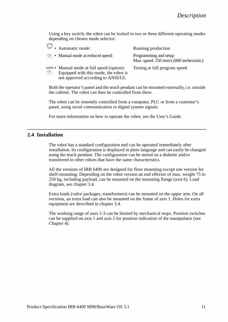
Operator’s panel
Figure 5 The operating mode is selected using the operator’s panel on the controller.
Inputs/Outputs
File
Value
10101113
Edit View
1 0
4(6)Name
di1di2grip1grip2clamp3Bfeederprogno
1 Goto ...2 Goto Top3 Goto Bottom
Menu keys
I/O list
Menu
Line indicator
Cursor
Function keys
Operating mode selector
Duty time counter
Motors On button
Emergency stop
and indicating lamp
10 Product Specification IRB 6400 M98/BaseWare OS 3.1
Description
utside
s
nged
for 5 to
d
n all tra
tches ee
Using a key switch, the robot can be locked in two or three different operating modes depending on chosen mode selector:
• Automatic mode: Running production
• Manual mode at reduced speed: Programming and setupMax. speed: 250 mm/s (600 inches/min.)
• Manual mode at full speed (option): Testing at full program speedEquipped with this mode, the robot is not approved according to ANSI/UL
Both the operator’s panel and the teach pendant can be mounted externally, i.e. othe cabinet. The robot can then be controlled from there.
The robot can be remotely controlled from a computer, PLC or from a customer’panel, using serial communication or digital system signals.
For more information on how to operate the robot, see the User’s Guide.
2.4 Installation
The robot has a standard configuration and can be operated immediately after installation. Its configuration is displayed in plain language and can easily be chausing the teach pendant. The configuration can be stored on a diskette and/or transferred to other robots that have the same characteristics.
All the versions of IRB 6400 are designed for floor mounting except one versionshelf-mounting. Depending on the robot version an end effector of max. weight 7250 kg, including payload, can be mounted on the mounting flange (axis 6). Loadiagram, see chapter 3.4.
Extra loads (valve packages, transformers) can be mounted on the upper arm. Oversions, an extra load can also be mounted on the frame of axis 1. Holes for exequipment are described in chapter 3.4.
The working range of axes 1-3 can be limited by mechanical stops. Position swican be supplied on axis 1 and axis 2 for position indication of the manipulator (sChapter 4).
100%
Product Specification IRB 6400 M98/BaseWare OS 3.1 11
Description
mber
nt.
tc.
ithout
using
tween
to the
size and
2.5 Programming
Programming the robot involves choosing instructions and arguments from lists of appropriate alternatives. Users do not need to remember the format of instructions, since they are prompted in plain English. “See and pick” is used instead of “remeand type”.
The programming environment can be easily customized using the teach penda
- Shop floor language can be used to name programs, signals, counters, e
- New instructions can be easily written.
- The most common instructions can be collected in easy-to-use pick lists.
- Positions, registers, tool data, or other data, can be created.
Programs, parts of programs and any modifications can be tested immediately whaving to translate (compile) the program.
The program is stored as a normal PC text file, which means that it can be editeda standard PC.
Movements
A sequence of movements is programmed as a number of partial movements bethe positions to which you want the robot to move.
The end position of a movement is selected either by manually jogging the robot desired position with the joystick, or by referring to a previously defined position.
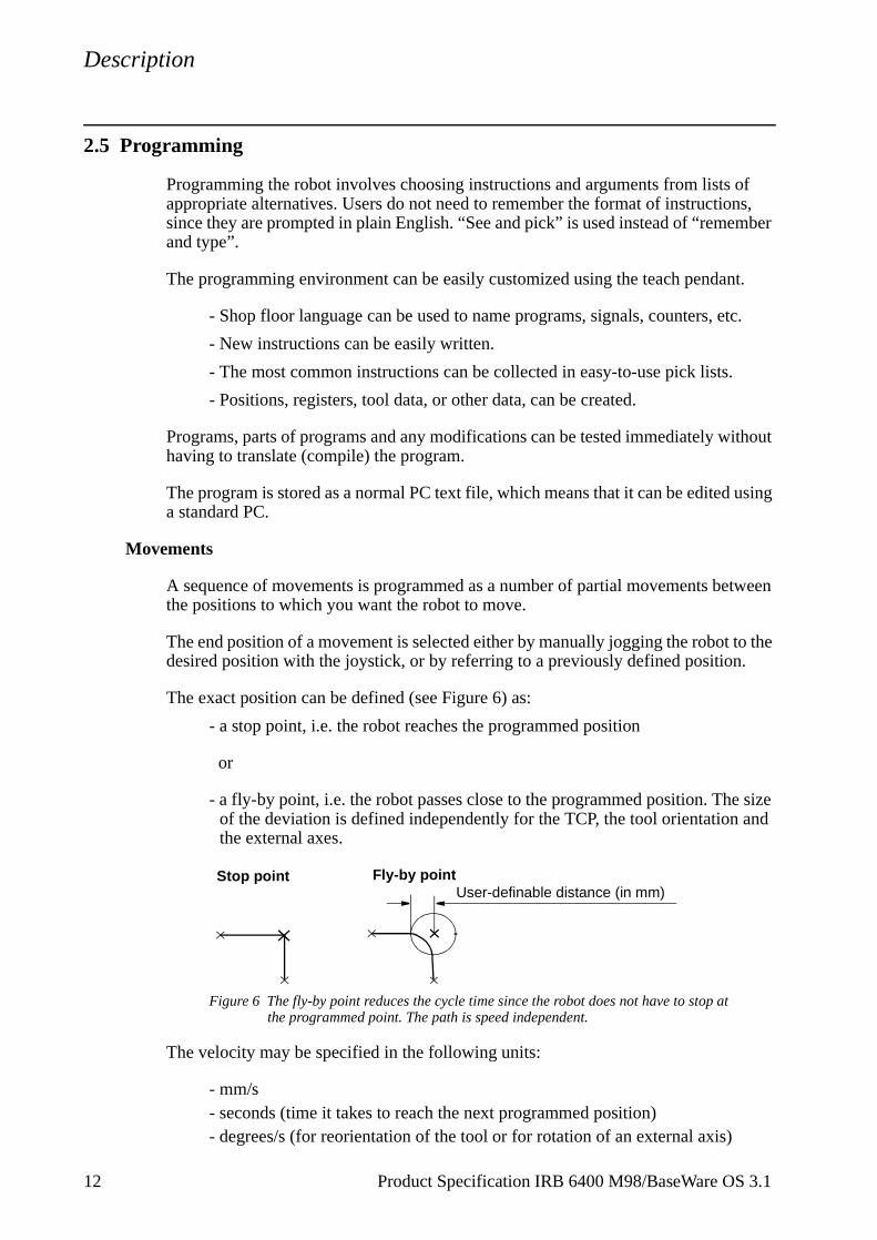
The exact position can be defined (see Figure 6) as:
- a stop point, i.e. the robot reaches the programmed position
or
- a fly-by point, i.e. the robot passes close to the programmed position. Theof the deviation is defined independently for the TCP, the tool orientation the external axes.
Figure 6 The fly-by point reduces the cycle time since the robot does not have to stop atthe programmed point. The path is speed independent.
The velocity may be specified in the following units:
- mm/s - seconds (time it takes to reach the next programmed position)- degrees/s (for reorientation of the tool or for rotation of an external axis)
Stop point Fly-by pointUser-definable distance (in mm)
12 Product Specification IRB 6400 M98/BaseWare OS 3.1
Description
is
rams
PC
copy, o be
since
an be
Program management
For convenience, the programs can be named and stored in different directories.
Areas of the robot’s program memory can also be used for program storage. Thprovides fast memory for program storage. These can then be automatically downloaded using a program instruction. The complete program or parts of progcan be transferred to/from a diskette.
Programs can be printed on a printer connected to the robot, or transferred to a where they can be edited or printed later.
Editing programs
Programs can be edited using standard editing commands, i.e. “cut-and-paste”,delete, find and change, undo etc. Individual arguments in an instruction can alsedited using these commands.
No reprogramming is necessary when processing left-hand and right-hand parts,the program can be mirrored in any plane.
A robot position can easily be changed either by
- jogging the robot with the joystick to a new position and then pressing the“ModPos” key (this registers the new position)
or by
- entering or modifying numeric values.
To prevent unauthorised personnel from making program changes, passwords cused.
Testing programs
Several helpful functions can be used when testing programs. For example, it ispossible to
- start from any instruction- execute an incomplete program- run a single cycle- execute forward/backward step-by-step - simulate wait conditions- temporarily reduce the speed- change a position- tune (displace) a position during program execution.
For more information, see the User’s Guide and RAPID Reference Manual.
Product Specification IRB 6400 M98/BaseWare OS 3.1 13
Description
2.6 Automatic Operation
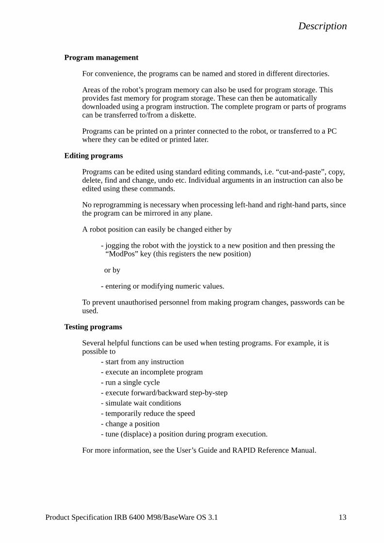
A dedicated production window with commands and information required by the operator is automatically displayed during automatic operation.
The operation procedure can be customised to suit the robot installation by means of user-defined operating dialogs.
Figure 7 The operator dialogs can be easily customised.
A special input can be set to order the robot to go to a service position. After service, the robot is ordered to return to the programmed path and continue program execution.
You can also create special routines that will be automatically executed when the power is switched on, at program start and on other occasions. This allows you to customise each installation and to make sure that the robot is started up in a controlled way.
The robot is equipped with absolute measurement, making it possible to operate the robot directly when the power is switched on. For your convenience, the robot saves the used path, program data and configuration parameters so that the program can be easily restarted from where you left off. Digital outputs are also set automatically to the value prior to the power failure.
2.7 Maintenance and Troubleshooting
The robot requires only a minimum of maintenance during operation. It has been designed to make it as easy to service as possible:
- The controller is enclosed, which means that the electronic circuitry is protected when operating in a normal workshop environment.
- Maintenance-free AC motors are used.
- Liquid grease or oil is used for the gear boxes.
- The cabling is routed for longevity, and in the unlikely event of a failure, its modular design makes it easy to change.
- It has a program memory “battery low” alarm.
Front A Front B Front C Other SERVICE
Select program to run:
14 Product Specification IRB 6400 M98/BaseWare OS 3.1
Description
The robot has several functions to provide efficient diagnostics and error reports:
- It performs a self-test when power on is set.
- Errors are indicated by a message displayed in plain language. The message includes the reason for the fault and suggests recovery action.
- A board error is indicated by a LED on the faulty unit.
- Faults and major events are logged and time-stamped. This makes it possible to detect error chains and provides the background for any downtime. The log can be read on the teach pendant display, stored in a file or printed on a printer.
- There are commands and service programs in RAPID to test units and functions.
Most errors detected by the user program can also be reported to and handled by the standard error system. Error messages and recovery procedures are displayed in plain language.
Product Specification IRB 6400 M98/BaseWare OS 3.1 15
Description
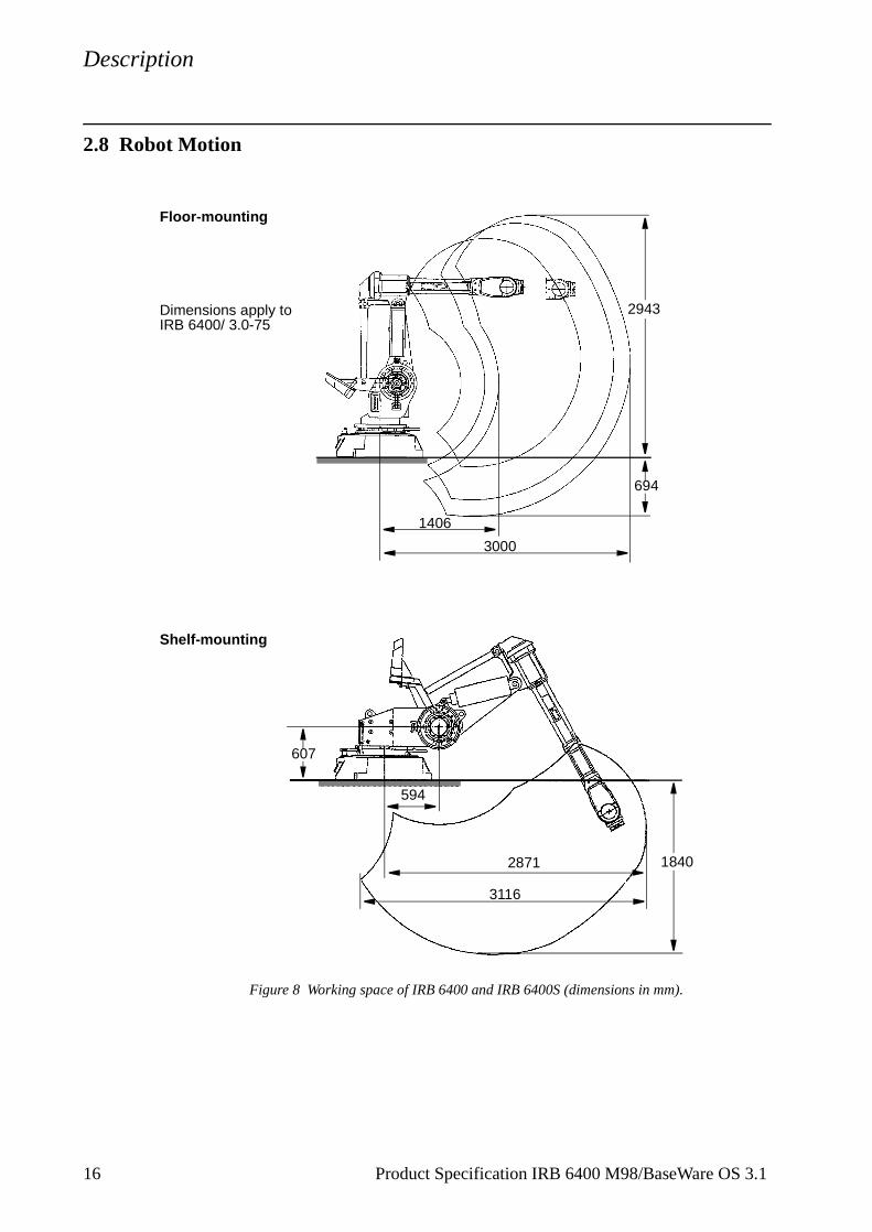
2.8 Robot Motion
Figure 8 Working space of IRB 6400 and IRB 6400S (dimensions in mm).
Floor-mounting
694
1406
3000
Dimensions apply toIRB 6400/ 3.0-75
2943
Shelf-mounting
3116
2871
594
607
1840
16 Product Specification IRB 6400 M98/BaseWare OS 3.1
Description
ss of op, a
e two
le to stem
t.
Motion performance
The QuickMoveTM concept means that a self-optimizing motion control is used. The robot automatically optimizes the servo parameters to achieve the best possible performance throughout the cycle - based on load properties, location in working area, velocity and direction of movement.
- No parameters have to be adjusted to achieve correct path, orientation and velocity.
- Maximum acceleration is always obtained (acceleration can be reduced, e.g. when handling fragile parts).
- The number of adjustments that have to be made to achieve the shortest possible cycle time is minimized.
The TrueMoveTM concept means that the programmed path is followed – regardlethe speed or operating mode – even after an emergency stop, a safeguarded stprocess stop, a program stop or a power failure.
The robot can, in a controlled way, pass through singular points, i.e. points wheraxes coincide.
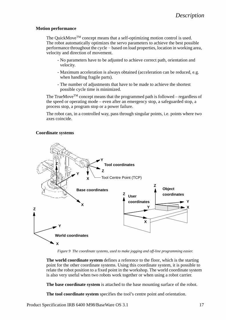
Coordinate systems
Figure 9 The coordinate systems, used to make jogging and off-line programming easier.
The world coordinate system defines a reference to the floor, which is the startingpoint for the other coordinate systems. Using this coordinate system, it is possibrelate the robot position to a fixed point in the workshop. The world coordinate syis also very useful when two robots work together or when using a robot carrier.
The base coordinate system is attached to the base mounting surface of the robo
The tool coordinate system specifies the tool’s centre point and orientation.
Object
Z
Y
X
World coordinates
User Z
Z
YY
X
Xcoordinates
coordinates
X
Y
Base coordinates
Tool coordinates Y
Z
Tool Centre Point (TCP)X
Z
Product Specification IRB 6400 M98/BaseWare OS 3.1 17
Description
nd ld
be
sible peed
n - ection
ion djust
ate
an be ance
an be
The user coordinate system specifies the position of a fixture or workpiece manipulator.
The object coordinate system specifies how a workpiece is positioned in a fixture or workpiece manipulator.
The coordinate systems can be programmed by specifying numeric values or jogging the robot through a number of positions (the tool does not have to be removed).
Each position is specified in object coordinates with respect to the tool’s position aorientation. This means that even if a tool is changed because it is damaged, the oprogram can still be used, unchanged, by making a new definition of the tool. If a fixture or workpiece is moved, only the user or object coordinate system has toredefined.
Stationary TCP
When the robot is holding a work object and working on a stationary tool, it is posto define a TCP for that tool. When that tool is active, the programmed path and sare related to the work object.
Program execution
The robot can move in any of the following ways:
- Joint motion (all axes move individually and reach the programmed position at the same time)
- Linear motion (the TCP moves in a linear path)
- Circle motion (the TCP moves in a circular path)
Soft servo - allowing external forces to cause deviation from programmed positiocan be used as an alternative to mechanical compliance in grippers, where imperfin processed objects can occur.
If the location of a workpiece varies from time to time, the robot can find its positby means of a digital sensor. The robot program can then be modified in order to athe motion to the location of the part.
Jogging
The robot can be manually operated in any one of the following ways:
- Axis-by-axis, i.e. one axis at a time
- Linearly, i.e. the TCP moves in a linear path (relative to one of the coordinsystems mentioned above)
- Reoriented around the TCP
It is possible to select the step size for incremental jogging. Incremental jogging cused to position the robot with high precision, since the robot moves a short disteach time the joystick is moved.
During manual operation, the current position of the robot and the external axes cdisplayed on the teach pendant.
18 Product Specification IRB 6400 M98/BaseWare OS 3.1
Description
,
is
mple, nt e drive
ither he
a
s to be
tion,
see
2.9 External Axes
The robot can control up to six external axes. These axes are programmed and moved using the teach pendant in the same way as the robot’s axes.
The external axes can be grouped into mechanical units to facilitate, for examplethe handling of robot carriers, workpiece manipulators, etc.
The robot motion can be simultaneously coordinated with for example, a one-axlinear robot carrier and a rotational external axis.
A mechanical unit can be activated or deactivated to make it safe when, for examanually changing a workpiece located on the unit. In order to reduce investmecosts, any axes that do not have to be active at the same time, can share the samunit.
2.10 Inputs and Outputs
A distributed I/O system is used, which makes it possible to mount the I/O units einside the cabinet or outside the cabinet with a cable connecting the I/O unit to tcabinet.
A number of different input and output units can be installed:
- Digital inputs and outputs.
- Analog inputs and outputs.
- Remote I/O for Allen-Bradley PLC.
- InterBus-S Slave.
- Profibus DP Slave.
The inputs and outputs can be configured to suit your installation:
- Each signal and unit can be given a name, e.g. gripper, feeder.
- I/O mapping (i.e. a physical connection for each signal).
- Polarity (active high or low).
- Cross connections.
- Up to 16 digital signals can be grouped together and used as if they weresingle signal when, for example, entering a bar code.
Signals can be assigned to special system functions, such as program start, so aable to control the robot from an external panel or PLC.
The robot can work as a PLC by monitoring and controlling I/O signals:
- I/O instructions can be executed concurrent to the robot motion.
- Inputs can be connected to trap routines. (When such an input is set, thetrap routine starts executing. Following this, normal program execution resumes. In most cases, this will not have any visible effect on the robot moi.e. if a limited number of instructions are executed in the trap routine.)
- Background programs (for monitoring signals, for example) can be run in parallel with the actual robot program. Requires Multitasking option, Product Specification RobotWare.
Product Specification IRB 6400 M98/BaseWare OS 3.1 19
Description
Manual functions are available to:
- List all the signal values.
- Create your own list of your most important signals.
- Manually change the status of an output signal.
- Print signal information on a printer.
I/O signals can also be routed to connectors on the upper arm of the robot.
2.11 Communication
The robot can communicate with computers or other equipment via RS232/RS422 serial channels or via Ethernet. However this requires optional software, see Product Specification RobotWare.
20 Product Specification IRB 6400 M98/BaseWare OS 3.1
Technical specification
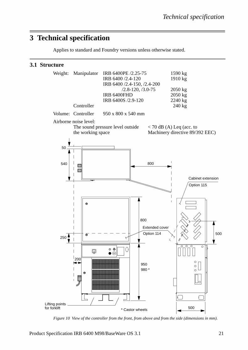
3 Technical specification
Applies to standard and Foundry versions unless otherwise stated.
3.1 StructureWeight: Manipulator IRB 6400PE /2.25-75 1590 kg
IRB 6400 /2.4-120 1910 kg IRB 6400 /2.4-150, /2.4-200
/2.8-120, /3.0-75 2050 kg IRB 6400FHD 2050 kgIRB 6400S /2.9-120 2240 kg
Controller 240 kg
Volume: Controller 950 x 800 x 540 mm
Airborne noise level:The sound pressure level outside < 70 dB (A) Leq (acc. tothe working space Machinery directive 89/392 EEC)
Figure 10 View of the controller from the front, from above and from the side (dimensions in mm).
200
50
540
950980 *
500
500
800
Lifting pointsfor forklift * Castor wheels
800
250
Extended cover
Option 114
Cabinet extension
Option 115
Product Specification IRB 6400 M98/BaseWare OS 3.1 21
Technical specification
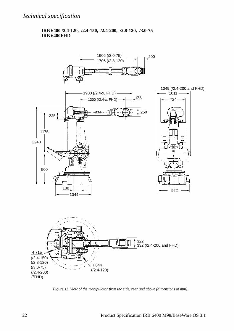
IRB 6400 /2.4-120, /2.4-150, /2.4-200, /2.8-120, /3.0-75IRB 6400FHD
Figure 11 View of the manipulator from the side, rear and above (dimensions in mm).
1906 (/3.0-75)1705 (/2.8-120)
1300 (/2.4-x, FHD)
2240
1011
9221044
322
2001900 (/2.4-x, FHD)
R 644
R 715
200
188
(/2.4-120)
(/2.4-150)(/2.8-120)(/3.0-75)
250
900
1175
225
724
332 (/2.4-200 and FHD)
1049 (/2.4-200 and FHD)
(/2.4-200)(/FHD)
22 Product Specification IRB 6400 M98/BaseWare OS 3.1
Technical specification
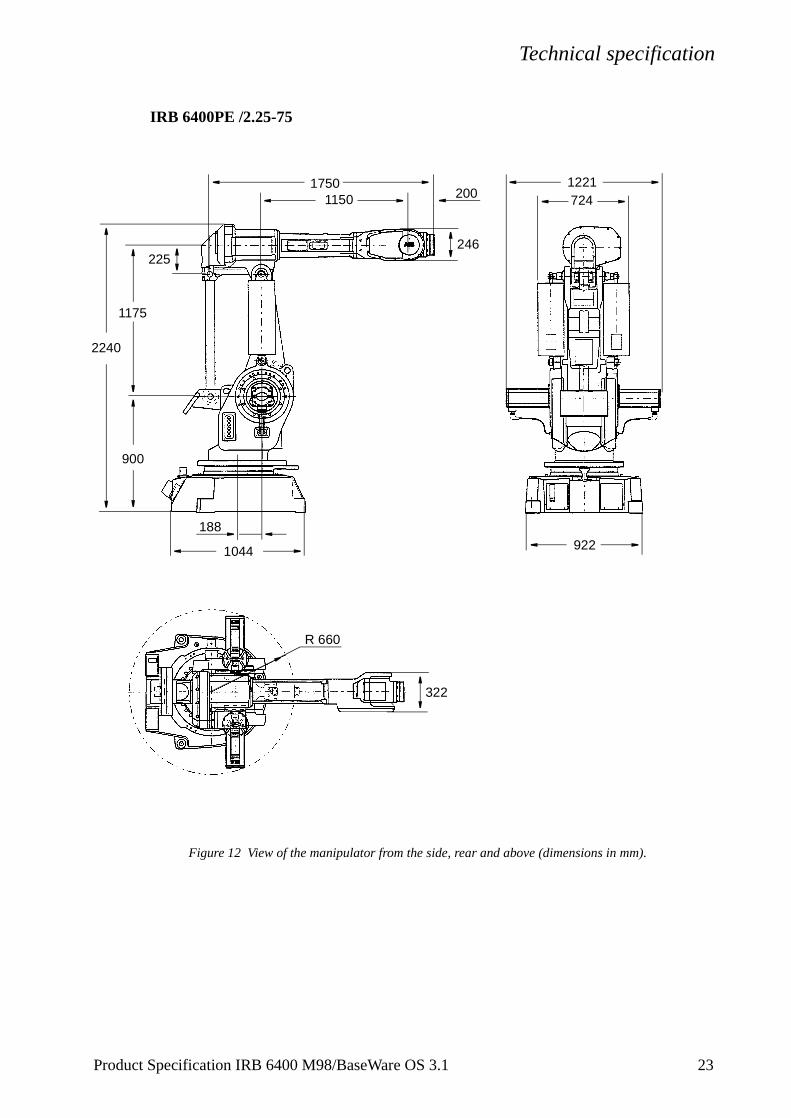
IRB 6400PE /2.25-75
Figure 12 View of the manipulator from the side, rear and above (dimensions in mm).
1150
R 660
322
922
1221200
1750
1044
2240
188
900
1175
225246
724
Product Specification IRB 6400 M98/BaseWare OS 3.1 23

Technical specification
IRB 6400S /2.9-120
Figure 13 View of the manipulator from the side and rear (dimensions in mm).The robot is shown in its calibration position.
400
1705
200
1044
1031525 506
922
950
225165
1340
607
594
250
24 Product Specification IRB 6400 M98/BaseWare OS 3.1
Technical specification
y stop
.
3.2 Safety/Standards
The robot conforms to the following standards:
EN 292-1 Safety of machinery, terminology
EN 292-2 Safety of machinery, technical specifications
EN 954-1 Safety of machinery, safety related parts of control systems
EN 60204 Electrical equipment of industrial machines
IEC 204-1 Electrical equipment of industrial machines
ISO 10218, EN 775 Manipulating industrial robots, safety
ANSI/RIA 15.06/1992 Industrial robots, safety requirements
ISO 9409-1 Manipulating industrial robots, mechanical interface
ISO 9787 Manipulating industrial robots, coordinate systemsand motions
IEC 529 Degrees of protection provided by enclosures
EN 50081-2 EMC, Generic emission
EN 50082-2 EMC, Generic immunity
ANSI/UL 1740-1996 (option) Safety Standard for Industrial Robots and Robotic Equipment
CAN/CSA Z 424-94 (option) Industrial Robots and Robot Systems - General Safety Requirements
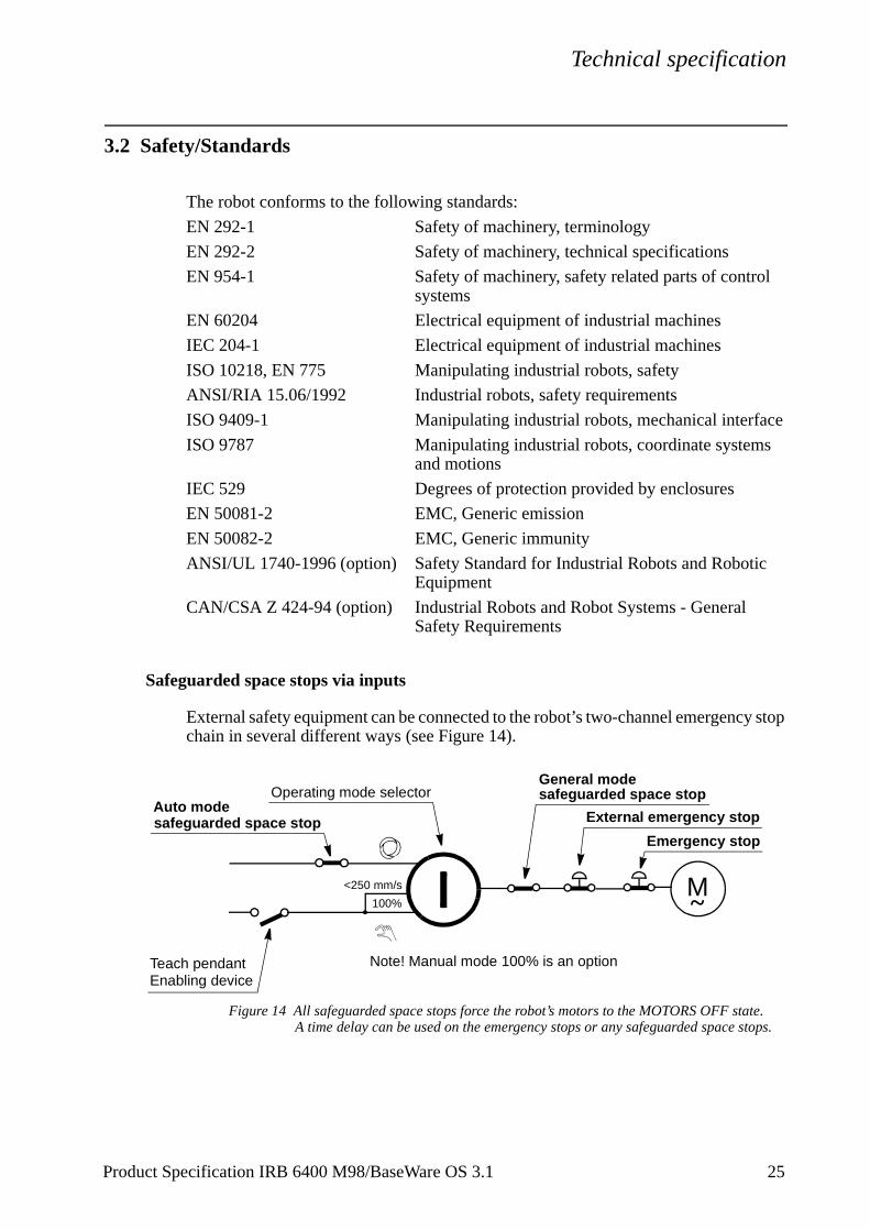
Safeguarded space stops via inputs
External safety equipment can be connected to the robot’s two-channel emergencchain in several different ways (see Figure 14).
Figure 14 All safeguarded space stops force the robot’s motors to the MOTORS OFF stateA time delay can be used on the emergency stops or any safeguarded space stops.
<250 mm/s
100%
Emergency stop
Auto mode
General modeOperating mode selector
M~
safeguarded space stop
safeguarded space stop
Teach pendant
External emergency stop
Note! Manual mode 100% is an optionEnabling device
Product Specification IRB 6400 M98/BaseWare OS 3.1 25
Technical specification
2
/close
3.3 Operation
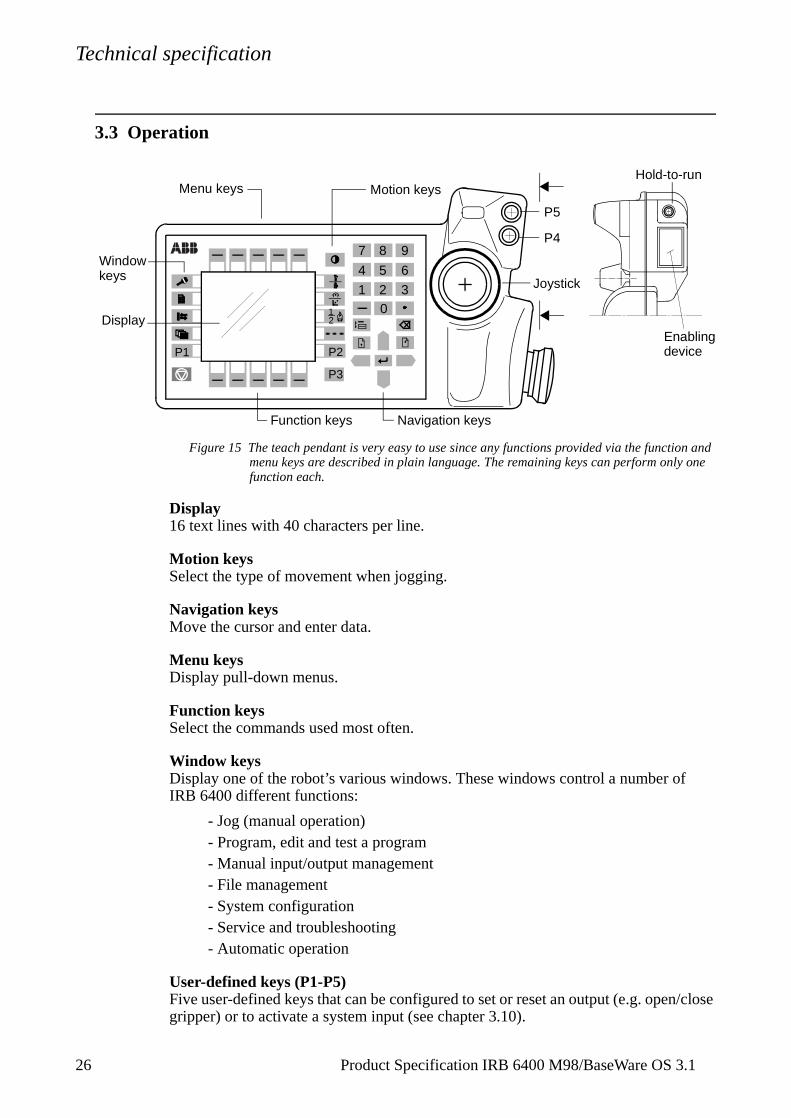
Figure 15 The teach pendant is very easy to use since any functions provided via the function and menu keys are described in plain language. The remaining keys can perform only one function each.
Display16 text lines with 40 characters per line.
Motion keysSelect the type of movement when jogging.
Navigation keysMove the cursor and enter data.
Menu keysDisplay pull-down menus.
Function keysSelect the commands used most often.
Window keysDisplay one of the robot’s various windows. These windows control a number ofIRB 6400 different functions:
- Jog (manual operation)- Program, edit and test a program- Manual input/output management- File management- System configuration- Service and troubleshooting- Automatic operation
User-defined keys (P1-P5)Five user-defined keys that can be configured to set or reset an output (e.g. opengripper) or to activate a system input (see chapter 3.10).
21
2 30
1
4 5 6
7 8 9
P3
P1 P2
Hold-to-run
Enabling
P4
P5
device
Joystick
Function keys
Motion keysMenu keys
Window
Navigation keys
Display
keys
6 Product Specification IRB 6400 M98/BaseWare OS 3.1
Technical specification
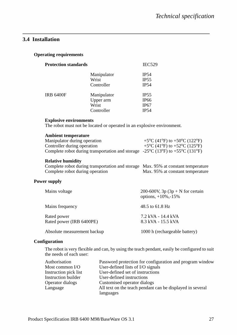
3.4 Installation
Operating requirements
Protection standards IEC529
Manipulator IP54Wrist IP55Controller IP54
IRB 6400F Manipulator IP55Upper arm IP66Wrist IP67Controller IP54
Explosive environmentsThe robot must not be located or operated in an explosive environment.
Ambient temperatureManipulator during operation +5oC (41oF) to +50oC (122oF)Controller during operation +5oC (41oF) to +52oC (125oF)Complete robot during transportation and storage -25oC (13oF) to +55oC (131oF)
Relative humidityComplete robot during transportation and storage Max. 95% at constant temperatureComplete robot during operation Max. 95% at constant temperature
Power supply
Mains voltage 200-600V, 3p (3p + N for certain options, +10%,-15%
Mains frequency 48.5 to 61.8 Hz
Rated power 7.2 kVA - 14.4 kVARated power (IRB 6400PE) 8.3 kVA - 15.5 kVA
Absolute measurement backup 1000 h (rechargeable battery)
Configuration
The robot is very flexible and can, by using the teach pendant, easily be configured to suit the needs of each user:
Authorisation Password protection for configuration and program windowMost common I/O User-defined lists of I/O signalsInstruction pick list User-defined set of instructionsInstruction builder User-defined instructionsOperator dialogs Customised operator dialogsLanguage All text on the teach pendant can be displayed in several
languages
Product Specification IRB 6400 M98/BaseWare OS 3.1 27
Technical specification
2
Date and time Calendar supportPower on sequence Action taken when the power is switched onEM stop sequence Action taken at an emergency stopMain start sequence Action taken when the program is
starting from the beginningProgram start sequence Action taken at program startProgram stop sequence Action taken at program stopChange program sequence Action taken when a new program is loadedWorking space Working space limitationsExternal axes Number, type, common drive unit, mechanical unitsBrake delay time Time before brakes are engagedI/O signal Logical names of boards and signals, I/O mapping,
cross connections, polarity, scaling, default value at start up, interrupts, group I/O
Serial communication Configuration
For a detailed description of the installations procedure, see the Product Manual - Installation and Commissioning.
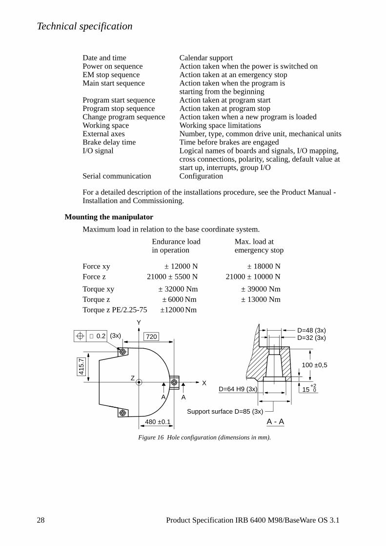
Mounting the manipulator
Maximum load in relation to the base coordinate system.
Endurance load Max. load at in operation emergency stop
Force xy ± 12000 N ± 18000 NForce z 21000 ± 5500 N 21000 ± 10000 N
Torque xy ± 32000 Nm ± 39000 NmTorque z ± 6000 Nm ± 13000 NmTorque z PE/2.25-75 ±12000 Nm
Figure 16 Hole configuration (dimensions in mm).
Support surface D=85 (3x)
A
0.2 720
480 ±0.1
A
∅
415.
7
D=32 (3x)D=48 (3x)
D=64 H9 (3x)
A - A
X
Y
Z
100 ±0,5
15+2
0
(3x)
8 Product Specification IRB 6400 M98/BaseWare OS 3.1
Technical specification
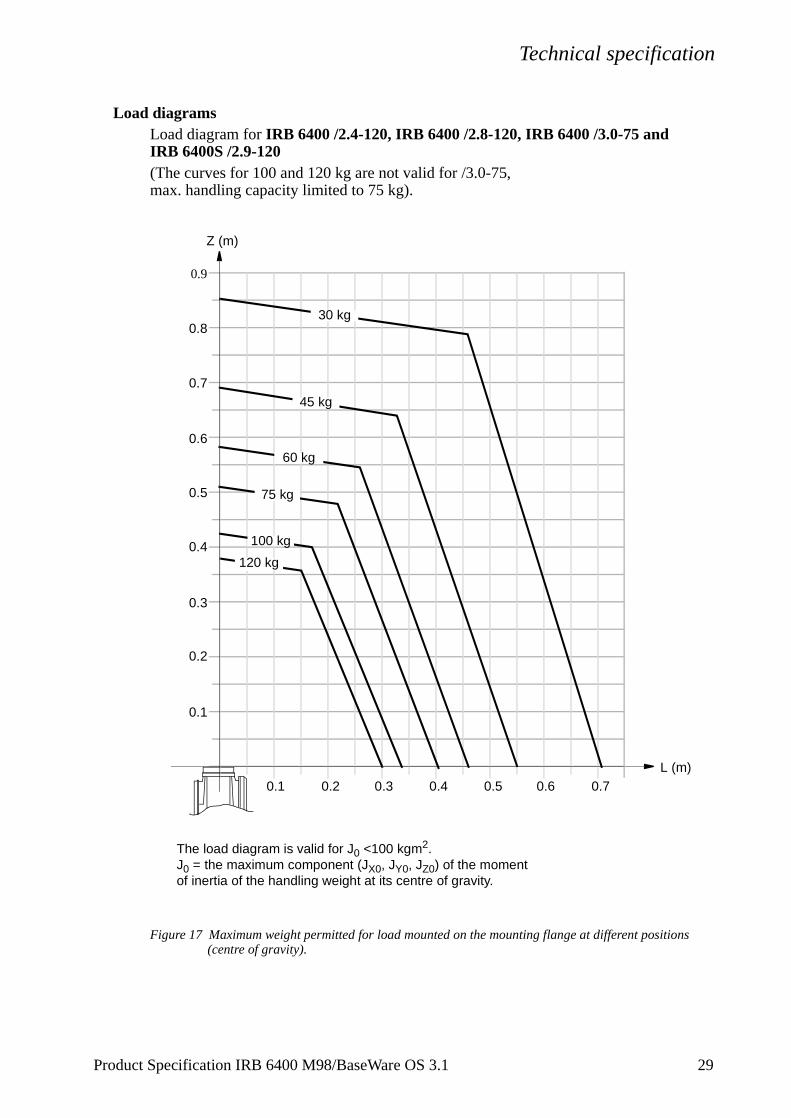
Load diagramsLoad diagram for IRB 6400 /2.4-120, IRB 6400 /2.8-120, IRB 6400 /3.0-75 and IRB 6400S /2.9-120(The curves for 100 and 120 kg are not valid for /3.0-75, max. handling capacity limited to 75 kg).
Figure 17 Maximum weight permitted for load mounted on the mounting flange at different positions (centre of gravity).
Z (m)
L (m)0.1 0.2 0.3
0.1
0.2
0.3
0.4
0.5
0.6
0.7
0.4 0.5 0.6 0.7
30 kg
45 kg
60 kg
100 kg
75 kg
120 kg
0.8
0.9
The load diagram is valid for J0 <100 kgm2.J0 = the maximum component (JX0, JY0, JZ0) of the moment of inertia of the handling weight at its centre of gravity.
Product Specification IRB 6400 M98/BaseWare OS 3.1 29

Technical specification
3
Load diagram for IRB 6400 /2.4-150
Figure 18 Maximum weight permitted for load mounted on the mounting flange at different positions (centre of gravity).
0.1 0.2 0.3
0.1
0.2
0.3
0.4
0.5
0.6
0.7
0.4
Z (m)
L (m)
125 kg
100 kg
75 kg
175 kg
150 kg
The load diagram is valid for J0 <100 kgm2.J0 = the maximum component (JX0, JY0, JZ0) of the moment of inertia of the handling weight at its centre of gravity.
0 Product Specification IRB 6400 M98/BaseWare OS 3.1
Technical specification
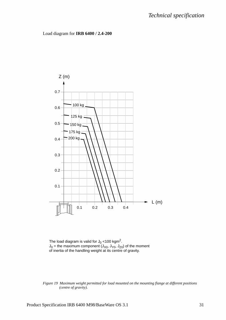
Load diagram for IRB 6400 / 2.4-200
Figure 19 Maximum weight permitted for load mounted on the mounting flange at different positions (centre of gravity).
0.1 0.2 0.3
0.1
0.2
0.3
0.4
0.5
0.6
0.7
0.4
Z (m)
L (m)
150 kg
125 kg
100 kg
200 kg
175 kg
The load diagram is valid for J0 <100 kgm2.J0 = the maximum component (JX0, JY0, JZ0) of the moment of inertia of the handling weight at its centre of gravity.
Product Specification IRB 6400 M98/BaseWare OS 3.1 31
Technical specification
3
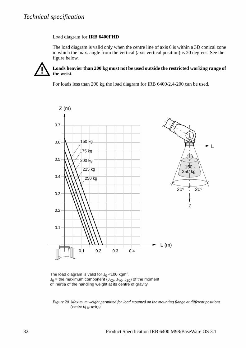
Load diagram for IRB 6400FHD
The load diagram is valid only when the centre line of axis 6 is within a 3D conical zone in which the max. angle from the vertical (axis vertical position) is 20 degrees. See the figure below.
Loads heavier than 200 kg must not be used outside the restricted working range of the wrist.
For loads less than 200 kg the load diagram for IRB 6400/2.4-200 can be used.
Figure 20 Maximum weight permitted for load mounted on the mounting flange at different positions (centre of gravity).
0.1 0.2 0.3
0.1
0.2
0.3
0.4
0.5
0.6
0.7
0.4
Z (m)
L (m)
150 kg
225 kg
250 kg
200 kg
175 kgL
250 kg
20o 20o
Z
150 -
The load diagram is valid for J0 <100 kgm2.J0 = the maximum component (JX0, JY0, JZ0) of the moment of inertia of the handling weight at its centre of gravity.
2 Product Specification IRB 6400 M98/BaseWare OS 3.1
Technical specification
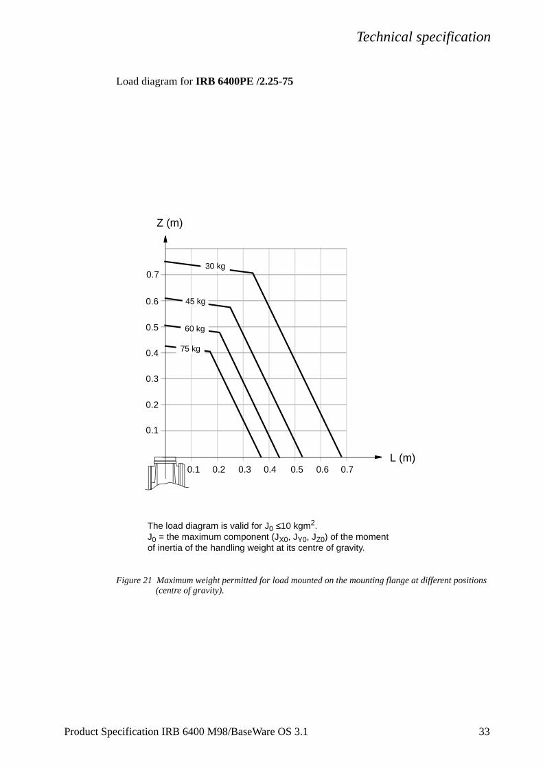
Load diagram for IRB 6400PE /2.25-75
Figure 21 Maximum weight permitted for load mounted on the mounting flange at different positions (centre of gravity).
0.1 0.2 0.3
0.1
0.2
0.3
0.4
0.5
0.6
0.7
0.4 0.5 0.6 0.7
Z (m)
L (m)
75 kg
30 kg
45 kg
60 kg
The load diagram is valid for J0 ≤10 kgm2.J0 = the maximum component (JX0, JY0, JZ0) of the moment of inertia of the handling weight at its centre of gravity.
Product Specification IRB 6400 M98/BaseWare OS 3.1 33
Technical specification
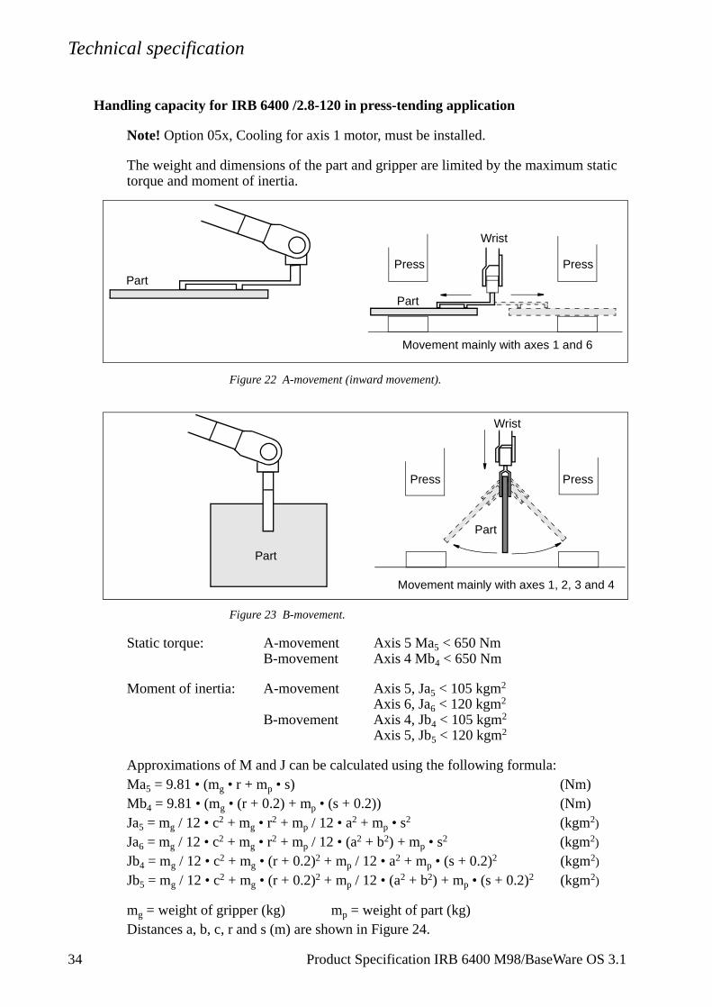
Handling capacity for IRB 6400 /2.8-120 in press-tending application
Note! Option 05x, Cooling for axis 1 motor, must be installed.
The weight and dimensions of the part and gripper are limited by the maximum static torque and moment of inertia.
Figure 22 A-movement (inward movement).
Figure 23 B-movement.
Static torque: A-movement Axis 5 Ma5 < 650 NmB-movement Axis 4 Mb4 < 650 Nm
Moment of inertia: A-movement Axis 5, Ja5 < 105 kgm2 Axis 6, Ja6 < 120 kgm2
B-movement Axis 4, Jb4 < 105 kgm2 Axis 5, Jb5 < 120 kgm2
Approximations of M and J can be calculated using the following formula:Ma5 = 9.81 • (mg • r + mp • s) (Nm)Mb4 = 9.81 • (mg • (r + 0.2) + mp • (s + 0.2)) (Nm)Ja5 = mg / 12 • c2 + mg • r2 + mp / 12 • a2 + mp • s2 (kgm2)
Ja6 = mg / 12 • c2 + mg • r2 + mp / 12 • (a2 + b2) + mp • s2 (kgm2)
Jb4 = mg / 12 • c2 + mg • (r + 0.2)2 + mp / 12 • a2 + mp • (s + 0.2)2 (kgm2)
Jb5 = mg / 12 • c2 + mg • (r + 0.2)2 + mp / 12 • (a2 + b2) + mp • (s + 0.2)2 (kgm2)
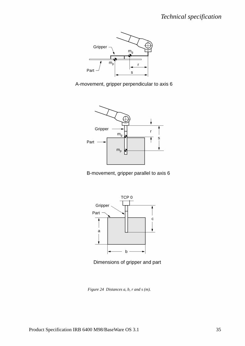
mg = weight of gripper (kg) mp = weight of part (kg)Distances a, b, c, r and s (m) are shown in Figure 24.
Press Press
Movement mainly with axes 1 and 6
Wrist
Part
Part
Press Press
Movement mainly with axes 1, 2, 3 and 4
Wrist
Part
Part
34 Product Specification IRB 6400 M98/BaseWare OS 3.1
Technical specification
Figure 24 Distances a, b, r and s (m).
Grippermg
r
s
mp
A-movement, gripper perpendicular to axis 6
B-movement, gripper parallel to axis 6
Gripper r
s
mp
mg
Dimensions of gripper and part
TCP 0
c
a
Gripper
b
Part
Part
Part
Product Specification IRB 6400 M98/BaseWare OS 3.1 35
Technical specification
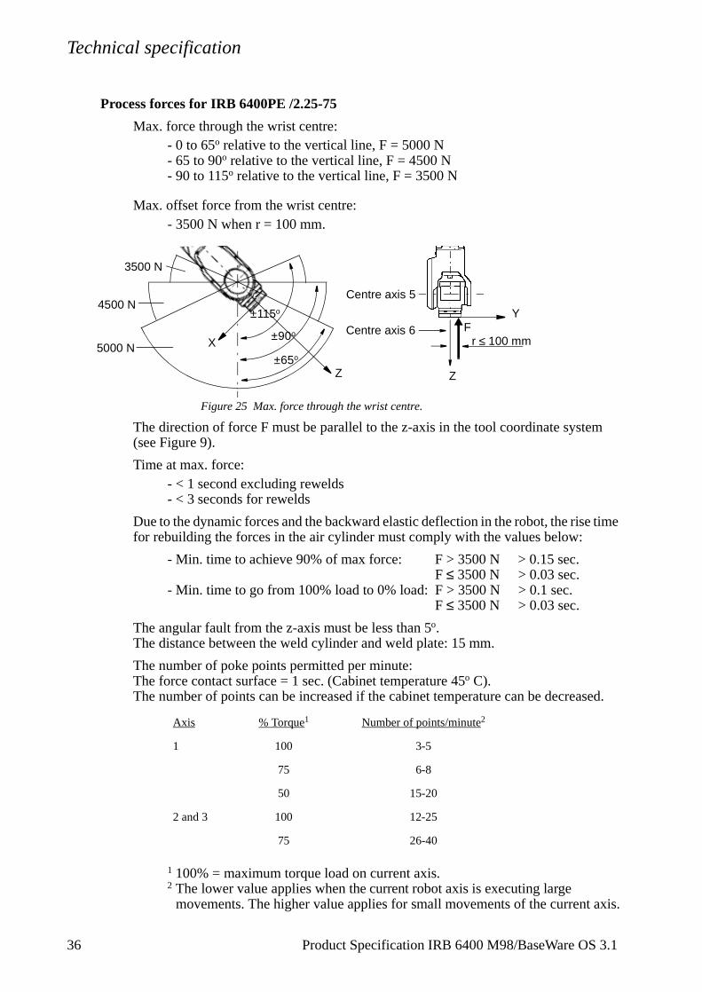
Process forces for IRB 6400PE /2.25-75
Max. force through the wrist centre:- 0 to 65o relative to the vertical line, F = 5000 N- 65 to 90o relative to the vertical line, F = 4500 N- 90 to 115o relative to the vertical line, F = 3500 N
Max. offset force from the wrist centre: - 3500 N when r = 100 mm.
Figure 25 Max. force through the wrist centre.
The direction of force F must be parallel to the z-axis in the tool coordinate system (see Figure 9).
Time at max. force:- < 1 second excluding rewelds- < 3 seconds for rewelds
Due to the dynamic forces and the backward elastic deflection in the robot, the rise time for rebuilding the forces in the air cylinder must comply with the values below:
- Min. time to achieve 90% of max force: F > 3500 N > 0.15 sec.F ≤ 3500 N > 0.03 sec.
- Min. time to go from 100% load to 0% load: F > 3500 N > 0.1 sec.F ≤ 3500 N > 0.03 sec.
The angular fault from the z-axis must be less than 5o.The distance between the weld cylinder and weld plate: 15 mm.
The number of poke points permitted per minute:The force contact surface = 1 sec. (Cabinet temperature 45o C).The number of points can be increased if the cabinet temperature can be decreased.
1 100% = maximum torque load on current axis.2 The lower value applies when the current robot axis is executing large
movements. The higher value applies for small movements of the current axis.
Axis % Torque1 Number of points/minute2
1 100 3-5
75 6-8
50 15-20
2 and 3 100 12-25
75 26-40
5000 N
4500 N
3500 N
±115o
±90o
±65o
Z
Fr ≤ 100 mm
Centre axis 6
Centre axis 5
Z
X
Y
36 Product Specification IRB 6400 M98/BaseWare OS 3.1
Technical specification
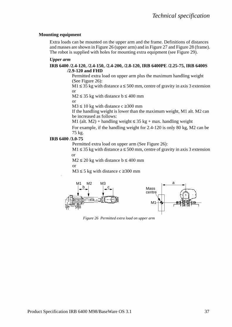
Mounting equipment
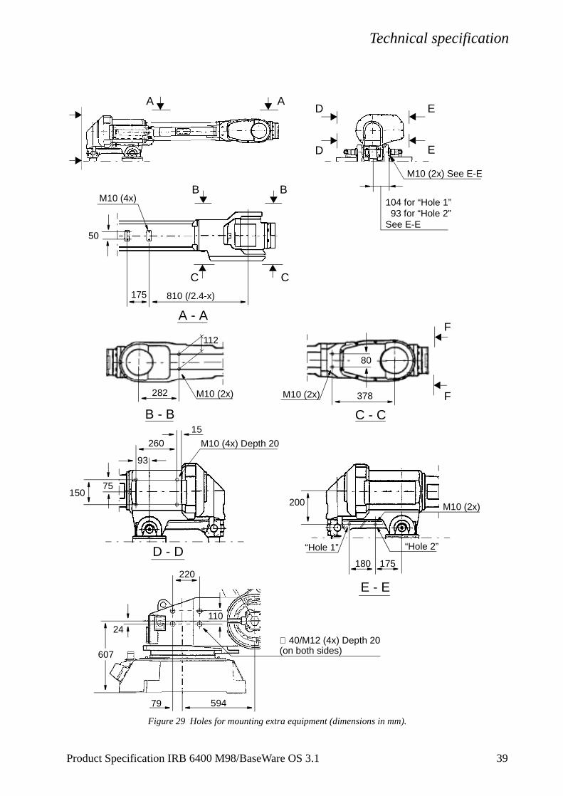
Extra loads can be mounted on the upper arm and the frame. Definitions of distances and masses are shown in Figure 26 (upper arm) and in Figure 27 and Figure 28 (frame).The robot is supplied with holes for mounting extra equipment (see Figure 29).
Upper armIRB 6400 /2.4-120, /2.4-150, /2.4-200, /2.8-120, IRB 6400PE /2.25-75, IRB 6400S
/2.9-120 and FHDPermitted extra load on upper arm plus the maximum handling weight (See Figure 26):M1 ≤ 35 kg with distance a ≤ 500 mm, centre of gravity in axis 3 extensionorM2 ≤ 35 kg with distance b ≤ 400 mmorM3 ≤ 10 kg with distance c ≥300 mmIf the handling weight is lower than the maximum weight, M1 alt. M2 can be increased as follows:M1 (alt. M2) + handling weight ≤ 35 kg + max. handling weightFor example, if the handling weight for 2.4-120 is only 80 kg, M2 can be 75 kg.
IRB 6400 /3.0-75Permitted extra load on upper arm (See Figure 26):M1 ≤ 35 kg with distance a ≤ 500 mm, centre of gravity in axis 3 extensionorM2 ≤ 20 kg with distance b ≤ 400 mmorM3 ≤ 5 kg with distance c ≥300 mm
/
Figure 26 Permitted extra load on upper arm
Masscentre
ab c
M1
M2 M3M1
Product Specification IRB 6400 M98/BaseWare OS 3.1 37
Technical specification
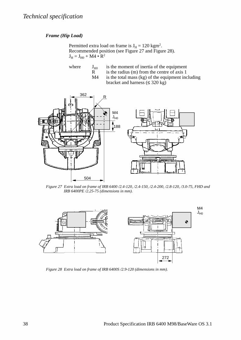
Frame (Hip Load)
Permitted extra load on frame is JH = 120 kgm2.Recommended position (see Figure 27 and Figure 28).JH = JH0 + M4 • R2
where JH0 is the moment of inertia of the equipmentR is the radius (m) from the centre of axis 1 M4 is the total mass (kg) of the equipment including
bracket and harness (≤ 320 kg)
Figure 27 Extra load on frame of IRB 6400 /2.4-120, /2.4-150, /2.4-200, /2.8-120, /3.0-75, FHD and IRB 6400PE /2.25-75 (dimensions in mm).
Figure 28 Extra load on frame of IRB 6400S /2.9-120 (dimensions in mm).
504
362 R
188
M4JH0
M4JH0
272
38 Product Specification IRB 6400 M98/BaseWare OS 3.1
Technical specification
Figure 29 Holes for mounting extra equipment (dimensions in mm).
A - A
AAD
D
B B
B - B
D - D
C C
E
E
E - E
175 810 (/2.4-x)
50
M10 (4x)
M10 (2x)282
93
260 M10 (4x) Depth 20
75150
200 M10 (2x)
175180
M10 (2x) See E-E
∅ 40/M12 (4x) Depth 20(on both sides)
59479
220
110
607
24
104 for “Hole 1”
C - C
80
M10 (2x) 378
F
F
93 for “Hole 2”See E-E
“Hole 1” “Hole 2”
112
15
Product Specification IRB 6400 M98/BaseWare OS 3.1 39
Technical specification
4
.
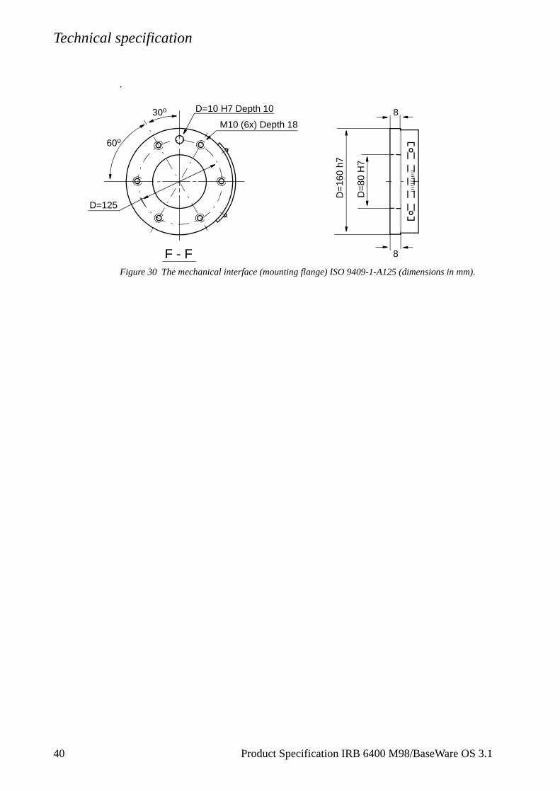
Figure 30 The mechanical interface (mounting flange) ISO 9409-1-A125 (dimensions in mm).
30o
60o
D=10 H7 Depth 10
M10 (6x) Depth 18
D=
160
h7
D=
80 H
7
D=125
8
8F - F
0 Product Specification IRB 6400 M98/BaseWare OS 3.1
Technical specification
3.5 Programming
The programming language - RAPID - is a high-level application-oriented programming language and includes the following functionality:
- hierarchial and modular structure
- functions and procedures
- global or local data and routines
- data typing, including structured and array types
- user defined names on variables, routines, inputs/outputs etc.
- extensive program flow control
- arithmetic and logical expressions
- interrupt handling
- error handling
- user defined instructions
- backward execution handler
The available sets of instructions/functions are given below. A subset of instructions to suit the needs of a particular installation, or the experience of the programmer, can be installed in pick lists. New instructions can easily be made by defining macros consisting of a sequence of standard instructions.
Note that the lists below only cover BaseWare OS. For instructions and functions associated with optional software, see Product Specification RobotWare.
Miscellaneous:= Assigns a valueWaitTime Waits a given amount of timeWaitUntil Waits until a condition is metcomment Inserts comments into the programOpMode Reads the current operating modeRunMode Reads the current program execution modeDim Gets the size of an arrayPresent Tests if an optional parameter is usedLoad Loads a program module during executionUnLoad Deletes a program module during execution
To control the program flowProcCall Calls a new procedureCallByVar Calls a procedure by a variableRETURN Finishes execution of a routineFOR Repeats a given number of timesGOTO Goes to (jumps to) a new instructionCompact IF IF a condition is met, THEN execute one instructionIF IF a condition is met, THEN execute a sequence of instructionslabel Line name (used together with GOTO) TEST Depending on the value of an expression ...
Product Specification IRB 6400 M98/BaseWare OS 3.1 41
Technical specification
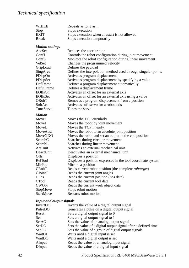
WHILE Repeats as long as ...Stop Stops executionEXIT Stops execution when a restart is not allowedBreak Stops execution temporarily
Motion settingsAccSet Reduces the accelerationConfJ Controls the robot configuration during joint movementConfL Monitors the robot configuration during linear movementVelSet Changes the programmed velocityGripLoad Defines the payloadSingArea Defines the interpolation method used through singular pointsPDispOn Activates program displacementPDispSet Activates program displacement by specifying a valueDefFrame Defines a program displacement automaticallyDefDFrame Defines a displacement frameEOffsOn Activates an offset for an external axisEOffsSet Activates an offset for an external axis using a valueORobT Removes a program displacement from a positionSoftAct Activates soft servo for a robot axisTuneServo Tunes the servo
MotionMoveC Moves the TCP circularlyMoveJ Moves the robot by joint movementMoveL Moves the TCP linearlyMoveAbsJ Moves the robot to an absolute joint positionMoveXDO Moves the robot and set an output in the end positionSearchC Searches during circular movementSearchL Searches during linear movementActUnit Activates an external mechanical unit DeactUnit Deactivates an external mechanical unitOffs Displaces a positionRelTool Displaces a position expressed in the tool coordinate systemMirPos Mirrors a positionCRobT Reads current robot position (the complete robtarget)CJointT Reads the current joint anglesCPos Reads the current position (pos data) CTool Reads the current tool dataCWObj Reads the current work object dataStopMove Stops robot motionStartMove Restarts robot motion
Input and output signalsInvertDO Inverts the value of a digital output signalPulseDO Generates a pulse on a digital output signalReset Sets a digital output signal to 0Set Sets a digital output signal to 1SetAO Sets the value of an analog output signalSetDO Sets the value of a digital output signal after a defined timeSetGO Sets the value of a group of digital output signalsWaitDI Waits until a digital input is setWaitDO Waits until a digital output is setAInput Reads the value of an analog input signalDInput Reads the value of a digital input signal
42 Product Specification IRB 6400 M98/BaseWare OS 3.1
Technical specification
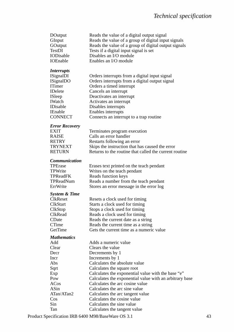
DOutput Reads the value of a digital output signalGInput Reads the value of a group of digital input signalsGOutput Reads the value of a group of digital output signalsTestDI Tests if a digital input signal is setIODisable Disables an I/O moduleIOEnable Enables an I/O module
InterruptsISignalDI Orders interrupts from a digital input signalISignalDO Orders interrupts from a digital output signalITimer Orders a timed interruptIDelete Cancels an interruptISleep Deactivates an interruptIWatch Activates an interruptIDisable Disables interruptsIEnable Enables interruptsCONNECT Connects an interrupt to a trap routine
Error RecoveryEXIT Terminates program executionRAISE Calls an error handler RETRY Restarts following an error TRYNEXT Skips the instruction that has caused the errorRETURN Returns to the routine that called the current routine
CommunicationTPErase Erases text printed on the teach pendantTPWrite Writes on the teach pendantTPReadFK Reads function keysTPReadNum Reads a number from the teach pendantErrWrite Stores an error message in the error log
System & TimeClkReset Resets a clock used for timingClkStart Starts a clock used for timingClkStop Stops a clock used for timingClkRead Reads a clock used for timingCDate Reads the current date as a stringCTime Reads the current time as a stringGetTime Gets the current time as a numeric value
MathematicsAdd Adds a numeric valueClear Clears the valueDecr Decrements by 1Incr Increments by 1Abs Calculates the absolute valueSqrt Calculates the square rootExp Calculates the exponential value with the base “e”Pow Calculates the exponential value with an arbitrary baseACos Calculates the arc cosine valueASin Calculates the arc sine valueATan/ATan2 Calculates the arc tangent valueCos Calculates the cosine valueSin Calculates the sine valueTan Calculates the tangent value
Product Specification IRB 6400 M98/BaseWare OS 3.1 43
Technical specification
a
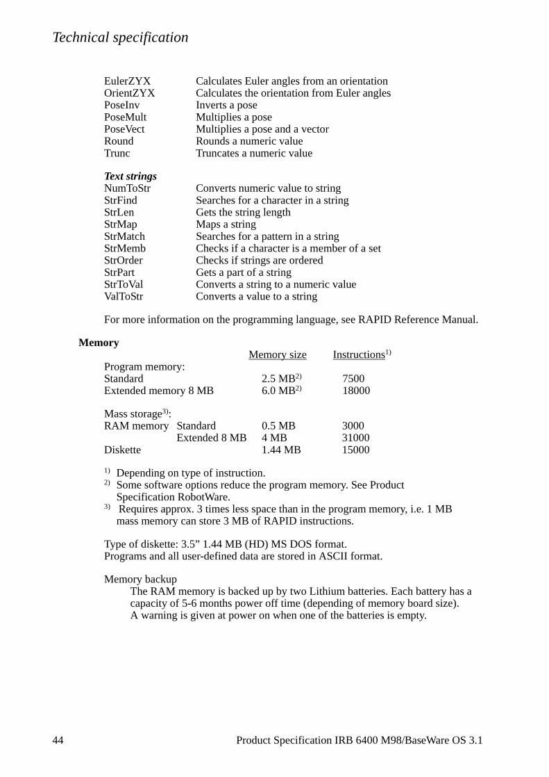
EulerZYX Calculates Euler angles from an orientationOrientZYX Calculates the orientation from Euler anglesPoseInv Inverts a posePoseMult Multiplies a posePoseVect Multiplies a pose and a vectorRound Rounds a numeric valueTrunc Truncates a numeric value
Text stringsNumToStr Converts numeric value to stringStrFind Searches for a character in a stringStrLen Gets the string lengthStrMap Maps a stringStrMatch Searches for a pattern in a stringStrMemb Checks if a character is a member of a setStrOrder Checks if strings are orderedStrPart Gets a part of a stringStrToVal Converts a string to a numeric valueValToStr Converts a value to a string
For more information on the programming language, see RAPID Reference Manual.
MemoryMemory size Instructions1)
Program memory:Standard 2.5 MB2) 7500 Extended memory 8 MB 6.0 MB2) 18000
Mass storage3):RAM memory Standard 0.5 MB 3000
Extended 8 MB 4 MB 31000Diskette 1.44 MB 15000
1) Depending on type of instruction.2) Some software options reduce the program memory. See Product
Specification RobotWare.3) Requires approx. 3 times less space than in the program memory, i.e. 1 MB
mass memory can store 3 MB of RAPID instructions.
Type of diskette: 3.5” 1.44 MB (HD) MS DOS format.Programs and all user-defined data are stored in ASCII format.
Memory backupThe RAM memory is backed up by two Lithium batteries. Each battery hascapacity of 5-6 months power off time (depending of memory board size).A warning is given at power on when one of the batteries is empty.
44 Product Specification IRB 6400 M98/BaseWare OS 3.1
Technical specification
3.6 Automatic Operation
The following production window commands are available:
- Load/select the program.
- Start the program.
- Execute instruction-by-instruction (forward/backward).
- Reduce the velocity temporarily.
- Display program-controlled comments (which tell the operator what is happening).
- Displace a position, also during program execution (can be blocked).
3.7 Maintenance and Troubleshooting
The following maintenance is required:
- Changing filter for the transformer/drive unit cooling every year.
- Changing grease and oil every third year.
- Changing batteries every third year.
- Some additional checks every year.
The maintenance intervals depends on the use of the robot. For detailed information on maintenance procedures, see Maintenance section in the Product Manual.
Product Specification IRB 6400 M98/BaseWare OS 3.1 45
Technical specification
4
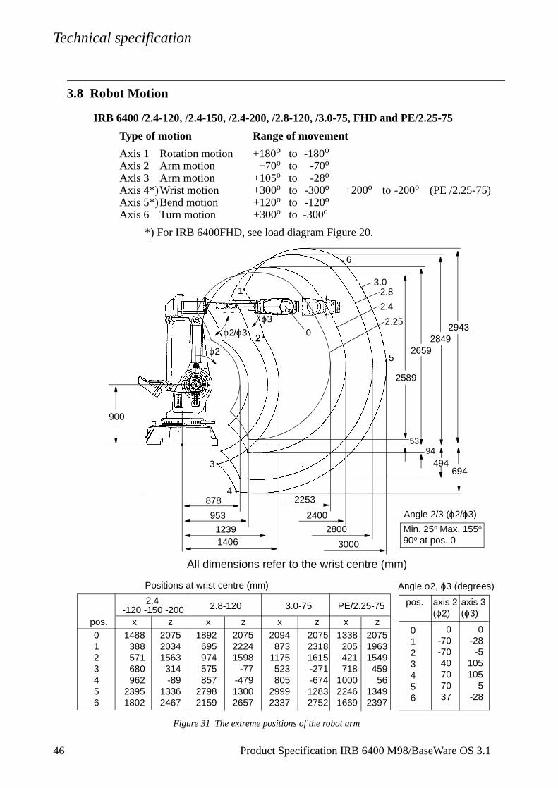
6 Product Specification IRB 6400 M98/BaseWare OS 3.13.8 Robot Motion
IRB 6400 /2.4-120, /2.4-150, /2.4-200, /2.8-120, /3.0-75, FHD and PE/2.25-75
Type of motion Range of movement
Axis 1 Rotation motion +180o to -180o Axis 2 Arm motion +70o to -70o Axis 3 Arm motion +105o to -28o Axis 4*)Wrist motion +300o to -300o +200o to -200o (PE /2.25-75)Axis 5*)Bend motion +120o to -120o Axis 6 Turn motion +300o to -300o
*) For IRB 6400FHD, see load diagram Figure 20.
Figure 31 The extreme positions of the robot arm
1338205421718
100022461669
20751963154945956
13492397
pos. axis 2 (ϕ2)
axis 3 (ϕ3)
0123456
0-70-7040707037
0-28-5
105105
5-28
Min. 25o Max. 155o 90o at pos. 0
1488388571680962
23951802
207520341563
314-89
13362467
1892695974575857
27982159
207522241598
-77-47913002657
2094873
1175523805
29992337
207523181615-271-67412832752
0123456
Positions at wrist centre (mm)
pos.
2.4 3.0-752.8-120
xz z zx x
Angle ϕ2, ϕ3 (degrees)
Angle 2/3 (ϕ2/ϕ3)
PE/2.25-75
zx
26592849
2943
2.4
2.83.0
94
494694
953
12391406
2400
2800
3000
All dimensions refer to the wrist centre (mm)
878 2253
53
2589
2.25
900
1
6
2
3
4
5ϕ2
ϕ3ϕ2/ϕ3
-120 -150 -200
20
Technical specification
Product Specification IRB 6400 M98/BaseWare OS 3.1 47
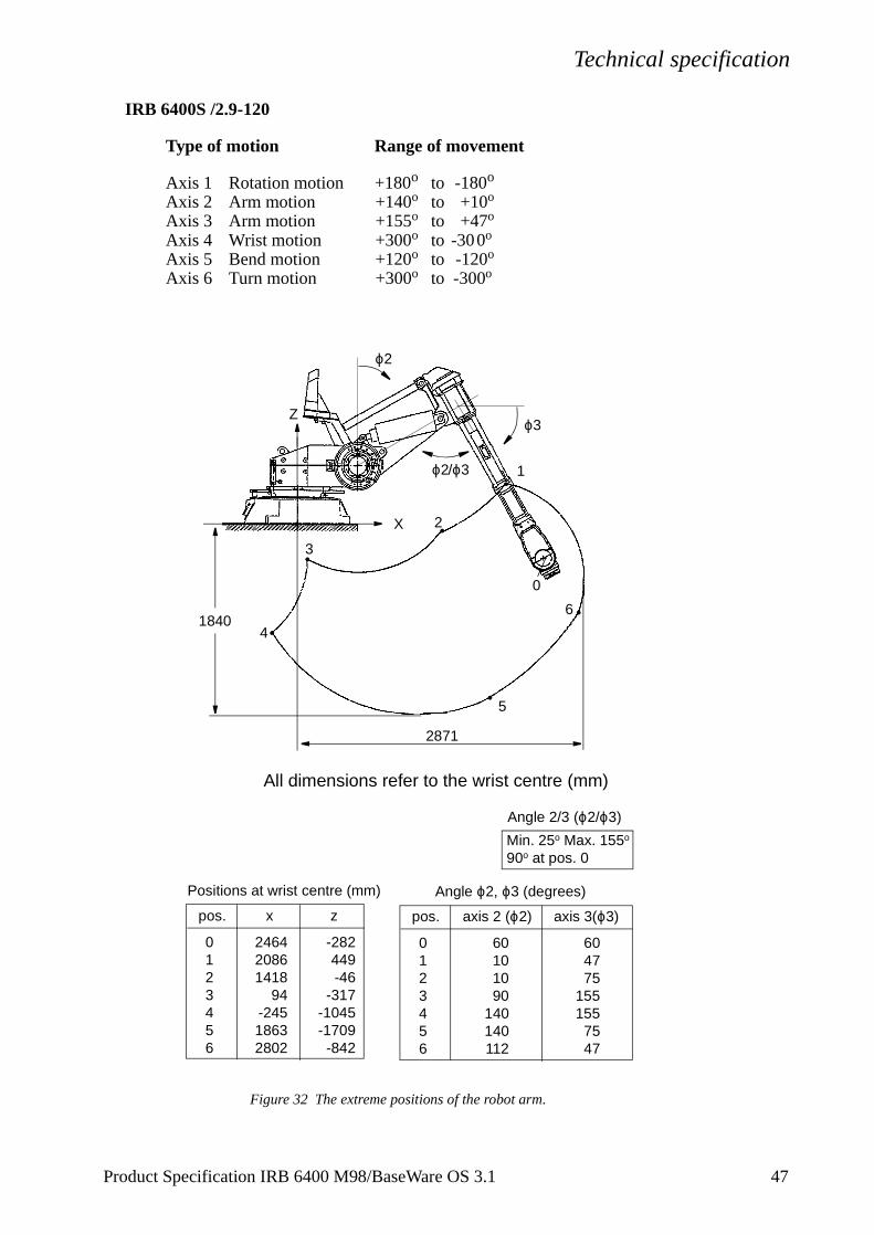
IRB 6400S /2.9-120
Type of motion Range of movement
Axis 1 Rotation motion +180o to -180o Axis 2 Arm motion +140o to +10o Axis 3 Arm motion +155o to +47o Axis 4 Wrist motion +300o to -30 0o Axis 5 Bend motion +120o to -120o Axis 6 Turn motion +300o to -300o
Figure 32 The extreme positions of the robot arm.
pos. axis 2 (ϕ2) axis 3(ϕ3)
0123456
60101090
140140112
604775
155155
7547
Min. 25o Max. 155o 90o at pos. 0
Angle ϕ2, ϕ3 (degrees)
Angle 2/3 (ϕ2/ϕ3)
pos. x
0123456
246420861418
94-24518632802
Positions at wrist centre (mm)
z
-282449-46
-317-1045-1709-842
All dimensions refer to the wrist centre (mm)
1
2
3
4
5
6
0
2871
1840
ϕ2
ϕ3Z
X
ϕ2/ϕ3

Technical specification
4
Performance according to ISO 9283
At rated load and 1 m/s velocity on the inclined ISO test plane with all six robot axes in motion.
Unidirectional pose repeatability: RP = 0.1 mm (IRB 6400/2.4-120)RP = 0.15 mm (IRB 6400/2.4-150 and IRB 6400/2.4-200)RP = 0.2 mm (Others)
Linear path accuracy: AT = 2.1 - 2.5 mm (IRB 6400/2.4-120)AT = 2.5 - 3.0 mm (Others)
Linear path repeatability:RT = 0.5 - 0.8 mm (IRB 6400/2.4-120)RT = 0.8 - 1.4 mm (Others)
Minimum positioning time, to within 0.4 mm of the position:0.2 - 0.3 sec. (IRB 6400/2.4-120, on 35 mm linear path)0.6 - 0.8 sec. (IRB 6400/2.4-120, on 350 mm linear path)0.3 - 0.5 sec. (Others, on 35 mm linear path)0.7 - 0.9 sec. (Others, on 350 mm linear path)
The above values are the range of average test-results from a number of robots. If guaranteed values are required, please contact your nearest ABB Flexible Automation Centre.
Velocity IRB 6400 versions:2.4-120 2.4-150 2.8-120 3.0-75 S/2.9-120 PE/2.25-75
2.4-200C/ B-150FHD
Axis no.
1 100o/s 90o/s 100o/s 100o/s 100o/s 70o/s2 100o/s 90o/s 100o/s 100o/s 100o/s 70o/s3 100o/s 90o/s 100o/s 100o/s 100o/s 70o/s4 210o/s 120o/s 210o/s 210o/s 210o/s 210o/s5 150o/s 120o/s 150o/s 150o/s 150o/s 150o/s6 210o/s 190o/s 210o/s 210o/s 210o/s 210o/s
There is a supervision function to prevent overheating in applications with intensive and frequent movements.
ResolutionApprox. 0.01o on each axis.
8 Product Specification IRB 6400 M98/BaseWare OS 3.1
Technical specification
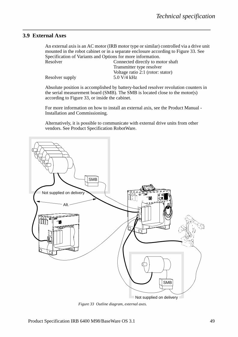
3.9 External Axes
An external axis is an AC motor (IRB motor type or similar) controlled via a drive unit mounted in the robot cabinet or in a separate enclosure according to Figure 33. See Specification of Variants and Options for more information.Resolver Connected directly to motor shaft
Transmitter type resolver Voltage ratio 2:1 (rotor: stator)
Resolver supply 5.0 V/4 kHz
Absolute position is accomplished by battery-backed resolver revolution counters in the serial measurement board (SMB). The SMB is located close to the motor(s) according to Figure 33, or inside the cabinet.
For more information on how to install an external axis, see the Product Manual - Installation and Commissioning.
Alternatively, it is possible to communicate with external drive units from other vendors. See Product Specification RobotWare.
Figure 33 Outline diagram, external axes.
Not supplied on delivery
Alt.
Not supplied on delivery
SMB
SMB
Product Specification IRB 6400 M98/BaseWare OS 3.1 49
Technical specification
5
of
nd
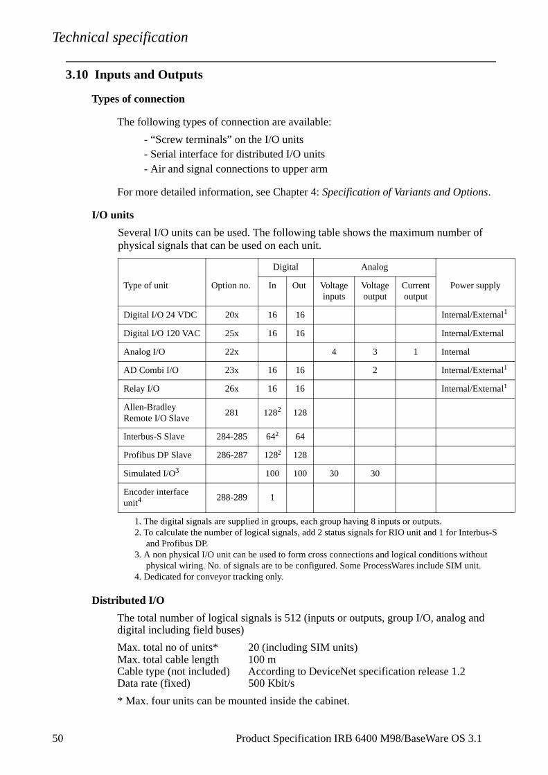
3.10 Inputs and Outputs
Types of connection
The following types of connection are available:
- “Screw terminals” on the I/O units- Serial interface for distributed I/O units- Air and signal connections to upper arm
For more detailed information, see Chapter 4: Specification of Variants and Options.
I/O units
Several I/O units can be used. The following table shows the maximum numberphysical signals that can be used on each unit.
Distributed I/O
The total number of logical signals is 512 (inputs or outputs, group I/O, analog adigital including field buses)
Max. total no of units* 20 (including SIM units)Max. total cable length 100 mCable type (not included) According to DeviceNet specification release 1.2Data rate (fixed) 500 Kbit/s
* Max. four units can be mounted inside the cabinet.
Type of unit Option no.
Digital Analog
Power supplyIn Out Voltageinputs
Voltage output
Current output
Digital I/O 24 VDC 20x 16 16 Internal/External1
1. The digital signals are supplied in groups, each group having 8 inputs or outputs.
Digital I/O 120 VAC 25x 16 16 Internal/External
Analog I/O 22x 4 3 1 Internal
AD Combi I/O 23x 16 16 2 Internal/External1
Relay I/O 26x 16 16 Internal/External1
Allen-Bradley Remote I/O Slave
281 1282
2. To calculate the number of logical signals, add 2 status signals for RIO unit and 1 for Interbus-S and Profibus DP.
128
Interbus-S Slave 284-285 642 64
Profibus DP Slave 286-287 1282 128
Simulated I/O3
3. A non physical I/O unit can be used to form cross connections and logical conditions without physical wiring. No. of signals are to be configured. Some ProcessWares include SIM unit.
100 100 30 30
Encoder interface unit4
4. Dedicated for conveyor tracking only.
288-289 1
0 Product Specification IRB 6400 M98/BaseWare OS 3.1
Technical specification
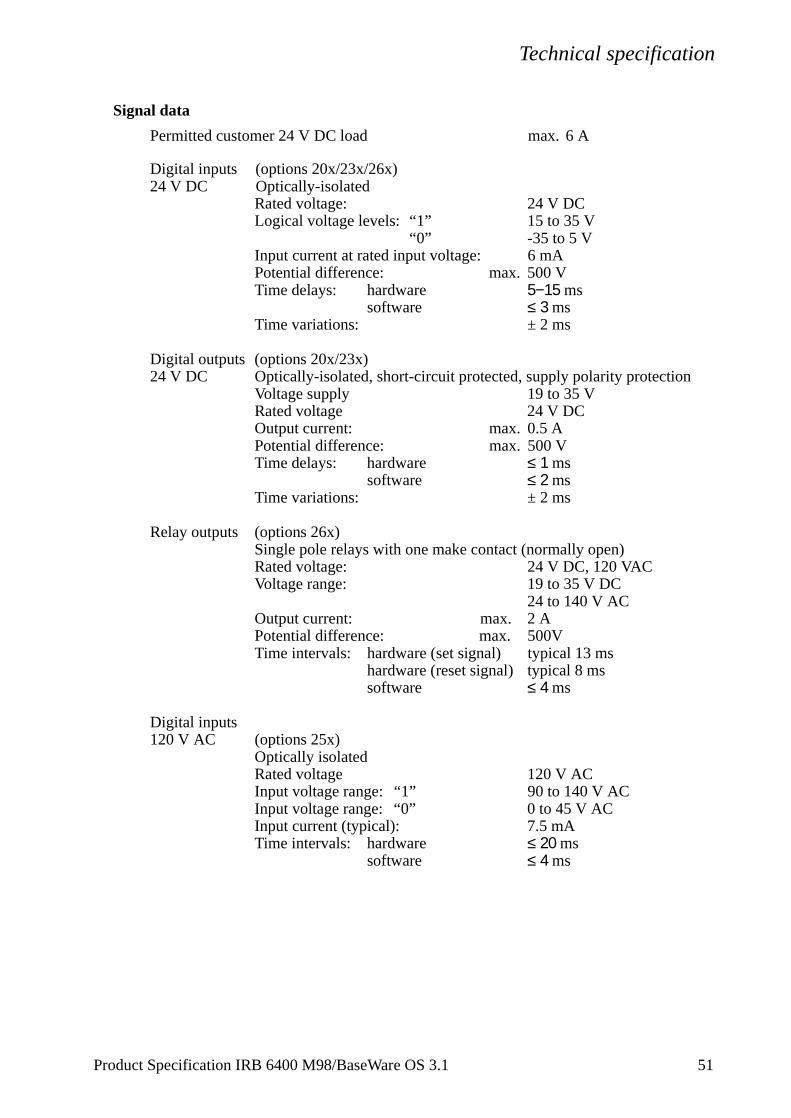
Signal data
Permitted customer 24 V DC load max. 6 A
Digital inputs (options 20x/23x/26x)24 V DC Optically-isolated
Rated voltage: 24 V DCLogical voltage levels: “1” 15 to 35 V
“0” -35 to 5 VInput current at rated input voltage: 6 mAPotential difference: max. 500 VTime delays: hardware 5−15 ms
software ≤ 3 msTime variations: ± 2 ms
Digital outputs (options 20x/23x)24 V DC Optically-isolated, short-circuit protected, supply polarity protection
Voltage supply 19 to 35 VRated voltage 24 V DCOutput current: max. 0.5 APotential difference: max. 500 VTime delays: hardware ≤ 1 ms
software ≤ 2 msTime variations: ± 2 ms
Relay outputs (options 26x)Single pole relays with one make contact (normally open)Rated voltage: 24 V DC, 120 VACVoltage range: 19 to 35 V DC
24 to 140 V ACOutput current: max. 2 APotential difference: max. 500VTime intervals: hardware (set signal) typical 13 ms
hardware (reset signal) typical 8 mssoftware ≤ 4 ms
Digital inputs120 V AC (options 25x)
Optically isolatedRated voltage 120 V ACInput voltage range: “1” 90 to 140 V ACInput voltage range: “0” 0 to 45 V ACInput current (typical): 7.5 mATime intervals: hardware ≤ 20 ms
software ≤ 4 ms
Product Specification IRB 6400 M98/BaseWare OS 3.1 51
Technical specification
5
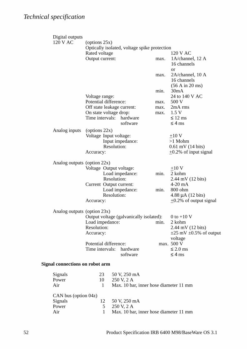
Digital outputs 120 V AC (options 25x)
Optically isolated, voltage spike protectionRated voltage 120 V ACOutput current: max. 1A/channel, 12 A
16 channelsor
max. 2A/channel, 10 A 16 channels(56 A in 20 ms)
min. 30mAVoltage range: 24 to 140 V ACPotential difference: max. 500 VOff state leakage current: max. 2mA rmsOn state voltage drop: max. 1.5 VTime intervals: hardware ≤ 12 ms
software ≤ 4 ms
Analog inputs (options 22x)Voltage Input voltage: +10 V
Input impedance: >1 MohmResolution: 0.61 mV (14 bits)
Accuracy: +0.2% of input signal
Analog outputs (option 22x)Voltage Output voltage: +10 V
Load impedance: min. 2 kohmResolution: 2.44 mV (12 bits)
Current Output current: 4-20 mALoad impedance: min. 800 ohmResolution: 4.88 µA (12 bits)
Accuracy: +0.2% of output signal
Analog outputs (option 23x)Output voltage (galvanically isolated): 0 to +10 V Load impedance: min. 2 kohmResolution: 2.44 mV (12 bits)Accuracy: ±25 mV ±0.5% of output
voltagePotential difference: max. 500 VTime intervals: hardware ≤ 2.0 ms
software ≤ 4 ms
Signal connections on robot arm
Signals 23 50 V, 250 mAPower 10 250 V, 2 AAir 1 Max. 10 bar, inner hose diameter 11 mm
CAN bus (option 04z)Signals 12 50 V, 250 mAPower 5 250 V, 2 AAir 1 Max. 10 bar, inner hose diameter 11 mm
2 Product Specification IRB 6400 M98/BaseWare OS 3.1
Technical specification
.
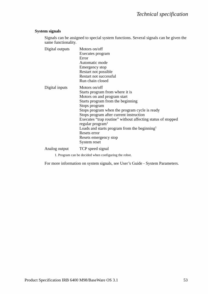
System signals
Signals can be assigned to special system functions. Several signals can be given the same functionality.
Digital outputs Motors on/offExecutes program ErrorAutomatic modeEmergency stopRestart not possibleRestart not successfulRun chain closed
Digital inputs Motors on/offStarts program from where it isMotors on and program startStarts program from the beginningStops programStops program when the program cycle is readyStops program after current instructionExecutes “trap routine” without affecting status of stoppedregular program1 Loads and starts program from the beginning1
Resets errorResets emergency stopSystem reset
Analog output TCP speed signal
1. Program can be decided when configuring the robot.
For more information on system signals, see User’s Guide - System Parameters
Product Specification IRB 6400 M98/BaseWare OS 3.1 53
Technical specification
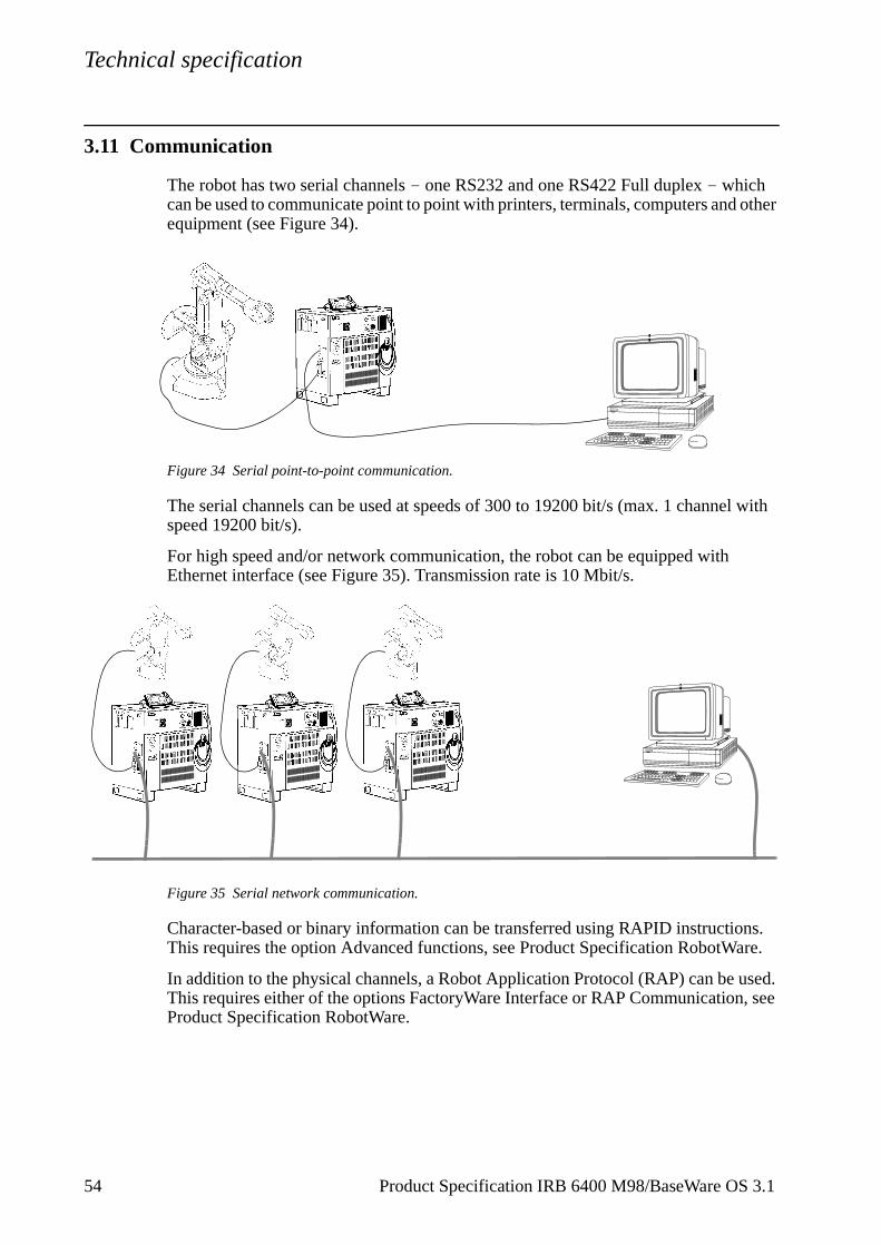
3.11 Communication
The robot has two serial channels - one RS232 and one RS422 Full duplex - which can be used to communicate point to point with printers, terminals, computers and other equipment (see Figure 34).
Figure 34 Serial point-to-point communication.
The serial channels can be used at speeds of 300 to 19200 bit/s (max. 1 channel with speed 19200 bit/s).
For high speed and/or network communication, the robot can be equipped with Ethernet interface (see Figure 35). Transmission rate is 10 Mbit/s.
Figure 35 Serial network communication.
Character-based or binary information can be transferred using RAPID instructions. This requires the option Advanced functions, see Product Specification RobotWare.
In addition to the physical channels, a Robot Application Protocol (RAP) can be used. This requires either of the options FactoryWare Interface or RAP Communication, see Product Specification RobotWare.
54 Product Specification IRB 6400 M98/BaseWare OS 3.1
Specification of Variants and Options
d into and
4 Specification of Variants and Options
The different variants and options for the IRB 6400 are described below.The same numbers are used here as in the Specification form. For software options, see Product Specification RobotWare.
Note Options marked with * are inconsistent with UL/UR approval.
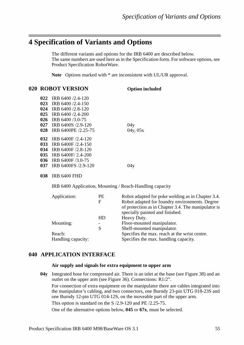
020 ROBOT VERSION Option included
022 IRB 6400 /2.4-120023 IRB 6400 /2.4-150024 IRB 6400 /2.8-120025 IRB 6400 /2.4-200026 IRB 6400 /3.0-75027 IRB 6400S /2.9-120 04y028 IRB 6400PE /2.25-75 04y, 05x
032 IRB 6400F /2.4-120033 IRB 6400F /2.4-150034 IRB 6400F /2.8-120035 IRB 6400F/ 2.4-200036 IRB 6400F /3.0-75037 IRB 6400FS /2.9-120 04y
038 IRB 6400 FHD
IRB 6400 Application, Mounting / Reach-Handling capacity
Application: PE Robot adapted for poke welding as in Chapter 3.4. F Robot adapted for foundry environments. Degree
of protection as in Chapter 3.4. The manipulator is specially painted and finished.
HD Heavy Duty.Mounting: - Floor-mounted manipulator.
S Shelf-mounted manipulator.Reach: Specifies the max. reach at the wrist centre.Handling capacity: Specifies the max. handling capacity.
040 APPLICATION INTERFACE
Air supply and signals for extra equipment to upper arm
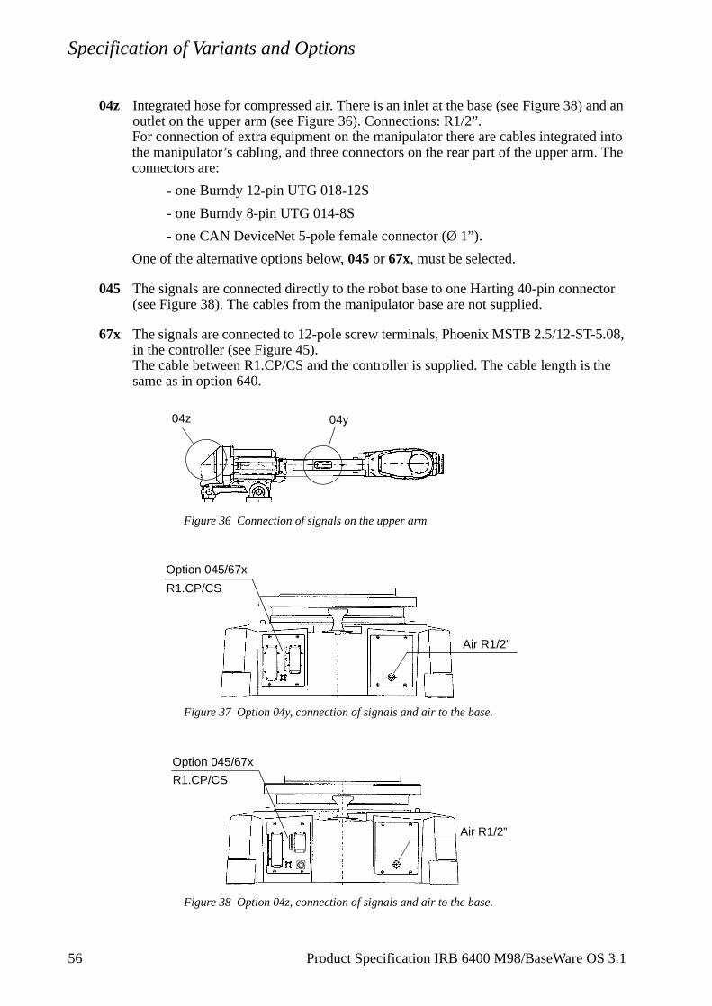
04y Integrated hose for compressed air. There is an inlet at the base (see Figure 38) and an outlet on the upper arm (see Figure 36). Connections: R1/2”.For connection of extra equipment on the manipulator there are cables integratethe manipulator’s cabling, and two connectors, one Burndy 23-pin UTG 018-23Sone Burndy 12-pin UTG 014-12S, on the moveable part of the upper arm.This option is standard on the S /2.9-120 and PE /2.25-75. One of the alternative options below, 045 or 67x, must be selected.
Product Specification IRB 6400 M98/BaseWare OS 3.1 55
Specification of Variants and Options
d into . The
ctor
5.08,
the
04z Integrated hose for compressed air. There is an inlet at the base (see Figure 38) and an outlet on the upper arm (see Figure 36). Connections: R1/2”.For connection of extra equipment on the manipulator there are cables integratethe manipulator’s cabling, and three connectors on the rear part of the upper armconnectors are:
- one Burndy 12-pin UTG 018-12S
- one Burndy 8-pin UTG 014-8S
- one CAN DeviceNet 5-pole female connector (Ø 1”).
One of the alternative options below, 045 or 67x, must be selected.
045 The signals are connected directly to the robot base to one Harting 40-pin conne(see Figure 38). The cables from the manipulator base are not supplied.
67x The signals are connected to 12-pole screw terminals, Phoenix MSTB 2.5/12-ST-in the controller (see Figure 45).The cable between R1.CP/CS and the controller is supplied. The cable length issame as in option 640.
Figure 36 Connection of signals on the upper arm
Figure 37 Option 04y, connection of signals and air to the base.
Figure 38 Option 04z, connection of signals and air to the base.
04y04z
Option 045/67x
Air R1/2”
R1.CP/CS
Option 045/67x
Air R1/2”
R1.CP/CS
56 Product Specification IRB 6400 M98/BaseWare OS 3.1
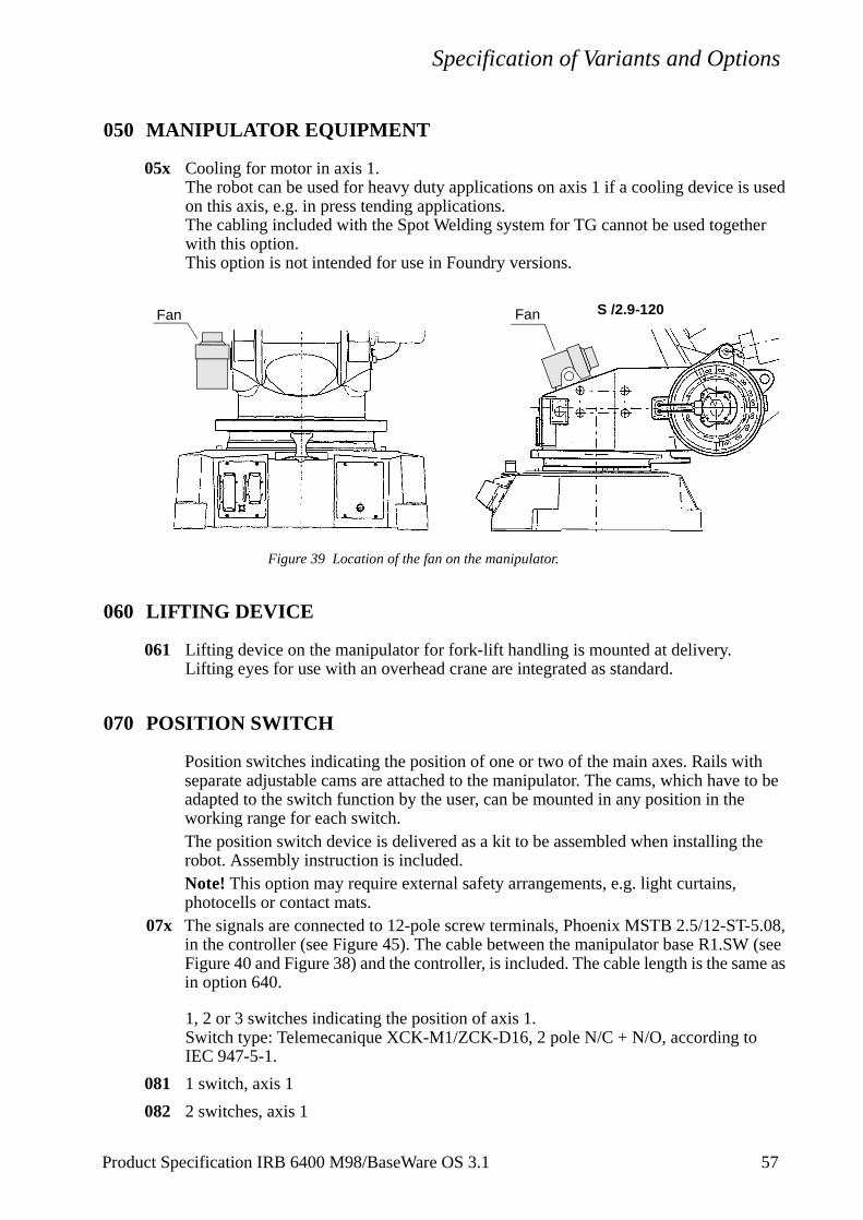
Specification of Variants and Options
050 MANIPULATOR EQUIPMENT
05x Cooling for motor in axis 1.The robot can be used for heavy duty applications on axis 1 if a cooling device is used on this axis, e.g. in press tending applications.The cabling included with the Spot Welding system for TG cannot be used together with this option.This option is not intended for use in Foundry versions.
Figure 39 Location of the fan on the manipulator.
060 LIFTING DEVICE
061 Lifting device on the manipulator for fork-lift handling is mounted at delivery.Lifting eyes for use with an overhead crane are integrated as standard.
070 POSITION SWITCH
Position switches indicating the position of one or two of the main axes. Rails with separate adjustable cams are attached to the manipulator. The cams, which have to be adapted to the switch function by the user, can be mounted in any position in the working range for each switch.The position switch device is delivered as a kit to be assembled when installing the robot. Assembly instruction is included.Note! This option may require external safety arrangements, e.g. light curtains, photocells or contact mats.
07x The signals are connected to 12-pole screw terminals, Phoenix MSTB 2.5/12-ST-5.08, in the controller (see Figure 45). The cable between the manipulator base R1.SW (see Figure 40 and Figure 38) and the controller, is included. The cable length is the same as in option 640.
1, 2 or 3 switches indicating the position of axis 1.Switch type: Telemecanique XCK-M1/ZCK-D16, 2 pole N/C + N/O, according to IEC 947-5-1.
081 1 switch, axis 1
082 2 switches, axis 1
S /2.9-120FanFan
Product Specification IRB 6400 M98/BaseWare OS 3.1 57
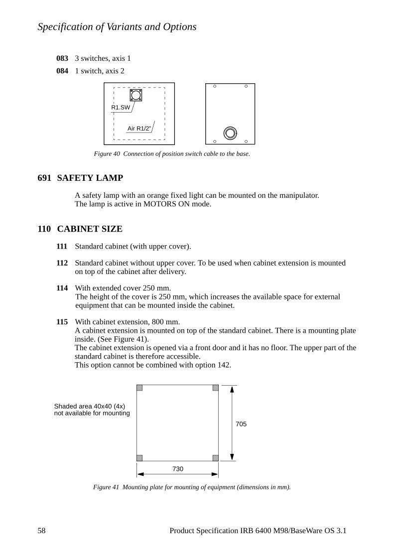
Specification of Variants and Options
083 3 switches, axis 1
084 1 switch, axis 2
Figure 40 Connection of position switch cable to the base.
691 SAFETY LAMP
A safety lamp with an orange fixed light can be mounted on the manipulator.The lamp is active in MOTORS ON mode.
110 CABINET SIZE
111 Standard cabinet (with upper cover).
112 Standard cabinet without upper cover. To be used when cabinet extension is mounted on top of the cabinet after delivery.
114 With extended cover 250 mm.The height of the cover is 250 mm, which increases the available space for external equipment that can be mounted inside the cabinet.
115 With cabinet extension, 800 mm.A cabinet extension is mounted on top of the standard cabinet. There is a mounting plate inside. (See Figure 41).The cabinet extension is opened via a front door and it has no floor. The upper part of the standard cabinet is therefore accessible.This option cannot be combined with option 142.
Figure 41 Mounting plate for mounting of equipment (dimensions in mm).
Air R1/2”
R1.SW
Shaded area 40x40 (4x)not available for mounting
705
730
58 Product Specification IRB 6400 M98/BaseWare OS 3.1
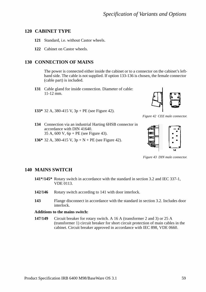
Specification of Variants and Options
t’s left-ector
,
he
120 CABINET TYPE
121 Standard, i.e. without Castor wheels.
122 Cabinet on Castor wheels.
130 CONNECTION OF MAINS
The power is connected either inside the cabinet or to a connector on the cabinehand side. The cable is not supplied. If option 133-136 is chosen, the female conn(cable part) is included.
131 Cable gland for inside connection. Diameter of cable: 11-12 mm.
133* 32 A, 380-415 V, 3p + PE (see Figure 42).Figure 42 CEE male connector.
134 Connection via an industrial Harting 6HSB connector in accordance with DIN 41640.35 A, 600 V, 6p + PE (see Figure 43).
136* 32 A, 380-415 V, 3p + N + PE (see Figure 42).
Figure 43 DIN male connector.
140 MAINS SWITCH
141*/145* Rotary switch in accordance with the standard in section 3.2 and IEC 337-1VDE 0113.
142/146 Rotary switch according to 141 with door interlock.
143 Flange disconnect in accordance with the standard in section 3.2. Includes door interlock.
Additions to the mains switch:
147/149 Circuit breaker for rotary switch. A 16 A (transformer 2 and 3) or 25 A (transformer 1) circuit breaker for short circuit protection of main cables in tcabinet. Circuit breaker approved in accordance with IEC 898, VDE 0660.
Product Specification IRB 6400 M98/BaseWare OS 3.1 59
Specification of Variants and Options
60 Product Specification IRB 6400 M98/BaseWare OS 3.1
150 MAINS VOLTAGEThe robot can be connected to a rated voltage of between 200 V and 600 V, 3-phase and protective earthing. A voltage fluctuation of +10% to -15% is permissible in each connection.
151- Transformer 1 Transformer 2 Transformer 3
174 200 V220 V400 V 400 V440 V 440 V
475 V 475 V500 V 500 V
525 V600 V
175 MAINS FILTER
The mains filter reduces the emission of radio frequency on the incoming power, to levels below requirements in the Machinery Directive 89/392/EEC. For installations in countries not affected by this directive, the filter can be excluded.
177-179 Mains filter
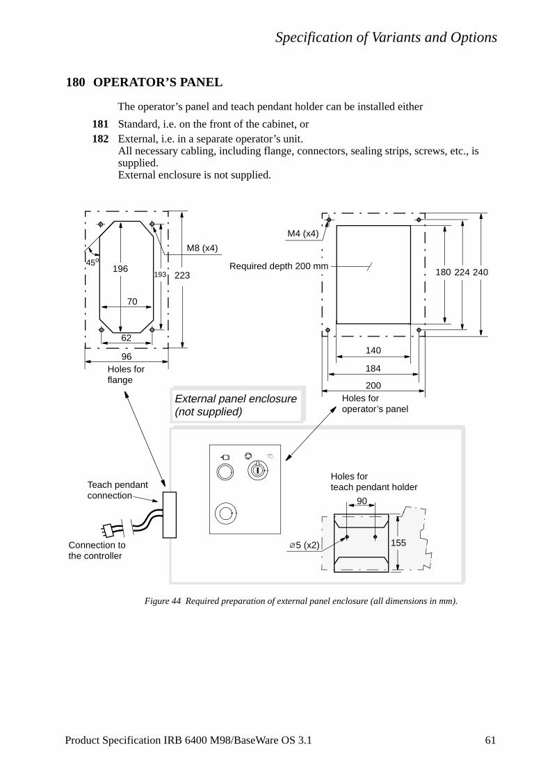
Specification of Variants and Options
s
180 OPERATOR’S PANEL
The operator’s panel and teach pendant holder can be installed either
181 Standard, i.e. on the front of the cabinet, or182 External, i.e. in a separate operator’s unit.
All necessary cabling, including flange, connectors, sealing strips, screws, etc., isupplied. External enclosure is not supplied.
Figure 44 Required preparation of external panel enclosure (all dimensions in mm).
184
224180
140
193196
70
62
45o
External panel enclosure(not supplied)
M8 (x4)
Connection to
Holes for flange
Holes for operator’s panel
Holes forteach pendant holder
the controller
90
1555 (x2)
Teach pendantconnection
200
240Required depth 200 mm
M4 (x4)
96
223
Product Specification IRB 6400 M98/BaseWare OS 3.1 61
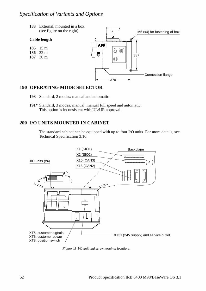
Specification of Variants and Options
183 External, mounted in a box, (see figure on the right).
Cable length
185 15 m186 22 m187 30 m
190 OPERATING MODE SELECTOR
193 Standard, 2 modes: manual and automatic
191* Standard, 3 modes: manual, manual full speed and automatic.This option is inconsistent with UL/UR approval.
200 I/O UNITS MOUNTED IN CABINET
The standard cabinet can be equipped with up to four I/O units. For more details, see Technical Specification 3.10.
Figure 45 I/O unit and screw terminal locations.
337
370
M5 (x4) for fastening of box
Connection flange
XT5, customer signalsXT6, customer powerXT8, position switch
I/O units (x4)
XT31 (24V supply) and service outlet
Backplane
X10 (CAN3)
X16 (CAN2)
X1 (SIO1)
X2 (SIO2)
62 Product Specification IRB 6400 M98/BaseWare OS 3.1
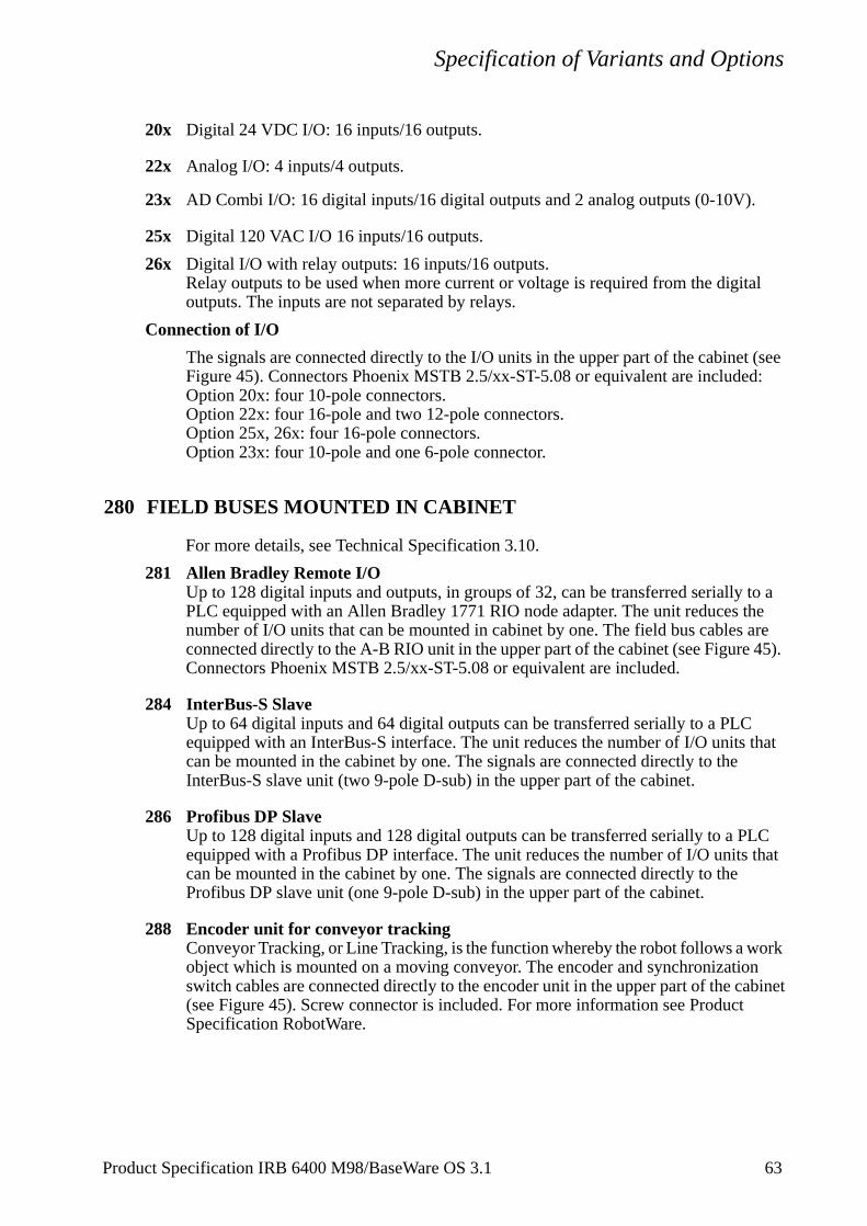
Specification of Variants and Options
20x Digital 24 VDC I/O: 16 inputs/16 outputs.
22x Analog I/O: 4 inputs/4 outputs.
23x AD Combi I/O: 16 digital inputs/16 digital outputs and 2 analog outputs (0-10V).
25x Digital 120 VAC I/O 16 inputs/16 outputs.
26x Digital I/O with relay outputs: 16 inputs/16 outputs. Relay outputs to be used when more current or voltage is required from the digital outputs. The inputs are not separated by relays.
Connection of I/O
The signals are connected directly to the I/O units in the upper part of the cabinet (see Figure 45). Connectors Phoenix MSTB 2.5/xx-ST-5.08 or equivalent are included:Option 20x: four 10-pole connectors.Option 22x: four 16-pole and two 12-pole connectors.Option 25x, 26x: four 16-pole connectors.Option 23x: four 10-pole and one 6-pole connector.
280 FIELD BUSES MOUNTED IN CABINET
For more details, see Technical Specification 3.10.
281 Allen Bradley Remote I/OUp to 128 digital inputs and outputs, in groups of 32, can be transferred serially to a PLC equipped with an Allen Bradley 1771 RIO node adapter. The unit reduces the number of I/O units that can be mounted in cabinet by one. The field bus cables are connected directly to the A-B RIO unit in the upper part of the cabinet (see Figure 45). Connectors Phoenix MSTB 2.5/xx-ST-5.08 or equivalent are included.
284 InterBus-S SlaveUp to 64 digital inputs and 64 digital outputs can be transferred serially to a PLC equipped with an InterBus-S interface. The unit reduces the number of I/O units that can be mounted in the cabinet by one. The signals are connected directly to the InterBus-S slave unit (two 9-pole D-sub) in the upper part of the cabinet.
286 Profibus DP SlaveUp to 128 digital inputs and 128 digital outputs can be transferred serially to a PLC equipped with a Profibus DP interface. The unit reduces the number of I/O units that can be mounted in the cabinet by one. The signals are connected directly to the Profibus DP slave unit (one 9-pole D-sub) in the upper part of the cabinet.
288 Encoder unit for conveyor trackingConveyor Tracking, or Line Tracking, is the function whereby the robot follows a work object which is mounted on a moving conveyor. The encoder and synchronization switch cables are connected directly to the encoder unit in the upper part of the cabinet(see Figure 45). Screw connector is included. For more information see Product Specification RobotWare.
Product Specification IRB 6400 M98/BaseWare OS 3.1 63
Specification of Variants and Options
290 COMMUNICATION
As standard, the robot is equipped with one RS232 (SIO 1) and one RS422 (SIO 2) connector inside the cabinet. The connectors to be used (Phoenix MSTB 2.5/12-ST-5.08) are not included. See Figure 34 and Figure 45.
292 Ethernet (see Figure 35). Connectors: RJ45 and AUI on the board front.
294 Distributed I/O (CAN-bus) connection on the left wall.
390 EXTERNAL AXES DRIVES - INSIDE CABINET
The controller is equipped with a special DC-link with an integrated drive unit for an external axis. The motor is connected to a standard industrial 64-pin female connector, in accordance with DIN 43652, on the left-hand side of the cabinet. (Male connector is also supplied.)
391 Drive unit T (not available for IRB 6400PE)The drive unit is part of the DC-link. Recommended motor type see Figure 46.
395 Drive unit C (not available for IRB 6400PE)The drive unit is part of the DC-link. Recommended motor type see Figure 46.
385 EXTERNAL AXES MEASUREMENT BOARD
The resolver can either be connected to a serial measurement board outside the controller, or to a measurement board inside the cabinet.
386 Serial measurement board inside cabinetSignal interface to external axes with absolute position at power on. The board is located in the cabinet and occupies one I/O unit slot. The resolvers are connected to a standard industrial 64-pin connector in accordance with DIN 43652, on the left-hand side of the cabinet.
387 Serial measurement board as separate unit
370 EXTERNAL AXES DRIVES - SEPARATE CABINET
If more external axis than in option 390 are to be used, an external cabinet can be supplied. The external cabinet is connected to one Harting connector (cable length 7 m) on the left-hand side of the robot controller.
Door interlock, mains connection, mains voltage and mains filter according to the robot controller. One transformer 7.2 kVA, and one mains switch are included.
37M-O Drive unit GT, for 2,4, or 6 motors. Recommended motor type see Figure 46.
37P-Q Drive unit ECB, for 3 or 6 motors. Recommended motor type see Figure 46.
64 Product Specification IRB 6400 M98/BaseWare OS 3.1
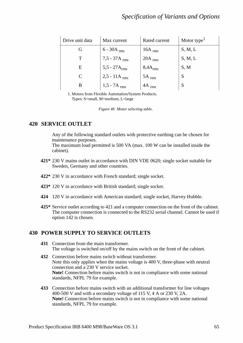
Specification of Variants and Options
Figure 46 Motor selecting table.
420 SERVICE OUTLET
Any of the following standard outlets with protective earthing can be chosen for maintenance purposes.The maximum load permitted is 500 VA (max. 100 W can be installed inside the cabinet).
421* 230 V mains outlet in accordance with DIN VDE 0620; single socket suitable for Sweden, Germany and other countries.
422* 230 V in accordance with French standard; single socket.
423* 120 V in accordance with British standard; single socket.
424 120 V in accordance with American standard; single socket, Harvey Hubble.
425* Service outlet according to 421 and a computer connection on the front of the cabinet. The computer connection is connected to the RS232 serial channel. Cannot be used if option 142 is chosen.
430 POWER SUPPLY TO SERVICE OUTLETS
431 Connection from the main transformer.The voltage is switched on/off by the mains switch on the front of the cabinet.
432 Connection before mains switch without transformer.Note this only applies when the mains voltage is 400 V, three-phase with neutralconnection and a 230 V service socket.Note! Connection before mains switch is not in compliance with some nationalstandards, NFPL 79 for example.
433 Connection before mains switch with an additional transformer for line voltages 400-500 V and with a secondary voltage of 115 V, 4 A or 230 V, 2A.Note! Connection before mains switch is not in compliance with some nationalstandards, NFPL 79 for example.
Drive unit data Max current Rated current Motor type1
1. Motors from Flexible Automation/System Products.Types: S=small, M=medium, L=large
G 6 - 30A rms 16A rms S, M, L
T 7,5 - 37A rms 20A rms S, M, L
E 5,5 - 27Arms 8,4Arms S, M
C 2,5 - 11A rms 5A rms S
B 1,5 - 7A rms 4A rms S
Product Specification IRB 6400 M98/BaseWare OS 3.1 65
Specification of Variants and Options
t back
439 Earth fault protection for service outlet.To increase personal safety, the service outlet can be supplied with an earth fault protection which trips at 30 mA earth current. The earth fault protection is placed next to the service outlet (see Figure 45). Voltage range: 110 - 240 V AC.
470 DISK DRIVE COOLING
The disk drive normally works well at temperatures up to 40oC (104oF). At higher temperatures a cooling device for the drive is necessary to ensure good functionality. The disk drive will not deteriorate at higher temperatures but there will be an increase in the number of reading/writing problems as the temperature increases.
471 No
472 Yes
620 KIT FOR LIMITING WORKING SPACE
To increase the safety of the robot, the working range of axes 1, 2 and 3 can be restricted by extra mechanical stops.
621 Axis 12 stops which allow the working range to be restricted in any increment of 20o.
622 Axis 2 6 stops which allow the working range to be restricted in increments of 20o. Each stop decreases the motion by 20°. This means that the motion can be decreased by 6 x 20° from the maximum axis motion.
623 Axis 36 stops which allow the working range to be restricted in increments of 20o. Each stop decreases the motion by 20°. This means that the motion can be decreased by 6 x 20° from the maximum axis motion.
624 Axis 1, 2 and 3Kit including option 621, 622 and 623.
630 TEACH PENDANT LIGHTINGThe teach pendant is, as standard, equipped with a sharp and clear display withoulighting. Back lighting is available as an option.
632 Without back lighting
631 With back lighting
66 Product Specification IRB 6400 M98/BaseWare OS 3.1
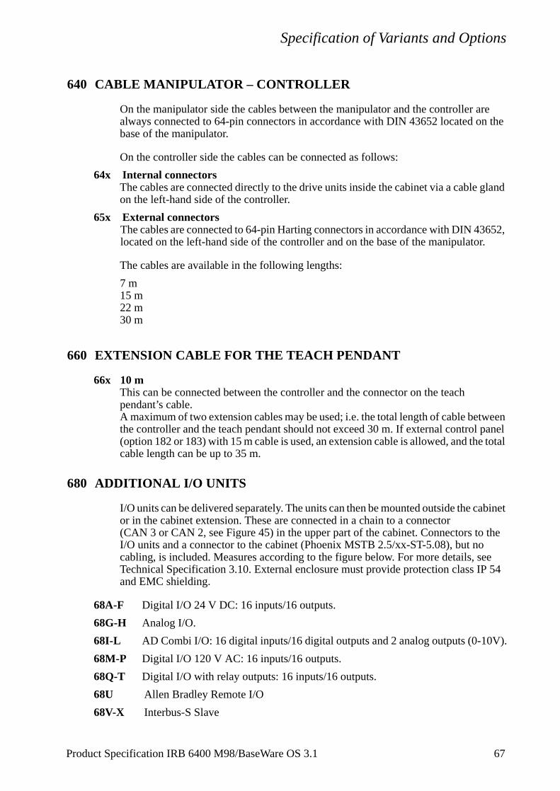
Specification of Variants and Options
ween panel total
abinet
the ee
V).
640 CABLE MANIPULATOR – CONTROLLER
On the manipulator side the cables between the manipulator and the controller are always connected to 64-pin connectors in accordance with DIN 43652 located on the base of the manipulator.
On the controller side the cables can be connected as follows:
64x Internal connectorsThe cables are connected directly to the drive units inside the cabinet via a cable gland on the left-hand side of the controller.
65x External connectorsThe cables are connected to 64-pin Harting connectors in accordance with DIN 43652, located on the left-hand side of the controller and on the base of the manipulator.
The cables are available in the following lengths:
7 m15 m22 m30 m
660 EXTENSION CABLE FOR THE TEACH PENDANT
66x 10 mThis can be connected between the controller and the connector on the teach pendant’s cable.A maximum of two extension cables may be used; i.e. the total length of cable betthe controller and the teach pendant should not exceed 30 m. If external control (option 182 or 183) with 15 m cable is used, an extension cable is allowed, and thecable length can be up to 35 m.
680 ADDITIONAL I/O UNITS
I/O units can be delivered separately. The units can then be mounted outside the cor in the cabinet extension. These are connected in a chain to a connector (CAN 3 or CAN 2, see Figure 45) in the upper part of the cabinet. Connectors toI/O units and a connector to the cabinet (Phoenix MSTB 2.5/xx-ST-5.08), but nocabling, is included. Measures according to the figure below. For more details, sTechnical Specification 3.10. External enclosure must provide protection class IP 54 and EMC shielding.
68A-F Digital I/O 24 V DC: 16 inputs/16 outputs.
68G-H Analog I/O.
68I-L AD Combi I/O: 16 digital inputs/16 digital outputs and 2 analog outputs (0-10
68M-P Digital I/O 120 V AC: 16 inputs/16 outputs.
68Q-T Digital I/O with relay outputs: 16 inputs/16 outputs.
68U Allen Bradley Remote I/O
68V-X Interbus-S Slave
Product Specification IRB 6400 M98/BaseWare OS 3.1 67
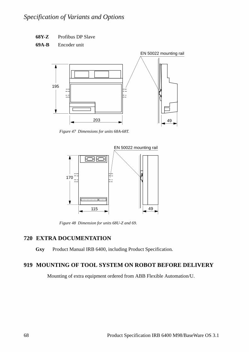
Specification of Variants and Options
68Y-Z Profibus DP Slave
69A-B Encoder unit
Figure 47 Dimensions for units 68A-68T.
Figure 48 Dimension for units 68U-Z and 69.
720 EXTRA DOCUMENTATION
Gxy Product Manual IRB 6400, including Product Specification.
919 MOUNTING OF TOOL SYSTEM ON ROBOT BEFORE DELIVERY
Mounting of extra equipment ordered from ABB Flexible Automation/U.
195
203 49
EN 50022 mounting rail
49115
170
EN 50022 mounting rail
68 Product Specification IRB 6400 M98/BaseWare OS 3.1
Accessories
5 Accessories
There is a range of tools and equipment available, specially designed for the robot.
Software options for robot and PC
For more information, see Product Specification RobotWare.
Robot Peripherals
- Track Motion
- Tool System
- Motor Units
- Spot welding system for transformer gun
Product Specification IRB 6400 M98/BaseWare OS 3.1 69

Accessories
70 Product Specification IRB 6400 M98/BaseWare OS 3.1

Product Specification RobotWare
CONTENTSPage
1 Introduction ..................................................................................................................... 3
2 BaseWare OS ................................................................................................................... 5
2.1 The Rapid Language and Environment .................................................................. 5
2.2 Exception handling ................................................................................................. 6
2.3 Motion Control ....................................................................................................... 7
2.4 Safety ...................................................................................................................... 9
2.5 I/O System .............................................................................................................. 10
3 BaseWare Options ........................................................................................................... 11
3.1 Advanced Functions 3.1 ......................................................................................... 11
3.2 Advanced Motion 3.1 ............................................................................................. 16
3.3 Multitasking 3.1...................................................................................................... 19
3.4 FactoryWare Interface 3.1 ...................................................................................... 20
3.5 RAP Communication 3.1........................................................................................ 22
3.6 Ethernet Services 3.1 .............................................................................................. 23
3.7 Load Identification and Collision Detection 3.1 (LidCode)................................... 24
3.8 ScreenViewer 3.1.................................................................................................... 25
3.9 Conveyor Tracking 3.1 ........................................................................................... 27
3.10 I/O Plus 3.1 ........................................................................................................... 28
4 ProcessWare..................................................................................................................... 29
4.1 ArcWare 3.1............................................................................................................ 29
4.2 ArcWare Plus 3.1 ................................................................................................... 32
4.3 SpotWare 3.1.......................................................................................................... 33
4.4 SpotWare Plus 3.1................................................................................................... 37
4.5 GlueWare 3.1 ......................................................................................................... 38
4.6 PaintWare 3.1.......................................................................................................... 40
4.7 PalletWare............................................................................................................... 42
5 Memory and Documentation ......................................................................................... 45
5.1 Available memory................................................................................................... 45
5.2 Teach Pendant Language ........................................................................................ 46
5.3 Robot Documentation............................................................................................. 46
6 DeskWare ......................................................................................................................... 47
6.1 DeskWare Office 3.0 .............................................................................................. 47
6.2 Programming Station 3.0........................................................................................ 50
6.3 Training Center 3.0 ................................................................................................. 56
6.4 Library 3.0 .............................................................................................................. 58
6.5 Robot Lab 3.0 ......................................................................................................... 60
Product Specification RobotWare for BaseWare OS 3.1 1
Product Specification RobotWare
7 FactoryWare .................................................................................................................... 63
7.1 RobComm 3.0 ........................................................................................................ 63
7.2 RobView 3.1 ........................................................................................................... 67
7.3 DDE Server 2.3 ...................................................................................................... 74
7.4 ScreenMaker 3.0..................................................................................................... 78
8 Index................................................................................................................................. 79
2 Product Specification RobotWare for BaseWare OS 3.1
Introduction
1 Introduction
RobotWare is a family of software products from ABB Flexible Automation designed to make you more productive and lower your cost of owning and operating a robot.
ABB Flexible Automation has invested many man-years into the development of these products and they represent knowledge and experience based on several thousand robot installations.
Within the RobotWare family there are five classes of products:
BaseWare OS - This is the operating system of the robot and constitutes the kernel of the RobotWare family. BaseWare OS provides all the necessary features for fundamental robot programming and operation. It is an inherent part of the robot but can be provided separately for upgrading purposes.
BaseWare Options - These products are options that run on top of BaseWare OS of the robot. They represent functionality for robot users that need additional functionality, for example run multitasking, transfer information from file to robot, communicate with a PC, perform advanced motion tasks etc.
ProcessWare - ProcessWare products are designed for specific process applications like welding, gluing and painting. They are primarily designed to improve the process result and to simplify installation and programming of applications. These products also run on top of BaseWare OS.
DeskWare - This is a set of Windows-based PC products for a wide range of uses like: creating robot programs, training people on how to use robots, keeping track of robot programs and on-line documentation. The purpose is to lower the indirect cost of owning a robot.
FactoryWare - By combining the power of PCs with robots, the possibilities are almost unlimited. The FactoryWare products are intended to be used in PCs connected to robots, on the factory floor or in the office. These tools can be typically used for such things as programmable operator interfaces, work monitoring or cell supervision.
Product Specification RobotWare for BaseWare OS 3.1 3

Introduction
4 Product Specification RobotWare for BaseWare OS 3.1
Rapid Language and Environment
Product Specification RobotWare for BaseWare OS 3.1 5
2 BaseWare OS
Only a very superficial overview of BaseWare OS is given here. For details, see references in Robot Documentation.
The properties of BaseWare OS can be split up in five main areas: The Rapid Language and Environment; Exception handling; Motion Control; Safety; the I/O System.
2.1 The Rapid Language and Environment
The Rapid language is a well balanced combination of simplicity, flexibility and powerfulness. It contains the following concepts:
- Hierarchical and modular program structure to support structured programming and reuse.
- Routines can be Functions or Procedures.
- Local or global data and routines.
- Data typing, including structured and array data types.
- User defined names (shop floor language) on variables, routines and I/O.
- Extensive program flow control.
- Arithmetic and logical expressions.
- Interrupt handling.
- Error handling (for exception handling in general, see Exception handling).
- User defined instructions (appear as an inherent part of the system).
- Backward handler (user definition of how a procedure should behave when stepping backwards).
- Many powerful built-in functions, e.g mathematics and robot specific.
- Unlimited language (no max. number of variables etc., only memory limited).
- Windows based man machine interface with built-in Rapid support (e.g. user defined pick lists).
Exception handling
6 Product Specification RobotWare for BaseWare OS 3.1
2.2 Exception handling
Many advanced features are available to make fast error recovery possible. Characteristic is that the error recovery features are easy to adapt to a specific installation in order to minimise down time. Examples:
- Error Handlers (automatic recovery often possible without stopping produc-tion).
- Restart on Path.
- Power failure restart.
- Service routines.
- Error messages: plain text with remedy suggestions, user defined messages.
- Diagnostic tests.
- Event logging.
Motion Control
two
n and is not ad
axes.
y big ig, tion.
2.3 Motion Control
TrueMoveTM
Very accurate path and speed, based on advanced dynamic modelling. Speed independent path. Flexible and intuitive way to specify corner zones (e.g. possibility to have separate zone sizes for Tool Centre Point (TCP) path and for tool reorientation).
QuickMoveTM
By use of the dynamic model, the robot always and automatically optimises its performance for the shortest possible cycle time. No need for manual tuning! This is achieved without compromising the path accuracy.
Coordinate Systems
A very powerful concept of multiple coordinate systems that facilitates jogging, program adjustment, copying between robots, off-line programming, sensor based applications, external axes co-ordination etc. Full support for TCP attached to the robot or fixed in the cell (“Stationary TCP”). Note that also joint coordinate movements(MoveJ) are recalculated when a coordinate system is adjusted.
Singularity handling
The robot can pass through singular points in a controlled way, i.e. points whereaxes coincide.
Motion Supervision
The behaviour of the motion system is continuously monitored as regards positiospeed level to detect abnormal conditions and quickly stop the robot if something OK. A further monitoring function, Collision Detection, is optional (see option “LoIdentification and Collision Detection”).
External axes
Very flexible possibilities to configure external axes. Includes for instance high performance coordination with robot movement and shared drive unit for several
Big Inertia
One side effect of the dynamic model concept is that the system can handle verload inertias by automatically adapting the performance to a suitable level. For bflexible objects it is possible to optimise the servo tuning to minimise load oscilla
Product Specification RobotWare for BaseWare OS 3.1 7

Motion Control
Soft Servo
Any axis (also external) can be switched to soft servo mode, which means that it will adopt a spring-like behaviour.
8 Product Specification RobotWare for BaseWare OS 3.1
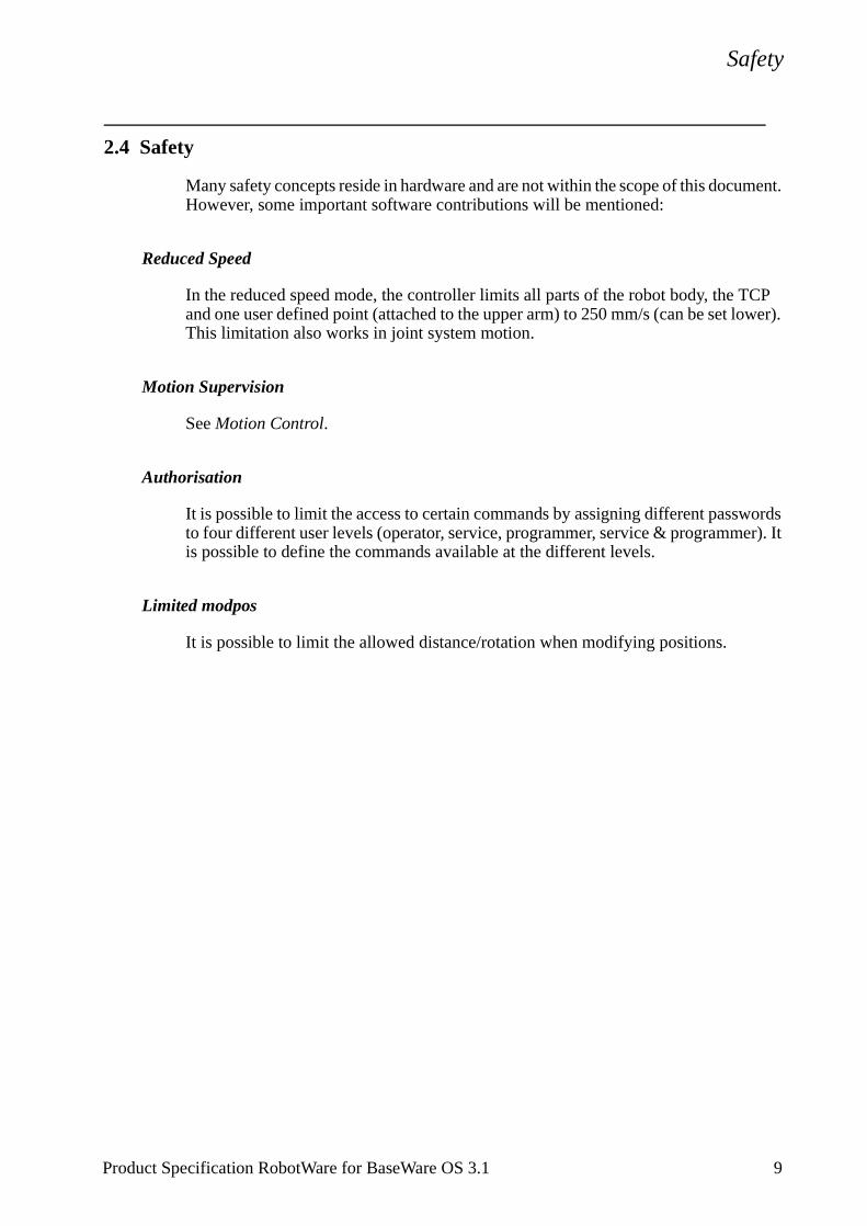
Safety
Product Specification RobotWare for BaseWare OS 3.1 9
2.4 Safety
Many safety concepts reside in hardware and are not within the scope of this document. However, some important software contributions will be mentioned:
Reduced Speed
In the reduced speed mode, the controller limits all parts of the robot body, the TCP and one user defined point (attached to the upper arm) to 250 mm/s (can be set lower). This limitation also works in joint system motion.
Motion Supervision
See Motion Control.
Authorisation
It is possible to limit the access to certain commands by assigning different passwords to four different user levels (operator, service, programmer, service & programmer). It is possible to define the commands available at the different levels.
Limited modpos
It is possible to limit the allowed distance/rotation when modifying positions.

I/O System
10 Product Specification RobotWare for BaseWare OS 3.1
2.5 I/O System
Elementary I/O
Robust and fast distributed system built on CAN/DeviceNet with the following features:
- Named signals and actions with mapping to physical signal (“gripper close” instead of “set output 1”).
- Flexible cross connections.
- Up to 512 signals available (one signal = single DI or DO, group of DI or DO, AI or AO).
- Grouping of signals to form integer values.
- Sophisticated error handling.
- Selectable “trust level” (i.e. what action to take when a unit is “lost”).
- Program controlled enabling/disabling of I/O units.
- Scaling of analog signals.
- Filtering.
- Polarity definition.
- Pulsing.
- TCP-proportional analog signal.
- Programmable delays.
- Simulated I/O (for forming cross connections or logical conditions without need the for physical hardware).
- Accurate coordination with motion.
Serial I/O
XON/XOFF or SLIP.
Memory I/O
RAM disk and floppy disk.
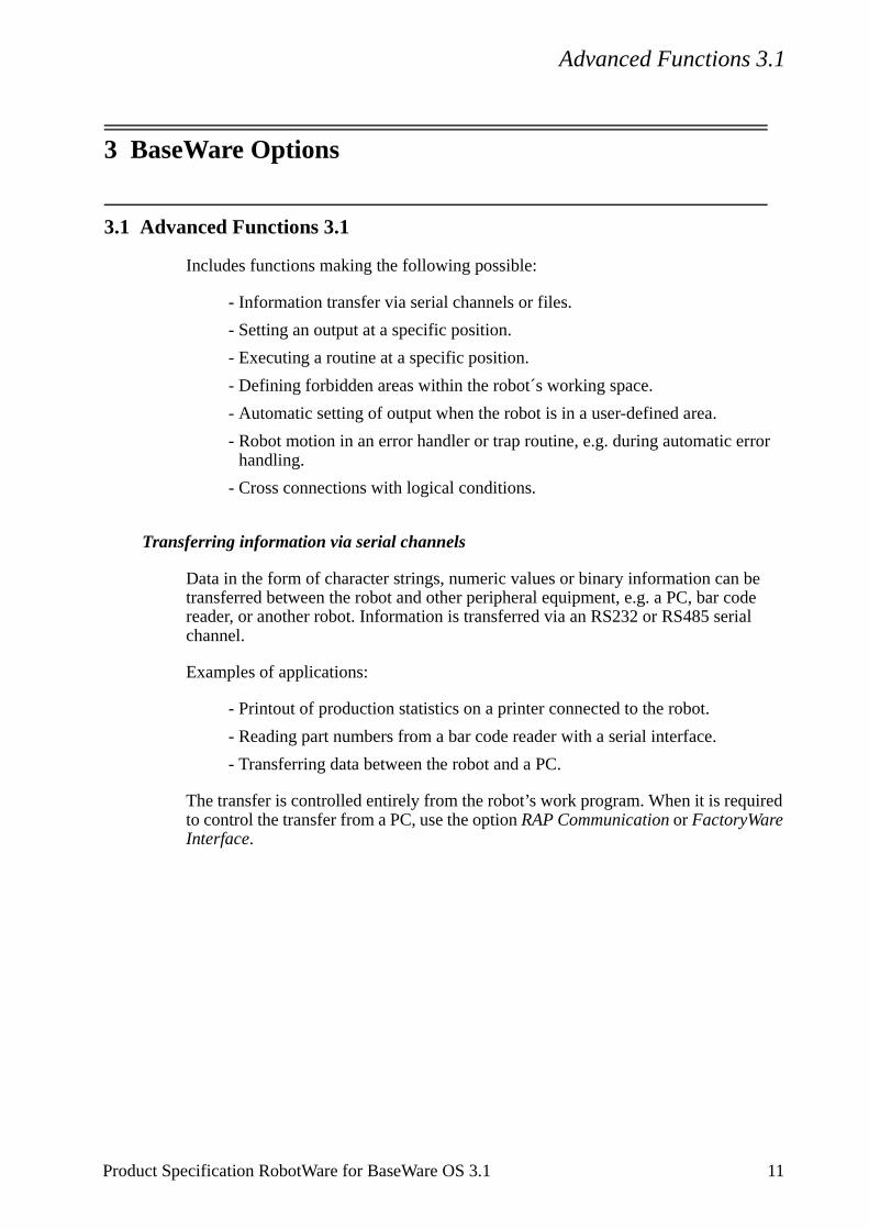
Advanced Functions 3.1
or
e de l
ired
3 BaseWare Options
3.1 Advanced Functions 3.1
Includes functions making the following possible:
- Information transfer via serial channels or files.
- Setting an output at a specific position.
- Executing a routine at a specific position.
- Defining forbidden areas within the robot´s working space.
- Automatic setting of output when the robot is in a user-defined area.
- Robot motion in an error handler or trap routine, e.g. during automatic errhandling.
- Cross connections with logical conditions.
Transferring information via serial channels
Data in the form of character strings, numeric values or binary information can btransferred between the robot and other peripheral equipment, e.g. a PC, bar coreader, or another robot. Information is transferred via an RS232 or RS485 seriachannel.
Examples of applications:
- Printout of production statistics on a printer connected to the robot.
- Reading part numbers from a bar code reader with a serial interface.
- Transferring data between the robot and a PC.
The transfer is controlled entirely from the robot’s work program. When it is requto control the transfer from a PC, use the option RAP Communication or FactoryWare Interface.
Product Specification RobotWare for BaseWare OS 3.1 11
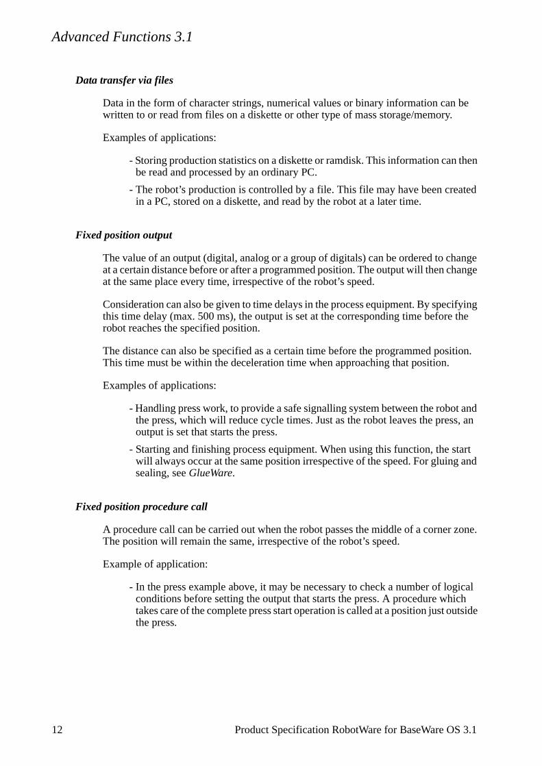
Advanced Functions 3.1
ted
ange ange
ifying the
ition.
t and s, an
tart and
zone.
gical ich utside
Data transfer via files
Data in the form of character strings, numerical values or binary information can be written to or read from files on a diskette or other type of mass storage/memory.
Examples of applications:
- Storing production statistics on a diskette or ramdisk. This information can then be read and processed by an ordinary PC.
- The robot’s production is controlled by a file. This file may have been creain a PC, stored on a diskette, and read by the robot at a later time.
Fixed position output
The value of an output (digital, analog or a group of digitals) can be ordered to chat a certain distance before or after a programmed position. The output will then chat the same place every time, irrespective of the robot’s speed.
Consideration can also be given to time delays in the process equipment. By specthis time delay (max. 500 ms), the output is set at the corresponding time beforerobot reaches the specified position.
The distance can also be specified as a certain time before the programmed posThis time must be within the deceleration time when approaching that position.
Examples of applications:
- Handling press work, to provide a safe signalling system between the robothe press, which will reduce cycle times. Just as the robot leaves the presoutput is set that starts the press.
- Starting and finishing process equipment. When using this function, the swill always occur at the same position irrespective of the speed. For gluingsealing, see GlueWare.
Fixed position procedure call
A procedure call can be carried out when the robot passes the middle of a cornerThe position will remain the same, irrespective of the robot’s speed.
Example of application:
- In the press example above, it may be necessary to check a number of loconditions before setting the output that starts the press. A procedure whtakes care of the complete press start operation is called at a position just othe press.
12 Product Specification RobotWare for BaseWare OS 3.1
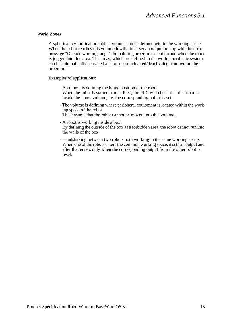
Advanced Functions 3.1
robot stem, e
ork-
into
e.t and
is
World Zones
A spherical, cylindrical or cubical volume can be defined within the working space. When the robot reaches this volume it will either set an output or stop with the error message “Outside working range”, both during program execution and when the is jogged into this area. The areas, which are defined in the world coordinate sycan be automatically activated at start-up or activated/deactivated from within thprogram.
Examples of applications:
- A volume is defining the home position of the robot.When the robot is started from a PLC, the PLC will check that the robot isinside the home volume, i.e. the corresponding output is set.
- The volume is defining where peripheral equipment is located within the wing space of the robot.This ensures that the robot cannot be moved into this volume.
- A robot is working inside a box.By defining the outside of the box as a forbidden area, the robot cannot runthe walls of the box.
- Handshaking between two robots both working in the same working spacWhen one of the robots enters the common working space, it sets an outpuafter that enters only when the corresponding output from the other robotreset.
Product Specification RobotWare for BaseWare OS 3.1 13

Advanced Functions 3.1
ng ing be ault
go to
’s can
gh.
5=1
Movements in interrupt routines and error handlers
This function makes it possible to temporarily interrupt a movement which is in progress and then start a new movement which is independent of the first one. The robot stores information about the original movement path which allows it to be resumed later.
Examples of applications:
- Cleaning the welding gun when a welding fault occurs. When a welding fault occurs, there is normally a jump to the program’s error handler. The weldimovement in progress can be stored and the robot is ordered to the cleanposition so that the nozzle can be cleaned. The welding process can thenrestarted, with the correct parameters, at the position where the welding foccurred. This is all automatic, without any need to call the operator. (Thisrequires options ArcWare or ArcWare Plus.)
- Via an input, the robot can be ordered to interrupt program execution and a service position, for example. When program execution is later restarted(manually or automatically) the robot resumes the interrupted movement.
Cross-connections with logical conditions
Logical conditions for digital input and output signals can be defined in the robotsystem parameters using AND, OR and NOT. Functionality similar to that of a PLCbe obtained in this way.
Example:
- Output 1 = Input 2 AND Output 5.
- Input 3 = Output 7 OR NOT Output 8.
Examples of applications:
- Program execution to be interrupted when both inputs 3 and 4 become hi
- A register is to be incremented when input 5 is set, but only when output and input 3=0.
14 Product Specification RobotWare for BaseWare OS 3.1
Advanced Functions 3.1
RAPID instructions and functions included in this option
Open Opens a file or serial channelClose Closes a file or serial channel Write Writes to a character-based file or serial channelWriteBin Writes to a binary file or serial channelWriteStrBin Writes a string to a binary serial channelReadNum Reads a number from a file or serial channelReadStr Reads a string from a file or serial channelReadBin Reads from a binary file or serial channelRewind Rewind file positionWZBoxDef Define a box shaped world zoneWZCylDef Define a cylinder shaped world zoneWZLimSup Activate world zone limit supervisionWZSphDef Define a sphere shaped world zoneWZDOSet Activate world zone to set digital outputWZDisable Deactivate world zone supervisionWZEnable Activate world zone supervisionWZFree Erase world zone supervisionStorePath Stores the path when an interrupt or error occursRestoPath Restores the path after an interrupt/errorTriggC Position fix output/interrupt during circular movementTriggL Position fix output/interrupt during linear movement TriggJ Position fix output/interrupt during joint movementTriggIO Definition of trigger conditions for one outputTriggEquip Definition of trigger conditions for process equipment with
time delayTriggInt Definition of trigger conditions for an interruptMoveCSync Position fix procedure call during circular movementMoveLSync Position fix procedure call during linear movementMoveJSync Position fix procedure call during join movement
Product Specification RobotWare for BaseWare OS 3.1 15
Advanced Motion 3.1
ecial n
3.2 Advanced Motion 3.1
Contains functions that offer the following possibilities:
- Resetting the work area for an axis.
- Independent movements.
- Contour tracking.
- Coordinated motion with external manipulators.
Resetting the work area for an axis
The current position of a rotating axis can be adjusted a number of complete turns without having to make any movements.
Examples of applications:
- When polishing, a large work area is sometimes needed on the robot axis 4 or axis 6 in order to be able to carry out final polishing without stopping. Assume that the axis has rotated 3 turns, for example. It can now be reset using this func-tion, without having to physically rotate it back again. Obviously this will reduce cycle times.
- When arc welding, the work object is often fitted to a rotating external axis. If this axis is rotated more than one turn during welding, the cycle time can be reduced because it is not necessary to rotate the axis back between welding cycles.
Coordinated motion with multi-axis manipulators
Coordinated motion with multi-axis manipulators or robot carriers (gantries) requires the Advanced Motion option. Note that simultaneous coordination with several single axis manipulators, e.g. track motion and workpiece manipulator, does not require Advanced Motion.
Note! There is a built-in general method for defining the geometry for a manipulator comprising two rotating axes (see User’s Guide, Calibration). For other types of manipulators/robot carriers, comprising up to six linear and/or rotating axes, a spconfiguration file is needed. Please contact your nearest ABB Flexible AutomatioCentre.
16 Product Specification RobotWare for BaseWare OS 3.1
Advanced Motion 3.1
ces
con-the is in
s, a d.
ires
that e
ying
Contour tracking
Path corrections can be made in the path coordinate system. These corrections will take effect immediately, also during movement between two positions. The path corrections must be entered from within the program. An interrupt or multitasking is therefore required to activate the correction during motion.
Example of application:
- A sensor is used to define the robot input for path correction during motion. The input can be defined via an analog input, a serial channel or similar. Multitask-ing or interrupts are used to read this information at specific intervals. Based on the input value, the path can then be adjusted.
Independent movements
A linear or rotating axis can be run independently of the other axes in the robot system. The independent movement can be programmed as an absolute or relative position. A continuous movement with a specific speed can also be programmed.
Examples of applications:
- A robot is working with two different stations (external axes). First, a work object located at station 1 is welded. When this operation is completed, station 1 is moved to a position where it is easy to change the work object and at the same time the robot welds the work object at station 2. Station 1 is moved inde-pendently of the robot’s movement, which simplifies programming and reduthe cycle time.
- The work object is located on an external axis that rotates continuously at astant speed. In the mean time, the robot sprays plasma, for example, on work object. When this is finished the work area is reset for the external axorder to shorten the cycle time.
Friction Compensation
During low speed (10-100 mm/s) cutting of fine profiles, in particular small circlefriction effect, typically in the form of approximately 0.5 mm “bumps”, can be noteAdvanced Motion offers a possibility of compensating for these frictional effects.Typically a 0.5 mm “bump” can be reduced to about 0.1 mm. This, however, requcareful tuning of the friction level (see User’s Guide for tuning procedure). Note even with careful tuning, there is no guarantee that “perfect” paths can always bgenerated.
For the IRB 6400 family of robots, no significant effects can be expected by applFriction Compensation.
Product Specification RobotWare for BaseWare OS 3.1 17
Advanced Motion 3.1
ee
ls.
ns
e
he
External Drive System
With Advanced Motion, the possibility to connect off-the-shelf standard drive systems for controlling external axes is available. This can be of interest, for example, when the power of the available S4C drives does not match the requirements.
There are two alternatives:
- The Atlas Copco Controls´ stand alone servo amplifier DMC.
- The Atlas Copco Controls´ FBU (Field Bus Unit) that can handle up to threxternal drive units per FBU unit. These can be connected to analog outputs (+/- 10 V) or a field bus.The drive board can thus be of virtually any make and type.
For further information about DMC and FBU, please contact Atlas Copco Contro
NOTE! The DMC/FBU must be equipped with Atlas Copco Controls option C.
RAPID instructions and functions included in this option
IndReset Resetting the work area for an axis IndAMove Running an axis independently to an absolute positionIndDMove Running an axis independently for a specified distanceIndRMove Running an axis independently to a position within one
revolution, without taking into consideration the number of turthe axis had rotated earlier
IndCMove Running an axis continuously in independent modeIndInpos Checking whether or not an independent axis has reached th
programmed positionIndSpeed Checking whether or not an independent axis has reached t
programmed speedCorrCon Activating path correctionCorrWrite Changing path correctionCorrRead Read current path correctionCorrDiscon Deactivating path correctionCorrClear Removes all correction generators
18 Product Specification RobotWare for BaseWare OS 3.1
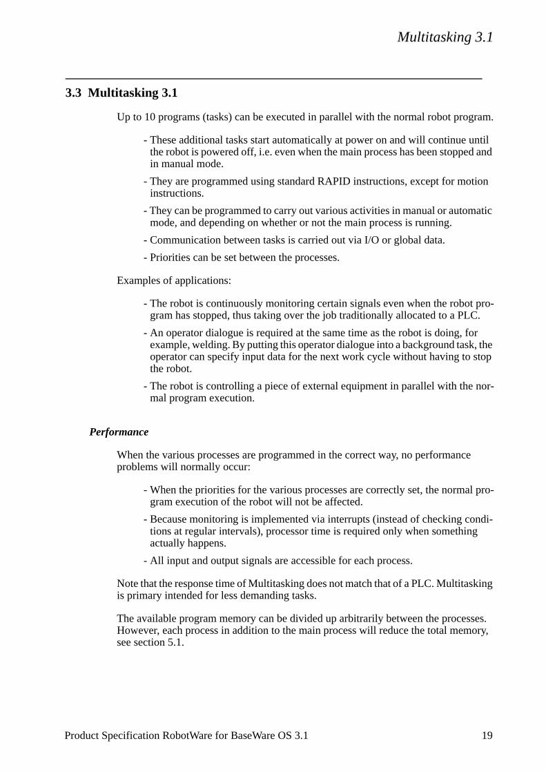
Multitasking 3.1
Product Specification RobotWare for BaseWare OS 3.1 19
3.3 Multitasking 3.1
Up to 10 programs (tasks) can be executed in parallel with the normal robot program.
- These additional tasks start automatically at power on and will continue until the robot is powered off, i.e. even when the main process has been stopped and in manual mode.
- They are programmed using standard RAPID instructions, except for motion instructions.
- They can be programmed to carry out various activities in manual or automatic mode, and depending on whether or not the main process is running.
- Communication between tasks is carried out via I/O or global data.
- Priorities can be set between the processes.
Examples of applications:
- The robot is continuously monitoring certain signals even when the robot pro-gram has stopped, thus taking over the job traditionally allocated to a PLC.
- An operator dialogue is required at the same time as the robot is doing, for example, welding. By putting this operator dialogue into a background task, the operator can specify input data for the next work cycle without having to stop the robot.
- The robot is controlling a piece of external equipment in parallel with the nor-mal program execution.
Performance
When the various processes are programmed in the correct way, no performance problems will normally occur:
- When the priorities for the various processes are correctly set, the normal pro-gram execution of the robot will not be affected.
- Because monitoring is implemented via interrupts (instead of checking condi-tions at regular intervals), processor time is required only when something actually happens.
- All input and output signals are accessible for each process.
Note that the response time of Multitasking does not match that of a PLC. Multitasking is primary intended for less demanding tasks.
The available program memory can be divided up arbitrarily between the processes. However, each process in addition to the main process will reduce the total memory, see section 5.1.
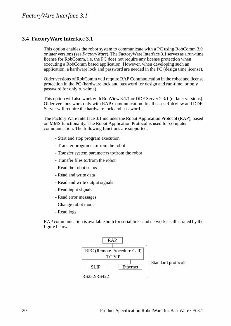
FactoryWare Interface 3.1
3.4 FactoryWare Interface 3.1
This option enables the robot system to communicate with a PC using RobComm 3.0 or later versions (see FactoryWare). The FactoryWare Interface 3.1 serves as a run-time license for RobComm, i.e. the PC does not require any license protection when executing a RobComm based application. However, when developing such an application, a hardware lock and password are needed in the PC (design time license).
Older versions of RobComm will require RAP Communication in the robot and license protection in the PC (hardware lock and password for design and run-time, or only password for only run-time).
This option will also work with RobView 3.1/1 or DDE Server 2.3/1 (or later versions). Older versions work only with RAP Communication. In all cases RobView and DDE Server will require the hardware lock and password.
The Factory Ware Interface 3.1 includes the Robot Application Protocol (RAP), based on MMS functionality. The Robot Application Protocol is used for computer communication. The following functions are supported:
- Start and stop program execution
- Transfer programs to/from the robot
- Transfer system parameters to/from the robot
- Transfer files to/from the robot
- Read the robot status
- Read and write data
- Read and write output signals
- Read input signals
- Read error messages
- Change robot mode
- Read logs
RAP communication is available both for serial links and network, as illustrated by the figure below.
RAP
RPC (Remote Procedure Call)TCP/IP
SLIP
RS232/RS422
Standard protocolsEthernet
20 Product Specification RobotWare for BaseWare OS 3.1
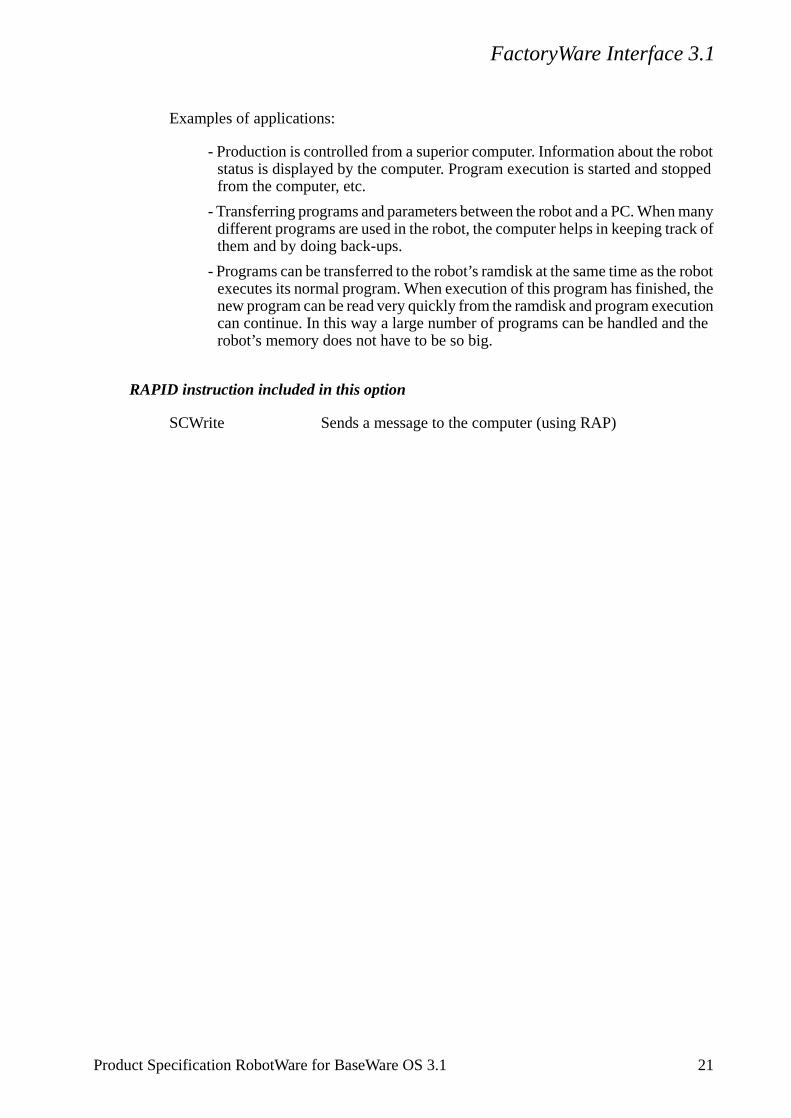
FactoryWare Interface 3.1
robot , the
ution the
Examples of applications:
- Production is controlled from a superior computer. Information about the robot status is displayed by the computer. Program execution is started and stopped from the computer, etc.
- Transferring programs and parameters between the robot and a PC. When many different programs are used in the robot, the computer helps in keeping track of them and by doing back-ups.
- Programs can be transferred to the robot’s ramdisk at the same time as theexecutes its normal program. When execution of this program has finishednew program can be read very quickly from the ramdisk and program execcan continue. In this way a large number of programs can be handled androbot’s memory does not have to be so big.
RAPID instruction included in this option
SCWrite Sends a message to the computer (using RAP)
Product Specification RobotWare for BaseWare OS 3.1 21
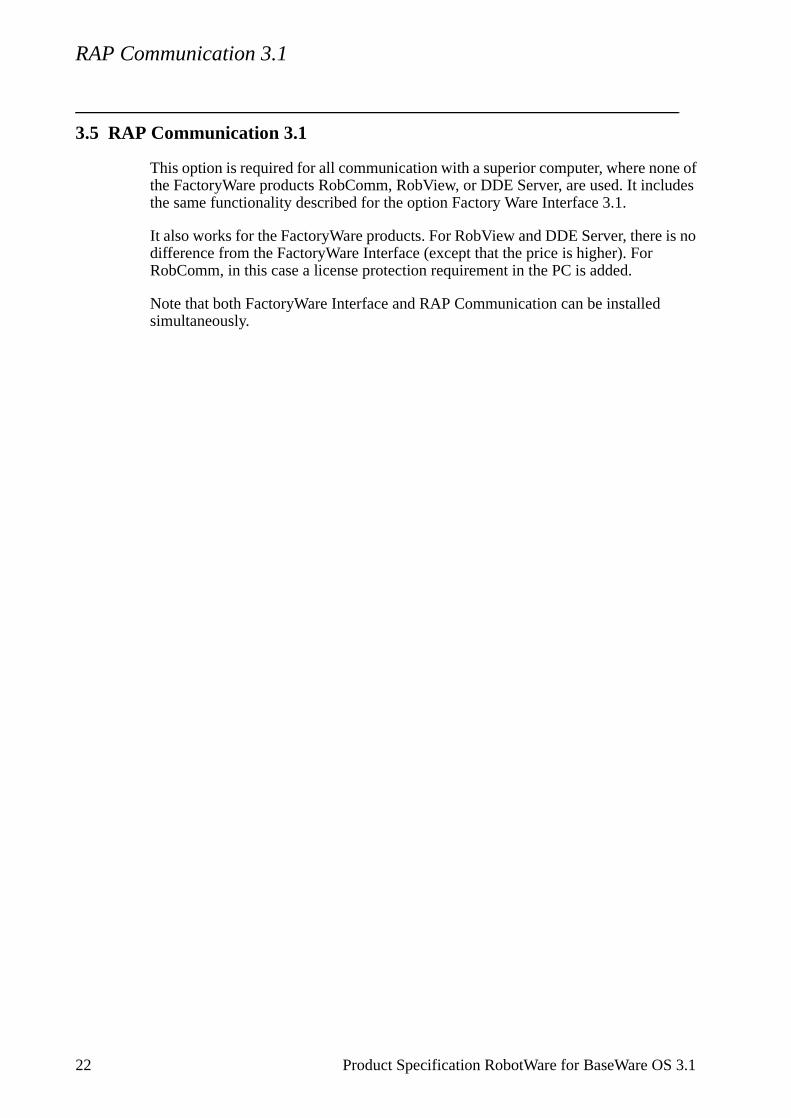
RAP Communication 3.1
22 Product Specification RobotWare for BaseWare OS 3.1
3.5 RAP Communication 3.1
This option is required for all communication with a superior computer, where none of the FactoryWare products RobComm, RobView, or DDE Server, are used. It includes the same functionality described for the option Factory Ware Interface 3.1.
It also works for the FactoryWare products. For RobView and DDE Server, there is no difference from the FactoryWare Interface (except that the price is higher). For RobComm, in this case a license protection requirement in the PC is added.
Note that both FactoryWare Interface and RAP Communication can be installed simultaneously.
Ethernet Services 3.1
Product Specification RobotWare for BaseWare OS 3.1 23
3.6 Ethernet Services 3.1
Information in mass storage, e.g. the hard disk in a PC, can be read directly from the robot. The robot control program can also be booted via Ethernet instead of using diskettes. This requires Ethernet hardware in the robot.
Examples of applications:
- All programs for the robot are stored in the PC. When a new part is to be pro-duced, i.e. a new program is to be loaded, the program can be read directly from the hard disk of the PC. This is done by a manual command from the teach pen-dant or an instruction in the program. If the option RAP Communication or FactoryWare Interface is used, it can also be done by a command from the PC (without using the ramdisk as intermediate storage).
- Several robots are connected to a PC via Ethernet. The control program and the user programs for all the robots are stored on the PC. A software update or a program backup can easily be executed from the PC.
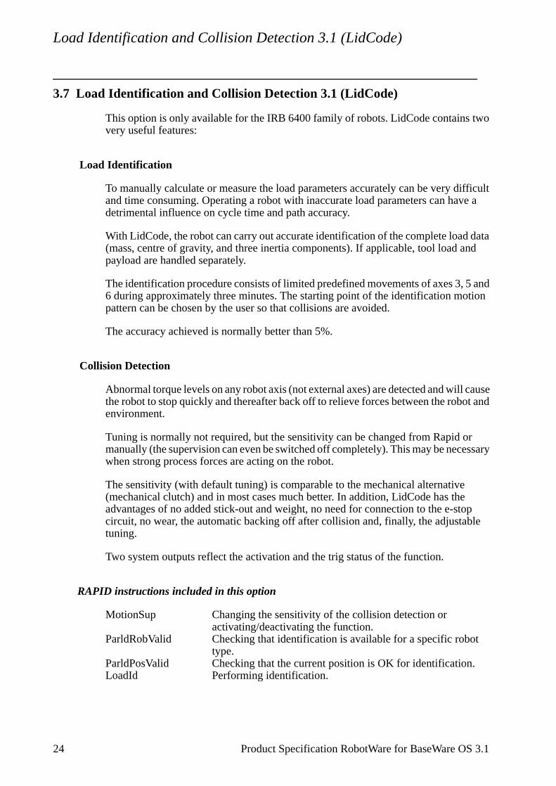
Load Identification and Collision Detection 3.1 (LidCode)
24 Product Specification RobotWare for BaseWare OS 3.1
3.7 Load Identification and Collision Detection 3.1 (LidCode)
This option is only available for the IRB 6400 family of robots. LidCode contains two very useful features:
Load Identification
To manually calculate or measure the load parameters accurately can be very difficult and time consuming. Operating a robot with inaccurate load parameters can have a detrimental influence on cycle time and path accuracy.
With LidCode, the robot can carry out accurate identification of the complete load data (mass, centre of gravity, and three inertia components). If applicable, tool load and payload are handled separately.
The identification procedure consists of limited predefined movements of axes 3, 5 and 6 during approximately three minutes. The starting point of the identification motion pattern can be chosen by the user so that collisions are avoided.
The accuracy achieved is normally better than 5%.
Collision Detection
Abnormal torque levels on any robot axis (not external axes) are detected and will cause the robot to stop quickly and thereafter back off to relieve forces between the robot and environment.
Tuning is normally not required, but the sensitivity can be changed from Rapid or manually (the supervision can even be switched off completely). This may be necessary when strong process forces are acting on the robot.
The sensitivity (with default tuning) is comparable to the mechanical alternative (mechanical clutch) and in most cases much better. In addition, LidCode has the advantages of no added stick-out and weight, no need for connection to the e-stop circuit, no wear, the automatic backing off after collision and, finally, the adjustable tuning.
Two system outputs reflect the activation and the trig status of the function.
RAPID instructions included in this option
MotionSup Changing the sensitivity of the collision detection or activating/deactivating the function.
ParldRobValid Checking that identification is available for a specific robot type.
ParldPosValid Checking that the current position is OK for identification.LoadId Performing identification.
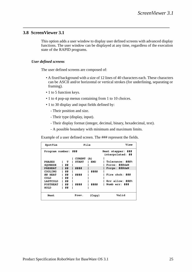
ScreenViewer 3.1
cters g or
3.8 ScreenViewer 3.1
This option adds a user window to display user defined screens with advanced display functions. The user window can be displayed at any time, regardless of the execution state of the RAPID programs.
User defined screens
The user defined screens are composed of:
• A fixed background with a size of 12 lines of 40 characters each. These characan be ASCII and/or horizontal or vertical strokes (for underlining, separatinframing).
• 1 to 5 function keys.
• 1 to 4 pop-up menus containing from 1 to 10 choices.
• 1 to 30 display and input fields defined by:
- Their position and size.
- Their type (display, input).
- Their display format (integer, decimal, binary, hexadecimal, text).
- A possible boundary with minimum and maximum limits.
Example of a user defined screen. The ### represent the fields.
| XT| ##| ##| ##| ##| ##| ##| ##| ##
Program number: ###
SpotTim File View
Next Prev. (Copy) Valid
PHASESSQUEEZEPREHEATCOOLING## HEATCOLDLASTCOLDPOSTHEATHOLD
Heat stepper: ###interpolated: ##
| START | | ####| | ####| | | ####|
| END| | | ####| | | | ####|
| Tolerance: ###%| Force: ###daN| Forge: ###daN| | Fire chck: ###| | Err allow: ###%| Numb err: ###
| CURENT (A) |
Product Specification RobotWare for BaseWare OS 3.1 25
ScreenViewer 3.1
Advanced Display functions
The user defined screens run independently of the RAPID programs.
Some events occur on a screen (new screen displayed, menu choice selected, function key pressed, field modified, ...). A list of user screen commands can be associated with any of these events, then when the event occurs, the command list will be executed.
A screen event can occur
- When a new screen is displayed (to initialize the screen contents).
- After a chosen interval (to refresh a screen).
- When a menu choice or a function key is selected (to execute a specific action, or change the screen).
- When a new value is entered in a field, or when a new field is selected (to exe-cute some specific action).
The commands that can be executed on screen events are
- Reading/writing RAPID or I/O data.
- Reading/writing fields contents.
- Arithmetical (+, -, /, *, div) or logical (AND, OR, NOT, XOR) operations on the data read.
- Comparing data read (=, <, >) and carrying out a command or not, depending on the comparison result.
- Displaying a different screen.
Capacities
The user screens can be grouped in a screen package file under a specific name. Up to 8 packages can be loaded at the same time.
A certain amount of memory (approx. 50 kbytes) is reserved for loading these screen packages.
- The screen package to be displayed is selected using the far right hand menu “View” (which shows a list of the screen packages installed).
26 Product Specification RobotWare for BaseWare OS 3.1
Conveyor Tracking 3.1
Product Specification RobotWare for BaseWare OS 3.1 27
3.9 Conveyor Tracking 3.1
Conveyor Tracking (also called Line Tracking) is the function whereby the robot follows a work object which is mounted on a moving conveyor. While tracking the conveyor, the programmed TCP speed relative to the work object will be maintained, even when the conveyor speed is changing slowly.
Note that hardware components for measuring the conveyor position are also necessary for this function. Please refer to the Product Specification for your robot.
Conveyor Tracking provides the following features:
- A conveyor can be defined as either linear or circular.
- It is possible to have two conveyors connected simultaneously and to switch between tracking the one or the other.
- Up to 254 objects can reside in an object queue which can be manipulated by RAPID instructions.
- It is possible to define a start window in which an object must be before track-ing can start.
- A maximum tracking distance may be specified.
- If the robot is mounted on a parallel track motion, then the system can be con-figured such that the track will follow the conveyor and maintain the relative position to the conveyor.
- Tracking of a conveyor can be activated “on the fly”, i.e. it is not necessary to stop in a fine point.
Performance
At 150 mm/s constant conveyor speed, the TCP will stay within +/-2 mm of the path as seen with no conveyor motion. When the robot is stationary relative to the conveyor, the TCP will remain within 0.7 mm of the intended position.
These values are valid as long as the robot is within its dynamic limits with the added conveyor motion and they require accurate conveyor calibration.
RAPID instructions included in this option
WaitWObj Connects to a work object in the start windowDropWObj Disconnects from the current object
I/O Plus 3.1
28 Product Specification RobotWare for BaseWare OS 3.1
3.10 I/O Plus 3.1
I/O Plus enables the S4C to use non-ABB I/O units. The following units are supported:
- Wago modules with DeviceNet fieldbus coupler, item 750-306 revision 3.
- Lutze IP67 module DIOPLEX-LS-DN 16E 744-215 revision 2 (16 digital input signals).
- Lutze IP67 module DIOPLEX-LS-DN 8E/8A 744-221 revision 1 (8 digital input signals and 8 digital output signals).
For more information on any of these untis, please contact the supplier.
The communication between these units and S4C has been verified (this does not, however, guarantee the internal functionality and quality of the units). Configuration data for the units is included.
In I/O Plus there is also support for a so-called “Welder”. This is a project specific spot welding timer, and is not intended for general use.
In addition to the above units, the I/O Plus option also opens up the possibility to use other digital I/O units that conform with the DeviceNet specification. ABB Robotics Products AB does not assume any responsibility for the functionality or quality of such units. The user must provide the appropriate configuration data.
ArcWare 3.1
4 ProcessWare
4.1 ArcWare 3.1
ArcWare comprises a large number of dedicated arc welding functions, which make the robot well suited for arc welding. It is a simple yet powerful program since both the positioning of the robot and the process control and monitoring are handled in one and the same instruction.
I/O signals, timing sequences and weld error actions can be easily configured to meet the requirements of a specific installation.
ArcWare functions
A few examples of some useful functions are given below.
Adaptation to different equipment
The robot can handle different types of weld controllers and other welding equipment. Normally communication with the welding controller uses parallel signals but a serial interface is also available.
Advanced process control
Voltage, wire feed rate, and other process data can be controlled individually for each weld or part of a weld. The process data can be changed at the start and finish of a welding process in such a way that the best process result is achieved.
Testing the program
When testing a program, welding, weaving or weld guiding can all be blocked. This provides a way of testing the robot program without having the welding equipment connected.
Automatic weld retry
A function that can be configured to order one or more automatic weld retries after a process fault.
Weaving
The robot can implement a number of different weaving patterns up to 10 Hz depending on robot type. These can be used to fill the weld properly and in the best possible way. Weaving movement can also be ordered at the start of the weld in order to facilitate the initial striking of the arc.
Product Specification RobotWare for BaseWare OS 3.1 29
ArcWare 3.1
Wire burnback and rollback
These are functions used to prevent the welding wire sticking to the work object.
Fine adjustment during program execution
The welding speed, wire feed rate, voltage and weaving can all be adjusted whilst welding is in progress. This makes trimming of the process much easier because the result can be seen immediately on the current weld. This can be done in both manual and automatic mode.
Weld Guiding
Weld guiding can be implemented using a number of different types of sensors. Please contact your nearest ABB Flexible Automation Centre for more information.
Interface signals
The following process signals are, if installed, handled automatically by ArcWare. The robot can also support dedicated signals for workpiece manipulators and sensors.
Digital outputs DescriptionPower on/off Turns weld on or offGas on/off Turns gas on or offWire feed on/off Turns wire feed on or offWire feed direction Feeds wire forward/backwardWeld error Weld errorError information Digital outputs for error identificationWeld program number Parallel port for selection of program number, or
3-bit pulse port for selection of program number, orSerial CAN/Devicenet communication
Digital inputs DescriptionArc OK Arc established; starts weld motion Voltage OK Weld voltage supervisionCurrent OK Weld current supervisionWater OK Water supply supervisionGas OK Gas supply supervisionWire feed OK Wire supply supervisionManual wire feed Manual command for wire feedWeld inhibit Blocks the welding processWeave inhibit Blocks the weaving processStop process Stops/inhibits execution of arc welding instructionsWirestick error Wirestick supervisionSupervision inhibit Program execution without supervisionTorch collision Torch collision supervision
Analog outputs DescriptionVoltage Weld voltageWire feed Velocity of wire feedCurrent Weld currentVoltage adjustment Voltage synergic line amplificationCurrent adjustment Current synergic line amplification
30 Product Specification RobotWare for BaseWare OS 3.1
ArcWare 3.1
Analog inputs (cont.) Description (cont.)
Voltage Weld voltage measurement for monitoring and supervision
Current Weld current measurement for monitoring and supervision
RAPID instructions included in this option
ArcL Arc welding with linear movementArcC Arc welding with circular movement
Product Specification RobotWare for BaseWare OS 3.1 31
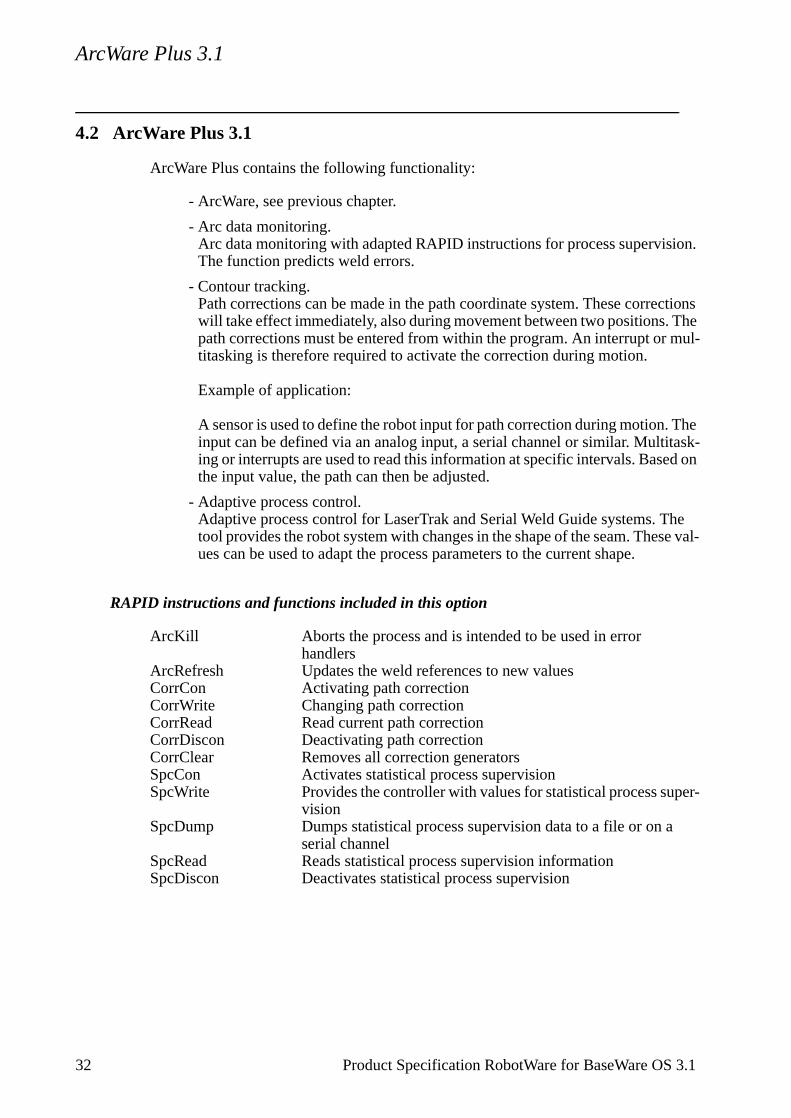
ArcWare Plus 3.1
32 Product Specification RobotWare for BaseWare OS 3.1
4.2 ArcWare Plus 3.1
ArcWare Plus contains the following functionality:
- ArcWare, see previous chapter.
- Arc data monitoring.Arc data monitoring with adapted RAPID instructions for process supervision. The function predicts weld errors.
- Contour tracking.Path corrections can be made in the path coordinate system. These corrections will take effect immediately, also during movement between two positions. The path corrections must be entered from within the program. An interrupt or mul-titasking is therefore required to activate the correction during motion.
Example of application:
A sensor is used to define the robot input for path correction during motion. The input can be defined via an analog input, a serial channel or similar. Multitask-ing or interrupts are used to read this information at specific intervals. Based on the input value, the path can then be adjusted.
- Adaptive process control.Adaptive process control for LaserTrak and Serial Weld Guide systems. The tool provides the robot system with changes in the shape of the seam. These val-ues can be used to adapt the process parameters to the current shape.
RAPID instructions and functions included in this option
ArcKill Aborts the process and is intended to be used in error handlers
ArcRefresh Updates the weld references to new valuesCorrCon Activating path correctionCorrWrite Changing path correctionCorrRead Read current path correctionCorrDiscon Deactivating path correctionCorrClear Removes all correction generatorsSpcCon Activates statistical process supervisionSpcWrite Provides the controller with values for statistical process super-
visionSpcDump Dumps statistical process supervision data to a file or on a
serial channelSpcRead Reads statistical process supervision informationSpcDiscon Deactivates statistical process supervision

SpotWare 3.1
ycle
meet
of
the es of
f the even
ed f the
se at
ot to start.
a user
4.3 SpotWare 3.1
SpotWare comprises a large number of dedicated spot welding functions which make the robot well suited for spot welding. It is a simple yet powerful program since both the positioning of the robot and the process control and monitoring are handled in one and the same instruction.
Cycle times can be shortened by means of closing the spot welding gun in advance, together with the fact that movement can commence immediately after a spot weld is completed. The robot’s self-optimising motion control, which results in fast acceleration and a quick approach to the spot weld, also contributes to making ctimes shorter.
I/O signals, timing sequences and weld error actions can be easily configured tothe requirements of a specific installation.
SpotWare functions
A few examples of some useful functions are given below.
Adaptation to different welding guns
Gun control (opening and closing) can be programmed freely to suit most types guns, irrespective of the signal interface.
Adaptation to different weld timers
The robot can handle different types of weld timers. Normally communication withweld timer uses parallel signals but a serial interface is also available for some typweld timers.
Continuous supervision of the welding equipment
If the option Multitasking is added, supervision can be implemented irrespective ospotweld instruction. For example, it is possible to monitor peripheral equipment when program execution has been stopped.
Closing the gun
It is possible to start closing the spot welding gun before reaching the programmpoint. By defining a time of closure, the gun can be closed correctly regardless ospeed of the robot. The cycle time is optimised when the gun is just about to clothe instant when the robot reaches the programmed point.
Constant squeeze time
Welding can be started directly as the gun closes, i.e. without waiting for the robreach its final position. This gives a constant time between gun closure and weld
Customised Move enable
The movement after a completed spot weld can be configured to start either on defined input signal or a delay time after weld ready.
Product Specification RobotWare for BaseWare OS 3.1 33
SpotWare 3.1
3
Immediate move after Move enable
The robot moves immediately when enable is given. This is achieved by preparing the next action while waiting for the current weld to be completed.
Gun control
The system supports double guns, small and large strokes and gun pressure control. Several guns can be controlled in the same program.
Testing the program
The program can be run one instruction at a time, both forwards and backwards. When it is run backwards, only motion instructions, together with an inverted gun movement, are executed. The program can also be test run without connecting a weld timer or spot welding gun. This makes the program easier to test.
Rewelds
A function that can be configured to order one or more automatic rewelds or, when the program is restarted after an error, a manual reweld.
Process error routines
In the event of a process error, installation-specific routines, such as go-to-service position, can be ordered manually. When the appropriate routine has been performed, the weld cycle continues from where it was interrupted.
Manual welding independent of positioning
A spot weld can be ordered manually at the current robot position. This is implemented in a similar way as for program execution, i.e. with gun control and process supervision. It is also possible to order a separate gun control with full supervision.
Interface signals
The following process signals are, if installed, handled automatically by SpotWare.
Digital outputs Descriptionstart 1 start signal to the weld timer (tip 1)start 2 start signal to the weld timer (tip 2)close tip 1 close gun (tip 1)close tip 2 close gun (tip 2)work select select work or retract stroke of the gunprogram parity weld program parity bitreset fault reset the weld timerprocess error operator request is set when an error occurscurrent enable weld inhibit to the weld timerp2 request set pressure 2p3 request set pressure 3p4 request set pressure 4weld power activate the weld power unit contactorwater start activate water cooling
4 Product Specification RobotWare for BaseWare OS 3.1
SpotWare 3.1
manual close gun close gun manuallymanual open gun open gun manuallymanual run process run a complete spot weldmanual skip process skip the ongoing actionmanual new data send data for the manual actionsprocess run process is executedinhibit move block spot welding movementweld error weld ready timeout
Digital output groups Descriptionprogram no. weld program numberinitiate used for several weld timers
Digital inputs Descriptionweld ready 1 weld, started with start 1, is finishedweld ready 2 weld, started with start 2, is finishedtip 1 open the gun (tip 1) is opentip 2 open the gun (tip 2) is opentip 1 retract the gun (tip 1) opened to retract stroketip 2 retract the gun (tip 2) opened to retract strokep1 OK pressure 1 is reachedp2 OK pressure 2 is reachedp3 OK pressure 3 is reachedp4 OK pressure 4 is reachedtimer OK the weld timer is ready to weldflow OK no problem with the water supplytemp OK no over-temperaturecurrent OK the weld current is within permissible tolerances
User defined routines
The following routines are predefined but can be adapted to suit the current installation.
Routine Descriptionpreweld supervision supervision to be done before weldingpostweld supervision supervision to be done after weldinginit supervision supervision to be done for a warm startmotor on action action to be taken for Motors Onmotor off action action to be taken for Motors Offprocess OK action action to be taken for welding sensor OKprocess error action action to be taken for a process errorcurrent enable action action to be taken for current enablecurrent disable action action to be taken for current disableclose gun definition of gun closingopen gun definition of gun openingset pressure definition of gun pressure settingservice close gun error handling when gun pressure is not achievedservice open gun error handling at timeout for gun opening service weld fault error handling at timeout for weld-ready signal
The option Advanced functions is included.
Product Specification RobotWare for BaseWare OS 3.1 35

SpotWare 3.1
RAPID instructions included in this option
SpotL Spot welding with linear movement
36 Product Specification RobotWare for BaseWare OS 3.1
SpotWare Plus 3.1
Product Specification RobotWare for BaseWare OS 3.1 37
4.4 SpotWare Plus 3.1
In addition to the SpotWare functionality the robot can weld with up to four stationary welding guns simultaneously.
RAPID instructions included in this option
SpotML Multiple spot welding with linear movement.
GlueWare 3.1
by
can
here the
.
nts
4.5 GlueWare 3.1
GlueWare comprises a large number of dedicated gluing functions which make the robot well suited for gluing and sealing. It is a simple yet powerful program since both the positioning of the robot and the process control are handled in one and the same instruction.
I/O signals and timing sequences can be easily configured to meet the requirements of a specific installation.
GlueWare functions
A few examples of some useful functions are given below.
Adaptation to different gluing guns
Both on/off guns and proportional guns can be handled. Furthermore, time delays can be specified for the gluing guns in order to obtain the correct thickness of glue or sealing compound and application at the specified time.
Two gluing guns
One or two gluing guns can be controlled. Up to two analog outputs can be controlled for each gun.
Velocity independent glue string thickness
The thickness of the glue string can be made independent on the robot’s velocitycontrolling the gluing gun with a signal that reflects the robot’s velocity. When therobot velocity is reduced, the flow of glue will be automatically reduced. The robotcompensate for a gun delay of up to 500 ms, thanks to a proactive signal.
Flow change at a specific position
Flow changes (incl. start and stop) can be put into the programmed path, also wthere are no programmed positions. These positions will remain fixed even whenvelocity is changed, which makes the programming much simpler.
Global flow changes
The glue flow can be changed for the whole program just by changing one value
Program testing without glue
Gluing can be temporarily blocked in order to be able to test the robot’s movemewithout any glue flow.
38 Product Specification RobotWare for BaseWare OS 3.1
GlueWare 3.1
Interface signals
When installed, the following process signals are handled automatically by GlueWare.
Analog outputs Descriptiongun1 flow1 Glue flow reference gun 1gun1 flow 2 Glue flow reference gun 1gun2 flow1 Glue flow reference gun 2gun2 flow 2 Glue flow reference gun 2
Digital outputs Descriptiongun 1 on/off glue off/on gun1gun 2 on/off glue off/on gun 2overspeed error the calculated value of an analog output signal is
greater than its logical max. valueprocess error error during gluing
User defined routines
The following routines are predefined but can be adapted to suit the current installation.
Routine Descriptionpreglue actions activity to be carried out in the beginning of the
glue stringpostglue actions activity to be carried out at the end of the
glue stringpower on action activity to be carried out at power-on restart action activity to be carried out at program start stop action activity to be carried out at program stopemergency stop action activity to be carried out in the event of an
emergency stop or other safeguarded space stop
The option Advanced functions is included.
RAPID instructions included in this option
GlueL Gluing with linear movementGlueC Gluing with circular movement
Product Specification RobotWare for BaseWare OS 3.1 39
PaintWare 3.1
4.6 PaintWare 3.1
PaintWare comprises a large number of dedicated painting functions which make the robot well suited for painting and coating operations. It is powerful, yet simple since both the robot positioning and the paint events are handled in one and the same instruction. All phases of the paint process are controlled, such as start, change, and stop painting, due to trig plane events.
The necessary structures for paint process data are predefined and organised as BrushData and BrushTables.
PaintWare is only avaliable with painting robots.
PaintWare functionality
When painting, the fluid and air flow through the spray gun is controlled to suit the part being coated and the thickness requirements. These process parameters are changed along the path to achieve optimum control of the paint equipment along an entire path. The paint process is monitored continuously.
A set of gun process parameters is called a Brush and it is possible to select different brushes during a linear paint instruction. A brush can contain up to five parameters:
Paint The Paint flow reference.Atom_air The Atomising air reference.Fan_air The Fan air reference.Voltage The Electrostatic voltage reference.Rotation The Rotation speed reference (for rotational applicators).
The five parameters may go directly to analog outputs controlling the spray gun in an open loop system, or may go to dedicated I/O boards for closed loop gun control (IPS).
The Brushes are set up as an array, called a BrushTable. A specific BrushTable is selected with the instruction UseBrushTab.
The changing of brushes along a path is done using events in the PaintL instruction. The event data describes how a trig plane is located in the active object coordinate system. It also describes which brush to use when the path crosses the plane. Event data is included in all linear paint instructions as optional arguments. A maximum of ten events can be held within one PaintL instruction.
Data types included in this option
BrushData Data for one brush: flow, atomising air, fan air, etc.EventData Data for one event: trig-plane (x, y or z), plane value and brush
numberPaintL, PaintC, UseBrushTab,
40 Product Specification RobotWare for BaseWare OS 3.1
PaintWare 3.1
RAPID instructions included in this option
PaintL Paint along a straight path w/paint eventsPaintC Paint along a circular pathUseBrushTab Used to activate (select) a brush-table.SetBrush Select a brush from the activated brush-table.
Product Specification RobotWare for BaseWare OS 3.1 41
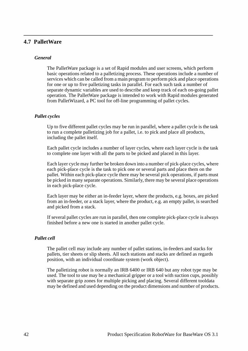
4.7 PalletWare
General
The PalletWare package is a set of Rapid modules and user screens, which perform basic operations related to a palletizing process. These operations include a number of services which can be called from a main program to perform pick and place operations for one or up to five palletizing tasks in parallel. For each such task a number of separate dynamic variables are used to describe and keep track of each on-going pallet operation. The PalletWare package is intended to work with Rapid modules generated from PalletWizard, a PC tool for off-line programming of pallet cycles.
Pallet cycles
Up to five different pallet cycles may be run in parallel, where a pallet cycle is the task to run a complete palletizing job for a pallet, i.e. to pick and place all products, including the pallet itself.
Each pallet cycle includes a number of layer cycles, where each layer cycle is the task to complete one layer with all the parts to be picked and placed in this layer.
Each layer cycle may further be broken down into a number of pick-place cycles, where each pick-place cycle is the task to pick one or several parts and place them on the pallet. Within each pick-place cycle there may be several pick operations, if parts must be picked in many separate operations. Similarly, there may be several place operations in each pick-place cycle.
Each layer may be either an in-feeder layer, where the products, e.g. boxes, are picked from an in-feeder, or a stack layer, where the product, e.g. an empty pallet, is searched and picked from a stack.
If several pallet cycles are run in parallel, then one complete pick-place cycle is always finished before a new one is started in another pallet cycle.
Pallet cell
The pallet cell may include any number of pallet stations, in-feeders and stacks for pallets, tier sheets or slip sheets. All such stations and stacks are defined as regards position, with an individual coordinate system (work object).
The palletizing robot is normally an IRB 6400 or IRB 640 but any robot type may be used. The tool to use may be a mechanical gripper or a tool with suction cups, possibly with separate grip zones for multiple picking and placing. Several different tooldata may be defined and used depending on the product dimensions and number of products.
42 Product Specification RobotWare for BaseWare OS 3.1

Products
Any number of different products with different dimensions may be handled and placed in different patterns on the pallet. Each layer must have the same product only, but different layers on a pallet may have different products.
Products may be delivered on one or several in-feeders and placed on one or several different pallets.
For each separate product individual handling speeds and load data are used.
The dimensions and speeds of the products may be changed in run time, thus affecting all pick and place positions.
Movements, approach and retreat positions
All movements are calculated in run time and relative to the different coordinate systems defined for each station. Between stations, e.g. moving from an in-feeder to a pallet station, the robot may be forced to move up to safety height and to retract before moving towards the new station. While moving to the pick or place position, the robot will first move to an approach position and then to a prepick/place position. These horizontal and vertical distances for the approach positions, relative to the pick or place position, may be individually defined per product or station. In addition, the approach direction may be individually defined per pick or place position. These approach data may be changed in run time.
The picking and placing movements and the sequence to search different stacks for empty pallets or tier sheets may be customised if necessary.
User routines
A number of different user routines may be called at certain phases of the pallet cycle. These routines can be used for communication with external equipment, for error checking, for operator messages etc. Such user routines are grouped in three main groups according to when they are called in the pallet cycle. The groups are:
- Cycle routines, connected to the different cycles, i.e. pallet cycle, layer cycle, pick and place cycle. Each such cycle may have its own individual user routine at the beginning, at the middle and at the end of the cycle.
- Station access routines, connected to the different stations. A specific user rou-tine may be called before (station-in routine) and after (station-out) a pick/place on a feeder or pallet station, e.g. to order the next products on the feeder.
- Pick stack routines, connected to stacks. Such routines are called to search and pick a product on the stack.
Product Specification RobotWare for BaseWare OS 3.1 43
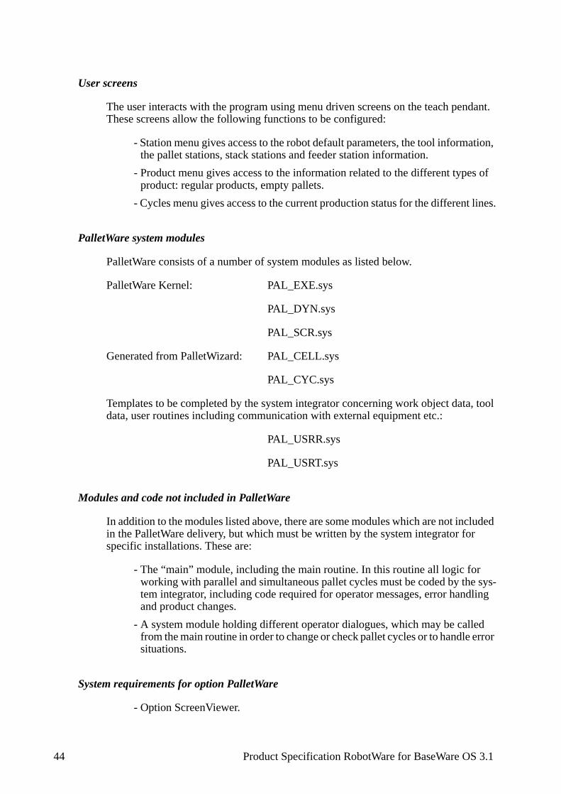
sys-ling
d error
User screens
The user interacts with the program using menu driven screens on the teach pendant. These screens allow the following functions to be configured:
- Station menu gives access to the robot default parameters, the tool information, the pallet stations, stack stations and feeder station information.
- Product menu gives access to the information related to the different types of product: regular products, empty pallets.
- Cycles menu gives access to the current production status for the different lines.
PalletWare system modules
PalletWare consists of a number of system modules as listed below.
PalletWare Kernel: PAL_EXE.sys
PAL_DYN.sys
PAL_SCR.sys
Generated from PalletWizard: PAL_CELL.sys
PAL_CYC.sys
Templates to be completed by the system integrator concerning work object data, tool data, user routines including communication with external equipment etc.:
PAL_USRR.sys
PAL_USRT.sys
Modules and code not included in PalletWare
In addition to the modules listed above, there are some modules which are not included in the PalletWare delivery, but which must be written by the system integrator for specific installations. These are:
- The “main” module, including the main routine. In this routine all logic for working with parallel and simultaneous pallet cycles must be coded by thetem integrator, including code required for operator messages, error handand product changes.
- A system module holding different operator dialogues, which may be callefrom the main routine in order to change or check pallet cycles or to handle situations.
System requirements for option PalletWare
- Option ScreenViewer.
44 Product Specification RobotWare for BaseWare OS 3.1
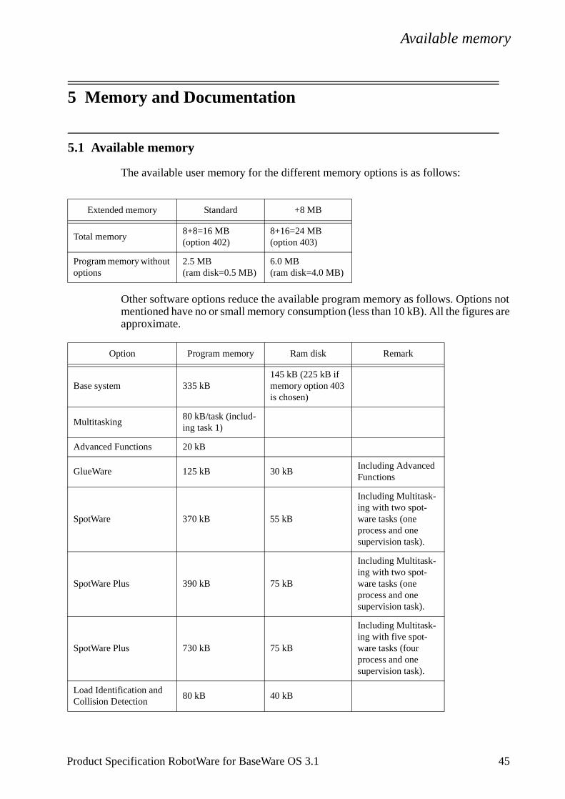
Available memory
5 Memory and Documentation
5.1 Available memory
The available user memory for the different memory options is as follows:
Other software options reduce the available program memory as follows. Options not mentioned have no or small memory consumption (less than 10 kB). All the figures are approximate.
Extended memory Standard +8 MB
Total memory8+8=16 MB(option 402)
8+16=24 MB(option 403)
Program memory without options
2.5 MB(ram disk=0.5 MB)
6.0 MB(ram disk=4.0 MB)
Option Program memory Ram disk Remark
Base system 335 kB145 kB (225 kB if memory option 403 is chosen)
Multitasking80 kB/task (includ-ing task 1)
Advanced Functions 20 kB
GlueWare 125 kB 30 kBIncluding Advanced Functions
SpotWare 370 kB 55 kB
Including Multitask-ing with two spot-ware tasks (one process and one supervision task).
SpotWare Plus 390 kB 75 kB
Including Multitask-ing with two spot-ware tasks (one process and one supervision task).
SpotWare Plus 730 kB 75 kB
Including Multitask-ing with five spot-ware tasks (four process and one supervision task).
Load Identification and Collision Detection
80 kB 40 kB
Product Specification RobotWare for BaseWare OS 3.1 45
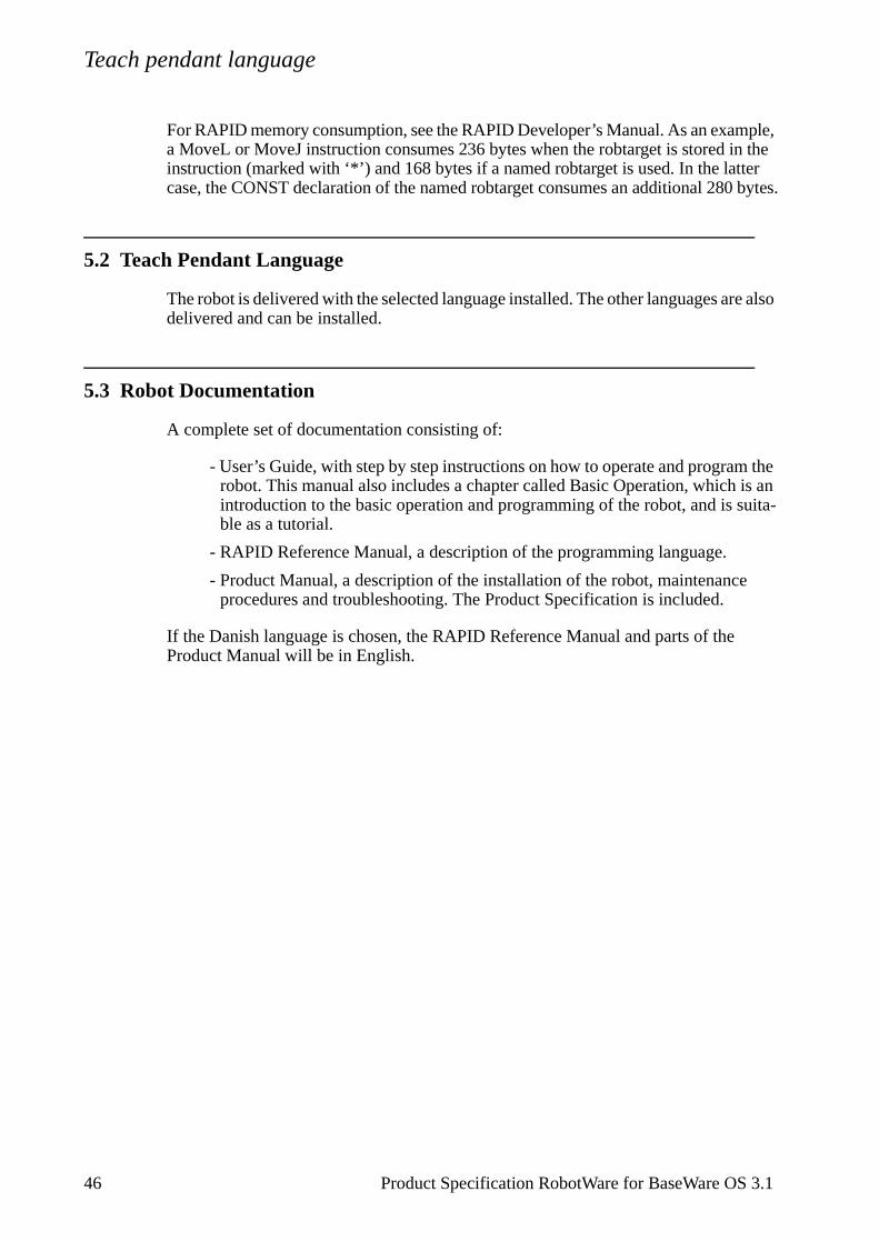
Teach pendant language
ple, n the er bytes.
re also
the is an uita-
For RAPID memory consumption, see the RAPID Developer’s Manual. As an exama MoveL or MoveJ instruction consumes 236 bytes when the robtarget is stored iinstruction (marked with ‘*’) and 168 bytes if a named robtarget is used. In the lattcase, the CONST declaration of the named robtarget consumes an additional 280
5.2 Teach Pendant Language
The robot is delivered with the selected language installed. The other languages adelivered and can be installed.
5.3 Robot Documentation
A complete set of documentation consisting of:
- User’s Guide, with step by step instructions on how to operate and programrobot. This manual also includes a chapter called Basic Operation, which introduction to the basic operation and programming of the robot, and is sble as a tutorial.
- RAPID Reference Manual, a description of the programming language.
- Product Manual, a description of the installation of the robot, maintenanceprocedures and troubleshooting. The Product Specification is included.
If the Danish language is chosen, the RAPID Reference Manual and parts of theProduct Manual will be in English.
46 Product Specification RobotWare for BaseWare OS 3.1
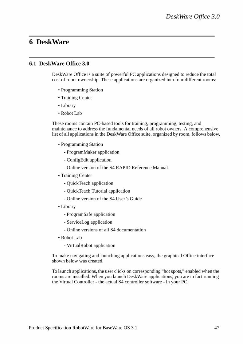
DeskWare Office 3.0
nsive low.
ce
n the ning
6 DeskWare
6.1 DeskWare Office 3.0
DeskWare Office is a suite of powerful PC applications designed to reduce the total cost of robot ownership. These applications are organized into four different rooms:
• Programming Station
• Training Center
• Library
• Robot Lab
These rooms contain PC-based tools for training, programming, testing, and maintenance to address the fundamental needs of all robot owners. A comprehelist of all applications in the DeskWare Office suite, organized by room, follows be
• Programming Station
- ProgramMaker application
- ConfigEdit application
- Online version of the S4 RAPID Reference Manual
• Training Center
- QuickTeach application
- QuickTeach Tutorial application
- Online version of the S4 User’s Guide
• Library
- ProgramSafe application
- ServiceLog application
- Online versions of all S4 documentation
• Robot Lab
- VirtualRobot application
To make navigating and launching applications easy, the graphical Office interfashown below was created.
To launch applications, the user clicks on corresponding “hot spots,” enabled wherooms are installed. When you launch DeskWare applications, you are in fact runthe Virtual Controller - the actual S4 controller software - in your PC.
Product Specification RobotWare for BaseWare OS 3.1 47
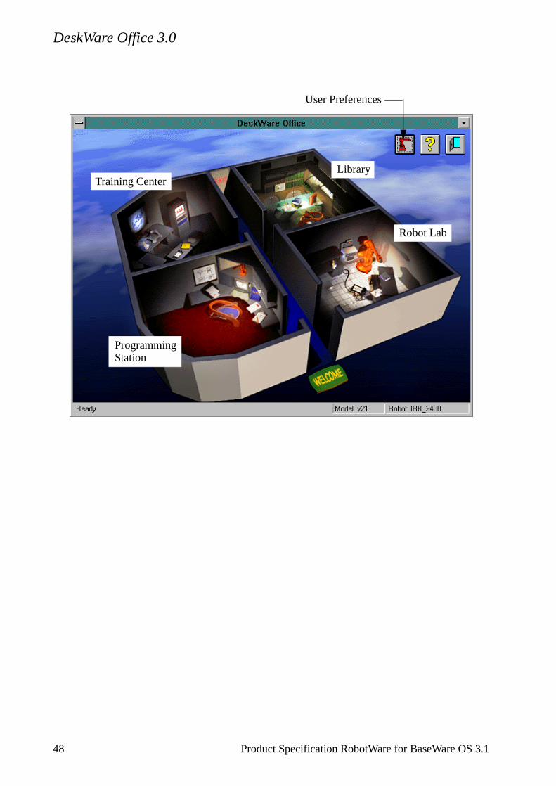
DeskWare Office 3.0
User Preferences
LibraryTraining Center
ProgrammingStation
Robot Lab
48 Product Specification RobotWare for BaseWare OS 3.1
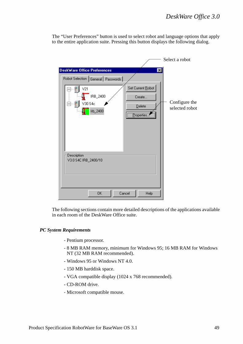
DeskWare Office 3.0
apply
lable
The “User Preferences” button is used to select robot and language options thatto the entire application suite. Pressing this button displays the following dialog.
The following sections contain more detailed descriptions of the applications avaiin each room of the DeskWare Office suite.
PC System Requirements
- Pentium processor.
- 8 MB RAM memory, minimum for Windows 95; 16 MB RAM for Windows NT (32 MB RAM recommended).
- Windows 95 or Windows NT 4.0.
- 150 MB harddisk space.
- VGA compatible display (1024 x 768 recommended).
- CD-ROM drive.
- Microsoft compatible mouse.
Select a robot
Configure theselected robot
Product Specification RobotWare for BaseWare OS 3.1 49
Programming Station 3.0
6.2 Programming Station 3.0
Programming Station is a collection of software applications that assist the user in constructing and editing robot programs and configuration files on a PC.
Programming Station includes:
- ProgramMaker application.
- ConfigEdit application.
- Online version of the S4 RAPID Reference Manual.
ProgramMaker allows the user to create and edit robot programs on a PC, in the Windows environment.
ProgramMaker is a complete system for creating and editing RAPID programs for the S4 robot controller. ProgramMaker is unique, compared to other offline programming systems, as it embeds the functionality of the S4 robot controller and uses this capability to perform all robot controller-specific tasks. For example, you can configure the embedded S4 controller within ProgramMaker so that it represents the same I/O setup as your real robot. Then, when you program I/O-based statements, ProgramMaker checks to ensure that you refer only to those signals that are defined on your robot.
ProgramMaker can assume the functionality of different versions of the S4 controller, for example, V2.1 or V3.0, and behave in accordance with the features specific to that version of controller. This means you can see the same status and error messages in ProgramMaker as you see on the real robot.
ProgramMaker implements an advanced Windows user interface that permits you to develop RAPID programs quickly, easily, and without error. Unlike using a conventional text editor, ProgramMaker helps you write RAPID programs by creating instructions with a single command, providing default parameters in many cases automatically. For beginning programmers, ProgramMaker provides instruction-sensitive dialogs that make programming complex statements easy. For experts, ProgramMaker also offers the more conventional approach of text-based entry of RAPID program statements. Using either method, ProgramMaker guarantees that your programs will be valid when you load them into your robot.
You can set up ProgramMaker to assume the configuration of a specific robot controller. You do this using the Preferences dialog of Office. Configuration includes, for example, the specific version (V2.1, V3.0, etc.) of the robot controller, the software options installed on that controller (ArcWare, SpotWare, Serial RAP, etc.), and the amount of memory installed (10MB, 12MB, etc.). The Preferences dialog can be used to select a predefined configuration, or it can be used to create entirely new configurations through user-assisted dialogs or through direct import from the floppy disks shipped with your robot.
The following image illustrates some of the main features of the ProgramMaker user interface.
50 Product Specification RobotWare for BaseWare OS 3.1
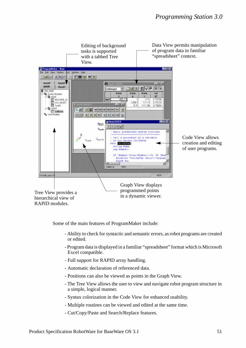
Programming Station 3.0
soft
re in
Some of the main features of ProgramMaker include:
- Ability to check for syntactic and semantic errors, as robot programs are created or edited.
- Program data is displayed in a familiar “spreadsheet” format which is MicroExcel compatible.
- Full support for RAPID array handling.
- Automatic declaration of referenced data.
- Positions can also be viewed as points in the Graph View.
- The Tree View allows the user to view and navigate robot program structua simple, logical manner.
- Syntax colorization in the Code View for enhanced usability.
- Multiple routines can be viewed and edited at the same time.
- Cut/Copy/Paste and Search/Replace features.
Data View permits manipulationof program data in familiar
Editing of backgroundtasks is supported with a tabbed Tree
Tree View provides ahierarchical view ofRAPID modules.
Graph View displaysprogrammed pointsin a dynamic viewer.
Code View allowscreation and editingof user programs.
“spreadsheet” context.View.
Product Specification RobotWare for BaseWare OS 3.1 51
Programming Station 3.0
ols’
layout ols,
t ducts allets
PalletWizard is a programming tool used for palletizing applications. It must be used in combination with PalletWare (i.e. the output generated from PalletWizard is used in conjunction with PalletWare).
PalletWizard is an integrated component of ProgramMaker, invoked from the ‘Tomenu.
PalletWizard allows the user to create and edit system modules, which define the of a palletizing robot cell with its different pallet stations, infeeders, stacks and toincluding the pallet composition (products, layers and layer patterns).
A robot cell for palletizing incorporates one palletizing robot, one or several pallestations where products are placed and one or several infeeders, from which proare picked. The cell may also include one or several stacks, from which empty por tier sheets are drawn.
Objects in a palletizing cell
The following objects and properties for a palletizing cell may be defined using PalletWizard:
• Robot
- Speed without products
- Acceleration without products
• Pallet StationsSeveral pallet stations may be defined, each with the following properties
- Maximum and minimum height
- Approach height
• InfeedersSeveral infeeders may be defined, each with the following properties
- Maximum and minimum height
- Approach height
- Product alignment
- Type of product
• StacksSeveral stacks may be defined, each with the following properties
- Maximum and minimum height
- Approach height
- Product alignment
- Type of product
52 Product Specification RobotWare for BaseWare OS 3.1
Programming Station 3.0
may
let
f one
here n the
s
ese llet
d to ines g out.
• ProductsA number of different products, for example, boxes, pallets, tier sheets etc., be defined, each with the following properties:
- Size
- Sides with labels
- Robot speed and acceleration when carrying the product
- Pick and place approach distances, vertically and horizontally
Pallet cycles
A number of different pallet cycles may be defined. A pallet cycle consists of palletizing a complete pallet (i.e. to pick and place all products, including the palitself).
Each pallet cycle includes a number of layer cycles. Each layer cycle consists ocomplete layer with all the products to be picked and placed in this layer.
Each layer cycle may further be broken down in a number of pick-place cycles, weach pick-place cycle consists of picking one or several parts and placing them opallet. Within each pick-place cycle there may be several pick operations, if partshould be picked in separate operations. Similarly, there might be several place operations in each pick-place cycle.
A number of different layer cycles may be defined, including pick-place cycles. Thlayer cycles may then be freely used and combined in different pallet cycles (pacompositions).
For each layer cycle the following properties may be defined:
- The product to pick and place.
- The infeeder to use. Several infeeders may be used, if necessary.
- The pattern to use.
- The pick-place cycles to use.
For each pattern the following properties may be defined:
- The number of parts to place.
- The position and orientation of each part. Part positions are always relatereference lines, freely positioned on the pallet. Any number of reference land positions are allowed. Label sides of the articles may be placed facin
- The envelope of the pattern (i.e. the outer borders of the pattern).
Product Specification RobotWare for BaseWare OS 3.1 53

Programming Station 3.0
For each pick-place operation the following properties may be defined:
- The number of pick operations
- The number of place operations
- The tool to be used. Different tool definitions may be used depending on the article to pick and the number of articles.
- The approach direction for pick and place operations
- The pick and place positions, related to the used pattern
For each pallet cycle the following properties may be defined:
- The pallet station to use. Several pallet stations may be used, alternately, if nec-essary.
- The pallet to use in the first layer.
- Orientation of the pallet in the pallet station
- Load alignment (i.e. alignment of the pattern envelope - front, center or back, left, center or right).
- The pallet composition for a complete pallet (i.e. specification of layer cycles to use in each layer).
User routines
It is possible to call different user routines in different phases of the pallet cycle. These user routines may be used for installation specific tasks, for example, communication with external equipment, operator messages, intermediate positions, etc. In PalletWizard, only the declarations of these user routines are created. The routine body, or RAPID code, can then be completed within ProgramMaker.
All routines are grouped in three main categories, according to when they are called in the pallet cycle. The groups are:
- Cycle routines, connected to the different cycles (pallet cycle, layer cycle, pick and place cycle). Each such cycle may have its own individual user routine in the beginning, in the middle, and at the end of the cycle.
- Station access routines, connected to the different stations. A specific user rou-tine may be called before (station-in routine) and after (station-out) a pick/place action on a feeder or pallet station, for example, to order the next products on the feeder.
- Pick stack routines, connected to stacks. Such routines are called to search and pick a product on the stack.
Load data
Load data (load, center of gravity, and moment of inertia) is automatically set up by PalletWizard depending on the article dimensions, weight and number of articles in the tool.
54 Product Specification RobotWare for BaseWare OS 3.1
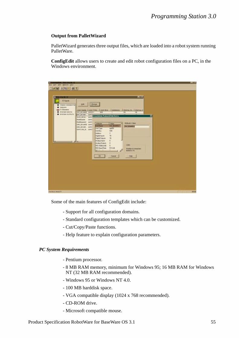
Programming Station 3.0
Output from PalletWizard
PalletWizard generates three output files, which are loaded into a robot system running PalletWare.
ConfigEdit allows users to create and edit robot configuration files on a PC, in the Windows environment.
Some of the main features of ConfigEdit include:
- Support for all configuration domains.
- Standard configuration templates which can be customized.
- Cut/Copy/Paste functions.
- Help feature to explain configuration parameters.
PC System Requirements
- Pentium processor.
- 8 MB RAM memory, minimum for Windows 95; 16 MB RAM for Windows NT (32 MB RAM recommended).
- Windows 95 or Windows NT 4.0.
- 100 MB harddisk space.
- VGA compatible display (1024 x 768 recommended).
- CD-ROM drive.
- Microsoft compatible mouse.
Product Specification RobotWare for BaseWare OS 3.1 55
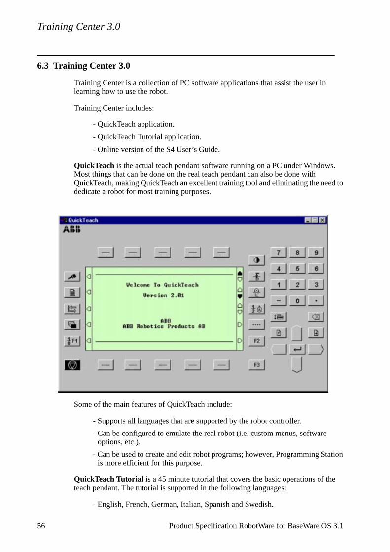
Training Center 3.0
s.
ed to
tation
e
6.3 Training Center 3.0
Training Center is a collection of PC software applications that assist the user in learning how to use the robot.
Training Center includes:
- QuickTeach application.
- QuickTeach Tutorial application.
- Online version of the S4 User’s Guide.
QuickTeach is the actual teach pendant software running on a PC under WindowMost things that can be done on the real teach pendant can also be done with QuickTeach, making QuickTeach an excellent training tool and eliminating the nededicate a robot for most training purposes.
Some of the main features of QuickTeach include:
- Supports all languages that are supported by the robot controller.
- Can be configured to emulate the real robot (i.e. custom menus, softwareoptions, etc.).
- Can be used to create and edit robot programs; however, Programming Sis more efficient for this purpose.
QuickTeach Tutorial is a 45 minute tutorial that covers the basic operations of thteach pendant. The tutorial is supported in the following languages:
- English, French, German, Italian, Spanish and Swedish.
56 Product Specification RobotWare for BaseWare OS 3.1

Training Center 3.0
PC System Requirements
- Pentium processor.
- 8 MB RAM memory, minimum for Windows 95; 16 MB RAM for Windows NT (32 MB RAM recommended).
- Windows 95 or Windows NT 4.0.
- 100 MB harddisk space.
- VGA compatible display (1024 x 768 recommended).
- CD-ROM drive.
- Microsoft compatible mouse.
Product Specification RobotWare for BaseWare OS 3.1 57
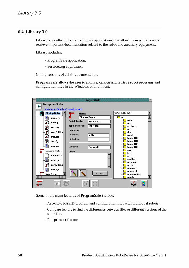
Library 3.0
6.4 Library 3.0
Library is a collection of PC software applications that allow the user to store and retrieve important documentation related to the robot and auxiliary equipment.
Library includes:
- ProgramSafe application.
- ServiceLog application.
Online versions of all S4 documentation.
ProgramSafe allows the user to archive, catalog and retrieve robot programs and configuration files in the Windows environment.
Some of the main features of ProgramSafe include:
- Associate RAPID program and configuration files with individual robots.
- Compare feature to find the differences between files or different versions of the same file.
- File printout feature.
58 Product Specification RobotWare for BaseWare OS 3.1
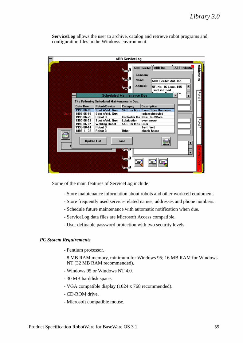
Library 3.0
ServiceLog allows the user to archive, catalog and retrieve robot programs and configuration files in the Windows environment.
Some of the main features of ServiceLog include:
- Store maintenance information about robots and other workcell equipment.
- Store frequently used service-related names, addresses and phone numbers.
- Schedule future maintenance with automatic notification when due.
- ServiceLog data files are Microsoft Access compatible.
- User definable password protection with two security levels.
PC System Requirements
- Pentium processor.
- 8 MB RAM memory, minimum for Windows 95; 16 MB RAM for Windows NT (32 MB RAM recommended).
- Windows 95 or Windows NT 4.0.
- 30 MB harddisk space.
- VGA compatible display (1024 x 768 recommended).
- CD-ROM drive.
- Microsoft compatible mouse.
Product Specification RobotWare for BaseWare OS 3.1 59
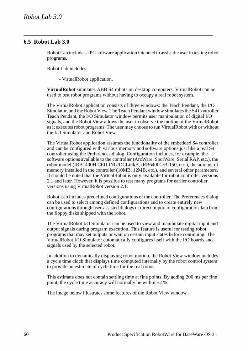
Robot Lab 3.0
6.5 Robot Lab 3.0
Robot Lab includes a PC software application intended to assist the user in testing robot programs.
Robot Lab includes:
- VirtualRobot application.
VirtualRobot simulates ABB S4 robots on desktop computers. VirtualRobot can be used to test robot programs without having to occupy a real robot system.
The VirtualRobot application consists of three windows: the Teach Pendant, the I/O Simulator, and the Robot View. The Teach Pendant window simulates the S4 Controller Teach Pendant, the I/O Simulator window permits user manipulation of digital I/O signals, and the Robot View allows the user to observe the motion of the VirtualRobot as it executes robot programs. The user may choose to run VirtualRobot with or without the I/O Simulator and Robot View.
The VirtualRobot application assumes the functionality of the embedded S4 controller and can be configured with various memory and software options just like a real S4 controller using the Preferences dialog. Configuration includes, for example, the software options available to the controller (ArcWare, SpotWare, Serial RAP, etc.), the robot model (IRB1400H CEILING/DCLinkB, IRB6400C/B-150, etc.), the amount of memory installed in the controller (10MB, 12MB, etc.), and several other parameters. It should be noted that the VirtualRobot is only available for robot controller versions 2.1 and later. However, it is possible to test many programs for earlier controller versions using VirtualRobot version 2.1.
Robot Lab includes predefined configurations of the controller. The Preferences dialog can be used to select among defined configurations and to create entirely new configurations through user-assisted dialogs or direct import of configuration data from the floppy disks shipped with the robot.
The VirtualRobot I/O Simulator can be used to view and manipulate digital input and output signals during program execution. This feature is useful for testing robot programs that may set outputs or wait on certain input states before continuing. The VirtualRobot I/O Simulator automatically configures itself with the I/O boards and signals used by the selected robot.
In addition to dynamically displaying robot motion, the Robot View window includes a cycle time clock that displays time computed internally by the robot control system to provide an estimate of cycle time for the real robot.
This estimate does not contain settling time at fine points. By adding 200 ms per fine point, the cycle time accuracy will normally be within ±2 %.
The image below illustrates some features of the Robot View window.
60 Product Specification RobotWare for BaseWare OS 3.1
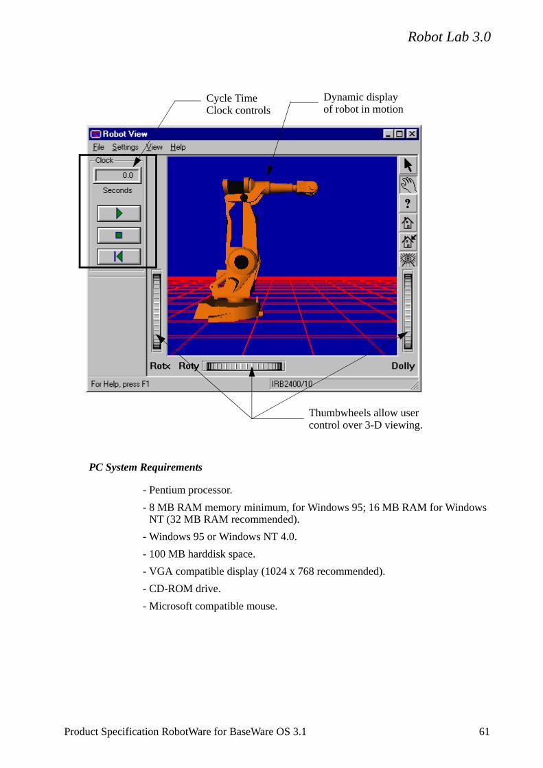
Robot Lab 3.0
PC System Requirements
- Pentium processor.
- 8 MB RAM memory minimum, for Windows 95; 16 MB RAM for Windows NT (32 MB RAM recommended).
- Windows 95 or Windows NT 4.0.
- 100 MB harddisk space.
- VGA compatible display (1024 x 768 recommended).
- CD-ROM drive.
- Microsoft compatible mouse.
Dynamic displayof robot in motion
Cycle TimeClock controls
Thumbwheels allow usercontrol over 3-D viewing.
Product Specification RobotWare for BaseWare OS 3.1 61

Robot Lab 3.0
62 Product Specification RobotWare for BaseWare OS 3.1
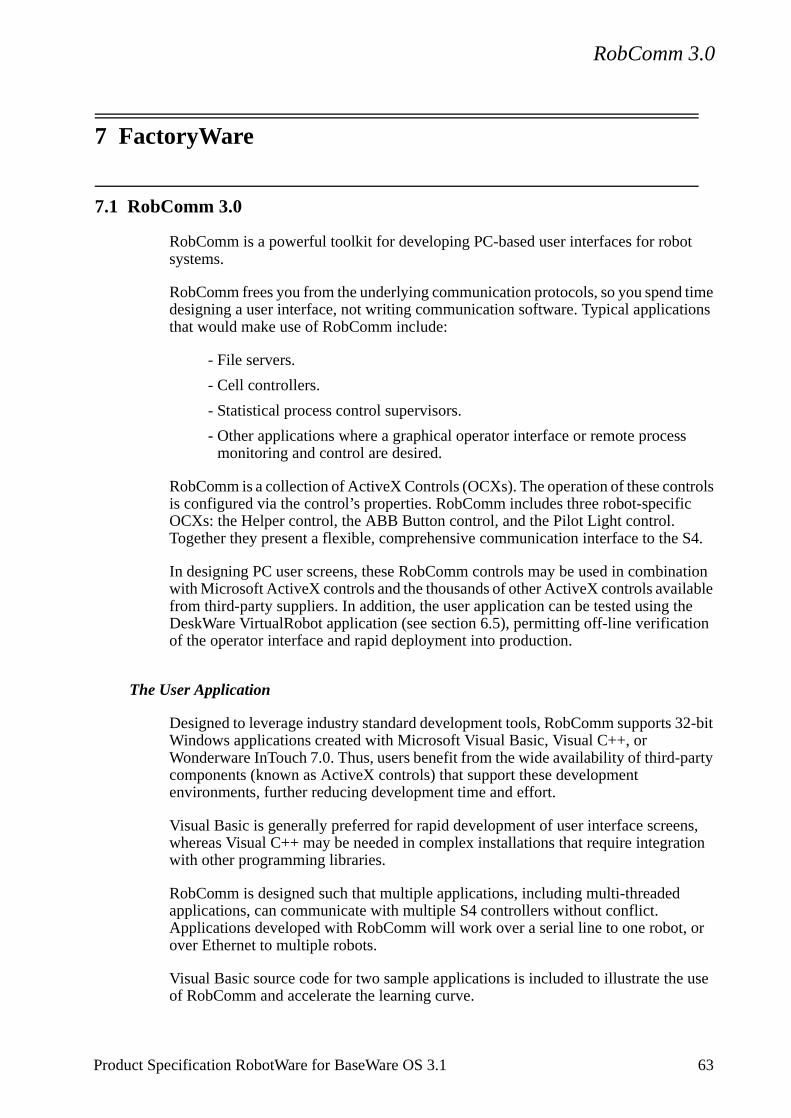
RobComm 3.0
c
S4.
ation ble e
on
32-bit
arty
ns, tion
or
use
7 FactoryWare
7.1 RobComm 3.0
RobComm is a powerful toolkit for developing PC-based user interfaces for robot systems.
RobComm frees you from the underlying communication protocols, so you spend time designing a user interface, not writing communication software. Typical applications that would make use of RobComm include:
- File servers.
- Cell controllers.
- Statistical process control supervisors.
- Other applications where a graphical operator interface or remote process monitoring and control are desired.
RobComm is a collection of ActiveX Controls (OCXs). The operation of these controls is configured via the control’s properties. RobComm includes three robot-specifiOCXs: the Helper control, the ABB Button control, and the Pilot Light control. Together they present a flexible, comprehensive communication interface to the
In designing PC user screens, these RobComm controls may be used in combinwith Microsoft ActiveX controls and the thousands of other ActiveX controls availafrom third-party suppliers. In addition, the user application can be tested using thDeskWare VirtualRobot application (see section 6.5), permitting off-line verificatiof the operator interface and rapid deployment into production.
The User Application
Designed to leverage industry standard development tools, RobComm supports Windows applications created with Microsoft Visual Basic, Visual C++, or Wonderware InTouch 7.0. Thus, users benefit from the wide availability of third-pcomponents (known as ActiveX controls) that support these development environments, further reducing development time and effort.
Visual Basic is generally preferred for rapid development of user interface screewhereas Visual C++ may be needed in complex installations that require integrawith other programming libraries.
RobComm is designed such that multiple applications, including multi-threaded applications, can communicate with multiple S4 controllers without conflict. Applications developed with RobComm will work over a serial line to one robot, over Ethernet to multiple robots.
Visual Basic source code for two sample applications is included to illustrate theof RobComm and accelerate the learning curve.
Product Specification RobotWare for BaseWare OS 3.1 63
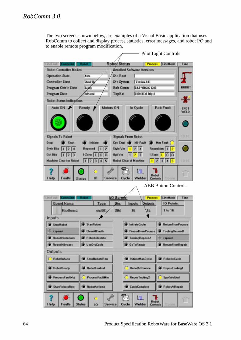
RobComm 3.0
The two screens shown below, are examples of a Visual Basic application that uses RobComm to collect and display process statistics, error messages, and robot I/O and to enable remote program modification.
Pilot Light Controls
ABB Button Controls
64 Product Specification RobotWare for BaseWare OS 3.1

RobComm 3.0
Following is a brief description of each ActiveX control included the RobComm toolkit.
The Helper Control
This is the primary communication interface for RobComm. The Helper control is an invisible control that provides methods, properties, and events to expose the entire S4 communication interface.
The ABB Button Control
The ABB Button control is a derivative of the standard Windows button control. An ABB Button can be connected directly to a specific digital I/O signal in an S4 control. The Button control provides a simple way to view and modify a digital signal, and, in most cases, can be used without adding code to your application.
The display of the button can be configured via property settings to automatically update itself based on the current state of the communication link to the robot control and the state of the digital signal assigned to the button control. Optionally, you can display bitmaps, text strings, text colors, and/or background colors based on the signal state (on or off). The button action can be configured to turn a signal on, turn a signal off, toggle a signal, pulse a signal, or do nothing in response to a mouse click.
The Pilot Light Control
The Pilot Light control tracks the state of a specific digital signal. This control is configured via properties and requires no additional code.
The display of the Pilot Light is modeled after status lamps commonly used in hard-wired operator panels. The Pilot Light displays bitmaps to represent the on and off states of the associated signal. The user selects the on and off colors via properties. A Caption Property is used to label the Pilot Light.
When the communication link to the robot control is down, the Pilot Light automatically disables itself and re-enables itself when the communication link is restored.
PC System Requirements
- Pentium processor.
- 8 MB RAM memory minimum for Windows 95, 16 MB RAM for Windows NT (32 MB RAM recommended).
- Windows 95 or Windows NT 4.0.
- Microsoft Visual Basic, Visual C++, or Wonderware InTouch 7.0 (for applica-tion development).
- 20 MB free hard disk space.
- VGA compatible display (1024 x 768 recommended).
Product Specification RobotWare for BaseWare OS 3.1 65
RobComm 3.0
- CD-ROM drive.
- One or more network interfaces - any NDIS or ODI network adapter (for ether-net) or a serial port (for serial connection to one S4).
- A terminal server with SLIP protocol support is required for connections to mul-tiple S4 controllers not equipped with an ethernet interface.
- Microsoft compatible mouse.
Robot Controller Requirements
- FactoryWare Interface (or RAP communication) installed. FactoryWare Inter-face is preferred as RAP communication requires run-time licensing on the PC.
- Ethernet interface hardware (optional).
- RobComm 3.0 can be used with all versions of BaseWare OS.
66 Product Specification RobotWare for BaseWare OS 3.1

RobView 3.1
7.2 RobView 3.1
RobView is an end-user application that lets the customer visualise robot data in a PC. It also lets the user remotely operate robots from a PC and provides access to robot files for simple file transfer and back-up. RobView is Windows-based and easy to use.
RobView comes as a ready to use application and is typically run in a PC on the factory floor, connected to one or more robots. RobView takes care of the PC to robot communication. The user can start working immediately, using the pre-defined features and buttons. He can also define his own buttons and signals.
A built-in user security system can be used to prevent accidental use by unauthorized persons.
Pre-defined controls
In RobView there are several pre-defined objects. They are configured for the user to operate robots, look at various robot status and perform file operations. Each robot is represented by a small robot-box on the screen.
Product Specification RobotWare for BaseWare OS 3.1 67
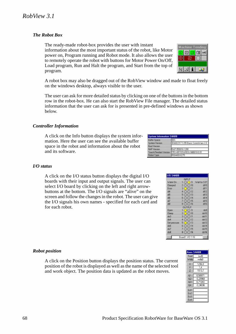
RobView 3.1
The Robot Box
The ready-made robot-box provides the user with instant information about the most important status of the robot, like Motor power on, Program running and Robot mode. It also allows the user to remotely operate the robot with buttons for Motor Power On/Off, Load program, Run and Halt the program, and Start from the top of program.
A robot box may also be dragged out of the RobView window and made to float freely on the windows desktop, always visible to the user.
The user can ask for more detailed status by clicking on one of the buttons in the bottom row in the robot-box. He can also start the RobView File manager. The detailed status information that the user can ask for is presented in pre-defined windows as shown below.
Controller Information
A click on the Info button displays the system infor-mation. Here the user can see the available buffer space in the robot and information about the robot and its software.
I/O status
A click on the I/O status button displays the digital I/O boards with their input and output signals. The user can select I/O board by clicking on the left and right arrow-buttons at the bottom. The I/O signals are “alive” on the screen and follow the changes in the robot. The user can give the I/O signals his own names - specified for each card and for each robot.
Robot position
A click on the Position button displays the position status. The current position of the robot is displayed as well as the name of the selected tool and work object. The position data is updated as the robot moves.
68 Product Specification RobotWare for BaseWare OS 3.1
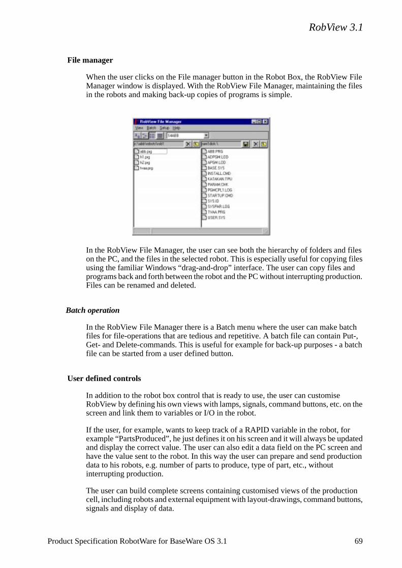
RobView 3.1
d ction.
atch ut-, batch
the
dated en and uction
tion tons,
File manager
When the user clicks on the File manager button in the Robot Box, the RobView File Manager window is displayed. With the RobView File Manager, maintaining the files in the robots and making back-up copies of programs is simple.
In the RobView File Manager, the user can see both the hierarchy of folders and files on the PC, and the files in the selected robot. This is especially useful for copying files using the familiar Windows “drag-and-drop” interface. The user can copy files anprograms back and forth between the robot and the PC without interrupting produFiles can be renamed and deleted.
Batch operation
In the RobView File Manager there is a Batch menu where the user can make bfiles for file-operations that are tedious and repetitive. A batch file can contain PGet- and Delete-commands. This is useful for example for back-up purposes - a file can be started from a user defined button.
User defined controls
In addition to the robot box control that is ready to use, the user can customise RobView by defining his own views with lamps, signals, command buttons, etc. onscreen and link them to variables or I/O in the robot.
If the user, for example, wants to keep track of a RAPID variable in the robot, forexample “PartsProduced”, he just defines it on his screen and it will always be upand display the correct value. The user can also edit a data field on the PC screhave the value sent to the robot. In this way the user can prepare and send proddata to his robots, e.g. number of parts to produce, type of part, etc., without interrupting production.
The user can build complete screens containing customised views of the produccell, including robots and external equipment with layout-drawings, command butsignals and display of data.
Product Specification RobotWare for BaseWare OS 3.1 69
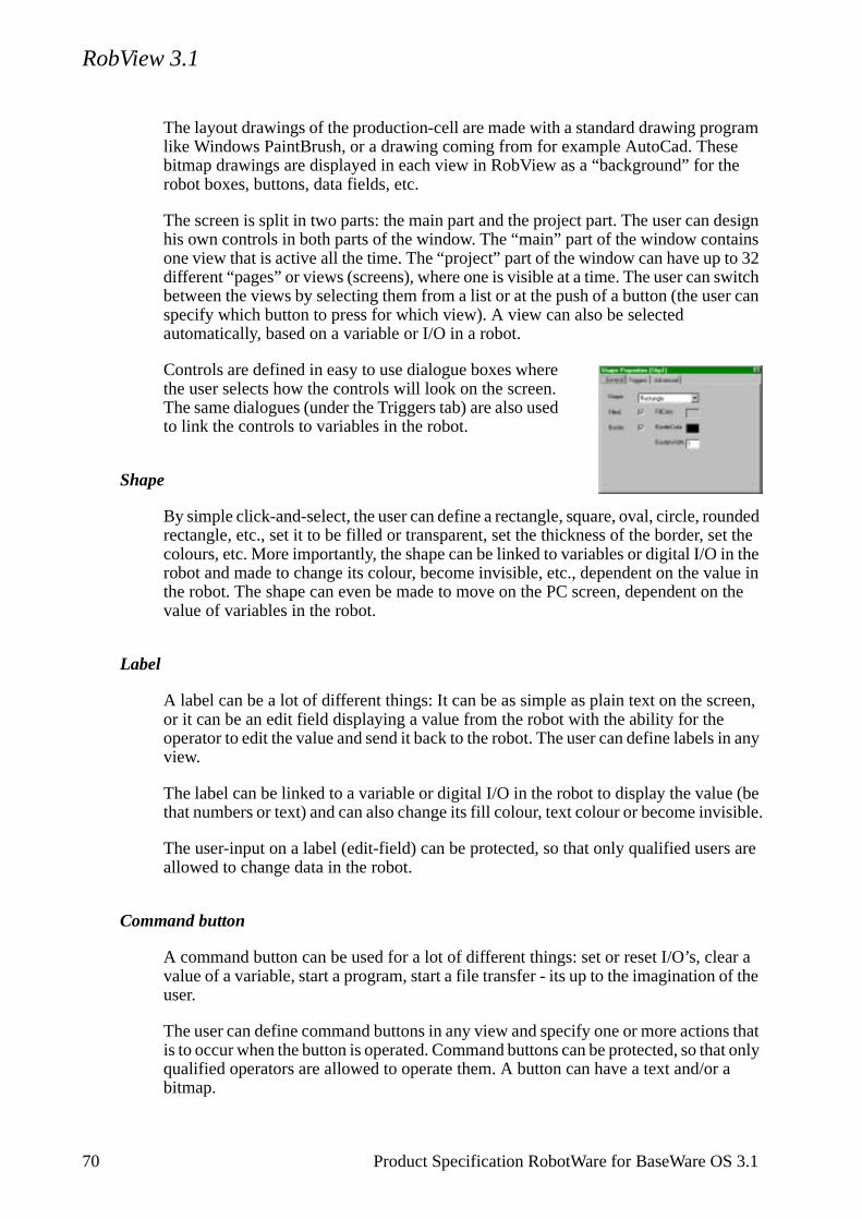
RobView 3.1
e
esign ins
o 32 witch er can
unded et the n the lue in n the
reen,
in any
(be isible.
s are
ar a f the
s that at only a
The layout drawings of the production-cell are made with a standard drawing program like Windows PaintBrush, or a drawing coming from for example AutoCad. These bitmap drawings are displayed in each view in RobView as a “background” for throbot boxes, buttons, data fields, etc.
The screen is split in two parts: the main part and the project part. The user can dhis own controls in both parts of the window. The “main” part of the window contaone view that is active all the time. The “project” part of the window can have up tdifferent “pages” or views (screens), where one is visible at a time. The user can sbetween the views by selecting them from a list or at the push of a button (the usspecify which button to press for which view). A view can also be selected automatically, based on a variable or I/O in a robot.
Controls are defined in easy to use dialogue boxes where the user selects how the controls will look on the screen. The same dialogues (under the Triggers tab) are also used to link the controls to variables in the robot.
Shape
By simple click-and-select, the user can define a rectangle, square, oval, circle, rorectangle, etc., set it to be filled or transparent, set the thickness of the border, scolours, etc. More importantly, the shape can be linked to variables or digital I/O irobot and made to change its colour, become invisible, etc., dependent on the vathe robot. The shape can even be made to move on the PC screen, dependent ovalue of variables in the robot.
Label
A label can be a lot of different things: It can be as simple as plain text on the scor it can be an edit field displaying a value from the robot with the ability for the operator to edit the value and send it back to the robot. The user can define labelsview.
The label can be linked to a variable or digital I/O in the robot to display the valuethat numbers or text) and can also change its fill colour, text colour or become inv
The user-input on a label (edit-field) can be protected, so that only qualified userallowed to change data in the robot.
Command button
A command button can be used for a lot of different things: set or reset I/O’s, clevalue of a variable, start a program, start a file transfer - its up to the imagination ouser.
The user can define command buttons in any view and specify one or more actionis to occur when the button is operated. Command buttons can be protected, so thqualified operators are allowed to operate them. A button can have a text and/orbitmap.
70 Product Specification RobotWare for BaseWare OS 3.1
RobView 3.1
In addition, also a button can be linked to variables or I/O in the robot and made to change its bitmap picture, the colour of the text or become invisible, dependent on the value in the robot.
Grid
A grid can be connected to both complex variables or arrays. It will dynamically updated the data field displaying the value of a robot variable, and has the ability to edit the value and send it back to the robot.
The user can define grids in any view. It is easy to set the size of the grid from the Grid property page. You may also define column and row header texts.
The user-input on a grid can be protected, so that only qualified users are allowed to change data in the robot.
Icon
The icon control is used for drawing a picture on any of the views. The picture files are typically bitmap files (.bmp) or icon (.ico) files that you for example have prepared with the Windows Paint application, or have exported from some other drawing program. The icon can be linked to a variable or digital I/O in the robot and made to change picture or become invisible dependent on the value of the robot variable.
Hot-Spot
Select the Hot-spot control to draw a hot-spot in any of the views. It is usually placed on top of other controls (e.g. Icon), to make RobView change view when you click on the hot-spot. The hot-spot is invisible in run mode.
Peripheral equipment
The user defined controls can also be linked to signals in peripheral equipment. This can be done in two ways: 1) By using spare I/O in the robot where signals from the peripheral equipment are connected so that RobView can reach them or 2) by using a dedicated DDE Server if one is available for the equipment in question, so that RobView can connect to the variables of that DDE Server and in this way be able to control and monitor the external equipment.
Multiple robots
RobView can be supplied with support for one or multiple robots. For use with one robot, the robot is connected directly to the serial port in the PC.
If the robots are equipped with a network option, they can be connected directly by ethernet to the networked PC.
Product Specification RobotWare for BaseWare OS 3.1 71
RobView 3.1
eded he e
ed).
For use with more than one robot with serial connections, a “terminal server” is nein the set-up. This is a box with eight or more serial ports and an ethernet port. Trobots are connected to the serial ports and the PC (with an ethernet board) to thethernet port. The “ShivaPort” from Shiva (used to be called “SpiderPort”) is an example of a good terminal server for this use.
PC System Requirements
The requirements for RobView will depend on the size of the installation and thenumber of robots. The descriptions below are recommendations only.
RobView for one robot
486 DX-66 minimum (Pentium recommended).
16 MB RAM memory or more.
10 MB free harddisk space.
Windows-95 or Windows/NT installed.
VGA compatible display (higher resolution recommended).
3.5” 1.44 MB diskette drive or CD rom.
Serial port or Network board.
RobView for multiple robots
Pentium 75 MHz (minimum).
16 MB RAM memory min. (more recommended).
10 MB free harddisk space.
Windows-95 or Windows/NT installed.
VGA compatible display (higher resolution and large screen strongly recommend
3.5” 1.44 MB diskette drive or CD rom.
Network board (e.g. 3COM EtherLink III 3C509).
Alternatively a terminal server may be used.
Robot Controller Requirements
FactoryWare Interface 3.1 (or RAP Communication 3.1) installed.
Ethernet interface hardware (optional).
RobComm 3.1 can run with all versions of BaseWare OS.
72 Product Specification RobotWare for BaseWare OS 3.1
RobView 3.1
Technical specification
Platform: IBM/Intel based PC and compatibles
Operating system: Microsoft Windows-95 or Windows/NT 4.0(not included)
TCP/IP stack: The generic Microsoft winsock.dll (not included, comes with Windows)
RPC: Public domain Sun rpc.dll, ported to Windows/NT (included)
Software protection: Access key, placed in printer port, with key-password. (Will run for five hour intervals without password or key)
User security: Optional Log In functionality with user-id and user-password. Four user levels: View, Safe, Expert and “Programmer”
Product Specification RobotWare for BaseWare OS 3.1 73
DDE Server 2.3
ts the mic
ted as ted in the
S4 s sure DDE les. If
le to
bot error
rver antly.
more e
7.3 DDE Server 2.3
The DDE Server is a software building block that provides reliable, quick and accurate flow of information between robots and a PC. This is what the user needs if he wants to build his own customised user interface, using visualisation packages like for example “InTouch” from Wonderware.
The S4 DDE Server takes care of the communication with the robot, and presendata in the industry standard DDE communication protocol. DDE stands for DynaData Exchange. It is a communication protocol designed by Microsoft to allow Windows applications to send and receive data to/from each other. It is implemena client/server mechanism. The server application (like the ABB S4 DDE Server)provides the data and accepts requests from any other application that is interesits data. An application that can “talk” the DDE “language” can communicate withABB robots via the S4 DDE Server. Examples of applications that do DDE communication are Microsoft “Excel” and “InTouch” from Wonderware.
The S4 DDE Server communicates with robots using the ABB RAP protocol. TheDDE Server maintains a database of the relevant variables in the robot and makethat these DDE variables are kept updated at all times. The application using theServer can concentrate on the user interface and rely on the updated DDE variabnew RAPID variables are introduced in the robot program, the DDE Server is abcreate corresponding DDE variables “on-the-fly”.
Functionality
The S4 DDE Server provides reading and writing of I/O, RAPID variables and rosystem variables. It supports spontaneous messages from the robot (SCWrite), messages, as well as file operations. A file batch functionality is also included.
Digital I/O
The user can read or write to the digital I/O signals in the robot. The S4 DDE Sesupports both group-I/O and block-I/O transfer. This improves the speed signific
RAPID variables
The user can read or write to RAPID variables that are defined and declared as persistent (PERS). The S4 DDE Server supports strings and numbers as well ascomplex data types like wobjdata, pos, speeddata and tooldata. The names of thvariables are defined by the user.
74 Product Specification RobotWare for BaseWare OS 3.1
DDE Server 2.3
SCWrite
The user can address persistent RAPID variables that are written by the robot to the DDE Server (using the SCWrite RAPID instruction). The S4 DDE Server supports strings and numbers as well as more complex data types like wobjdata, pos, speeddata and tooldata. The name of the variables are defined by the user.
A superior-computer-write variable is only updated when the SCWrite RAPID instruction is executed in the robot. The user includes the SCWrite instruction at points in his RAPID program where he wants this update to take place.
System variables
With the system variables the user can read various status of the robot controller (controller ready/executing, program loaded, the position of the robot, etc.). Writing to the system variables will turn the motor power on/off, load a program, run it, etc. The system variables are pre-defined in the S4 DDE Server.
Program variables
With the program variables the user can control the loading and execution of programs in the robot. The variables are pre-defined in the S4 DDE Server.
Error variables
With the error variables the user can read the various error messages generated by the robot. The variables are pre-defined in the S4 DDE Server.
File operations
With the file operation variables the user can perform the following file operations: get file, put file, delete file, rename file, get directory listing and batch operation. These are pre-defined in the S4 DDE Server.
Batch operation
The S4 DDE Server offers a batch facility for file operations. The user can specify several file operations in a batch file (text file) and the DDE Server will execute this file to do multiple file-upload, download, delete, etc. This is a feature that is used for performing repetitive, regular file operations like back-up. A log-file reports how the file operations went.
Product Specification RobotWare for BaseWare OS 3.1 75
DDE Server 2.3
en
with
by
eded he e
d the
Communication link
The user can read the communication variable to get information about the communication link to the robot. It will tell the user if the robot is up and running and communicating with the PC. It is pre-defined in the S4 DDE Server.
Addressing the DDE variables
You may think of a DDE variable (item) as a placeholder for a variable in the S4 robot controller. An example: To connect a cell in an MS Excel worksheet to a digital output (ex: do1) in the S4 robot controller, you type: =ABBS4DDE|ROB1!a_digio_raplong_do1 in the formula bar in Excel, and press enter. From now on the cell in Excel will show a “1” when do1 is on and a “0” whdo1 is off.
Multiple robots
The DDE Server can be supplied with support for one or multiple robots. For useone robot, the robot is connected directly to the serial port in the PC.
If the robots are equipped with a network option, they can be connected directly ethernet to the networked PC.
For use with more than one robot with serial connections, a “terminal server” is nein the set-up. This is a box with eight or more serial ports and an ethernet port. Trobots are connected to the serial ports and the PC (with an ethernet board) to thethernet port. The “ShivaPort” from Shiva (used to be called “SpiderPort”) is an example of a good terminal server for this use.
PC System Requirements
The requirements for the DDE Server will depend on the size of the installation annumber of robots. The descriptions below are recommendations only.
DDE Server for one robot
486 DX-66 minimum (Pentium recommended).
16 MB RAM memory or more.
10 MB free harddisk space.
Windows-95 or Windows/NT installed.
VGA compatible display (higher resolution recommended).
3.5” 1.44 MB diskette drive or CD rom.
Serial port or Network board.
76 Product Specification RobotWare for BaseWare OS 3.1
DDE Server 2.3
ith
d)
ill
DDE Server for multiple robots
Pentium 75 MHz (minimum).
16 MB RAM memory min. (more recommended).
10 MB free harddisk space.
Windows-95 or Windows/NT installed.
VGA compatible display (higher resolution and large screen strongly recommended).
3.5” 1.44 MB diskette drive or CD rom.
Network board (e.g. 3COM EtherLink III 3C509)
Alternatively a terminal server may be used.
Robot Controller Requirements
FactoryWare Interface 3.1 (or RAP Communication 3.1) installed.
Ethernet interface hardware (optional).
RobComm 3.1 can run with all versions of BaseWare OS.
Technical specification
Platform: IBM/Intel based PC and compatibles
Operating system: Microsoft Windows-95 or Windows/NT 4.0 (not included)
TCP/IP stack: The generic Microsoft winsock.dll (not included, comes wWindows)
RPC: Public domain Sun rpc.dll, ported to Windows/NT (include
Software protection: Access key, placed in printer port, with key-password. (Wrun for five hour intervals without password or key)
Product Specification RobotWare for BaseWare OS 3.1 77
ScreenMaker 3.0
7.4 ScreenMaker 3.0
ScreenMaker is a software product that assists the user in creating and editing user screen package files in a PC. See the ScreenViewer option for description of the user screens.
This product offers the advantages of the Windows environment. Some of the main features of ScreenMaker include:
- Easy to edit representation of user screens (using a tree and a list view).
- User friendly modification commands (rename, properties, insert, delete, etc.) via toolbar, shortcuts and mouse right click menu.
- Preview of a screen as it will be displayed on the teach pendant (including the strokes and the fields).
- Gives exact memory size that the screen package takes up when loaded onto the controller.
- Ability to check the syntax of display commands.
- Standard cut, copy and paste functions.
PC System Requirements
- 486 DX-33 minimum (Pentium recommended).
- 8 MB RAM memory minimum for Windows 95, 12 MB RAM for Windows NT(16 MB RAM recommended).
- Windows 95 or Windows NT 4.0.
- 5 MB free harddisk space.
- VGA compatible display (1024 x 768 recommended).
- Microsoft compatible mouse.
- 3.5" 1.44 MB diskette drive.
78 Product Specification RobotWare for BaseWare OS 3.1
Safety
CONTENTSPage
1 General ............................................................................................................................. 3
1.1 Introduction ........................................................................................................... 3
2 Applicable Safety Standards .......................................................................................... 3
3 Fire-Extinguishing........................................................................................................... 4
4 Definitions of Safety Functions ...................................................................................... 4
5 Safe Working Procedures ............................................................................................... 5
5.1 Normal operations ................................................................................................. 5
6 Programming, Testing and Servicing ............................................................................ 5
7 Safety Functions .............................................................................................................. 6
7.1 The safety control chain of operation .................................................................... 6
7.2 Emergency stops.................................................................................................... 7
7.3 Mode selection using the operating mode selector................................................ 7
7.4 Enabling device ..................................................................................................... 8
7.5 Hold-to-run control................................................................................................ 8
7.6 General Mode Safeguarded Stop (GS) connection................................................ 9
7.7 Automatic Mode Safeguarded Stop (AS) connection ........................................... 10
7.8 Limiting the working space ................................................................................... 10
7.9 Supplementary functions ....................................................................................... 10
8 Safety Risks Related to End Effectors........................................................................... 10
8.1 Gripper................................................................................................................... 10
8.2 Tools/workpieces ................................................................................................... 11
8.3 Pneumatic/hydraulic systems ................................................................................ 11
9 Risks during Operation Disturbances........................................................................... 11
10 Risks during Installation and Service ......................................................................... 11
11 Risks Associated with Live Electric Parts ................................................................... 12
12 Emergency Release of Mechanical Arm ..................................................................... 13
13 Limitation of Liability................................................................................................... 13
14 Related Information...................................................................................................... 13
Product Manual 1

Safety
2 Product Manual

Safety
uct
Safety
1 General
This information on safety covers functions that have to do with the operation of the industrial robot.
The information does not cover how to design, install and operate a complete system, nor does it cover all peripheral equipment, which can influence the safety of the total system.
To protect personnel, the complete system has to be designed and installed in accord-ance with the safety requirements set forth in the standards and regulations of the coun-try where the robot is installed.
The users of ABB industrial robots are responsible for ensuring that the applicable safety laws and regulations in the country concerned are observed and that the safety devices necessary to protect people working with the robot system have been designed and installed correctly.
People who work with robots must be familiar with the operation and handling of the industrial robot, described in applicable documents, e.g. Users’s Guide and ProdManual.
The diskettes which contain the robot’s control programs must not be changed inany way because this could lead to the deactivation of safety functions, such asreduced speed.
1.1 Introduction
Apart from the built-in safety functions, the robot is also supplied with an interface for the connection of external safety devices.
Via this interface, an external safety function can interact with other machines and peripheral equipment. This means that control signals can act on safety signals received from the peripheral equipment as well as from the robot.
In the Product Manual/Installation, instructions are provided for connecting safety devices between the robot and the peripheral equipment.
2 Applicable Safety Standards
The robot is designed in accordance with the requirements of ISO10218, Jan. 1992, Industrial Robot Safety. The robot also fulfils the ANSI/RIA 15.06-1992 stipulations.
Product Manual 3
Safety
3 Fire-Extinguishing
Use a CARBON DIOXIDE extinguisher in the event of a fire in the robot (manip-ulator or controller).
4 Definitions of Safety Functions
Emergency stop – IEC 204-1,10.7
A condition which overrides all other robot controls, removes drive power from robot axis actuators, stops all moving parts and removes power from other dangerous func-tions controlled by the robot.
Enabling device – ISO 11161, 3.4
A manually operated device which, when continuously activated in one position only, allows hazardous functions but does not initiate them. In any other position, hazardous functions can be stopped safely.
Safety stop – ISO 10218 (EN 775), 6.4.3
When a safety stop circuit is provided, each robot must be delivered with the necessary connections for the safeguards and interlocks associated with this circuit. It is necessary to reset the power to the machine actuators before any robot motion can be initiated. However, if only the power to the machine actuators is reset, this should not suffice to initiate any operation.
Reduced speed – ISO 10218 (EN 775), 3.2.17
A single, selectable velocity provided by the robot supplier which automatically restricts the robot velocity to that specified in order to allow sufficient time for people either to withdraw from the hazardous area or to stop the robot.
Interlock (for safeguarding) – ISO 10218 (EN 775), 3.2.8
A function that interconnects a guard(s) or a device(s) and the robot controller and/or power system of the robot and its associated equipment.
Hold-to-run control – ISO 10218 (EN 775), 3.2.7
A control which only allows movements during its manual actuation and which causes these movements to stop as soon as it is released.
4 Product Manual
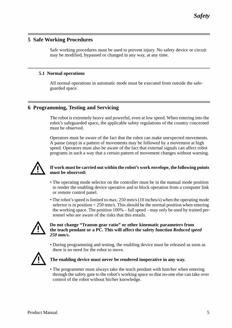
Safety
erned
ents. gh robot rning.
sition r link
mode ring
d per-
n as
ing e over
5 Safe Working Procedures
Safe working procedures must be used to prevent injury. No safety device or circuit may be modified, bypassed or changed in any way, at any time.
5.1 Normal operations
All normal operations in automatic mode must be executed from outside the safe-guarded space.
6 Programming, Testing and Servicing
The robot is extremely heavy and powerful, even at low speed. When entering into the robot’s safeguarded space, the applicable safety regulations of the country concmust be observed.
Operators must be aware of the fact that the robot can make unexpected movemA pause (stop) in a pattern of movements may be followed by a movement at hispeed. Operators must also be aware of the fact that external signals can affectprograms in such a way that a certain pattern of movement changes without wa
If work must be carried out within the robot’s work envelope, the following points must be observed:
• The operating mode selector on the controller must be in the manual mode poto render the enabling device operative and to block operation from a computeor remote control panel.
• The robot’s speed is limited to max. 250 mm/s (10 inches/s) when the operating selector is in position < 250 mm/s. This should be the normal position when entethe working space. The position 100% – full speed – may only be used by trainesonnel who are aware of the risks that this entails.
Do not change “Transm gear ratio” or other kinematic parameters from the teach pendant or a PC. This will affect the safety function Reduced speed 250 mm/s.
• During programming and testing, the enabling device must be released as soothere is no need for the robot to move.
The enabling device must never be rendered inoperative in any way.
• The programmer must always take the teach pendant with him/her when enterthrough the safety gate to the robot’s working space so that no-one else can takcontrol of the robot without his/her knowledge.
Product Manual 5
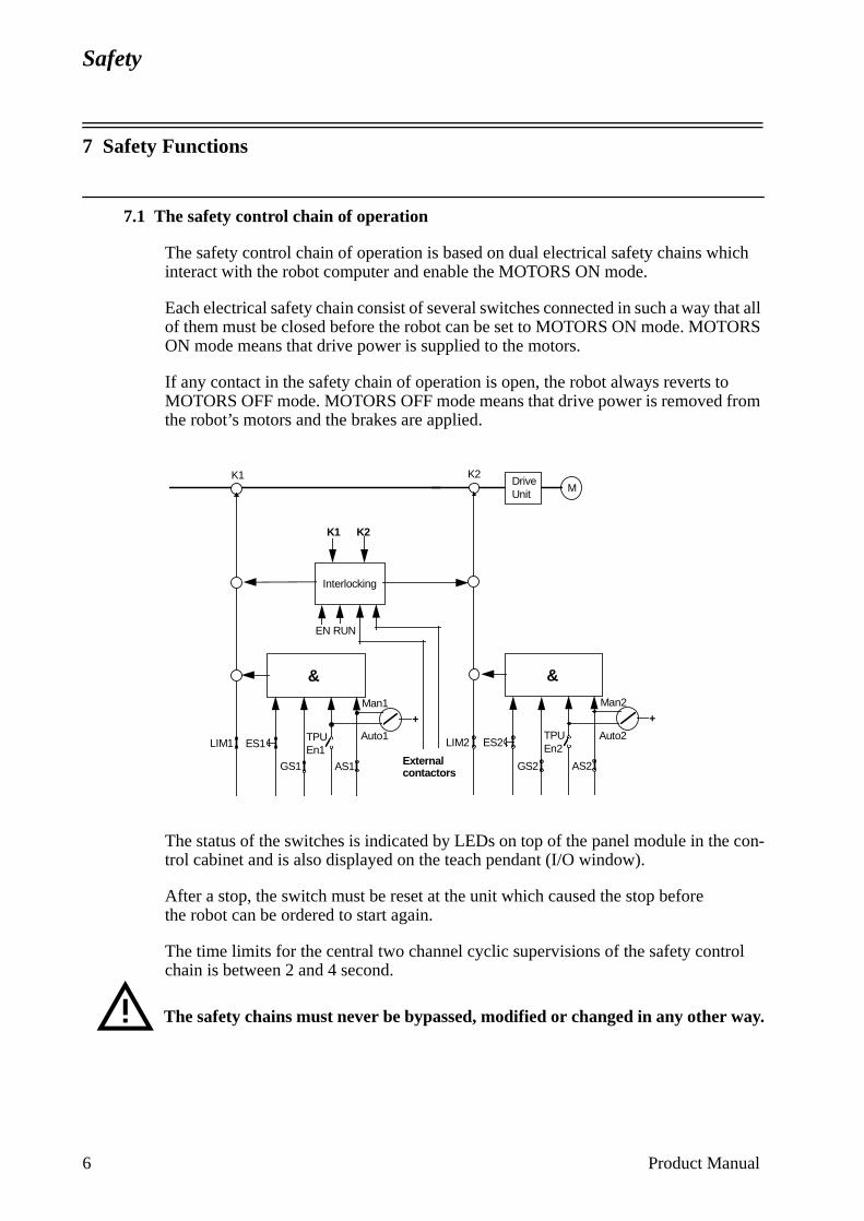
Safety
con-
7 Safety Functions
7.1 The safety control chain of operation
The safety control chain of operation is based on dual electrical safety chains which interact with the robot computer and enable the MOTORS ON mode.
Each electrical safety chain consist of several switches connected in such a way that all of them must be closed before the robot can be set to MOTORS ON mode. MOTORS ON mode means that drive power is supplied to the motors.
If any contact in the safety chain of operation is open, the robot always reverts to MOTORS OFF mode. MOTORS OFF mode means that drive power is removed from the robot’s motors and the brakes are applied.
The status of the switches is indicated by LEDs on top of the panel module in thetrol cabinet and is also displayed on the teach pendant (I/O window).
After a stop, the switch must be reset at the unit which caused the stop before the robot can be ordered to start again.
The time limits for the central two channel cyclic supervisions of the safety control chain is between 2 and 4 second.
The safety chains must never be bypassed, modified or changed in any other way.
&
&
Interlocking
EN RUN
DriveUnit M
K1 K2
LIM1 LIM2 ES2ES1
GS1 GS2 AS2AS1
TPUEn1
TPUEn2
Man2Man1
Auto1 Auto2
K1 K2
+ +
External contactors
6 Product Manual
Safety
con-
chain e
ment
th trol
ers the t and, if
ety ts, etc., emer-m out-
acti-
ode.
e
Product Manual 7
7.2 Emergency stops
An emergency stop should be activated if there is a danger to people or equipment. Built-in emergency stop buttons are located on the operator’s panel of the robottroller and on the teach pendant.
External emergency stop devices (buttons, etc.) can be connected to the safety by the user (see Product Manual/Installation). They must be connected in accordancwith the applicable standards for emergency stop circuits.
Before commissioning the robot, all emergency stop buttons or other safety equipmust be checked by the user to ensure their proper operation.
Before switching to MOTORS ON mode again, establish the reason for the stop and rectify the fault.
7.3 Mode selection using the operating mode selector
The applicable safety requirements for using robots, laid down in accordance wiISO/DIS 10218, are characterised by different modes, selected by means of condevices and with clear-cut positions.
One automatic and two manual modes are available:
The manual mode, < 250 mm/s or 100%, must be selected whenever anyone entrobot’s safeguarded space. The robot must be operated using the teach pendan100% is selected, using Hold-to-run control.
In automatic mode, the operating mode selector is switched to , and all safarrangements, such as doors, gates, light curtains, light beams and sensitive maare active. No-one may enter the robot’s safeguarded space. All controls, such asgency stops, the control panel and control cabinet, must be easily accessible froside the safeguarded space.
Programming and testing at reduced speed
Robot movements at reduced speed can be carried out as follows:
• Set the operating mode selector to <250 mm/s
• Programs can only be started using the teach pendant with the enabling devicevated.
The automatic mode safeguarded space stop (AS) function is not active in this m
Manual mode: < 250 mm/s - max. speed is 250mm/s
100% - full speed
Automatic mode: The robot can be operated via a remote control devic
Safety
acti-
but-
control appli-ed
ling
bling d to the bling
ff, the
e.
AL ive
Testing at full speed
Robot movements at programmed speed can be carried out as follows:
• Set the operating mode selector to 100%
• Programs can only be started using the teach pendant with the enabling devicevated.
For “Hold-to-run control”, the Hold-to-run button must be activated. Releasing theton stops program execution.
The 100% mode may only be used by trained personnel. The applicable laws and regulations of the countries where the robot is used must always be observed.
Automatic operation
Automatic operation may start when the following conditions are fulfilled:
• The operating mode selector is set to
• The MOTORS ON mode is selected
Either the teach pendant can be used to start the program or a connected remotedevice. These functions should be wired and interlocked in accordance with the cable safety instructions and the operator must always be outside the safeguardspace.
7.4 Enabling device
When the operating mode selector is in the MANUAL or MANUAL FULL SPEEDposition, the robot can be set to the MOTORS ON mode by depressing the enabdevice on the teach pendant.
Should the robot revert to the MOTORS OFF mode for any reason while the enadevice is depressed, the latter must be released before the robot can be returneMOTORS ON mode again. This is a safety function designed to prevent the enadevice from being rendered inactive.
When the enabling device is released, the drive power to the motors is switched obrakes are applied and the robot reverts to the MOTORS OFF mode.
If the enabling device is reactivated, the robot changes to the MOTORS ON mod
7.5 Hold-to-run control
This function is always active when the operating mode selector is in the MANUFULL SPEED position. It is possible to set a parameter to make this function actalso when the operating mode selector is in the MANUAL position.
8 Product Manual
Safety
-to-ng the
d
and ating
t, the
ribed
light on of
reset ed in tting
When the Hold-to-run control is active, the enabling device and the Hold-to-run button on the teach pendant must be depressed in order to execute a program. When the button is released, the axis (axes) movements stop and the robot remains in the MOTORS ON mode.
Here is a detailed description of how to execute a program in Hold-to-run control:
• Activate the enabling device on the teach pendant.
• Choose execution mode using the function keys on the teach pendant:
- Start (continuous running of the program)
- FWD (one instruction forwards)
- BWD (one instruction backwards)
• Wait for the Hold-to-run alert box.
• Activate the Hold-to-run button on the teach pendant.
Now the program will run (with the chosen execution mode) as long as the Holdrun button is pressed. Releasing the button stops program execution and activatibutton will start program execution again.
For FWD and BWD execution modes, the next instruction is run by releasing anactivating the Hold-to-run button.
It is possible to change execution mode when the Hold-to-run button is releasedthen continue the program execution with the new execution mode, by just activthe Hold-to-run button again, i.e. no alert box is shown.
If the program execution was stopped with the Stop button on the teach pendanprogram execution will be continued by releasing and activating the Hold-to-runbutton.
When the enabling device on the teach pendant is released, the sequence descabove must be repeated from the beginning.
7.6 General Mode Safeguarded Stop (GS) connection
The GS connection is provided for interlocking external safety devices, such as curtains, light beams or sensitive mats. The GS is active regardless of the positithe operating mode selector.
When this connection is open the robot changes to the MOTORS OFF mode. Toto MOTORS ON mode, the device that initiated the safety stop must be interlockaccordance with applicable safety regulations. This is not normally done by resethe device itself.
Product Manual 9
Safety
in e to
or by s or d. If r soft-
used
S
ust
10 Product Manual
7.7 Automatic Mode Safeguarded Stop (AS) connection
The AS connection is provided for interlocking external safety devices, such as light curtains, light beams or sensitive mats used externally by the system builder. The AS is especially intended for use in automatic mode, during normal program execution.
The AS is by-passed when the operating mode selector is in the MANUAL or MANUAL FULL SPEED position.
7.8 Limiting the working space
For certain applications, movement about the robot’s main axes must be limited order to create a sufficiently large safety zone. This will reduce the risk of damagthe robot if it collides with external safety arrangements, such as barriers, etc.
Movement about axes 1, 2 and 3 can be limited with adjustable mechanical stopsmeans of electrical limit switches. If the working space is limited by means of stopswitches, the corresponding software limitation parameters must also be changenecessary, movement of the three wrist axes can also be limited by the computeware. Limitation of movement of the axes must be carried out by the user.
7.9 Supplementary functions
Functions via specific digital inputs:
• A stop can be activated via a connection with a digital input. Digital inputs can beto stop programs if, for example, a fault occurs in the peripheral equipment.
Functions via specific digital outputs:
• Error – indicates a fault in the robot system.
• Cycle_on – indicates that the robot is executing a program.
• MotOnState/MotOffState – indicates that the robot is in MOTORS ON / MOTOROFF mode.
• EmStop - indicates that the robot is in emergency stop state.
• AutoOn - indicates that the robot is in automatic mode.
8 Safety Risks Related to End Effectors
8.1 Gripper
If a gripper is used to hold a workpiece, inadvertent loosening of the workpiece mbe prevented.
Safety
afety ction.
urned
8.2 Tools/workpieces
It must be possible to turn off tools, such as milling cutters, etc., safely. Make sure that guards remain closed until the cutters stop rotating.
Grippers must be designed so that they retain workpieces in the event of a power fail-ure or a disturbance of the controller. It should be possible to release parts by manual operation (valves).
8.3 Pneumatic/hydraulic systems
Special safety regulations apply to pneumatic and hydraulic systems.
Residual energy may be present in these systems so, after shutdown, particular care must be taken.
The pressure in pneumatic and hydraulic systems must be released before starting to repair them. Gravity may cause any parts or objects held by these systems to drop. Dump valves should be used in case of emergency. Shot bolts should be used to prevent tools, etc., from falling due to gravity.
9 Risks during Operation Disturbances
If the working process is interrupted, extra care must be taken due to risks other than those associated with regular operation. Such an interruption may have to be rectified manually.
Remedial action must only ever be carried out by trained personnel who are familiar with the entire installation as well as the special risks associated with its different parts.
The industrial robot is a flexible tool which can be used in many different industrial applications. All work must be carried out professionally and in accordance with appli-cable safety regulations. Care must be taken at all times.
10 Risks during Installation and Service
To prevent injuries and damage during the installation of the robot system, the regula-tions applicable in the country concerned and the instructions of ABB Robotics must be complied with. Special attention must be paid to the following points:
• The supplier of the complete system must ensure that all circuits used in the sfunction are interlocked in accordance with the applicable standards for that fun
• The instructions in the Product Manual/Installation must always be followed.
• The mains supply to the robot must be connected in such a way that it can be toff outside the robot’s working space.
Product Manual 11
Safety
er-plica-
the
ront of
work-
ble for
em in
er FF)
ing
dition y the
ay be
er.
ing
• The supplier of the complete system must ensure that all circuits used in the emgency stop function are interlocked in a safe manner, in accordance with the apble standards for the emergency stop function.
• Emergency stop buttons must be positioned in easily accessible places so thatrobot can be stopped quickly.
• Safety zones, which have to be crossed before admittance, must be set up in fthe robot’s working space. Light beams or sensitive mats are suitable devices.
• Turntables or the like should be used to keep the operator away from the robot’sing space.
• Those in charge of operations must make sure that safety instructions are availathe installation in question.
• Those who install the robot must have the appropriate training for the robot systquestion and in any safety matters associated with it.
Although troubleshooting may, on occasion, have to be carried out while the powsupply is turned on, the robot must be turned off (by setting the mains switch to Owhen repairing faults, disconnecting electric leads and disconnecting or connectunits.
Even if the power supply for the robot is turned off, you can still injure yourself.
• The axes are affected by the force of gravity when the brakes are released. In adto the risk of being hit by moving robot parts, you run the risk of being crushed btie rod.
• Energy, stored in the robot for the purpose of counterbalancing certain axes, mreleased if the robot, or parts thereof, is dismantled.
• When dismantling/assembling mechanical units, watch out for falling objects.
• Be aware of stored energy (DC link) and hot parts in the controller.
• Units inside the controller, e.g. I/O modules, can be supplied with external pow
11 Risks Associated with Live Electric Parts
Controller
A danger of high voltage is associated with the following parts:
- The mains supply/mains switch
- The power unit
- The power supply unit for the computer system (55 V AC)
- The rectifier unit (260 V AC and 370 V DC. NB: Capacitors!)
- The drive unit (370 V DC)
- The service outlets (115/230 VAC)
- The power supply unit for tools, or special power supply units for the machinprocess
12 Product Manual
Safety
- The external voltage connected to the control cabinet remains live even when the robot is disconnected from the mains.
- Additional connections
Manipulator
A danger of high voltage is associated with the manipulator in:
- The power supply for the motors (up to 370 V DC)
- The user connections for tools or other parts of the installation (see Installation, max. 230 V AC)
Tools, material handling devices, etc.
Tools, material handling devices, etc., may be live even if the robot system is in the OFF position. Power supply cables which are in motion during the working process may be damaged.
12 Emergency Release of Mechanical Arm
If an emergency situation occur where a person is caught by the mechanical robot arm, the brake release buttons should be pressed whereby the arms can be moved to release the person. To move the arms by manpower is normally possible on the smaller robots (1400 and 2400), but for the bigger ones it might not be possible without a mechanical lifting device, like an overhead crane.
If power is not available the brakes are applied, and therefore manpower might not be sufficient for any robot.
Before releasing the brakes, secure that the weight of the arms not enhance the press force on the caught person.
13 Limitation of Liability
The above information regarding safety must not be construed as a warranty by ABB Robotics that the industrial robot will not cause injury or damage even if all safety instructions have been complied with.
14 Related Information
Described in:
Installation of safety devices Product Manual - Installation and Commissioning
Changing robot modes User’s Guide - Starting up
Limiting the working space Product Manual - Installation and Commissioning
Product Manual 13

Safety
14 Product Manual
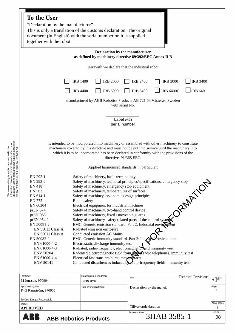
We
rese
rve
all r
ight
s in
this
doc
umen
t and
in th
ein
form
atio
n co
ntai
ned
ther
ein.
Rep
rodu
ctio
n, u
se o
rdi
sclo
sure
to th
ird p
artie
s w
ithou
t exp
ress
aut
horit
y is
stric
tly fo
rbid
den.
A
BB
Rob
otic
s P
rodu
cts
AB
No.of pages
Rev. ind.
TitlePrepared
Approved by,date
Responsible department
Take over department
Document No
ABB Robotics Products
K-G Ramström, 970905Declaration by the manuf.
Tillverkardeklaration
M Jonsson, 970904Technical Provisions
SEROP/K
3HAB 3585-1APPROVED 1
08
Product Design Responsible
Page
1
Status
Declaration by the manufactureras defined by machinery directive 89/392/EEC Annex II B
Herewith we declare that the industrial robot
IRB 1400 IRB 2000 IRB 2400 IRB 3000 IRB 3400
IRB 4400 IRB 6000 IRB 6400 IRB 6400C IRB 640
manufactured by ABB Robotics Products AB 721 68 Västerås, Swedenwith serial No.
Label withserial number
is intended to be incorporated into machinery or assembled with other machinery to constitutemachinery covered by this directive and must not be put into service until the machinery into
which it is to be incorporated has been declared in conformity with the provisions of thedirective, 91/368 EEC.
Applied harmonised standards in particular:
EN 292-1 Safety of machinery, basic terminologyEN 292-2 Safety of machinery, technical principles/specifications, emergency stopEN 418 Safety of machinery, emergency stop equipmentEN 563 Safety of machinery, temperatures of surfacesEN 614-1 Safety of machiney, ergonomic design principlesEN 775 Robot safetyEN 60204 Electrical equipment for industrial machinesprEN 574 Safety of machinery, two-hand control deviceprEN 953 Safety of machinery, fixed / moveable guardsprEN 954-1 Safety of machinery, safety related parts of the control systemEN 50081-2 EMC, Generic emission standard. Part 2: Industrial environment
EN 55011 Class A Radiated emission enclosureEN 55011 Class A Conducted emission AC Mains
EN 50082-2 EMC, Generic immunity standard. Part 2: Industrial environmentEN 61000-4-2 Electrostatic discharge immunity testEN 61000-4-3 Radiated, radio-frequency, electromagnetic field immunity yestENV 50204 Radeated electromagnetic field from digital radio telephones, immunity testEN 61000-4-4 Electrical fast transient/burst immunity testENV 50141 Conducted disturbences induced by radio-frequency fields, immunity test
To the User“Declaration by the manufacturer”.This is only a translation of the customs declaration. The original document (in English) with the serial number on it is supplied together with the robot
ONLY F
OR INFORM
ATION
ABB ROBOTICS PRODUCTS AB CONFIGURATION LIST
Robot type: Revision: Manufact order no: Serial no:
For RAC: RAC Ref no: Sales order no:
Tested and approved: Date Name
MANIPULATOR:
CONTROL SYSTEM:
ROBOT SYSTEM:
DateDelivery from factory:
Delivery to customer:
Acceptance by customer:
Customer information:
Customer:
Address:
OPTIONS/DOCUMENTATION
QTY OPTION/PARTNO REVISION DESCRIPTION
To the User
The Configuration List is an individual specification of the robot system delivered regarding configuration and extent.
On delivery, the complete document is placed in the robot controller.
System Description
CONTENTSPage
1 Structure .......................................................................................................................... 3
1.1 Manipulator ............................................................................................................ 3
1.2 Controller................................................................................................................ 7
1.3 Electronics unit ....................................................................................................... 8
2 Computer System............................................................................................................ 11
3 Servo System.................................................................................................................... 13
3.1 Principle function ................................................................................................... 13
3.2 Regulation............................................................................................................... 13
3.3 Controlling the robot .............................................................................................. 13
3.4 Overload protection ................................................................................................ 14
4 I/O System........................................................................................................................ 15
5 Safety System................................................................................................................... 17
5.1 The chain of operation............................................................................................ 17
5.2 MOTORS ON and MOTORS OFF modes............................................................. 18
5.3 Safety stop signals .................................................................................................. 18
5.4 Limitation of velocity ............................................................................................. 19
5.5 ENABLE ................................................................................................................ 19
5.6 24 V supervision..................................................................................................... 19
5.7 Monitoring .............................................................................................................. 19
6 External Axes................................................................................................................... 21
Product Manual 1

System Description
CONTENTSPage
2 Product Manual
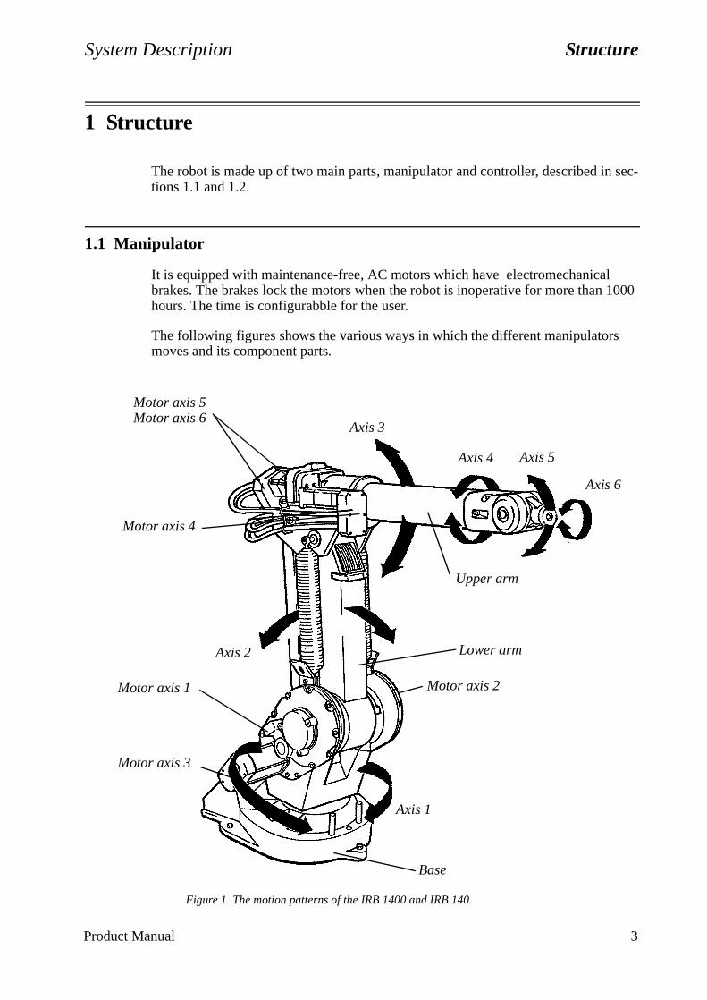
System Description Structure
1 Structure
The robot is made up of two main parts, manipulator and controller, described in sec-tions 1.1 and 1.2.
1.1 Manipulator
It is equipped with maintenance-free, AC motors which have electromechanical brakes. The brakes lock the motors when the robot is inoperative for more than 1000 hours. The time is configurabble for the user.
The following figures shows the various ways in which the different manipulators moves and its component parts.
Figure 1 The motion patterns of the IRB 1400 and IRB 140.
Motor axis 5Motor axis 6
Motor axis 4
Axis 2
Axis 1
Motor axis 1
Axis 3
Motor axis 2
Motor axis 3
Axis 4 Axis 5
Axis 6
Upper arm
Lower arm
Base
Product Manual 3
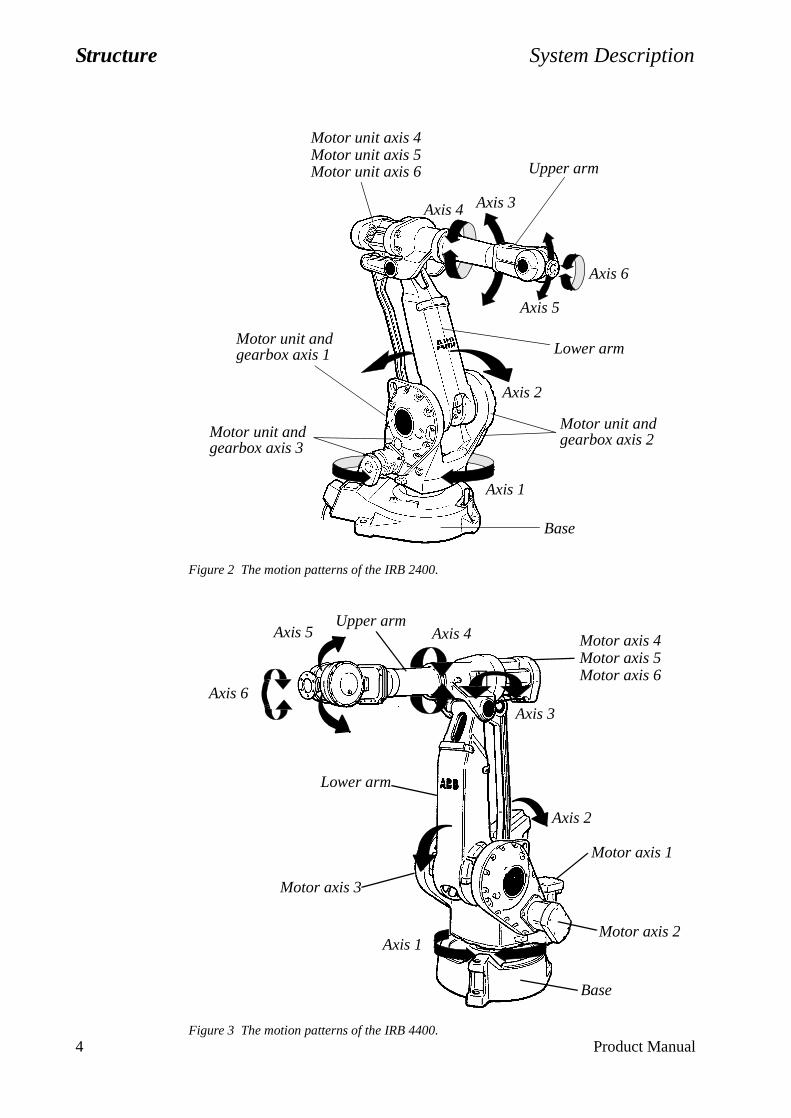
Structure System Description
4 Product Manual
Figure 2 The motion patterns of the IRB 2400.
Figure 3 The motion patterns of the IRB 4400.
Motor unit axis 4Motor unit axis 5
Upper arm
Motor unit andgearbox axis 2
Base
Motor unit andgearbox axis 3
Lower arm
Axis 1
Axis 2
Axis 3Axis 4
Axis 5
Axis 6
Motor unit axis 6
Motor unit andgearbox axis 1
Motor axis 4Motor axis 5Motor axis 6
Axis 2
Axis 1
Motor axis 1
Axis 3
Motor axis 2
Motor axis 3
Axis 4Axis 5
Axis 6
Upper arm
Lower arm
Base

System Description Structure
Figure 4 The motion patterns of the IRB 6400.
Figure 5 The motion patterns of the IRB 640.
Motor axis 4 Motor axis 5 Upper arm
Motor axis 2
Base
Motor axis 3Lower arm
Axis 1
Axis 2
Axis 3
Axis 4
Axis 5
Axis 6
Motor axis 6
Motor axis 1
Axis 1
Axis 2
Axis 3
Axis 6
Upper arm
Lower arm
Motor axis 2
Motor axis 6
Motor axis 1
Motor axis 3
Product Manual 5
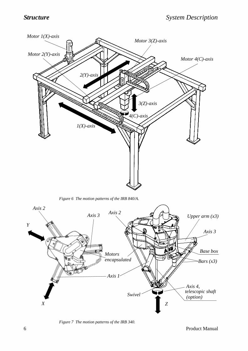
Structure System Description
Figure 6 The motion patterns of the IRB 840/A.
Figure 7 The motion patterns of the IRB 340.
4(C)-axis
1(X)-axis
2(Y)-axis
3(Z)-axis
Motor 1(X)-axis
Motor 4(C)-axis
Motor 3(Z)-axis
Motor 2(Y)-axis
Axis 2
Axis 1
Axis 3
Axis 4,
Bars (x3)
Upper arm (x3)
telescopic shaftSwivel
Axis 2
Axis 3
X
Y
Z
Base box
(option)
Motorsencapsulated
6 Product Manual
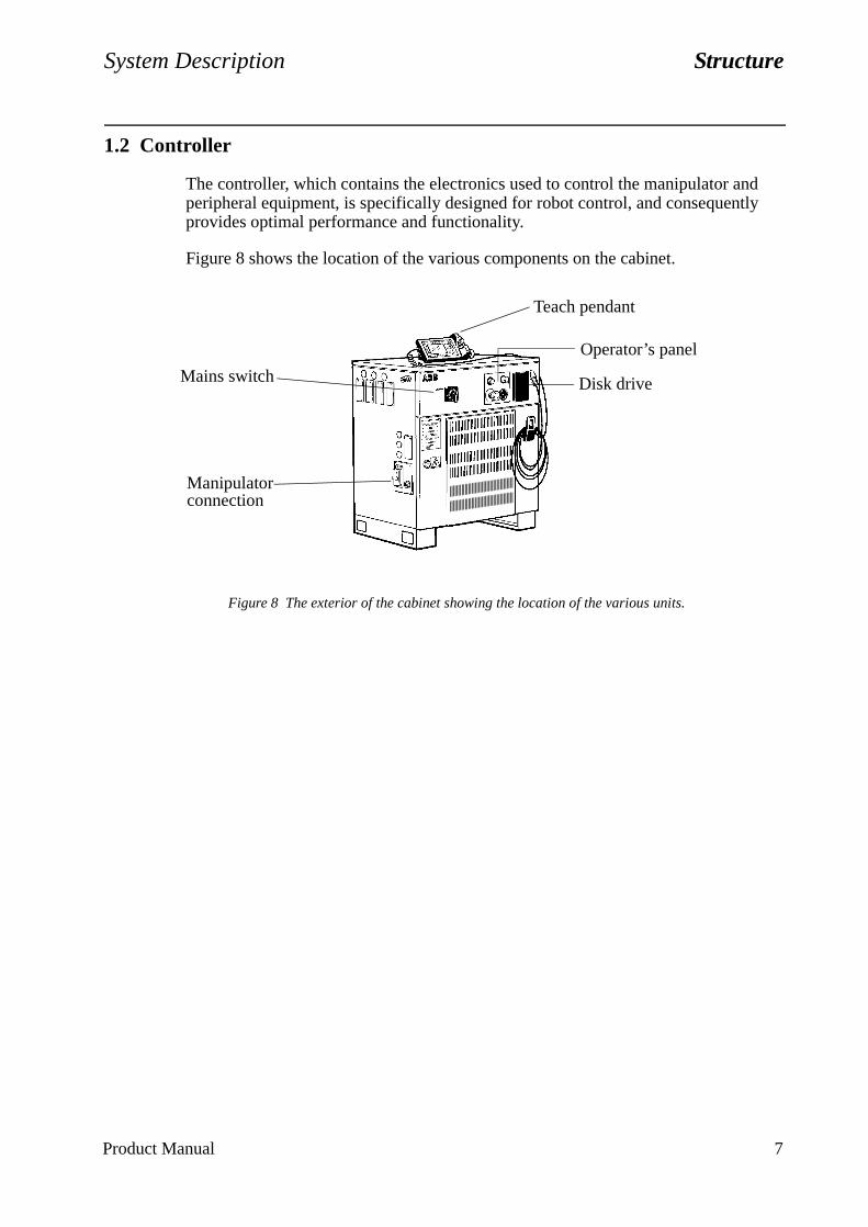
System Description Structure
1.2 Controller
The controller, which contains the electronics used to control the manipulator and peripheral equipment, is specifically designed for robot control, and consequently provides optimal performance and functionality.
Figure 8 shows the location of the various components on the cabinet.
Figure 8 The exterior of the cabinet showing the location of the various units.
Teach pendant
Operator’s panel
Disk driveMains switch
Manipulator connection
Product Manual 7
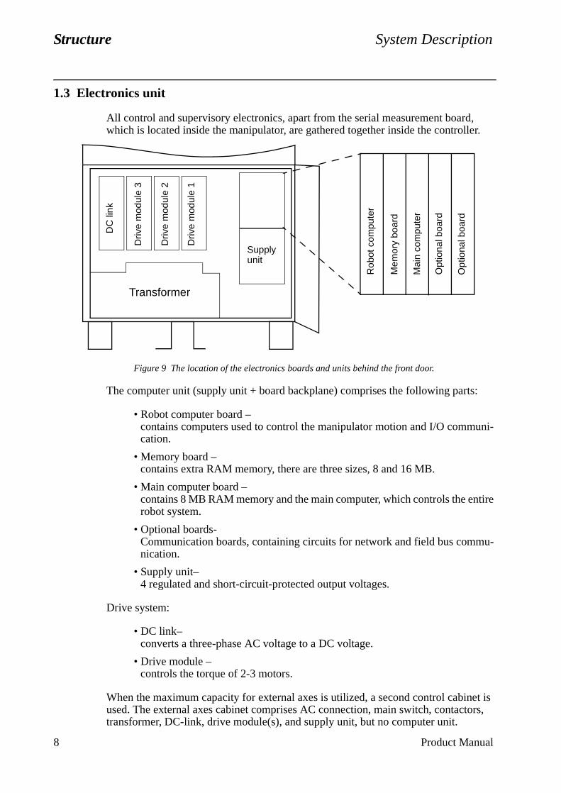
Structure System Description
uni-
tire
u-
et is ors,
1.3 Electronics unit
All control and supervisory electronics, apart from the serial measurement board, which is located inside the manipulator, are gathered together inside the controller.
Figure 9 The location of the electronics boards and units behind the front door.
The computer unit (supply unit + board backplane) comprises the following parts:
• Robot computer board –contains computers used to control the manipulator motion and I/O commcation.
• Memory board –contains extra RAM memory, there are three sizes, 8 and 16 MB.
• Main computer board –contains 8 MB RAM memory and the main computer, which controls the enrobot system.
• Optional boards-Communication boards, containing circuits for network and field bus commnication.
• Supply unit–4 regulated and short-circuit-protected output voltages.
Drive system:
• DC link–converts a three-phase AC voltage to a DC voltage.
• Drive module –controls the torque of 2-3 motors.
When the maximum capacity for external axes is utilized, a second control cabinused. The external axes cabinet comprises AC connection, main switch, contacttransformer, DC-link, drive module(s), and supply unit, but no computer unit.
Transformer
DC
link
Driv
e m
odul
e 3
Driv
e m
odul
e 2
Driv
e m
odul
e 1
Supply unit
Rob
ot c
ompu
ter
Mai
n co
mpu
ter
Opt
iona
l boa
rd
Opt
iona
l boa
rd
Mem
ory
boar
d
8 Product Manual

System Description Structure
afety.
and
with nits
. The ation
Figure 10 The location of units under the top cover.
• Lithium batteries for memory back-up.
• Panel unit –gathers and coordinates all signals that affect operational and personal s
• I/O units –enables communication with external equipment by means of digital inputsoutputs, analog signals or field buses.
I/O units can alternatively be located outside the cabinet. Communication robot data is implemented via a stranded wire CAN bus, which allows the uto be positioned close to the process.
• Serial measurement board (in the manipulator) –gathers resolver data and transfers it serially to the robot computer boardserial measurement board is battery-backed so that the revolution informcannot be lost during a power failure.
I/O units (x4)
AC connection
Motors On and brake contactors Floppy disk
Panel unit
Lithium batteries
Product Manual 9

Structure System Description
10 Product Manual
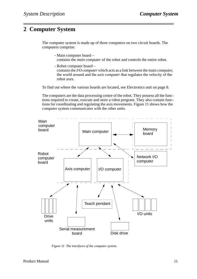
System Description Computer System
er,
e 8.
e func- func-
w the
2 Computer System
The computer system is made up of three computers on two circuit boards. The computers comprise:
- Main computer board –contains the main computer of the robot and controls the entire robot.
- Robot computer board –contains the I/O computer which acts as a link between the main computthe world around and the axis computer that regulates the velocity of therobot axes.
To find out where the various boards are located, see Electronics unit on pag
The computers are the data processing centre of the robot. They possess all thtions required to create, execute and store a robot program. They also containtions for coordinating and regulating the axis movements. Figure 11 shows hocomputer system communicates with the other units.
Figure 11 The interfaces of the computer system.
Main computer
I/O computerAxis computer
I/O units
Disk drive
Teach pendant
Drive units
Serial measurementboard
Main computer board
Robot computer board
Memory board
Network I/Ocomputer
Product Manual 11

Computer System System Description
12 Product Manual
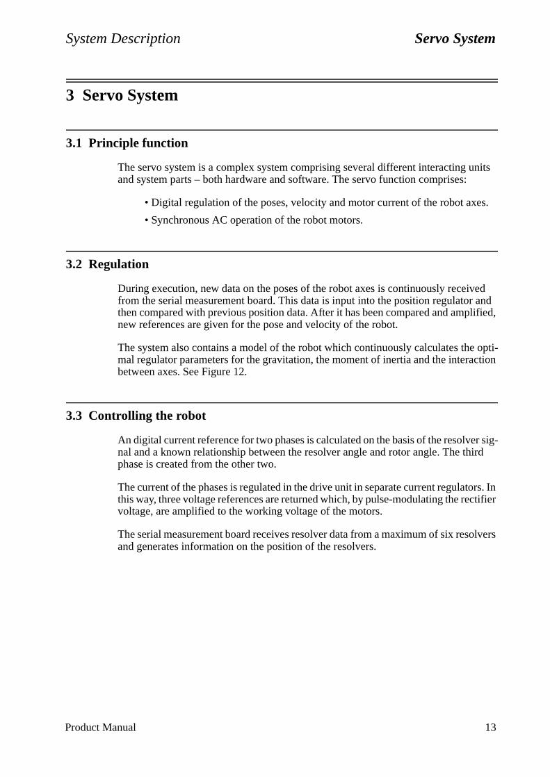
System Description Servo System
s.
ved and lified,
opti-ction
er sig-ird
ors. In ctifier
olvers
3 Servo System
3.1 Principle function
The servo system is a complex system comprising several different interacting units and system parts – both hardware and software. The servo function comprises:
• Digital regulation of the poses, velocity and motor current of the robot axe
• Synchronous AC operation of the robot motors.
3.2 Regulation
During execution, new data on the poses of the robot axes is continuously receifrom the serial measurement board. This data is input into the position regulatorthen compared with previous position data. After it has been compared and ampnew references are given for the pose and velocity of the robot.
The system also contains a model of the robot which continuously calculates themal regulator parameters for the gravitation, the moment of inertia and the interabetween axes. See Figure 12.
3.3 Controlling the robot
An digital current reference for two phases is calculated on the basis of the resolvnal and a known relationship between the resolver angle and rotor angle. The thphase is created from the other two.
The current of the phases is regulated in the drive unit in separate current regulatthis way, three voltage references are returned which, by pulse-modulating the revoltage, are amplified to the working voltage of the motors.
The serial measurement board receives resolver data from a maximum of six resand generates information on the position of the resolvers.
Product Manual 13
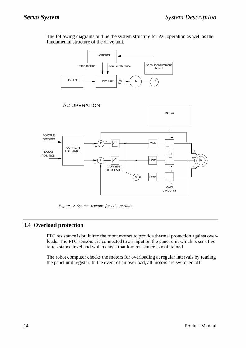
Servo System System Description
The following diagrams outline the system structure for AC operation as well as the fundamental structure of the drive unit.
Figure 12 System structure for AC operation.
3.4 Overload protection
PTC resistance is built into the robot motors to provide thermal protection against over-loads. The PTC sensors are connected to an input on the panel unit which is sensitive to resistance level and which check that low resistance is maintained.
The robot computer checks the motors for overloading at regular intervals by reading the panel unit register. In the event of an overload, all motors are switched off.
-
-+
+
+
-
-
V
W
Computer
DC link Drive Unit M R
Serial measurement board
Torque reference
AC OPERATION
U
PWM
PWM
PWMM
MM
+
CURRENTREGULATOR
M+
-MAIN
CIRCUITS
DC link
Rotor position
CURRENTESTIMATOR
TORQUEreference
ROTORPOSITION
14 Product Manual
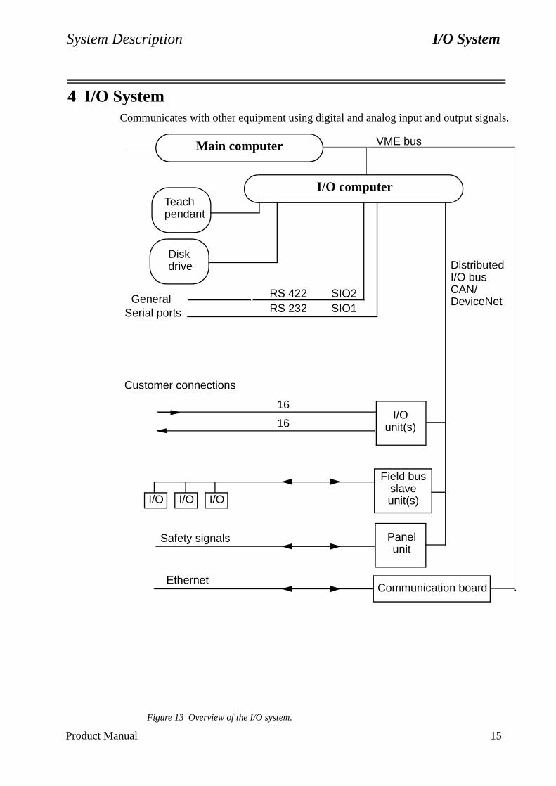
System Description I/O System
4 I/O SystemCommunicates with other equipment using digital and analog input and output signals.
Figure 13 Overview of the I/O system.
I/Ounit(s)
Panelunit
Field busslaveunit(s)
RS 422 SIO2RS 232 SIO1
GeneralSerial ports
I/O I/O I/O
Customer connections
16
16
Safety signals
I/O computerTeachpendant
Diskdrive Distributed
I/O busCAN/DeviceNet
Main computer VME bus
Communication boardEthernet
Product Manual 15

I/O System System Description
16 Product Manual
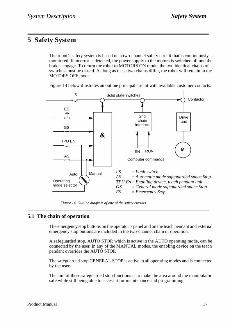
System Description Safety System
sly d the of
n the
cts.
xternal
n be each
ected
ulator
5 Safety System
The robot’s safety system is based on a two-channel safety circuit that is continuoumonitored. If an error is detected, the power supply to the motors is switched off anbrakes engage. To return the robot to MOTORS ON mode, the two identical chainsswitches must be closed. As long as these two chains differ, the robot will remain iMOTORS OFF mode.
Figure 14 below illustrates an outline principal circuit with available customer conta
Figure 14 Outline diagram of one of the safety circuits.
5.1 The chain of operation
The emergency stop buttons on the operator’s panel and on the teach pendant and eemergency stop buttons are included in the two-channel chain of operation.
A safeguarded stop, AUTO STOP, which is active in the AUTO operating mode, caconnected by the user. In any of the MANUAL modes, the enabling device on the tpendant overrides the AUTO STOP.
The safeguarded stop GENERAL STOP is active in all operating modes and is connby the user.
The aim of these safeguarded stop functions is to make the area around the manipsafe while still being able to access it for maintenance and programming.
Manual LS = Limit switchAS = Automatic mode safeguarded space StopTPU En= Enabling device, teach pendant unitGS = General mode safeguarded space StopES = Emergency Stop
2ndchain
interlock
AS
GS
Auto
M
Driveunit
ContactorSolid state switchesLS
TPU En
ES
EN RUN
Computer commands
&
Operating mode selector
Product Manual 17
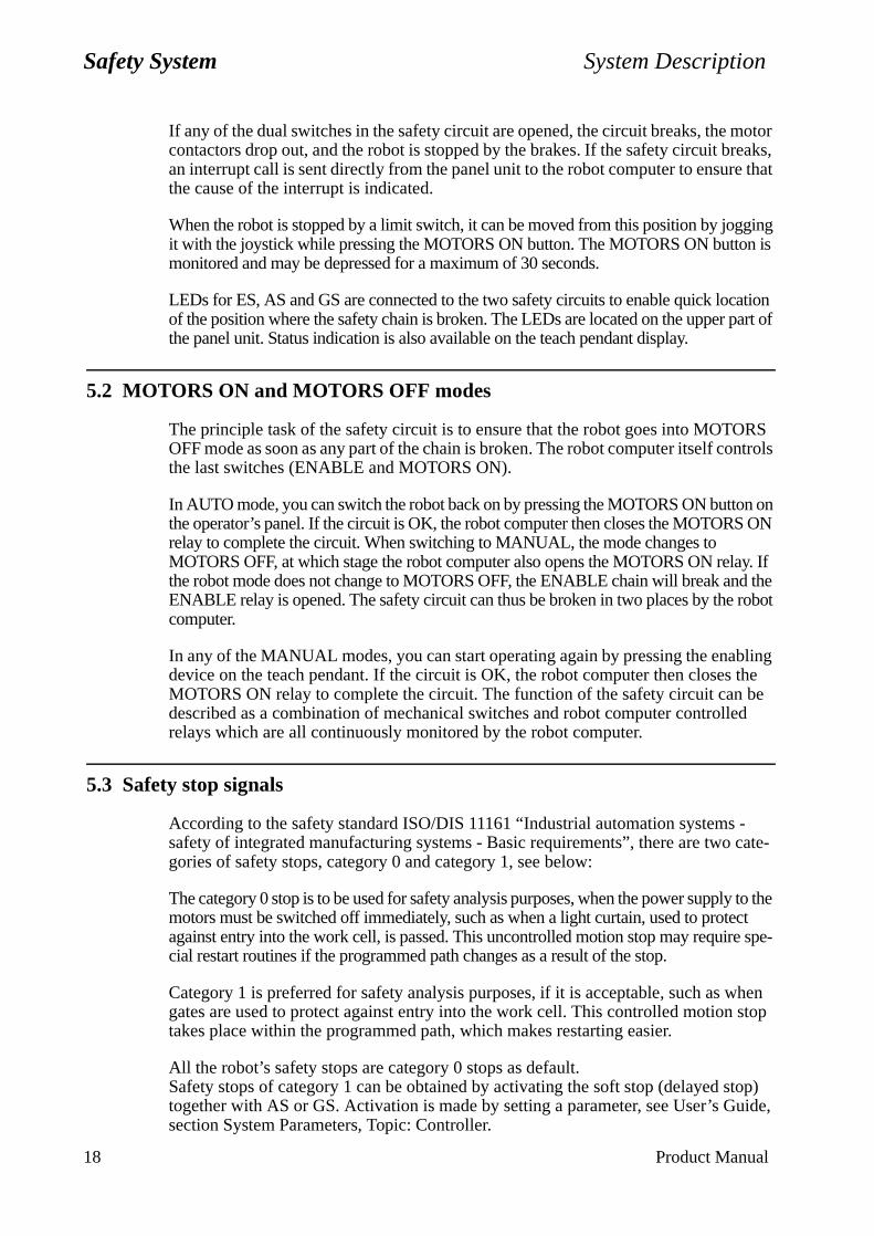
Safety System System Description
ON
ay. If d the robot
bling the be d
- cate-
ly to the ct spe-
hen stop
top) uide,
18 Product Manual
If any of the dual switches in the safety circuit are opened, the circuit breaks, the motor contactors drop out, and the robot is stopped by the brakes. If the safety circuit breaks, an interrupt call is sent directly from the panel unit to the robot computer to ensure that the cause of the interrupt is indicated.
When the robot is stopped by a limit switch, it can be moved from this position by jogging it with the joystick while pressing the MOTORS ON button. The MOTORS ON button is monitored and may be depressed for a maximum of 30 seconds.
LEDs for ES, AS and GS are connected to the two safety circuits to enable quick location of the position where the safety chain is broken. The LEDs are located on the upper part of the panel unit. Status indication is also available on the teach pendant display.
5.2 MOTORS ON and MOTORS OFF modes
The principle task of the safety circuit is to ensure that the robot goes into MOTORS OFF mode as soon as any part of the chain is broken. The robot computer itself controls the last switches (ENABLE and MOTORS ON).
In AUTO mode, you can switch the robot back on by pressing the MOTORS ON button on the operator’s panel. If the circuit is OK, the robot computer then closes the MOTORSrelay to complete the circuit. When switching to MANUAL, the mode changes to MOTORS OFF, at which stage the robot computer also opens the MOTORS ON relthe robot mode does not change to MOTORS OFF, the ENABLE chain will break anENABLE relay is opened. The safety circuit can thus be broken in two places by thecomputer.
In any of the MANUAL modes, you can start operating again by pressing the enadevice on the teach pendant. If the circuit is OK, the robot computer then closesMOTORS ON relay to complete the circuit. The function of the safety circuit can described as a combination of mechanical switches and robot computer controllerelays which are all continuously monitored by the robot computer.
5.3 Safety stop signals
According to the safety standard ISO/DIS 11161 “Industrial automation systems safety of integrated manufacturing systems - Basic requirements”, there are twogories of safety stops, category 0 and category 1, see below:
The category 0 stop is to be used for safety analysis purposes, when the power suppmotors must be switched off immediately, such as when a light curtain, used to proteagainst entry into the work cell, is passed. This uncontrolled motion stop may requirecial restart routines if the programmed path changes as a result of the stop.
Category 1 is preferred for safety analysis purposes, if it is acceptable, such as wgates are used to protect against entry into the work cell. This controlled motion takes place within the programmed path, which makes restarting easier.
All the robot’s safety stops are category 0 stops as default.Safety stops of category 1 can be obtained by activating the soft stop (delayed stogether with AS or GS. Activation is made by setting a parameter, see User’s Gsection System Parameters, Topic: Controller.
System Description Safety System
the
ill
ternal e and
om- read.
ains ard-use.
5.4 Limitation of velocity
To program the robot, the operating mode switch must be turned to MANUAL REDUCED SPEED position. Then the robot’s maximum velocity is limited to 250 mm/s.
5.5 ENABLE
ENABLE is a 24 V signal, generated in the supply unit. The signal is sent throughrobot computer, to the panel unit.
The errors that affect the Enable signal are:
• In the supply unit; errors in the input voltage.
• In the robot computer; errors in the diagnostics or servo control program.
• In the drive unit; regulating errors and overcurrent.
5.6 24 V supervision
If the 24 V supply to the safety circuits drops out, the MOTORS ON contactors wdrop out, causing the motors to switch off.
5.7 Monitoring
Monitoring is carried out using both hardware and software, and comprises the expart of the safety circuits, including switches and operating contacts. The hardwarsoftware parts operate independently of each other.
The following errors may be detected:
All inputs from the safety circuits are linked to registers, which allows the robot cputer to monitor the status. If an interrupt occurs in the circuit, the status can be
If any of the switch functions are incorrectly adjusted, causing only one of the chof operation to be interrupted, the robot computer will detect this. By means of hware interlocking it is not possible to enter MOTORS ON without correcting the ca
Product Manual 19

Safety System System Description
20 Product Manual
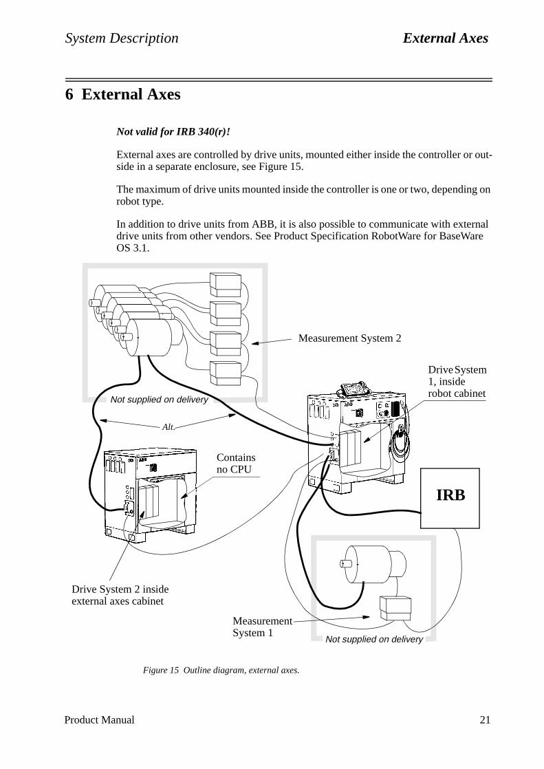
System Description External Axes
6 External Axes
Not valid for IRB 340(r)!
External axes are controlled by drive units, mounted either inside the controller or out-side in a separate enclosure, see Figure 15.
The maximum of drive units mounted inside the controller is one or two, depending on robot type.
In addition to drive units from ABB, it is also possible to communicate with external drive units from other vendors. See Product Specification RobotWare for BaseWare OS 3.1.
Figure 15 Outline diagram, external axes.
IRB
Not supplied on delivery
Alt.
Not supplied on delivery
Measurement System 1
Drive System 2 inside external axes cabinet
Measurement System 2
Drive System 1, inside robot cabinet
Contains no CPU
Product Manual 21

External Axes System Description
22 Product Manual
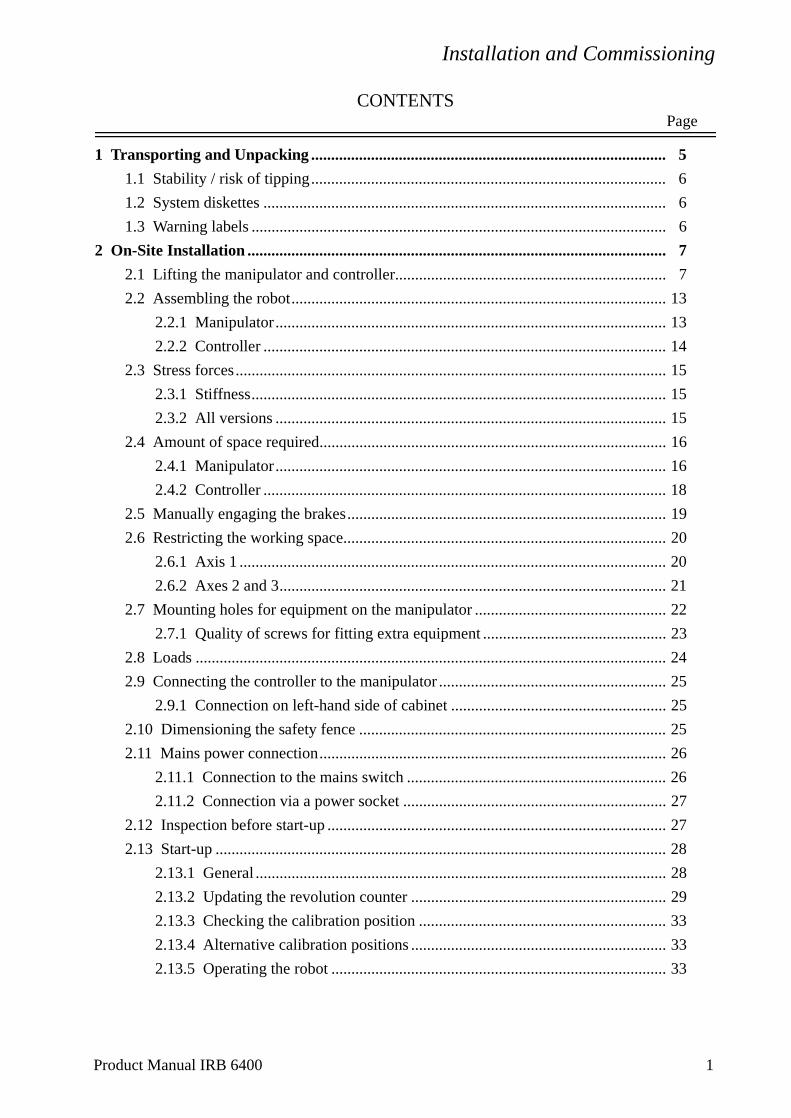
Installation and Commissioning
CONTENTSPage
1 Transporting and Unpacking ......................................................................................... 5
1.1 Stability / risk of tipping......................................................................................... 6
1.2 System diskettes ..................................................................................................... 6
1.3 Warning labels ........................................................................................................ 6
2 On-Site Installation ......................................................................................................... 7
2.1 Lifting the manipulator and controller.................................................................... 7
2.2 Assembling the robot.............................................................................................. 13
2.2.1 Manipulator.................................................................................................. 13
2.2.2 Controller ..................................................................................................... 14
2.3 Stress forces............................................................................................................ 15
2.3.1 Stiffness........................................................................................................ 15
2.3.2 All versions .................................................................................................. 15
2.4 Amount of space required....................................................................................... 16
2.4.1 Manipulator.................................................................................................. 16
2.4.2 Controller ..................................................................................................... 18
2.5 Manually engaging the brakes................................................................................ 19
2.6 Restricting the working space................................................................................. 20
2.6.1 Axis 1 ........................................................................................................... 20
2.6.2 Axes 2 and 3................................................................................................. 21
2.7 Mounting holes for equipment on the manipulator ................................................ 22
2.7.1 Quality of screws for fitting extra equipment .............................................. 23
2.8 Loads ...................................................................................................................... 24
2.9 Connecting the controller to the manipulator ......................................................... 25
2.9.1 Connection on left-hand side of cabinet ...................................................... 25
2.10 Dimensioning the safety fence ............................................................................. 25
2.11 Mains power connection....................................................................................... 26
2.11.1 Connection to the mains switch ................................................................. 26
2.11.2 Connection via a power socket .................................................................. 27
2.12 Inspection before start-up ..................................................................................... 27
2.13 Start-up ................................................................................................................. 28
2.13.1 General ....................................................................................................... 28
2.13.2 Updating the revolution counter ................................................................ 29
2.13.3 Checking the calibration position .............................................................. 33
2.13.4 Alternative calibration positions ................................................................ 33
2.13.5 Operating the robot .................................................................................... 33
Product Manual IRB 6400 1
Installation and Commissioning
CONTENTS
Page3 Connecting Signals.......................................................................................................... 35
3.1 Signal classes.......................................................................................................... 35
3.2 Selecting cables ...................................................................................................... 35
3.3 Interference elimination ......................................................................................... 36
3.4 Connection types .................................................................................................... 36
3.5 Connections ............................................................................................................ 37
3.5.1 To screw terminal......................................................................................... 37
3.5.2 To connectors (option) ................................................................................. 37
3.6 Customer connections on manipulator ................................................................... 39
3.7 Connection to screw terminal................................................................................. 44
3.8 The MOTORS ON / MOTORS OFF circuit .......................................................... 45
3.9 Connection of safety chains ................................................................................... 46
3.9.1 Connection of ES1/ES2 on panel unit ......................................................... 47
3.9.2 Connection to Motor On/Off contactors ...................................................... 48
3.9.3 Connection to operating mode selector ....................................................... 48
3.9.4 Connection to brake contactor ..................................................................... 48
3.10 External customer connections............................................................................. 49
3.11 External safety relay ............................................................................................. 52
3.12 Safeguarded space stop signals ............................................................................ 53
3.12.1 Delayed safeguarded space stop ................................................................ 53
3.13 Available voltage .................................................................................................. 53
3.13.1 24 V I/O supply.......................................................................................... 53
3.13.2 115/230 V AC supply ................................................................................ 54
3.14 External 24 V supply ............................................................................................ 54
3.15 Connection of extra equipment to the manipulator .............................................. 55
3.15.1 Connections on upper arm ......................................................................... 55
3.15.2 Connections on upper arm with CanBus ................................................... 56
3.15.3 Connection of signal lamp on upper arm (option) ..................................... 58
3.16 Distributed I/O units ............................................................................................. 58
3.16.1 General....................................................................................................... 58
3.16.2 Sensors ....................................................................................................... 59
3.16.3 Connection and address keying of the CAN-bus....................................... 59
3.16.4 Digital I/O DSQC 328 (optional)............................................................... 61
3.16.5 AD Combi I/O DSQC 327 (optional) ........................................................ 64
3.16.6 Analog I/O DSQC 355 (optional) .............................................................. 67
3.16.7 Encoder interface unit, DSQC 354 ............................................................ 71
3.16.8 Relay I/O DSQC 332 ................................................................................. 74
3.16.9 Digital 120 VAC I/O DSQC 320 ............................................................... 77
2 Product Manual IRB 6400
Installation and Commissioning
CONTENTSPage
1
93
3
4
95
6
6
97
01
102
2
03
04
08
5
3.17 Field bus units....................................................................................................... 80
3.17.1 RIO (Remote Input Output), remote I/O for Allen-Bradley PLC DSQC 350 .......................................................................................... 80
3.17.2 Interbus-S, slave DSQC 351 ...................................................................... 82
3.17.3 Profibus-DP, slave, DSQC352 ................................................................... 85
3.18 Communication .................................................................................................... 87
3.18.1 Serial links, SIO ......................................................................................... 87
3.18.2 Ethernet communication, DSQC 336......................................................... 89
3.19 External operator’s panel...................................................................................... 9
4 Installing the Control Program...................................................................................... 93
4.1 System diskettes .....................................................................................................
4.1.1 Installation procedure................................................................................... 9
4.2 Calibration of the manipulator................................................................................ 9
4.3 Cold start................................................................................................................. 94
4.4 How to change language, options and IRB types...................................................
4.5 How to use the disk, Manipulator Parameters ................................................ 9
4.6 Robot delivered with software installed.......................................................... 9
4.7 Robot delivered without software installed .................................................... 96
4.8 Saving the parameters on the Controller Parameter disk................................
5 External Axes................................................................................................................... 99
5.1 General.................................................................................................................... 99
5.2 Easy to use kits .......................................................................................................1
5.3 User designed external axes. ..................................................................................
5.3.1 DMC-C.........................................................................................................10
5.3.2 FBU..............................................................................................................1
5.3.3 Measurement System ...................................................................................1
5.3.4 Drive System................................................................................................1
5.3.5 Configuration Files ......................................................................................11
Product Manual IRB 6400 3

Installation and Commissioning
CONTENTSPage
4 Product Manual IRB 6400
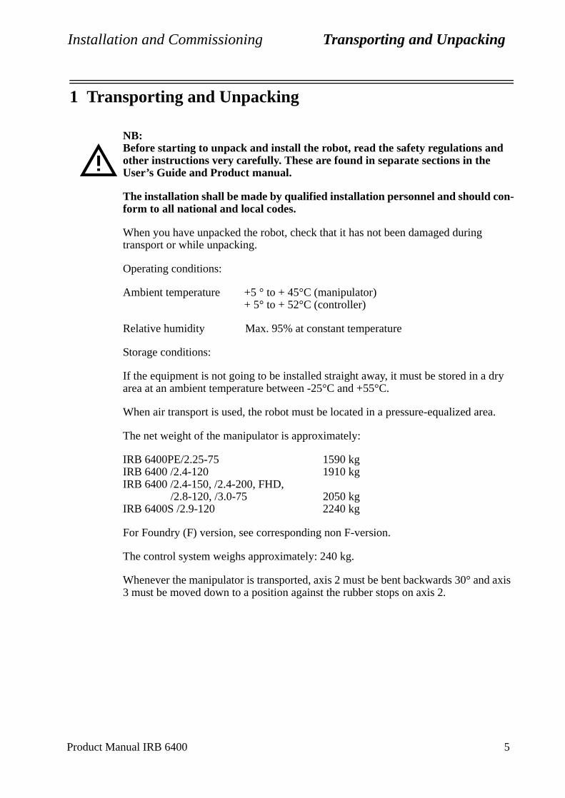
Installation and Commissioning Transporting and Unpacking
dry
ea.
d axis
1 Transporting and Unpacking
NB:Before starting to unpack and install the robot, read the safety regulations and other instructions very carefully. These are found in separate sections in the User’s Guide and Product manual.
The installation shall be made by qualified installation personnel and should con-form to all national and local codes.
When you have unpacked the robot, check that it has not been damaged during transport or while unpacking.
Operating conditions:
Ambient temperature +5 ° to + 45°C (manipulator)+ 5° to + 52°C (controller)
Relative humidity Max. 95% at constant temperature
Storage conditions:
If the equipment is not going to be installed straight away, it must be stored in a area at an ambient temperature between -25°C and +55°C.
When air transport is used, the robot must be located in a pressure-equalized ar
The net weight of the manipulator is approximately:
IRB 6400PE/2.25-75 1590 kgIRB 6400 /2.4-120 1910 kgIRB 6400 /2.4-150, /2.4-200, FHD,
/2.8-120, /3.0-75 2050 kgIRB 6400S /2.9-120 2240 kg
For Foundry (F) version, see corresponding non F-version.
The control system weighs approximately: 240 kg.
Whenever the manipulator is transported, axis 2 must be bent backwards 30° an3 must be moved down to a position against the rubber stops on axis 2.
Product Manual IRB 6400 5

Transporting and Unpacking Installation and Commissioning
1.1 Stability / risk of tipping
When the manipulator is not fastened to the floor and standing still, the manipu-lator is not stable in the whole working area. When the arms are moved, care must be taken so that the centre of gravity is not displaced, as this could cause the manipulator to tip over.
The following table shows the positions where there is a risk of tipping and refers to figures in chapter 3.8 in Product Specification IRB 6400, for definition of position 0 and 5.
no = stableyes = risk of tipping
For Foundry (F) version, see corresponding non F-version.
1.2 System diskettes
The diskettes in the box, fixed to the shelf for the teach pendant, should be copied (in a PC) before they are used. Never work with the original diskettes. When you have made copies, store the originals in a safe place.
Do not store diskettes inside the controller due to the high temperatures there.
1.3 Warning labels
Two warning labels are supplied with the IRB 6400FHD model to show that it is not permissible to use the robot outside the working area of the wrist, when the wrist is loaded as shown in the load diagram in the Product Specification. These labels must be attached on suitable surfaces to attract attention, e.g. on the controller and/or the gate into the robot cell. For further information see Chapter 3.4 in the Product Specification IRB 6400.
If the robot is used outside this working area, its brakes may not be able to control the load. This can cause personal in jury.
Version Working area, position 0load = 0 kg load = max
Working area, position 5load = 0 kg load = max
2.4-1202.4-1502.4-200, FHD2.8-1203.0-75S /2.9-120PE/2.25-75
nononononoyesno
nononononoyesyes
nononoyesyesyesyes
yesyesyesyesyesyesyes
6 Product Manual IRB 6400
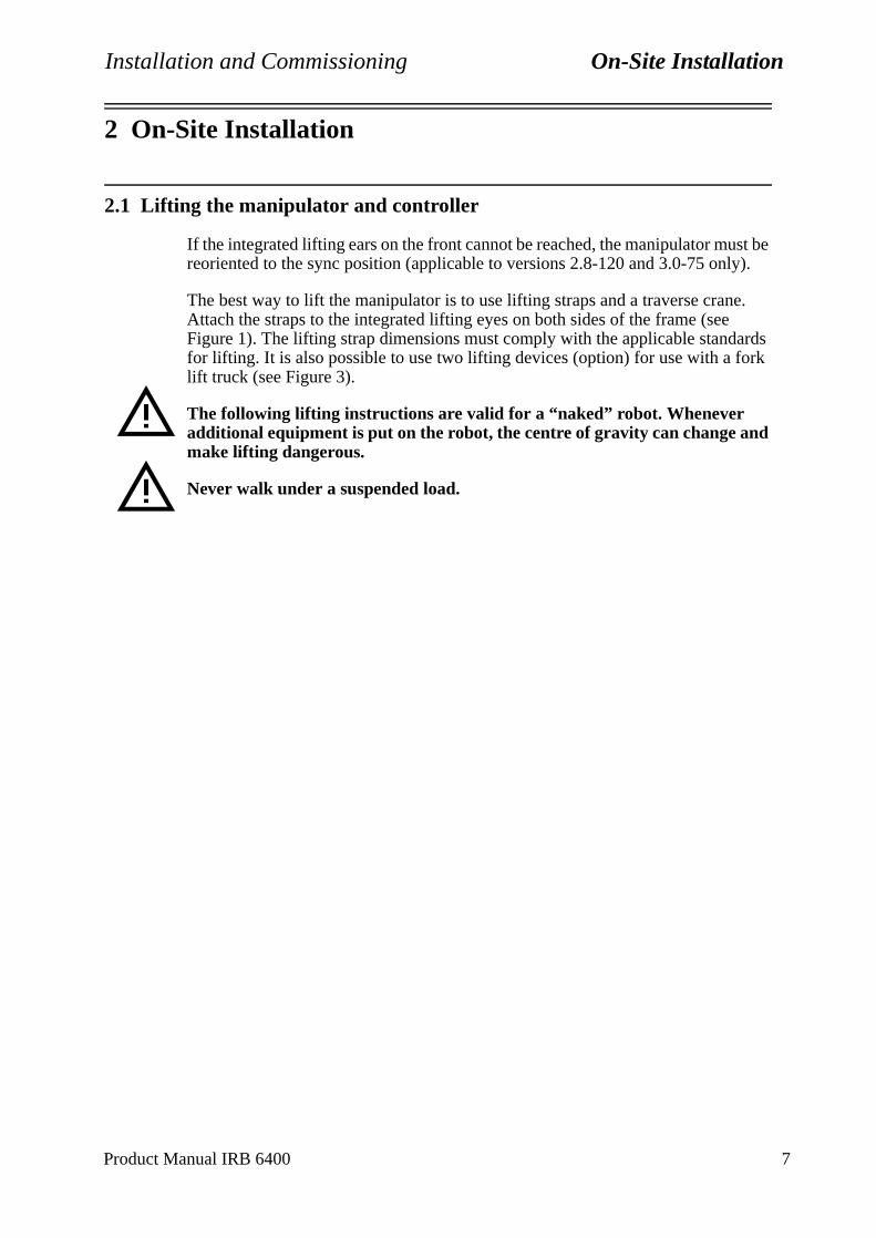
Installation and Commissioning On-Site Installation
2 On-Site Installation
2.1 Lifting the manipulator and controller
If the integrated lifting ears on the front cannot be reached, the manipulator must be reoriented to the sync position (applicable to versions 2.8-120 and 3.0-75 only).
The best way to lift the manipulator is to use lifting straps and a traverse crane. Attach the straps to the integrated lifting eyes on both sides of the frame (seeFigure 1). The lifting strap dimensions must comply with the applicable standards for lifting. It is also possible to use two lifting devices (option) for use with a fork lift truck (see Figure 3).
The following lifting instructions are valid for a “naked” robot. Whenever additional equipment is put on the robot, the centre of gravity can change andmake lifting dangerous.
Never walk under a suspended load.
Product Manual IRB 6400 7
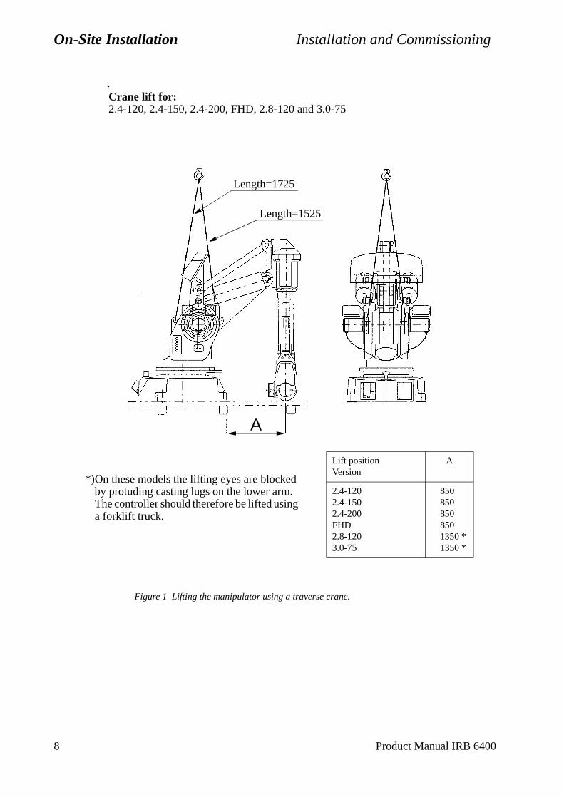
On-Site Installation Installation and Commissioning
.
Figure 1 Lifting the manipulator using a traverse crane.
Crane lift for:2.4-120, 2.4-150, 2.4-200, FHD, 2.8-120 and 3.0-75
A
Lift positionVersion
A
2.4-1202.4-1502.4-200FHD2.8-1203.0-75
8508508508501350 *1350 *
Length=1525
Length=1725
*)On these models the lifting eyes are blocked by protuding casting lugs on the lower arm. The controller should therefore be lifted using a forklift truck.
8 Product Manual IRB 6400

Installation and Commissioning On-Site Installation
Figure 2 Lifting the manipulator with the arm system in the calibration position.
Crane lift, in calibration position for:2.4-120, 2.4-150, 2.4-200, FHD, 2.8-120 and 3.0-75
Min. 700
Product Manual IRB 6400 9
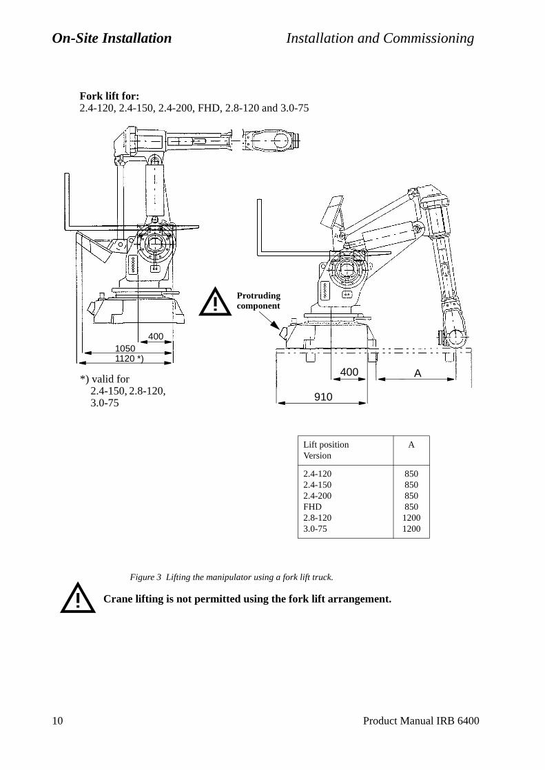
On-Site Installation Installation and Commissioning
Figure 3 Lifting the manipulator using a fork lift truck.
Crane lifting is not permitted using the fork lift arrangement.
Fork lift for:2.4-120, 2.4-150, 2.4-200, FHD, 2.8-120 and 3.0-75
400
1120 *)1050
*) valid for2.4-150, 2.8-120, 3.0-75
A400
910
Lift positionVersion
A
2.4-1202.4-1502.4-200FHD2.8-1203.0-75
850850850850
12001200
Protruding component
10 Product Manual IRB 6400

Installation and Commissioning On-Site Installation
Figure 4 Lifting the manipulator using a crane or a fork lift.
WARNING!Fork lift arrangement on S /2.9-120 must be removed before the robot is taken into operation!
Figure 5 Lifting the manipulator using a fork lift.
Only lift IRB 6400PE/ 2.25-75 with a fork lift (Fork lift arrangement is standard
Crane lift for:S /2.9-120
Fork lift for:S /2.9-120
Fork lift for:PE /2.25-75
400
910
700
Product Manual IRB 6400 11
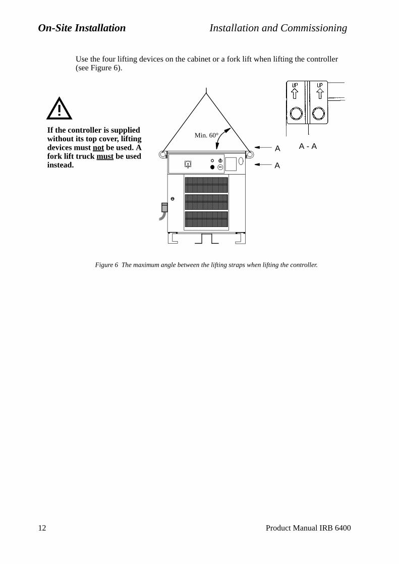
On-Site Installation Installation and Commissioning
Use the four lifting devices on the cabinet or a fork lift when lifting the controller (see Figure 6).
Figure 6 The maximum angle between the lifting straps when lifting the controller.
Min. 60°
A
A A - A
If the controller is supplied without its top cover, lifting devices must not be used. A fork lift truck must be used instead.
12 Product Manual IRB 6400
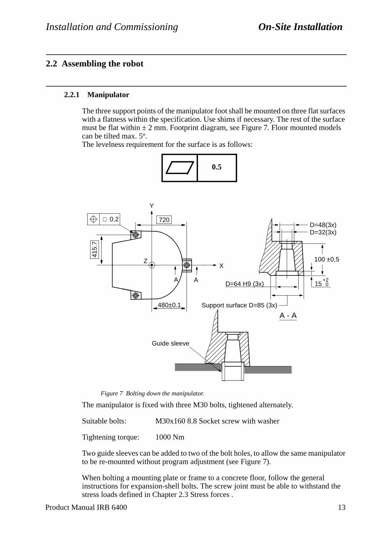
Installation and Commissioning On-Site Installation
els
ulator
the
2.2 Assembling the robot
2.2.1 Manipulator
The three support points of the manipulator foot shall be mounted on three flat surfaces with a flatness within the specification. Use shims if necessary. The rest of the surface must be flat within ± 2 mm. Footprint diagram, see Figure 7. Floor mounted modcan be tilted max. 5o.The levelness requirement for the surface is as follows:
Figure 7 Bolting down the manipulator.
The manipulator is fixed with three M30 bolts, tightened alternately.
Suitable bolts: M30x160 8.8 Socket screw with washer
Tightening torque: 1000 Nm
Two guide sleeves can be added to two of the bolt holes, to allow the same manipto be re-mounted without program adjustment (see Figure 7).
When bolting a mounting plate or frame to a concrete floor, follow the general instructions for expansion-shell bolts. The screw joint must be able to withstand stress loads defined in Chapter 2.3 Stress forces .
0.5
D=64 H9 (3x)
Support surface D=85 (3x)
A
0.2 720
480±0.1
A
∅
415.
7
D=32(3x)D=48(3x)
A - A
X
Y
Z 100 ±0,5
15+2
0
Guide sleeve
Product Manual IRB 6400 13
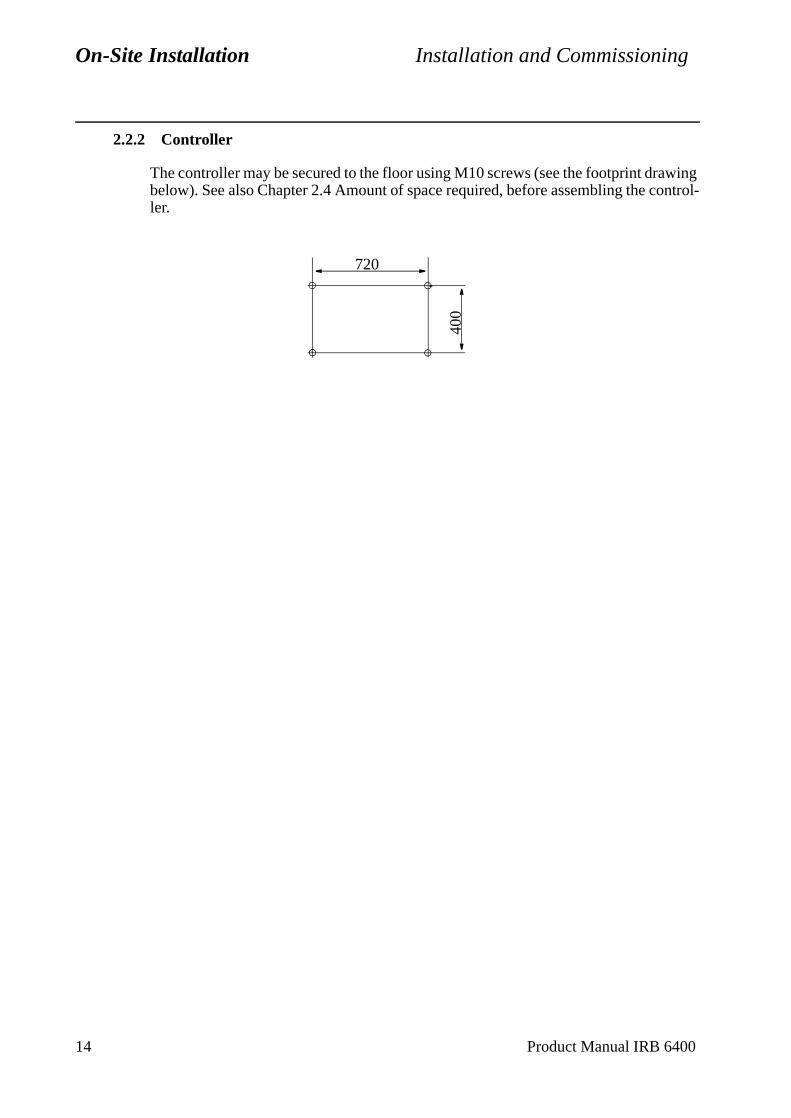
On-Site Installation Installation and Commissioning
2.2.2 Controller
The controller may be secured to the floor using M10 screws (see the footprint drawing below). See also Chapter 2.4 Amount of space required, before assembling the control-ler.
400
720
14 Product Manual IRB 6400
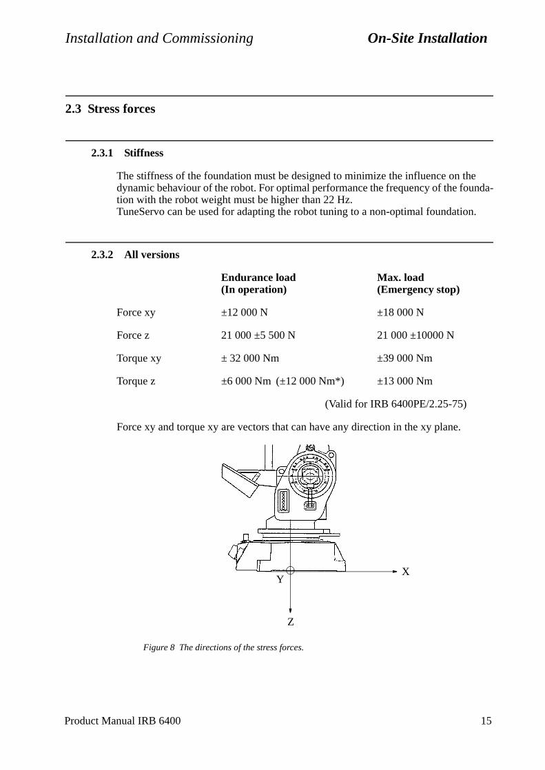
Installation and Commissioning On-Site Installation
2.3 Stress forces
2.3.1 Stiffness
The stiffness of the foundation must be designed to minimize the influence on the dynamic behaviour of the robot. For optimal performance the frequency of the founda-tion with the robot weight must be higher than 22 Hz.TuneServo can be used for adapting the robot tuning to a non-optimal foundation.
2.3.2 All versions
Endurance load Max. load(In operation) (Emergency stop)
Force xy ±12 000 N ±18 000 N
Force z 21 000 ±5 500 N 21 000 ±10000 N
Torque xy ± 32 000 Nm ±39 000 Nm
Torque z ±6 000 Nm (±12 000 Nm*) ±13 000 Nm
(Valid for IRB 6400PE/2.25-75)
Force xy and torque xy are vectors that can have any direction in the xy plane.
Figure 8 The directions of the stress forces.
YX
Z
Product Manual IRB 6400 15
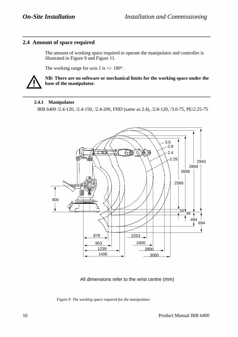
On-Site Installation Installation and Commissioning
5-75
2.4 Amount of space required
The amount of working space required to operate the manipulator and controller is illustrated in Figure 9 and Figure 11.
The working range for axis 1 is +/- 180°.
NB: There are no software or mechanical limits for the working space under the base of the manipulator.
2.4.1 Manipulator
Figure 9 The working space required for the manipulator.
26592849
2943
2.4
2.83.0
94
494694
95312391406
2400
2800
3000
878 2253
53
2589
2.25
900
IRB 6400 /2.4-120, /2.4-150, /2.4-200, FHD (same as 2.4), /2.8-120, /3.0-75, PE/2.2
All dimensions refer to the wrist centre (mm)
16 Product Manual IRB 6400

Installation and Commissioning On-Site Installation
Figure 10 The working space required for the manipulator.
2871
1840
449607
IRB 6400S/ 2.9-120
All dimensions refer to the wrist centre (mm)
Product Manual IRB 6400 17
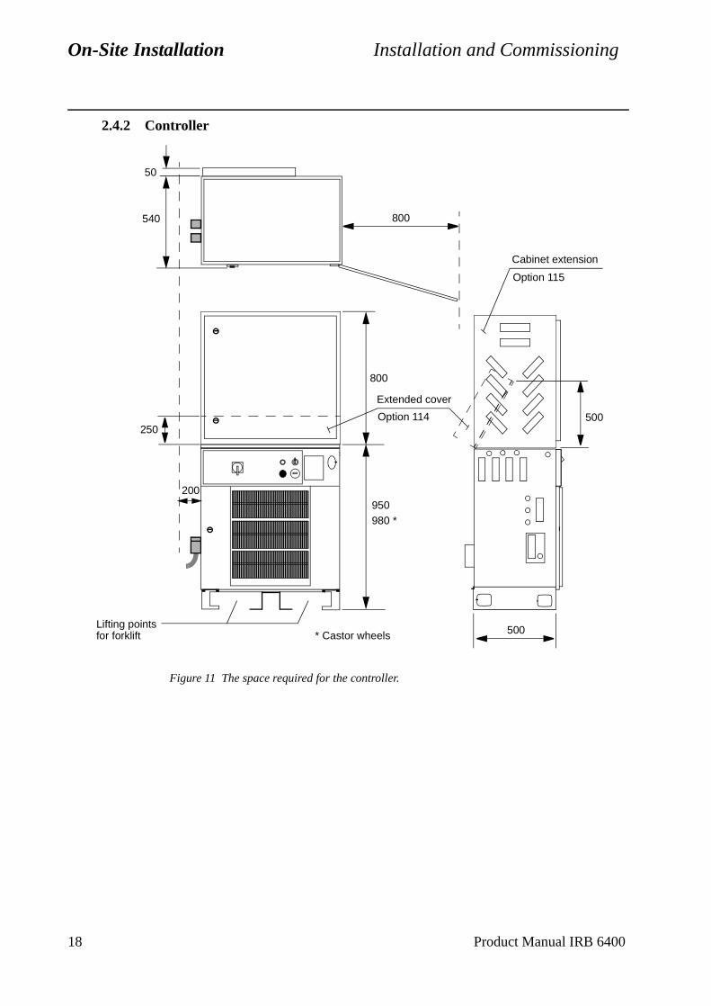
On-Site Installation Installation and Commissioning
2.4.2 Controller
Figure 11 The space required for the controller.
200
50
540
950980 *
500
500
800
Lifting pointsfor forklift * Castor wheels
800
250
Extended cover
Option 114
Cabinet extension
Option 115
18 Product Manual IRB 6400
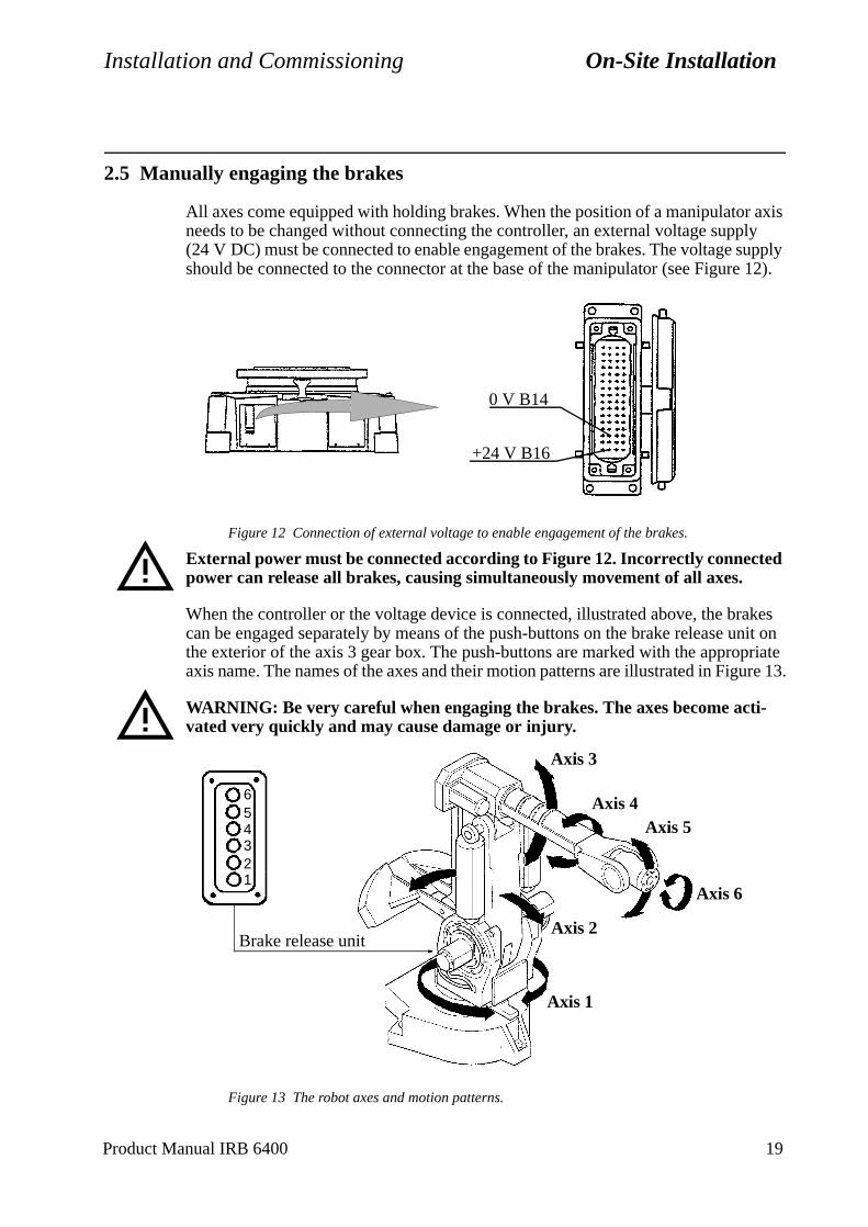
Installation and Commissioning On-Site Installation
2.5 Manually engaging the brakes
All axes come equipped with holding brakes. When the position of a manipulator axis needs to be changed without connecting the controller, an external voltage supply (24 V DC) must be connected to enable engagement of the brakes. The voltage supply should be connected to the connector at the base of the manipulator (see Figure 12).
Figure 12 Connection of external voltage to enable engagement of the brakes.
External power must be connected according to Figure 12. Incorrectly connected power can release all brakes, causing simultaneously movement of all axes.
When the controller or the voltage device is connected, illustrated above, the brakes can be engaged separately by means of the push-buttons on the brake release unit on the exterior of the axis 3 gear box. The push-buttons are marked with the appropriate axis name. The names of the axes and their motion patterns are illustrated in Figure 13.
WARNING: Be very careful when engaging the brakes. The axes become acti-vated very quickly and may cause damage or injury.
Figure 13 The robot axes and motion patterns.
0 V B14
+24 V B16
Axis 2
Axis 3
Axis 4Axis 5
Axis 6
Axis 1
Brake release unit
1
65432
Product Manual IRB 6400 19
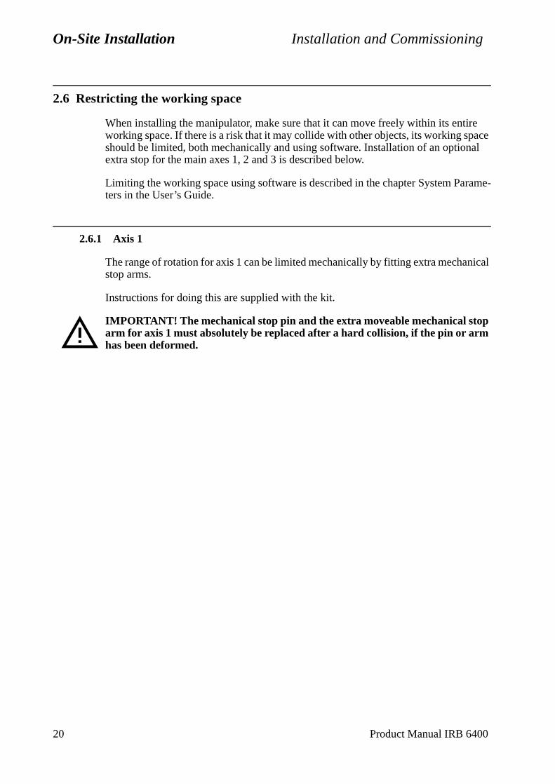
On-Site Installation Installation and Commissioning
ical
2.6 Restricting the working space
When installing the manipulator, make sure that it can move freely within its entire working space. If there is a risk that it may collide with other objects, its working space should be limited, both mechanically and using software. Installation of an optional extra stop for the main axes 1, 2 and 3 is described below.
Limiting the working space using software is described in the chapter System Parame-ters in the User’s Guide.
2.6.1 Axis 1
The range of rotation for axis 1 can be limited mechanically by fitting extra mechanstop arms.
Instructions for doing this are supplied with the kit.
IMPORTANT! The mechanical stop pin and the extra moveable mechanical stop arm for axis 1 must absolutely be replaced after a hard collision, if the pin or arm has been deformed.
20 Product Manual IRB 6400
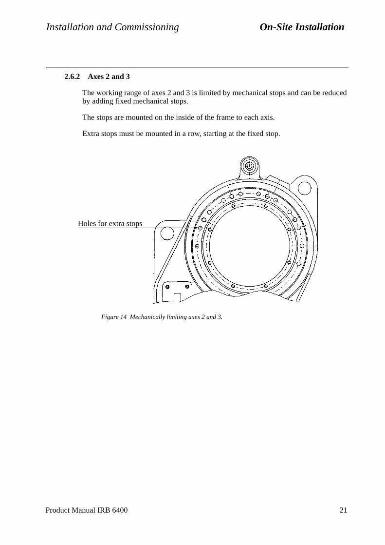
Installation and Commissioning On-Site Installation
2.6.2 Axes 2 and 3
The working range of axes 2 and 3 is limited by mechanical stops and can be reduced by adding fixed mechanical stops.
The stops are mounted on the inside of the frame to each axis.
Extra stops must be mounted in a row, starting at the fixed stop.
Figure 14 Mechanically limiting axes 2 and 3.
Holes for extra stops
Product Manual IRB 6400 21
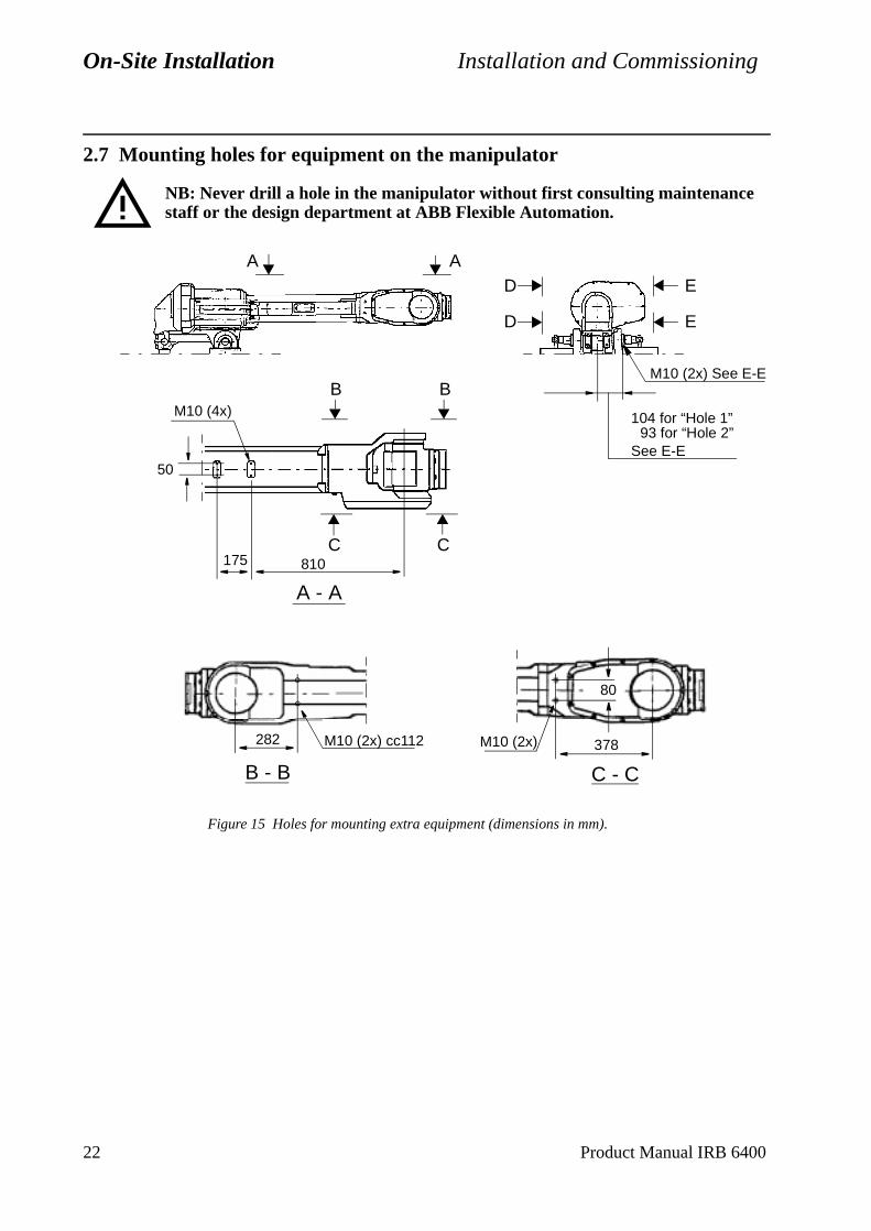
On-Site Installation Installation and Commissioning
2.7 Mounting holes for equipment on the manipulator
NB: Never drill a hole in the manipulator without first consulting maintenance staff or the design department at ABB Flexible Automation.
Figure 15 Holes for mounting extra equipment (dimensions in mm).
A - A
AAD
D
B B
C C
E
E
175 810
50
M10 (4x)
M10 (2x) See E-E
104 for “Hole 1”
B - B C - C
M10 (2x) cc112282
80
M10 (2x) 378
93 for “Hole 2”See E-E
22 Product Manual IRB 6400
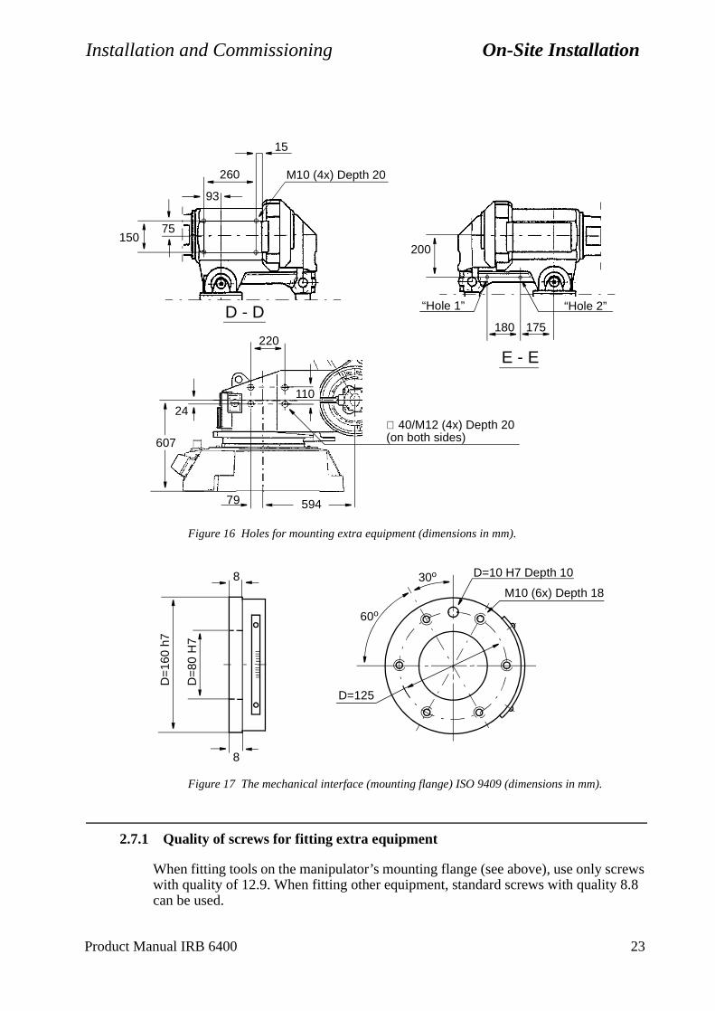
Installation and Commissioning On-Site Installation
rews .8
Figure 16 Holes for mounting extra equipment (dimensions in mm).
Figure 17 The mechanical interface (mounting flange) ISO 9409 (dimensions in mm).
2.7.1 Quality of screws for fitting extra equipment
When fitting tools on the manipulator’s mounting flange (see above), use only scwith quality of 12.9. When fitting other equipment, standard screws with quality 8can be used.
D - D
E - E
93
260 M10 (4x) Depth 20
75150
200
“Hole 2”
175180
∅ 40/M12 (4x) Depth 20(on both sides)
59479
220
110
607
24
“Hole 1”
15
30o
60o
D=10 H7 Depth 10
M10 (6x) Depth 18
D=
160
h7
D=
80 H
7
D=125
8
8
Product Manual IRB 6400 23
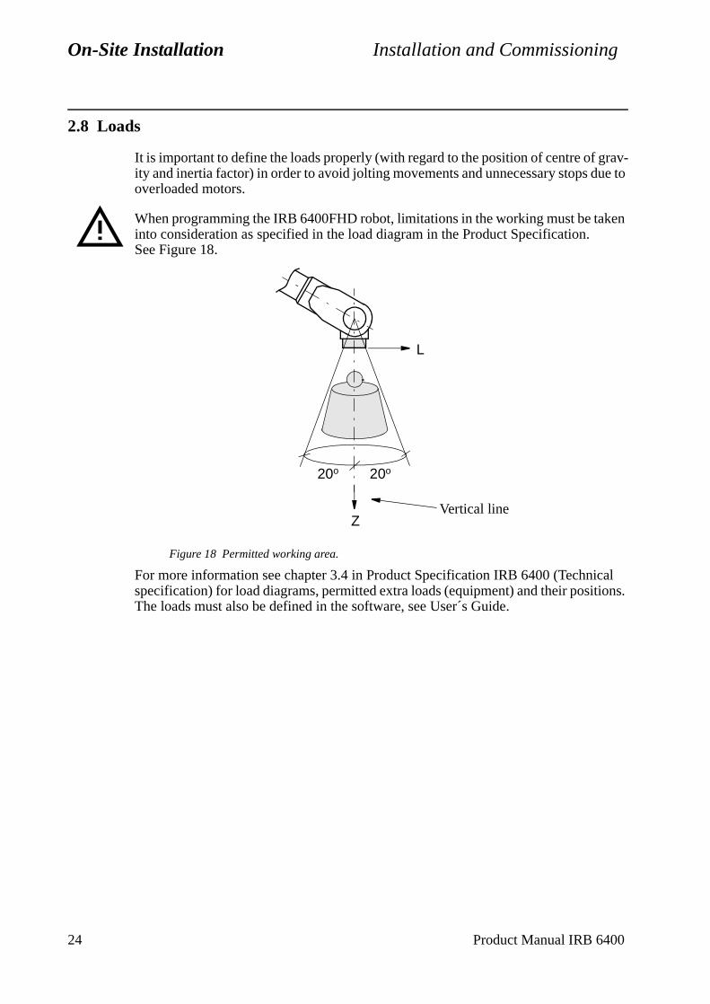
On-Site Installation Installation and Commissioning
2.8 Loads
It is important to define the loads properly (with regard to the position of centre of grav-ity and inertia factor) in order to avoid jolting movements and unnecessary stops due to overloaded motors.
When programming the IRB 6400FHD robot, limitations in the working must be taken into consideration as specified in the load diagram in the Product Specification. See Figure 18.
Figure 18 Permitted working area.
For more information see chapter 3.4 in Product Specification IRB 6400 (Technical specification) for load diagrams, permitted extra loads (equipment) and their positions. The loads must also be defined in the software, see User´s Guide.
L
20o 20o
ZVertical line
24 Product Manual IRB 6400
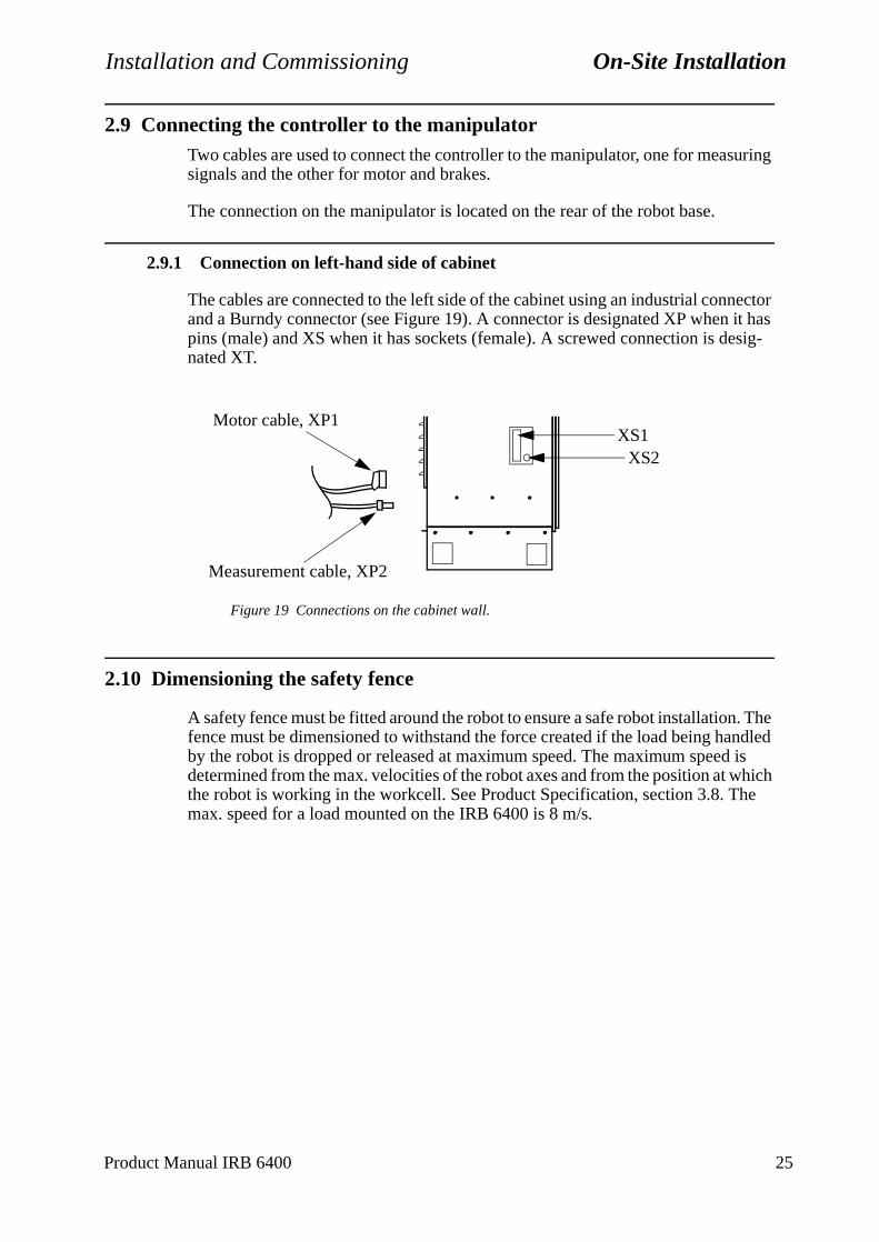
Installation and Commissioning On-Site Installation
2.9 Connecting the controller to the manipulatorTwo cables are used to connect the controller to the manipulator, one for measuring signals and the other for motor and brakes.
The connection on the manipulator is located on the rear of the robot base.
2.9.1 Connection on left-hand side of cabinet
The cables are connected to the left side of the cabinet using an industrial connector and a Burndy connector (see Figure 19). A connector is designated XP when it has pins (male) and XS when it has sockets (female). A screwed connection is desig-nated XT.
Figure 19 Connections on the cabinet wall.
2.10 Dimensioning the safety fence
A safety fence must be fitted around the robot to ensure a safe robot installation. The fence must be dimensioned to withstand the force created if the load being handled by the robot is dropped or released at maximum speed. The maximum speed is determined from the max. velocities of the robot axes and from the position at which the robot is working in the workcell. See Product Specification, section 3.8. The max. speed for a load mounted on the IRB 6400 is 8 m/s.
XS2XS1
Motor cable, XP1
Measurement cable, XP2
Product Manual IRB 6400 25
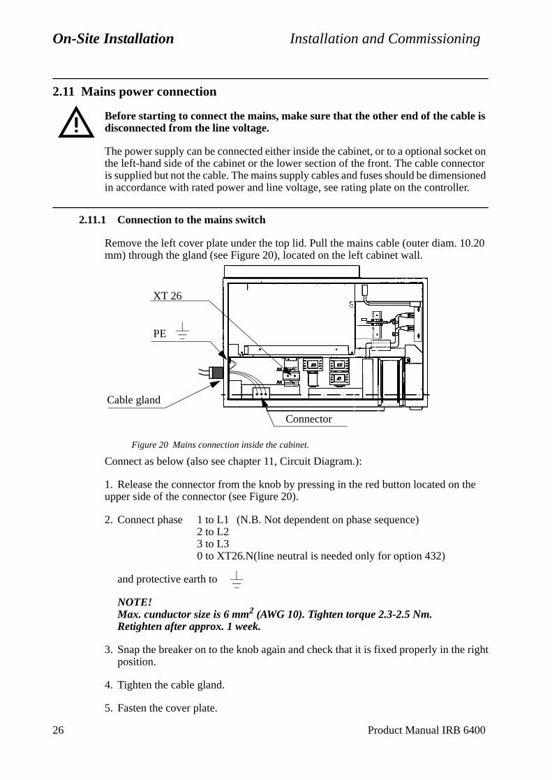
On-Site Installation Installation and Commissioning
2.11 Mains power connection
Before starting to connect the mains, make sure that the other end of the cable is disconnected from the line voltage.
The power supply can be connected either inside the cabinet, or to a optional socket on the left-hand side of the cabinet or the lower section of the front. The cable connector is supplied but not the cable. The mains supply cables and fuses should be dimensioned in accordance with rated power and line voltage, see rating plate on the controller.
2.11.1 Connection to the mains switch
Remove the left cover plate under the top lid. Pull the mains cable (outer diam. 10.20 mm) through the gland (see Figure 20), located on the left cabinet wall.
Figure 20 Mains connection inside the cabinet.
Connect as below (also see chapter 11, Circuit Diagram.):
1. Release the connector from the knob by pressing in the red button located on the upper side of the connector (see Figure 20).
2. Connect phase 1 to L1 (N.B. Not dependent on phase sequence)2 to L23 to L30 to XT26.N(line neutral is needed only for option 432)
and protective earth to
NOTE! Max. cunductor size is 6 mm2 (AWG 10). Tighten torque 2.3-2.5 Nm. Retighten after approx. 1 week.
3. Snap the breaker on to the knob again and check that it is fixed properly in the rightposition.
4. Tighten the cable gland.
5. Fasten the cover plate.
PE
Cable gland
Connector
XT 26
26 Product Manual IRB 6400
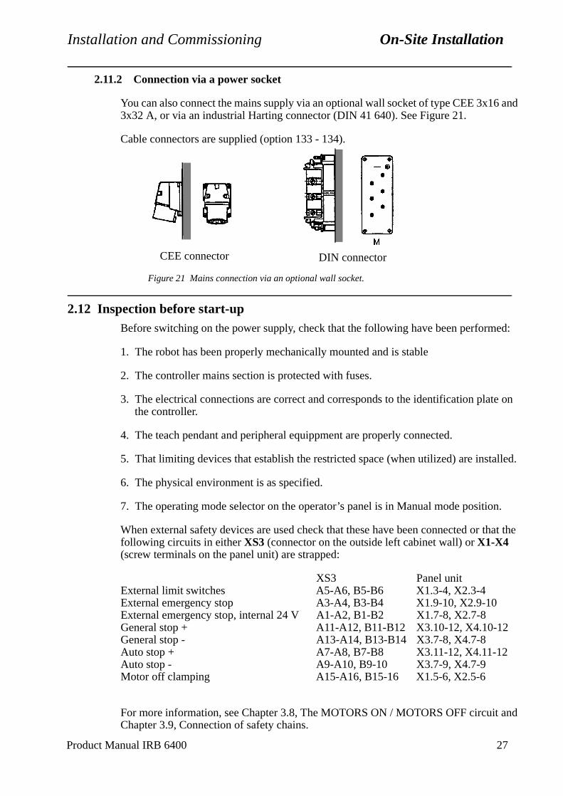
Installation and Commissioning On-Site Installation
n.
that the
and
2.11.2 Connection via a power socket
You can also connect the mains supply via an optional wall socket of type CEE 3x16 and 3x32 A, or via an industrial Harting connector (DIN 41 640). See Figure 21.
Cable connectors are supplied (option 133 - 134).
Figure 21 Mains connection via an optional wall socket.
2.12 Inspection before start-upBefore switching on the power supply, check that the following have been performed:
1. The robot has been properly mechanically mounted and is stable
2. The controller mains section is protected with fuses.
3. The electrical connections are correct and corresponds to the identification plate on the controller.
4. The teach pendant and peripheral equippment are properly connected.
5. That limiting devices that establish the restricted space (when utilized) are installed.
6. The physical environment is as specified.
7. The operating mode selector on the operator’s panel is in Manual mode positio
When external safety devices are used check that these have been connected or following circuits in either XS3 (connector on the outside left cabinet wall) or X1-X4 (screw terminals on the panel unit) are strapped:
XS3 Panel unitExternal limit switches A5-A6, B5-B6 X1.3-4, X2.3-4External emergency stop A3-A4, B3-B4 X1.9-10, X2.9-10External emergency stop, internal 24 V A1-A2, B1-B2 X1.7-8, X2.7-8General stop + A11-A12, B11-B12 X3.10-12, X4.10-12General stop - A13-A14, B13-B14 X3.7-8, X4.7-8Auto stop + A7-A8, B7-B8 X3.11-12, X4.11-12Auto stop - A9-A10, B9-10 X3.7-9, X4.7-9Motor off clamping A15-A16, B15-16 X1.5-6, X2.5-6
For more information, see Chapter 3.8, The MOTORS ON / MOTORS OFF circuitChapter 3.9, Connection of safety chains.
CEE connector DIN connector
Product Manual IRB 6400 27
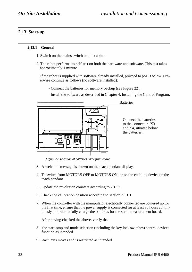
On-Site Installation Installation and Commissioning
2.13 Start-up
2.13.1 General
1. Switch on the mains switch on the cabinet.
2. The robot performs its self-test on both the hardware and software. This test takes approximately 1 minute.
If the robot is supplied with software already installed, proceed to pos. 3 below. Oth-erwise continue as follows (no software installed):
- Connect the batteries for memory backup (see Figure 22).
- Install the software as described in Chapter 4, Installing the Control Program.
Figure 22 Location of batteries, view from above.
3. A welcome message is shown on the teach pendant display.
4. To switch from MOTORS OFF to MOTORS ON, press the enabling device on the teach pendant.
5. Update the revolution counters according to 2.13.2.
6. Check the calibration position according to section 2.13.3.
7. When the controller with the manipulator electrically connected are powered up for the first time, ensure that the power supply is connected for at least 36 hours contin-uously, in order to fully charge the batteries for the serial measurement board.
After having checked the above, verify that
8. the start, stop and mode selection (including the key lock switches) control devices function as intended.
9. each axis moves and is restricted as intended.
Batteries
Connect the batteries to the connectors X3 and X4, situated below the batteries.
28 Product Manual IRB 6400
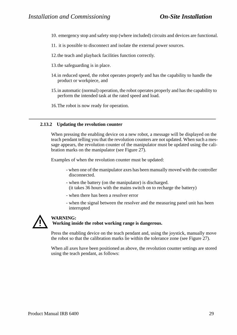
Installation and Commissioning On-Site Installation
10. emergency stop and safety stop (where included) circuits and devices are functional.
11. it is possible to disconnect and isolate the external power sources.
12.the teach and playback facilities function correctly.
13.the safeguarding is in place.
14.in reduced speed, the robot operates properly and has the capability to handle the product or workpiece, and
15.in automatic (normal) operation, the robot operates properly and has the capability to perform the intended task at the rated speed and load.
16.The robot is now ready for operation.
2.13.2 Updating the revolution counter
When pressing the enabling device on a new robot, a message will be displayed on the teach pendant telling you that the revolution counters are not updated. When such a mes-sage appears, the revolution counter of the manipulator must be updated using the cali-bration marks on the manipulator (see Figure 27).
Examples of when the revolution counter must be updated:
- when one of the manipulator axes has been manually moved with the controller disconnected.
- when the battery (on the manipulator) is discharged. (it takes 36 hours with the mains switch on to recharge the battery)
- when there has been a resolver error
- when the signal between the resolver and the measuring panel unit has been interrupted
WARNING: Working inside the robot working range is dangerous.
Press the enabling device on the teach pendant and, using the joystick, manually move the robot so that the calibration marks lie within the tolerance zone (see Figure 27).
When all axes have been positioned as above, the revolution counter settings are stored using the teach pendant, as follows:
Product Manual IRB 6400 29
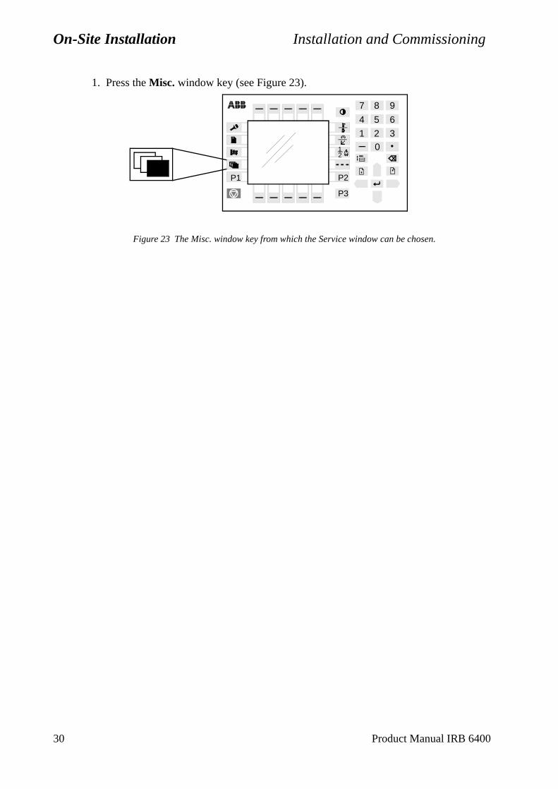
On-Site Installation Installation and Commissioning
1. Press the Misc. window key (see Figure 23).
Figure 23 The Misc. window key from which the Service window can be chosen.
21
2 30
1
4 5 6
7 8 9
P3
P1 P2
30 Product Manual IRB 6400
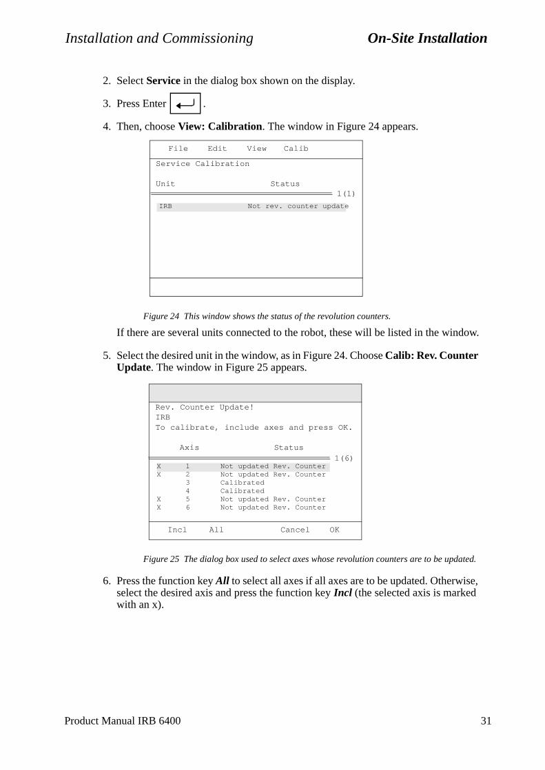
Installation and Commissioning On-Site Installation
2. Select Service in the dialog box shown on the display.
3. Press Enter .
4. Then, choose View: Calibration. The window in Figure 24 appears.
Figure 24 This window shows the status of the revolution counters.
If there are several units connected to the robot, these will be listed in the window.
5. Select the desired unit in the window, as in Figure 24. Choose Calib: Rev. Counter Update. The window in Figure 25 appears.
Figure 25 The dialog box used to select axes whose revolution counters are to be updated.
6. Press the function key All to select all axes if all axes are to be updated. Otherwise, select the desired axis and press the function key Incl (the selected axis is marked with an x).
IRB Not rev. counter update
File Edit View Calib
1(1)
Service Calibration
Unit Status
X 1 Not updated Rev. CounterX 2 Not updated Rev. Counter
3 Calibrated4 Calibrated
X 5 Not updated Rev. CounterX 6 Not updated Rev. Counter
Incl All Cancel OK
1(6)
Rev. Counter Update!IRBTo calibrate, include axes and press OK.
Axis Status
Product Manual IRB 6400 31
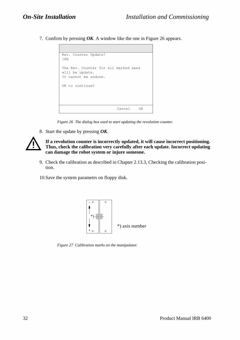
On-Site Installation Installation and Commissioning
7. Confirm by pressing OK. A window like the one in Figure 26 appears.
Figure 26 The dialog box used to start updating the revolution counter.
8. Start the update by pressing OK.
If a revolution counter is incorrectly updated, it will cause incorrect positioning. Thus, check the calibration very carefully after each update. Incorrect updating can damage the robot system or injure someone.
9. Check the calibration as described in Chapter 2.13.3, Checking the calibration posi-tion.
10.Save the system parametrs on floppy disk.
Figure 27 Calibration marks on the manipulator.
Cancel OK
Rev. Counter Update!IRB
The Rev. Counter for all marked axes will be update.It cannot be undone.
OK to continue?
+
-
*)
*) axis number
32 Product Manual IRB 6400
Installation and Commissioning On-Site Installation
make
2.13.3 Checking the calibration position
There are two ways to check the calibration position and they are described below.
Using the diskette, Controller Parameters:
Run the program \ SERVICE \ CALIBRAT \ CAL 6400 on the diskette, follow intruc-tions displayed on the teach pendant. When the robot stops, switch to MOTORS OFF. Check that the calibration marks for each axis are at the same level, see Figure 27. If they are not, the setting of the revolution counters must be repeated.
Using the Jogging window on the teach pendant:
Open the Jogging window and choose running axis-by-axis. Using the joystick, move the robot so that the read-out of the positions is equal to zero. Check that the cal-ibration marks for each axis are at the same level, see Figure 27. If they are not, the setting of the revolution counters must be repeated.
2.13.4 Alternative calibration positions
See chapter 12, Repairs.
2.13.5 Operating the robot
Starting and operating the robot is described in the User’s Guide. Before start-up,sure that the robot cannot collide with any other objects in the working space.
Product Manual IRB 6400 33

On-Site Installation Installation and Commissioning
34 Product Manual IRB 6400

Installation and Commissioning Connecting Signals
.
I/O).
nals
be
-
ABB r elec-
d for
con-
3 Connecting Signals
3.1 Signal classes
Power – supplies external motors and brakes.
Control signals – digital operating and data signals (digital I/O, safety stops, etc.)
Measuring signals – analog measuring and control signals (resolver and analog
Data communication signals – field bus connection, computer link.
Different rules apply to the different classes when selecting and laying cable. Sigfrom different classes must not be mixed.
3.2 Selecting cables
All cables laid in the controller must be capable of withstanding 70o C. In addition, the following rules apply to the cables of certain signal classes:
Power signals -Shielded cable with an area of at least 0.75 mm2 or AWG 18. Note that any local standards and regulations concerning insulation and area must alwayscomplied with.
Control signals – Shielded cable.
Measuring signals – Shielded cable with twisted pair conductors.
Data communication signals – Shielded cable with twisted pair conductors. A specific cable should be used for field bus connections.
CAN bus with DeviceNet for distributing I/O units;
Thin cable according to DeviceNet specification release 1.2, must be used, e.g. article no. 3HAB 8277-1. The cable is screened and has four conductors, two fotronic supply and two for signal transmission.Note that a separate cable for supply of I/O load is required.
Allen-Bradley Remote I/O;
Cables according to Allen-Bradley specification, e.g. “Blue hose”, should be useconnections between DSQC 350 and the Allen-Bradley PLC bus.
Interbus-S:
Cables according to Phönix specification, e.g. “Green type”, should be used for nections between the DSQC 351 and external Interbus-S bus.
Product Manual IRB 6400 35
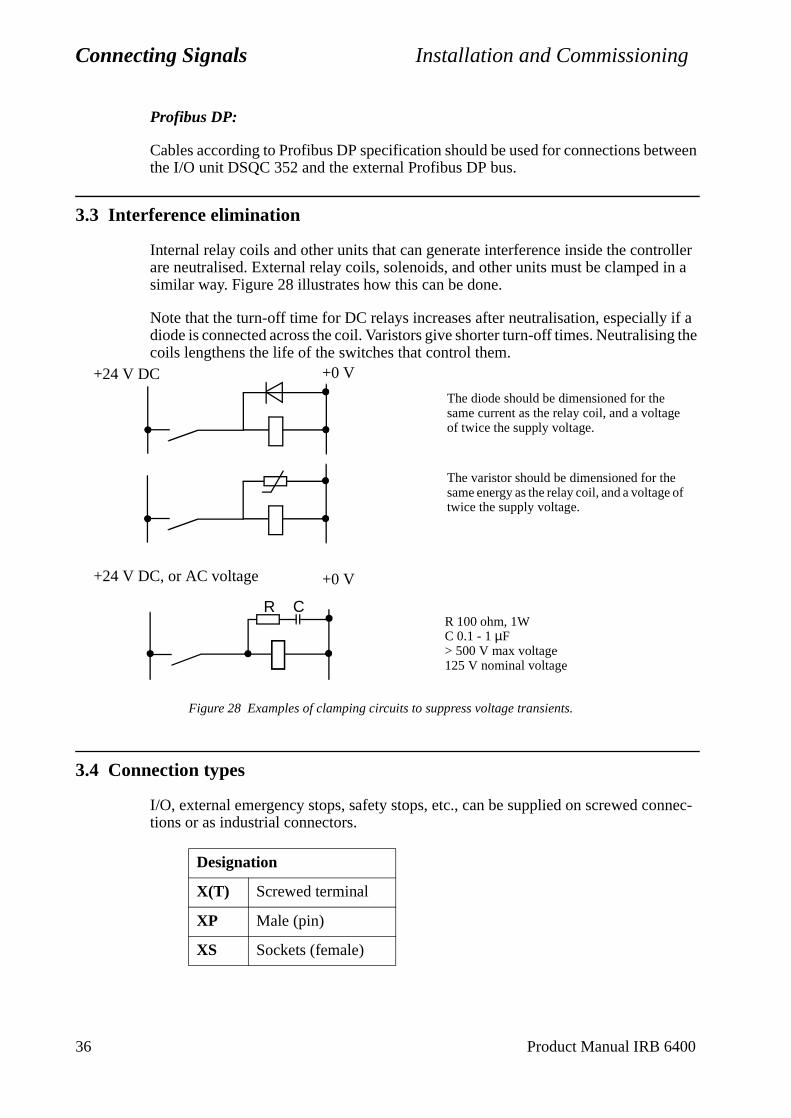
Connecting Signals Installation and Commissioning
36 Product Manual IRB 6400
Profibus DP:
Cables according to Profibus DP specification should be used for connections between the I/O unit DSQC 352 and the external Profibus DP bus.
3.3 Interference elimination
Internal relay coils and other units that can generate interference inside the controller are neutralised. External relay coils, solenoids, and other units must be clamped in a similar way. Figure 28 illustrates how this can be done.
Note that the turn-off time for DC relays increases after neutralisation, especially if a diode is connected across the coil. Varistors give shorter turn-off times. Neutralising the coils lengthens the life of the switches that control them.
Figure 28 Examples of clamping circuits to suppress voltage transients.
3.4 Connection types
I/O, external emergency stops, safety stops, etc., can be supplied on screwed connec-tions or as industrial connectors.
Designation
X(T) Screwed terminal
XP Male (pin)
XS Sockets (female)
+0 V
+24 V DC, or AC voltage +0 V
+24 V DC
The diode should be dimensioned for the same current as the relay coil, and a voltage of twice the supply voltage.
R 100 ohm, 1WC 0.1 - 1 µF> 500 V max voltage125 V nominal voltage
R C
The varistor should be dimensioned for the same energy as the relay coil, and a voltage of twice the supply voltage.
Installation and Commissioning Connecting Signals
3.5 Connections
Detailed information about connection locations and functions will be found in chapter 11, Circuit Diagram.
3.5.1 To screw terminal
Panel unit and I/O units are provided wiyh keyed screw terminals for cables with an area between 0.25 and 1.5 mm2. A maximum of two cables may be used in any one connection. The cable screen must be connected to the cabinet wall using EMC. It should be noted that the screen must continue right up to the screw terminal.The installation should comply with the IP54 (NEMA 12) protective standard.
Bend unused conductors backwards and attach them to the cable using a clasp, for example. In order to prevent interference, ensure that such conductors are not con-nected at the other end of the cable (antenna effect). In environments with much inter-ference, disconnected conductors should be grounded (0 V) at both ends.
3.5.2 To connectors (option)
Industrial connectors with 4x16 pins for contact crimping (complies with DIN 43652) can be found on the left-hand side or front of the cabinet (depending on the customer order) See Figure 29 and Figure 20.
In each industrial connector there is space for four rows of 16 conductors with a max-imum conductor area of 1.5 mm2. The pull-relief clamp must be used when connecting the shield to the case.
The manipulator arm is equipped with round Burndy/Framatome connectors (customer connector not included).
Bend unused conductors backwards and attach them to the cable using a clasp, for example. In order to prevent interference, ensure that such conductors are not con-nected at the other end of the cable (antenna effect). In environments with much inter-ference, disconnected conductors should be grounded (0 V) at both ends.
When contact crimping industrial connectors, the following applies:
Using special tongs, press a pin or socket on to each non-insulated conductor.The pin can then be snapped into the actual contact.Push the pin into the connector until it locks.
Also, see instructions from contact supplier.
A special extractor tool must be used to remove pins from industrial connectors.
When two conductors must be connected to the same pin, both of them are pressed into the same pin. A maximum of two conductors may be pressed into any one pin.
Product Manual IRB 6400 37
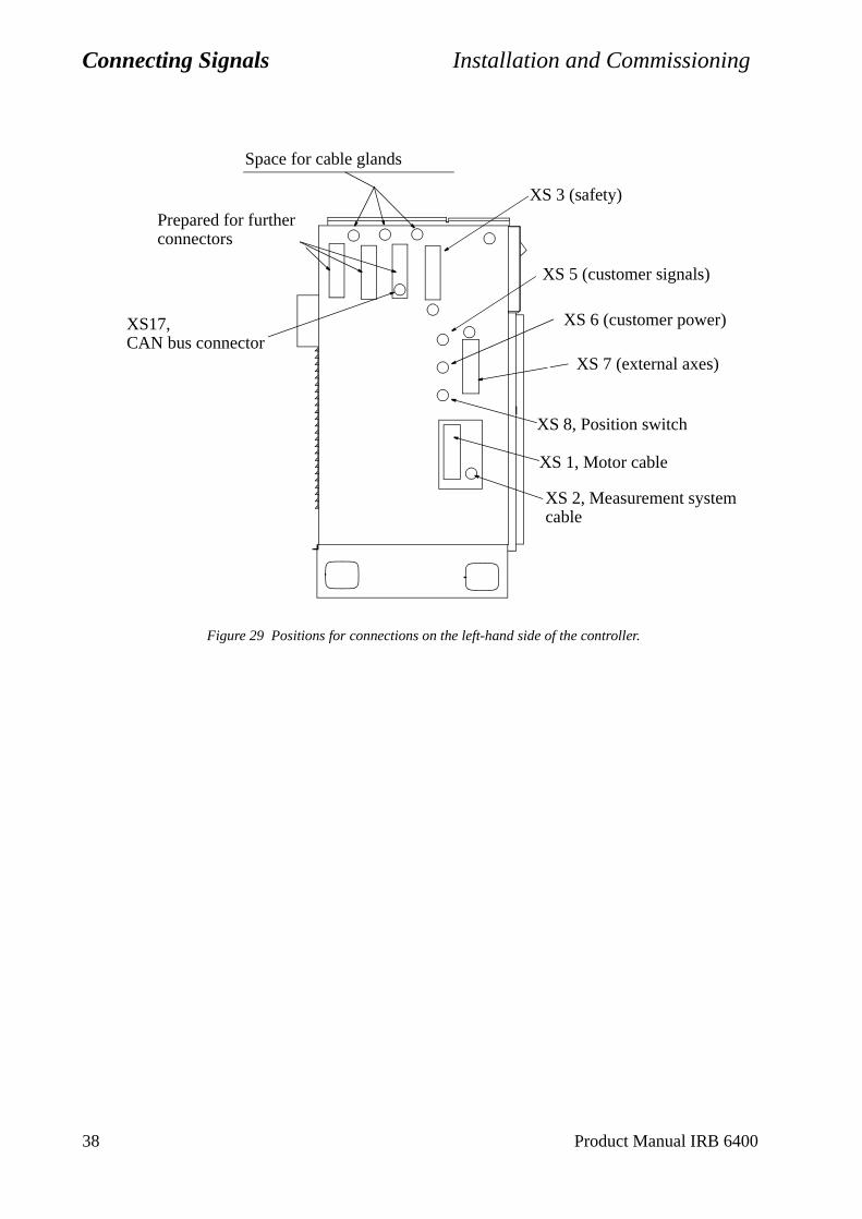
Connecting Signals Installation and Commissioning
Figure 29 Positions for connections on the left-hand side of the controller.
XS 3 (safety)
XS 8, Position switch
XS 5 (customer signals)
XS 6 (customer power)
XS 7 (external axes)
Space for cable glands
Prepared for further connectors
XS 1, Motor cable
XS 2, Measurement system cable
XS17,CAN bus connector
38 Product Manual IRB 6400
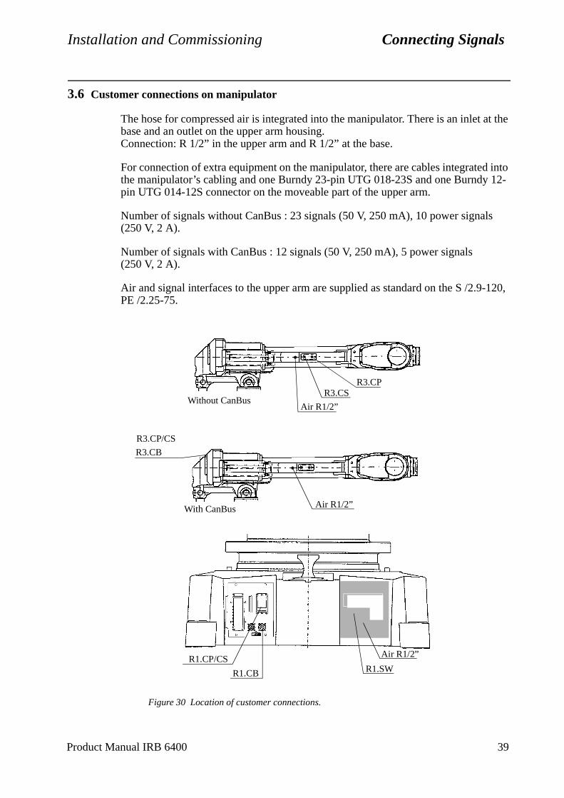
Installation and Commissioning Connecting Signals
d into 12-
s
-120,
3.6 Customer connections on manipulator
The hose for compressed air is integrated into the manipulator. There is an inlet at the base and an outlet on the upper arm housing.Connection: R 1/2” in the upper arm and R 1/2” at the base.
For connection of extra equipment on the manipulator, there are cables integratethe manipulator’s cabling and one Burndy 23-pin UTG 018-23S and one Burndypin UTG 014-12S connector on the moveable part of the upper arm.
Number of signals without CanBus : 23 signals (50 V, 250 mA), 10 power signal(250 V, 2 A).
Number of signals with CanBus : 12 signals (50 V, 250 mA), 5 power signals (250 V, 2 A).
Air and signal interfaces to the upper arm are supplied as standard on the S /2.9PE /2.25-75.
Figure 30 Location of customer connections.
Air R1/2”
R3.CP
Air R1/2”
R1.CP/CS
R1.CB
R3.CS
Air R1/2”
R3.CP/CS
R3.CB
Without CanBus
With CanBus
R1.SW
Product Manual IRB 6400 39
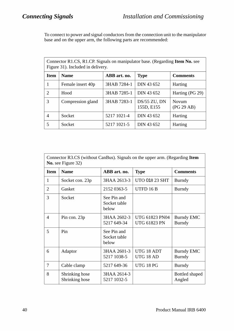
Connecting Signals Installation and Commissioning
To connect to power and signal conductors from the connection unit to the manipulator base and on the upper arm, the following parts are recommended:
Connector R1.CS, R1.CP. Signals on manipulator base. (Regarding Item No. see Figure 31). Included in delivery.
Item Name ABB art. no. Type Comments
1 Female insert 40p 3HAB 7284-1 DIN 43 652 Harting
2 Hood 3HAB 7285-1 DIN 43 652 Harting (PG 29)
3 Compression gland 3HAB 7283-1 DS/55 ZU, DN 155D, E155
Novum (PG 29 AB)
4 Socket 5217 1021-4 DIN 43 652 Harting
5 Socket 5217 1021-5 DIN 43 652 Harting
Connector R3.CS (without CanBus). Signals on the upper arm. (Regarding Item No. see Figure 32)
Item Name ABB art. no. Type Comments
1 Socket con. 23p 3HAA 2613-3 UTO 018 23 SHT Burndy
2 Gasket 2152 0363-5 UTFD 16 B Burndy
3 Socket See Pin and Socket table below
4 Pin con. 23p 3HAA 2602-35217 649-34
UTG 61823 PN04UTG 61823 PN
Burndy EMCBurndy
5 Pin See Pin and Socket table below
6 Adaptor 3HAA 2601-35217 1038-5
UTG 18 ADTUTG 18 AD
Burndy EMCBurndy
7 Cable clamp 5217 649-36 UTG 18 PG Burndy
8 Shrinking hoseShrinking hose
3HAA 2614-35217 1032-5
Bottled shapedAngled
40 Product Manual IRB 6400
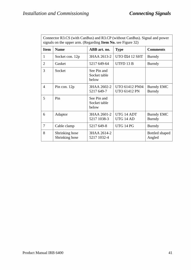
Installation and Commissioning Connecting Signals
Product Manual IRB 6400 41
Connector R3.CS (with CanBus) and R3.CP (without CanBus). Signal and power signals on the upper arm. (Regarding Item No. see Figure 32)
Item Name ABB art. no. Type Comments
1 Socket con. 12p 3HAA 2613-2 UTO 014 12 SHT Burndy
2 Gasket 5217 649-64 UTFD 13 B Burndy
3 Socket See Pin and Socket table below
4 Pin con. 12p 3HAA 2602-25217 649-7
UTO 61412 PN04UTO 61412 PN
Burndy EMCBurndy
5 Pin See Pin and Socket table below
6 Adaptor 3HAA 2601-25217 1038-3
UTG 14 ADTUTG 14 AD
Burndy EMCBurndy
7 Cable clamp 5217 649-8 UTG 14 PG Burndy
8 Shrinking hoseShrinking hose
3HAA 2614-25217 1032-4
Bottled shapedAngled
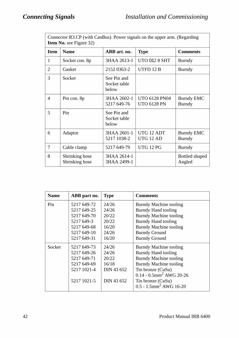
Connecting Signals Installation and Commissioning
Connector R3.CP (with CanBus). Power signals on the upper arm. (Regarding Item No. see Figure 32)
Item Name ABB art. no. Type Comments
1 Socket con. 8p 3HAA 2613-1 UTO 012 8 SHT Burndy
2 Gasket 2152 0363-2 UTFD 12 B Burndy
3 Socket See Pin and Socket table below
4 Pin con. 8p 3HAA 2602-15217 649-76
UTO 6128 PN04UTO 6128 PN
Burndy EMCBurndy
5 Pin See Pin and Socket table below
6 Adaptor 3HAA 2601-15217 1038-2
UTG 12 ADTUTG 12 AD
Burndy EMCBurndy
7 Cable clamp 5217 649-79 UTG 12 PG Burndy
8 Shrinking hoseShrinking hose
3HAA 2614-13HAA 2499-1
Bottled shapedAngled
Name ABB part no. Type Comments
Pin 5217 649-725217 649-255217 649-705217 649-35217 649-685217 649-105217 649-31
24/2624/2620/2220/2216/2024/2616/20
Burndy Machine toolingBurndy Hand toolingBurndy Machine toolingBurndy Hand toolingBurndy Machine toolingBurndy GroundBurndy Ground
Socket 5217 649-735217 649-265217 649-715217 649-695217 1021-4
5217 1021-5
24/2624/2620/2216/18DIN 43 652
DIN 43 652
Burndy Machine toolingBurndy Hand toolingBurndy Machine toolingBurndy Machine toolingTin bronze (CuSu)0.14 - 0.5mm2 AWG 20-26Tin bronze (CuSu)0.5 - 1.5mm2 AWG 16-20
42 Product Manual IRB 6400
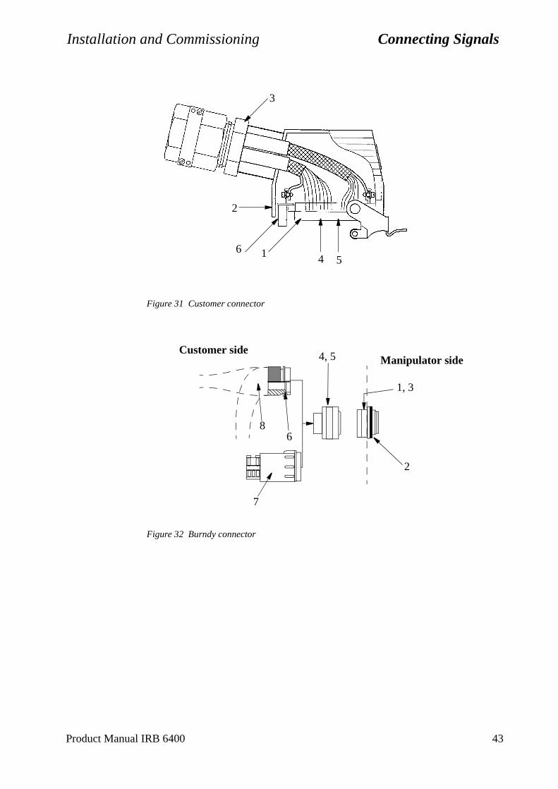
Installation and Commissioning Connecting Signals
Figure 31 Customer connector
Figure 32 Burndy connector
1 4 5
2
3
6
Customer sideManipulator side
68
1, 3
4, 5
7
2
Product Manual IRB 6400 43
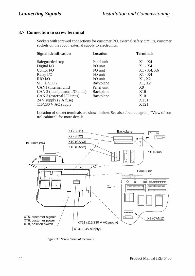
Connecting Signals Installation and Commissioning
con-
3.7 Connection to screw terminal
Sockets with screwed connections for customer I/O, external safety circuits, customer sockets on the robot, external supply to electronics.
Signal identification Location Terminals
Safeguarded stop Panel unit X1 - X4Digital I/O I/O unit X1 - X4Combi I/O I/O unit X1 - X4, X6Relay I/O I/O unit X1 - X4RIO I/O I/O unit X1, X2SIO 1, SIO 2 Backplane X1, X2CAN1 (internal unit) Panel unit X9CAN 2 (manipulator, I/O units) Backplane X16CAN 3 (external I/O units) Backplane X1024 V supply (2 A fuse) XT31115/230 V AC supply XT21
Location of socket terminals are shown below. See also circuit diagram, “View oftrol cabinet”, for more details.
Figure 33 Screw terminal locations.
I/O units (x4)
XT5, customer signalsXT6, customer powerXT8, position switch
XT31 (24V supply)
Backplane
X10 (CAN3)
X16 (CAN2)
X1 (SIO1)
X2 (SIO2)
X5 X8 X6 CONTROL PANEL
WARNINGREMOVE JUMPERS BEFORE CONNECTINGANY EXTERNAL EQUIPMENT
EN MS NS ES1 ES2 GS1 AS2AS1GS2
Panel unit
X1 - 4
XT21 (115/230 V ACsupply)X9 (CAN1))
alt. D-sub
44 Product Manual IRB 6400
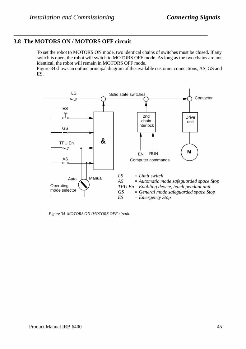
Installation and Commissioning Connecting Signals
3.8 The MOTORS ON / MOTORS OFF circuit
To set the robot to MOTORS ON mode, two identical chains of switches must be closed. If any switch is open, the robot will switch to MOTORS OFF mode. As long as the two chains are not identical, the robot will remain in MOTORS OFF mode.Figure 34 shows an outline principal diagram of the available customer connections, AS, GS and ES.
Figure 34 MOTORS ON /MOTORS OFF circuit.
Manual LS = Limit switchAS = Automatic mode safeguarded space StopTPU En= Enabling device, teach pendant unitGS = General mode safeguarded space StopES = Emergency Stop
2ndchain
interlock
AS
GS
Auto
M
Driveunit
ContactorSolid state switchesLS
TPU En
ES
EN RUN
Computer commands
&
Operating mode selector
Product Manual IRB 6400 45
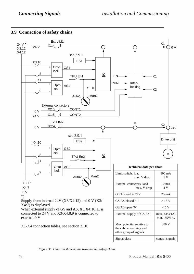
Connecting Signals Installation and Commissioning
46 Product Manual IRB 6400
3.9 Connection of safety chains
Figure 35 Diagram showing the two-channel safety chain.
Man1Auto1
Man2Auto2
X1:4
X3:10
X2:4
X4:10
X1:5
X2:5
X3:7 *
9
3
11
8
6
6
9
11
8
3
Ext LIM2
External contactors
Ext LIM1
GS1
AS1
TPU En1
ES1
Optoisol.
Optoisol.
& EN
RUN Inter-locking
K1
K2
K10 V
K2
M
Drive unit
AS2
GS2
ES2
TPU En2 &
24 V *
see 3.9.1
see 3.9.1
Optoisol.
Optoisol.
24 V
24 V
CONT1
CONT2
*)Supply from internal 24V (X3/X4:12) and 0 V (X3/X4:7) is displayed.When external supply of GS and AS, X3/X4:10,11 is connected to 24 V and X3/X4:8,9 is connected to external 0 V
X1-X4 connection tables, see section 3.10.
24V
X4:70 V
+
+
-
-
0 V
0 V
+
+
-
-
X3:12X4:12
Technical data per chain
Limit switch: loadmax. V drop
300 mA1 V
External contactors: loadmax. V drop
10 mA4 V
GS/AS load at 24V 25 mA
GS/AS closed “1” > 18 V
GS/AS open “0” < 5 V
External supply of GS/AS max. +35VDCmin. -35VDC
Max. potential relative to the cabinet earthing and other group of signals
300 V
Signal class control signals
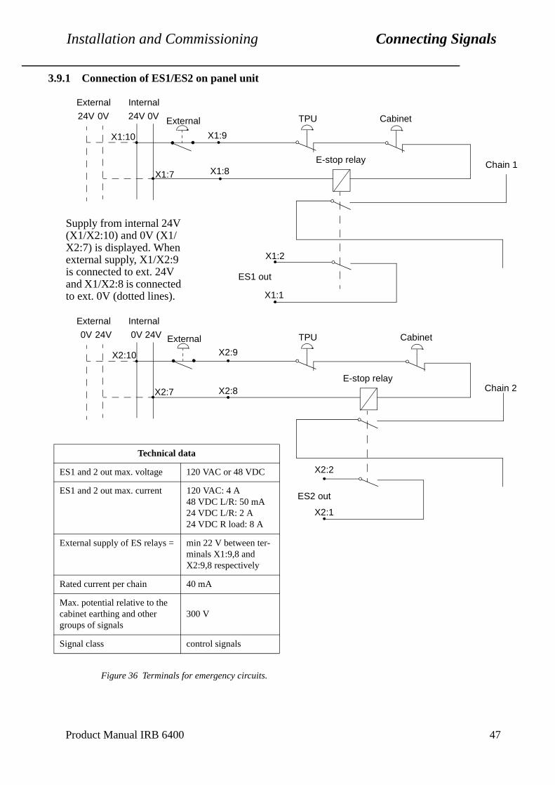
Installation and Commissioning Connecting Signals
3.9.1 Connection of ES1/ES2 on panel unit
Figure 36 Terminals for emergency circuits.
External Internal
24V 0V 24V 0V
X1:10
X1:7 X1:8
X1:9
TPU
E-stop relay
Cabinet
Chain 1
ES1 out
X1:2
X1:1
External Internal
0V 24V 0V 24V
X2:10
X2:7 X2:8
X2:9
TPU
E-stop relay
Cabinet
Chain 2
ES2 out
X2:2
X2:1
Technical data
ES1 and 2 out max. voltage 120 VAC or 48 VDC
ES1 and 2 out max. current 120 VAC: 4 A48 VDC L/R: 50 mA24 VDC L/R: 2 A24 VDC R load: 8 A
External supply of ES relays = min 22 V between ter-minals X1:9,8 and X2:9,8 respectively
Rated current per chain 40 mA
Max. potential relative to the cabinet earthing and other groups of signals
300 V
Signal class control signals
External
Supply from internal 24V (X1/X2:10) and 0V (X1/X2:7) is displayed. When external supply, X1/X2:9 is connected to ext. 24V and X1/X2:8 is connected to ext. 0V (dotted lines).
External
Product Manual IRB 6400 47
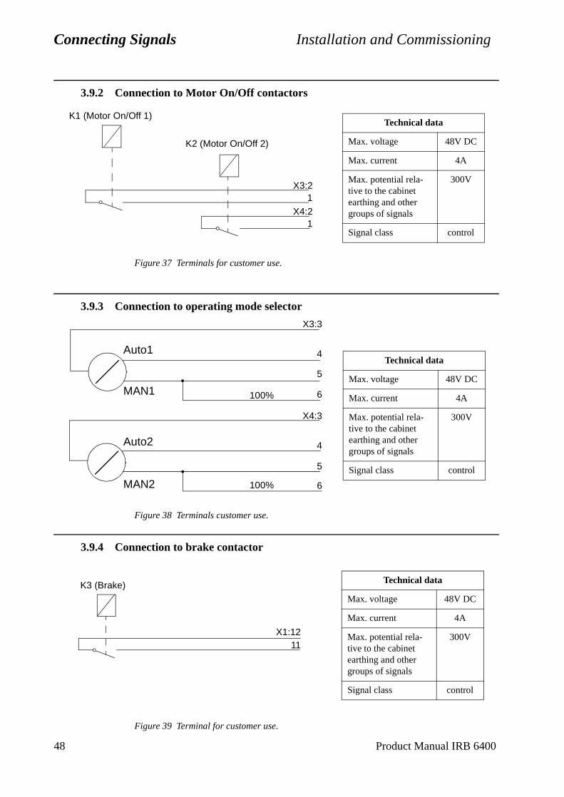
Connecting Signals Installation and Commissioning
48 Product Manual IRB 6400
3.9.2 Connection to Motor On/Off contactors
Figure 37 Terminals for customer use.
3.9.3 Connection to operating mode selector
Figure 38 Terminals customer use.
3.9.4 Connection to brake contactor
Figure 39 Terminal for customer use.
X3:2
X4:2
1
1
K2 (Motor On/Off 2)
K1 (Motor On/Off 1)Technical data
Max. voltage 48V DC
Max. current 4A
Max. potential rela-tive to the cabinet earthing and other groups of signals
300V
Signal class control
X3:3
X4:3
4
5
6
4
5
6100%
100%
MAN2
MAN1
Auto2
Auto1Technical data
Max. voltage 48V DC
Max. current 4A
Max. potential rela-tive to the cabinet earthing and other groups of signals
300V
Signal class control
X1:1211
K3 (Brake) Technical data
Max. voltage 48V DC
Max. current 4A
Max. potential rela-tive to the cabinet earthing and other groups of signals
300V
Signal class control
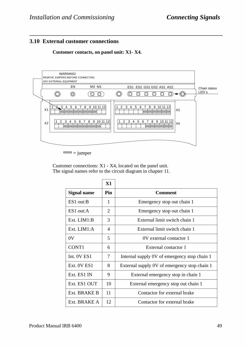
Installation and Commissioning Connecting Signals
Product Manual IRB 6400 49
3.10 External customer connections
Customer contacts, on panel unit: X1- X4.
Customer connections: X1 - X4, located on the panel unit.The signal names refer to the circuit diagram in chapter 11.
X1
Signal name Pin Comment
ES1 out:B 1 Emergency stop out chain 1
ES1 out:A 2 Emergency stop out chain 1
Ext. LIM1:B 3 External limit switch chain 1
Ext. LIM1:A 4 External limit switch chain 1
0V 5 0V external contactor 1
CONT1 6 External contactor 1
Int. 0V ES1 7 Internal supply 0V of emergency stop chain 1
Ext. 0V ES1 8 External supply 0V of emergency stop chain 1
Ext. ES1 IN 9 External emergency stop in chain 1
Ext. ES1 OUT 10 External emergency stop out chain 1
Ext. BRAKE B 11 Contactor for external brake
Ext. BRAKE A 12 Contactor for external brake
AS2AS1GS1ES2ES1 GS2NSMSEN
WARNING!REMOVE JUMPERS BEFORE CONNECTING
ANY EXTERNAL EQUIPMENT
X1
X2
X3
X4
Chain statusLED´s
1 2 4 53 6 7 8 9 10 1211
1 2 4 53 6 7 8 9 10 1211 1 2 4 53 6 7 8 9 10 1211
1 2 4 53 6 7 8 9 10 1211
= jumper
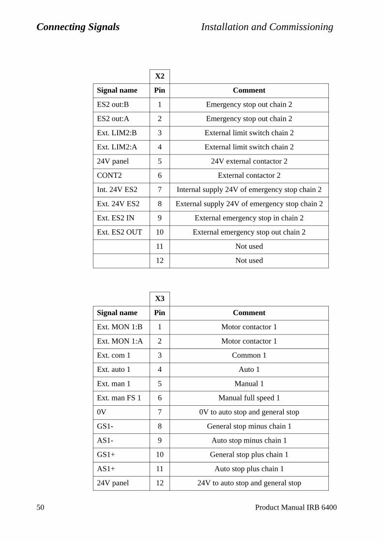
Connecting Signals Installation and Commissioning
X2
Signal name Pin Comment
ES2 out:B 1 Emergency stop out chain 2
ES2 out:A 2 Emergency stop out chain 2
Ext. LIM2:B 3 External limit switch chain 2
Ext. LIM2:A 4 External limit switch chain 2
24V panel 5 24V external contactor 2
CONT2 6 External contactor 2
Int. 24V ES2 7 Internal supply 24V of emergency stop chain 2
Ext. 24V ES2 8 External supply 24V of emergency stop chain 2
Ext. ES2 IN 9 External emergency stop in chain 2
Ext. ES2 OUT 10 External emergency stop out chain 2
11 Not used
12 Not used
X3
Signal name Pin Comment
Ext. MON 1:B 1 Motor contactor 1
Ext. MON 1:A 2 Motor contactor 1
Ext. com 1 3 Common 1
Ext. auto 1 4 Auto 1
Ext. man 1 5 Manual 1
Ext. man FS 1 6 Manual full speed 1
0V 7 0V to auto stop and general stop
GS1- 8 General stop minus chain 1
AS1- 9 Auto stop minus chain 1
GS1+ 10 General stop plus chain 1
AS1+ 11 Auto stop plus chain 1
24V panel 12 24V to auto stop and general stop
50 Product Manual IRB 6400
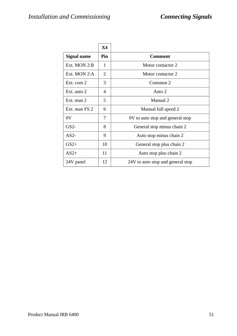
Installation and Commissioning Connecting Signals
X4
Signal name Pin Comment
Ext. MON 2:B 1 Motor contactor 2
Ext. MON 2:A 2 Motor contactor 2
Ext. com 2 3 Common 2
Ext. auto 2 4 Auto 2
Ext. man 2 5 Manual 2
Ext. man FS 2 6 Manual full speed 2
0V 7 0V to auto stop and general stop
GS2- 8 General stop minus chain 2
AS2- 9 Auto stop minus chain 2
GS2+ 10 General stop plus chain 2
AS2+ 11 Auto stop plus chain 2
24V panel 12 24V to auto stop and general stop
Product Manual IRB 6400 51
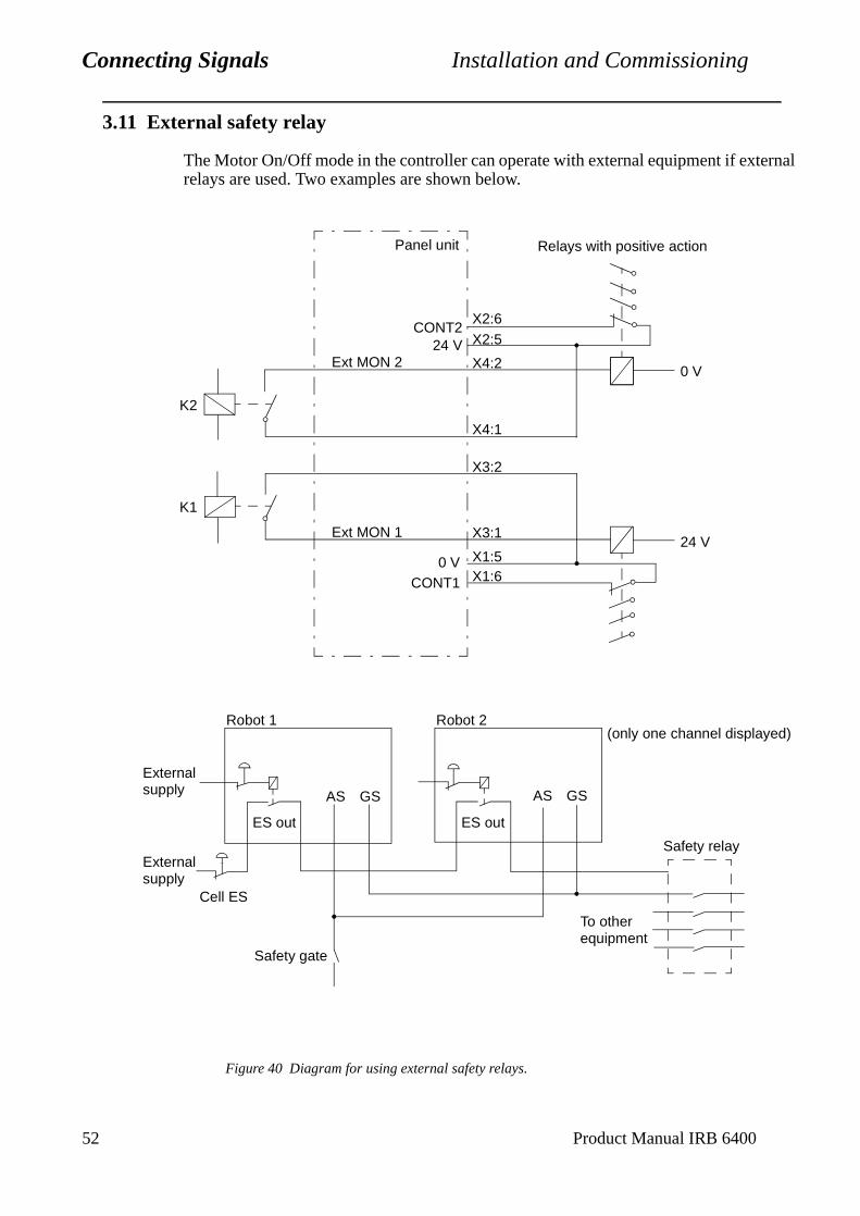
Connecting Signals Installation and Commissioning
5
2 Product Manual IRB 64003.11 External safety relay
The Motor On/Off mode in the controller can operate with external equipment if external relays are used. Two examples are shown below.
Figure 40 Diagram for using external safety relays.
K2
K1
X1:6X1:5
X3:1
X3:2
X4:1
X4:2
X2:5X2:6
0 VCONT1
Ext MON 1
Ext MON 224 V
CONT2
24 V
0 V
Panel unit Relays with positive action
Safety relay
To otherequipment
ES out
AS GSAS GS
ES out
Externalsupply
Externalsupply
Robot 1 Robot 2
Safety gate
Cell ES
(only one channel displayed)
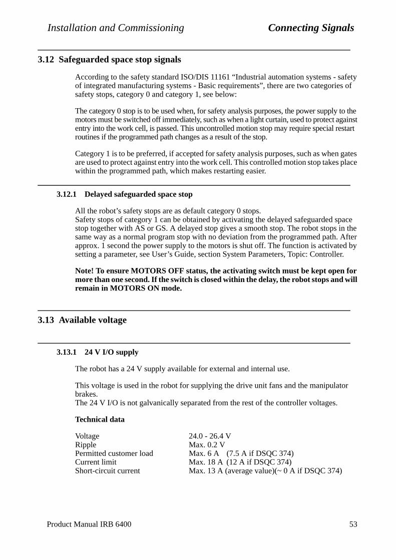
Installation and Commissioning Connecting Signals
afety s of
y to the gainst start
n gates place
space in the After ed by er.
or
3.12 Safeguarded space stop signals
According to the safety standard ISO/DIS 11161 “Industrial automation systems - sof integrated manufacturing systems - Basic requirements”, there are two categoriesafety stops, category 0 and category 1, see below:
The category 0 stop is to be used when, for safety analysis purposes, the power supplmotors must be switched off immediately, such as when a light curtain, used to protect aentry into the work cell, is passed. This uncontrolled motion stop may require special reroutines if the programmed path changes as a result of the stop.
Category 1 is to be preferred, if accepted for safety analysis purposes, such as wheare used to protect against entry into the work cell. This controlled motion stop takeswithin the programmed path, which makes restarting easier.
3.12.1 Delayed safeguarded space stop
All the robot’s safety stops are as default category 0 stops.Safety stops of category 1 can be obtained by activating the delayed safeguarded stop together with AS or GS. A delayed stop gives a smooth stop. The robot stops same way as a normal program stop with no deviation from the programmed path.approx. 1 second the power supply to the motors is shut off. The function is activatsetting a parameter, see User’s Guide, section System Parameters, Topic: Controll
Note! To ensure MOTORS OFF status, the activating switch must be kept open for more than one second. If the switch is closed within the delay, the robot stops and will remain in MOTORS ON mode.
3.13 Available voltage
3.13.1 24 V I/O supply
The robot has a 24 V supply available for external and internal use.
This voltage is used in the robot for supplying the drive unit fans and the manipulatbrakes.The 24 V I/O is not galvanically separated from the rest of the controller voltages.
Technical data
Voltage 24.0 - 26.4 VRipple Max. 0.2 VPermitted customer load Max. 6 A (7.5 A if DSQC 374)Current limit Max. 18 A (12 A if DSQC 374)Short-circuit current Max. 13 A (average value)(~ 0 A if DSQC 374)
Product Manual IRB 6400 53
Connecting Signals Installation and Commissioning
robot
nal
nt the mple, mmon
54 Product Manual IRB 6400
24 V I/O available for customer connections at:
XT.31.2 24 V (via 2 A fuse)XT.31.1 for own fuses, max. fuse size is 2 A to ensure breaking at short circuit
Note! DSQC 374 can not trip any fuses.XT.31.4 0 V (connected to cabinet structure)
3.13.2 115/230 V AC supply
The robot has a AC supply available for external and internal use.
This voltage is used in the robot for supplying optional service outlets.
The AC supply is not galvanically separated from the rest of the controller voltages.
Technical data
Voltage 115 or 230 VPermitted customer load Max. 500 VAFuse size 3.15 A (230 V), 6.3 A (115 V)
AC supply is available for customer connections at:
XT.21.1-5 230 V (3.15 A)XT.21.6-8 115 V (6.3 A)XT.21.9-13 N (connected to cabinet structure)
3.14 External 24 V supply
An external supply must be used in the following cases:
• When the internal supply is insufficient
• When the emergency stop circuits must be independent of whether or not thehas power on, for example.
• When there is a risk that major interference can be carried over into the inter 24 V supply
An external supply is recommended to make use of the advantages offered by the galvanic insulation on the I/O units or on the panel unit.
The neutral wire in the external supply must be connected in such a way as to prevemaximum permitted potential difference in the chassis earth being exceeded. For exaa neutral wire can be connected to the chassis earth of the controller, or some other coearthing point.
Technical data:
Potential difference to chassis earth: Max. 60 V continuousMax. 500 V for 1 minute
Permitted supply voltage: I/O units 19 - 35 V including ripplepanel unit 20.6 - 30 V including ripple
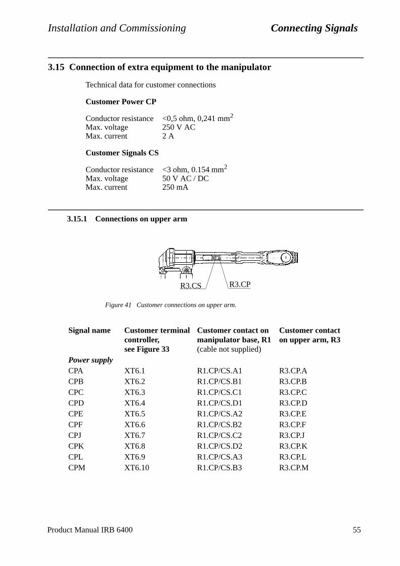
Installation and Commissioning Connecting Signals
3.15 Connection of extra equipment to the manipulator
Technical data for customer connections
Customer Power CP
Conductor resistance <0,5 ohm, 0,241 mm2
Max. voltage 250 V ACMax. current 2 A
Customer Signals CS
Conductor resistance <3 ohm, 0.154 mm2
Max. voltage 50 V AC / DCMax. current 250 mA
3.15.1 Connections on upper arm
Figure 41 Customer connections on upper arm.
Signal name Customer terminalcontroller, see Figure 33
Customer contact on manipulator base, R1(cable not supplied)
Customer contacton upper arm, R3
Power supplyCPA XT6.1 R1.CP/CS.A1 R3.CP.ACPB XT6.2 R1.CP/CS.B1 R3.CP.BCPC XT6.3 R1.CP/CS.C1 R3.CP.CCPD XT6.4 R1.CP/CS.D1 R3.CP.DCPE XT6.5 R1.CP/CS.A2 R3.CP.ECPF XT6.6 R1.CP/CS.B2 R3.CP.FCPJ XT6.7 R1.CP/CS.C2 R3.CP.JCPK XT6.8 R1.CP/CS.D2 R3.CP.KCPL XT6.9 R1.CP/CS.A3 R3.CP.LCPM XT6.10 R1.CP/CS.B3 R3.CP.M
R3.CS R3.CP
Product Manual IRB 6400 55
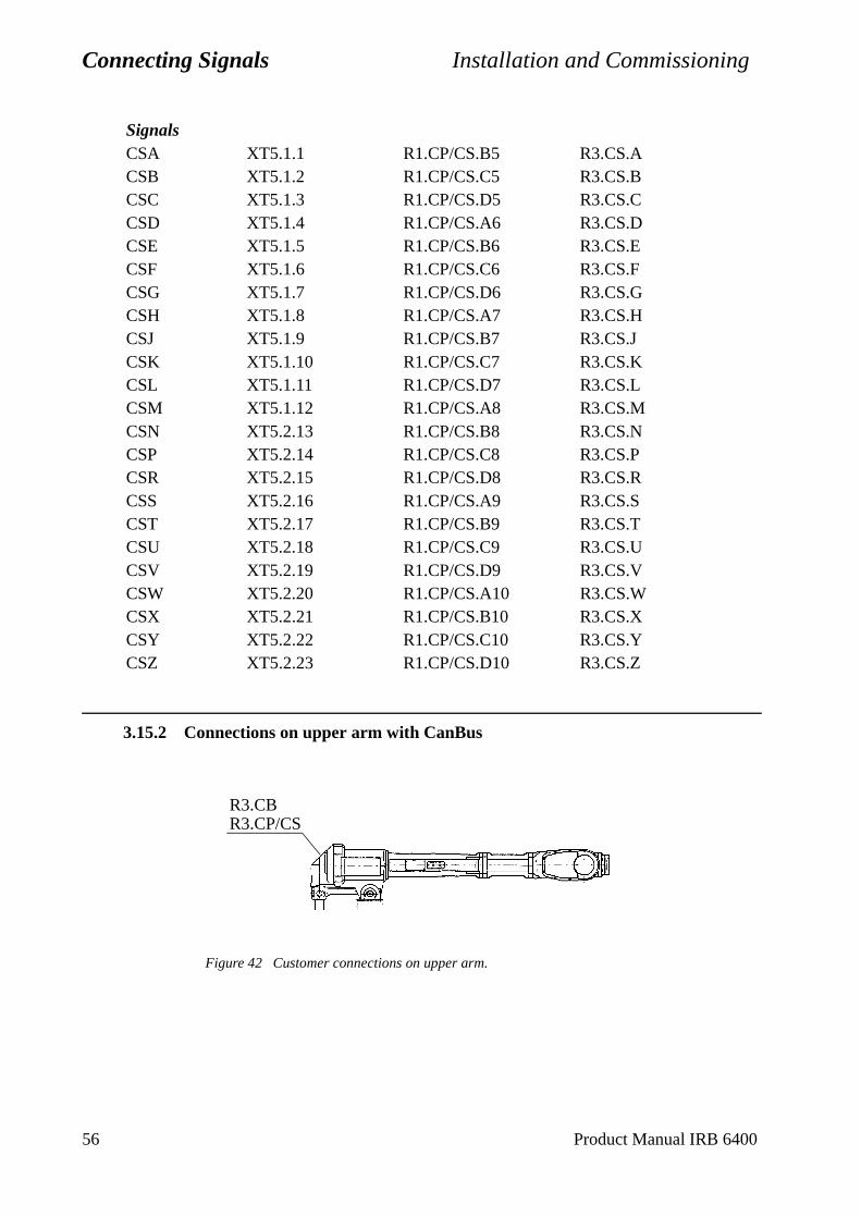
Connecting Signals Installation and Commissioning
3.15.2 Connections on upper arm with CanBus
Figure 42 Customer connections on upper arm.
SignalsCSA XT5.1.1 R1.CP/CS.B5 R3.CS.ACSB XT5.1.2 R1.CP/CS.C5 R3.CS.BCSC XT5.1.3 R1.CP/CS.D5 R3.CS.CCSD XT5.1.4 R1.CP/CS.A6 R3.CS.DCSE XT5.1.5 R1.CP/CS.B6 R3.CS.ECSF XT5.1.6 R1.CP/CS.C6 R3.CS.FCSG XT5.1.7 R1.CP/CS.D6 R3.CS.GCSH XT5.1.8 R1.CP/CS.A7 R3.CS.HCSJ XT5.1.9 R1.CP/CS.B7 R3.CS.JCSK XT5.1.10 R1.CP/CS.C7 R3.CS.KCSL XT5.1.11 R1.CP/CS.D7 R3.CS.LCSM XT5.1.12 R1.CP/CS.A8 R3.CS.MCSN XT5.2.13 R1.CP/CS.B8 R3.CS.NCSP XT5.2.14 R1.CP/CS.C8 R3.CS.PCSR XT5.2.15 R1.CP/CS.D8 R3.CS.RCSS XT5.2.16 R1.CP/CS.A9 R3.CS.SCST XT5.2.17 R1.CP/CS.B9 R3.CS.TCSU XT5.2.18 R1.CP/CS.C9 R3.CS.UCSV XT5.2.19 R1.CP/CS.D9 R3.CS.VCSW XT5.2.20 R1.CP/CS.A10 R3.CS.WCSX XT5.2.21 R1.CP/CS.B10 R3.CS.XCSY XT5.2.22 R1.CP/CS.C10 R3.CS.YCSZ XT5.2.23 R1.CP/CS.D10 R3.CS.Z
R3.CBR3.CP/CS
56 Product Manual IRB 6400

Installation and Commissioning Connecting Signals
Signal name Customer terminalcontroller, see Figure 33
Customer contact on manipulator base, R1(cable not supplied)
Customer contacton upper arm, R3
Power supplyCPF XT6.1 R1.CP/CS.1 R3.CP.FCPJ XT6.2 R1.CP/CS.2 R3.CP.JCPK XT6.3 R1.CP/CS.3 R3.CP.KCPL XT6.4 R1.CP/CS.4 R3.CP.LCPM XT6.5 R1.CP/CS.5 R3.CP.M
SignalsCSA XT5.1 R1.CP/CS.13 R3.CS.ACSB XT5.2 R1.CP/CS.14 R3.CS.BCSC XT5.3 R1.CP/CS.15 R3.CS.CCSD XT5.3 R1.CP/CS.16 R3.CS.DCSE XT5.5 R1.CP/CS.17 R3.CS.ECSF XT5.6 R1.CP/CS.18 R3.CS.FCSG XT5.7 R1.CP/CS.19 R3.CS.GCSH XT5.8 R1.CP/CS.20 R3.CS.HCSJ XT5.9 R1.CP/CS.21 R3.CS.JCSK XT5.10 R1.CP/CS.22 R3.CS.KCSL XT5.11 R1.CP/CS.23 R3.CS.LCSM XT5.12 R1.CP/CS.24 R3.CS.M
CanBusDRAIN R1.CB.1 R3.CB.1+24VCAN R1.CB.2 R3.CB.20VCAN R1.CB.3 R3.CB.3CAN_H R1.CB.4 R3.CB.4CAN_L R1.CB.5 R3.CB.5
Product Manual IRB 6400 57
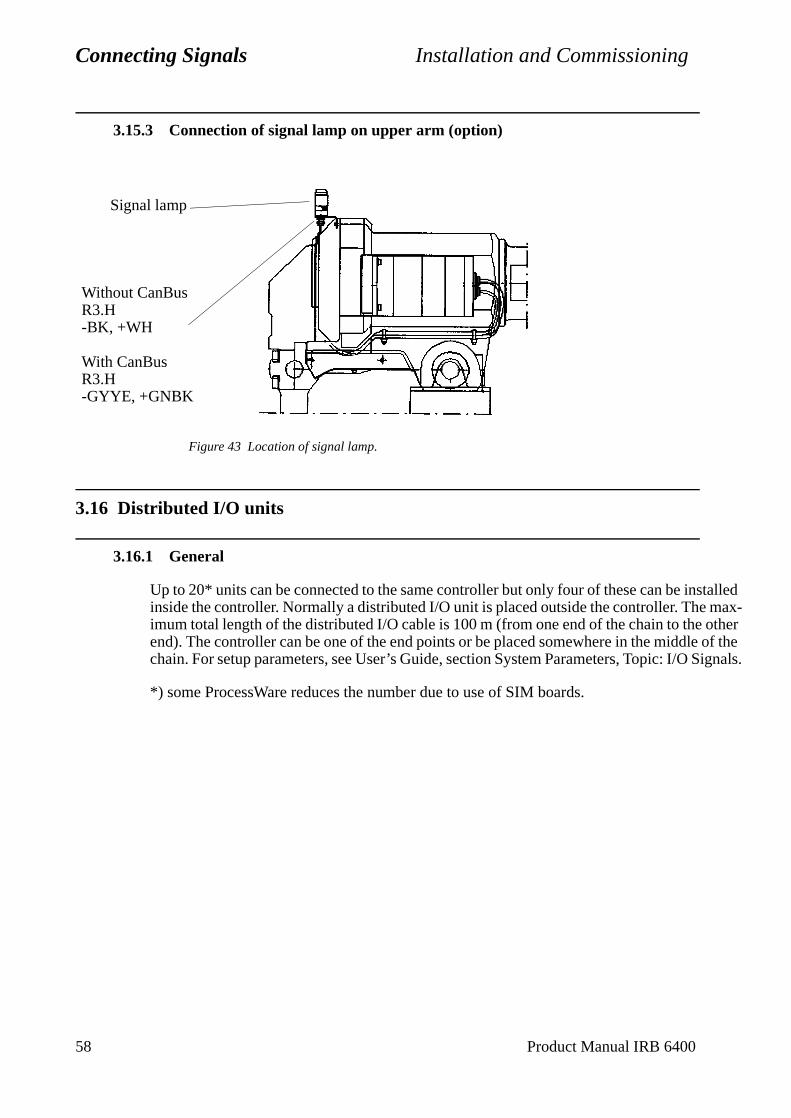
Connecting Signals Installation and Commissioning
Signals.
58 Product Manual IRB 6400
3.15.3 Connection of signal lamp on upper arm (option)
Figure 43 Location of signal lamp.
3.16 Distributed I/O units
3.16.1 General
Up to 20* units can be connected to the same controller but only four of these can be installed inside the controller. Normally a distributed I/O unit is placed outside the controller. The max-imum total length of the distributed I/O cable is 100 m (from one end of the chain to the other end). The controller can be one of the end points or be placed somewhere in the middle of the chain. For setup parameters, see User’s Guide, section System Parameters, Topic: I/O
*) some ProcessWare reduces the number due to use of SIM boards.
Signal lamp
Without CanBusR3.H-BK, +WH
With CanBusR3.H-GYYE, +GNBK
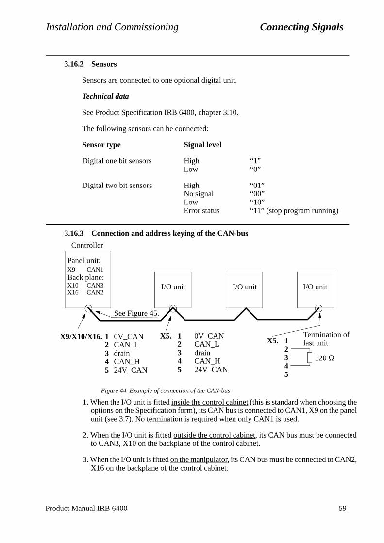
Installation and Commissioning Connecting Signals
e anel
,
3.16.2 Sensors
Sensors are connected to one optional digital unit.
Technical data
See Product Specification IRB 6400, chapter 3.10.
The following sensors can be connected:
Sensor type Signal level
Digital one bit sensors High “1”Low “0”
Digital two bit sensors High “01”No signal “00”Low “10”Error status “11” (stop program running)
3.16.3 Connection and address keying of the CAN-bus
Figure 44 Example of connection of the CAN-bus
1. When the I/O unit is fitted inside the control cabinet (this is standard when choosing thoptions on the Specification form), its CAN bus is connected to CAN1, X9 on the punit (see 3.7). No termination is required when only CAN1 is used.
2. When the I/O unit is fitted outside the control cabinet, its CAN bus must be connectedto CAN3, X10 on the backplane of the control cabinet.
3. When the I/O unit is fitted on the manipulator, its CAN bus must be connected to CAN2X16 on the backplane of the control cabinet.
Panel unit:X9 CAN1Back plane:X10 CAN3X16 CAN2
Controller
X9/X10/X16. 1 0V_CAN2 CAN_L3 drain4 CAN_H5 24V_CAN
I/O unit I/O unit I/O unit
X5. 1 0V_CAN2 CAN_L3 drain4 CAN_H5 24V_CAN
X5. 12345
120 Ω
Termination of last unit
See Figure 45.
Product Manual IRB 6400 59
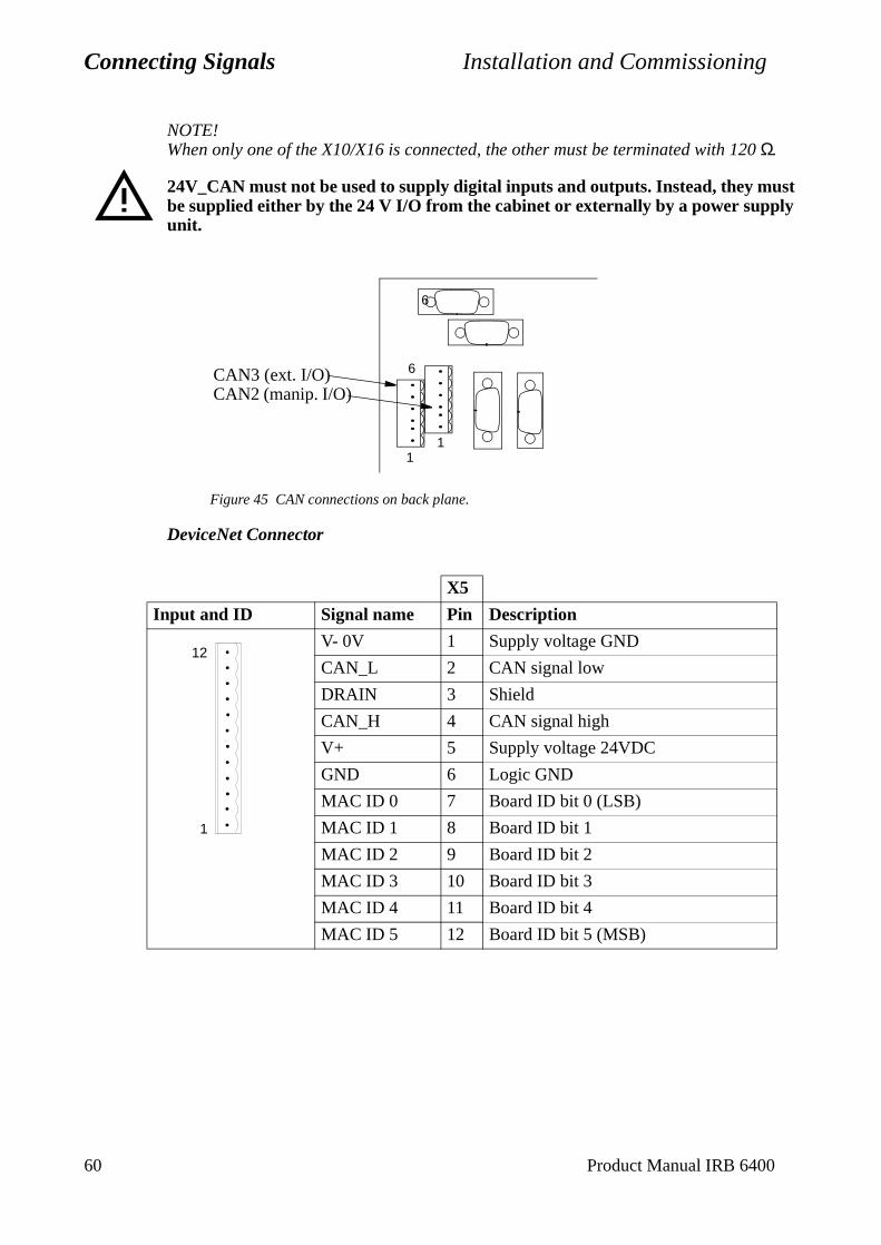
Connecting Signals Installation and Commissioning
NOTE!When only one of the X10/X16 is connected, the other must be terminated with 120 Ω.
24V_CAN must not be used to supply digital inputs and outputs. Instead, they must be supplied either by the 24 V I/O from the cabinet or externally by a power supply unit.
Figure 45 CAN connections on back plane.
DeviceNet Connector
X5
Input and ID Signal name Pin Description
V- 0V 1 Supply voltage GND
CAN_L 2 CAN signal low
DRAIN 3 Shield
CAN_H 4 CAN signal high
V+ 5 Supply voltage 24VDC
GND 6 Logic GND
MAC ID 0 7 Board ID bit 0 (LSB)
MAC ID 1 8 Board ID bit 1
MAC ID 2 9 Board ID bit 2
MAC ID 3 10 Board ID bit 3
MAC ID 4 11 Board ID bit 4
MAC ID 5 12 Board ID bit 5 (MSB)
CAN3 (ext. I/O)CAN2 (manip. I/O)
11
6
6
1
12
60 Product Manual IRB 6400
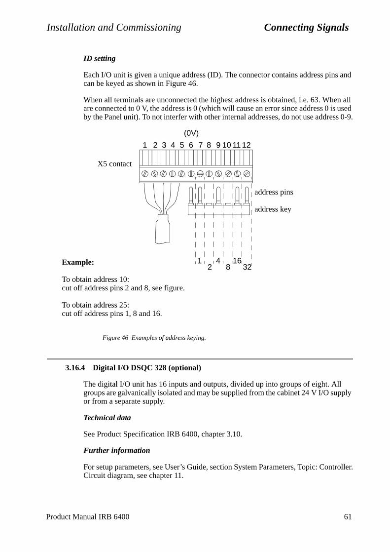
Installation and Commissioning Connecting Signals
troller.
ID setting
Each I/O unit is given a unique address (ID). The connector contains address pins and can be keyed as shown in Figure 46.
When all terminals are unconnected the highest address is obtained, i.e. 63. When all are connected to 0 V, the address is 0 (which will cause an error since address 0 is used by the Panel unit). To not interfer with other internal addresses, do not use address 0-9.
Figure 46 Examples of address keying.
3.16.4 Digital I/O DSQC 328 (optional)
The digital I/O unit has 16 inputs and outputs, divided up into groups of eight. All groups are galvanically isolated and may be supplied from the cabinet 24 V I/O supply or from a separate supply.
Technical data
See Product Specification IRB 6400, chapter 3.10.
Further information
For setup parameters, see User’s Guide, section System Parameters, Topic: ConCircuit diagram, see chapter 11.
X5 contact
6 8 9 10 11 127
(0V)
address pins
address key
1 48
16322
Example:
To obtain address 10: cut off address pins 2 and 8, see figure.
To obtain address 25:cut off address pins 1, 8 and 16.
1 2 3 4 5
Product Manual IRB 6400 61
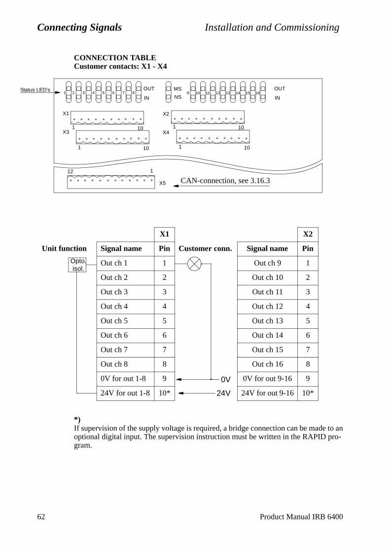
Connecting Signals Installation and Commissioning
Statu
CONNECTION TABLE Customer contacts: X1 - X4
*)If supervision of the supply voltage is required, a bridge connection can be made to an optional digital input. The supervision instruction must be written in the RAPID pro-gram.
OUT
INNS
MS16151413121110987654321
OUT
IN
X1
X3
X2
X4
101101
101 101
s LED’s
X5
112
CAN-connection, see 3.16.3
X1 X2
Unit function Signal name Pin Customer conn. Signal name Pin
Out ch 1 1 Out ch 9 1
Out ch 2 2 Out ch 10 2
Out ch 3 3 Out ch 11 3
Out ch 4 4 Out ch 12 4
Out ch 5 5 Out ch 13 5
Out ch 6 6 Out ch 14 6
Out ch 7 7 Out ch 15 7
Out ch 8 8 Out ch 16 8
0V for out 1-8 9 0V for out 9-16 9
24V for out 1-8 10* 24V for out 9-16 10*
Opto.isol.
24V
0V
62 Product Manual IRB 6400
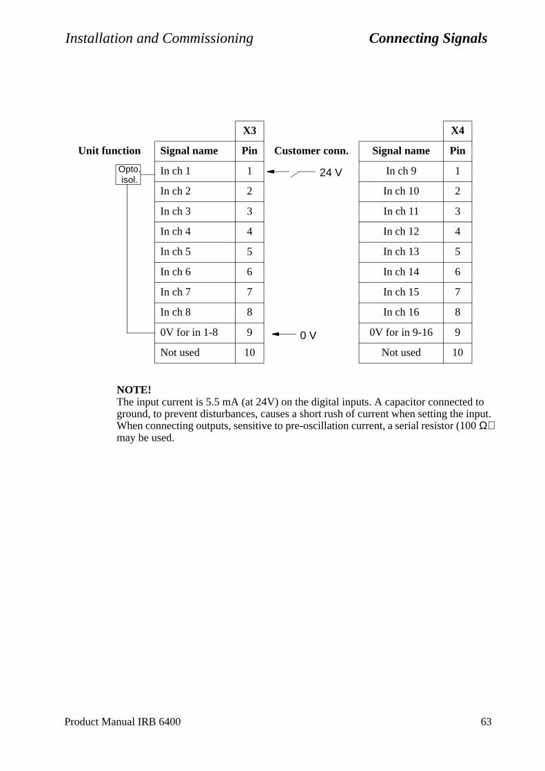
Installation and Commissioning Connecting Signals
NOTE!The input current is 5.5 mA (at 24V) on the digital inputs. A capacitor connected to ground, to prevent disturbances, causes a short rush of current when setting the input. When connecting outputs, sensitive to pre-oscillation current, a serial resistor (100 Ω) may be used.
X3 X4
Unit function Signal name Pin Customer conn. Signal name Pin
In ch 1 1 In ch 9 1
In ch 2 2 In ch 10 2
In ch 3 3 In ch 11 3
In ch 4 4 In ch 12 4
In ch 5 5 In ch 13 5
In ch 6 6 In ch 14 6
In ch 7 7 In ch 15 7
In ch 8 8 In ch 16 8
0V for in 1-8 9 0V for in 9-16 9
Not used 10 Not used 10
Opto.isol.
0 V
24 V
Product Manual IRB 6400 63
Connecting Signals Installation and Commissioning
ntroller.
3.16.5 AD Combi I/O DSQC 327 (optional)
The combi I/O unit has 16 digital inputs divided into groups of 8, and 16 digital outputs divided into two groups of 8. All groups are galvanically isolated and may be supplied from the cabinet 24 V I/O supply or from a separate supply.
The two analog outputs belong to a common group which is galvanically isolated from the electronics of the controller. The supply to the two analog outputs is generated from 24 V_CAN (with galvanically isolated DC/AC converter).
Technical data
See Product Specification IRB 6400, chapter 3.10.
Further information
For setup parameters, see User’s Guide, section System Parameters, Topic: CoCircuit diagram, see chapter 11.
64 Product Manual IRB 6400
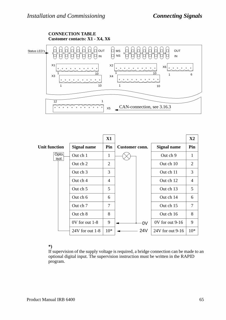
Installation and Commissioning Connecting Signals
CONNECTION TABLECustomer contacts: X1 - X4, X6
*)If supervision of the supply voltage is required, a bridge connection can be made to an optional digital input. The supervision instruction must be written in the RAPID program.
OUT
INNS
MS16151413121110987654321
OUT
IN
X1
X3
X2
X4
X6
1 10 101
1 6101 101
Status LED’s
X5
112
CAN-connection, see 3.16.3
X1 X2
Unit function Signal name Pin Customer conn. Signal name Pin
Out ch 1 1 Out ch 9 1
Out ch 2 2 Out ch 10 2
Out ch 3 3 Out ch 11 3
Out ch 4 4 Out ch 12 4
Out ch 5 5 Out ch 13 5
Out ch 6 6 Out ch 14 6
Out ch 7 7 Out ch 15 7
Out ch 8 8 Out ch 16 8
0V for out 1-8 9 0V for out 9-16 9
24V for out 1-8 10* 24V for out 9-16 10*
Opto.isol.
24V
0V
Product Manual IRB 6400 65

Connecting Signals Installation and Commissioning
NOTE!The input current is 5.5 mA (at 24V) on the digital inputs. A capacitor connected to ground, to prevent disturbances, causes a short rush of current when setting the input. When connecting outputs, sensitive to pre-oscillation current, a serial resistor (100 Ω) may be used.
X6
Signal name Pin Explanation
AN_ICH1 1 For test purpose only
AN_ICH2 2 For test purpose only
0V 3 0V for In 1-2
0VA 4 0V for Out 1-2
AN_OCH1 5 Out ch 1
AN_OCH2 6 Out ch 2
X3 X4
Unit function Signal name Pin Customer conn. Signal name Pin
In ch 1 1 In ch 9 1
In ch 2 2 In ch 10 2
In ch 3 3 In ch 11 3
In ch 4 4 In ch 12 4
In ch 5 5 In ch 13 5
In ch 6 6 In ch 14 6
In ch 7 7 In ch 15 7
In ch 8 8 In ch 16 8
0V for in 1-8 9 0V for in 9-16 9
Not used 10 Not used 10
Opto.isol.
0 V
24 V
66 Product Manual IRB 6400
Installation and Commissioning Connecting Signals
troller.
3.16.6 Analog I/O DSQC 355 (optional)
The analog I/O unit provides following connections:
4 analog inputs, -10/+10V, which may be used for analog sensors etc.
4 analog outputs, 3 for -10/+10V and 1 for 4-20mA, for control of analog functions such as controlling glueing equipment etc.
24V to supply external equipment wich return signals to DSQC 355.
Technical data
See Product Specification IRB 6400, chapter 3.10.
Further information
For setup parameters, see User’s Guide, section System Parameters, Topic: ConCircuit diagram, see chapter 11.
Product Manual IRB 6400 67
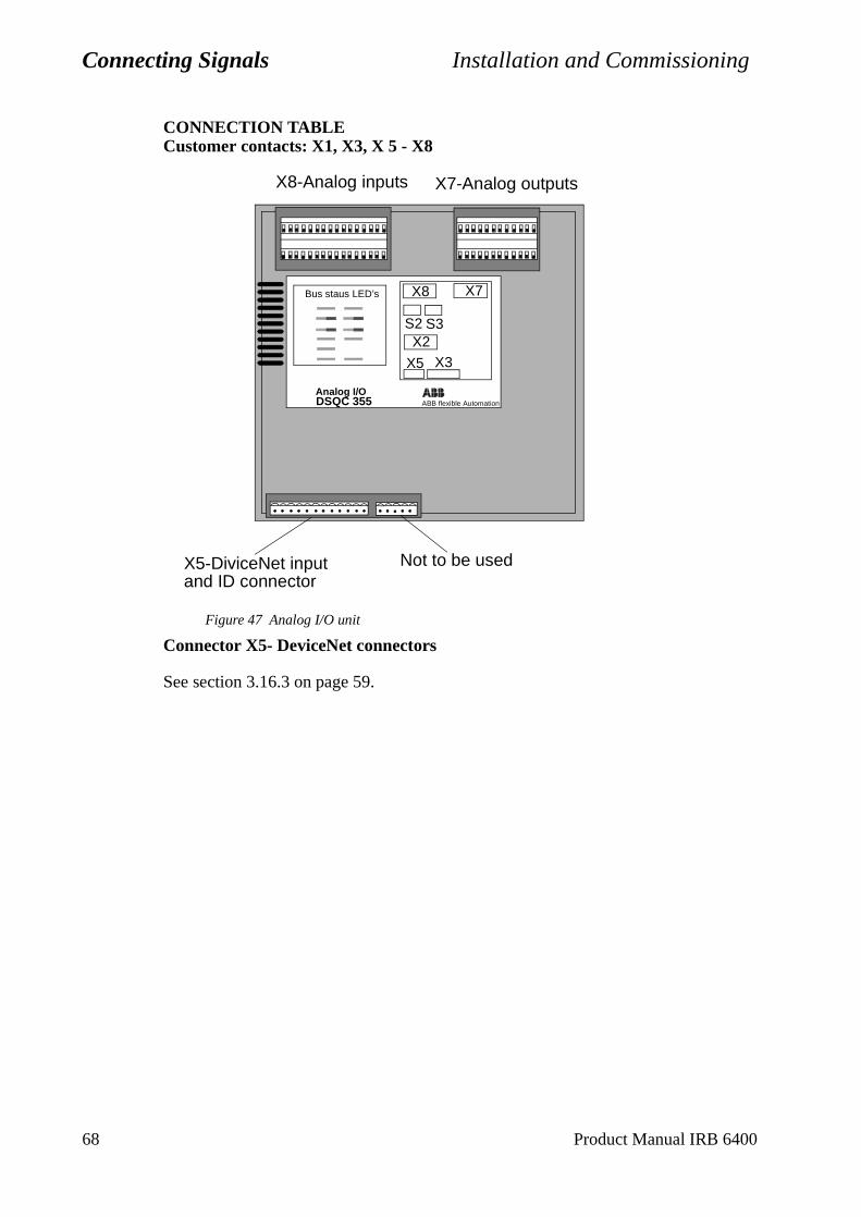
Connecting Signals Installation and Commissioning
CONNECTION TABLECustomer contacts: X1, X3, X 5 - X8
Figure 47 Analog I/O unit
Connector X5- DeviceNet connectors
See section 3.16.3 on page 59.
DSQC 355 ABB flexible Automation
Bus staus LED’s
Analog I/O
X8
S3S2
X3X5
X2
X7
X8-Analog inputs X7-Analog outputs
X5-DiviceNet inputand ID connector
Not to be used
68 Product Manual IRB 6400
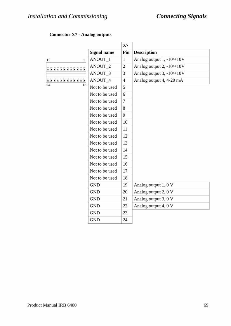
Installation and Commissioning Connecting Signals
Connector X7 - Analog outputs
X7
Signal name Pin Description
ANOUT_1 1 Analog output 1, -10/+10V
ANOUT_2 2 Analog output 2, -10/+10V
ANOUT_3 3 Analog output 3, -10/+10V
ANOUT_4 4 Analog output 4, 4-20 mA
Not to be used 5
Not to be used 6
Not to be used 7
Not to be used 8
Not to be used 9
Not to be used 10
Not to be used 11
Not to be used 12
Not to be used 13
Not to be used 14
Not to be used 15
Not to be used 16
Not to be used 17
Not to be used 18
GND 19 Analog output 1, 0 V
GND 20 Analog output 2, 0 V
GND 21 Analog output 3, 0 V
GND 22 Analog output 4, 0 V
GND 23
GND 24
112
1324
Product Manual IRB 6400 69
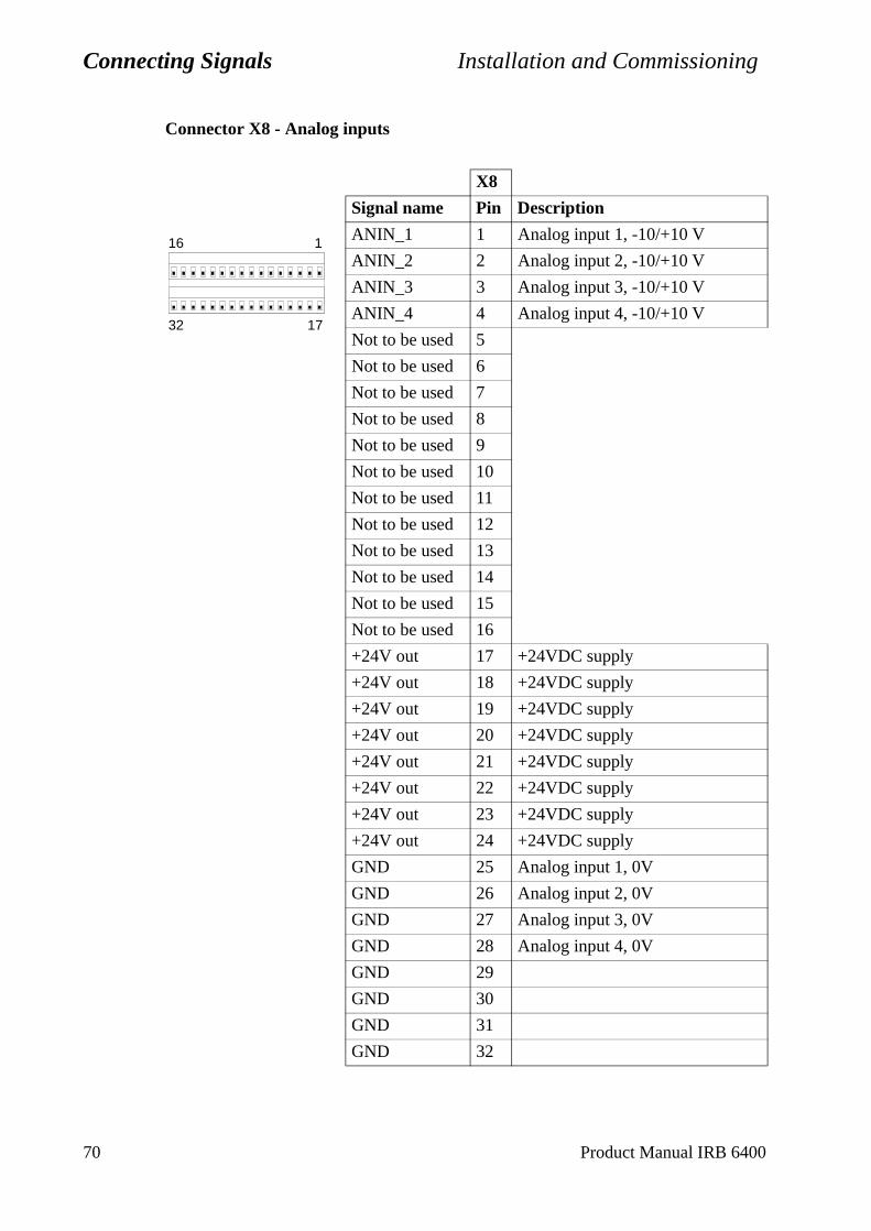
Connecting Signals Installation and Commissioning
Connector X8 - Analog inputs
X8
Signal name Pin Description
ANIN_1 1 Analog input 1, -10/+10 V
ANIN_2 2 Analog input 2, -10/+10 V
ANIN_3 3 Analog input 3, -10/+10 V
ANIN_4 4 Analog input 4, -10/+10 V
Not to be used 5
Not to be used 6
Not to be used 7
Not to be used 8
Not to be used 9
Not to be used 10
Not to be used 11
Not to be used 12
Not to be used 13
Not to be used 14
Not to be used 15
Not to be used 16
+24V out 17 +24VDC supply
+24V out 18 +24VDC supply
+24V out 19 +24VDC supply
+24V out 20 +24VDC supply
+24V out 21 +24VDC supply
+24V out 22 +24VDC supply
+24V out 23 +24VDC supply
+24V out 24 +24VDC supply
GND 25 Analog input 1, 0V
GND 26 Analog input 2, 0V
GND 27 Analog input 3, 0V
GND 28 Analog input 4, 0V
GND 29
GND 30
GND 31
GND 32
116
1732
70 Product Manual IRB 6400
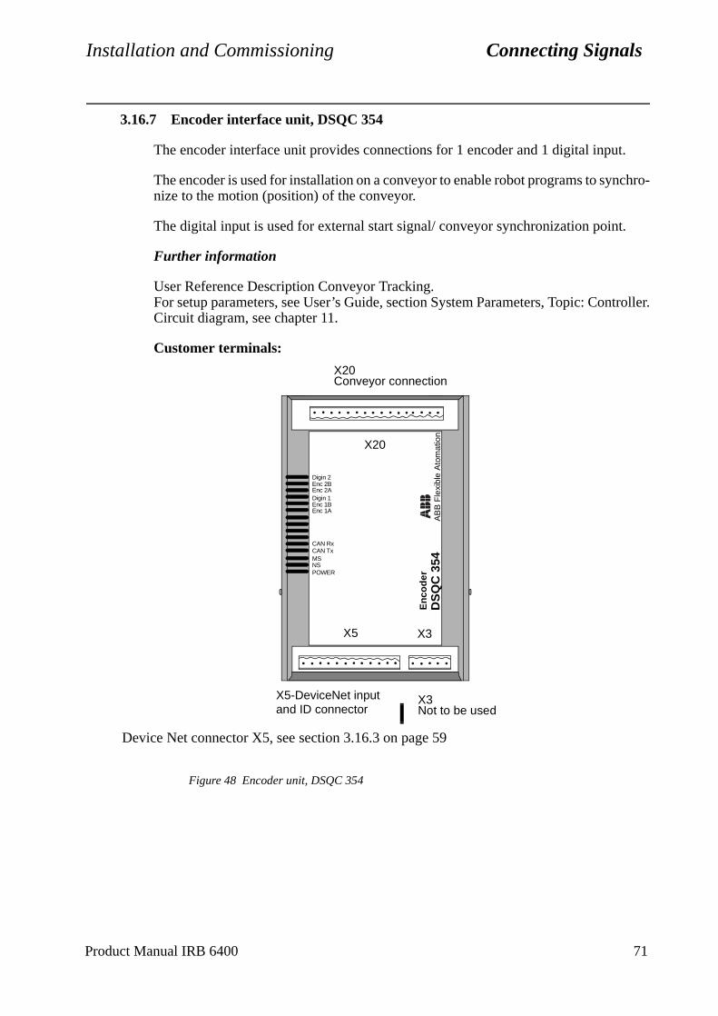
Installation and Commissioning Connecting Signals
troller.
3.16.7 Encoder interface unit, DSQC 354
The encoder interface unit provides connections for 1 encoder and 1 digital input.
The encoder is used for installation on a conveyor to enable robot programs to synchro-nize to the motion (position) of the conveyor.
The digital input is used for external start signal/ conveyor synchronization point.
Further information
User Reference Description Conveyor Tracking.For setup parameters, see User’s Guide, section System Parameters, Topic: ConCircuit diagram, see chapter 11.
Customer terminals:
Figure 48 Encoder unit, DSQC 354
Device Net connector X5, see section 3.16.3 on page 59
X5-DeviceNet input X3Not to be usedand ID connector
X20Conveyor connection
DS
QC
354
AB
B F
lexi
ble
Ato
mat
ion
X20
X5 X3
En
cod
er
Digin 1
CAN TxMSNSPOWER
CAN Rx
Enc 2AEnc 2BDigin 2
Enc 1AEnc 1B
Product Manual IRB 6400 71

Connecting Signals Installation and Commissioning
Figure 49 Encoder connections.
The wiring diagram in Figure 49 shows how to connect the encoder and start signal switch to the encoder unit. As can be seen from the illustration, the encoder is supplied with 24 VDC and 0V. The encoder output 2 channels, and the on-board computer uses quadrature decoding (QDEC) to compute position and direction.
Encoder unit
123456789
10111213141516
Opto
Opto
Opto
Opto
Opto
Opto
Galvanicinsulation
24 V I/O
0 V
Encoder
B
A
24 V DC
0 V
24 V DC
0 VSynch switch
10-16 not to be used
or external supply
72 Product Manual IRB 6400
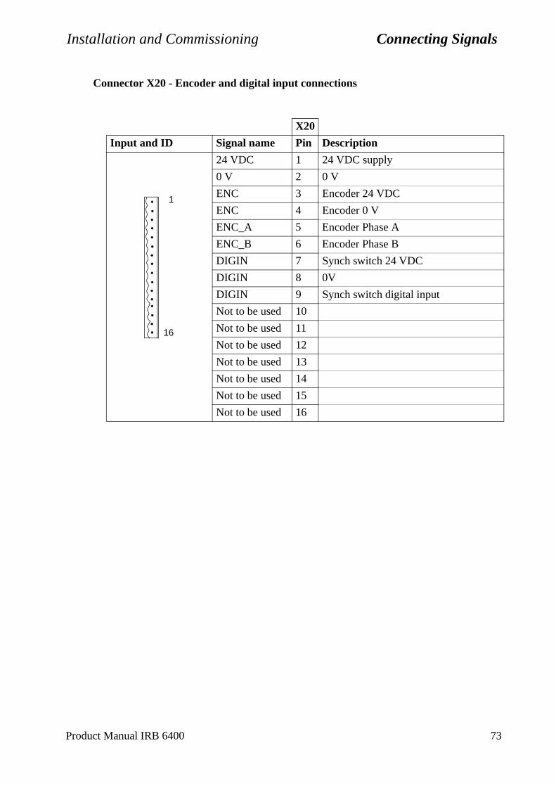
Installation and Commissioning Connecting Signals
Connector X20 - Encoder and digital input connections
X20
Input and ID Signal name Pin Description
24 VDC 1 24 VDC supply
0 V 2 0 V
ENC 3 Encoder 24 VDC
ENC 4 Encoder 0 V
ENC_A 5 Encoder Phase A
ENC_B 6 Encoder Phase B
DIGIN 7 Synch switch 24 VDC
DIGIN 8 0V
DIGIN 9 Synch switch digital input
Not to be used 10
Not to be used 11
Not to be used 12
Not to be used 13
Not to be used 14
Not to be used 15
Not to be used 16
1
16
Product Manual IRB 6400 73
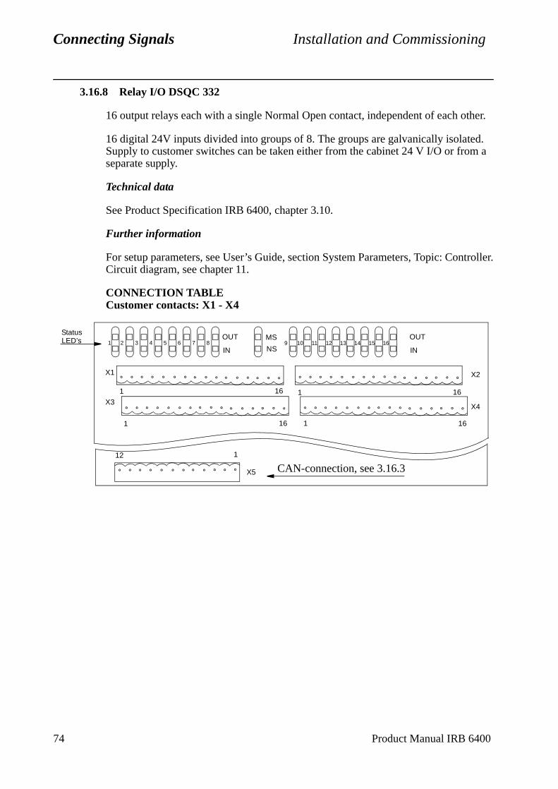
Connecting Signals Installation and Commissioning
ntroller.
74 Product Manual IRB 6400
3.16.8 Relay I/O DSQC 332
16 output relays each with a single Normal Open contact, independent of each other.
16 digital 24V inputs divided into groups of 8. The groups are galvanically isolated. Supply to customer switches can be taken either from the cabinet 24 V I/O or from a separate supply.
Technical data
See Product Specification IRB 6400, chapter 3.10.
Further information
For setup parameters, see User’s Guide, section System Parameters, Topic: CoCircuit diagram, see chapter 11.
CONNECTION TABLECustomer contacts: X1 - X4
OUT
INNS
MS16151413121110987654321
OUT
IN
X1
X3
161
X2
X4
161
161 161
Status LED’s
X5
112
CAN-connection, see 3.16.3
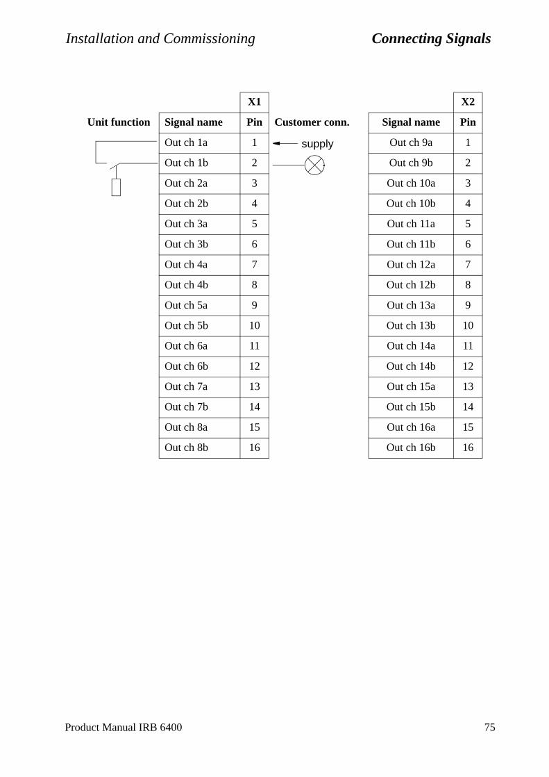
Installation and Commissioning Connecting Signals
X1 X2
Unit function Signal name Pin Customer conn. Signal name Pin
Out ch 1a 1 Out ch 9a 1
Out ch 1b 2 Out ch 9b 2
Out ch 2a 3 Out ch 10a 3
Out ch 2b 4 Out ch 10b 4
Out ch 3a 5 Out ch 11a 5
Out ch 3b 6 Out ch 11b 6
Out ch 4a 7 Out ch 12a 7
Out ch 4b 8 Out ch 12b 8
Out ch 5a 9 Out ch 13a 9
Out ch 5b 10 Out ch 13b 10
Out ch 6a 11 Out ch 14a 11
Out ch 6b 12 Out ch 14b 12
Out ch 7a 13 Out ch 15a 13
Out ch 7b 14 Out ch 15b 14
Out ch 8a 15 Out ch 16a 15
Out ch 8b 16 Out ch 16b 16
supply
Product Manual IRB 6400 75
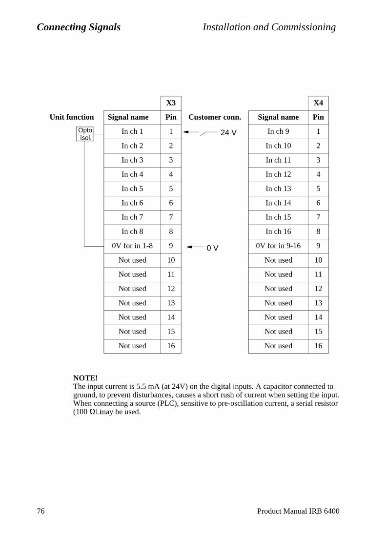
Connecting Signals Installation and Commissioning
NOTE!The input current is 5.5 mA (at 24V) on the digital inputs. A capacitor connected to ground, to prevent disturbances, causes a short rush of current when setting the input. When connecting a source (PLC), sensitive to pre-oscillation current, a serial resistor (100 Ω) may be used.
X3 X4
Unit function Signal name Pin Customer conn. Signal name Pin
In ch 1 1 In ch 9 1
In ch 2 2 In ch 10 2
In ch 3 3 In ch 11 3
In ch 4 4 In ch 12 4
In ch 5 5 In ch 13 5
In ch 6 6 In ch 14 6
In ch 7 7 In ch 15 7
In ch 8 8 In ch 16 8
0V for in 1-8 9 0V for in 9-16 9
Not used 10 Not used 10
Not used 11 Not used 11
Not used 12 Not used 12
Not used 13 Not used 13
Not used 14 Not used 14
Not used 15 Not used 15
Not used 16 Not used 16
Opto.isol.
0 V
24 V
76 Product Manual IRB 6400
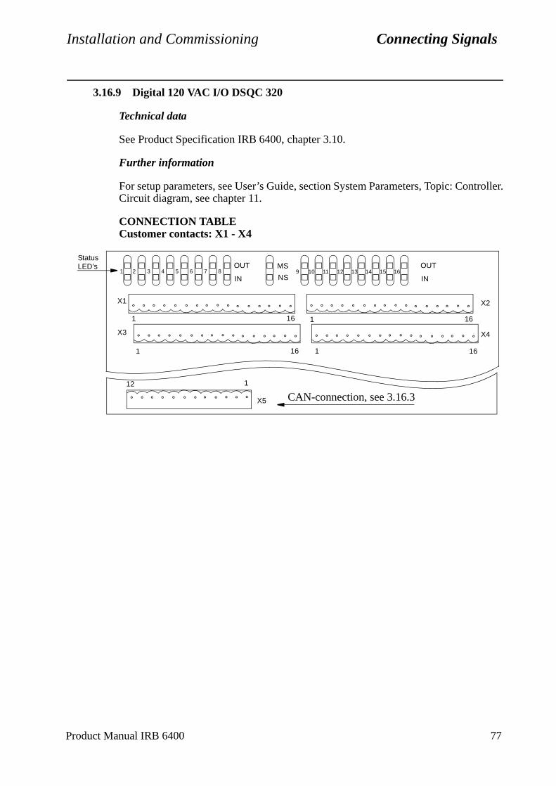
Installation and Commissioning Connecting Signals
troller.
3.16.9 Digital 120 VAC I/O DSQC 320
Technical data
See Product Specification IRB 6400, chapter 3.10.
Further information
For setup parameters, see User’s Guide, section System Parameters, Topic: ConCircuit diagram, see chapter 11.
CONNECTION TABLECustomer contacts: X1 - X4
OUT
INNS
MS16151413121110987654321
OUT
IN
X1
X3
161
X2
X4
161
161 161
StatusLED’s
X5
112
CAN-connection, see 3.16.3
Product Manual IRB 6400 77
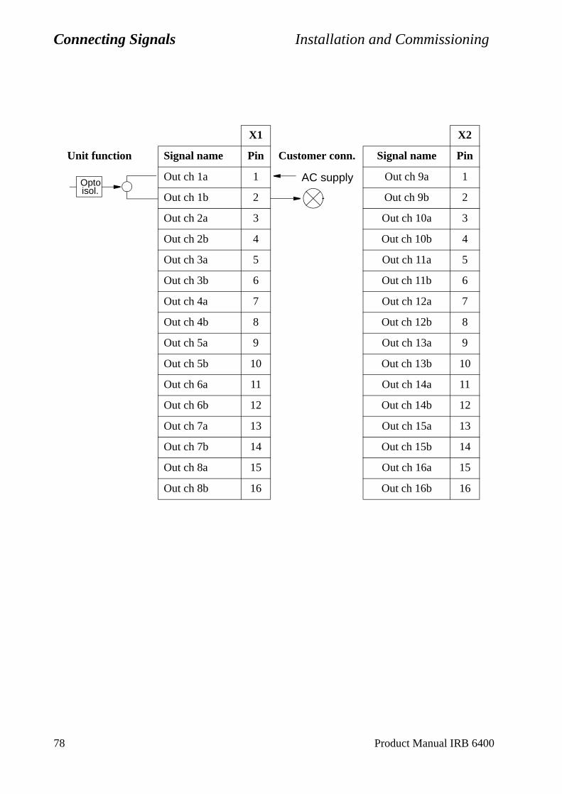
Connecting Signals Installation and Commissioning
X1 X2
Unit function Signal name Pin Customer conn. Signal name Pin
Out ch 1a 1 Out ch 9a 1
Out ch 1b 2 Out ch 9b 2
Out ch 2a 3 Out ch 10a 3
Out ch 2b 4 Out ch 10b 4
Out ch 3a 5 Out ch 11a 5
Out ch 3b 6 Out ch 11b 6
Out ch 4a 7 Out ch 12a 7
Out ch 4b 8 Out ch 12b 8
Out ch 5a 9 Out ch 13a 9
Out ch 5b 10 Out ch 13b 10
Out ch 6a 11 Out ch 14a 11
Out ch 6b 12 Out ch 14b 12
Out ch 7a 13 Out ch 15a 13
Out ch 7b 14 Out ch 15b 14
Out ch 8a 15 Out ch 16a 15
Out ch 8b 16 Out ch 16b 16
isol.Opto AC supply
78 Product Manual IRB 6400
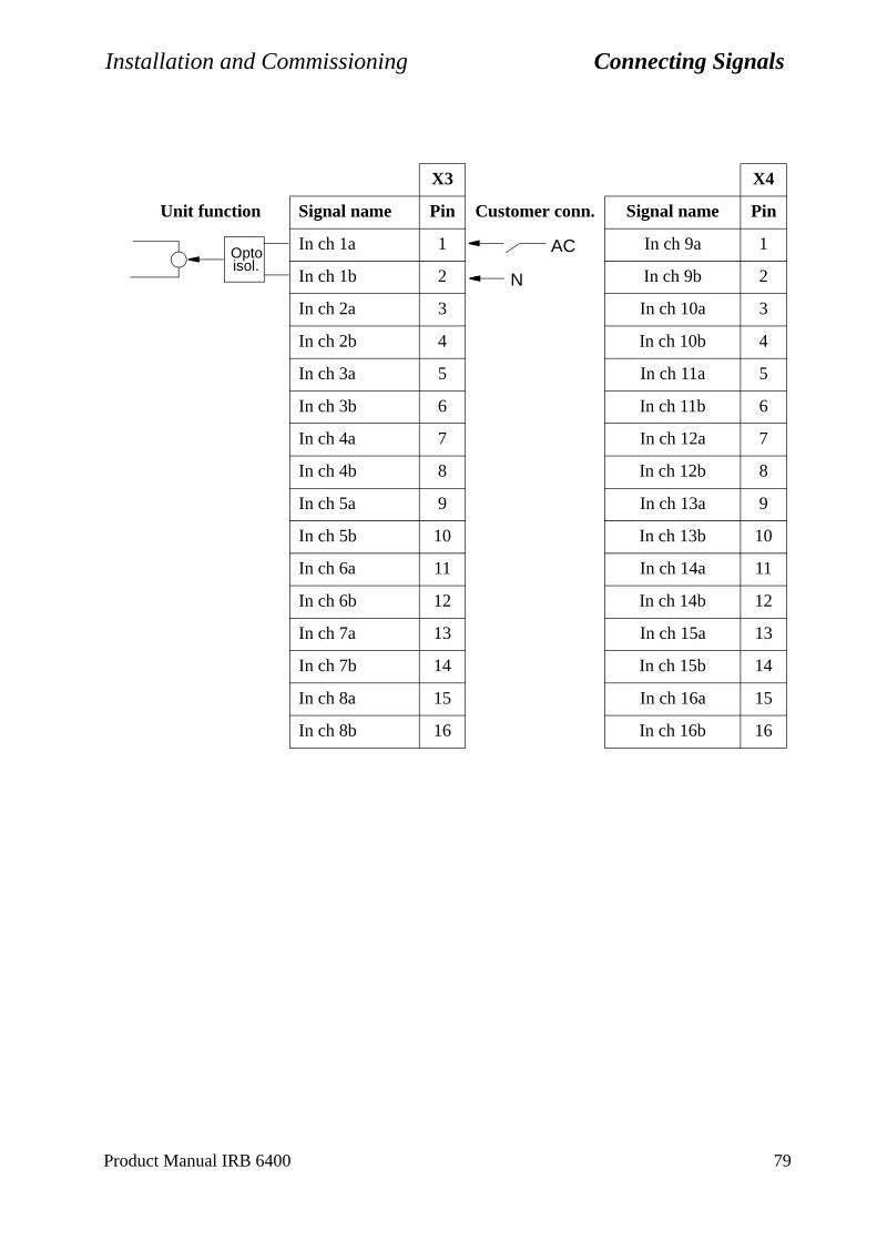
Installation and Commissioning Connecting Signals
X3 X4
Unit function Signal name Pin Customer conn. Signal name Pin
In ch 1a 1 In ch 9a 1
In ch 1b 2 In ch 9b 2
In ch 2a 3 In ch 10a 3
In ch 2b 4 In ch 10b 4
In ch 3a 5 In ch 11a 5
In ch 3b 6 In ch 11b 6
In ch 4a 7 In ch 12a 7
In ch 4b 8 In ch 12b 8
In ch 5a 9 In ch 13a 9
In ch 5b 10 In ch 13b 10
In ch 6a 11 In ch 14a 11
In ch 6b 12 In ch 14b 12
In ch 7a 13 In ch 15a 13
In ch 7b 14 In ch 15b 14
In ch 8a 15 In ch 16a 15
In ch 8b 16 In ch 16b 16
isol.Opto AC
N
Product Manual IRB 6400 79
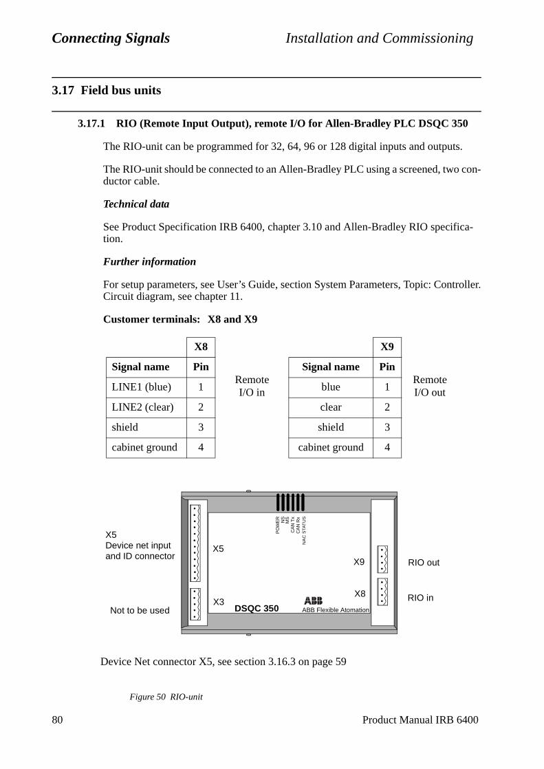
Connecting Signals Installation and Commissioning
ntroller.
3.17 Field bus units
3.17.1 RIO (Remote Input Output), remote I/O for Allen-Bradley PLC DSQC 350
The RIO-unit can be programmed for 32, 64, 96 or 128 digital inputs and outputs.
The RIO-unit should be connected to an Allen-Bradley PLC using a screened, two con-ductor cable.
Technical data
See Product Specification IRB 6400, chapter 3.10 and Allen-Bradley RIO specifica-tion.
Further information
For setup parameters, see User’s Guide, section System Parameters, Topic: CoCircuit diagram, see chapter 11.
Customer terminals: X8 and X9
Figure 50 RIO-unit
X8 X9
Signal name PinRemote I/O in
Signal name PinRemote I/O outLINE1 (blue) 1 blue 1
LINE2 (clear) 2 clear 2
shield 3 shield 3
cabinet ground 4 cabinet ground 4
Device Net connector X5, see section 3.16.3 on page 59
X5Device net inputand ID connector
Not to be used DSQC 350 ABB Flexible Atomation
X8
X9
X5
X3
CA
N R
xN
AC
STA
TU
S
CA
N T
xM
SN
SP
OW
ER
RIO in
RIO out
80 Product Manual IRB 6400
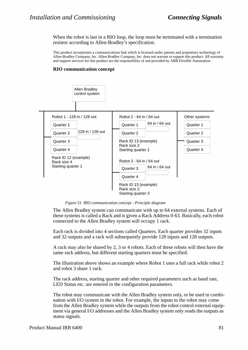
Installation and Commissioning Connecting Signals
h of robot
puts .
e the
bot 2
rate,
mbi-e uip-uts as
When the robot is last in a RIO loop, the loop must be terminated with a termination resistor according to Allen-Bradley’s specification.
This product incorporates a communications link which is licensed under patents and proprietary technology of Allen-Bradley Company, Inc. Allen-Bradley Company, Inc. does not warrant or support this product. All warranty and support services for this product are the responsibility of and provided by ABB Flexible Automation.
RIO communication concept
Figure 51 RIO communication concept - Principle diagram
The Allen Bradley system can communicate with up to 64 external systems. Eacthese systems is called a Rack and is given a Rack Address 0-63. Basically, eachconnected to the Allen Bradley system will occupy 1 rack.
Each rack is divided into 4 sections called Quarters. Each quarter provides 32 inand 32 outputs and a rack will subsequently provide 128 inputs and 128 outputs
A rack may also be shared by 2, 3 or 4 robots. Each of these robots will then havsame rack address, but different starting quarters must be specified.
The illustration above shows an example where Robot 1 uses a full rack while roand robot 3 share 1 rack.
The rack address, starting quarter and other required parameters such as baud LED Status etc. are entered in the configuration parameters.
The robot may communicate with the Allen Bradley system only, or be used in conation with I/O system in the robot. For example, the inputs to the robot may comfrom the Allen Bradley system while the outputs from the robot control external eqment via general I/O addresses and the Allen Bradley system only reads the outpstatus signals.
Allen Bradley control system
Robot 1 - 128 in / 128 out Robot 2 - 64 in / 64 out
128 in / 128 out
64 in / 64 out
Quarter 2
Quarter 3
Quarter 4
Quarter 1
Rack ID 12 (example) Rack size 4 Starting quarter 1
Quarter 2
Quarter 1
Rack ID 13 (example) Rack size 2 Starting quarter 1
Robot 3 - 64 in / 64 out
64 in / 64 out
Quarter 4
Quarter 3
Rack ID 13 (example) Rack size 2 Starting quarter 3
Quarter 2
Quarter 3
Quarter 4
Quarter 1
Other systems
Product Manual IRB 6400 81
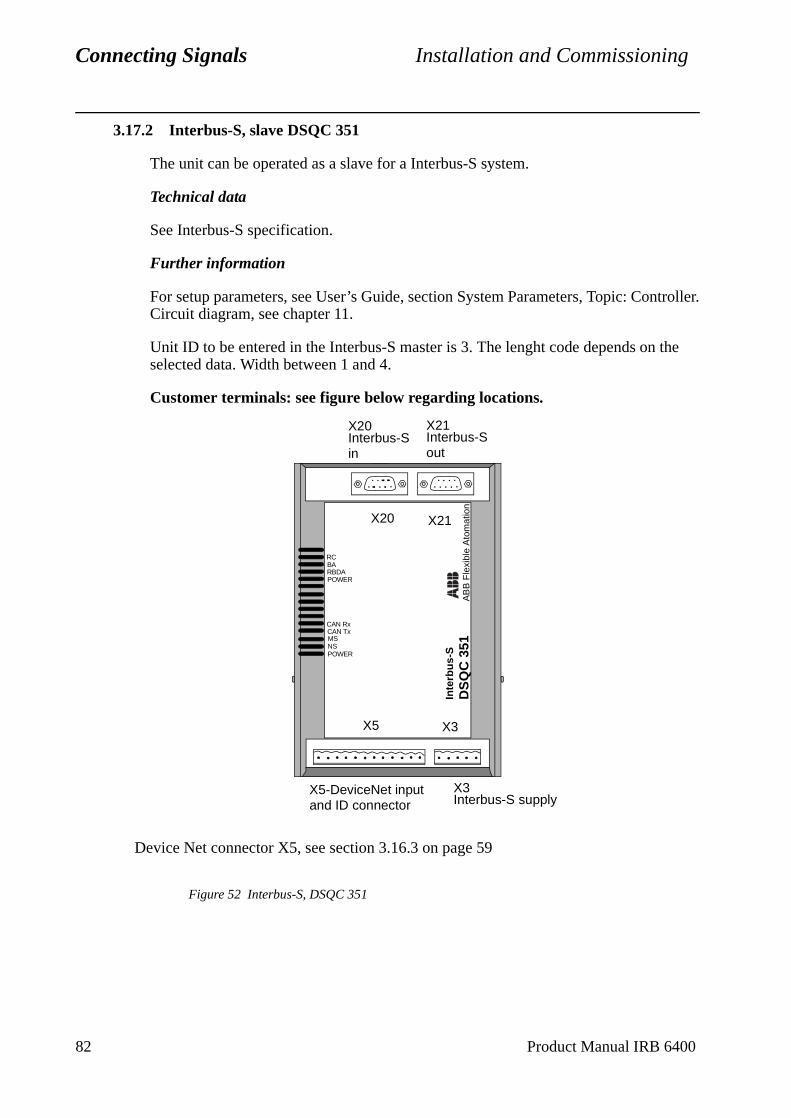
Connecting Signals Installation and Commissioning
ntroller.
the
3.17.2 Interbus-S, slave DSQC 351
The unit can be operated as a slave for a Interbus-S system.
Technical data
See Interbus-S specification.
Further information
For setup parameters, see User’s Guide, section System Parameters, Topic: CoCircuit diagram, see chapter 11.
Unit ID to be entered in the Interbus-S master is 3. The lenght code depends onselected data. Width between 1 and 4.
Customer terminals: see figure below regarding locations.
Figure 52 Interbus-S, DSQC 351
Device Net connector X5, see section 3.16.3 on page 59
X5-DeviceNet input X3Interbus-S supply
DS
QC
351
AB
B F
lexi
ble
Ato
mat
ion
Inte
rbu
s-S
X3X5
X21X20
POWER
CAN TxMSNS
RC
POWER
RBDABA
CAN Rx
and ID connector
X21Interbus-S out
X20Interbus-S in
82 Product Manual IRB 6400
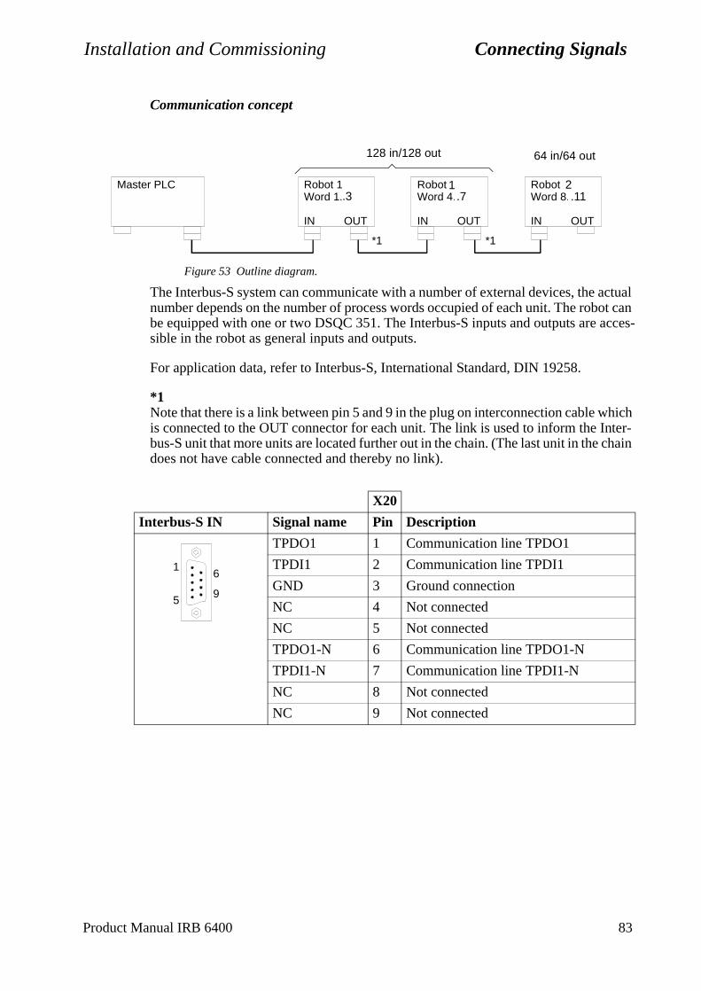
Installation and Commissioning Connecting Signals
Communication concept
Figure 53 Outline diagram.
The Interbus-S system can communicate with a number of external devices, the actual number depends on the number of process words occupied of each unit. The robot can be equipped with one or two DSQC 351. The Interbus-S inputs and outputs are acces-sible in the robot as general inputs and outputs.
For application data, refer to Interbus-S, International Standard, DIN 19258.
*1Note that there is a link between pin 5 and 9 in the plug on interconnection cable which is connected to the OUT connector for each unit. The link is used to inform the Inter-bus-S unit that more units are located further out in the chain. (The last unit in the chain does not have cable connected and thereby no link).
X20
Interbus-S IN Signal name Pin Description
TPDO1 1 Communication line TPDO1
TPDI1 2 Communication line TPDI1
GND 3 Ground connection
NC 4 Not connected
NC 5 Not connected
TPDO1-N 6 Communication line TPDO1-N
TPDI1-N 7 Communication line TPDI1-N
NC 8 Not connected
NC 9 Not connected
IN OUT IN OUT IN OUT
*1 *1
Robot 1Word 1.3
Robot 2Word 4.7
Robot 3Word 8.11
Master PLC.3 .7
1.11
2
64 in/64 out128 in/128 out
5
1
9
6
Product Manual IRB 6400 83
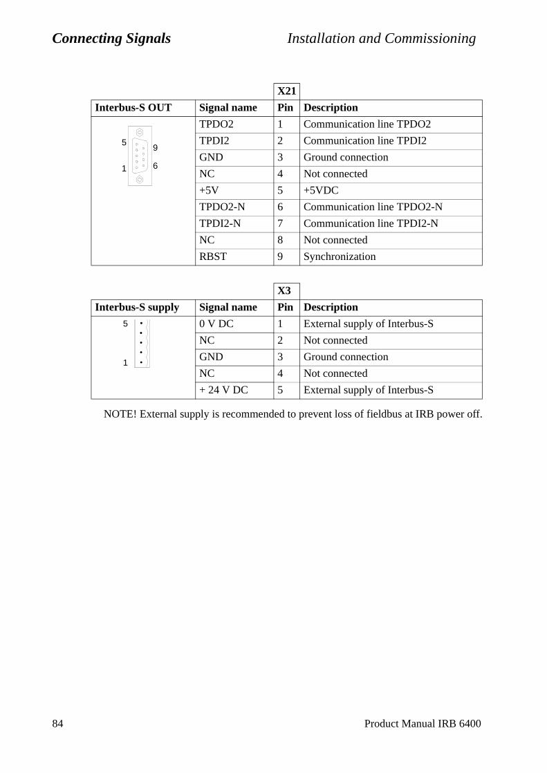
Connecting Signals Installation and Commissioning
NOTE! External supply is recommended to prevent loss of fieldbus at IRB power off.
X21
Interbus-S OUT Signal name Pin Description
TPDO2 1 Communication line TPDO2
TPDI2 2 Communication line TPDI2
GND 3 Ground connection
NC 4 Not connected
+5V 5 +5VDC
TPDO2-N 6 Communication line TPDO2-N
TPDI2-N 7 Communication line TPDI2-N
NC 8 Not connected
RBST 9 Synchronization
X3
Interbus-S supply Signal name Pin Description
0 V DC 1 External supply of Interbus-S
NC 2 Not connected
GND 3 Ground connection
NC 4 Not connected
+ 24 V DC 5 External supply of Interbus-S
1
59
6
1
5
84 Product Manual IRB 6400
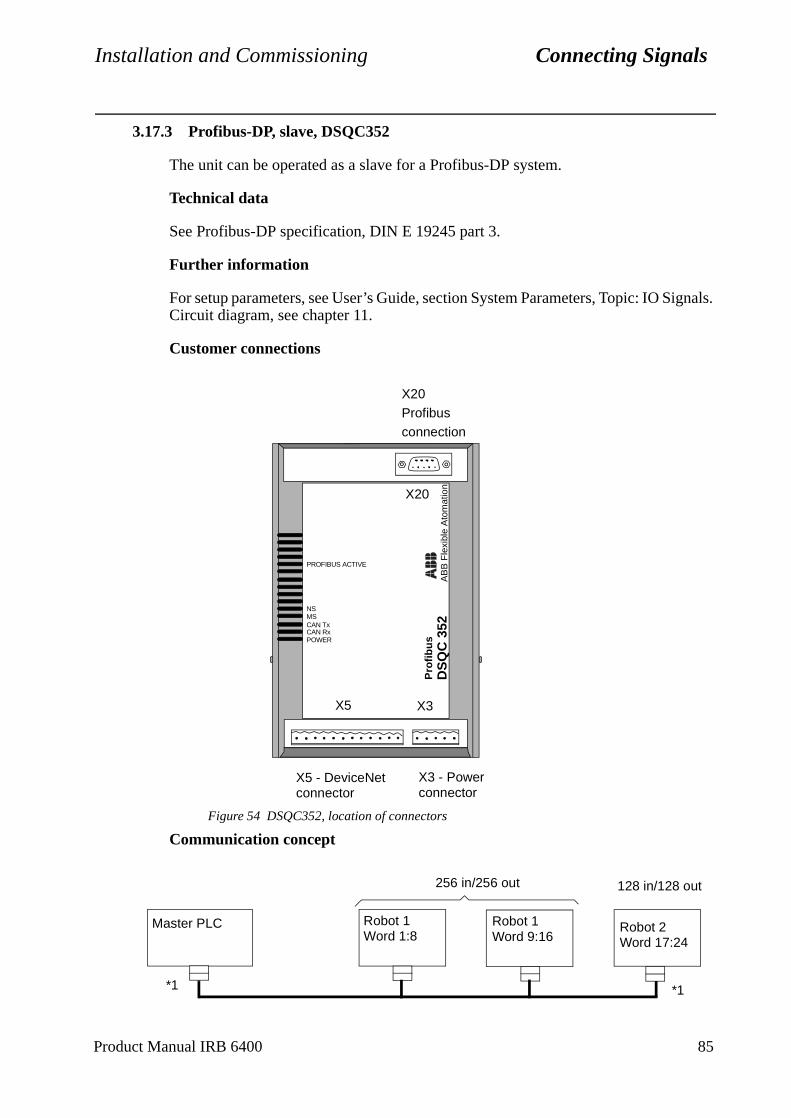
Installation and Commissioning Connecting Signals
ignals.
3.17.3 Profibus-DP, slave, DSQC352
The unit can be operated as a slave for a Profibus-DP system.
Technical data
See Profibus-DP specification, DIN E 19245 part 3.
Further information
For setup parameters, see User’s Guide, section System Parameters, Topic: IO SCircuit diagram, see chapter 11.
Customer connections
Figure 54 DSQC352, location of connectors
Communication concept
X20Profibusconnection
X5 - DeviceNetconnector
X3 - Powerconnector
DS
QC
352
AB
B F
lexi
ble
Ato
mat
ion
CAN TxMS
POWERCAN Rx
PROFIBUS ACTIVE
X20
X5 X3
Pro
fib
us
NS
.3 .71
.112
128 in/128 out256 in/256 out
Robot 2Word 17:24
Robot 1Word 9:16
Robot 1Word 1:8
Master PLC
*1 *1
Product Manual IRB 6400 85
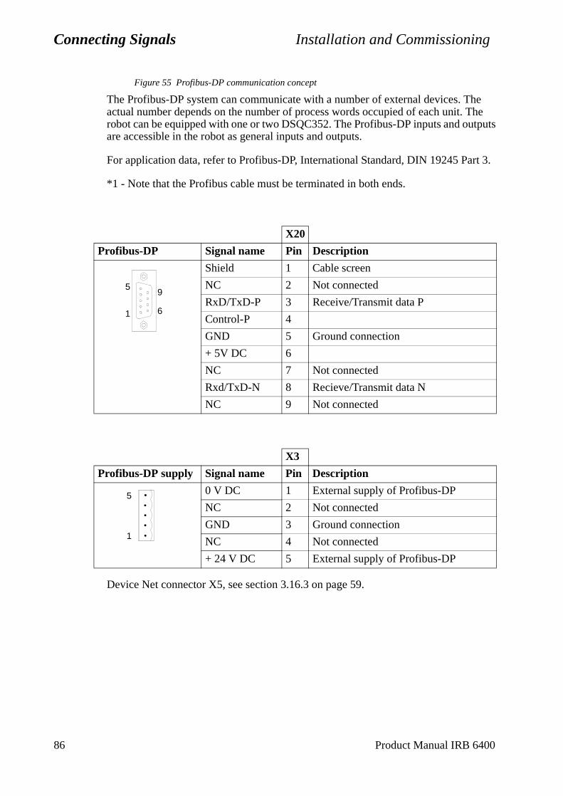
Connecting Signals Installation and Commissioning
Figure 55 Profibus-DP communication concept
The Profibus-DP system can communicate with a number of external devices. The actual number depends on the number of process words occupied of each unit. The robot can be equipped with one or two DSQC352. The Profibus-DP inputs and outputs are accessible in the robot as general inputs and outputs.
For application data, refer to Profibus-DP, International Standard, DIN 19245 Part 3.
*1 - Note that the Profibus cable must be terminated in both ends.
Device Net connector X5, see section 3.16.3 on page 59.
X20
Profibus-DP Signal name Pin Description
Shield 1 Cable screen
NC 2 Not connected
RxD/TxD-P 3 Receive/Transmit data P
Control-P 4
GND 5 Ground connection
+ 5V DC 6
NC 7 Not connected
Rxd/TxD-N 8 Recieve/Transmit data N
NC 9 Not connected
X3
Profibus-DP supply Signal name Pin Description
0 V DC 1 External supply of Profibus-DP
NC 2 Not connected
GND 3 Ground connection
NC 4 Not connected
+ 24 V DC 5 External supply of Profibus-DP
1
59
6
1
5
86 Product Manual IRB 6400
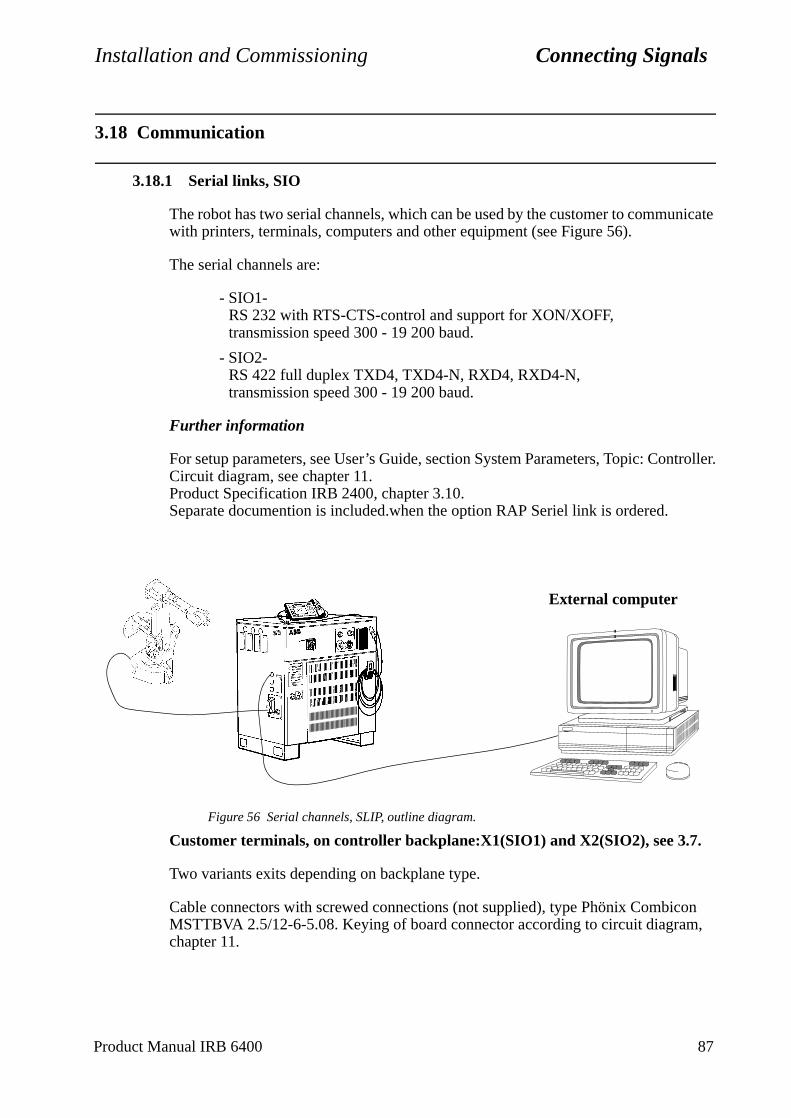
Installation and Commissioning Connecting Signals
troller.
on ,
3.18 Communication
3.18.1 Serial links, SIO
The robot has two serial channels, which can be used by the customer to communicate with printers, terminals, computers and other equipment (see Figure 56).
The serial channels are:
- SIO1-RS 232 with RTS-CTS-control and support for XON/XOFF, transmission speed 300 - 19 200 baud.
- SIO2-RS 422 full duplex TXD4, TXD4-N, RXD4, RXD4-N,transmission speed 300 - 19 200 baud.
Further information
For setup parameters, see User’s Guide, section System Parameters, Topic: ConCircuit diagram, see chapter 11.Product Specification IRB 2400, chapter 3.10.Separate documention is included.when the option RAP Seriel link is ordered.
Figure 56 Serial channels, SLIP, outline diagram.
Customer terminals, on controller backplane:X1(SIO1) and X2(SIO2), see 3.7.
Two variants exits depending on backplane type.
Cable connectors with screwed connections (not supplied), type Phönix CombicMSTTBVA 2.5/12-6-5.08. Keying of board connector according to circuit diagramchapter 11.
External computer
Product Manual IRB 6400 87

Connecting Signals Installation and Commissioning
DSCQ 330 (screw terminals)
DSQC 369 (D-sub connectors)
Explanation of signals:TXD=Transmit Data, RTS=Request To Send, RXD=Receive Data, CTS=Clear To Send, DTR=Data Terminal Ready, DSR=Data Set Ready, DATA=Data Signals in Half Duplex Mode, DCLK=Data Transmission Clock.
X1 X2
Pin Signal Pin Signal
1 TXD 1 TXD
2 RTS N 2 TXD N
3 0V 3 0V
4 RXD 4 RXD
5 CTS N 5 RXD N
6 0V 6 0V
7 DTR 7 DATA
8 DSR 8 DATA N
9 0V 9 0V
10 10 DCLK
11 11 DCLK N
12 12 0V
X1 X2
Pin Signal Pin Signal
1 1 TXD
2 RXD 2 TXD N
3 TXD 3 RXD
4 DTR 4 RXD N
5 0 V 5 0 V
6 DSR 6 DATA
7 RTS N 7 DATA N
8 CTS N 8 DCLK
9 9 DCLK N
88 Product Manual IRB 6400
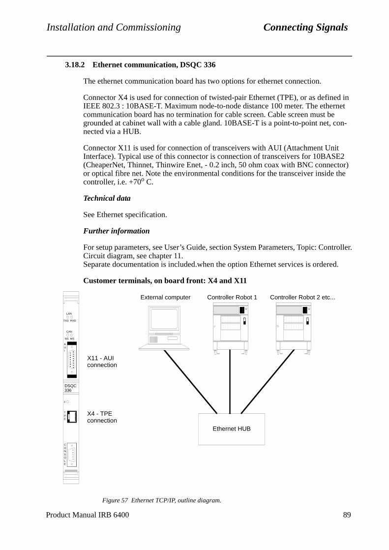
Installation and Commissioning Connecting Signals
troller.
d.
3.18.2 Ethernet communication, DSQC 336
The ethernet communication board has two options for ethernet connection.
Connector X4 is used for connection of twisted-pair Ethernet (TPE), or as defined in IEEE 802.3 : 10BASE-T. Maximum node-to-node distance 100 meter. The ethernet communication board has no termination for cable screen. Cable screen must be grounded at cabinet wall with a cable gland. 10BASE-T is a point-to-point net, con-nected via a HUB.
Connector X11 is used for connection of transceivers with AUI (Attachment Unit Interface). Typical use of this connector is connection of transceivers for 10BASE2 (CheaperNet, Thinnet, Thinwire Enet, - 0.2 inch, 50 ohm coax with BNC connector) or optical fibre net. Note the environmental conditions for the transceiver inside the controller, i.e. +70o C.
Technical data
See Ethernet specification.
Further information
For setup parameters, see User’s Guide, section System Parameters, Topic: ConCircuit diagram, see chapter 11.Separate documentation is included.when the option Ethernet services is ordere
Customer terminals, on board front: X4 and X11
Figure 57 Ethernet TCP/IP, outline diagram.
DSQC336
LAN
TXD RXD
CAN
NS MS
AUI
F
TPE
CONSOLE
X11 - AUIconnection
X4 - TPEconnection
Ethernet HUB
External computer Controller Robot 1 Controller Robot 2 etc...
Product Manual IRB 6400 89
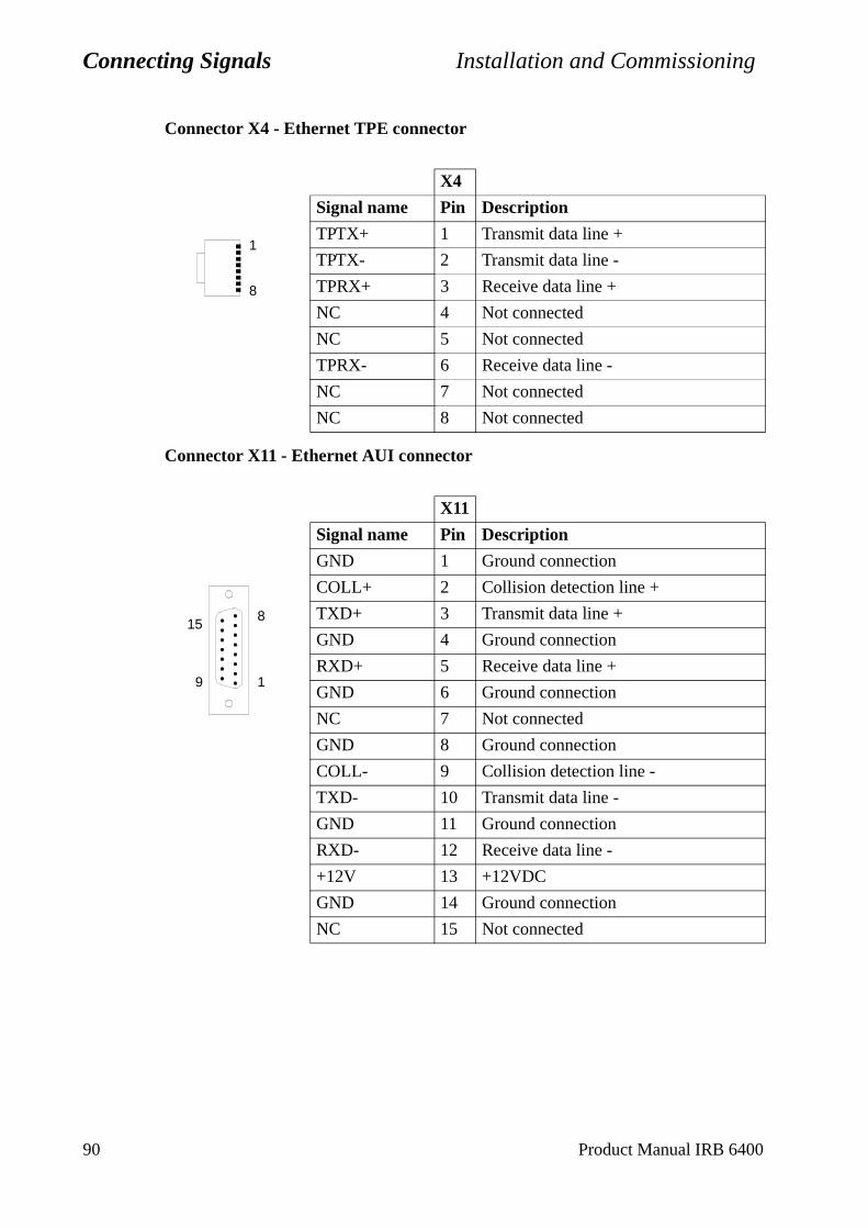
Connecting Signals Installation and Commissioning
Connector X4 - Ethernet TPE connector
Connector X11 - Ethernet AUI connector
X4
Signal name Pin Description
TPTX+ 1 Transmit data line +
TPTX- 2 Transmit data line -
TPRX+ 3 Receive data line +
NC 4 Not connected
NC 5 Not connected
TPRX- 6 Receive data line -
NC 7 Not connected
NC 8 Not connected
X11
Signal name Pin Description
GND 1 Ground connection
COLL+ 2 Collision detection line +
TXD+ 3 Transmit data line +
GND 4 Ground connection
RXD+ 5 Receive data line +
GND 6 Ground connection
NC 7 Not connected
GND 8 Ground connection
COLL- 9 Collision detection line -
TXD- 10 Transmit data line -
GND 11 Ground connection
RXD- 12 Receive data line -
+12V 13 +12VDC
GND 14 Ground connection
NC 15 Not connected
1
8
1
815
9
90 Product Manual IRB 6400
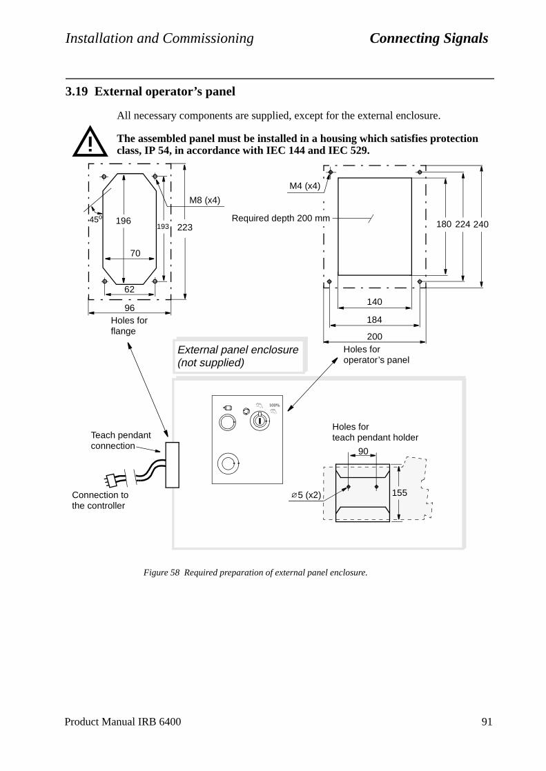
Installation and Commissioning Connecting Signals
3.19 External operator’s panel
All necessary components are supplied, except for the external enclosure.
The assembled panel must be installed in a housing which satisfies protection class, IP 54, in accordance with IEC 144 and IEC 529.
Figure 58 Required preparation of external panel enclosure.
184
224180
140
193196
70
62
45o
External panel enclosure(not supplied)
M8 (x4)
Connection to
Holes for flange
Holes for operator’s panel
Holes forteach pendant holder
the controller
90
1555 (x2)
100%
Teach pendantconnection
200
240Required depth 200 mm
M4 (x4)
96
223
Product Manual IRB 6400 91

Connecting Signals Installation and Commissioning
92 Product Manual IRB 6400
Installation and Commissioning Installing the Control Program
. the
ed .
me em
4 Installing the Control Program
The robot memory is battery-backed, which means that the control program and set-tings (pre-installed) are saved when the power supply to the robot is switched off.
The robot might be delivered without software installed and the memory back-up bat-teries disconnected to ensure maximum battery capacity after installation. If so, connect the batteries and start the installation according to 4.1.1.
4.1 System diskettes
• Key disk (one disk) Each robot needs an unique key disk with selected options and IRB typeRobots within the same family (i.e. different variants of the robot) can usesame key disk with a licence number.
• System packBaseWare OS, all options and ProcessWare.
• Controller parameters (one disk)At delivery, it includes I/O configuration according to order specification.At commissioning all parameters are stored.
• Manipulator parameters (one disk)Includes sync. offsets from manufacturing calibration.
4.1.1 Installation procedure
1. Perform a cold start on the system.
2. Insert the “Key disk” when displayed on the teach pendant.
3. Follow information displayed on the teach pendant. Keep attention to promptSystem pack disk number (all diskettes are not used at the same installation)
During the installation following menus appears:
- Silent = The installation follows the information on the Key disk.
- Add Opt =The installation follows the Key disk but further options,not included in the system pack, are possible to add.
- Query = Questions about changing language, robot type (within the safamily), gain access to service mode, see User’s Guide, SystParameters etc. are coming up. Makes it possible to exclude options but not add more than included in the Key disk.
If Query is selected, make sure that the correct robot type is entered. If not, this will affect the safety function Reduced speed 250 mm/s.
Product Manual IRB 6400 93
Installing the Control Program Installation and Commissioning
If Query is selected, make sure that all required options are installed. Note that some of these options also require installation of other options. Rejecting of pro-posed options during installation may cause an incomplete robot installation.
4. The robot performs a warm start when installation is finished.
Wait until the welcome window appears on the display before doing anything. The warm start can take up to 2 minutes after the installation display ready.
5. Load the specific installation parameters from the Controller Parameter disk or corresponding.
After the control program has been installed, the diskettes should be stored in a safe place in accordance with the general rules for diskette storage. Do not store the diskettes inside the controller to avoid damaged from heat and magnetic fields.
6. Conclude the installation with updating the revolution counters according to section 2.13.2.
4.2 Calibration of the manipulator
Calibrate the manipulator according to section 2.13.
4.3 Cold start
To install the control program in a robot already in operation the memory must be emp-tied. Besides disconnecting the batteries for a few minutes, the following method can be used:
1. Select the Service window
2. Select File: Restart
3. Then enter the numbers 1 3 4 6 7 9
4. The fifth function key changes to C-Start (Cold start)
5. Press the key C-Start
It will take quite some time to perform a Cold start. Just wait until the robot starts the Installation dialog, see 4.1.1.
Do not touch any key, joystick, enable device or emergency stop until you are prompted to press any key.
94 Product Manual IRB 6400
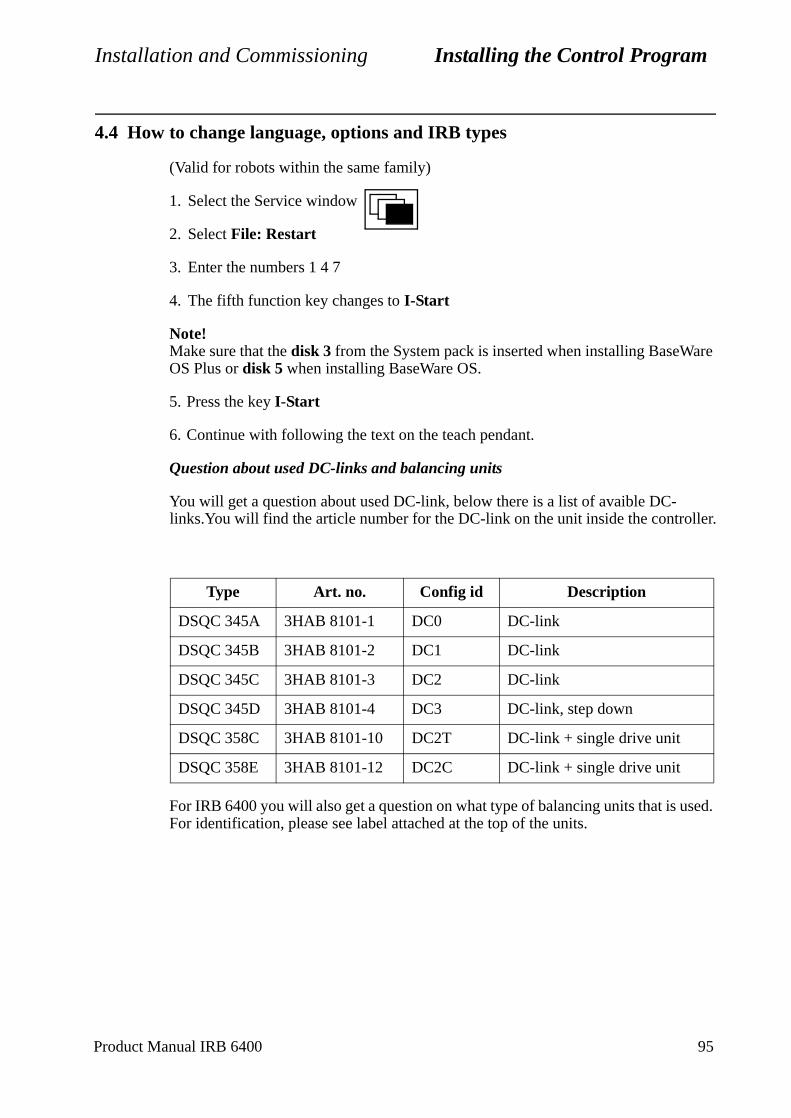
Installation and Commissioning Installing the Control Program
4.4 How to change language, options and IRB types
(Valid for robots within the same family)
1. Select the Service window
2. Select File: Restart
3. Enter the numbers 1 4 7
4. The fifth function key changes to I-Start
Note!Make sure that the disk 3 from the System pack is inserted when installing BaseWare OS Plus or disk 5 when installing BaseWare OS.
5. Press the key I-Start
6. Continue with following the text on the teach pendant.
Question about used DC-links and balancing units
You will get a question about used DC-link, below there is a list of avaible DC-links.You will find the article number for the DC-link on the unit inside the controller.
For IRB 6400 you will also get a question on what type of balancing units that is used. For identification, please see label attached at the top of the units.
Type Art. no. Config id Description
DSQC 345A 3HAB 8101-1 DC0 DC-link
DSQC 345B 3HAB 8101-2 DC1 DC-link
DSQC 345C 3HAB 8101-3 DC2 DC-link
DSQC 345D 3HAB 8101-4 DC3 DC-link, step down
DSQC 358C 3HAB 8101-10 DC2T DC-link + single drive unit
DSQC 358E 3HAB 8101-12 DC2C DC-link + single drive unit
Product Manual IRB 6400 95
Installing the Control Program Installation and Commissioning
4.5 How to use the disk, Manipulator Parameters
The S4C controller does not contain any calibration information at delivery (Robot Not Calibrated shown on the teach pendant).
Once the Manipulator Parameter disk contents has been loaded to the controller as in one of the two cases described below, should a new parameter back-up be saved on the disk, Controller Parameter. After saving the new parameters on the disk, Controller Parameter the Manipulator Parameter disk is no longer needed.
4.6 Robot delivered with software installed
In this case the basic parameters are already installed.
Load the calibration offset values from the disk, Manipulator Parameters.
1. Select File: Add or Replace Parameter.
Do not select Add new or Load Saved Parameters.
2. Press OK.
3. Save the new parameters according to section 4.8.
4.7 Robot delivered without software installed
In this case a complete cold start is necessary, remember to connect the back-up batter-ies.
The basic parameters are loaded at the cold start. The delivery specific I/O configura-tion is loaded from the disk, Controller Parameters.
1. Select File:Add New Parameters.
2. Press OK.
3. Load the calibration offset values from the disk, Manipulator Parameters.
4. Select File:Add or Replace Parameter.
Do not select Add new or Load Saved Parameters.
5. Press OK.
6. Save the new parameters according to section 4.8.
96 Product Manual IRB 6400

Installation and Commissioning Installing the Control Program
r’s
4.8 Saving the parameters on the Controller Parameter disk
1. Insert the disk, Controller Parameter.
2. Select File:Save All As.
For more detailed information regarding saving and loading parameters see UseGuide, System Parameters.
Product Manual IRB 6400 97

Installing the Control Program Installation and Commissioning
98 Product Manual IRB 6400

Installation and Commissioning External Axes
5 External Axes
5.1 General
External axes are controlled by internal or external (equals to non ABB) drive units. Internal drive units are mounted either inside the robot cabinet or in a separate external cabinet. External drive units are mounted in a user designed cabinet.
A maximum number of 6 external axes can be controlled by S4C. Internal drive units mounted in a separate cabinet cannot be combined with external drive units.
The drive and measurement systems each consist of two systems. Each system is connected to the CPU boards via a serial communication link.
A number of template configuration files are supplied with the system. The configura-tion files are optimum designed concerning system behaviour and performance of the axes. When installing external axes it is important to design installations, so a combi-nation of standard files can be used.
Axes connected to Measurement System 1 can use Drive System 2 and vice versa. Allowed combinations - see configuration files section 5.3.5.
Product Manual IRB 6400 99
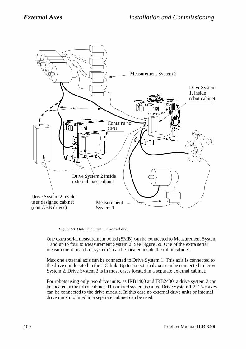
External Axes Installation and Commissioning
Figure 59 Outline diagram, external axes.
One extra serial measurement board (SMB) can be connected to Measurement System 1 and up to four to Measurement System 2. See Figure 59. One of the extra serial measurement boards of system 2 can be located inside the robot cabinet.
Max one external axis can be connected to Drive System 1. This axis is connected to the drive unit located in the DC-link. Up to six external axes can be connected to Drive System 2. Drive System 2 is in most cases located in a separate external cabinet.
For robots using only two drive units, as IRB1400 and IRB2400, a drive system 2 can be located in the robot cabinet. This mixed system is called Drive System 1.2 . Two axes can be connected to the drive module. In this case no external drive units or internal drive units mounted in a separate cabinet can be used.
alt.
Measurement System 1
Drive System 2 inside external axes cabinet
Measurement System 2
Drive System 1, inside robot cabinet
Contains noCPU
Drive System 2 inside user designed cabinet(non ABB drives)
100 Product Manual IRB 6400
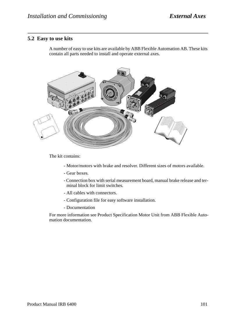
Installation and Commissioning External Axes
5.2 Easy to use kits
A number of easy to use kits are available by ABB Flexible Automation AB. These kits contain all parts needed to install and operate external axes.
The kit contains:
- Motor/motors with brake and resolver. Different sizes of motors available.
- Gear boxes.
- Connection box with serial measurement board, manual brake release and ter-minal block for limit switches.
- All cables with connectors.
- Configuration file for easy software installation.
- Documentation
For more information see Product Specification Motor Unit from ABB Flexible Auto-mation documentation.
Product Manual IRB 6400 101
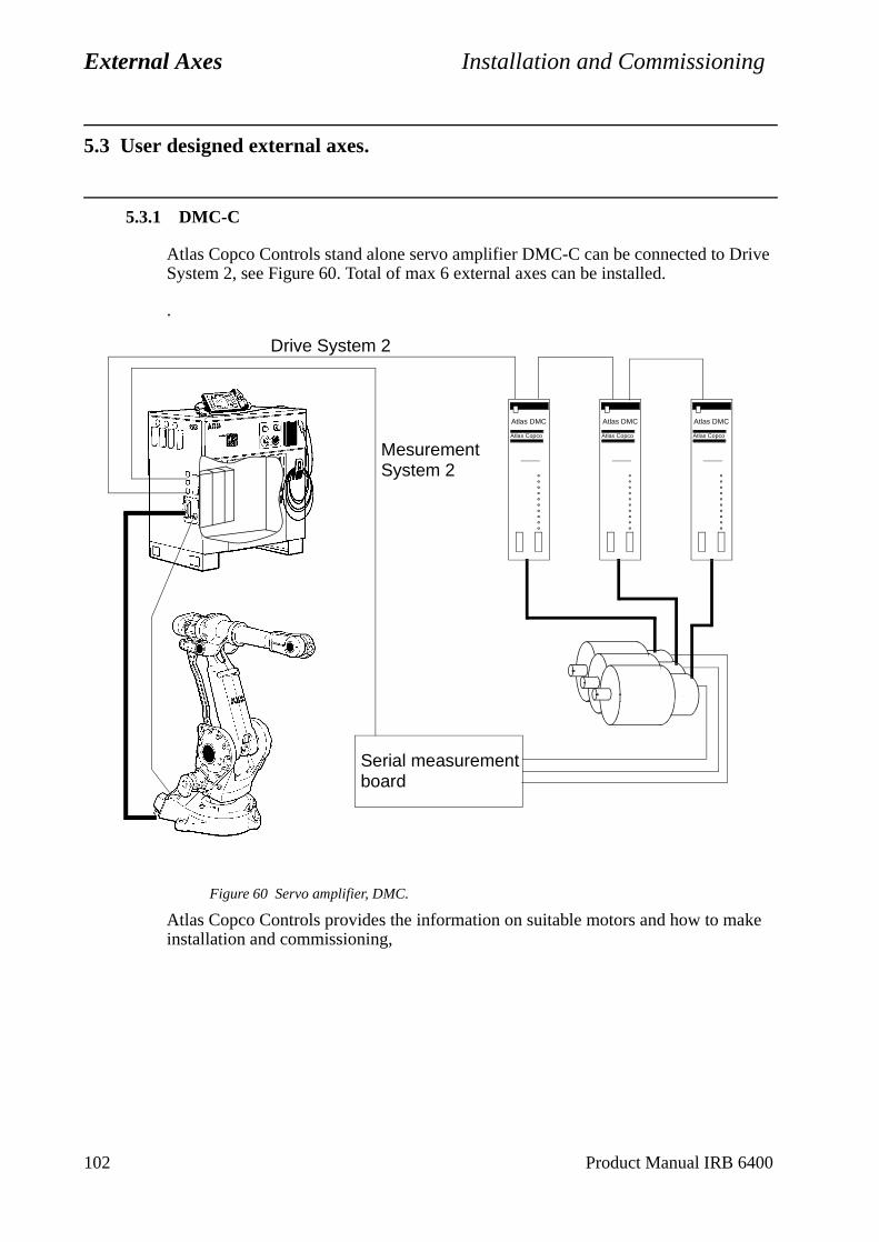
External Axes Installation and Commissioning
5.3 User designed external axes.
5.3.1 DMC-C
Atlas Copco Controls stand alone servo amplifier DMC-C can be connected to Drive System 2, see Figure 60. Total of max 6 external axes can be installed.
.
Figure 60 Servo amplifier, DMC.
Atlas Copco Controls provides the information on suitable motors and how to make installation and commissioning,
Atlas DMC
Atlas Copco
Atlas DMC
Atlas Copco
Atlas DMC
Atlas Copco
Serial measurementboard
Drive System 2
Mesurement System 2
102 Product Manual IRB 6400
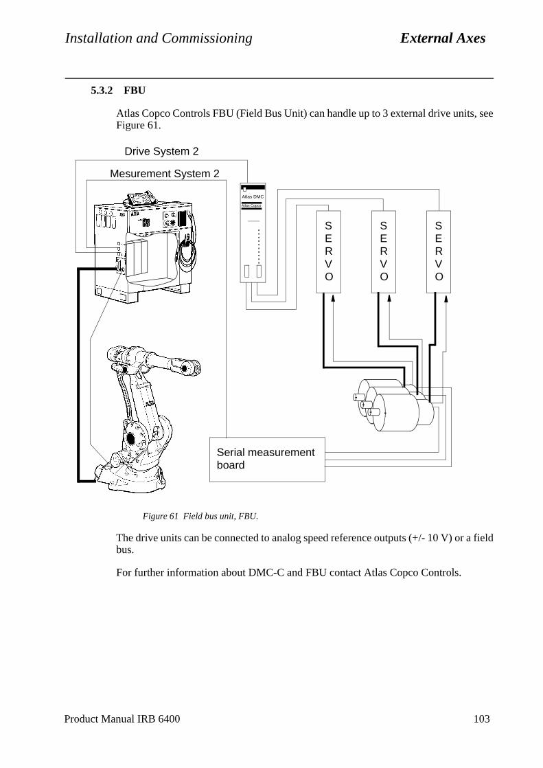
Installation and Commissioning External Axes
5.3.2 FBU
Atlas Copco Controls FBU (Field Bus Unit) can handle up to 3 external drive units, see Figure 61.
Figure 61 Field bus unit, FBU.
The drive units can be connected to analog speed reference outputs (+/- 10 V) or a field bus.
For further information about DMC-C and FBU contact Atlas Copco Controls.
Atlas DMC
Atlas Copco
Serial measurementboard
SERVO
SERVO
SERVO
Drive System 2
Mesurement System 2
Product Manual IRB 6400 103
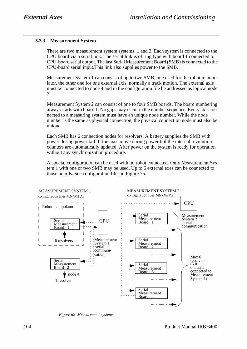
External Axes Installation and Commissioning
5.3.3 Measurement System
There are two measurement system systems, 1 and 2. Each system is connected to the CPU board via a serial link. The serial link is of ring type with board 1 connected to CPU-board serial output. The last Serial Measurement Board (SMB) is connected to the CPU-board serial input.This link also supplies power to the SMB.
Measurement System 1 can consist of up to two SMB, one used for the robot manipu-lator, the other one for one external axis, normally a track motion. The external axis must be connected to node 4 and in the configuration file be addressed as logical node 7.
Measurement System 2 can consist of one to four SMB boards. The board numbering always starts with board 1. No gaps may occur in the number sequence. Every axis con-nected to a measuring system must have an unique node number. While the node number is the same as physical connection, the physical connection node must also be unique.
Each SMB has 6 connection nodes for resolvers. A battery supplies the SMB with power during power fail. If the axes move during power fail the internal revolution counters are automatically updated. After power on the system is ready for operation without any synchronization procedure.
A special configuration can be used with no robot connected. Only Measurement Sys-tem 1 with one or two SMB may be used. Up to 6 external axes can be connected to those boards. See configuration files in Figure 75.
Figure 62 Measurement systems.
MEASUREMENT SYSTEM 1
MeasurementSystem 1 serialcommuni-
SerialMeasurementBoard 1
SerialMeasurementBoard 2
Robot manipulator
6 resolvers
1 resolver
node 4
MEASUREMENT SYSTEM 2
MeasurementSystem 2 serialS
communication
SerialMeasurementBoard 1
SerialMeasurementBoard 3
SerialMeasurementBoard 2
SerialMeasurementBoard 4
Max 6 resolvers(5 if one axisconnected to
).Measurement
configuration files MN4M1Dx configuration files MNxM2Dx
System 1)
cation
CPU
CPU
104 Product Manual IRB 6400
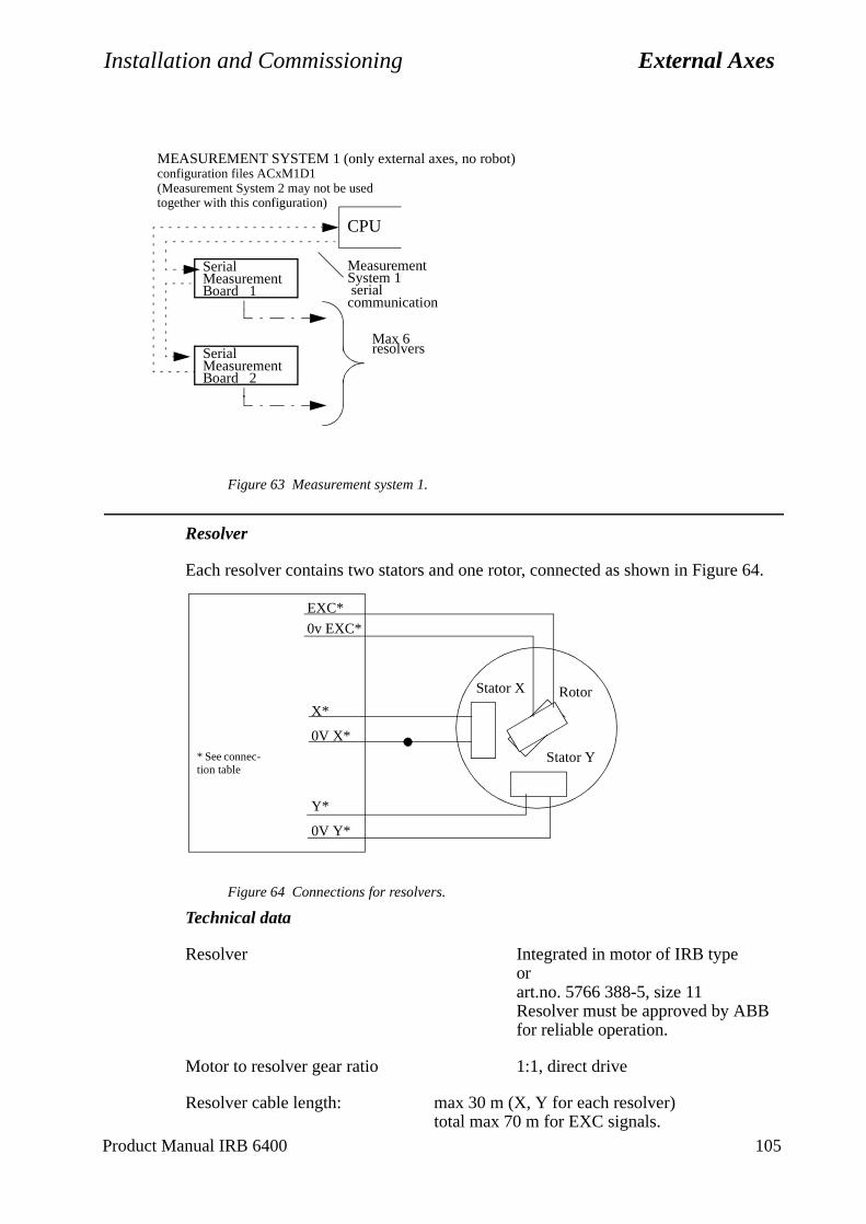
Installation and Commissioning External Axes
Figure 63 Measurement system 1.
Resolver
Each resolver contains two stators and one rotor, connected as shown in Figure 64.
Figure 64 Connections for resolvers.
Technical data
Resolver Integrated in motor of IRB typeorart.no. 5766 388-5, size 11Resolver must be approved by ABBfor reliable operation.
Motor to resolver gear ratio 1:1, direct drive
Resolver cable length: max 30 m (X, Y for each resolver)total max 70 m for EXC signals.
MEASUREMENT SYSTEM 1 (only external axes, no robot)
Measurement
serialSystem 1
communication
SerialMeasurementBoard 1
SerialMeasurementBoard 2
Max 6 resolvers
(Measurement System 2 may not be used together with this configuration)
configuration files ACxM1D1
CPU
* See connec-tion table
Stator X
Stator Y
Rotor
EXC*
0v EXC*
X*
0V X*
Y*
0V Y*
Product Manual IRB 6400 105
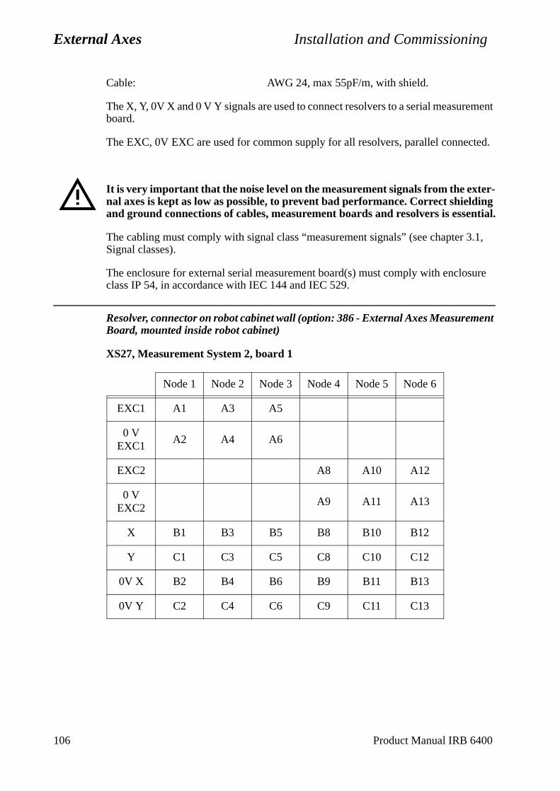
External Axes Installation and Commissioning
.1,
sure
Cable: AWG 24, max 55pF/m, with shield.
The X, Y, 0V X and 0 V Y signals are used to connect resolvers to a serial measurement board.
The EXC, 0V EXC are used for common supply for all resolvers, parallel connected.
It is very important that the noise level on the measurement signals from the exter-nal axes is kept as low as possible, to prevent bad performance. Correct shielding and ground connections of cables, measurement boards and resolvers is essential.
The cabling must comply with signal class “measurement signals” (see chapter 3Signal classes).
The enclosure for external serial measurement board(s) must comply with encloclass IP 54, in accordance with IEC 144 and IEC 529.
Resolver, connector on robot cabinet wall (option: 386 - External Axes Measurement Board, mounted inside robot cabinet)
XS27, Measurement System 2, board 1
Node 1 Node 2 Node 3 Node 4 Node 5 Node 6
EXC1 A1 A3 A5
0 V EXC1
A2 A4 A6
EXC2 A8 A10 A12
0 V EXC2
A9 A11 A13
X B1 B3 B5 B8 B10 B12
Y C1 C3 C5 C8 C10 C12
0V X B2 B4 B6 B9 B11 B13
0V Y C2 C4 C6 C9 C11 C13
106 Product Manual IRB 6400
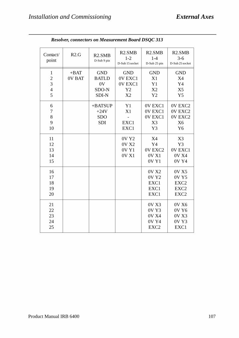
Installation and Commissioning External Axes
Resolver, connectors on Measurement Board DSQC 313
Contact/point
R2.G R2.SMBD-Sub 9 pin
R2.SMB 1-2
D-Sub 15 socket
R2.SMB 1-4
D-Sub 25 pin
R2.SMB 3-6
D-Sub 25 socket
12345
+BAT0V BAT
GNDBATLD
0VSDO-NSDI-N
GND0V EXC10V EXC1
Y2X2
GNDX1Y1X2Y2
GNDX4Y4X5Y5
678910
+BATSUP+24VSDOSDI
Y1X1-
EXC1EXC1
0V EXC10V EXC10V EXC1
X3Y3
0V EXC20V EXC20V EXC2
X6Y6
1112131415
0V Y20V X20V Y10V X1
X4Y4
0V EXC20V X10V Y1
X3Y3
0V EXC10V X40V Y4
1617181920
0V X20V Y2EXC1EXC1EXC1
0V X50V Y5EXC2EXC2EXC2
2122232425
0V X30V Y30V X40V Y4EXC2
0V X60V Y60V X30V Y3EXC1
Product Manual IRB 6400 107
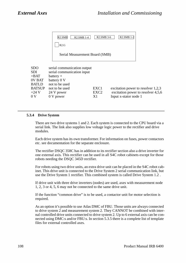
External Axes Installation and Commissioning
is
cted inter-e con-plate
SDO serial communication outputSDI serial communication input+BAT battery +0V BAT battery 0 VBATLD not to be usedBATSUP not to be used EXC1 excitation power to resolver 1,2,3+24 V 24 V power EXC2 excitation power to resolver 4,5,60 V 0 V power X1 Input x-stator node 1
5.3.4 Drive System
There are two drive systems 1 and 2. Each system is connected to the CPU board via a serial link. The link also supplies low voltage logic power to the rectifier and drive modules.
Each drive system has its own transformer. For information on fuses, power contactors etc. see documentation for the separate enclosure.
The rectifier DSQC 358C has in addition to its rectifier section also a drive inverter for one external axis. This rectifier can be used in all S4C robot cabinets except for those robots needing the DSQC 345D rectifier.
For robots using two drive units, an extra drive unit can be placed in the S4C robot cab-inet. This drive unit is connected to the Drive System 2 serial communication link, but use the Drive System 1 rectifier. This combined system is called Drive System 1.2 .
If drive unit with three drive inverters (nodes) are used, axes with measurement node 1, 2, 3 or 4, 5, 6 may not be connected to the same drive unit.
If the function “common drive” is to be used, a contactor unit for motor selection required.
As an option it’s possible to use Atlas DMC of FBU. Those units are always conneto drive system 2 and measurement system 2. They CANNOT be combined withnal controlled drive units connected to drive system 2. Up to 6 external axis can bnected using DMC:s and/or FBU:s. In section 5.3.5 there is a complete list of temfiles for external controlled axes.
R2.SMB 1-4 R2.SMB 3-6 R2.SMB 1-2R2.SMB
R2.G
Serial Measurement Board (SMB)
108 Product Manual IRB 6400
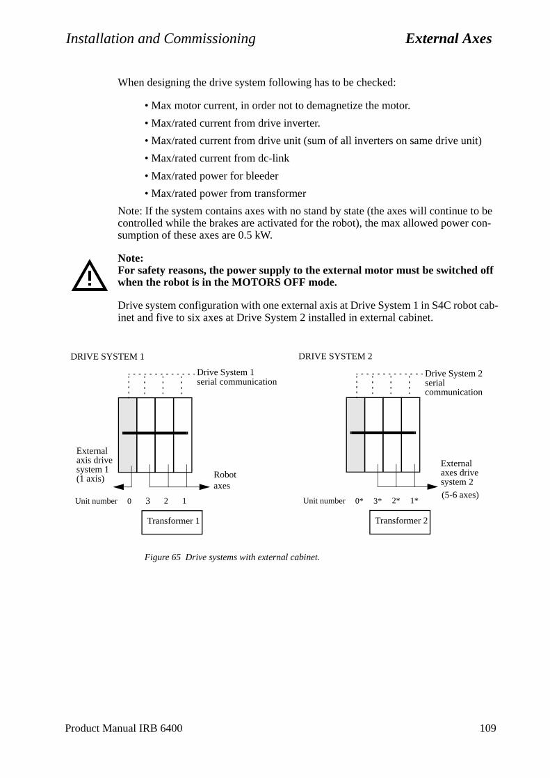
Installation and Commissioning External Axes
o be on-
cab-
When designing the drive system following has to be checked:
• Max motor current, in order not to demagnetize the motor.
• Max/rated current from drive inverter.
• Max/rated current from drive unit (sum of all inverters on same drive unit)
• Max/rated current from dc-link
• Max/rated power for bleeder
• Max/rated power from transformer
Note: If the system contains axes with no stand by state (the axes will continue tcontrolled while the brakes are activated for the robot), the max allowed power csumption of these axes are 0.5 kW.
Note:For safety reasons, the power supply to the external motor must be switched off when the robot is in the MOTORS OFF mode.
Drive system configuration with one external axis at Drive System 1 in S4C robotinet and five to six axes at Drive System 2 installed in external cabinet.
Figure 65 Drive systems with external cabinet.
0 3 2 1
Robotaxes
Unit number
Drive System 1serial communication
Transformer 1
DRIVE SYSTEM 1
0* 3* 2* 1*Unit number
Transformer 2
DRIVE SYSTEM 2
Drive System 2serial communication
(5-6 axes)
Externalaxis drivesystem 1(1 axis)
Externalaxes drivesystem 2
Product Manual IRB 6400 109
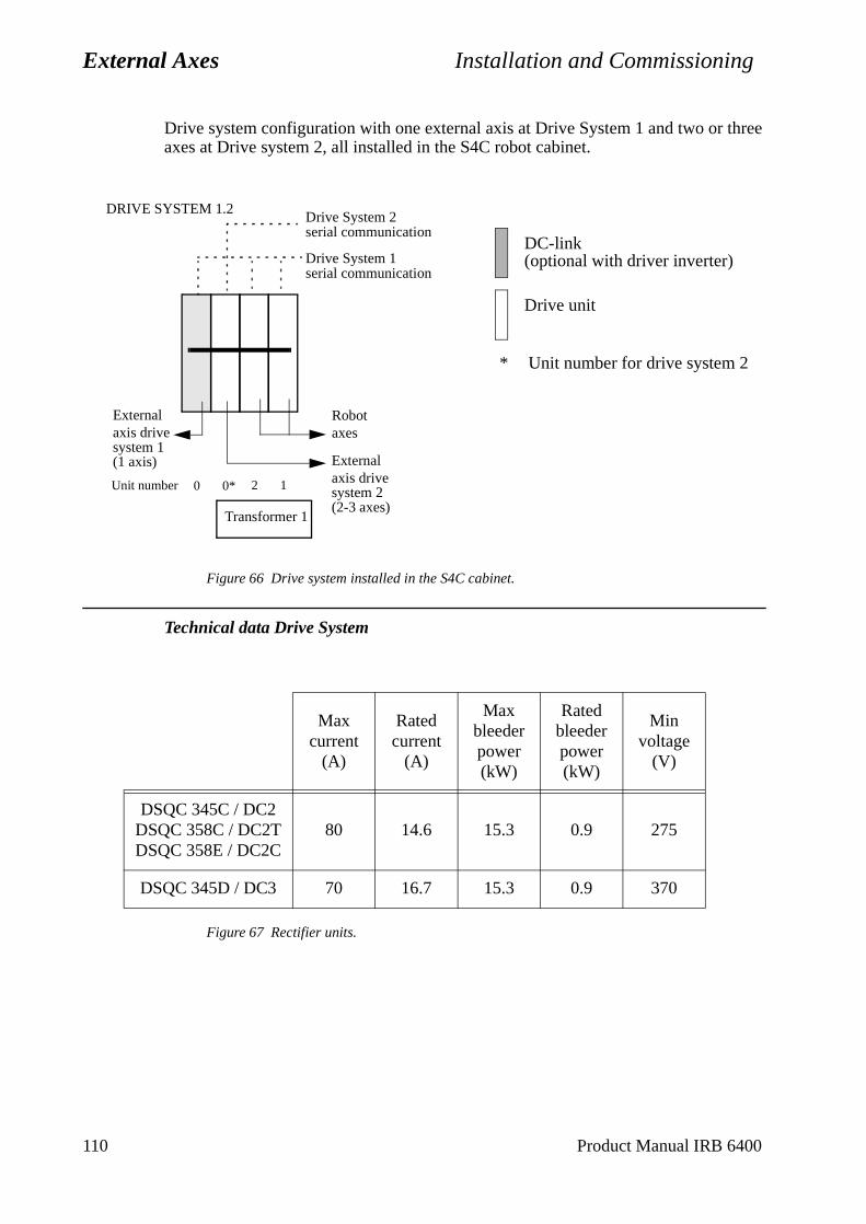
External Axes Installation and Commissioning
Drive system configuration with one external axis at Drive System 1 and two or three axes at Drive system 2, all installed in the S4C robot cabinet.
Figure 66 Drive system installed in the S4C cabinet.
Technical data Drive System
Figure 67 Rectifier units.
Max current
(A)
Rated current
(A)
Max bleeder power (kW)
Rated bleeder power (kW)
Min voltage
(V)
DSQC 345C / DC2DSQC 358C / DC2TDSQC 358E / DC2C
80 14.6 15.3 0.9 275
DSQC 345D / DC3 70 16.7 15.3 0.9 370
Externalaxis drivesystem 1
Externalaxis drivesystem 20 0* 2 1
Robotaxes
Unit number
Transformer 1
DRIVE SYSTEM 1.2Drive System 2serial communication
Drive System 1serial communication
DC-link(optional with driver inverter)
Drive unit
* Unit number for drive system 2
(1 axis)
(2-3 axes)
110 Product Manual IRB 6400
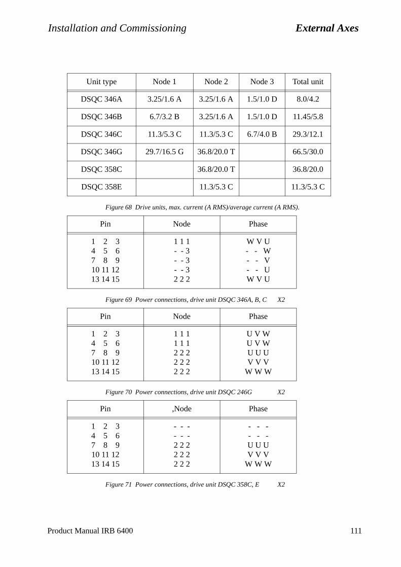
Installation and Commissioning External Axes
Figure 68 Drive units, max. current (A RMS)/average current (A RMS).
Figure 69 Power connections, drive unit DSQC 346A, B, C X2
Figure 70 Power connections, drive unit DSQC 246G X2
Figure 71 Power connections, drive unit DSQC 358C, E X2
Unit type Node 1 Node 2 Node 3 Total unit
DSQC 346A 3.25/1.6 A 3.25/1.6 A 1.5/1.0 D 8.0/4.2
DSQC 346B 6.7/3.2 B 3.25/1.6 A 1.5/1.0 D 11.45/5.8
DSQC 346C 11.3/5.3 C 11.3/5.3 C 6.7/4.0 B 29.3/12.1
DSQC 346G 29.7/16.5 G 36.8/20.0 T 66.5/30.0
DSQC 358C 36.8/20.0 T 36.8/20.0
DSQC 358E 11.3/5.3 C 11.3/5.3 C
Pin Node Phase
1 2 34 5 67 8 910 11 1213 14 15
1 1 1- - 3- - 3 - - 32 2 2
W V U- - W- - V- - UW V U
Pin Node Phase
1 2 34 5 67 8 910 11 1213 14 15
1 1 11 1 12 2 2 2 2 22 2 2
U V WU V WU U UV V V
W W W
Pin ,Node Phase
1 2 34 5 67 8 910 11 1213 14 15
- - -- - -2 2 2 2 2 22 2 2
- - - - - -U U UV V V
W W W
Product Manual IRB 6400 111
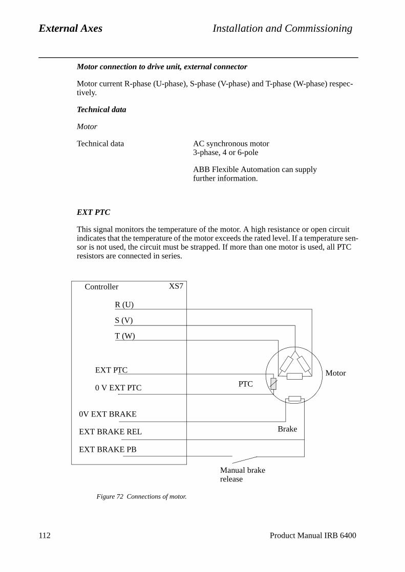
External Axes Installation and Commissioning
112 Product Manual IRB 6400
Motor connection to drive unit, external connector
Motor current R-phase (U-phase), S-phase (V-phase) and T-phase (W-phase) respec-tively.
Technical data
Motor
Technical data AC synchronous motor 3-phase, 4 or 6-pole
ABB Flexible Automation can supply further information.
EXT PTC
This signal monitors the temperature of the motor. A high resistance or open circuit indicates that the temperature of the motor exceeds the rated level. If a temperature sen-sor is not used, the circuit must be strapped. If more than one motor is used, all PTC resistors are connected in series.
Figure 72 Connections of motor.
Controller
R (U)
S (V)
T (W)
XS7
EXT PTC
0 V EXT PTC
MotorPTC
0V EXT BRAKE
EXT BRAKE REL
EXT BRAKE PB
Brake
Manual brake release
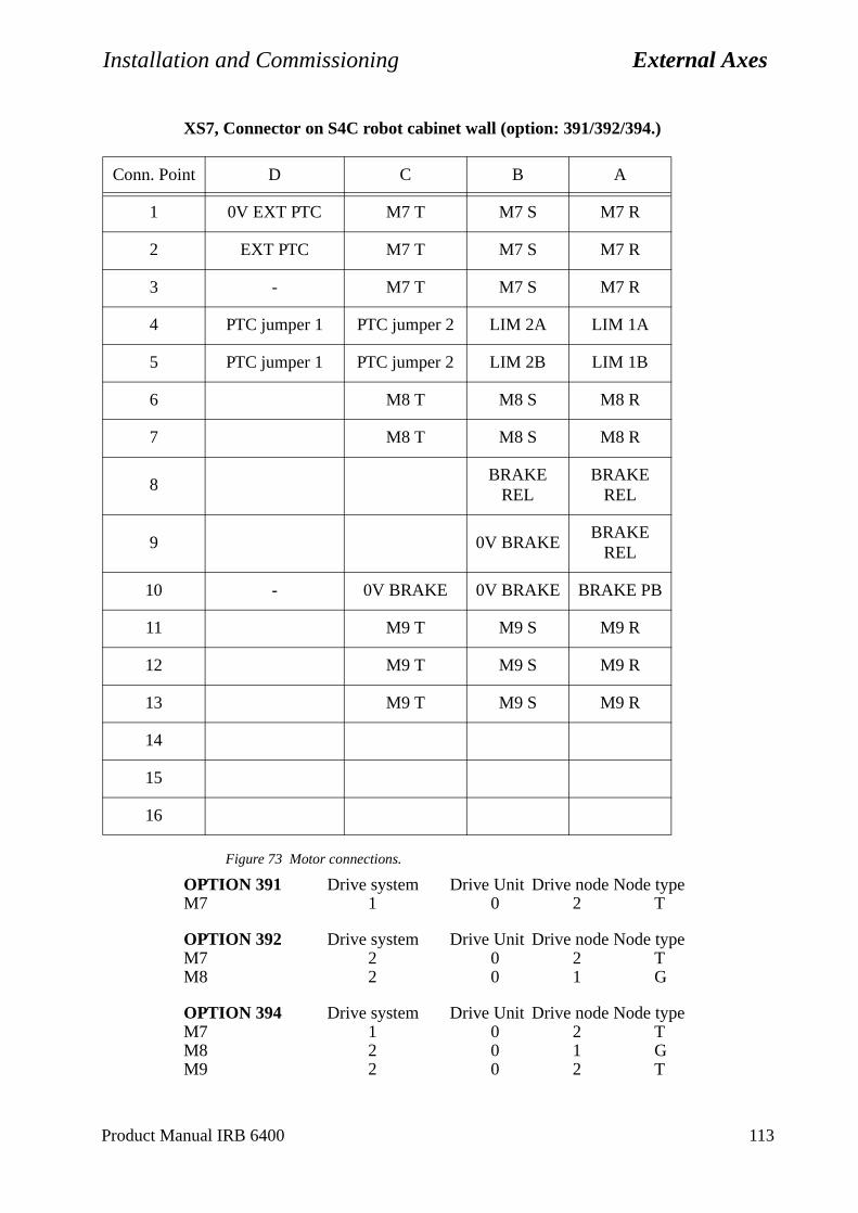
Installation and Commissioning External Axes
XS7, Connector on S4C robot cabinet wall (option: 391/392/394.)
Figure 73 Motor connections.
OPTION 391 Drive system Drive Unit Drive node Node typeM7 1 0 2 T
OPTION 392 Drive system Drive Unit Drive node Node typeM7 2 0 2 TM8 2 0 1 G
OPTION 394 Drive system Drive Unit Drive node Node typeM7 1 0 2 TM8 2 0 1 GM9 2 0 2 T
Conn. Point D C B A
1 0V EXT PTC M7 T M7 S M7 R
2 EXT PTC M7 T M7 S M7 R
3 - M7 T M7 S M7 R
4 PTC jumper 1 PTC jumper 2 LIM 2A LIM 1A
5 PTC jumper 1 PTC jumper 2 LIM 2B LIM 1B
6 M8 T M8 S M8 R
7 M8 T M8 S M8 R
8BRAKE
RELBRAKE
REL
9 0V BRAKEBRAKE
REL
10 - 0V BRAKE 0V BRAKE BRAKE PB
11 M9 T M9 S M9 R
12 M9 T M9 S M9 R
13 M9 T M9 S M9 R
14
15
16
Product Manual IRB 6400 113
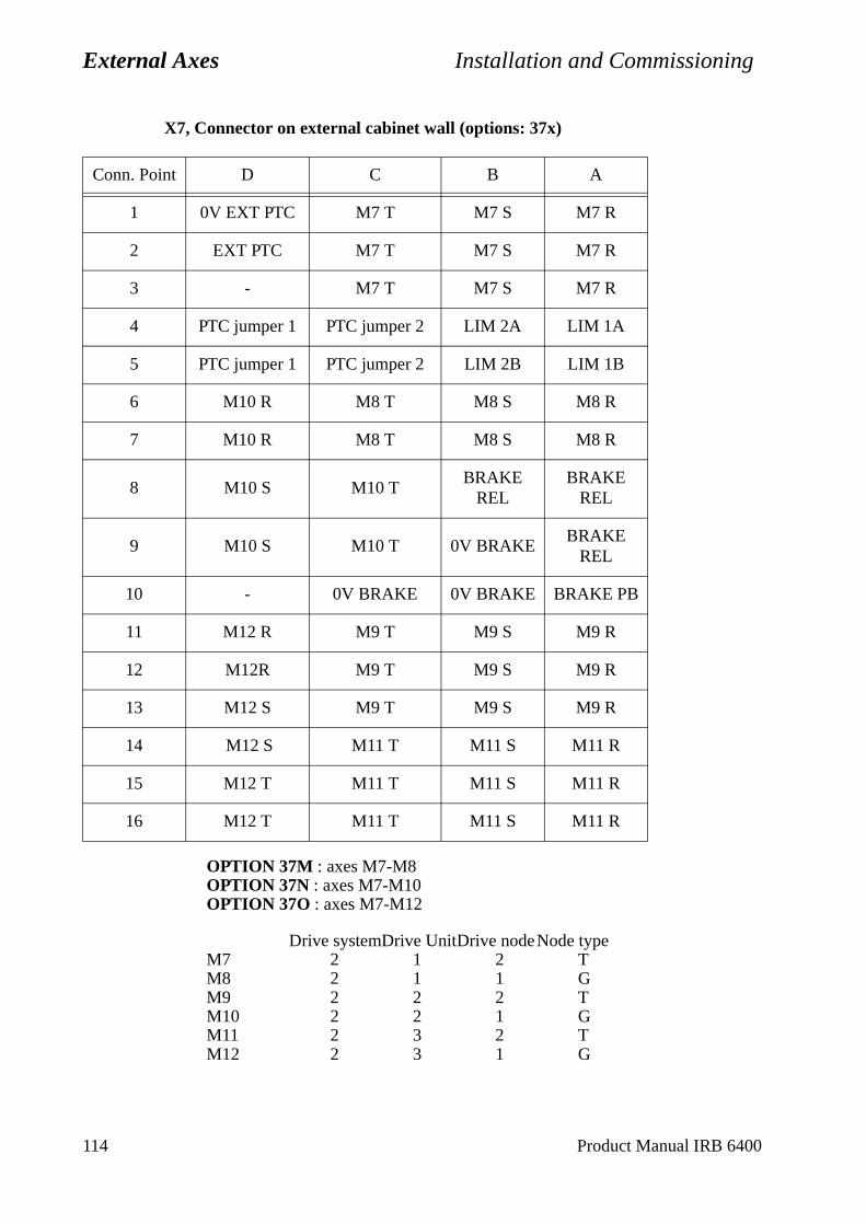
External Axes Installation and Commissioning
X7, Connector on external cabinet wall (options: 37x)
OPTION 37M : axes M7-M8OPTION 37N : axes M7-M10OPTION 37O : axes M7-M12
Drive systemDrive UnitDrive nodeNode typeM7 2 1 2 TM8 2 1 1 GM9 2 2 2 TM10 2 2 1 GM11 2 3 2 TM12 2 3 1 G
Conn. Point D C B A
1 0V EXT PTC M7 T M7 S M7 R
2 EXT PTC M7 T M7 S M7 R
3 - M7 T M7 S M7 R
4 PTC jumper 1 PTC jumper 2 LIM 2A LIM 1A
5 PTC jumper 1 PTC jumper 2 LIM 2B LIM 1B
6 M10 R M8 T M8 S M8 R
7 M10 R M8 T M8 S M8 R
8 M10 S M10 TBRAKE
RELBRAKE
REL
9 M10 S M10 T 0V BRAKEBRAKE
REL
10 - 0V BRAKE 0V BRAKE BRAKE PB
11 M12 R M9 T M9 S M9 R
12 M12R M9 T M9 S M9 R
13 M12 S M9 T M9 S M9 R
14 M12 S M11 T M11 S M11 R
15 M12 T M11 T M11 S M11 R
16 M12 T M11 T M11 S M11 R
114 Product Manual IRB 6400
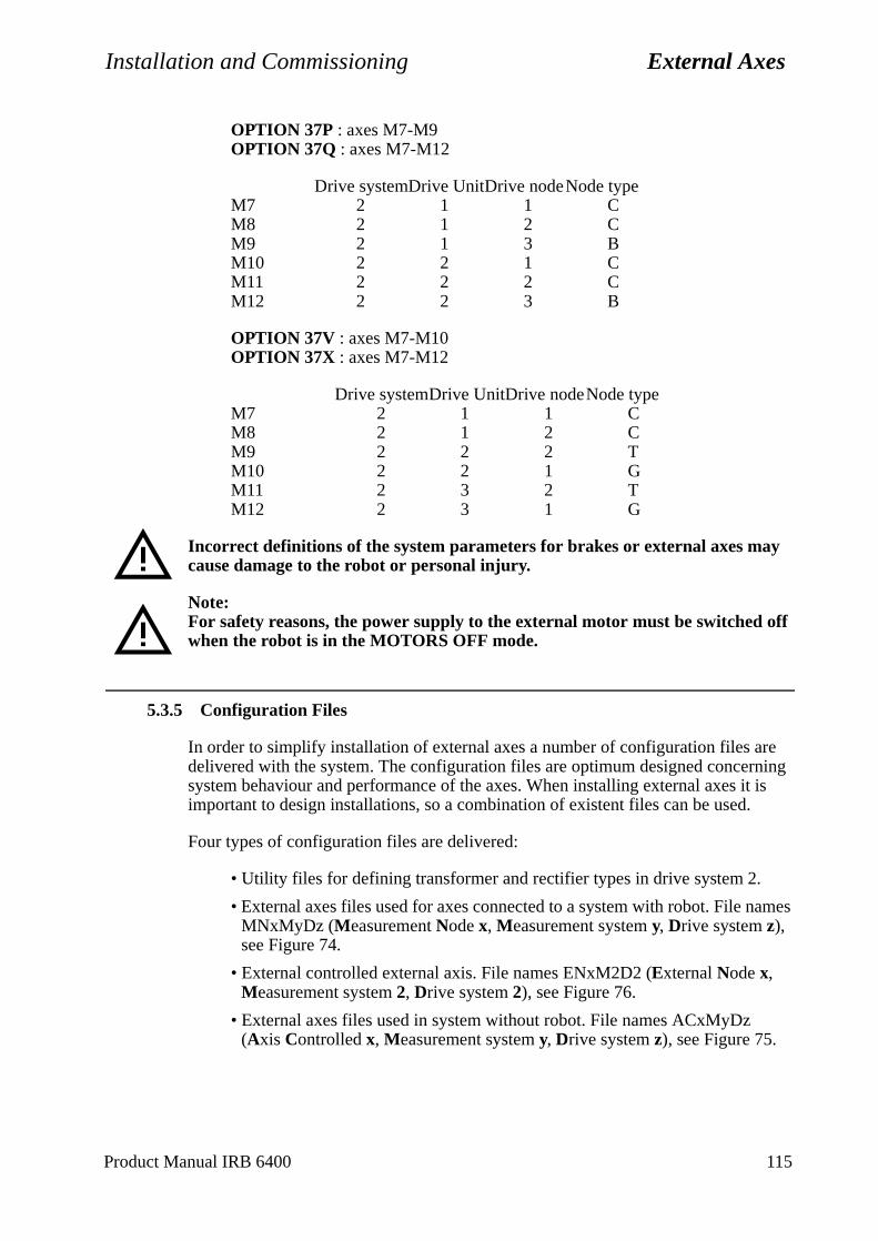
Installation and Commissioning External Axes
ames
OPTION 37P : axes M7-M9OPTION 37Q : axes M7-M12
Drive systemDrive UnitDrive nodeNode typeM7 2 1 1 CM8 2 1 2 CM9 2 1 3 BM10 2 2 1 CM11 2 2 2 CM12 2 2 3 B
OPTION 37V : axes M7-M10OPTION 37X : axes M7-M12
Drive systemDrive UnitDrive nodeNode typeM7 2 1 1 CM8 2 1 2 CM9 2 2 2 TM10 2 2 1 GM11 2 3 2 TM12 2 3 1 G
Incorrect definitions of the system parameters for brakes or external axes may cause damage to the robot or personal injury.
Note:For safety reasons, the power supply to the external motor must be switched off when the robot is in the MOTORS OFF mode.
5.3.5 Configuration Files
In order to simplify installation of external axes a number of configuration files are delivered with the system. The configuration files are optimum designed concerning system behaviour and performance of the axes. When installing external axes it is important to design installations, so a combination of existent files can be used.
Four types of configuration files are delivered:
• Utility files for defining transformer and rectifier types in drive system 2.
• External axes files used for axes connected to a system with robot. File nMNxMyDz (Measurement Node x, Measurement system y, Drive system z), see Figure 74.
• External controlled external axis. File names ENxM2D2 (External Node x, Measurement system 2, Drive system 2), see Figure 76.
• External axes files used in system without robot. File names ACxMyDz (Axis Controlled x, Measurement system y, Drive system z), see Figure 75.
Product Manual IRB 6400 115
External Axes Installation and Commissioning
arame-
teach
For installing and change of parameter data, see the User’s Guide, section System Pters, Topic: Manipulator.
In order to have the possibility to read and change most of the parameters from the pendent unit, the system must be booted in service mode.
116 Product Manual IRB 6400
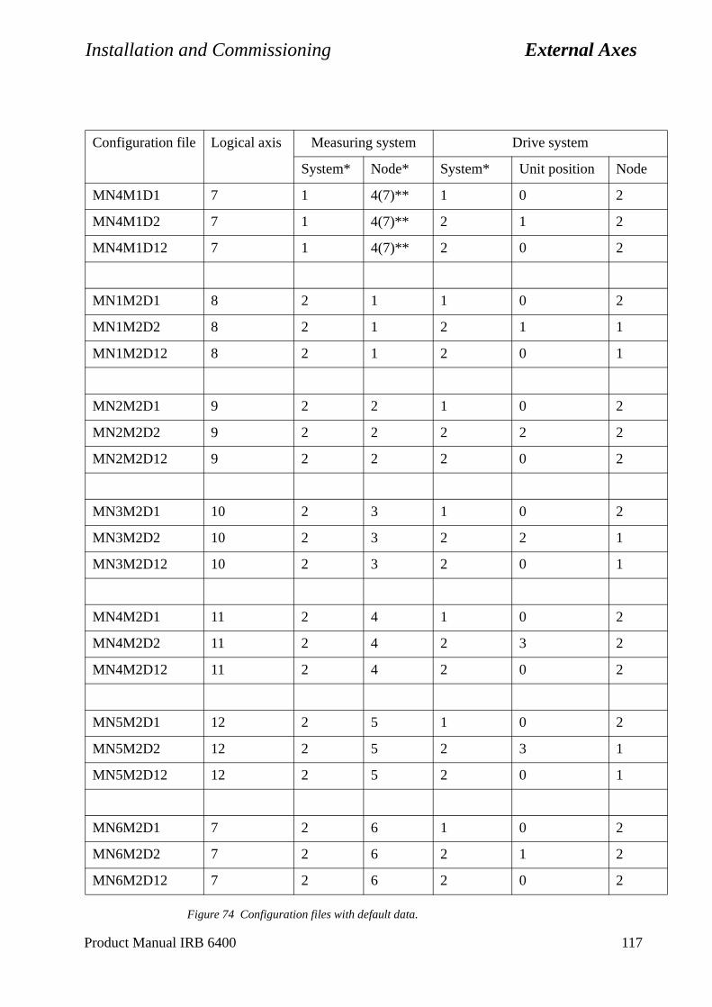
Installation and Commissioning External Axes
Figure 74 Configuration files with default data.
Configuration file Logical axis Measuring system Drive system
System* Node* System* Unit position Node
MN4M1D1 7 1 4(7)** 1 0 2
MN4M1D2 7 1 4(7)** 2 1 2
MN4M1D12 7 1 4(7)** 2 0 2
MN1M2D1 8 2 1 1 0 2
MN1M2D2 8 2 1 2 1 1
MN1M2D12 8 2 1 2 0 1
MN2M2D1 9 2 2 1 0 2
MN2M2D2 9 2 2 2 2 2
MN2M2D12 9 2 2 2 0 2
MN3M2D1 10 2 3 1 0 2
MN3M2D2 10 2 3 2 2 1
MN3M2D12 10 2 3 2 0 1
MN4M2D1 11 2 4 1 0 2
MN4M2D2 11 2 4 2 3 2
MN4M2D12 11 2 4 2 0 2
MN5M2D1 12 2 5 1 0 2
MN5M2D2 12 2 5 2 3 1
MN5M2D12 12 2 5 2 0 1
MN6M2D1 7 2 6 1 0 2
MN6M2D2 7 2 6 2 1 2
MN6M2D12 7 2 6 2 0 2
Product Manual IRB 6400 117
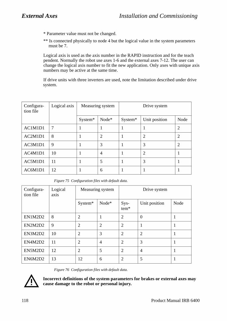
External Axes Installation and Commissioning
* Parameter value must not be changed.
** Is connected physically to node 4 but the logical value in the system parameters must be 7.
Logical axis is used as the axis number in the RAPID instruction and for the teach pendent. Normally the robot use axes 1-6 and the external axes 7-12. The user can change the logical axis number to fit the new application. Only axes with unique axis numbers may be active at the same time.
If drive units with three inverters are used, note the limitation described under drive system.
Figure 75 Configuration files with default data.
Figure 76 Configuration files with default data.
Incorrect definitions of the system parameters for brakes or external axes may cause damage to the robot or personal injury.
Configura-tion file
Logical axis Measuring system Drive system
System* Node* System* Unit position Node
AC1M1D1 7 1 1 1 1 2
AC2M1D1 8 1 2 1 2 2
AC3M1D1 9 1 3 1 3 2
AC4M1D1 10 1 4 1 2 1
AC5M1D1 11 1 5 1 3 1
AC6M1D1 12 1 6 1 1 1
Configura-tion file
Logical axis
Measuring system Drive system
System* Node* Sys-tem*
Unit position Node
EN1M2D2 8 2 1 2 0 1
EN2M2D2 9 2 2 2 1 1
EN3M2D2 10 2 3 2 2 1
EN4M2D2 11 2 4 2 3 1
EN5M2D2 12 2 5 2 4 1
EN6M2D2 13 12 6 2 5 1
118 Product Manual IRB 6400
Maintenance
CONTENTSPage
1 Maintenance Schedule............................................................................................. 4
1.1 Maintenance intervals for gear axes 1 and 6 for press-tending applications and heavy duty operation on axis 1 ................................................................ 5
1.2 Approx. estimate of operating life of base cable ............................................ 6
2 Instructions for Maintenance ................................................................................. 7
2.1 General instructions for the manipulator ........................................................ 7
2.2 Checking the oil and grease levels.................................................................. 7
2.3 Lubricating the large diameter bearing, axis 1................................................ 8
2.4 Lubricating gear box, axis 1............................................................................ 9
2.5 Inspect and lubricate the bearings, balancing units axis 2 .............................. 10
2.6 Lubricating piston rod, balancing unit axis 2.................................................. 11
2.7 Lubricating gearboxes, axes 2 and 3............................................................... 12
2.8 Oil change gearbox, axis 4.............................................................................. 13
2.9 Oil change gearbox, axis 5.............................................................................. 14
2.10 Lubricating gear box, axis 6.......................................................................... 15
2.11 Checking mechanical stop, axis 1 ................................................................. 16
2.12 Changing the battery in the measuring system ............................................. 17
2.13 Changing filter/cooling of motor axis 1........................................................ 18
2.14 Changing filters/vacuum cleaning the drive-system cooling........................ 19
2.15 Changing the battery for memory back-up ................................................... 19
2.16 RAM Battery lifetime ................................................................................... 20
Product Manual IRB 6400 1

Maintenance
CONTENTSPage
2 Product Manual IRB 6400
Maintenance
ner or e
are ver, uum nce
t and
Maintenance
The robot is designed to be able to work under very demanding conditions with a minimum of maintenance. Nevertheless, certain routine checks and preventative maintenance must be carried out at specified periodic intervals, as shown in the table below.
• The exterior of the robot should be cleaned as required. Use a vacuum cleawipe it with a cloth. Compressed air and harsh solvents that can damage thsealing joints, bearings, lacquer or cabling, must not be used.
• The control system is completely encased, which means that the electronicsprotected in a normal working environment. In very dusty environments, howethe interior of the cabinet should be inspected at regular intervals. Use a vaccleaner if necessary. Change filters in accordance with prescribed maintenaprocedures.
• Check that the sealing joints and cable glands are really airtight so that dusdirt are not sucked into the cabinet.
Product Manual IRB 6400 3

Maintenance
.
4 Product Manual IRB 6400
1 Maintenance Schedule
Prescribed maintenance
Maintenance intervals
Checktwice a
year
Checkonce a year
4 000 hor
2 years
12 000 h or
3 years 5 years
MANIPULATORBalancing unit axis 2Bearings, inspection
X
Balancing unit axis 2Bearings, greasing
X1
1. For foundry operation.
X
Balancing unit axis 2Piston rod/Guiding ring
X2
2. If the robot operation is utilized in adverse conditions (for example: particle-laden environments, such as spot welding, grinding, deflashing, etc.), perform preventive maintenance more frequently to ensure proper reliability of the robot system. See section 2.6.
Large diameter bearingGreasing
X3
3. For foundry operation and recommended interval for large movements ≥ ±45° on axis 1.
X
Cabling X4
4. Inspect all visible cabling. Change if damaged. See section 1.2.
Mechanical stop axis 1 X5
5. Check the mechanical stop devices for deformation and damage. If the stop pin or the adjustable stop arm is bent, it must be replaced. See section 2.11.
Gearboxes 1, 6 Grease changing
X6
6. For press-tending (refers to grease changing and operating life for gearboxes 1 and 6) and heavy dutyoperation, axis 1 (option 5x is installed).
Gearboxes 1, 2, 3 and 6Grease changing
X
Oil level in gearboxes 4 and 5 X
Gearboxes 4 and 5Oil changing
X
Accumulator for measuring systemExchange
3 years7
7. See section 2.12.
Cooling motor, axis 1Filter changing
X8
8. Change interval is strongly dependent on the environment around the robot. See section 2.13 and 2.14
X
CONTROLSYSTEM
Filter for drive-system cooling X8 X
Memory back-upBattery changing
X9
9. See section 2.16.
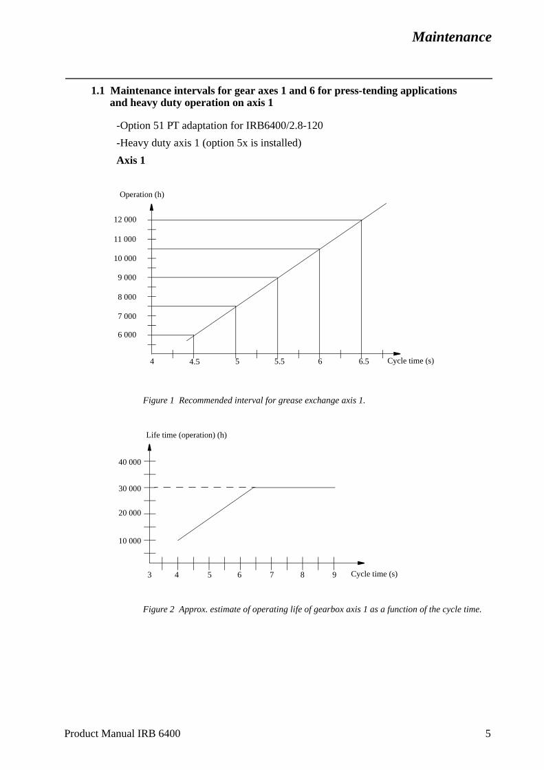
Maintenance
1.1 Maintenance intervals for gear axes 1 and 6 for press-tending applications and heavy duty operation on axis 1
-Option 51 PT adaptation for IRB6400/2.8-120
-Heavy duty axis 1 (option 5x is installed)
Axis 1
Figure 1 Recommended interval for grease exchange axis 1.
Figure 2 Approx. estimate of operating life of gearbox axis 1 as a function of the cycle time.
12 000
7 000
9 000
10 000
11 000
6 000
8 000
4 5 5.5 6 6.5 Cycle time (s)4.5
Operation (h)
Cycle time (s)
Life time (operation) (h)
40 000
30 000
20 000
10 000
3 4 5 6 7 8 9
Product Manual IRB 6400 5

Maintenance
6 Product Manual IRB 6400
Axis 6
Figure 3 Recommended interval for grease exchange axis 6
Figure 4 Approx. estimate of operating life of gearbox axis 6 as a function of the moment of inertia Ja6. Ja6 according to the Product Specification, chapter 3.
1.2 Approx. estimate of operating life of base cable
Approx. estimate of operating life of base cable is 4 million cycles.
12 000
11 000
10 000
9 000
8 000
7 000
6 000
5 000
4 000
50 100 120
Operation (h)
Moment of inertia Ja6 (kgm2)
Moment of inertia Ja6 (kgm2)50 100 120
40 000
30 000
20 000
10 000
Life time (operation) (h)
Maintenance
lvents
s out 2 and
box,
2 Instructions for Maintenance
2.1 General instructions for the manipulator
Check regularly:
• for any oil leaks. If a major oil leak is discovered, call for service personnel.
• for excessive play in gears. If play develops, call for service personnel.
• that the cabling between the control cabinet and robot is not damaged.
Cleaning:
• Clean the robot exterior with a cloth when necessary. Do not use aggressive sowhich may damage paint or cabling.
2.2 Checking the oil and grease levels
Axes 1, 2, 3 and 6
The level in the gearboxes is checked by adding new grease, until grease comethrough the special draining holes. See Chapter 2.7, Lubricating gearboxes, axes3 and Chapter 2.10, Lubricating gear box, axis 6.
Axes 4 and 5
The level is checked by opening the oil plugs. See Chapter 2.8, Oil change gearaxis 4 and Chapter 2.9, Oil change gearbox, axis 5.
Product Manual IRB 6400 7
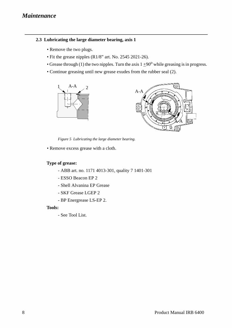
Maintenance
.
2.3 Lubricating the large diameter bearing, axis 1
• Remove the two plugs.
• Fit the grease nipples (R1/8” art. No. 2545 2021-26).
• Grease through (1) the two nipples. Turn the axis 1 +90o while greasing is in progress
• Continue greasing until new grease exudes from the rubber seal (2).
Figure 5 Lubricating the large diameter bearing.
• Remove excess grease with a cloth.
Type of grease:
- ABB art. no. 1171 4013-301, quality 7 1401-301
- ESSO Beacon EP 2
- Shell Alvanina EP Grease
- SKF Grease LGEP 2
- BP Energrease LS-EP 2.
Tools:
- See Tool List.
A-A1 2
A-A
A-A
8 Product Manual IRB 6400
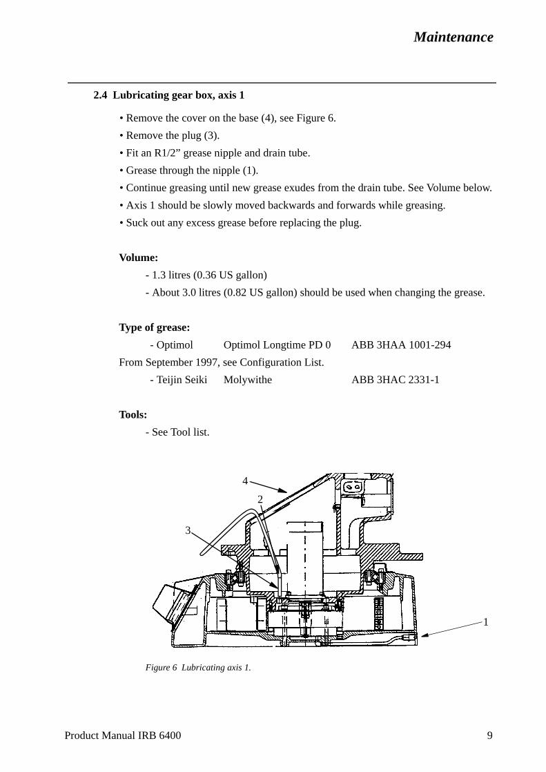
Maintenance
elow.
se.
Product Manual IRB 6400 9
2.4 Lubricating gear box, axis 1
• Remove the cover on the base (4), see Figure 6.
• Remove the plug (3).
• Fit an R1/2” grease nipple and drain tube.
• Grease through the nipple (1).
• Continue greasing until new grease exudes from the drain tube. See Volume b
• Axis 1 should be slowly moved backwards and forwards while greasing.
• Suck out any excess grease before replacing the plug.
Volume:
- 1.3 litres (0.36 US gallon)
- About 3.0 litres (0.82 US gallon) should be used when changing the grea
Type of grease:
- Optimol Optimol Longtime PD 0 ABB 3HAA 1001-294
From September 1997, see Configuration List.
- Teijin Seiki Molywithe ABB 3HAC 2331-1
Tools:
- See Tool list.
Figure 6 Lubricating axis 1.
2
1
3
4
Maintenance
10 Product Manual IRB 6400
2.5 Inspect and lubricate the bearings, balancing units axis 2
The bearings should be inspected and lubricated every 12 000 hours.
1. Move axis 2 to the sync position.
Make sure the shaft between the upper and lower arms does not rotate when unscrewing the KM nut.
2. Remove the KM- nuts (KM-8), the outer support washers and sealing rings.
Inspect
3. Fit the auxiliary shafts on the upper and lower axes (upper: aux. shaft3HAB 6558-1, lower: aux. shaft 3HAB 6567-1). The shafts should be tightened totheir bottom position.
4. Off-load the bearings using an M10x50 screw at the cylinder top.
5. Put out the cylinder so that the inner rings are fully exposed. Wipe the inner rings clean and check that there are no pressure marks or other similar deformations. It is quite normal for the bearing races to have a darker colour than the surroundingmaterial.
6. Inspect the support washers and sealing rings.
7. Push in the cylinder, make sure the inner support washers and sealing rings gets incorrect position.
8. Remove the auxiliary shafts.
Lubrication
8. Fit the lubricating tool 3HAC 4701-1. The tool should be tightened to the bottomposition only by hand power.
9. Grease through the nipple. Continue greasing until the grease exudes behind theinner sealing ring. Repeat procedure for the other bearings.
10. Remove the lubricating tool and clean the threads on the shaft ends free fromgrease.
11. Remount the outer sealing rings, apply some grease on the support washers, applyLoctite 243 on the KM nuts, not on the shafts, and tighten them to a torque of 50-60 Nm.
12. Check play (min 0.1 mm) between support washer and bearingseat at both bearings.
13. N.B. Remove the M10x50 screw.
For more information about the procedure of replacing bearings, see Repairs.
Maintenance
Type of grease
- ABB art no. 1171 4013-301, quality 7 1401-301.
- ESSO Beacon EP 2.
- Shell Alvanina EP Grease.
- SKF Grease LGEP 2.
- BP Energrease LS-EP2.
Type of grease to Foundry robots
- - Shell Retinax MS
2.6 Lubricating piston rod, balancing unit axis 2
Move axis 2 to a position where the balancing units are in the horizontal position.
Wear
Check the guiding ring for wear. If there is a risk of metallic contact between the piston rod and the end cover, the guiding ring must be replaced. For replacement, see Repairs.
The article number of the guiding ring is 3HAB 6176-1.
Lubrication
The piston rods should be lubricated. Clean the piston rod and apply new grease when necessary.
Type of grease
- Castrol Spheerol SX2 or equivalent.
- Shell Grease 1352 CA EP2.
- OK Super Grease L2.
- Statoil Uniway 2X2N.
Product Manual IRB 6400 11
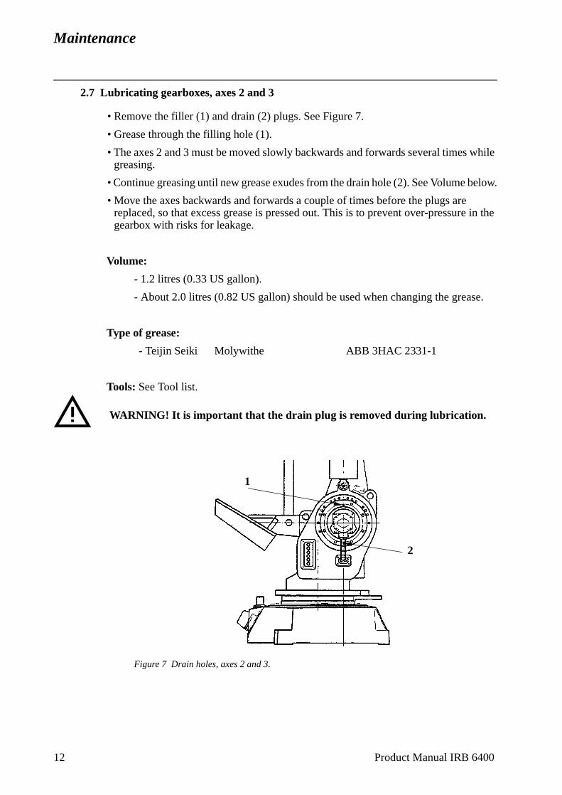
Maintenance
while
below.
e in the
se.
2.7 Lubricating gearboxes, axes 2 and 3
• Remove the filler (1) and drain (2) plugs. See Figure 7.
• Grease through the filling hole (1).
• The axes 2 and 3 must be moved slowly backwards and forwards several timesgreasing.
• Continue greasing until new grease exudes from the drain hole (2). See Volume
• Move the axes backwards and forwards a couple of times before the plugs arereplaced, so that excess grease is pressed out. This is to prevent over-pressurgearbox with risks for leakage.
Volume:
- 1.2 litres (0.33 US gallon).
- About 2.0 litres (0.82 US gallon) should be used when changing the grea
Type of grease:
- Teijin Seiki Molywithe ABB 3HAC 2331-1
Tools: See Tool list.
Figure 7 Drain holes, axes 2 and 3.
WARNING! It is important that the drain plug is removed during lubrication.
1
2
12 Product Manual IRB 6400
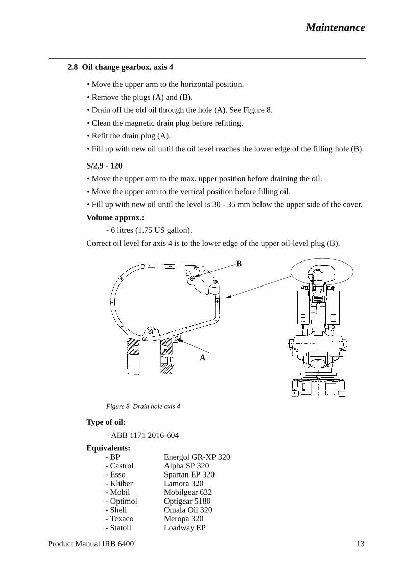
Maintenance
).
er.
Product Manual IRB 6400 13
2.8 Oil change gearbox, axis 4
• Move the upper arm to the horizontal position.
• Remove the plugs (A) and (B).
• Drain off the old oil through the hole (A). See Figure 8.
• Clean the magnetic drain plug before refitting.
• Refit the drain plug (A).
• Fill up with new oil until the oil level reaches the lower edge of the filling hole (B
S/2.9 - 120
• Move the upper arm to the max. upper position before draining the oil.
• Move the upper arm to the vertical position before filling oil.
• Fill up with new oil until the level is 30 - 35 mm below the upper side of the cov
Volume approx.:
- 6 litres (1.75 US gallon).
Correct oil level for axis 4 is to the lower edge of the upper oil-level plug (B).
Figure 8 Drain hole axis 4
Type of oil:
- ABB 1171 2016-604
Equivalents:- BP Energol GR-XP 320- Castrol Alpha SP 320- Esso Spartan EP 320- Klüber Lamora 320- Mobil Mobilgear 632- Optimol Optigear 5180- Shell Omala Oil 320- Texaco Meropa 320- Statoil Loadway EP
A
B
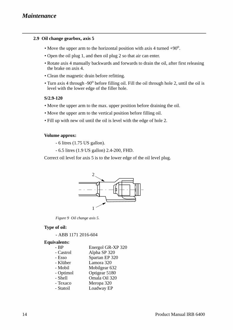
Maintenance
sing
2.9 Oil change gearbox, axis 5
• Move the upper arm to the horizontal position with axis 4 turned +90o.
• Open the oil plug 1, and then oil plug 2 so that air can enter.
• Rotate axis 4 manually backwards and forwards to drain the oil, after first releathe brake on axis 4.
• Clean the magnetic drain before refitting.
• Turn axis 4 through -90o before filling oil. Fill the oil through hole 2, until the oil islevel with the lower edge of the filler hole.
S/2.9-120
• Move the upper arm to the max. upper position before draining the oil.
• Move the upper arm to the vertical position before filling oil.
• Fill up with new oil until the oil is level with the edge of hole 2.
Volume approx:
- 6 litres (1.75 US gallon).
- 6.5 litres (1.9 US gallon) 2.4-200, FHD.
Correct oil level for axis 5 is to the lower edge of the oil level plug.
Figure 9 Oil change axis 5.
Type of oil:
- ABB 1171 2016-604
Equivalents:- BP Energol GR-XP 320- Castrol Alpha SP 320- Esso Spartan EP 320- Klüber Lamora 320- Mobil Mobilgear 632- Optimol Optigear 5180- Shell Omala Oil 320- Texaco Meropa 320- Statoil Loadway EP
2
1
14 Product Manual IRB 6400
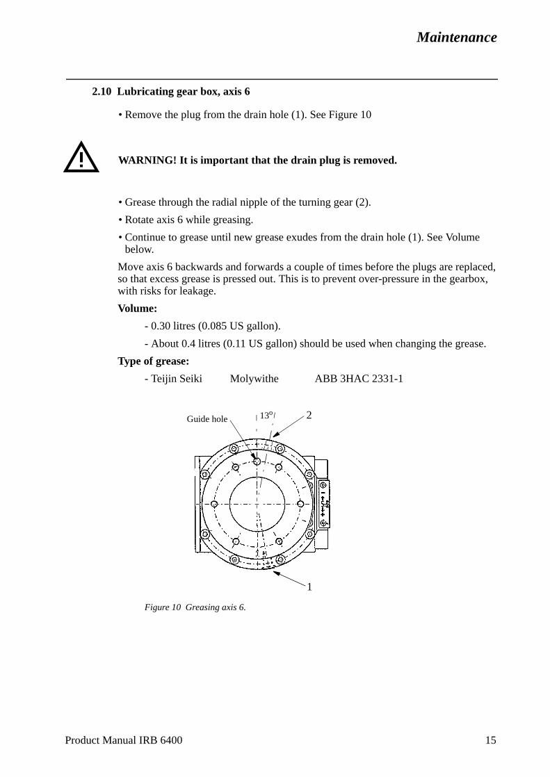
Maintenance
e
laced, rbox,
se.
Product Manual IRB 6400 15
2.10 Lubricating gear box, axis 6
• Remove the plug from the drain hole (1). See Figure 10
• Grease through the radial nipple of the turning gear (2).
• Rotate axis 6 while greasing.
• Continue to grease until new grease exudes from the drain hole (1). See Volumbelow.
Move axis 6 backwards and forwards a couple of times before the plugs are repso that excess grease is pressed out. This is to prevent over-pressure in the geawith risks for leakage.
Volume:
- 0.30 litres (0.085 US gallon).
- About 0.4 litres (0.11 US gallon) should be used when changing the grea
Type of grease:
- Teijin Seiki Molywithe ABB 3HAC 2331-1
Figure 10 Greasing axis 6.
WARNING! It is important that the drain plug is removed.
1
Guide hole 13o 2
Maintenance
2.11 Checking mechanical stop, axis 1
Check regularly, as follows:
Fixed stop arm:
- that the arm is not bent.
Stop pin:
- that the rubber cover is not damaged
- that the stop pin can move in both directions
- that the stop pin is not bent.
Adjustable stop arms:
- that the arms are not bent.
WARNING!
1. If the fixed stop arm is bent, no attempt must be made to straightened it.
2. If the pin is bent, a collision between the swinging stop arm and the stop pin has probably occurred. A bent stop pin must always be replaced by a new one.
3. If any of the adjustable stop arms are bent, they must be replaced by new ones.
Article number
Stop pin 3HAB 4082-1
Adjustable stop arm 3HAB 4533-3 (Option)
16 Product Manual IRB 6400
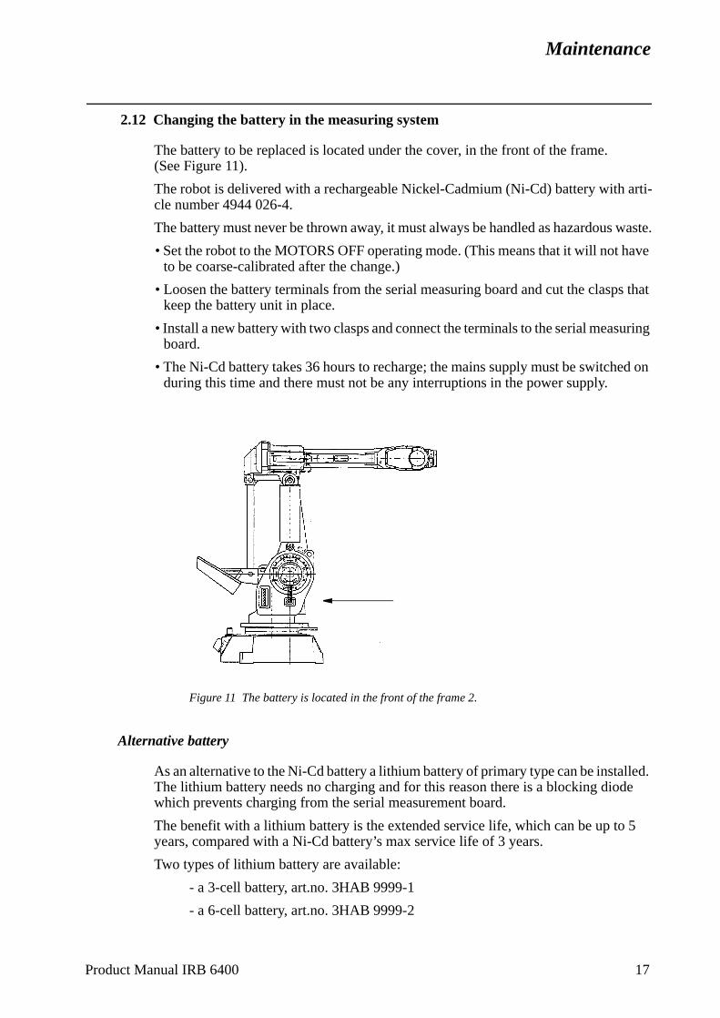
Maintenance
have
s that
uring
ed on
lled. de
5
2.12 Changing the battery in the measuring system
The battery to be replaced is located under the cover, in the front of the frame. (See Figure 11).
The robot is delivered with a rechargeable Nickel-Cadmium (Ni-Cd) battery with arti-cle number 4944 026-4.
The battery must never be thrown away, it must always be handled as hazardous waste.
• Set the robot to the MOTORS OFF operating mode. (This means that it will not to be coarse-calibrated after the change.)
• Loosen the battery terminals from the serial measuring board and cut the claspkeep the battery unit in place.
• Install a new battery with two clasps and connect the terminals to the serial measboard.
• The Ni-Cd battery takes 36 hours to recharge; the mains supply must be switchduring this time and there must not be any interruptions in the power supply.
Figure 11 The battery is located in the front of the frame 2.
Alternative battery
As an alternative to the Ni-Cd battery a lithium battery of primary type can be instaThe lithium battery needs no charging and for this reason there is a blocking diowhich prevents charging from the serial measurement board.
The benefit with a lithium battery is the extended service life, which can be up toyears, compared with a Ni-Cd battery’s max service life of 3 years.
Two types of lithium battery are available:
- a 3-cell battery, art.no. 3HAB 9999-1
- a 6-cell battery, art.no. 3HAB 9999-2
Product Manual IRB 6400 17
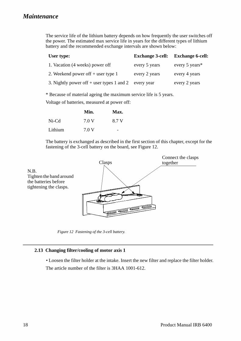
Maintenance
lder.
The service life of the lithium battery depends on how frequently the user switches off the power. The estimated max service life in years for the different types of lithium battery and the recommended exchange intervals are shown below:
* Because of material ageing the maximum service life is 5 years.
Voltage of batteries, measured at power off:
The battery is exchanged as described in the first section of this chapter, except for the fastening of the 3-cell battery on the board, see Figure 12.
Figure 12 Fastening of the 3-cell battery.
2.13 Changing filter/cooling of motor axis 1
• Loosen the filter holder at the intake. Insert the new filter and replace the filter ho
The article number of the filter is 3HAA 1001-612.
User type: Exchange 3-cell: Exchange 6-cell:
1. Vacation (4 weeks) power off every 5 years every 5 years*
2. Weekend power off + user type 1 every 2 years every 4 years
3. Nightly power off + user types 1 and 2 every year every 2 years
Min. Max.
Ni-Cd 7.0 V 8.7 V
Lithium 7.0 V -
ClaspsConnect the clasps together
N.B.Tighten the band around the batteries before tightening the clasps.
18 Product Manual IRB 6400
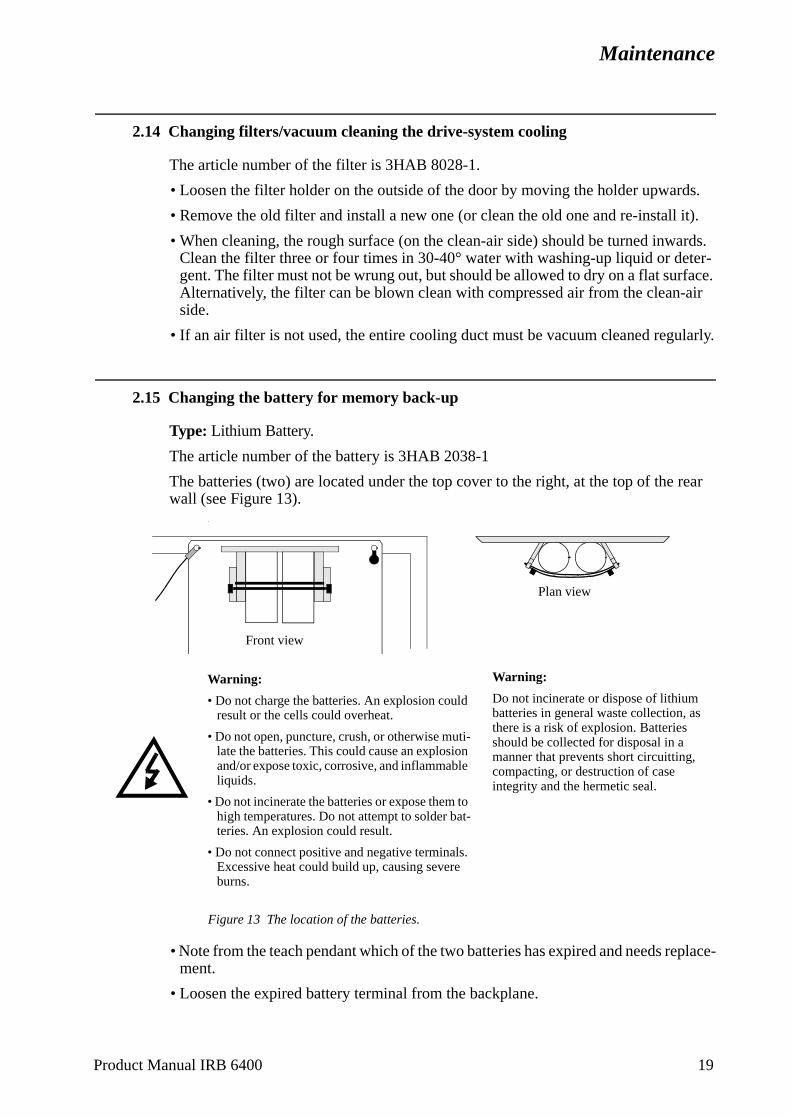
Maintenance
s.
it).
rds. ter-face. air
larly.
rear
place-
2.14 Changing filters/vacuum cleaning the drive-system cooling
The article number of the filter is 3HAB 8028-1.
• Loosen the filter holder on the outside of the door by moving the holder upward
• Remove the old filter and install a new one (or clean the old one and re-install
• When cleaning, the rough surface (on the clean-air side) should be turned inwaClean the filter three or four times in 30-40° water with washing-up liquid or degent. The filter must not be wrung out, but should be allowed to dry on a flat surAlternatively, the filter can be blown clean with compressed air from the clean-side.
• If an air filter is not used, the entire cooling duct must be vacuum cleaned regu
2.15 Changing the battery for memory back-up
Type: Lithium Battery.
The article number of the battery is 3HAB 2038-1
The batteries (two) are located under the top cover to the right, at the top of the wall (see Figure 13).
.
Figure 13 The location of the batteries.
• Note from the teach pendant which of the two batteries has expired and needs rement.
• Loosen the expired battery terminal from the backplane.
Front view
Plan view
Warning:
• Do not charge the batteries. An explosion could result or the cells could overheat.
• Do not open, puncture, crush, or otherwise muti-late the batteries. This could cause an explosion and/or expose toxic, corrosive, and inflammable liquids.
• Do not incinerate the batteries or expose them to high temperatures. Do not attempt to solder bat-teries. An explosion could result.
• Do not connect positive and negative terminals. Excessive heat could build up, causing severe burns.
Warning:
Do not incinerate or dispose of lithium batteries in general waste collection, as there is a risk of explosion. Batteries should be collected for disposal in a manner that prevents short circuitting, compacting, or destruction of case integrity and the hermetic seal.
Product Manual IRB 6400 19

Maintenance
e, all and
ced ut
eld
f the
y:
• Remove the battery by loosening the clasps.
• Insert the new battery and fasten the clasps.
• Connect the battery terminal to the backplane.
• If both batteries must be replaced, make sure that the power is kept on. Otherwisthe memory contents will be erased. A completely new installation of Robot Wareparameters is then necessary, see Installation and Commissioning.
2.16 RAM Battery lifetime
The maximum service life of the lithium battery is five years. The lifetime is influenby the installed memory board type and by the length of time the system is withopower.
The following table indicates the minimum time, in months, that memory will be hif the system is without power:
A battery test is performed during the following occasions:
1. System diagnistics (before softeware installation). Failing test results in one ofollowing messages on the display:
- “Warning: Battery 1 or 2 < 3.3V” i.e. one of the batteries is empty.
- “Error: Battery 1 and 2 < 3.3V” i.e. both batteries are empty.
2. Warm start. Failing test results in one of the following messages on the displa
- 31501 Battery voltage too low on battery 1.
- 31502 Battery voltage too low on battery 2.
- 31503 Battery voltage too low on both batteries.
Memory board size First battery Both batteries
4 MB 6 12
6 MB 5 10
8 MB 6.5 13
16 MB 5 10
20 Product Manual IRB 6400
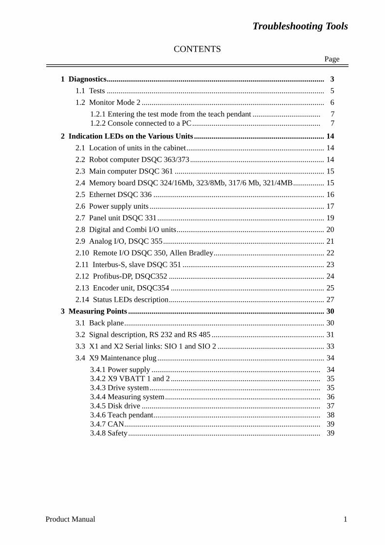
Troubleshooting Tools
CONTENTSPage
1 Diagnostics................................................................................................................ 3
1.1 Tests ................................................................................................................ 5
1.2 Monitor Mode 2 .............................................................................................. 6
1.2.1 Entering the test mode from the teach pendant ................................... 71.2.2 Console connected to a PC.................................................................. 7
2 Indication LEDs on the Various Units ................................................................... 14
2.1 Location of units in the cabinet....................................................................... 14
2.2 Robot computer DSQC 363/373..................................................................... 14
2.3 Main computer DSQC 361 ............................................................................. 15
2.4 Memory board DSQC 324/16Mb, 323/8Mb, 317/6 Mb, 321/4MB................ 15
2.5 Ethernet DSQC 336 ........................................................................................ 16
2.6 Power supply units .......................................................................................... 17
2.7 Panel unit DSQC 331...................................................................................... 19
2.8 Digital and Combi I/O units............................................................................ 20
2.9 Analog I/O, DSQC 355................................................................................... 21
2.10 Remote I/O DSQC 350, Allen Bradley......................................................... 22
2.11 Interbus-S, slave DSQC 351 ......................................................................... 23
2.12 Profibus-DP, DSQC352 ................................................................................ 24
2.13 Encoder unit, DSQC354 ............................................................................... 25
2.14 Status LEDs description................................................................................ 27
3 Measuring Points ..................................................................................................... 30
3.1 Back plane....................................................................................................... 30
3.2 Signal description, RS 232 and RS 485 .......................................................... 31
3.3 X1 and X2 Serial links: SIO 1 and SIO 2 ....................................................... 33
3.4 X9 Maintenance plug ...................................................................................... 34
3.4.1 Power supply ....................................................................................... 343.4.2 X9 VBATT 1 and 2 ............................................................................. 353.4.3 Drive system........................................................................................ 353.4.4 Measuring system................................................................................ 363.4.5 Disk drive ............................................................................................ 373.4.6 Teach pendant...................................................................................... 383.4.7 CAN..................................................................................................... 393.4.8 Safety................................................................................................... 39
Product Manual 1

Troubleshooting Tools
CONTENTSPage
2 Product Manual

Troubleshooting Tools
ic is e
ing plain
ast 50 lysed. g nor-ssages
e diag-
hen ted.
the ant. If sting tect
e user on the
nly a d on the
ack-t are
Troubleshooting Tools
Generally speaking, troubleshooting should be carried out as follows:
• Read any error messages shown on the teach pendant display.What these messages mean is described in System and Error Messages.
• Check the LEDs on the units. See Indication LEDs on the Various Units page 14.
• Switch the power off and then on. When the robot is started up, a self diagnostrun which detects any errors. The tests performed during the self diagnostic ardescribed in the chapter Diagnostics page 3.
• Check the cables, etc., with the help of the circuit diagram.
1 Diagnostics
The control system is supplied with diagnostic software to facilitate troubleshootand to reduce downtime. Any errors detected by the diagnostics are displayed inlanguage with an code number on the display of the teach pendant.
All system and error messages are logged in a common log which contains the lmessages saved. This enables an “error audit trail” to be made which can be anaThe log can be accessed from the Service window using the teach pendant durinmal operation and can be used to read or delete the logs. All system and error meavailable are listed in User’s Guide.
The diagnostic programs are stored in flash PROM on the robot computer board. Thnostic programs are executed by the I/O computer.
The control system runs through various tests depending on the start up mode:
Cold Start - Cold starts occur normally only when the control system is started the first time, or wany computer board has been replaced, or when the batteries have been disconnec
First, the test programs are executed by the robot computer (I/O computer) and main computer. These tests and the test results are displayed on the teach pendthe tests do not indicate any errors, a message will appear on the display, requeyou to insert a system diskette into the disk drive. If, however, the diagnostics dean error, a message will appear on the display and the test will be stopped until thhits a key on the teach pendant or on a terminal connected to the front connectorrobot computer.
Warm Start -is the normal type of start up when the robot is powered on. During a warm start, osubset of the test program is executed. These tests and the test results are displayeteach pendant.
Another type of warm start, INIT, is carried out via a push button located on the bplane (see section 3). INIT is very similar to switching the power on. The tests tharun depend on whether or not the system is booted.
Product Manual 3
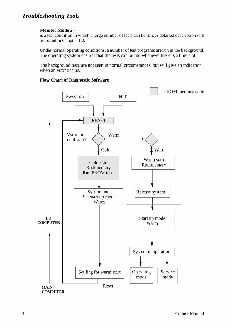
Troubleshooting Tools
Monitor Mode 2 -is a test condition in which a large number of tests can be run. A detailed description will be found in Chapter 1.2.
Under normal operating conditions, a number of test programs are run in the background. The operating system ensures that the tests can be run whenever there is a time slot.
The background tests are not seen in normal circumstances, but will give an indication when an error occurs.
Flow Chart of Diagnostic Software
Operating mode
Cold startRudimentary
Run PROM tests
System bootSet start up mode
Warm
RESET
Release system
Set flag for warm start
System in operation
Warm startRudimentary
Servicemode
= PROM memory code
I/O COMPUTER
MAIN COMPUTER
Reset
WarmCold
WarmWarm or cold start?
Start up mode Warm
Power on INIT
4 Product Manual
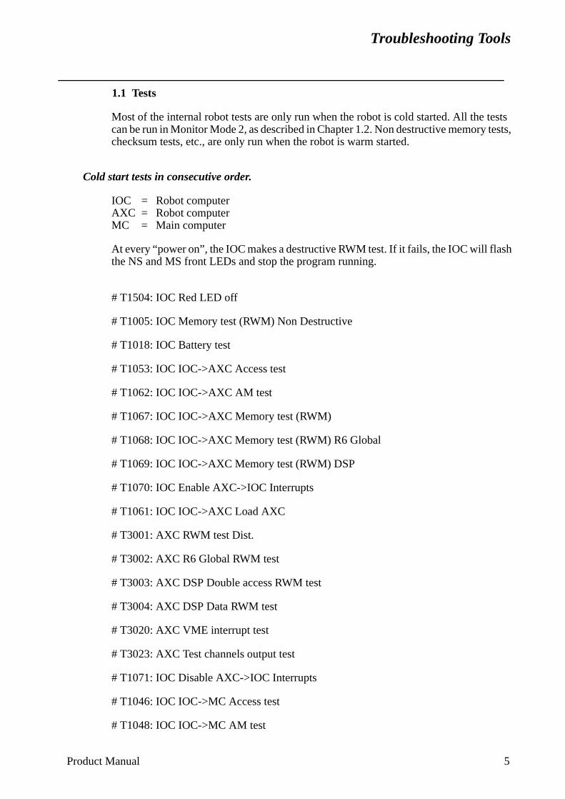
Troubleshooting Tools
sh
1.1 Tests
Most of the internal robot tests are only run when the robot is cold started. All the tests can be run in Monitor Mode 2, as described in Chapter 1.2. Non destructive memory tests, checksum tests, etc., are only run when the robot is warm started.
Cold start tests in consecutive order.
IOC = Robot computerAXC = Robot computerMC = Main computer
At every “power on”, the IOC makes a destructive RWM test. If it fails, the IOC will flathe NS and MS front LEDs and stop the program running.
# T1504: IOC Red LED off
# T1005: IOC Memory test (RWM) Non Destructive
# T1018: IOC Battery test
# T1053: IOC IOC->AXC Access test
# T1062: IOC IOC->AXC AM test
# T1067: IOC IOC->AXC Memory test (RWM)
# T1068: IOC IOC->AXC Memory test (RWM) R6 Global
# T1069: IOC IOC->AXC Memory test (RWM) DSP
# T1070: IOC Enable AXC->IOC Interrupts
# T1061: IOC IOC->AXC Load AXC
# T3001: AXC RWM test Dist.
# T3002: AXC R6 Global RWM test
# T3003: AXC DSP Double access RWM test
# T3004: AXC DSP Data RWM test
# T3020: AXC VME interrupt test
# T3023: AXC Test channels output test
# T1071: IOC Disable AXC->IOC Interrupts
# T1046: IOC IOC->MC Access test
# T1048: IOC IOC->MC AM test
Product Manual 5
Troubleshooting Tools
ill
ected
# T1050: IOC IOC->MC Memory test Destructive, Low win
# T1506: IOC IOC->MC LED off
# T1508: IOC IOC->ERWM LED off
# T1512: IOC IOC->MC Load MC
# T1509: IOC IOC->MC Release MC
# T2002: MC Memory test (RWM) Destructive
# T2010: MC Memory test (RWM) BM Destructive
# T1510: IOC IOC->MC Reset MC
Warm start tests in consecutive order.
IOC = Robot computer
At every “power on”, the IOC makes a destructive RWM test. If it fails, the IOC wflash the NS and MS front LEDs and stop the program running.
# T1504: IOC LED off
# T1005: IOC Memory test (RWM) Non Destructive
# T1018: IOC Battery test
1.2 Monitor Mode 2
When the system is in Monitor Mode 2, a large number of tests can be run.
These tests must be performed only by authorised service personnel. It should be noted that some of the tests will cause activity on customer connections and drive systems, which can result in damage, accidents etc. unless suitable precautionary measures are taken. It is advisable to disconnect all the connections involved dur-ing these tests.
To ensure that all memory addresses are resetted after testing shall the system be cold started.
The test mode Monitor mode 2 can be run from the teach pendant and/or a connPC/terminal.
6 Product Manual
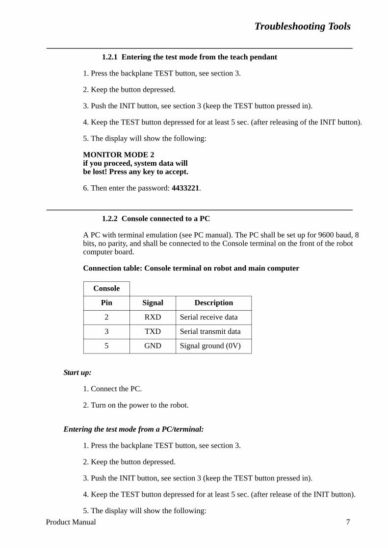
Troubleshooting Tools
1.2.1 Entering the test mode from the teach pendant
1. Press the backplane TEST button, see section 3.
2. Keep the button depressed.
3. Push the INIT button, see section 3 (keep the TEST button pressed in).
4. Keep the TEST button depressed for at least 5 sec. (after releasing of the INIT button).
5. The display will show the following:
MONITOR MODE 2if you proceed, system data willbe lost! Press any key to accept.
6. Then enter the password: 4433221.
1.2.2 Console connected to a PC
A PC with terminal emulation (see PC manual). The PC shall be set up for 9600 baud, 8 bits, no parity, and shall be connected to the Console terminal on the front of the robot computer board.
Connection table: Console terminal on robot and main computer
Start up:
1. Connect the PC.
2. Turn on the power to the robot.
Entering the test mode from a PC/terminal:
1. Press the backplane TEST button, see section 3.
2. Keep the button depressed.
3. Push the INIT button, see section 3 (keep the TEST button pressed in).
4. Keep the TEST button depressed for at least 5 sec. (after release of the INIT button).
5. The display will show the following:
Console
Pin Signal Description
2 RXD Serial receive data
3 TXD Serial transmit data
5 GND Signal ground (0V)
Product Manual 7
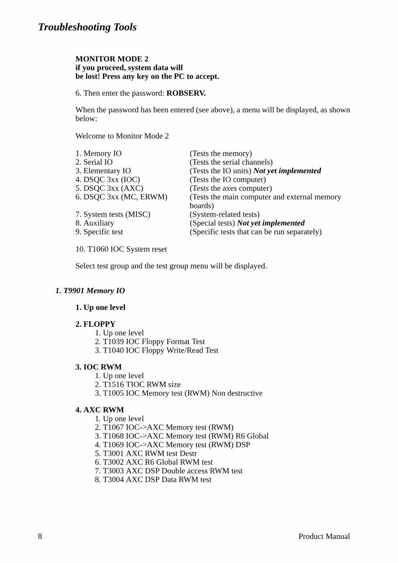
Troubleshooting Tools
MONITOR MODE 2if you proceed, system data willbe lost! Press any key on the PC to accept.
6. Then enter the password: ROBSERV.
When the password has been entered (see above), a menu will be displayed, as shown below:
Welcome to Monitor Mode 2
1. Memory IO (Tests the memory)2. Serial IO (Tests the serial channels)3. Elementary IO (Tests the IO units) Not yet implemented4. DSQC 3xx (IOC) (Tests the IO computer)5. DSQC 3xx (AXC) (Tests the axes computer)6. DSQC 3xx (MC, ERWM) (Tests the main computer and external memory
boards)7. System tests (MISC) (System-related tests)8. Auxiliary (Special tests) Not yet implemented9. Specific test (Specific tests that can be run separately)
10. T1060 IOC System reset
Select test group and the test group menu will be displayed.
1. T9901 Memory IO
1. Up one level
2. FLOPPY1. Up one level2. T1039 IOC Floppy Format Test3. T1040 IOC Floppy Write/Read Test
3. IOC RWM1. Up one level2. T1516 TIOC RWM size3. T1005 IOC Memory test (RWM) Non destructive
4. AXC RWM1. Up one level2. T1067 IOC->AXC Memory test (RWM)3. T1068 IOC->AXC Memory test (RWM) R6 Global4. T1069 IOC->AXC Memory test (RWM) DSP5. T3001 AXC RWM test Destr6. T3002 AXC R6 Global RWM test7. T3003 AXC DSP Double access RWM test8. T3004 AXC DSP Data RWM test
8 Product Manual
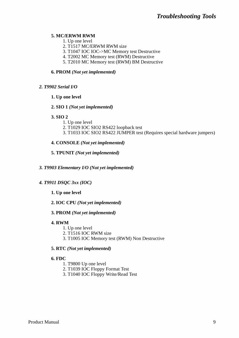
Troubleshooting Tools
5. MC/ERWM RWM1. Up one level2. T1517 MC/ERWM RWM size3. T1047 IOC IOC->MC Memory test Destructive4. T2002 MC Memory test (RWM) Destructive5. T2010 MC Memory test (RWM) BM Destructive
6. PROM (Not yet implemented)
2. T9902 Serial I/O
1. Up one level
2. SIO 1 (Not yet implemented)
3. SIO 2 1. Up one level2. T1029 IOC SIO2 RS422 loopback test3. T1033 IOC SIO2 RS422 JUMPER test (Requires special hardware jumpers)
4. CONSOLE (Not yet implemented)
5. TPUNIT (Not yet implemented)
3. T9903 Elementary I/O (Not yet implemented)
4. T9911 DSQC 3xx (IOC)
1. Up one level
2. IOC CPU (Not yet implemented)
3. PROM (Not yet implemented)
4. RWM 1. Up one level2. T1516 IOC RWM size3. T1005 IOC Memory test (RWM) Non Destructive
5. RTC (Not yet implemented)
6. FDC 1. T9800 Up one level2. T1039 IOC Floppy Format Test3. T1040 IOC Floppy Write/Read Test
Product Manual 9
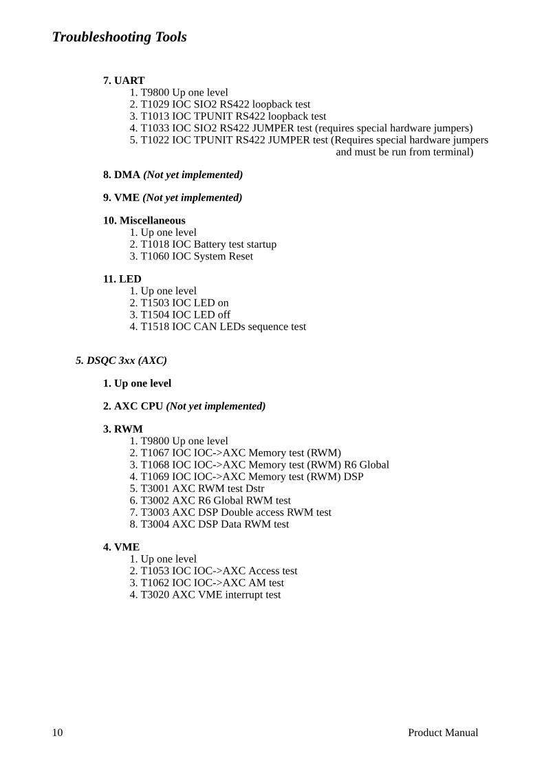
Troubleshooting Tools
7. UART 1. T9800 Up one level2. T1029 IOC SIO2 RS422 loopback test3. T1013 IOC TPUNIT RS422 loopback test4. T1033 IOC SIO2 RS422 JUMPER test (requires special hardware jumpers)5. T1022 IOC TPUNIT RS422 JUMPER test (Requires special hardware jumpers
and must be run from terminal)
8. DMA (Not yet implemented)
9. VME (Not yet implemented)
10. Miscellaneous 1. Up one level2. T1018 IOC Battery test startup3. T1060 IOC System Reset
11. LED 1. Up one level2. T1503 IOC LED on3. T1504 IOC LED off4. T1518 IOC CAN LEDs sequence test
5. DSQC 3xx (AXC)
1. Up one level
2. AXC CPU (Not yet implemented)
3. RWM 1. T9800 Up one level2. T1067 IOC IOC->AXC Memory test (RWM)3. T1068 IOC IOC->AXC Memory test (RWM) R6 Global4. T1069 IOC IOC->AXC Memory test (RWM) DSP5. T3001 AXC RWM test Dstr6. T3002 AXC R6 Global RWM test7. T3003 AXC DSP Double access RWM test8. T3004 AXC DSP Data RWM test
4. VME 1. Up one level2. T1053 IOC IOC->AXC Access test3. T1062 IOC IOC->AXC AM test4. T3020 AXC VME interrupt test
10 Product Manual
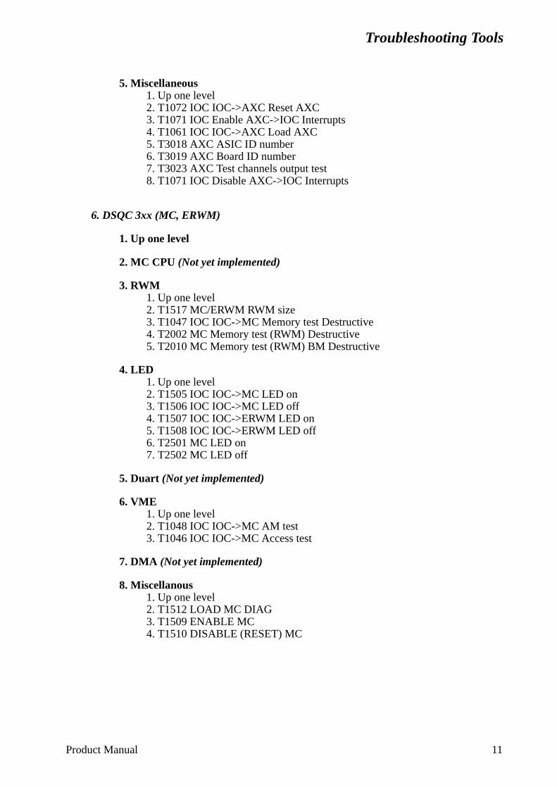
Troubleshooting Tools
5. Miscellaneous 1. Up one level2. T1072 IOC IOC->AXC Reset AXC3. T1071 IOC Enable AXC->IOC Interrupts4. T1061 IOC IOC->AXC Load AXC5. T3018 AXC ASIC ID number6. T3019 AXC Board ID number7. T3023 AXC Test channels output test8. T1071 IOC Disable AXC->IOC Interrupts
6. DSQC 3xx (MC, ERWM)
1. Up one level
2. MC CPU (Not yet implemented)
3. RWM 1. Up one level2. T1517 MC/ERWM RWM size3. T1047 IOC IOC->MC Memory test Destructive4. T2002 MC Memory test (RWM) Destructive5. T2010 MC Memory test (RWM) BM Destructive
4. LED 1. Up one level2. T1505 IOC IOC->MC LED on3. T1506 IOC IOC->MC LED off4. T1507 IOC IOC->ERWM LED on5. T1508 IOC IOC->ERWM LED off6. T2501 MC LED on7. T2502 MC LED off
5. Duart (Not yet implemented)
6. VME 1. Up one level2. T1048 IOC IOC->MC AM test3. T1046 IOC IOC->MC Access test
7. DMA (Not yet implemented)
8. Miscellanous 1. Up one level2. T1512 LOAD MC DIAG3. T1509 ENABLE MC4. T1510 DISABLE (RESET) MC
Product Manual 11
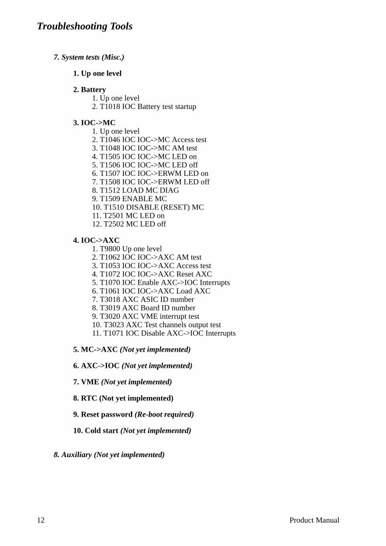
Troubleshooting Tools
7. System tests (Misc.)
1. Up one level
2. Battery 1. Up one level2. T1018 IOC Battery test startup
3. IOC->MC 1. Up one level2. T1046 IOC IOC->MC Access test3. T1048 IOC IOC->MC AM test4. T1505 IOC IOC->MC LED on5. T1506 IOC IOC->MC LED off6. T1507 IOC IOC->ERWM LED on7. T1508 IOC IOC->ERWM LED off8. T1512 LOAD MC DIAG9. T1509 ENABLE MC10. T1510 DISABLE (RESET) MC11. T2501 MC LED on12. T2502 MC LED off
4. IOC->AXC 1. T9800 Up one level2. T1062 IOC IOC->AXC AM test3. T1053 IOC IOC->AXC Access test4. T1072 IOC IOC->AXC Reset AXC5. T1070 IOC Enable AXC->IOC Interrupts6. T1061 IOC IOC->AXC Load AXC7. T3018 AXC ASIC ID number8. T3019 AXC Board ID number9. T3020 AXC VME interrupt test10. T3023 AXC Test channels output test11. T1071 IOC Disable AXC->IOC Interrupts
5. MC->AXC (Not yet implemented)
6. AXC->IOC (Not yet implemented)
7. VME (Not yet implemented)
8. RTC (Not yet implemented)
9. Reset password (Re-boot required)
10. Cold start (Not yet implemented)
8. Auxiliary (Not yet implemented)
12 Product Manual
Troubleshooting Tools
9. Specific test
Specific test Txxxx<Q> <q> or < > to quitEnter test number Txxxx: T
10. IOC System reset (Not yet implemented)
All available tests have been defined in Chapter 1.1.
Product Manual 13
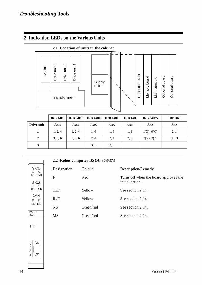
Troubleshooting Tools
1
4 Product Manual2 Indication LEDs on the Various Units
2.1 Location of units in the cabinet
2.2 Robot computer DSQC 363/373
Designation Colour Description/Remedy
F Red Turns off when the board approves the initialisation.
TxD Yellow See section 2.14.
RxD Yellow See section 2.14.
NS Green/red See section 2.14.
MS Green/red See section 2.14.
Transformer
DC
link
Driv
e un
it 3
Driv
e un
it 2
Driv
e un
it 1
Supply unit
Rob
ot c
ompu
ter
Mai
n co
mpu
ter
Opt
iona
l boa
rd
Opt
iona
l boa
rd
Mem
ory
boar
d
IRB 1400 IRB 2400 IRB 4400 IRB 6400 IRB 640 IRB 840/A IRB 340
Drive unit Axes Axes Axes Axes Axes Axes Axes
1 1, 2, 4 1, 2, 4 1, 6 1, 6 1, 6 1(X), 6(C) 2, 1
2 3, 5, 6 3, 5, 6 2, 4 2, 4 2, 3 2(Y), 3(Z) (4), 3
3 3, 5 3, 5
F
DSQC322
SIO1
SIO2
CAN
NS MS
TxD
TxD RxD
RxD
CONSOLE

Troubleshooting Tools
2.3 Main computer DSQC 361
Designation Colour Description/Remedy
F Red Turns off when the board approves the initialisation.
2.4 Memory board DSQC 324/16Mb, 323/8Mb
Designation Colour Description/Remedy
F Red Turns off when the board approves the initialisation.
DSQC361
F
DSQC3xx
F
Product Manual 15
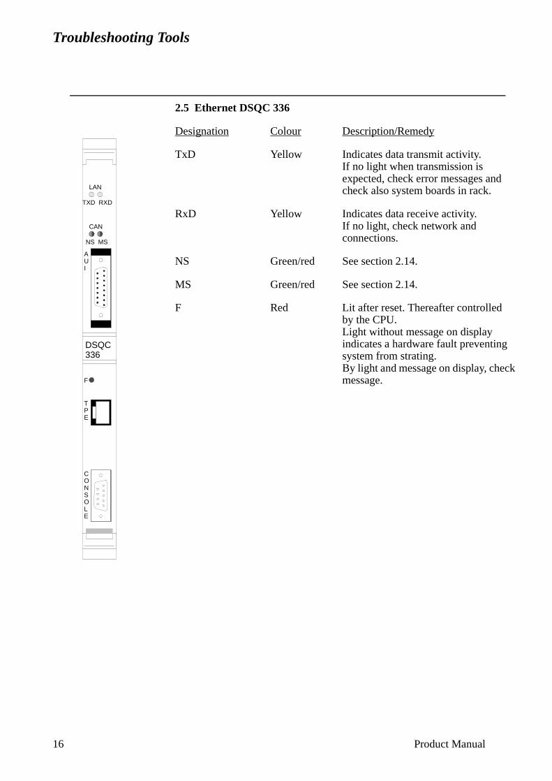
Troubleshooting Tools
16
2.5 Ethernet DSQC 336
Designation Colour Description/Remedy
TxD Yellow Indicates data transmit activity.If no light when transmission is expected, check error messages andcheck also system boards in rack.
RxD Yellow Indicates data receive activity.If no light, check network and connections.
NS Green/red See section 2.14.
MS Green/red See section 2.14.
F Red Lit after reset. Thereafter controlledby the CPU.Light without message on display indicates a hardware fault preventingsystem from strating.By light and message on display, check message.
DSQC336
LAN
TXD RXD
CAN
NS MS
AUI
F
TPE
CONSOLE
Product Manual
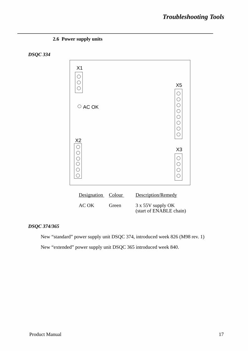
Troubleshooting Tools
2.6 Power supply units
DSQC 334
Designation Colour Description/Remedy
AC OK Green 3 x 55V supply OK(start of ENABLE chain)
DSQC 374/365
New “standard” power supply unit DSQC 374, introduced week 826 (M98 rev. 1)
New “extended” power supply unit DSQC 365 introduced week 840.
AC OK
X1
X5
X2
X3
Product Manual 17
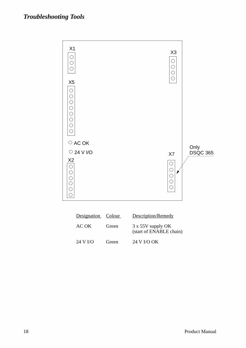
Troubleshooting Tools
Designation Colour Description/Remedy
AC OK Green 3 x 55V supply OK(start of ENABLE chain)
24 V I/O Green 24 V I/O OK
AC OK
X1
X5
X2
X3
24 V I/O X7OnlyDSQC 365
18 Product Manual
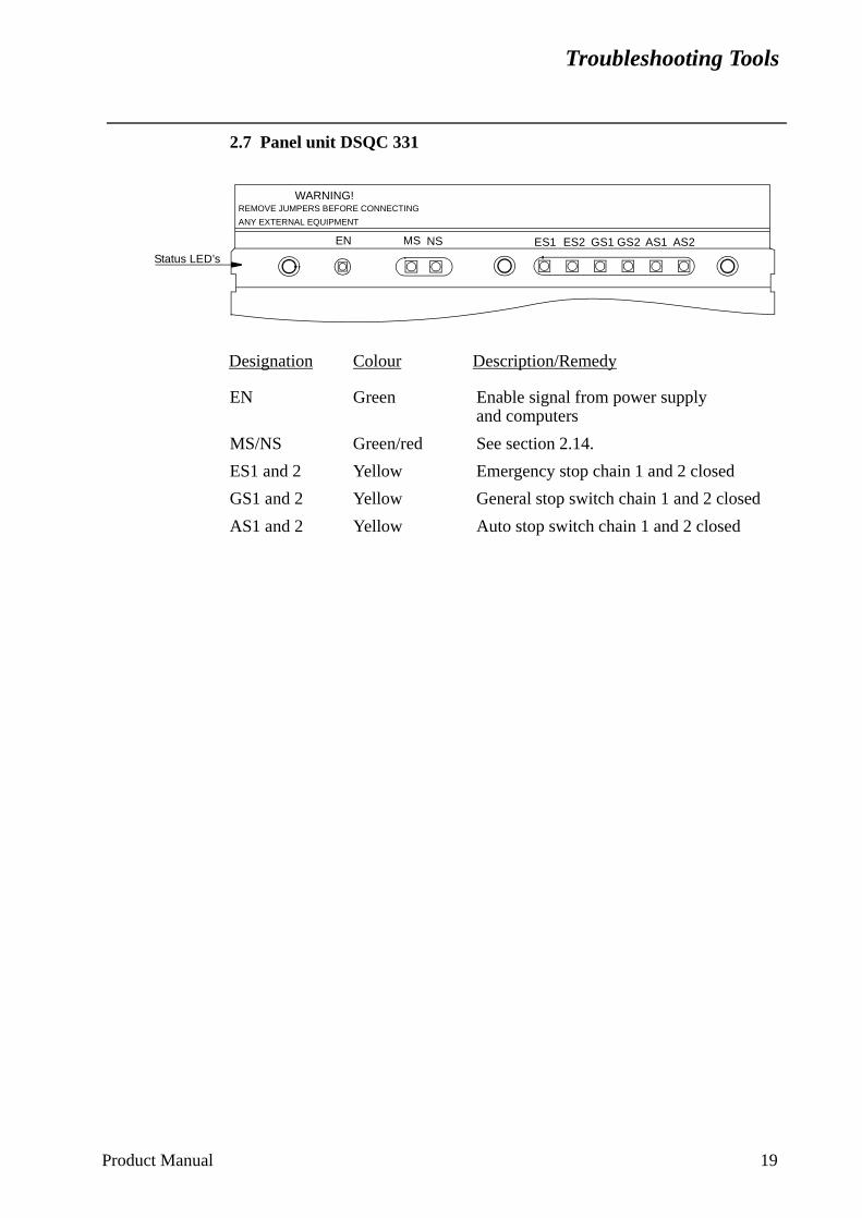
Troubleshooting Tools
2.7 Panel unit DSQC 331
Designation Colour Description/Remedy
EN Green Enable signal from power supplyand computers
MS/NS Green/red See section 2.14.
ES1 and 2 Yellow Emergency stop chain 1 and 2 closed
GS1 and 2 Yellow General stop switch chain 1 and 2 closed
AS1 and 2 Yellow Auto stop switch chain 1 and 2 closed
AS2AS1GS1ES2ES1 GS2NSMSEN
WARNING!REMOVE JUMPERS BEFORE CONNECTING
ANY EXTERNAL EQUIPMENT
Status LED’s
Product Manual 19
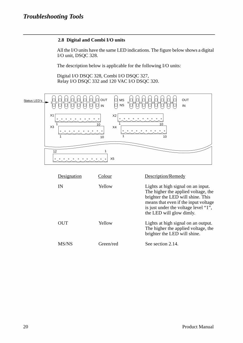
Troubleshooting Tools
2.8 Digital and Combi I/O units
All the I/O units have the same LED indications. The figure below shows a digital I/O unit, DSQC 328.
The description below is applicable for the following I/O units:
Digital I/O DSQC 328, Combi I/O DSQC 327, Relay I/O DSQC 332 and 120 VAC I/O DSQC 320.
Designation Colour Description/Remedy
IN Yellow Lights at high signal on an input. The higher the applied voltage, the brighter the LED will shine. This means that even if the input voltage is just under the voltage level “1”, the LED will glow dimly.
OUT Yellow Lights at high signal on an output.The higher the applied voltage, thebrighter the LED will shine.
MS/NS Green/red See section 2.14.
OUT
INNS
MS16151413121110987654321
OUT
IN
X1
X3
X2
X4
101101
101 101
Status LED’s
X5
112
20 Product Manual
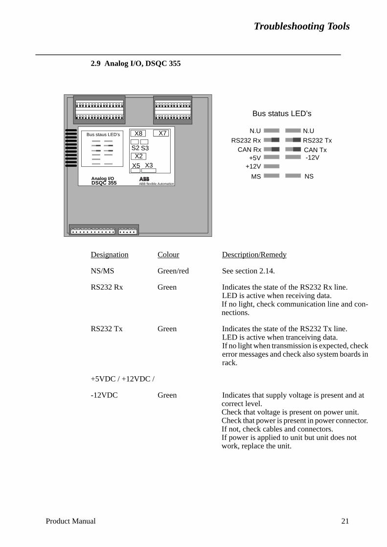
Troubleshooting Tools
2.9 Analog I/O, DSQC 355
Designation Colour Description/Remedy
NS/MS Green/red See section 2.14.
RS232 Rx Green Indicates the state of the RS232 Rx line.LED is active when receiving data.If no light, check communication line and con-nections.
RS232 Tx Green Indicates the state of the RS232 Tx line. LED is active when tranceiving data.If no light when transmission is expected, check error messages and check also system boards in rack.
+5VDC / +12VDC /
-12VDC Green Indicates that supply voltage is present and at correct level.Check that voltage is present on power unit.Check that power is present in power connector. If not, check cables and connectors.If power is applied to unit but unit does not work, replace the unit.
DSQC 355 ABB flexible Automation
N.U
MS
RS232 Rx
+5V
Bus status LED’s
CAN Rx
+12V
RS232 Tx
N.U
CAN Tx-12V
NS
Bus staus LED’s
Analog I/O
X8
S3S2
X3X5
X2
X7
Product Manual 21
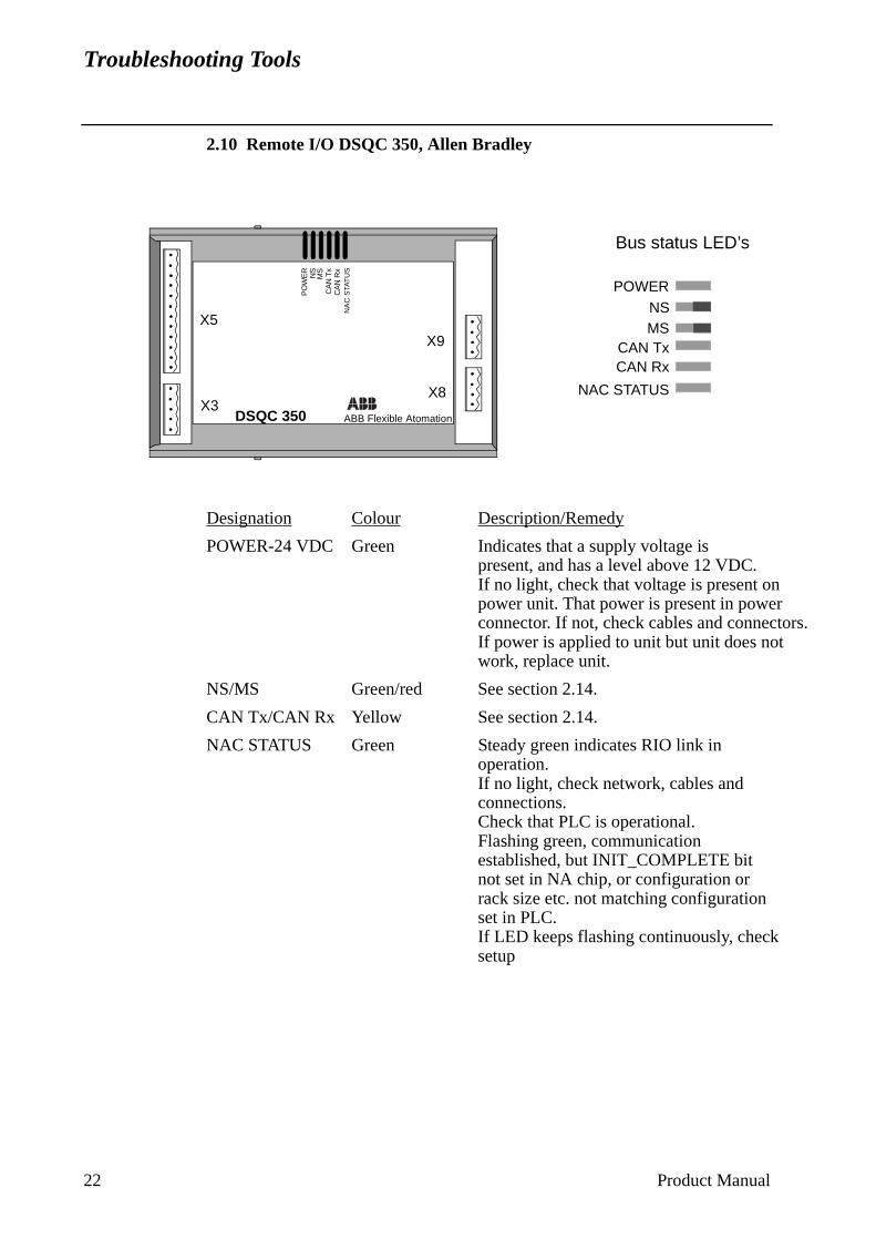
Troubleshooting Tools
2.10 Remote I/O DSQC 350, Allen Bradley
Designation Colour Description/Remedy
POWER-24 VDC Green Indicates that a supply voltage is present, and has a level above 12 VDC.If no light, check that voltage is present on power unit. That power is present in powerconnector. If not, check cables and connectors.If power is applied to unit but unit does not work, replace unit.
NS/MS Green/red See section 2.14.
CAN Tx/CAN Rx Yellow See section 2.14.
NAC STATUS Green Steady green indicates RIO link inoperation.If no light, check network, cables and connections.Check that PLC is operational.Flashing green, communication established, but INIT_COMPLETE bit not set in NA chip, or configuration or rack size etc. not matching configuration set in PLC.If LED keeps flashing continuously, check setup
Bus status LED’s
DSQC 350 ABB Flexible Atomation
POWER
NAC STATUS
CAN TxCAN Rx
NSMS
X8
X9
X5
X3
CA
N R
xN
AC
STA
TU
S
CA
N T
xM
SN
SP
OW
ER
22 Product Manual
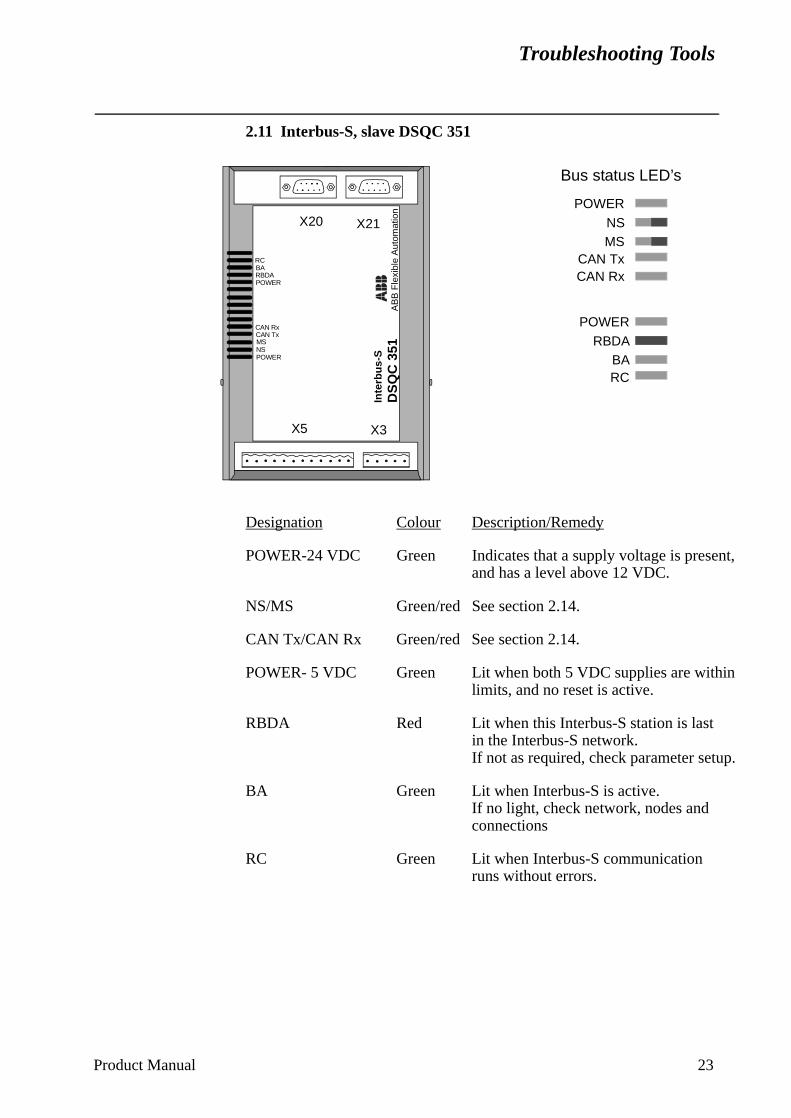
Troubleshooting Tools
2.11 Interbus-S, slave DSQC 351
Designation Colour Description/Remedy
POWER-24 VDC Green Indicates that a supply voltage is present,and has a level above 12 VDC.
NS/MS Green/red See section 2.14.
CAN Tx/CAN Rx Green/red See section 2.14.
POWER- 5 VDC Green Lit when both 5 VDC supplies are within limits, and no reset is active.
RBDA Red Lit when this Interbus-S station is last in the Interbus-S network.If not as required, check parameter setup.
BA Green Lit when Interbus-S is active.If no light, check network, nodes and connections
RC Green Lit when Interbus-S communicationruns without errors.
Bus status LED’s
DS
QC
351
AB
B F
lexi
ble
Aut
omat
ion
POWER
CAN TxCAN Rx
NSMS
POWER
RC
RBDABA
Inte
rbu
s-S
X3X5
X21X20
POWER
CAN TxMSNS
RC
POWER
RBDABA
CAN Rx
Product Manual 23
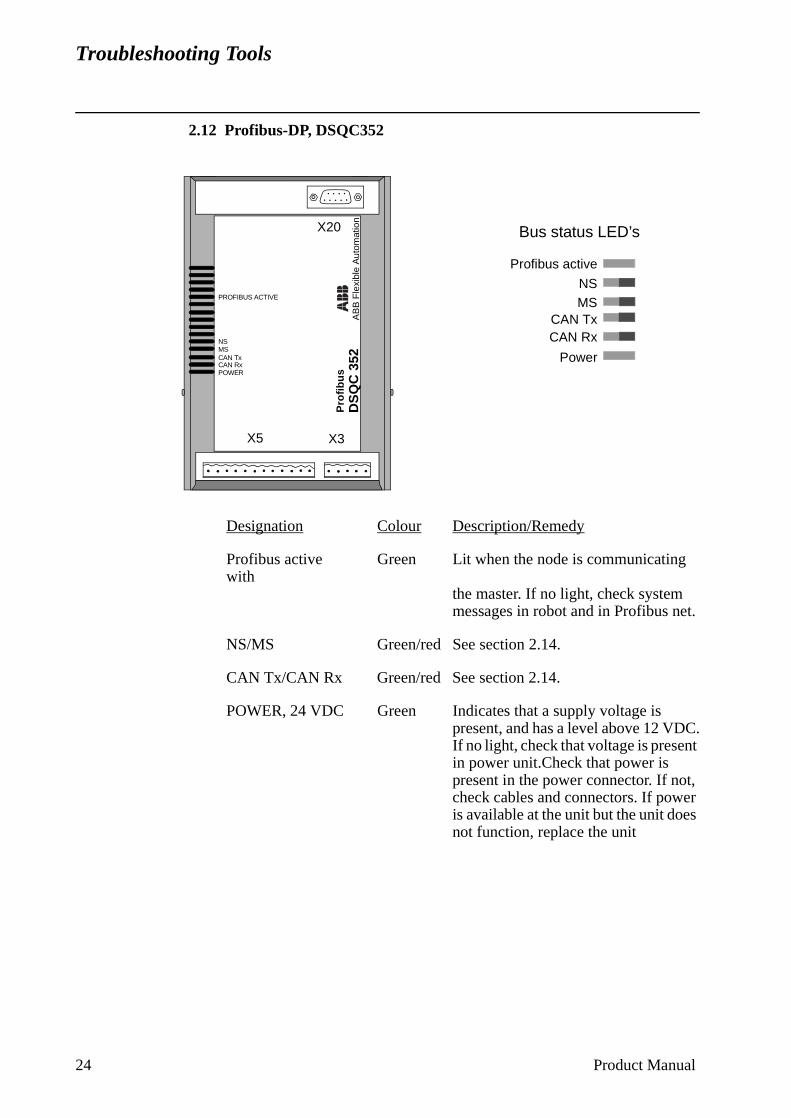
Troubleshooting Tools
2.12 Profibus-DP, DSQC352
Designation Colour Description/Remedy
Profibus active Green Lit when the node is communicating with
the master. If no light, check system messages in robot and in Profibus net.
NS/MS Green/red See section 2.14.
CAN Tx/CAN Rx Green/red See section 2.14.
POWER, 24 VDC Green Indicates that a supply voltage is present, and has a level above 12 VDC.If no light, check that voltage is present in power unit.Check that power is present in the power connector. If not, check cables and connectors. If power is available at the unit but the unit does not function, replace the unit
Profibus active
Power
NSMS
CAN RxCAN Tx
Bus status LED’s
DS
QC
352
AB
B F
lexi
ble
Aut
omat
ion
CAN TxMS
POWERCAN Rx
PROFIBUS ACTIVE
X20
X5 X3
Pro
fib
us
NS
24 Product Manual
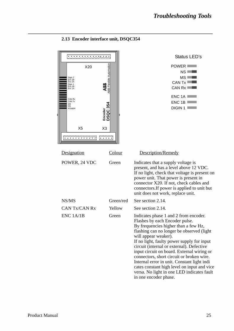
Troubleshooting Tools
2.13 Encoder interface unit, DSQC354
Designation Colour Description/Remedy
POWER, 24 VDC Green Indicates that a supply voltage is present, and has a level above 12 VDC.If no light, check that voltage is present on power unit. That power is present in connector X20. If not, check cables and connectors.If power is applied to unit but unit does not work, replace unit.
NS/MS Green/red See section 2.14.
CAN Tx/CAN Rx Yellow See section 2.14.
ENC 1A/1B Green Indicates phase 1 and 2 from encoder.Flashes by each Encoder pulse.By frequencies higher than a few Hz, flashing can no longer be observed (light will appear weaker).If no light, faulty power supply for input circuit (internal or external). Defective input circuit on board. External wiring or connectors, short circuit or broken wire.Internal error in unit. Constant light indicates constant high level on input and vice versa. No light in one LED indicates fault in one encoder phase.
POWER
NSMS
CAN RxCAN Tx
Status LED’s
DS
QC
354
AB
B F
lexi
ble
Aut
omat
ion
ENC 1A
ENC 1BDIGIN 1
X20
X5 X3
En
cod
er
Digin 1
CAN TxMSNSPOWER
CAN Rx
Enc 2AEnc 2BDigin 2
Enc 1AEnc 1B
Product Manual 25

Troubleshooting Tools
DIGIN1 Green Digital input. Lit when digital input is active. The input is used for external start signal/conveyor synchronization point.If no light, faulty limit switch, photocell etc. External wiring or connectors, short circuit or broken wire. Faulty power supplyfor input circuit (internal or external). Defective input circuit on board.
26 Product Manual
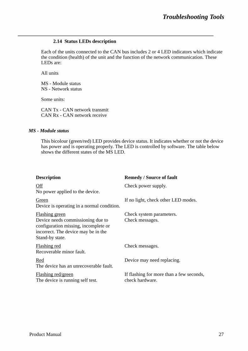
Troubleshooting Tools
2.14 Status LEDs description
Each of the units connected to the CAN bus includes 2 or 4 LED indicators which indicate the condition (health) of the unit and the function of the network communication. These LEDs are:
All units
MS - Module status NS - Network status
Some units:
CAN Tx - CAN network transmit CAN Rx - CAN network receive
MS - Module status
This bicolour (green/red) LED provides device status. It indicates whether or not the device has power and is operating properly. The LED is controlled by software. The table below shows the different states of the MS LED.
Description Remedy / Source of fault
OffNo power applied to the device.
Check power supply.
GreenDevice is operating in a normal condition.
If no light, check other LED modes.
Flashing greenDevice needs commissioning due to configuration missing, incomplete or incorrect. The device may be in the Stand-by state.
Check system parameters.Check messages.
Flashing redRecoverable minor fault.
Check messages.
RedThe device has an unrecoverable fault.
Device may need replacing.
Flashing red/greenThe device is running self test.
If flashing for more than a few seconds, check hardware.
Product Manual 27
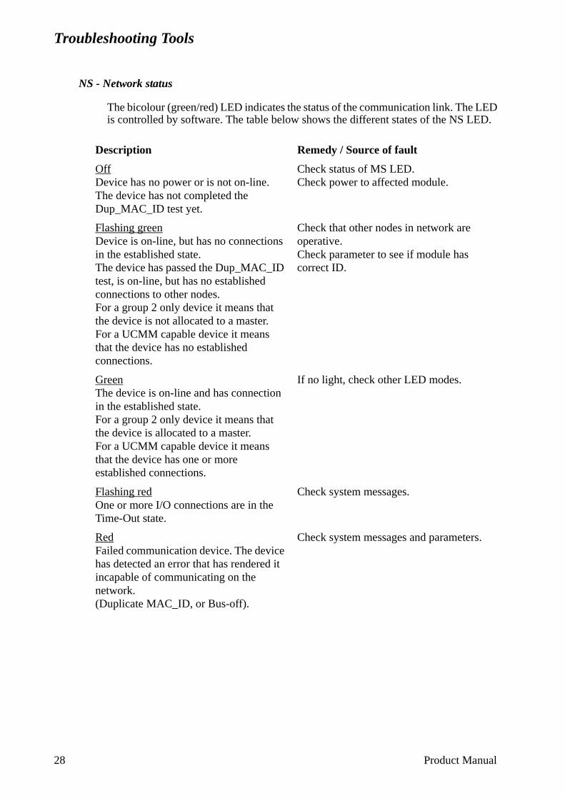
Troubleshooting Tools
NS - Network status
The bicolour (green/red) LED indicates the status of the communication link. The LED is controlled by software. The table below shows the different states of the NS LED.
Description Remedy / Source of fault
OffDevice has no power or is not on-line.The device has not completed the Dup_MAC_ID test yet.
Check status of MS LED.Check power to affected module.
Flashing greenDevice is on-line, but has no connections in the established state.The device has passed the Dup_MAC_ID test, is on-line, but has no established connections to other nodes.For a group 2 only device it means that the device is not allocated to a master.For a UCMM capable device it means that the device has no established connections.
Check that other nodes in network are operative.Check parameter to see if module has correct ID.
GreenThe device is on-line and has connection in the established state.For a group 2 only device it means that the device is allocated to a master.For a UCMM capable device it means that the device has one or more established connections.
If no light, check other LED modes.
Flashing redOne or more I/O connections are in the Time-Out state.
Check system messages.
RedFailed communication device. The device has detected an error that has rendered it incapable of communicating on the network.(Duplicate MAC_ID, or Bus-off).
Check system messages and parameters.
28 Product Manual
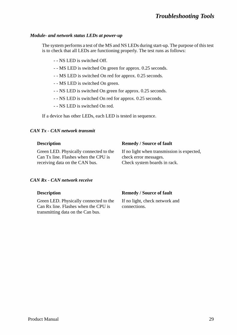
Troubleshooting Tools
Module- and network status LEDs at power-up
The system performs a test of the MS and NS LEDs during start-up. The purpose of this test is to check that all LEDs are functioning properly. The test runs as follows:
- - NS LED is switched Off.
- - MS LED is switched On green for approx. 0.25 seconds.
- - MS LED is switched On red for approx. 0.25 seconds.
- - MS LED is switched On green.
- - NS LED is switched On green for approx. 0.25 seconds.
- - NS LED is switched On red for approx. 0.25 seconds.
- - NS LED is switched On red.
If a device has other LEDs, each LED is tested in sequence.
CAN Tx - CAN network transmit
CAN Rx - CAN network receive
Description Remedy / Source of fault
Green LED. Physically connected to the Can Tx line. Flashes when the CPU is receiving data on the CAN bus.
If no light when transmission is expected, check error messages.Check system boards in rack.
Description Remedy / Source of fault
Green LED. Physically connected to the Can Rx line. Flashes when the CPU is transmitting data on the Can bus.
If no light, check network and connections.
Product Manual 29
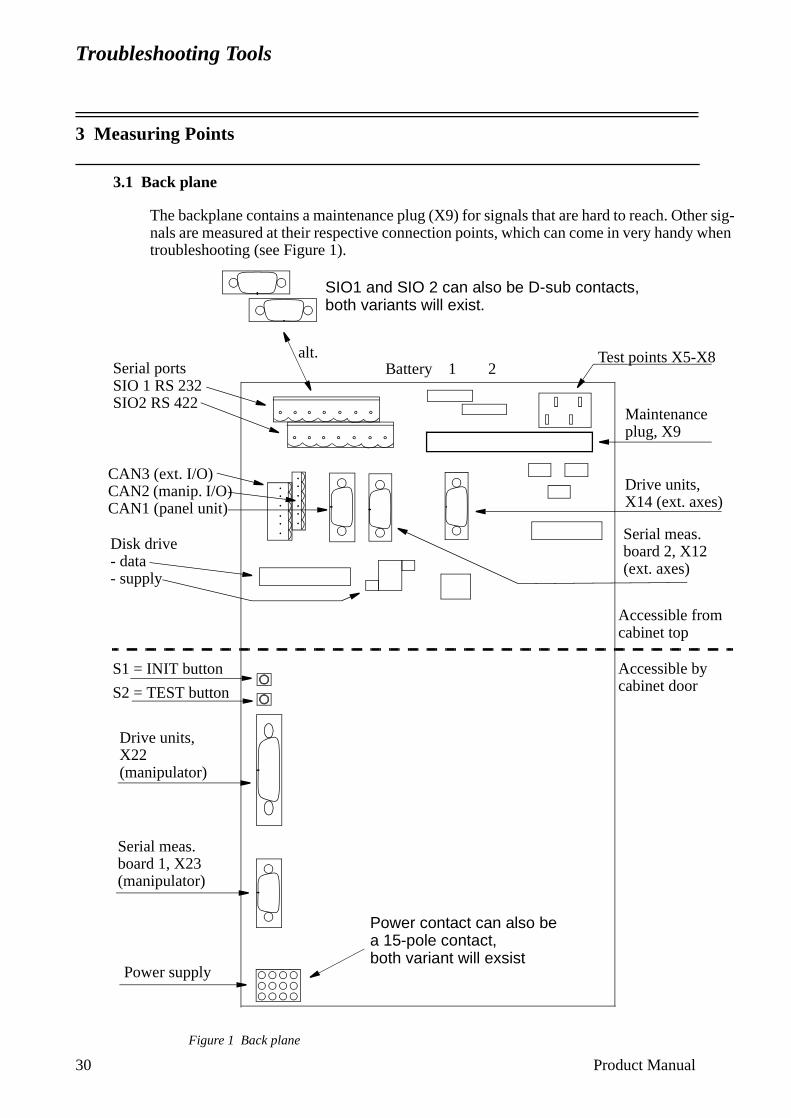
Troubleshooting Tools
3 Measuring Points
3.1 Back plane
The backplane contains a maintenance plug (X9) for signals that are hard to reach. Other sig-nals are measured at their respective connection points, which can come in very handy when troubleshooting (see Figure 1).
Figure 1 Back plane
S1 = INIT button
S2 = TEST button
Accessible from cabinet top
Maintenance plug, X9
Battery 1 2Serial portsSIO 1 RS 232SIO2 RS 422
CAN3 (ext. I/O)CAN2 (manip. I/O)CAN1 (panel unit)
Disk drive- data- supply
Drive units, X14 (ext. axes)
Serial meas.board 2, X12(ext. axes)
Serial meas. board 1, X23(manipulator)
Power supply
Drive units, X22(manipulator)
Test points X5-X8
Accessible by cabinet door
alt.
SIO1 and SIO 2 can also be D-sub contacts, both variants will exist.
Power contact can also be a 15-pole contact,both variant will exsist
30 Product Manual
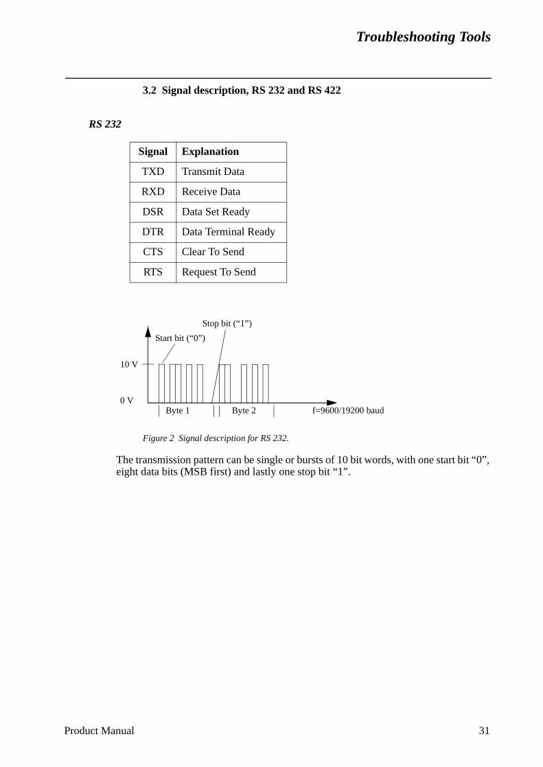
Troubleshooting Tools
t “0”,
3.2 Signal description, RS 232 and RS 422
RS 232
Figure 2 Signal description for RS 232.
The transmission pattern can be single or bursts of 10 bit words, with one start bieight data bits (MSB first) and lastly one stop bit “1”.
Signal Explanation
TXD Transmit Data
RXD Receive Data
DSR Data Set Ready
DTR Data Terminal Ready
CTS Clear To Send
RTS Request To Send
Start bit (“0”)
Stop bit (“1”)
f=9600/19200 baudByte 1 Byte 2
10 V
0 V
Product Manual 31
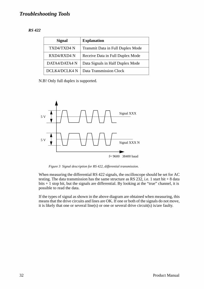
Troubleshooting Tools
it is
g, this ove,
RS 422
N.B! Only full duplex is supported.
Figure 3 Signal description for RS 422, differential transmission.
When measuring the differential RS 422 signals, the oscilloscope should be set for AC testing. The data transmission has the same structure as RS 232, i.e. 1 start bit + 8 data bits + 1 stop bit, but the signals are differential. By looking at the “true” channel, possible to read the data.
If the types of signal as shown in the above diagram are obtained when measurinmeans that the drive circuits and lines are OK. If one or both of the signals do not mit is likely that one or several line(s) or one or several drive circuit(s) is/are faulty.
Signal Explanation
TXD4/TXD4 N Transmit Data in Full Duplex Mode
RXD4/RXD4 N Receive Data in Full Duplex Mode
DATA4/DATA4 N Data Signals in Half Duplex Mode
DCLK4/DCLK4 N Data Transmission Clock
f= 9600 38400 baud
Signal XXX N
Signal XXX5 V
5 V
32 Product Manual
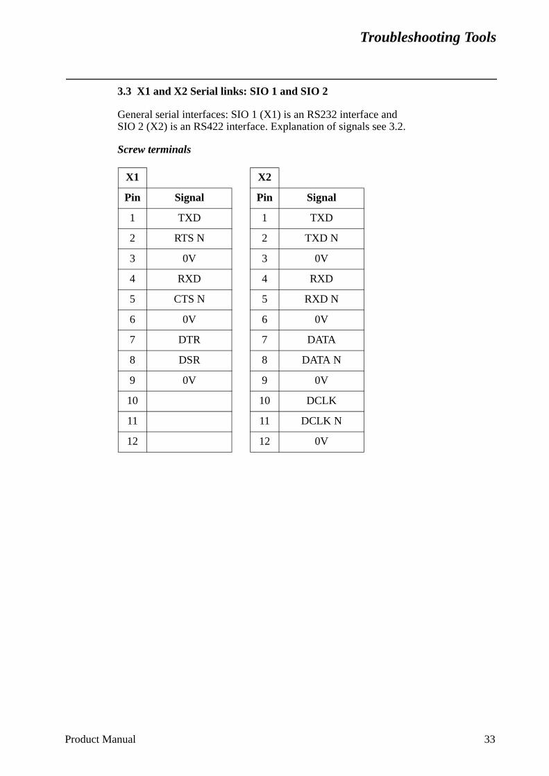
Troubleshooting Tools
3.3 X1 and X2 Serial links: SIO 1 and SIO 2
General serial interfaces: SIO 1 (X1) is an RS232 interface and SIO 2 (X2) is an RS422 interface. Explanation of signals see 3.2.
Screw terminals
X1 X2
Pin Signal Pin Signal
1 TXD 1 TXD
2 RTS N 2 TXD N
3 0V 3 0V
4 RXD 4 RXD
5 CTS N 5 RXD N
6 0V 6 0V
7 DTR 7 DATA
8 DSR 8 DATA N
9 0V 9 0V
10 10 DCLK
11 11 DCLK N
12 12 0V
Product Manual 33
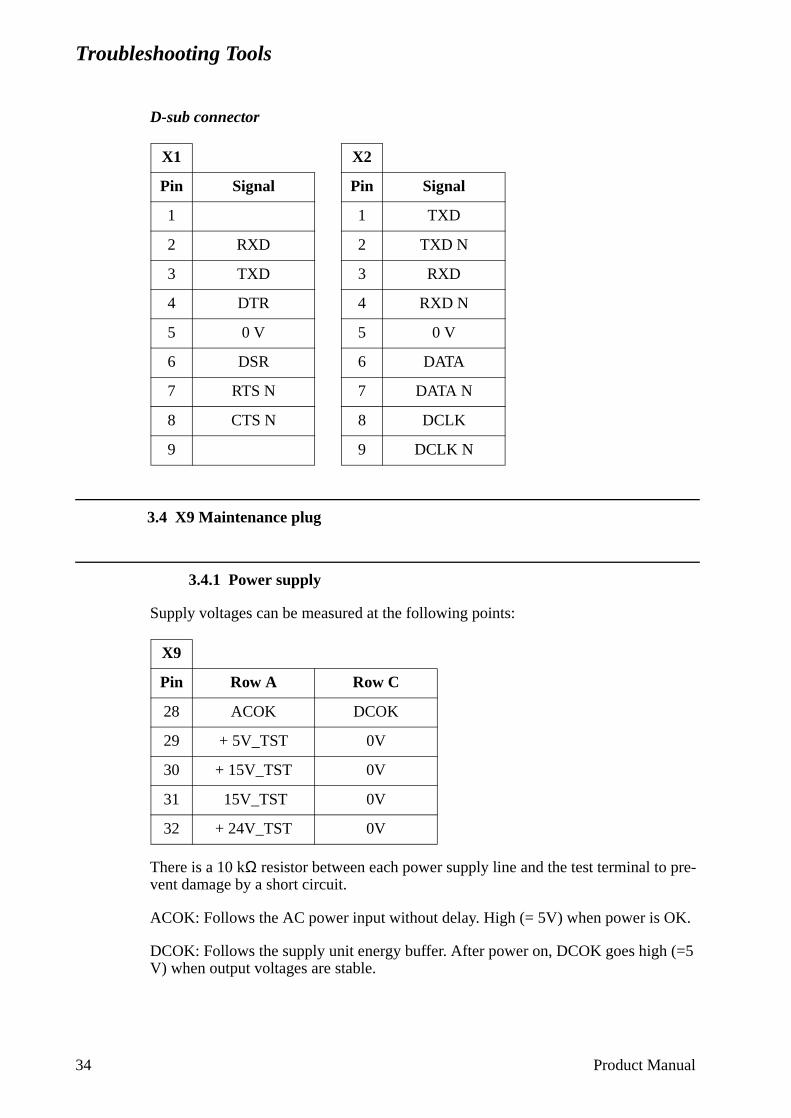
Troubleshooting Tools
D-sub connector
3.4 X9 Maintenance plug
3.4.1 Power supply
Supply voltages can be measured at the following points:
There is a 10 kΩ resistor between each power supply line and the test terminal to pre-vent damage by a short circuit.
ACOK: Follows the AC power input without delay. High (= 5V) when power is OK.
DCOK: Follows the supply unit energy buffer. After power on, DCOK goes high (=5 V) when output voltages are stable.
X1 X2
Pin Signal Pin Signal
1 1 TXD
2 RXD 2 TXD N
3 TXD 3 RXD
4 DTR 4 RXD N
5 0 V 5 0 V
6 DSR 6 DATA
7 RTS N 7 DATA N
8 CTS N 8 DCLK
9 9 DCLK N
X9
Pin Row A Row C
28 ACOK DCOK
29 + 5V_TST 0V
30 + 15V_TST 0V
31 15V_TST 0V
32 + 24V_TST 0V
34 Product Manual
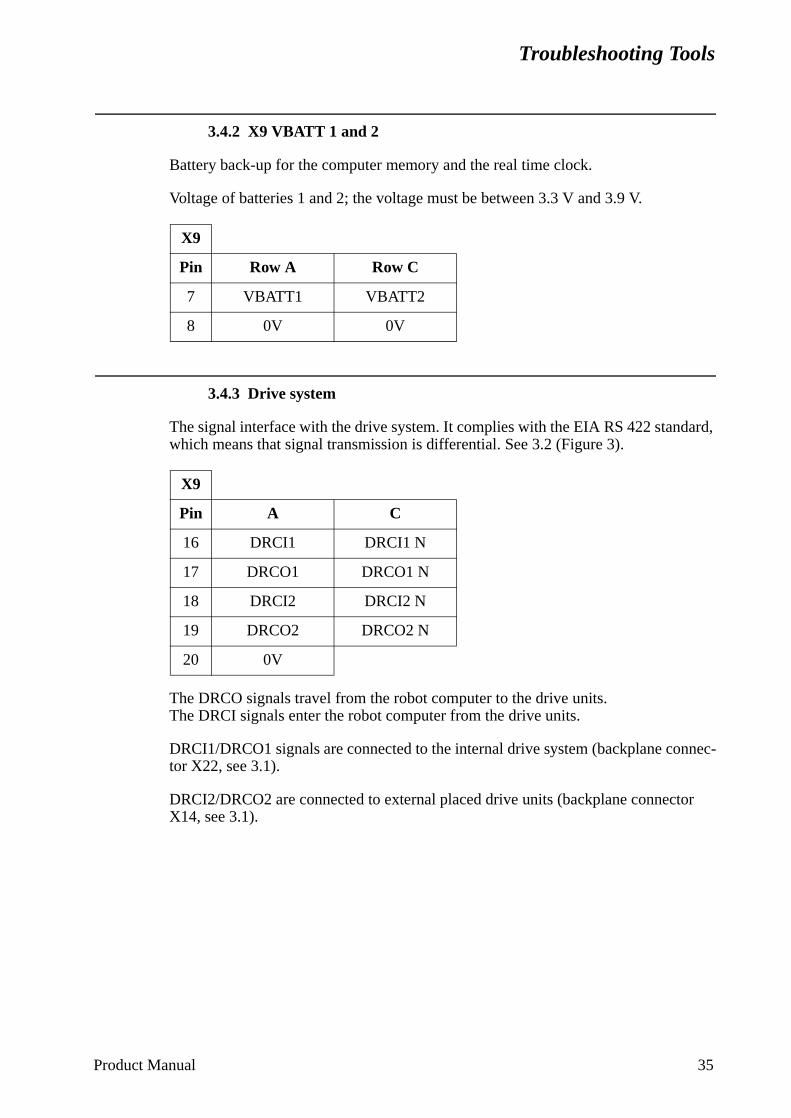
Troubleshooting Tools
3.4.2 X9 VBATT 1 and 2
Battery back-up for the computer memory and the real time clock.
Voltage of batteries 1 and 2; the voltage must be between 3.3 V and 3.9 V.
3.4.3 Drive system
The signal interface with the drive system. It complies with the EIA RS 422 standard, which means that signal transmission is differential. See 3.2 (Figure 3).
The DRCO signals travel from the robot computer to the drive units.The DRCI signals enter the robot computer from the drive units.
DRCI1/DRCO1 signals are connected to the internal drive system (backplane connec-tor X22, see 3.1).
DRCI2/DRCO2 are connected to external placed drive units (backplane connector X14, see 3.1).
X9
Pin Row A Row C
7 VBATT1 VBATT2
8 0V 0V
X9
Pin A C
16 DRCI1 DRCI1 N
17 DRCO1 DRCO1 N
18 DRCI2 DRCI2 N
19 DRCO2 DRCO2 N
20 0V
Product Manual 35
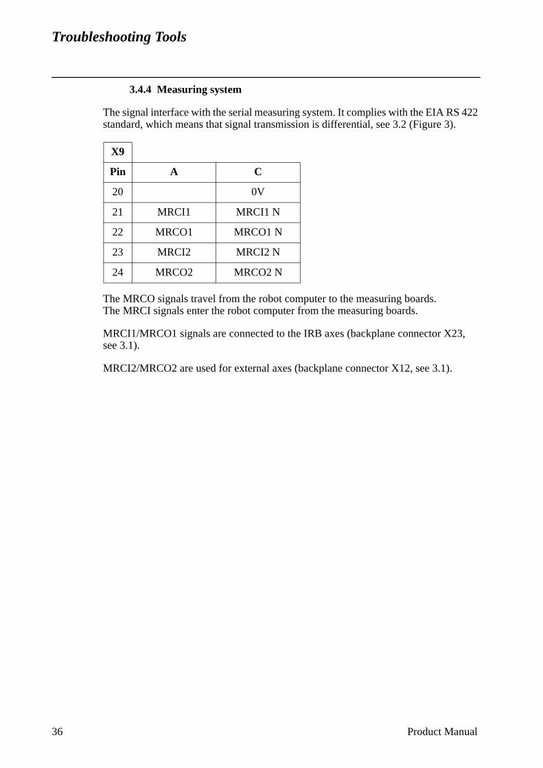
Troubleshooting Tools
3.4.4 Measuring system
The signal interface with the serial measuring system. It complies with the EIA RS 422 standard, which means that signal transmission is differential, see 3.2 (Figure 3).
The MRCO signals travel from the robot computer to the measuring boards.The MRCI signals enter the robot computer from the measuring boards.
MRCI1/MRCO1 signals are connected to the IRB axes (backplane connector X23, see 3.1).
MRCI2/MRCO2 are used for external axes (backplane connector X12, see 3.1).
X9
Pin A C
20 0V
21 MRCI1 MRCI1 N
22 MRCO1 MRCO1 N
23 MRCI2 MRCI2 N
24 MRCO2 MRCO2 N
36 Product Manual
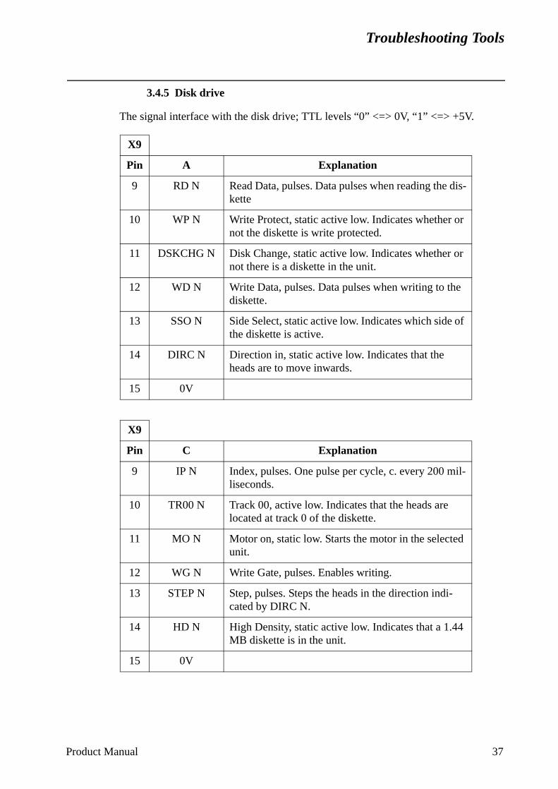
Troubleshooting Tools
3.4.5 Disk drive
The signal interface with the disk drive; TTL levels “0” <=> 0V, “1” <=> +5V.
X9
Pin A Explanation
9 RD N Read Data, pulses. Data pulses when reading the dis-kette
10 WP N Write Protect, static active low. Indicates whether or not the diskette is write protected.
11 DSKCHG N Disk Change, static active low. Indicates whether or not there is a diskette in the unit.
12 WD N Write Data, pulses. Data pulses when writing to the diskette.
13 SSO N Side Select, static active low. Indicates which side of the diskette is active.
14 DIRC N Direction in, static active low. Indicates that the heads are to move inwards.
15 0V
X9
Pin C Explanation
9 IP N Index, pulses. One pulse per cycle, c. every 200 mil-liseconds.
10 TR00 N Track 00, active low. Indicates that the heads are located at track 0 of the diskette.
11 MO N Motor on, static low. Starts the motor in the selected unit.
12 WG N Write Gate, pulses. Enables writing.
13 STEP N Step, pulses. Steps the heads in the direction indi-cated by DIRC N.
14 HD N High Density, static active low. Indicates that a 1.44 MB diskette is in the unit.
15 0V
Product Manual 37
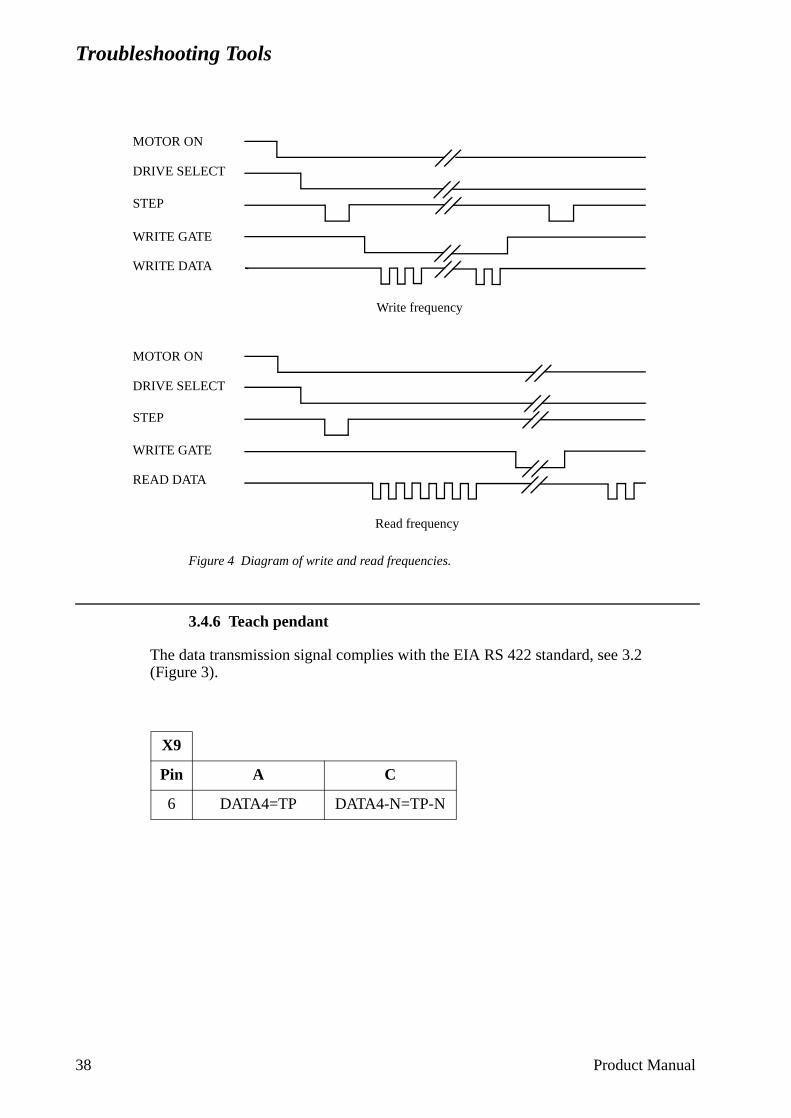
Troubleshooting Tools
Figure 4 Diagram of write and read frequencies.
3.4.6 Teach pendant
The data transmission signal complies with the EIA RS 422 standard, see 3.2(Figure 3).
X9
Pin A C
6 DATA4=TP DATA4-N=TP-N
Write frequency
Read frequency
MOTOR ON
WRITE DATA
MOTOR ON
DRIVE SELECT
STEP
WRITE GATE
READ DATA
WRITE GATE
STEP
DRIVE SELECT
38 Product Manual
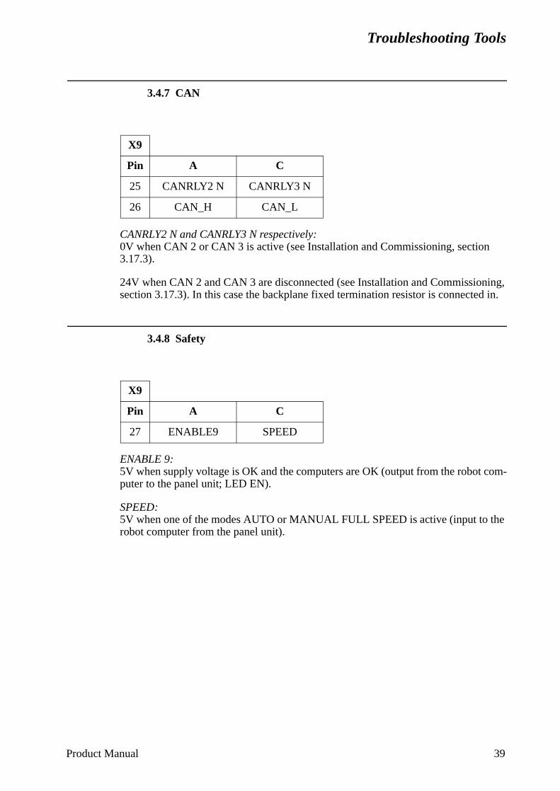
Troubleshooting Tools
3.4.7 CAN
CANRLY2 N and CANRLY3 N respectively:0V when CAN 2 or CAN 3 is active (see Installation and Commissioning, section 3.17.3).
24V when CAN 2 and CAN 3 are disconnected (see Installation and Commissioning, section 3.17.3). In this case the backplane fixed termination resistor is connected in.
3.4.8 Safety
ENABLE 9: 5V when supply voltage is OK and the computers are OK (output from the robot com-puter to the panel unit; LED EN).
SPEED: 5V when one of the modes AUTO or MANUAL FULL SPEED is active (input to the robot computer from the panel unit).
X9
Pin A C
25 CANRLY2 N CANRLY3 N
26 CAN_H CAN_L
X9
Pin A C
27 ENABLE9 SPEED
Product Manual 39

Troubleshooting Tools
40 Product Manual
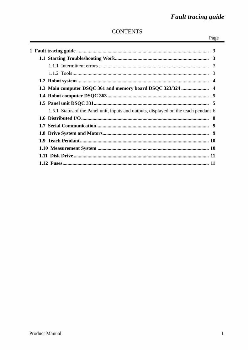
Fault tracing guide
CONTENTSPage
1 Fault tracing guide .......................................................................................................... 3
1.1 Starting Troubleshooting Work........................................................................... 3
1.1.1 Intermittent errors ........................................................................................ 3
1.1.2 Tools............................................................................................................. 3
1.2 Robot system ......................................................................................................... 4
1.3 Main computer DSQC 361 and memory board DSQC 323/324 ...................... 4
1.4 Robot computer DSQC 363 ................................................................................. 5
1.5 Panel unit DSQC 331............................................................................................ 5
1.5.1 Status of the Panel unit, inputs and outputs, displayed on the teach pendant 6
1.6 Distributed I/O...................................................................................................... 8
1.7 Serial Communication.......................................................................................... 9
1.8 Drive System and Motors..................................................................................... 9
1.9 Teach Pendant....................................................................................................... 10
1.10 Measurement System ......................................................................................... 10
1.11 Disk Drive ............................................................................................................ 11
1.12 Fuses..................................................................................................................... 11
Product Manual 1

Fault tracing guide
2 Product Manual
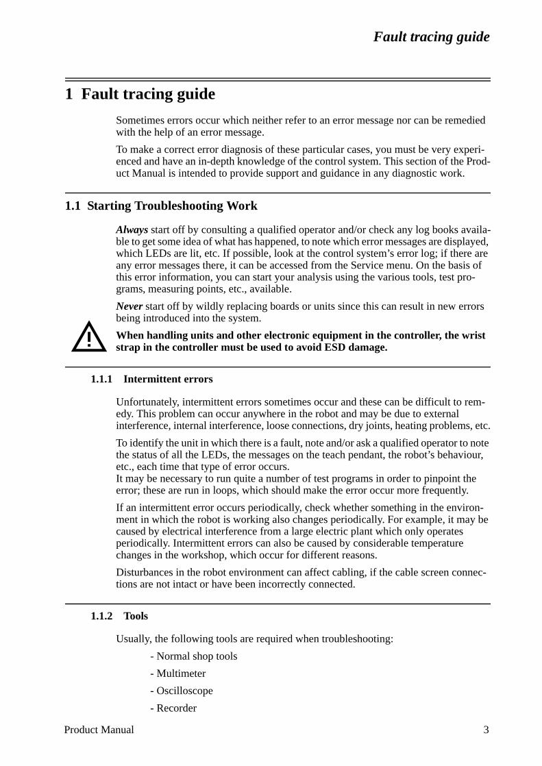
Fault tracing guide
sis of
o-
rs
em-
s, etc.
note viour,
he .
n-y be
nec-
Product Manual 3
1 Fault tracing guide
Sometimes errors occur which neither refer to an error message nor can be remedied with the help of an error message.
To make a correct error diagnosis of these particular cases, you must be very experi-enced and have an in-depth knowledge of the control system. This section of the Prod-uct Manual is intended to provide support and guidance in any diagnostic work.
1.1 Starting Troubleshooting Work
Always start off by consulting a qualified operator and/or check any log books availa-ble to get some idea of what has happened, to note which error messages are displayed, which LEDs are lit, etc. If possible, look at the control system’s error log; if there areany error messages there, it can be accessed from the Service menu. On the bathis error information, you can start your analysis using the various tools, test prgrams, measuring points, etc., available.
Never start off by wildly replacing boards or units since this can result in new errobeing introduced into the system.
When handling units and other electronic equipment in the controller, the wrist strap in the controller must be used to avoid ESD damage.
1.1.1 Intermittent errors
Unfortunately, intermittent errors sometimes occur and these can be difficult to redy. This problem can occur anywhere in the robot and may be due to external interference, internal interference, loose connections, dry joints, heating problem
To identify the unit in which there is a fault, note and/or ask a qualified operator tothe status of all the LEDs, the messages on the teach pendant, the robot’s behaetc., each time that type of error occurs.It may be necessary to run quite a number of test programs in order to pinpoint terror; these are run in loops, which should make the error occur more frequently
If an intermittent error occurs periodically, check whether something in the enviroment in which the robot is working also changes periodically. For example, it macaused by electrical interference from a large electric plant which only operates periodically. Intermittent errors can also be caused by considerable temperaturechanges in the workshop, which occur for different reasons.
Disturbances in the robot environment can affect cabling, if the cable screen contions are not intact or have been incorrectly connected.
1.1.2 Tools
Usually, the following tools are required when troubleshooting:
- Normal shop tools
- Multimeter
- Oscilloscope
- Recorder

Fault tracing guide
ows it read
her rd is
r.
n the ress,
neous
e:
4 Product Manual
1.2 Robot system
In this instance the robot system means the entire robot (controller + manipulator) and process equipment.
Errors can occur in the form of several different errors where it is difficult to localise one particular error, i.e. where it is not possible to directly pinpoint the unit that caused the problem. For example, if the system cannot be cold-started, this may be due to sev-eral different errors (the wrong diskette, a computer fault, etc.).
1.3 Main computer DSQC 361 and memory board DSQC 323/324
The main computer, which is connected to the VME bus and the local bus of the mem-ory board, looks after the higher-level administrative work in the control system. Under normal operating conditions, all diagnostic monitoring is controlled by the main com-puter. At start-up, irrespective of whether a cold or warm start is performed, the robot computer releases the main computer when the robot computer’s diagnostics alland, following this, the main computer takes over the control of the system. The and write memories of the main computer are battery-backed.
If the red LEDs on the main computer light up (or do not turn off at initialisation), eita critical system failure has occurred or the main computer board or memory boafaulty.
The memory board is an extension of the main computer memory.
The memory board has a LED, F, which is lit and turned off by the main compute
If there is a memory error on one of these boards, an error code will be shown odisplay, T1047 or T2010. These error codes also include a field called the At addwhich in turn contains an hexadecimal code that indicates on which board the erromemory circuit is located.
When the error is in the main computer, the hexadecimal code is in the following rang
0 X 000000 - 0 X 7FFFFF
When the error is in the memory board, the code is above 0 X 800 000.

Fault tracing guide
nica-rm m is
, the ve
error
tus is
lit r easy
1.4 Robot computer DSQC 363
The robot computer, which controls the system’s I/O, axis control, serial commution and teach pendant communication, is the first unit to start after a cold or wastart. The red LED on the front of the board goes off immediately when the systereset and goes on again if an error is detected in the tests. As mentioned aboverobot computer releases the main computer when the preliminary diagnostics hagiven the go ahead-signal.
The read and write memories of the robot computer are battery-backed.
If the system does not start at all, and the LED on the robot computer goes on, theis probably in the robot computer.
1.5 Panel unit DSQC 331
The DSQC 331 Panel unit controls and monitors the dual operation chain. Its staalso indicated by LEDs at the upper part of the unit.
Over temperature of the motors is monitored by PTC inputs to the board.
LED indications for DSQC 331
The LEDs are very useful when trying to locate errors in the operation chain. UnLEDs indicate the whereabouts of an error in the operation chain, making the erroto locate in the system circuit diagram.
Marking Colour Meaning
EN Green Indicates “go ahead” from the control system
MSNSES 1 and 2GS 1 and 2AS 1 and 2
Green/redGreen/redYellowYellowYellow
Module status, normally green, see also section 1.6Network status, normally green, see also section 1.6EMERGENCY STOP, chain 1 and 2 closedGENERAL STOP switch, chain 1 and 2 closedAUTO STOP switch, chain 1 and 2 closed
Product Manual 5
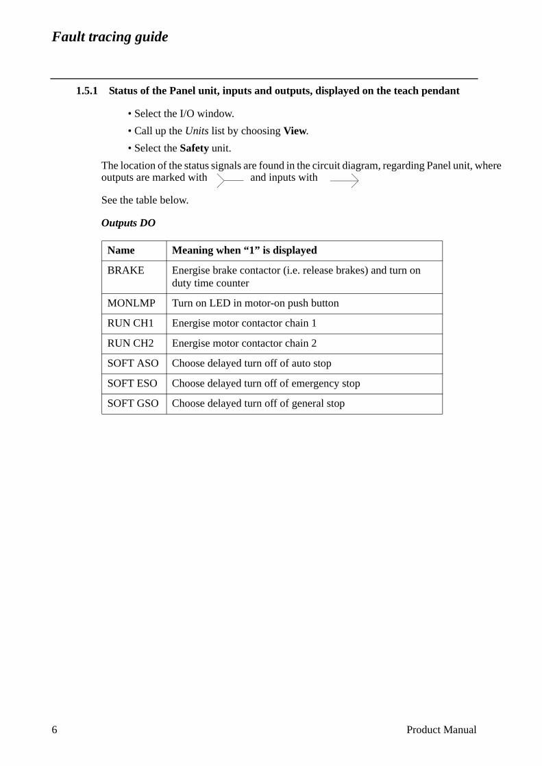
Fault tracing guide
where
1.5.1 Status of the Panel unit, inputs and outputs, displayed on the teach pendant
• Select the I/O window.
• Call up the Units list by choosing View.
• Select the Safety unit.
The location of the status signals are found in the circuit diagram, regarding Panel unit, outputs are marked with and inputs with
See the table below.
Outputs DO
Name Meaning when “1” is displayed
BRAKE Energise brake contactor (i.e. release brakes) and turn on duty time counter
MONLMP Turn on LED in motor-on push button
RUN CH1 Energise motor contactor chain 1
RUN CH2 Energise motor contactor chain 2
SOFT ASO Choose delayed turn off of auto stop
SOFT ESO Choose delayed turn off of emergency stop
SOFT GSO Choose delayed turn off of general stop
6 Product Manual
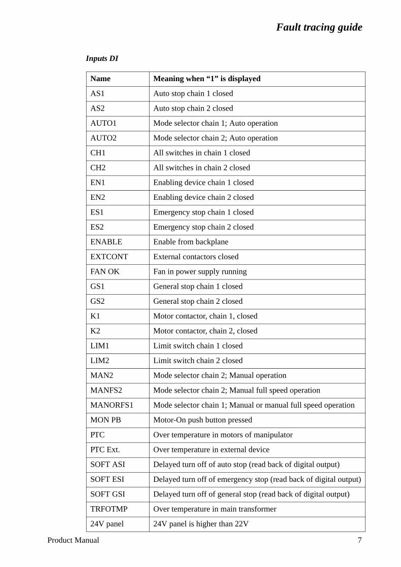
Fault tracing guide
Inputs DI
Name Meaning when “1” is displayed
AS1 Auto stop chain 1 closed
AS2 Auto stop chain 2 closed
AUTO1 Mode selector chain 1; Auto operation
AUTO2 Mode selector chain 2; Auto operation
CH1 All switches in chain 1 closed
CH2 All switches in chain 2 closed
EN1 Enabling device chain 1 closed
EN2 Enabling device chain 2 closed
ES1 Emergency stop chain 1 closed
ES2 Emergency stop chain 2 closed
ENABLE Enable from backplane
EXTCONT External contactors closed
FAN OK Fan in power supply running
GS1 General stop chain 1 closed
GS2 General stop chain 2 closed
K1 Motor contactor, chain 1, closed
K2 Motor contactor, chain 2, closed
LIM1 Limit switch chain 1 closed
LIM2 Limit switch chain 2 closed
MAN2 Mode selector chain 2; Manual operation
MANFS2 Mode selector chain 2; Manual full speed operation
MANORFS1 Mode selector chain 1; Manual or manual full speed operation
MON PB Motor-On push button pressed
PTC Over temperature in motors of manipulator
PTC Ext. Over temperature in external device
SOFT ASI Delayed turn off of auto stop (read back of digital output)
SOFT ESI Delayed turn off of emergency stop (read back of digital output)
SOFT GSI Delayed turn off of general stop (read back of digital output)
TRFOTMP Over temperature in main transformer
24V panel 24V panel is higher than 22V
Product Manual 7
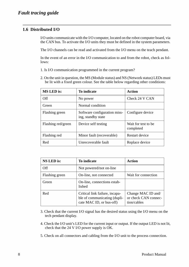
Fault tracing guide
8
t,
on.
1.6 Distributed I/O
I/O units communicate with the I/O computer, located on the robot computer board, via the CAN bus. To activate the I/O units they must be defined in the system parameters.
The I/O channels can be read and activated from the I/O menu on the teach pendant.
In the event of an error in the I/O communication to and from the robot, check as fol-lows:
1. Is I/O communication programmed in the current program?
2. On the unit in question, the MS (Module status) and NS (Network status) LEDs must be lit with a fixed green colour. See the table below regarding other conditions:
3. Check that the current I/O signal has the desired status using the I/O menu on the tech pendant display.
4. Check the I/O unit’s LED for the current input or output. If the output LED is not licheck that the 24 V I/O power supply is OK.
5. Check on all connectors and cabling from the I/O unit to the process connecti
MS LED is: To indicate Action
Off No power Check 24 V CAN
Green Normal condition
Flashing green Software configuration miss-ing, standby state
Configure device
Flashing red/green Device self testing Wait for test to be completed
Flashing red Minor fault (recoverable) Restart device
Red Unrecoverable fault Replace device
NS LED is: To indicate Action
Off Not powered/not on-line
Flashing green On-line, not connected Wait for connection
Green On-line, connections estab-lished
Red Critical link failure, incapa-ble of communicating (dupli-cate MAC ID, or bus-off)
Change MAC ID and/or check CAN connec-tion/cables
Product Manual
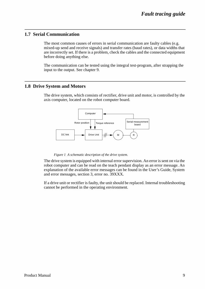
Fault tracing guide
ystem
ting
1.7 Serial Communication
The most common causes of errors in serial communication are faulty cables (e.g. mixed-up send and receive signals) and transfer rates (baud rates), or data widths that are incorrectly set. If there is a problem, check the cables and the connected equipment before doing anything else.
The communication can be tested using the integral test-program, after strapping the input to the output. See chapter 9.
1.8 Drive System and Motors
The drive system, which consists of rectifier, drive unit and motor, is controlled by the axis computer, located on the robot computer board.
Figure 1 A schematic description of the drive system.
The drive system is equipped with internal error supervision. An error is sent on via the robot computer and can be read on the teach pendant display as an error message. An explanation of the available error messages can be found in the User’s Guide, Sand error messages, section 3, error no. 39XXX.
If a drive unit or rectifier is faulty, the unit should be replaced. Internal troubleshoocannot be performed in the operating environment.
Computer
DC link Drive Unit M R
Serial measurement board
Torque referenceRotor position
Product Manual 9
Fault tracing guide
ated. ro-ou try to
Main-
stops
lver e 7th rce of
1.9 Teach Pendant
The teach pendant communicates with the robot computer via a cable. This cable is also used for the +24 V supply and the dual operation chain.
If the display is not illuminated, try first adjusting the contrast, and if this does not help check the 24 V power supply.
Communication errors between the teach pendant and the I/O computer are indicated by an error message on the teach pendant.
For measuring points for the teach pendant communication signals, see chapter 9.
1.10 Measurement System
The measurement system comprises an axis computer, one or more serial measurement boards and resolvers. The serial measurement board is used to collect resolver data. The board is supplied from 24 V SYS via a fuse on the back plane. The board is located in the manipulator and is battery-backed. Communication with the axis computer takes place across a differential serial link (RS 485).
The measurement system contains information on the position of the axes and this information is continuously updated during operation. If the resolver connections are disconnected or if the battery goes dead after the robot has been stationary for a long period of time, the manipulator’s axis positions will not be stored and must be updThe axis positions are updated by manually jogging the manipulator to the synchnised position and then, using the teach pendant, setting the counters to zero. If yto start program execution without doing the above, the system will give an alarmindicate that the system is not calibrated.
Measuring points for the measurement system are located on the backplane, X9tenance plug, see chapter 9 for more detailed information.
Note that it is necessary to re-calibrate after the resolver lines have been disconnected. This applies even if the manipulator axes have not been moved.
Transmission errors are detected by the system’s error control, which alerts and program execution if necessary.
Common causes of errors in the measurement system are line breakdown, resoerrors and measurement board interference. The latter type of error relates to thaxis, which has its own measurement board. If it is positioned too close to a souinterference, there is a risk of an error.
10 Product Manual
Fault tracing guide
can be
drive
9. mpare
upplies A and
e is no
icated
the
tion
1.11 Disk Drive
The disk drive is controlled by the I/O computer via a flat cable. The power is supplied by a separate cable.
Common types of error are read and write errors, generally caused by faulty diskettes. In the event of a read and/or write error, format a new, high quality diskette in the robot and check to see whether the error disappears. If the error is still present, the disk drive will probably have to be replaced. However, check the flat cable first.
NB: Never use diskettes without a manufacturer’s mark. Unmarked, cheap diskettes of very poor quality.
If the disk drive is completely dead, check the supply voltage connection to the disk to see that it is +5 V, before replacing the drive.
Measuring points are available on the backplane: X9 Maintenance plug, see chapterWhen replacing the disk drive, check that the strapping is set correctly on the unit. Cowith the faulty drive being replaced.
1.12 Fuses
There is one automatic three-phase 20 A fuse that supplies the DC-link in the MOTORS ON state, on the transformer. There is also a automatic three-phase 10 A fuse that sthe power supply unit. There are also two fuses for customer AC supplies, one 3.15 one 6.3 A.
The backplane has four PTC resistance fuses:
- Serial measurement board 1
- Serial measurement board 2
- CAN2, manipulator I/O
- CAN3, external I/O
The fuses protect against 24 V short-circuits and return to the normal state when therlonger a risk of short-circuiting.
The panel unit has one PTC fuse to protect the motor on chains. An open fuse is indon the teach pendant, see Status of the Panel unit, inputs and outputs, displayed on the teach pendant side 6, 24 panel.
The cabling from customer 24 V supply is protected by a 2A fuse on terminal XT31 inupper compartment of the controller.
Note that the power supply unit DSQC 374 is provided with a short circuit energy limitawhich makes the fuse unnecessary.
Product Manual 11

Fault tracing guide
12 Product Manual
This chapter is not included in the On-line Manual.
Click on the Main menu button below to continue to the front page.
Main menu
ABB Flexible Automation AB
Repairs
CONTENTSPage
1 General Description ........................................................................................................ 3
1.1 Document Guidance ............................................................................................... 5
1.2 Caution.................................................................................................................... 6
1.3 Mounting Instructions for Bearings and Seals ....................................................... 6
1.3.1 Bearings ....................................................................................................... 6
1.3.2 Seals ............................................................................................................. 7
1.4 Instructions for Tightening Screw Joints................................................................ 9
1.5 Tightening Torques ................................................................................................. 10
1.5.1 Screws with slotted or cross recessed head.................................................. 10
1.5.2 Screws with hexagon socket head................................................................ 10
2 Axis 1 ............................................................................................................................... 11
2.1 Replacement of motor ............................................................................................ 11
2.2 Cabling axis 1 ......................................................................................................... 12
2.3 Replacing the gearbox ............................................................................................ 14
2.4 Dismounting joint bearing ...................................................................................... 15
2.5 Dismounting cooling axis 1.................................................................................... 16
3 Axis 2 ................................................................................................................................ 17
3.1 Replacing motor ..................................................................................................... 17
3.2 Replacing the gearbox ............................................................................................ 18
3.3 Replacing lower arm............................................................................................... 19
3.4 Replacing bearing in lower arm.............................................................................. 20
3.5 Dismounting balancing unit.................................................................................... 21
3.6 Replacing guiding ring, balancing unit................................................................... 23
3.7 Replacing bearings, balancing unit......................................................................... 24
3.8 Dismounting cables, lower arm/upper arm............................................................. 25
4 Axis 3 ................................................................................................................................ 27
4.1 Replacing motor ..................................................................................................... 27
4.2 Replacing gearbox .................................................................................................. 28
4.3 Dismounting parallel arm ....................................................................................... 29
4.4 Replacing parallel bar with bearings ...................................................................... 29
4.5 Dismounting upper arm, complete ......................................................................... 30
4.6 Dismounting arm extender ..................................................................................... 32
5 Pushbutton unit for release of brakes ........................................................................... 33
5.1 Replacing pushbutton unit ...................................................................................... 33
6 Axis 4 ................................................................................................................................ 35
6.1 Replacing motor ..................................................................................................... 35
6.2 Replacing and adjusting intermediate gear............................................................. 36
Product Manual IRB 6400 1
Repairs
CONTENTSPage
6.3 Replacing final gear................................................................................................ 37
6.4 Dismounting tube shaft, upper arm ........................................................................ 38
6.5 Replacing seals and bearings, upper arm ............................................................... 39
7 Wrist, axes 5 and 6 .......................................................................................................... 41
7.1 Dismounting the wrist ............................................................................................ 41
7.2 Dismounting cabling, axis 5 ................................................................................... 42
7.3 Dismounting cabling, axis 6 ................................................................................... 42
7.4 Replacing motor axis 5........................................................................................... 43
7.5 Replacing motor/gear axis 6................................................................................... 44
7.6 Checking play in axes 5 and 6................................................................................ 45
7.7 Adjusting play in axis 5.......................................................................................... 47
7.7.1 Adjusting the intermediate gear unit............................................................ 48
7.7.2 Adjusting the intermediate gear unit bearings ............................................. 48
8 Motor units ...................................................................................................................... 51
8.1 General ................................................................................................................... 51
8.2 Checking brake performance.................................................................................. 52
9 Calibration....................................................................................................................... 53
9.1 General ................................................................................................................... 53
9.2 Calibration procedure ............................................................................................. 53
9.3 Setting the calibration marks on the manipulator................................................... 59
9.4 Checking the calibration position........................................................................... 62
9.5 Alternative calibration positions ............................................................................ 62
9.6 Calibration equipment ............................................................................................ 64
10 Special Tools List........................................................................................................... 65
2 Product Manual IRB 6400
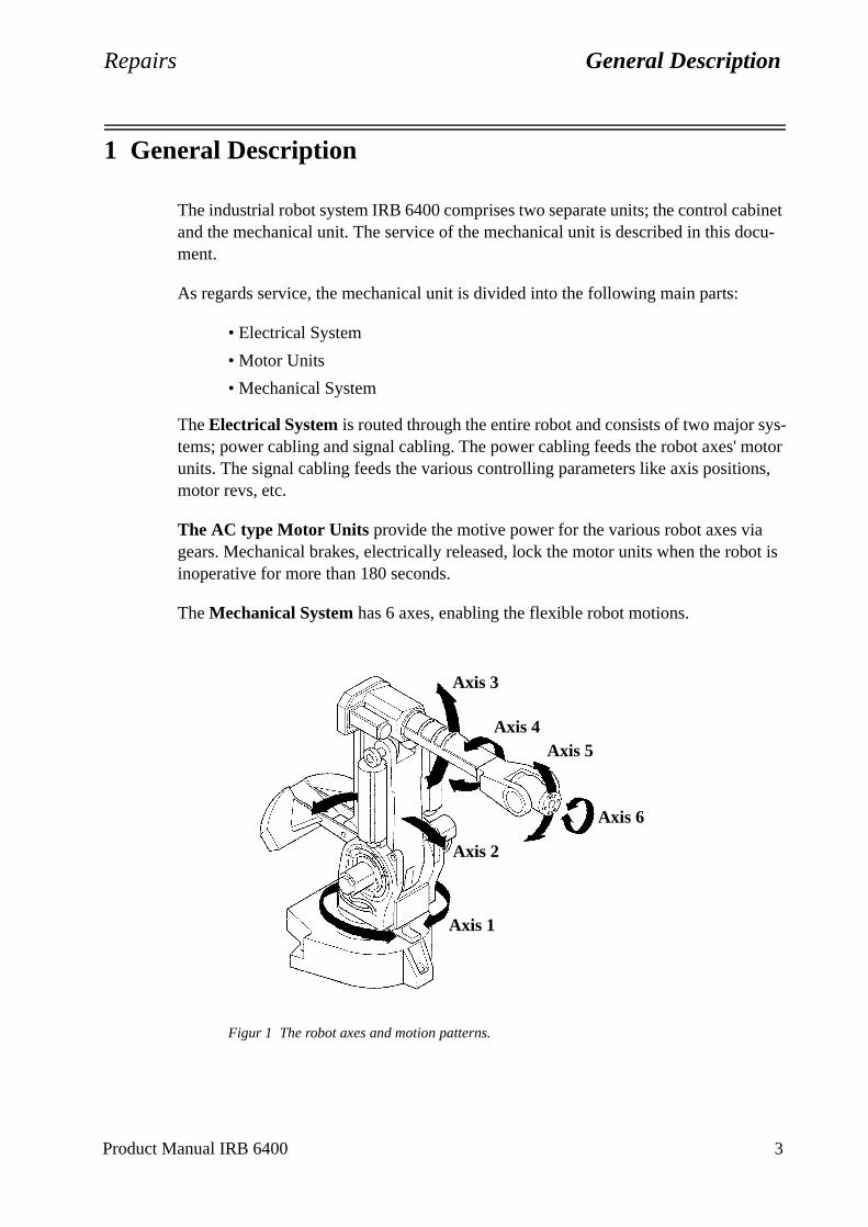
Repairs General Description
sys-motor ns,
ot is
1 General Description
The industrial robot system IRB 6400 comprises two separate units; the control cabinet and the mechanical unit. The service of the mechanical unit is described in this docu-ment.
As regards service, the mechanical unit is divided into the following main parts:
• Electrical System
• Motor Units
• Mechanical System
The Electrical System is routed through the entire robot and consists of two major tems; power cabling and signal cabling. The power cabling feeds the robot axes' units. The signal cabling feeds the various controlling parameters like axis positiomotor revs, etc.
The AC type Motor Units provide the motive power for the various robot axes via gears. Mechanical brakes, electrically released, lock the motor units when the robinoperative for more than 180 seconds.
The Mechanical System has 6 axes, enabling the flexible robot motions.
Figur 1 The robot axes and motion patterns.
Axis 2
Axis 3
Axis 4Axis 5
Axis 6
Axis 1
Product Manual IRB 6400 3
General Description Repairs
in
in
5 and
is he pply tions
with
n and
Axis No. 1 rotates the robot via a frame.
Axis No. 2, which provides the lower arm´s reciprocating movement, is supportedthe frame. The Lower Arm forms together with the Parallel Arm and the Parallel Bracket, a parallelogram against the Upper Arm. The Parallel Bracket is mountedbearings in the Parallel Arm and in the Upper Arm.
Axis No. 3 provides elevation of the robot's upper arm.
Axis No. 4, located in the Upper Arm, provides a rotary motion of the Upper Arm.
The Wrist is bolted to the Upper Arm's forward end and comprises the axes Nos. 6. The latter axes form a cross.
Axis No. 5 provides a tilting motion and Axis No. 6 a turning motion. A connectionarranged for various customer tools at the front end of the wrist in the Turn Disc. Ttool (or manipulator) can be equipped with pneumatic control via an external air su(option). The signals to/from the tool can be supplied via internal customer connec(option).
The Control Cabinet must be switched off during all service work on the robot! Before doing any work on the robot measurement system (measurement board, cabling), the accumulator power supply must always be disconnected.
When service work is finished, the calibration position should always be checked the system disc.
The Brake Release Unit should be connected as indicated in Section 7, InstallatioCommissioning, to enable movements of the axes.
Special care must be taken when the brakes are operated manually. This applies particularly when the robot is started up, either for the first time or after a stop-page. The safety instructions in the Programming Manual must be complied with at all times.
4 Product Manual IRB 6400
Repairs General Description
expe-ive to
; or board
g; other car-
sump-ver,
tifi-po-
in the ce is ber is s)
evant
1.1 Document Guidance
The subsequent chapters describe the type of service work that can be carried out by the Customer´s own service staff on site. Certain types of work, requiring special rience or special aids, are not dealt with in this manual. In such cases, the defectmodule or component should be replaced on site. The faulty item should be sent ABB Flexible Automation for service.
Calibration. Recalibration of the robot may have to be carried out after replacing mechanical unit parts or when the motor and feedback unit have been separatedwhen a resolver error has occurred or the power supply between a measurementand resolver has been interrupted. The procedure is described in detail in Chapter 9, Calibration.
IMPORTANT! When work is done on the robot signal cabling, this may result in the robot moving to incorrect positions.
After doing such work, it is important that the robot calibration position is checked as described in Chapter 9.4, Checking the calibration position. If a cali-bration fault is discovered, the robot must be recalibrated as described in Chapter 9, Calibration.
Tools. Two types of tools are required for various service jobs involving dismantlinon the one hand, conventional tools like socket and ratchet spanners, etc.; on thehand, special tools may be necessary, depending on what type of service is beingried out. The conventional tools are not dealt with in this manual, based on the astion that the service personnel have sufficient technical basic competence. Howeservice work requiring the use of special tools is described in this manual.
Exploded views. In the Spare Parts chapter of this manual, there are a number of exploded view foldouts illustrating the robot parts, intended to facilitate quick idencation of both the type of service required and the composition of the various comnents. The parts are item numbered on the foldouts. The foldouts are referred to Manual text within "arrow heads" (< >) as exploded view numbers. Where referenmade to foldouts, other than those specified in the paragraph title, the foldout numincluded in the item number reference, for example <5/19> or <10:2/5>, the digit(before the slash referring to the foldout number.
Numbers in brackets ( ) refer to figures in the text.
The foldouts also include information such as article number, designation and reldata.
N.B. This manual is not to be considered as a substitute for a proper training course. This document is intended for use after the course has been completed.
Product Manual IRB 6400 5
General Description Repairs
1.2 Caution
The mechanical unit contains several parts which are too heavy to lift manually. As these parts must be moved with precision during any maintenance and repair work, it is important to have a suitable lifting device available.
The robot should always be switched to MOTORS OFF before allowing anyone to enter its working space.
1.3 Mounting Instructions for Bearings and Seals
1.3.1 Bearings
1. Let a new bearing remain in its wrapping until it is time for fitting, to avoid contamina-tion of the bearing.
2. Ensure that all parts included in the bearing fitting are free from burrs, grindingwaste and other contamination. Cast components must be free from foundry sand.
3. Bearing rings, inner rings and roller elements must under no circumstances be subjected to direct impact. Also, the roller elements must not be exposed to anystresses during the assembly work.
Tapered Bearings
4. The bearing should be tensioned gradually until the recommended pre-tension is achieved.
5. It is important to note that the roller elements must be rotated a specified number of turns before pre-tensioning is carried out, and also rotated during the pre-tensioning sequence.
6. The above procedure must be carried out to enable the roller elements to adjust to the correct position against the race flange. Also, it is important that the bearing is properly aligned, as this will directly affect the lifespan of the bearing.
Greasing Bearings
7. The bearing must be greased after fitting. The main reason for this is the requirement for cleanliness. Good quality lubricating grease should be used, for example 3HAB 3537-1.
8. Grooved ball bearings should be filled with grease from both sides.
9. Tapered roller bearings and axial needle bearings shall be greased in the split condition.
6 Product Manual IRB 6400
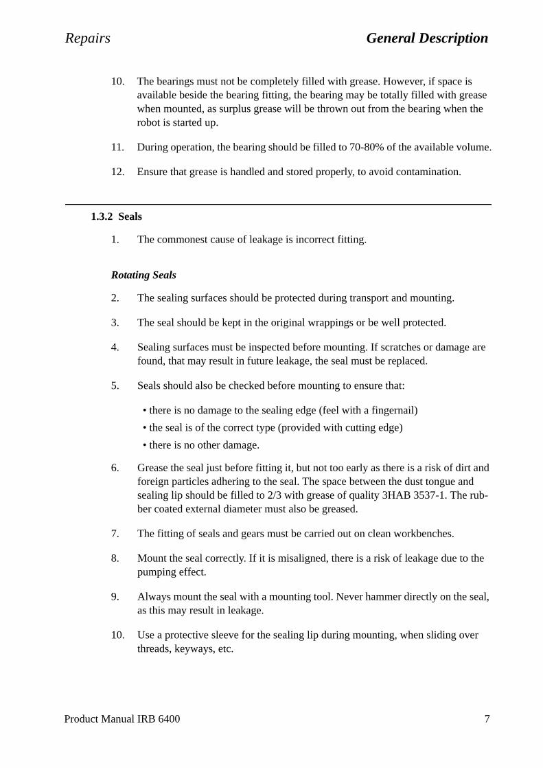
Repairs General Description
t and nd b-
the
eal,
er
10. The bearings must not be completely filled with grease. However, if space is available beside the bearing fitting, the bearing may be totally filled with grease when mounted, as surplus grease will be thrown out from the bearing when the robot is started up.
11. During operation, the bearing should be filled to 70-80% of the available volume.
12. Ensure that grease is handled and stored properly, to avoid contamination.
1.3.2 Seals
1. The commonest cause of leakage is incorrect fitting.
Rotating Seals
2. The sealing surfaces should be protected during transport and mounting.
3. The seal should be kept in the original wrappings or be well protected.
4. Sealing surfaces must be inspected before mounting. If scratches or damage are found, that may result in future leakage, the seal must be replaced.
5. Seals should also be checked before mounting to ensure that:
• there is no damage to the sealing edge (feel with a fingernail)
• the seal is of the correct type (provided with cutting edge)
• there is no other damage.
6. Grease the seal just before fitting it, but not too early as there is a risk of dirforeign particles adhering to the seal. The space between the dust tongue asealing lip should be filled to 2/3 with grease of quality 3HAB 3537-1. The ruber coated external diameter must also be greased.
7. The fitting of seals and gears must be carried out on clean workbenches.
8. Mount the seal correctly. If it is misaligned, there is a risk of leakage due to pumping effect.
9. Always mount the seal with a mounting tool. Never hammer directly on the sas this may result in leakage.
10. Use a protective sleeve for the sealing lip during mounting, when sliding ovthreads, keyways, etc.
Product Manual IRB 6400 7
General Description Repairs
Flange Seals and Static Seals
11. Check the flange surfaces. They must be even and free from pores. It is easy to check flatness using a gauge on the fastened joint (without sealing compound).
12. Differences in surface level or the presence of burrs due to incorrect machining are not permissible. If flange surfaces are defective, the parts must not to be used, because leakage could result.
13. The surfaces must be properly cleaned in accordance with ABB Flexible Automation recommendations.
14. Distribute the sealing compound evenly over the surface, preferably with a brush.
15. Tighten the screws evenly when fastening the flange joint.
O-rings
16. Check the O-ring grooves. The grooves must be geometrically correct and free from pores and contamination.
17. Check the O-ring with regard to surface defects, burrs, shape accuracy, etc.
18. Ensure that the correct O-ring size is used.
19. Tighten the screws evenly when assembling.
20. Defective O-rings and O-ring grooves must not be used.
21. Fitting defective parts will result in leakage. Grease the O-ring with lubricant 3HAB 3537-1 before mounting.
8 Product Manual IRB 6400
Repairs General Description
1.4 Instructions for Tightening Screw Joints
General
It is of the utmost importance that all screw joints be tightened with the correct torque.
Application
The following tightening torques are to be used for all screw joints in metallic materials unless otherwise specified in the text.
These instructions do not apply to screw joints comprising soft or brittle materials.
For screws with a higher property class than 8.8, the data for 8.8 must be used unless otherwise specified.
Screws treated with Gleitmo (lubricated)
When handling screws treated with Gleitmo, protective gloves of nitrile rubber type should be used.
Screws treated with Gleitmo can be unscrewed and screwed in again 3-4 times before the slip coating disappears. Screws can also be treated with Molycote 1000.
When screwing in new screws that are not Gleitmo treated, these should first be lubri-cated with Molycote 1000 and tightened to the specified torque.
Assembly
Lubrication with molybdenum disulphide grease (Molycote 1000) should only be used when specified in the text.
Screws lubricated with Molycote 1000 and then torque tightened, should also to be lubricated between the washer and the head of the screw.
Screws with dimension M8 or larger should be tightened with a torque-wrench, if pos-sible.
Screws with dimension M6 or smaller may be tightened to the correct torque using tools without torque indication, by personnel with adequate mechanical training and instruction.
Product Manual IRB 6400 9
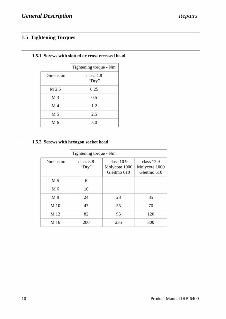
General Description Repairs
1.5 Tightening Torques
1.5.1 Screws with slotted or cross recessed head
1.5.2 Screws with hexagon socket head
Tightening torque - Nm
Dimension class 4.8“Dry”
M 2.5 0.25
M 3 0.5
M 4 1.2
M 5 2.5
M 6 5.0
Tightening torque - Nm
Dimension class 8.8“Dry”
class 10.9Molycote 1000Gleitmo 610
class 12.9Molycote 1000Gleitmo 610
M 5 6
M 6 10
M 8 24 28 35
M 10 47 55 70
M 12 82 95 120
M 16 200 235 300
10 Product Manual IRB 6400
Repairs Axis 1
2 Axis 1
2.1 Replacement of motor
Refer to foldout no. 1:1.
Dismounting:
Be careful not to tap or hit the shaft axially, nor displace the shaft axially in any way, as this could give rise to an incorrect air gap in the brake.
1. Remove the cover in the frame between axes 2 and 3.
2. Unscrew the 3 screws on the top of motor 1. Remove the cover.
3. Unscrew the 4 cable inlet cover screws.
4. Disconnect connectors R2.MP1 and R2.FB1 in the motor.
5. Unscrew the motor flange, 4 screws <9>. Use two screws in the threaded holes (M8) on the motor flange, to push out the motor from its attachment.
6. Loosen screw <15>, fit a 150 mm screw, and pull off the pinion with the help of a puller.
Mounting:
7. Mount a threaded pin in the motor shaft and press the gear on to the shaft with a nut and washer. Mount screw <15> through the gear, torque 70 Nm, Loctite 243.
Axial force through the bearings in the motor is prohibited.
8. Ensure that assembly surfaces are clean and unscratched.
9. Apply sealing liquid Permatex 3 under the motor flange.
10. Mount the motor, grease screw <9> with Molycote 1000 and tighten with a torque of 50 Nm.
11. Calibrate the robot as described in Chapter 9, Calibration.
Tightening torque:
Screws for motor, item 9: 50 Nm.
Screw for motor gear, item 15: 70 Nm.
Product Manual IRB 6400 11
Axis 1 Repairs
2.2 Cabling axis 1
Dismounting:
Refer to foldout 1:1, 1:3 and 2.
1. Place axis 1 in calibration position 0. Shut down the robot system with the mains switch.
2. Loosen the control cable connectors in the robot base.
3. Loosen the covers <1:1/21, 22> on base cabling from the base by unscrewing screws <1:1/18>.
4. Loose the support rail <2/3>, screws <2/6> and remove it forward in a location away from the base cabling as much as possible.Do not remove the screws!
5. Loose the base cabling at the bottom of the base <2/1>.Do not remove the screws!
6. Tighten all screws <2/6> again after that the cabling is removed.
To avoid that the base plate <2/2> rotates and to make dismounting and mounting of the cabling easier.
7. Take out the cover <1:1/22> and disconnect the earth wire from the contact plate in the base.
8. Loose the base cabling at the frame, screws <1:3/25>. The screws must be removed.
9. Loose the cover over axis 1 motor, the brake release unit and the serial measure-ment board.
Caution!The seriel measurement board is an electrostatic sensitive device.Use wrist strap.
12 Product Manual IRB 6400
Repairs Axis 1
10. Disconnect the contacts to the base cabling in the frame:
R2.SMB(X2)R2.CP (only in the case, customer connection)R2.CS (only in the case, customer connection)R2.CB (only in the case, customer connection)R2.MP1R2.MP2R2.MP3R2.MP4R2.MP5-6R2.FAN (connected only for PT or optional)R3.BU1-6(X8)R3.BU1-3(X9)R3.BU4-6 (X10)Air hose (shall be loosened at the nipple on the base and the nipple in the
frame, only in the case, customer connection)
11. Feed the cabling carefully through the hole in the left side of the base.
Mounting:
12. Feed the cable inside the base through the hole on the left side. The robot should be positioned in calibration position 0. Pull the cables through the hole in the frame and pull out connectors to their correct positions.
13. Mount the screws <1:3/25> with washers <1:3/26> which holds the cabling to the frame. Add Loctite 243 and tighten.
14. Connect all contacts inside the frame and at the brake release unit and serial meas-urement board. Mount the brake release unit and serial measurement board, use Loctite 243.
15. Connect the earth wire.
16. Unscrew screws <2/6> approx. 8 mm. See foldout 2.
17. Place the cover <1:1/22> in position.
18. Place the cabling in position on the bottom of the base.
19. Remove screws <2/6>, which keeps the cabling fixed to the bottom of the base, one at the time and add Loctite 243 and tighten it.
20. Mount support rail <2/3>. Add Loctite 243 and tighten.
21. Assembly all covers, use Loctite 243.
Note! All removed straps must be remounted.
Product Manual IRB 6400 13
Axis 1 Repairs
2.3 Replacing the gearbox
Refer to foldout no. 1:1, 3:1 (3:2, S /2.9-120).
Dismounting:
1. Dismount motor and the cabling, as described in Chapter 2.1, Replacement of motor and Chapter 2.2, Cabling axis 1.
2. Disconnect the cables and the air hose that comes through the lower arm, and is connected to the frame.
3. Attach a hoist in existing lifting eye bolts.
For instructions about lifting, see Chapter 7, Installation and Commissioning, depending on which type of robot is to be lifted.
To facilitate dismounting, it is essential that the arm system is evenly balanced. Move the lower arm slightly backwards and allow the upper arm to move down as far as possible, in order to concentrate the centre of gravity as close as possible. If there is any load on the wrist, or any other equipment, the positioning may be affected.
4. Unscrew screws <1:1/43, 45> for the gear. Accessible through holes in the frame.
5. Remove screws <1:1/6> holding the joint bearing.
6. Lift the arm system straight up.
7. Place the arm system on some kind of support.
Make sure that the arm system is properly supported, so that the gearbox can be safely removed.
8. Loosen screws <3:1/6> for the gearbox.
Mounting:
9. Mount two guide pins, M12x200 under the frame, to facilitate mounting of the friction ring and gear.
10. Fit O-ring <3:1/11>, friction ring <3:1/13> and gear <3:1/12>. Apply Molycote 1000 on the screws <3:1/6> and tighten with a torque of 120 Nm.
11. Mount two guide pins, M12x300 in the manipulator base.
12. Mount O-ring <1:1/12> at the bottom in the base.
13. Lift the arm system and then lower it carefully until the joint bearing is just about to enter the bearing seat.
14. Align the holes in the bearing <3:1/2> with the holes in the base, with two screws.
14 Product Manual IRB 6400
Repairs Axis 1
15. Lower the arm system.
16. Apply Loctite 577 on screws <1:1/43, 45>. Do not tighten the screws. Rotate the gear approx. 10 turns (input shaft) forwards and backwards, using the tool 3HAC 0266-1. Tighten first screws <1:1/43> with a torque of 300 Nm and then screws <1:1/45> with a torque of 120 Nm.
Note! The sequence when tightening the screws.
17. Mount screws <1:1/6>, lubricate with Molycote 1000 and tighten with a torque of120 Nm.
18. Mount motor and cabling as described in Chapter 2.1, Replacement of motor and Chapter 2.2, Cabling axis 1.
19. Calibrate the robot as described in Chapter 9, Calibration.
Tightening torque:
Screw joint gear/base, item 43: 300 NmScrew joint gear/base, item 45: 120 NmScrew joint gear/frame, item 3:1/6: 120 NmScrew joint bearing/base, item 1:1/6: 120 Nm
2.4 Dismounting joint bearing
Refer to foldout 3:1 (3:2, S /2.9-120).
Dismounting:
1. Dismount the arm system as described in Chapter 2.3, Replacing the gearbox.
2. Unscrew screws <3> and remove the joint bearing.
Mounting:
3. Apply grease to the bearing seat and push it on with screws <3>. Lubricate screws with Molycote 1000 and tighten with a torque of 120 Nm.
4. Refit the arm system as described in Chapter 2.3, Replacing the gearbox.
Tightening torque:
Screw joint bearing, item 3: 120 Nm.
Product Manual IRB 6400 15
Axis 1 Repairs
2.5 Dismounting cooling axis 1
Refer to foldout 13.
Dismounting:
1. Dismount cover <11> in the frame between axes 2 and 3.
2. Disconnect fan cabling <12>, R2.FAN.
3. Remove the filter holder.
4. Loosen and remove the fan <1>.
Mounting:
5. Mount in reverse order.
16 Product Manual IRB 6400
Repairs Axis 2
3 Axis 2
3.1 Replacing motor
Refer to foldout 4:1, 4:2.
Dismounting:
Be careful not to tap or hit the shaft axially, nor displace the shaft axially in any way, as this could give rise to an incorrect air gap in the brake.
1. Move the lower arm to the position where it is possible to secure the arm with screws, through the holes in the lower fixing points of the balancing springs. Tighten the screws into the lower arm.
2. Unscrew the 3 screws on top of motor 2. Remove the cover.
3. Unscrew the 4 cable inlet cover screws.
4. Disconnect connectors R3.MP2 and R3.FB2 in the motor.
5. Attach a hoist to the motor. The weight of the motor is 17 kg.
6. Loosen the screws <1.31> for the motor.
7. Pull out the motor. (In case of difficulty, use the threaded M8 holes on the motor flange to push the motor out.)
8. Unscrew screw <1.30> and mount a screw with a length of 150 mm and pull off the gear with a puller.
Mounting:
9. Fit a fully threaded pin in the motor shaft and press the gear on to the shaft with a nut and a washer. Mount screw <1.30> through the gear, torque 45 Nm, Loctite 243.
This is to avoid axial force through the bearings in the motor.
10. Ensure that assembly surfaces are clean and unscratched.
11. Mount O-ring <1.28> using some grease.
12. Mount motor, lubricate screws <1.31> with Molycote 1000 and tighten with a torque of 50 Nm.
Do not forget to remove the locking screws in the lower arm!
13. Calibrate the robot as described in Chapter 9, Calibration.
Product Manual IRB 6400 17

Axis 2 Repairs
18 Product Manual IRB 6400
Tightening torque:
Screws for motor, item 1.31: 50 Nm
Screw for gear, item 1.30: 70 Nm
3.2 Replacing the gearbox
Refer to foldout 4:1, 4:2.
Dismounting:
1. Remove motor as in Chapter 3.1, Replacing motor.
2. Unscrew screws <1.38.2> and remove the motor socket <1.38.1>.
3. Mount 2 guide pins, M12, through the gearbox.
4. Loosen the screws <1.5> and <1.7>.
5. Pull the gearbox <1.3> out, suspended on the guide pins.
Mounting:
6. Clean the surfaces in the frame, lower arm and gearbox.
7. Mount 2 guide pins, M12.
8. Mount friction rings <1.16, 1:37> and O-ring <1.4>.
9. Put the gearbox <1.3> on the 2 guide pins and place the friction ring <1.16> on to the gearbox.
10. Mount screws <1.5> and <1.7>, lubricate with Molycote 1000 and tighten screw <1.7> with 300 Nm and screw <1.5> with 120 Nm.
11. Mount O-ring <1.14>.
12. Suspend the motor socket on the 2 guide pins.
Note the position of the magnetic plugs.
13. Mount screws <1.38.2>, lubricate with Molycote 1000 and tighten with a torque of120 Nm.
14. Mount motor as described in Chapter 3.1, Replacing motor.
Tightening torque:
Screw joint gear box/lower arm, item 1.7: 300 Nm
Screw joint gear box/lower arm, item 1.5: 120 Nm
Screw joint motor socket/frame, item 1.38.2: 120 Nm
Repairs Axis 2
3.3 Replacing lower arm
Refer to foldout nos. 5, 6, 8.
Dismounting:
1. Run the lower arm to the position where it is possible to secure the arm with screws, through the holes for the lower fixing points of the balancing springs.
Danger! Be careful! Make sure that the upper arm is locked in position and cannot move.
2. Attach a hoist to the upper arm.
3. Dismount the balancing weight for axis 3.
4. Remove the clamps <5:1/1.2.2> and <8/31.3.2> and lift the parallel bar away.
5. Remove the cables in the lower arm as described in Chapter 3.8, Dismounting cables, lower arm/upper arm.
Do not remove the cables from the upper arm.
6. Dismount the upper arm as described in Chapter 4.5, Dismounting upper arm, complete.
7. Dismount the two balancing units <6/1.51> or <1.53> as described in Chapter 3.5, Dismounting balancing unit or Chapter 3.6, Replacing guiding ring, balancing unit.
8. Attach a hoist to the under arm.
9. Dismount motor and gearbox for axis 2 as described in Chapter 3.2, Replacing the gearbox.
10. Dismount motor and gearbox for axis 3 as described in Chapter 4.2, Replacing gearbox.
11. Remove the 2 locking screws for the lower arm and gently lift the lower arm together with the parallel arm, straight up.
12. Dismount the parallel arm as described in Chapter 4.3, Dismounting parallel arm.
Mounting:
13. Mount the parallel arm as described in Chapter 4.3, Dismounting parallel arm.
14. Lift the lower arm with mounted parallel arm in position.
15. First mount the motor and gearbox for axis 2, as in Chapter 3.2, Replacing the gearbox.
Product Manual IRB 6400 19

Axis 2 Repairs
16. Then mount the motor and gearbox for axis 3 as in Chapter 4.2, Replacing gearbox.
17. Secure the lower arm with the locking screws.
18. Mount the upper arm as in Chapter 4.5, Dismounting upper arm, complete.
19. Mount the parallel bar as in Chapter 4.4, Replacing parallel bar with bearings.
20. Mount the cables as in Chapter 3.8, Dismounting cables, lower arm/upper arm.
21. Mount the balancing weight for axis 3, lubricate screws <6/2.142> (2.023.2) with Molycote 1000 and tighten with 300 Nm.
22. Mount the balancing units for axis 2 as described in Chapter 3.5, Dismounting bal-ancing unit or Chapter 3.6, Replacing guiding ring, balancing unit.
Do not forget to remove the locking screws!
23. Calibrate the robot as described in Chapter 9, Calibration.
Tightening torque:
Screw joint balancing weight/parallel arm, item 6/2.142 (2.203.2): 300 Nm.
3.4 Replacing bearing in lower arm
Refer to foldout no. 5.
Dismounting:
1. Remove the lower arm as in Chapter 3.3, Replacing lower arm.
2. Place the lower arm on a workbench or similar.
3. Dismount the parallel arm as in Chapter 4.3, Dismounting parallel arm.
4. Remove the bearings <1.3> with a puller.
Mounting:
5. Mount the spacer <1.4>.
6. Heat up the bearing <1.3> to max. 120oC before mounting it on the parallel arm <1.2>.
7. Mount parallel arm as in Chapter 4.3, Dismounting parallel arm.
8. Mount lower arm as in Chapter 3.3, Replacing lower arm.
20 Product Manual IRB 6400
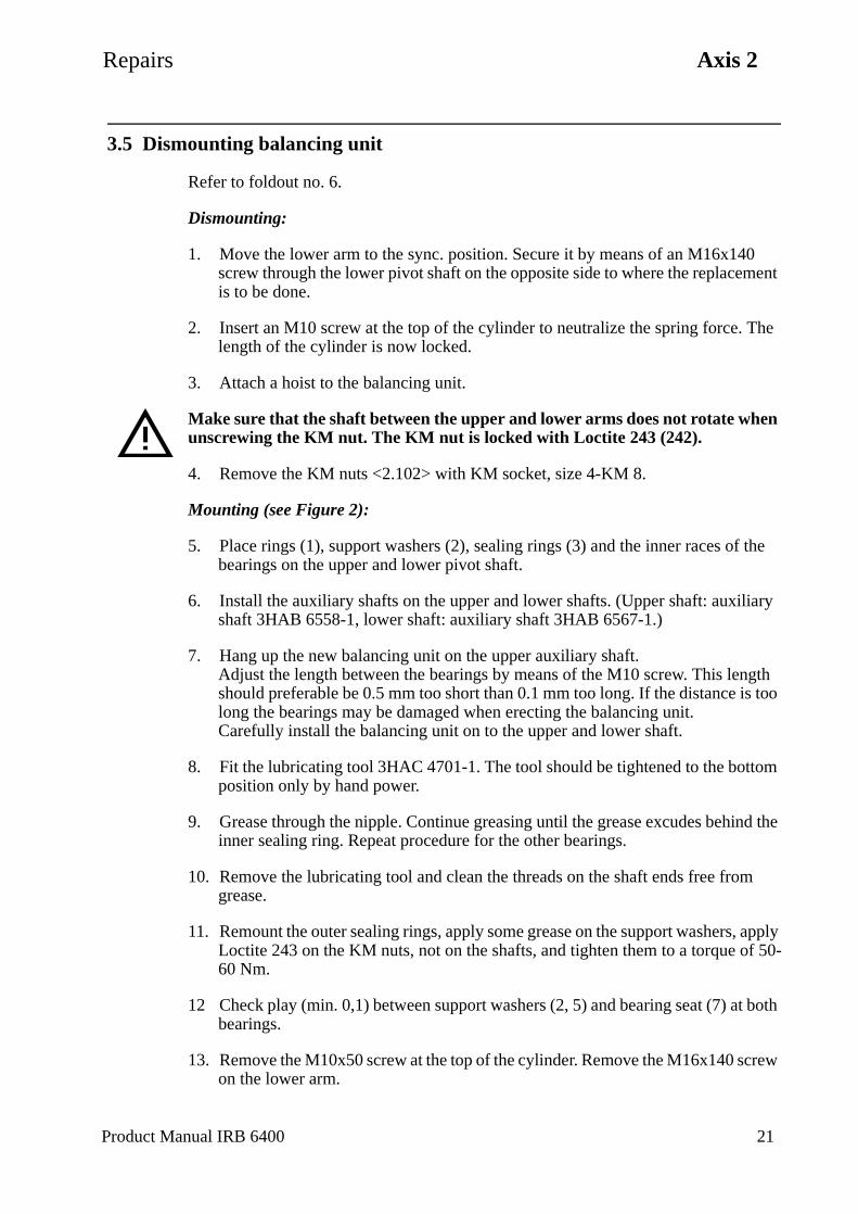
Repairs Axis 2
3.5 Dismounting balancing unit
Refer to foldout no. 6.
Dismounting:
1. Move the lower arm to the sync. position. Secure it by means of an M16x140 screw through the lower pivot shaft on the opposite side to where the replacement is to be done.
2. Insert an M10 screw at the top of the cylinder to neutralize the spring force. The length of the cylinder is now locked.
3. Attach a hoist to the balancing unit.
Make sure that the shaft between the upper and lower arms does not rotate when unscrewing the KM nut. The KM nut is locked with Loctite 243 (242).
4. Remove the KM nuts <2.102> with KM socket, size 4-KM 8.
Mounting (see Figure 2):
5. Place rings (1), support washers (2), sealing rings (3) and the inner races of the bearings on the upper and lower pivot shaft.
6. Install the auxiliary shafts on the upper and lower shafts. (Upper shaft: auxiliary shaft 3HAB 6558-1, lower shaft: auxiliary shaft 3HAB 6567-1.)
7. Hang up the new balancing unit on the upper auxiliary shaft.Adjust the length between the bearings by means of the M10 screw. This length should preferable be 0.5 mm too short than 0.1 mm too long. If the distance is too long the bearings may be damaged when erecting the balancing unit.Carefully install the balancing unit on to the upper and lower shaft.
8. Fit the lubricating tool 3HAC 4701-1. The tool should be tightened to the bottom position only by hand power.
9. Grease through the nipple. Continue greasing until the grease excudes behind the inner sealing ring. Repeat procedure for the other bearings.
10. Remove the lubricating tool and clean the threads on the shaft ends free from grease.
11. Remount the outer sealing rings, apply some grease on the support washers, apply Loctite 243 on the KM nuts, not on the shafts, and tighten them to a torque of 50-60 Nm.
12 Check play (min. 0,1) between support washers (2, 5) and bearing seat (7) at both bearings.
13. Remove the M10x50 screw at the top of the cylinder. Remove the M16x140 screw on the lower arm.
Product Manual IRB 6400 21
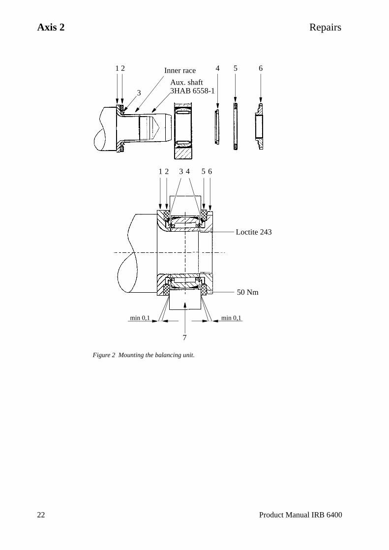
Axis 2 Repairs
Figure 2 Mounting the balancing unit.
1 2 Inner race
3
4 5 6
1 2 3 4 5 6
Loctite 243
50 Nm
min 0,1min 0,1
Aux. shaft3HAB 6558-1
7
22 Product Manual IRB 6400
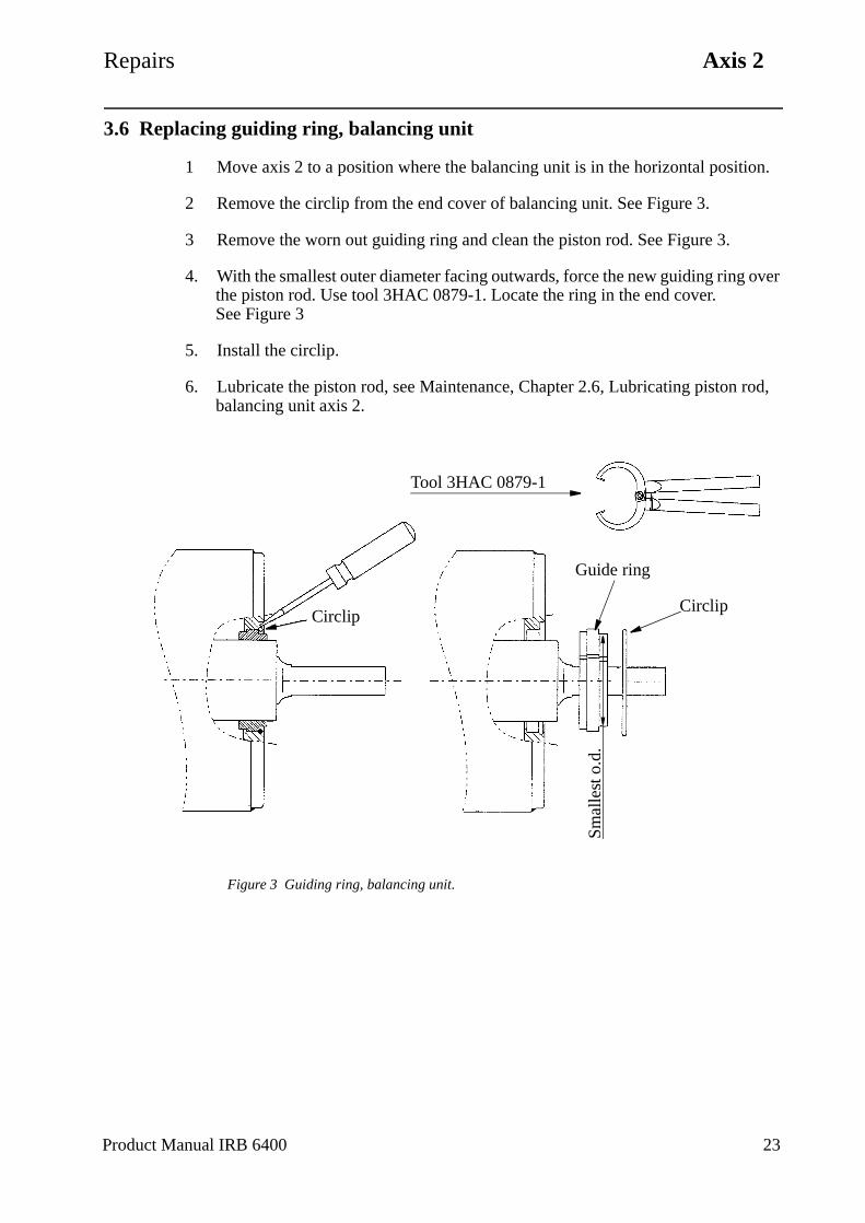
Repairs Axis 2
3.6 Replacing guiding ring, balancing unit
1 Move axis 2 to a position where the balancing unit is in the horizontal position.
2 Remove the circlip from the end cover of balancing unit. See Figure 3.
3 Remove the worn out guiding ring and clean the piston rod. See Figure 3.
4. With the smallest outer diameter facing outwards, force the new guiding ring over the piston rod. Use tool 3HAC 0879-1. Locate the ring in the end cover.See Figure 3
5. Install the circlip.
6. Lubricate the piston rod, see Maintenance, Chapter 2.6, Lubricating piston rod, balancing unit axis 2.
Figure 3 Guiding ring, balancing unit.
Circlip
Guide ring
CirclipSm
alle
st o
.d.
Tool 3HAC 0879-1
Product Manual IRB 6400 23
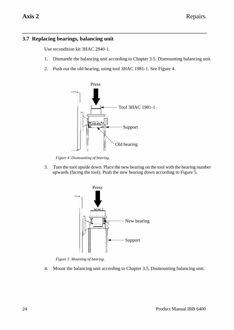
Axis 2 Repairs
24 Product Manual IRB 6400
3.7 Replacing bearings, balancing unit
Use recondition kit 3HAC 2840-1.
1. Dismantle the balancing unit according to Chapter 3.5, Dismounting balancing unit.
2. Push out the old bearing, using tool 3HAC 1981-1. See Figure 4.
Figure 4 Dismounting of bearing.
3. Turn the tool upside down. Place the new bearing on the tool with the bearing number upwards (facing the tool). Push the new bearing down according to Figure 5.
Figure 5 Mounting of bearing.
4. Mount the balancing unit according to Chapter 3.5, Dismounting balancing unit.
Press
Old bearing
Tool 3HAC 1981-1
Support
Press
New bearing
Support
Repairs Axis 2
3.8 Dismounting cables, lower arm/upper arm
Refer to foldout nos. 1:1, 4:1, 4:2, 5, 7:1, 7:2, 8, 10:1, 15:1, 15:2.
Dismounting:
1. Disconnect connectors R2.MP4, R2.MP5-6, R2.CP, R2.CS) inside cover <4:1 (4:2) /2.121> in the frame.
2. Disconnect connector R2.SMB4-6(X5) on the serial measurement board <4:1 (4:2) /2.119>, located in the frame.
3. Remove the small covers in the cover <4:1 (4:2) / 2.112> and feed the cables gen-tly out from the frame. Take the cables through the hole in the plate. Loosen the air hose.
4. Remove the hood <8/38> and unscrew the holder.
Make a written note of the relative positions and order of the cables and air hose, to facilitate refitting in the correct way. See foldout 15:1, 15:2.
5. Remove the cable clamps at the top of the lower arm and on the underside of the upper arm with screws <15:2/2.177>. Leave the clamps on the cabling to keep the right distance between the fixing points when remounting.
6. Disconnect the air connection and customer connectors (R3.CP, R3.CS) on the right side of the upper arm.
7. Disconnect connectors (R3.MP4, R3.FB4) on motor axis 4 as described in chapter 6.1, Replacing motor .
8. Loosen the connector box on the left side of the upper arm, remove the angle bracket <7:1 (7:2)/37> from the box and from the tube shaft.
9. Remove the cover to axis 6. Dismount connectors (R3.MP5, R3.FB5, R3.MP6, R3.FB6) in the box.
10. Pull out the cables through the upper arm, feed at the same time the cables up from the lower arm.
Mounting:
11. Mount in reverse order.
Adjust the length of the cable between the cable clamps <15:2/2.177> at the top of the lower arm and the clamps <15:2/2.177> on the upper arm, at the longest dis-tance when the upper arm is moved down. The cable that comes out from the tube shaft forms a loop down against the parallel bar. The loop should be big enough so that it runs quite close to the inside of the cover.
Product Manual IRB 6400 25

Axis 2 Repairs
26 Product Manual IRB 6400

Repairs Axis 3
4 Axis 3
4.1 Replacing motor
Refer to foldout 4:1, 4:2.
Dismounting:
Be careful not to tap or hit the shaft axially, nor displace the shaft axially in any way, as this could give rise to an incorrect air gap in the brake.
1. Lower the balancing weight to its lowest position and secure axis 3 with a hoist, or mount two extra mechanical stops on each side of the moving stop on axis 3, to lock the movement of axis 3.
Danger! Be careful! Make sure that the balancing weight or the upper arm are locked in their positions and that they cannot move when the motor with brake is dismounted.
2. Unscrew the 3 screws on the top of motor 3. Remove the e cover.
3. Unscrew the 4 cable inlet cover screws.
4. Disconnect connectors R3.MP3 and R3.FB3.
5. Attach a hoist to the motor. The weight of the motor is 17 kg.
6. Unscrew the screws <1.31> for the motor.
7. Pull out the motor.
8. Loosen screw <1.30> and mount a screw with a length of 150 mm and pull off the gear with a puller.
Mounting:
9. Mount a fully threaded pin in the motor shaft and press the gear on to the shaft with a nut and washer. Mount screw <1.30> through the gear, torque 45 Nm, Loctite 242.
This is to avoid axial force through the bearings in the motor.
10. Ensure that the assembly surfaces are clean and unscratched.
11. Mount O-ring <1.28>, applying some grease.
12. Mount motor, lubricate screws <1.31> with Molycote 1000 and tighten with torque 50 Nm.
Do not forget to remove the two extra mechanical stops, if they are used.
Product Manual IRB 6400 27
Axis 3 Repairs
13. Calibrate the robot as described in Chapter 9, Calibration.
Tightening torque:
Screws for motor, item 1.31: 50 Nm
Screw for gear, item 1.30: 45 Nm
4.2 Replacing gearbox
Refer to foldout nos. 4:1, 4:2.
Dismounting:
1. Dismount motor as described in Chapter 4.1, Replacing motor.
2. Unscrew screws <1.38.2> and dismount the motor socket <1.38.1>.
3. Mount 2 guide pins, M12 through the gearbox.
4. Loosen screws <1.5> and <1.7>.
5. Pull out the gear box <1.3>, hanging on the guide pins.
Mounting:
6. Clean the surfaces in the frame, lower arm and gearbox.
7. Mount 2 guide pins, M12.
8. Mount friction rings <1.16, 1.37> and O-ring <1.4>.
9. Put the gear box on the 2 guide pins and place the friction ring <1.16> on to the gearbox.
10. Mount screws <1.5> and <1.7>, lubricate with Molycote 1000 and tighten screw <1.7> with 300 Nm and screw <1.5> with 120 Nm.
11. Mount O-ring <1.14>.
12. Put the motor socket on the 2 guide pins.
Note! The position of the magnetic plugs.
13. Mount screws <1.38.2>, lubricate with Molycote 1000 and tighten with a torque of 120 Nm.
14. Mount the motor as described in Chapter 4.1, Replacing motor.
28 Product Manual IRB 6400
Repairs Axis 3
Tightening torque:
Screw joint gearbox/parallel arm, item 1. 7: 300 NmScrew joint gearbox/parallel arm, item 1.5: 120 NmScrew joint motor socket/frame, item 1.38.2: 120 Nm
4.3 Dismounting parallel arm
Refer to foldout no. 5.
Dismounting:
1. Remove the lower arm as in Chapter 3.3, Replacing lower arm.
2. Place the arm on a workbench.
3. Attach a hoist to the parallel arm.
4. Force the parallel arm to the right, seen from the rear.
5. Lift the parallel arm away.
Mounting:
6. Place the parallel arm in position.
7. Press the parallel arm into the lower arm.
8. Mount the lower arm as described in Chapter 3.3, Replacing lower arm.
4.4 Replacing parallel bar with bearings
Refer to foldout no. 5, 8.
Dismounting:
IMPORTANT! Secure axis 3 with two extra mechanical stops, so that the balancing weight for axis 3 cannot fall down, and secure the upper arm with a hoist or similar.
1. Attach a hoist to the parallel bar.
NOTE! Mark the clamps so that they can be refitted in the same place.
2. Dismount clamps <5/1.2.2> by the parallel arm.
3. Dismount clamps <8/31.3.2> by the upper arm. Lift the bar away.
Product Manual IRB 6400 29
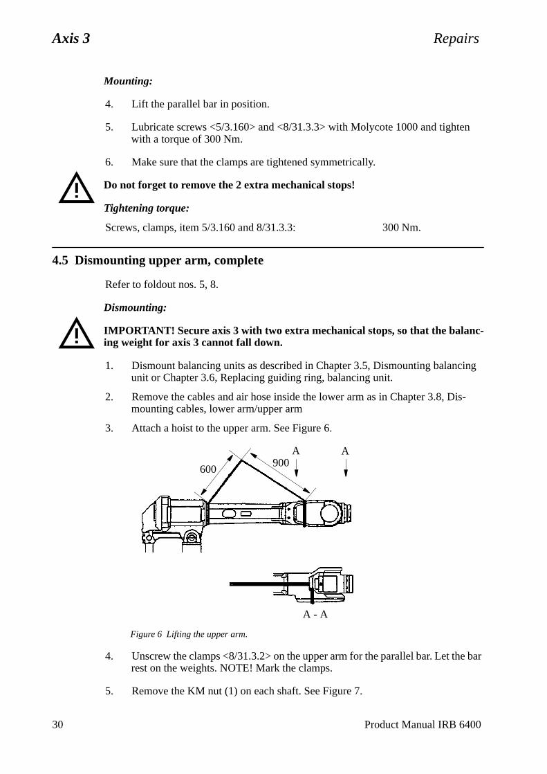
Axis 3 Repairs
Mounting:
4. Lift the parallel bar in position.
5. Lubricate screws <5/3.160> and <8/31.3.3> with Molycote 1000 and tighten with a torque of 300 Nm.
6. Make sure that the clamps are tightened symmetrically.
Do not forget to remove the 2 extra mechanical stops!
Tightening torque:
Screws, clamps, item 5/3.160 and 8/31.3.3: 300 Nm.
4.5 Dismounting upper arm, complete
Refer to foldout nos. 5, 8.
Dismounting:
IMPORTANT! Secure axis 3 with two extra mechanical stops, so that the balanc-ing weight for axis 3 cannot fall down.
1. Dismount balancing units as described in Chapter 3.5, Dismounting balancing unit or Chapter 3.6, Replacing guiding ring, balancing unit.
2. Remove the cables and air hose inside the lower arm as in Chapter 3.8, Dis-mounting cables, lower arm/upper arm
3. Attach a hoist to the upper arm. See Figure 6.
Figure 6 Lifting the upper arm.
4. Unscrew the clamps <8/31.3.2> on the upper arm for the parallel bar. Let the bar rest on the weights. NOTE! Mark the clamps.
5. Remove the KM nut (1) on each shaft. See Figure 7.
AA
A - A
600900
30 Product Manual IRB 6400
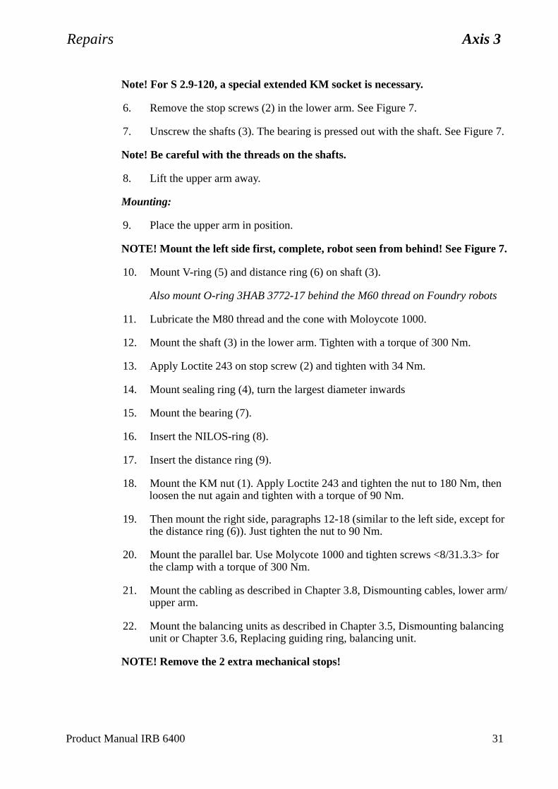
Repairs Axis 3
Note! For S 2.9-120, a special extended KM socket is necessary.
6. Remove the stop screws (2) in the lower arm. See Figure 7.
7. Unscrew the shafts (3). The bearing is pressed out with the shaft. See Figure 7.
Note! Be careful with the threads on the shafts.
8. Lift the upper arm away.
Mounting:
9. Place the upper arm in position.
NOTE! Mount the left side first, complete, robot seen from behind! See Figure 7.
10. Mount V-ring (5) and distance ring (6) on shaft (3).
Also mount O-ring 3HAB 3772-17 behind the M60 thread on Foundry robots
11. Lubricate the M80 thread and the cone with Moloycote 1000.
12. Mount the shaft (3) in the lower arm. Tighten with a torque of 300 Nm.
13. Apply Loctite 243 on stop screw (2) and tighten with 34 Nm.
14. Mount sealing ring (4), turn the largest diameter inwards
15. Mount the bearing (7).
16. Insert the NILOS-ring (8).
17. Insert the distance ring (9).
18. Mount the KM nut (1). Apply Loctite 243 and tighten the nut to 180 Nm, then loosen the nut again and tighten with a torque of 90 Nm.
19. Then mount the right side, paragraphs 12-18 (similar to the left side, except for the distance ring (6)). Just tighten the nut to 90 Nm.
20. Mount the parallel bar. Use Molycote 1000 and tighten screws <8/31.3.3> for the clamp with a torque of 300 Nm.
21. Mount the cabling as described in Chapter 3.8, Dismounting cables, lower arm/upper arm.
22. Mount the balancing units as described in Chapter 3.5, Dismounting balancing unit or Chapter 3.6, Replacing guiding ring, balancing unit.
NOTE! Remove the 2 extra mechanical stops!
Product Manual IRB 6400 31
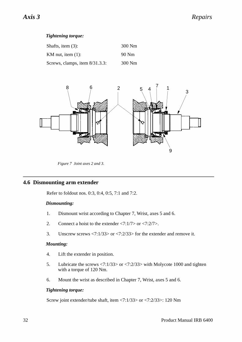
Axis 3 Repairs
Tightening torque:
Shafts, item (3): 300 Nm
KM nut, item (1): 90 Nm
Screws, clamps, item 8/31.3.3: 300 Nm
Figure 7 Joint axes 2 and 3.
4.6 Dismounting arm extender
Refer to foldout nos. 0:3, 0:4, 0:5, 7:1 and 7:2.
Dismounting:
1. Dismount wrist according to Chapter 7, Wrist, axes 5 and 6.
2. Connect a hoist to the extender <7:1/7> or <7:2/7>.
3. Unscrew screws <7:1/33> or <7:2/33> for the extender and remove it.
Mounting:
4. Lift the extender in position.
5. Lubricate the screws <7:1/33> or <7:2/33> with Molycote 1000 and tighten with a torque of 120 Nm.
6. Mount the wrist as described in Chapter 7, Wrist, axes 5 and 6.
Tightening torque:
Screw joint extender/tube shaft, item <7:1/33> or <7:2/33>: 120 Nm
2 5 476
9
13
8
32 Product Manual IRB 6400
Repairs Pushbutton unit for release of brakes
5 Pushbutton unit for release of brakes
5.1 Replacing pushbutton unit
Refer to foldout no. 4:1(4:2 for S 2.9-120)
Dismounting:
1. Remove the pushbutton unit <2.3> located in the frame.
2. Disconnect connectors R3.BU1-6(X8), R3.BU1-3(X9), R3.BU4-6(X10).
Mounting:
3. In reverse order.
Product Manual IRB 6400 33

Pushbutton unit for release of brakes Repairs
34 Product Manual IRB 6400
Repairs Axis 4
6 Axis 4
6.1 Replacing motor
Refer to foldout no. 8
Dismounting:
1. Drain the gearbox by removing oil plugs <31.26>.
2. Unscrew the 4 cable inlet cover screws.
3. Unscrew the 3 screws on the top of motor 4. Remove the cover.
4. Disconnect connectors R3.MP4 and R3.FB4.
5. Secure axis 4 so it cannot rotate when the motor is removed.
6. Remove cover <31.28>.
7. Remove the screws <31.14> and nuts <31.18>.
8. Unscrew screws <31.25> and pull out the motor.
Be careful not to tap or hit the shaft axially, nor displace the shaft axially in any way, as this could give rise to an incorrect air gap in the brake.
9. To press the gear off the motor shaft, oil must be injected into the centre of the gear. Mount SKF Oil injector 226270 + SKF nipple 725 870 + 234 063 in the centre and press the gear off the shaft.
Caution: Make sure that the oil injector is filled with oil.
Mounting:
10. Press the gear on to the motor shaft. Use tools 3HAA 7601-070 and 3HAB 5674-1.
Remove the B-side cover at the rear of the motor and place support 3HAA 7601-070 under the motor shaft, to avoid axial loading of the bearings in the motor.
11. Mount O-ring <31.2> and insert motor, tighten screws <31.25>, torque 22 Nm.
12. Adjust the intermediate wheel as described in Chapter 6.2, Replacing and adjust-ing intermediate gear.
13. Mount a new cork seal <31.29> on the cover.
14. Fill the gearbox with oil, type ABB 1171 2016 -604, volume 6 litres. Regarding replacement oils see the Maintenance Manual IRB 6400.
15. Reconnect connectors R3.MP4 and R3.FB4. Mount the cover.
16. Calibrate the robot as described in Chapter 9, Calibration.
Product Manual IRB 6400 35
Axis 4 Repairs
1.18>
Tightening torque:
Screws for motor, item 31.25: 22 Nm
6.2 Replacing and adjusting intermediate gear
Refer to foldout no. 8.
Dismounting:
1. Drain the gearbox of oil.
2. Secure axis 4 mechanically.
3. Remove the cover <31.28>.
4. Remove the motor as described in Chapter 6.1, Replacing motor.
5. Unscrew the screws <31.14>.
6. Unscrew nuts <31.18> and remove the wedges <31.17> and remove screws <31.14>.
7. Pull out the intermediate gear unit.
Mounting:
8. Mount the gear and tighten screws <31.14> only very slightly.
9. Refit the motor.
10. Adjust the play by moving the intermediate wheel to obtain the minimum play between the final gear and the motor gear, at four points, by turning axis 4. Ensure that when axis 4 is turned, the gears do not “scrape” together.
11. Tighten screws <31.14> with a torque of 69 Nm.
12. Insert the 3 wedges <31.17> with 3 tension washers <31.43> and the nut <3on <31.16>, tighten with a torque of 8 Nm.
Note! Fit the tension washers with their concave sides facing each other.
NOTE! Check the play.
13. Mount cover <31.28> with a new seal <31.29>.
14. Fill the gearbox with oil, ABB 1171 2016-604, volume 6 litres. Regarding replacements oils, see the Maintenance Manual IRB 6400.
15. Calibrate the robot as described in Chapter 9, Calibration.
36 Product Manual IRB 6400
Repairs Axis 4
Tightening torque:
Screw joint intermediate wheel, item 31.14: 69 Nm
Nuts/wedge joints, item 31.18: 8 Nm
Fixing screws for motor, item 31.25: 22 Nm
6.3 Replacing final gear
Refer to foldout no. 8.
Dismounting:
1. Dismount cabling in the upper arm as in Chapter 3.8, Dismounting cables, lower arm/upper arm
2. Dismount adjustable intermediate gear as in Chapter 6.2, Replacing and adjust-ing intermediate gear.
3. Mount the special hydraulic tool, ABB 6896 134-AN, to the tubular shaft end.
4. Remove the cover in the gear <31.11> and mount nipple, SKF 234 063, with NIKE quick coupling, I-AQU 8.
5. Mount tool, ABB 6396 134-AT with hydraulic cylinder NIKE I-CH 612, on the gear <31.11> with three hexagon screws M12x70 10.9.
6. Connect pump 6369 901-286 to the cylinder and nipple in the gear.
7. Pump up the pressure, with both taps on the valve open. When the gear moves sufficiently so that the pressure disappears between the gear and the shaft, close one of the taps. Continue pumping in this way until the gear has been removed.
Be careful with the surface at the end of the shaft. Otherwise there may be oil leakage.
Mounting:
8. Heat up the gear <31.11> to 160 oC using an induction heater or oven.
9. Mount tool ABB 6896 134-BU on the end of the tube shaft.
The following steps must be carried out in sequence while the gear is still hot.
10. Mount gear on the tube shaft.
11. Mount tool, ABB 6896 134-FK.
12. Mount hydraulic cylinder NIKE I-CH 612 with regulator.
13. Press the gear on the shaft with a force of 16 000 N, equivalent to 8.7-9.2 MPA, check the pressure gauge (part of pump 6369 901-286).
Product Manual IRB 6400 37
Axis 4 Repairs
14. Check that the distance ring <31.12> is pressed in position behind the gear.
15. The pressure must be retained until the gear has cooled down and shrunk on to the shaft.
16. Mount intermediate wheel as in Chapter 6.2, Replacing and adjusting intermedi-ate gear.
17. Mount the cabling in the upper arm as in Chapter 3.8, Dismounting cables, lower arm/upper arm.
18. Calibrate the robot as described in Chapter 9, Calibration.
6.4 Dismounting tube shaft, upper arm
Refer to foldout no. 8.
Dismounting:
1. Dismount wrist as in Chapter 7.1, Dismounting the wrist.
2. Dismount cabling in upper arm as in Chapter 3.8, Dismounting cables, lower arm/upper arm
3. Dismount the motor axis 4 as in Chapter 6.1, Replacing motor.
4. Dismount the adjustable intermediate gear as in Chapter 6.2, Replacing and adjusting intermediate gear.
5. Dismount final gear as in Chapter 6.3, Replacing final gear.
6. Remove the mechanical stop <31.23> for axis 4.
7. Rotate axis 4 so that the damper <31.22> is visible and can be removed.
8. Remove the stop on shaft <31.20>.
9. Press the tube shaft out with tool 3HAB 8079-1.
N.B. The extender 3HAB 8008-1, included in 3HAB 8079-1, can also be used to get the tube through the second bearing.
10. Knock the bearing <31.6> out.
Mounting:
11. Cover the sliding surfaces, for the seal rings, with some tape.
12. Apply some grease on the diameters of the tubular shaft where the seals must pass.
13. “Fix” the NILOS-ring <31.7> in the upper arm housing with some grease.
38 Product Manual IRB 6400
Repairs Axis 4
ear-
-BU
tor
oc-
d e
r arm
arm.
ide
14. Mount the seal <31.8> on tube shaft.
15. Mount bearing <31.6>. Use tool 6896 134-S + 6896 134-S + NIKE 1-CH-612. Alternatively, heat up the bearing to 120°C and mount on the shaft. Let the bing cool down before further assembly.
16. Grease the bearing.
17. Press the shaft into the housing using the tool 6896 134-FL with holder on+ NIKE 1-CH-612.
18. Mount the distance ring <31.12> on the tube.
19. Mount the final gear according to Chapter 6.3, Replacing final gear.
20. Mount the motor and intermediate wheel as in Chapter 6.1, Replacing moand Chapter 6.2, Replacing and adjusting intermediate gear.
21. Mount the stop <31.20> on the tube shaft. Lock the screws <31.21> with Ltite 242 and tighten with a torque of 84 Nm.
22. Mount the damper <31.22> and the mechanical stop <31.23> with seal antighten screws <31.25> with a torque of 22 Nm. Use Loctite 242. Apply somgrease on the sliding surfaces.
23. Mount the cabling as in Chapter 3.8, Dismounting cables, lower arm/uppe
24. Calibrate the robot as described in Chapter 9, Calibration.
Tightening torque:
Screws for stop, item 31.21: 84 Nm
Screws mechanical stop, item 31.25: 22 Nm
6.5 Replacing seals and bearings, upper arm
Refer to foldout no. 8.
Dismounting:
1. Dismount the tube shaft as in Chapter 6.4, Dismounting tube shaft, upper
2. Knock bearing <31.6> off the tube shaft <5>.
3. Knock bearing <31.6> out, inside housing <31.3>.
4. Knock out the sealing <31.10>.
Mounting:
5. Mount a new sealing ring <31.10>, apply some grease on the diameter ins
Product Manual IRB 6400 39

Axis 4 Repairs
the upper arm house. Use tool 6896 134-FA.
6. Mount seal ring <31.8> on to the tube shaft.
7. Mount bearing <31.6> according to Chapter 6.4, Dismounting tube shaft, upper arm, point 15.
NOTE! Let the bearing cool down before mounting the shaft.
8. Apply grease in the bearing.
9. Mount the tube shaft as described in Chapter 6.4, Dismounting tube shaft, upper arm.
40 Product Manual IRB 6400
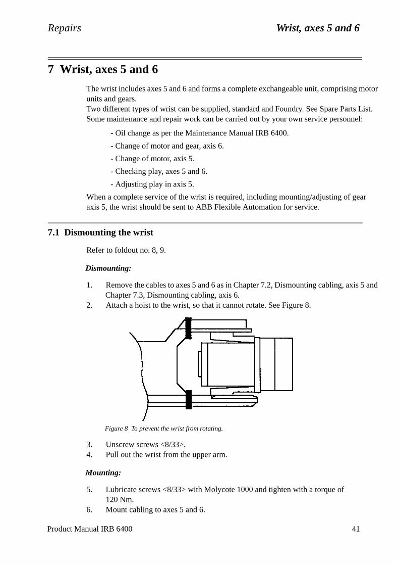
Repairs Wrist, axes 5 and 6
7 Wrist, axes 5 and 6
The wrist includes axes 5 and 6 and forms a complete exchangeable unit, comprising motor units and gears.Two different types of wrist can be supplied, standard and Foundry. See Spare Parts List.Some maintenance and repair work can be carried out by your own service personnel:
- Oil change as per the Maintenance Manual IRB 6400.
- Change of motor and gear, axis 6.
- Change of motor, axis 5.
- Checking play, axes 5 and 6.
- Adjusting play in axis 5.
When a complete service of the wrist is required, including mounting/adjusting of gear axis 5, the wrist should be sent to ABB Flexible Automation for service.
7.1 Dismounting the wrist
Refer to foldout no. 8, 9.
Dismounting:
1. Remove the cables to axes 5 and 6 as in Chapter 7.2, Dismounting cabling, axis 5 and Chapter 7.3, Dismounting cabling, axis 6.
2. Attach a hoist to the wrist, so that it cannot rotate. See Figure 8.
Figure 8 To prevent the wrist from rotating.
3. Unscrew screws <8/33>.4. Pull out the wrist from the upper arm.
Mounting:
5. Lubricate screws <8/33> with Molycote 1000 and tighten with a torque of 120 Nm.
6. Mount cabling to axes 5 and 6.
Product Manual IRB 6400 41
Wrist, axes 5 and 6 Repairs
the
r 6. .
it.
7. Pressure test Foundry robots according to Chapter 7.3, Dismounting cabling, axis 6.
8. Calibrate the robot as described in Chapter 9, Calibration.
Tightening torque:
Screw joint wrist/tube shaft, item 33: 120 Nm
7.2 Dismounting cabling, axis 5
Refer to foldout no. 7:1, 7:2
Dismounting:
1. Remove the cover for the cables to axis 6 on the upper arm tube.2. Loosen the connector box on the left side, with screws <43>, unscrew angle
bracket <37> from the box and the upper arm tube.3. Dismount connectors R3.MP6, R3.FB6 on the box with screws <41>.4. Turn the box around and dismount connectors R3.MP5, R3.FB5 with screws
<41>.5. Dismount the wrist as described in Chapter 7.1, Dismounting the wrist.6. Unscrew the 4 cable inlet cover screws.7. Unscrew the 3 screws on the top of motor 5. Remove the B-side cover.8. Loosen connectors R4.MP5, R3.FB5 on the motor.
Mounting:
9. In reverse order.
7.3 Dismounting cabling, axis 6
Refer to foldout no. 7:1, 7:2.
Dismounting:
1. Run axis 5 to +90° position.2. Remove the covers for cables to axis 6 on the upper arm tube and wrist.3. Dismount connectors R3.MP6, R3.FB6 on the box with screw <41>. Loosen
cable bracket and the sealing with screws <32>.4. Dismount the cover over the cable pit on the motor.5. Dismount connectors R4.MP6, R4.FB6 under the cover at the rear of moto
Loosen the cover by using the thread in the centre hole and a suitable toolAlternative:Press the cover out from the inside with a screw driver through the cable pNote! Be careful not to damage the cables or resolver.
6. Loosen the carrier mounted on the motor with screws <41>.
42 Product Manual IRB 6400
Repairs Wrist, axes 5 and 6
alve
econds
t thessure
ne by
e
rack
ar. Use
Mounting:
7. Mount in reverse order. (Keep axis 5 in 90° position.)
Note!Foundry robots must be leaktested after cable replacement.
Test procedure for IRB6400 Foundry axis 6:
1. Remove the plug on the back of the 6th axis motor.2. Install test device, 3HAC 0207-1 and 3HAC 4618-1, which consists of a gauge, v
and adapter connected to compressed air.3. The chamber is pressurized to 0.2 bar and the valve is then closed.
Note!Be careful so the camber is not overpressured.
4. The gauge is monitored to ensure only 0.1 bar pressure loss occurs over a 45 speriod.This pressure loss is because air will leak through the cables. It´s important thacables in the upper arm box are connected and the box is closed i.e. the air pre
will be lost in the square shaped Burndy connectors in the 1st axis cavity.5. If pressure is not maintained, the source of the leak must be located. This is do
spraying a leak detecting around suspect areas until the leak has been located.
If leak is found, take following action(s):
• In the back cover of the motor - apply latex under the back cover´s flange.
• Around any screw - apply latex under the screw head.
• Leakage through cable exit joints in cup of 6th axis cable assembly - exchange thcable.
7.4 Replacing motor axis 5
Refer to foldout no. 10.
Dismounting:
1. Dismount the wrist as described in Chapter 7.1, Dismounting the wrist.2. Drain the oil by opening both magnetic plugs.3. Dismount screw <33>. Press out the motor <1> with pin screws (M8x65). Keep t
of the shims <7> between the motor flange and wrist housing.4. Measure the distance between the motor flange and the outer surface of the ge
tool 6896 134-GN. Make a written note of the distance.
Product Manual IRB 6400 43
Wrist, axes 5 and 6 Repairs
Be careful not to tap or hit the shaft axially, nor displace the shaft axially in any way, as this could give rise to an incorrect air gap in the brake.
5. Press out the gear from the shaft. Use nipple 6896 134-AA + TREDO washer as a seal + SKF-nipple 101 8219 + SKF oil injector 226270.
Caution: Make sure the oil injector is filled with oil.
N.B.This gear is matched with the other parts of the bevel gear <6/3> for axis 5. If the motor is changed, the gear must be moved over to the new motor axis. If the gear is damaged, the complete bevel gear unit must be replaced. Please contact ABB Flexible Automation when replacement of the bevel gear unit is necessary. 6. Press the gear on to the new motor. Use tools 3HAA 7601-070 + 3HAB 5674-1.
Note!Remove the cover at the rear of the motor and place support 3HAA 7601-070 under the motor shaft, to avoid axial loading of the bearings in the motor.
7. Check the distance to the gear with tool 6896 134-GN. If the distance differs from the earlier measurement, an adjustment must be made by adding or remov-ing shims <7>.
8. Release the brake. Mount the motor. Use a new O-ring <24>. Apply Loctite 243 on screws <33> and tighten with a torque of 24 Nm.
9. Fill the gearbox with oil according to the Maintenance Manual IRB 6400.
Tightening torque:
Screw joint motor/wrist housing, item 33: 24 Nm
7.5 Replacing motor/gear axis 6.
Refer to foldout nos. 10 and 12.It is not necessary to remove the wrist from the upper arm.
Dismounting:
1. Dismount cabling for axis 6 acc. to Chapter 7.3, Dismounting cabling, axis 6.2. Drain the grease. Open both magnetic plugs.
Note! It is not necessary to drain the wrist, if the position of the wrist permits.3. Unscrew screws <10>. Dismount shaft <10> with help of pinscrews M8x65).4. Dismount cover <10:108>. Dismount cover <10> by deformation (a new cover
must be mounted). Loosen screws <10/107>.5. Free the drive unit from the shaft <10/106> and lift out.6. Loosen screws <11/4>. Dismount the gear with the help of 2 screws (M8 holes
in the motor flange).7. Loosen screws <12/5>. Dismount the pinion with tool 3HAA 7601-043.
44 Product Manual IRB 6400
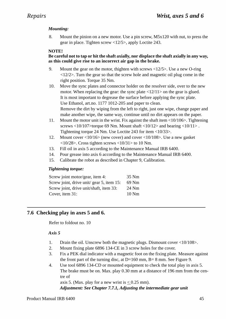
Repairs Wrist, axes 5 and 6
Product Manual IRB 6400 45
Mounting:
8. Mount the pinion on a new motor. Use a pin screw, M5x120 with nut, to press the gear in place. Tighten screw <12/5>, apply Loctite 243.
NOTE!Be careful not to tap or hit the shaft axially, nor displace the shaft axially in any way, as this could give rise to an incorrect air gap in the brake.
9. Mount the gear on the motor, thighten with screws <12/5>. Use a new O-ring <12/2>. Turn the gear so that the screw hole and magnetic oil plug come in the right position. Torque 35 Nm.
10. Move the sync plates and connector holder on the resolver side, over to the new motor. When replacing the gear: the sync plate <12/11> on the gear is glued. It is most important to degrease the surface before applying the sync plate.Use Ethanol, art.no. 1177 1012-205 and paper to clean.Remove the dirt by wiping from the left to right, just one wipe, change paper and make another wipe, the same way, continue until no dirt appears on the paper.
11. Mount the motor unit in the wrist. Fix against the shaft item <10/106>. Tightening screws <10/107>torque 69 Nm. Mount shaft <10/12> and bearing <10/11> . Tightening torque 24 Nm. Use Loctite 243 for item <10/33>.
12. Mount cover <10/16> (new cover) and cover <10/108>. Use a new gasket <10/28>. Cross tighten screws <10/31> to 10 Nm.
13. Fill oil in axis 5 according to the Maintenance Manual IRB 6400.14. Pour grease into axis 6 according to the Maintenance Manual IRB 6400.15. Calibrate the robot as described in Chapter 9, Calibration.
Tightening torque:
Screw joint motor/gear, item 4: 35 NmScrew joint, drive unit/ gear 5, item 15: 69 NmScrew joint, drive unit/shaft, item 33: 24 NmCover, item 31: 10 Nm
7.6 Checking play in axes 5 and 6.
Refer to foldout no. 10
Axis 5
1. Drain the oil. Unscrew both the magnetic plugs. Dismount cover <10/108>.2. Mount fixing plate 6896 134-CE in 3 screw holes for the cover.3. Fix a PEK dial indicator with a magnetic foot on the fixing plate. Measure against
the front part of the turning disc, at D=160 mm, B= 8 mm. See Figure 9.4. Use tool 6896 134-CD or mounted equipment to check the total play in axis 5.
The brake must be on. Max. play 0.30 mm at a distance of 196 mm from the cen-tre of axis 5. (Max. play for a new wrist is < 0.25 mm).Adjustment: See Chapter 7.7.1, Adjusting the intermediate gear unit
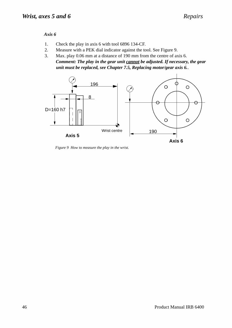
Wrist, axes 5 and 6 Repairs
Axis 6
1. Check the play in axis 6 with tool 6896 134-CF.2. Measure with a PEK dial indicator against the tool. See Figure 9.3. Max. play 0.06 mm at a distance of 190 mm from the centre of axis 6.
Comment: The play in the gear unit cannot be adjusted. If necessary, the gear unit must be replaced, see Chapter 7.5, Replacing motor/gear axis 6..
Figure 9 How to measure the play in the wrist.
190
D=160 h7
8
Axis 5Axis 6
196
Wrist centre
46 Product Manual IRB 6400
Repairs Wrist, axes 5 and 6
7.7 Adjusting play in axis 5.
Refer to foldout no.10
1. Remove the cover <10/108>. Investigate the cause of the excessive play on axis 5. Then take action as described in one of the following alternatives:
A. The intermediate gear unit <10/105> is stuck, the play between gears<10/104> and <10/106> is excessive. The play must be 0 - 0.08 mm, meas-ured at three different points.
Action: Adjust the play as described in Chapter 7.7.1, Adjusting the intermediate gear unit
B. The intermediate gear unit <10/105> has become loose. Check that the gears <10/104> and other parts (<10/18>, <10/20>, <10/21>, <10/22> and <10/43>) are not damaged or loose.
Action: Replace damaged parts and adjust the play as described in Chapter 7.7.1, Adjusting the intermediate gear unit
C. There is play in the bearings of the intermediate gear unit <10/105>.
Action: Adjust the bearing as described in Chapter 7.7.2, Adjusting the interme-diate gear unit bearings and adjust to the correct play as described in Chapter 7.7.1, Adjusting the intermediate gear unit.
Product Manual IRB 6400 47
Wrist, axes 5 and 6 Repairs
n
ly
in
7.7.1 Adjusting the intermediate gear unit
Refer to foldout no. 10
1. Remove the wedges <10/21>. Check that they are not damaged.
2. Adjust the intermediate gear unit <10/105> with the centre screw <10/18>. The gear mesh play between the pinion <10:1/2> and the gearwheel must be 0 - 0.08 mm. Measure the play at three different places. Use the tool 6896 134-CE and a dial indicator on a magnetic foot.
3. Tighten the intermediate gear unit <10/105> using the screw <10/18>, to a torque of 93 Nm ± 5%.
4. Mount the wedges <10/21> and the 4 tension washers <10/43> (fit them as showon foldout 10).
5. Tighten the wedges alternately with the nuts <10/22>. Torque 12 Nm ± 5%. AppLoctite 243 to lock the nuts.Check the gear play after tightening as described in Chapter 7.6, Checking play axes 5 and 6.
Tightening torque:
Screw for intermediate wheel, item 10:1/18: 93 Nm ± 5%Nuts for wedges, item 10:2/22: 12 Nm ± 5%
7.7.2 Adjusting the intermediate gear unit bearings
Refer to Figure 10.The roller bearings (1) must be pretensioned to eliminate any backlash.
1. Remove the stop screw (2) and the locknut (3).
2. Clean the threads in the hub (4) and the locknut (3).
3. Apply Loctite 290 on the threads in the hub and the locknut.
4. Tighten the locknut (3). Torque 85 Nm ± 5% (for a replacement bearing).Use the tool 3HAB 1022-1 together with the torque-wrench.
Note!If the same bearing is fitted again, the torque should be 70-75 Nm.
5. Fit the stop screw (2), extra locking. Apply Loctite 243.
48 Product Manual IRB 6400
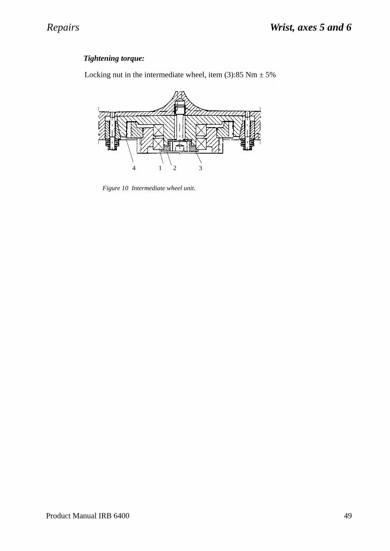
Repairs Wrist, axes 5 and 6
Tightening torque:
Locking nut in the intermediate wheel, item (3):85 Nm ± 5%
Figure 10 Intermediate wheel unit.
4 1 2 3
Product Manual IRB 6400 49

Wrist, axes 5 and 6 Repairs
50 Product Manual IRB 6400

Repairs Motor units
r unit. t of
and
8 Motor units
8.1 General
Each manipulator axis is provided with a motor unit consisting of:
- A synchronous AC motor
- A brake unit
- A feedback unit.
A gear on the output shaft of the motor forms together with the gear on each axis, the complete gear unit. Dismounting/mounting of the gear unit is described in an earlier chapter of this manual.The electro-magnetic brake is built into the motor unit. The brake is released by a 24 V DC supply. For brake release see Section 7, Installation and Commissioning.The feedback unit consists of a resolver mounted on the motor shaft and is built into the motor unit in a similar way as the brake.Power and signal connections to the motor units are via separate cables between connections points inside the manipulator and each motor. The cables are connected to the motor units with connectors.
- The feedback unit is fitted by the motor manufacturer and must never be sep-arated from the motor.
- The communication angle is + 90° (COMOFF=2048). The motors never need commutating.
- The motor, resolver and brake is to be regarded as an replacement motoFaulty motor units are repaired by the motor manufacturer at the requesthe ABB Flexible Automation service organisation.
- The cable routing is shown in Figure 11. Note that the signal connectionthe power connection must not be entwined.
Figure 11 Cable routing in the motor unit.
Power connectionSignal connection
Product Manual IRB 6400 51
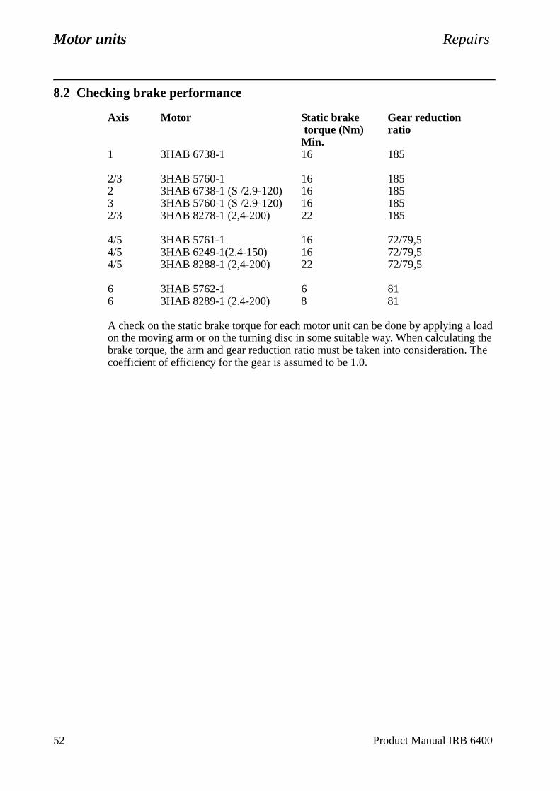
Motor units Repairs
8.2 Checking brake performance
Axis Motor Static brake Gear reduction torque (Nm) ratioMin.
1 3HAB 6738-1 16 185
2/3 3HAB 5760-1 16 1852 3HAB 6738-1 (S /2.9-120) 16 1853 3HAB 5760-1 (S /2.9-120) 16 1852/3 3HAB 8278-1 (2,4-200) 22 185
4/5 3HAB 5761-1 16 72/79,54/5 3HAB 6249-1(2.4-150) 16 72/79,54/5 3HAB 8288-1 (2,4-200) 22 72/79,5
6 3HAB 5762-1 6 816 3HAB 8289-1 (2.4-200) 8 81
A check on the static brake torque for each motor unit can be done by applying a load on the moving arm or on the turning disc in some suitable way. When calculating the brake torque, the arm and gear reduction ratio must be taken into consideration. The coefficient of efficiency for the gear is assumed to be 1.0.
52 Product Manual IRB 6400
Repairs Calibration
9 Calibration
9.1 General
The robot measurement system consists of one feedback unit for each axis and a meas-urement board that continuously keeps track of the current robot position.The measurement board memory has a battery backup.
Note! The accumulator unit will be fully recharged when the mains supply has been on for 36 hrs. without any power interruptions.
The measurement system must be carefully calibrated (as described in Chapter 9.2, Calibration procedure) if any of the resolver values are changed. This happens when:
- parts affecting the calibration position have been replaced on the robot.
The system needs to be roughly calibrated (as described in Chapter 9.3, Setting the cal-ibration marks on the manipulator) if the contents of the revolution counter memory are lost. This may happen when:
- the battery is discharged.
- a resolver error occurs.
- the signal between a resolver and measurement board is interrupted.
- a robot axis has been moved with the control system disconnected.
9.2 Calibration procedure
The axes must be adjusted in increasing sequence, i.e., 1 - 2 - 3 - 4 - 5 - 6.
1. Position the manipulator approximately in calibration position 0 as shown Figure 14.
2. Select the MOTORS OFF mode.
Axis 1
3. Remove cover plate on the reference surface on gearbox 1.
4. Attach the synchronisation fixture 6896 0011-YM to the flat surface and insert the corresponding measuring rod 6896 0011-YN in one of the three holes in the base.Turn the operating mode selector to MANUAL REDUCED SPEED.
5. Press the enable device on the programming unit and operate the robot manually with the joystick until the measuring rod is positioned within the flat surface on the calibration fixture’s elbow.
Be careful! Risk of injury!
Product Manual IRB 6400 53

Calibration Repairs
54 Product Manual IRB 6400
6. Align the pin and tool with a sliding calliper. See Figure 12.
Figure 12 Aligning the pin and tool with a sliding calliper for axis 1.
Calibrate the sensors against each other, using a reference plane surface, in the same direction. The sensors must be calibrated every time they are used for a new direction. See Figure 13.
Figure 13 Calibrating the sensors.
Axes 2 - 6
7. Release the enabling device.
8. Mount sensor fixture 6896 0011-GM on the base’s reference plane.
9. Mount elbow fixture 6896 0011-LP on the lower arm’s calibration plane.
10. Mount sensor fixture 6808 0011-GM on the wrist’s calibration plane turned upwards.
11. Mount intermediate plate marked, 6896 134-GZ, on the turn disc. Mount elbow fix-ture 6808 0011-GU on the intermediate plate. Note that the elbow fixture’s position is adjusted with a guide pin.
12. Mount inclination instrument 6807 081-D. One sensor is to be mounted on the ref-erence plane and the other on the elbow fixture for axis 2. Both sensors are to be positioned in the same direction. See also Figure 14.
Note that the sensor unit must always be mounted on top of the fixture.
MANIPULATOR
6896 0011-YM
Sliding calliper
0000 Reference planeSensor
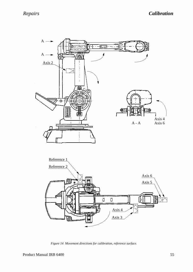
Repairs Calibration
Figure 14 Movement directions for calibration, reference surface.
Axis 5
Axis 6
Reference 2
Reference 1
Axis 3
Axis 4
Axis 2
A
A
Axis 4Axis 6A - A
Product Manual IRB 6400 55
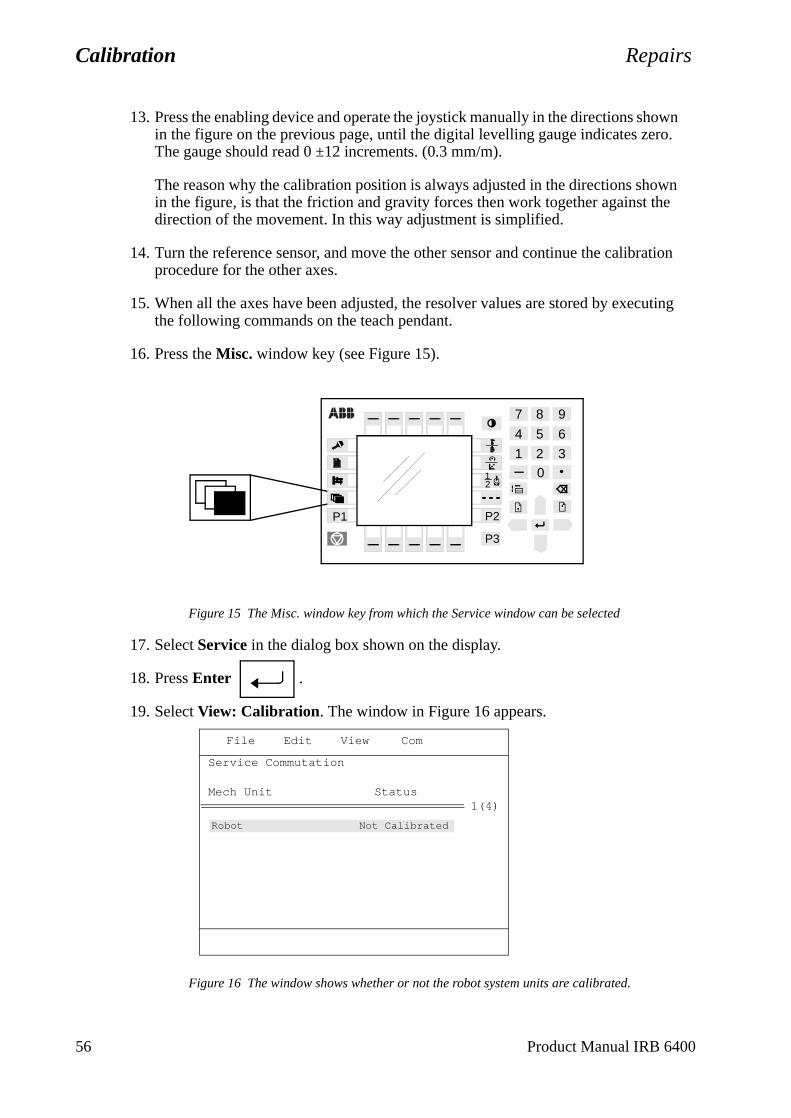
Calibration Repairs
n
ion
ting
13. Press the enabling device and operate the joystick manually in the directions shown in the figure on the previous page, until the digital levelling gauge indicates zero. The gauge should read 0 ±12 increments. (0.3 mm/m).
The reason why the calibration position is always adjusted in the directions showin the figure, is that the friction and gravity forces then work together against thedirection of the movement. In this way adjustment is simplified.
14. Turn the reference sensor, and move the other sensor and continue the calibratprocedure for the other axes.
15. When all the axes have been adjusted, the resolver values are stored by executhe following commands on the teach pendant.
16. Press the Misc. window key (see Figure 15).
Figure 15 The Misc. window key from which the Service window can be selected
17. Select Service in the dialog box shown on the display.
18. Press Enter .
19. Select View: Calibration. The window in Figure 16 appears.
Figure 16 The window shows whether or not the robot system units are calibrated.
21
2 30
1
4 5 6
7 8 9
P3
P1 P2
File Edit View Com
1(4)
Service Commutation
Mech Unit Status
Robot Not Calibrated
56 Product Manual IRB 6400
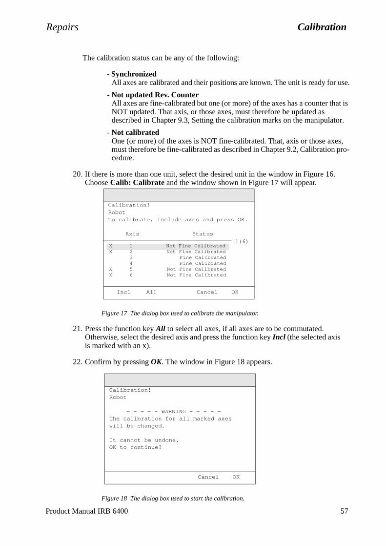
Repairs Calibration
The calibration status can be any of the following:
- SynchronizedAll axes are calibrated and their positions are known. The unit is ready for use.
- Not updated Rev. CounterAll axes are fine-calibrated but one (or more) of the axes has a counter that is NOT updated. That axis, or those axes, must therefore be updated as described in Chapter 9.3, Setting the calibration marks on the manipulator.
- Not calibratedOne (or more) of the axes is NOT fine-calibrated. That, axis or those axes, must therefore be fine-calibrated as described in Chapter 9.2, Calibration pro-cedure.
20. If there is more than one unit, select the desired unit in the window in Figure 16. Choose Calib: Calibrate and the window shown in Figure 17 will appear.
Figure 17 The dialog box used to calibrate the manipulator.
21. Press the function key All to select all axes, if all axes are to be commutated. Otherwise, select the desired axis and press the function key Incl (the selected axisis marked with an x).
22. Confirm by pressing OK. The window in Figure 18 appears.
Figure 18 The dialog box used to start the calibration.
Incl All Cancel OK
1(6)
Calibration!RobotTo calibrate, include axes and press OK.
Axis Status
X 1 Not Fine CalibratedX 2 Not Fine Calibrated
3 Fine Calibrated4 Fine Calibrated
X 5 Not Fine CalibratedX 6 Not Fine Calibrated
Cancel OK
Calibration!Robot
- - - - - WARNING - - - - -The calibration for all marked axes will be changed.
It cannot be undone.OK to continue?
Product Manual IRB 6400 57
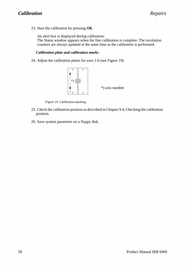
Calibration Repairs
23. Start the calibration by pressing OK.
An alert box is displayed during calibration. The Status window appears when the fine calibration is complete. The revolutioncounters are always updated at the same time as the calibration is performed.
Calibration plate and calibration marks
24. Adjust the calibration plates for axes 1-6 (see Figure 19).
Figure 19 Calibration marking.
25. Check the calibration position as described in Chapter 9.4, Checking the calibration position.
26. Save system parametrs on a floppy disk.
+
-
*)
*) axis number
58 Product Manual IRB 6400
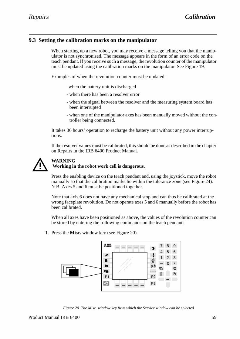
Repairs Calibration
p-
hapter
robot 4).
at the ot has
er can
9.3 Setting the calibration marks on the manipulator
When starting up a new robot, you may receive a message telling you that the manip-ulator is not synchronised. The message appears in the form of an error code on the teach pendant. If you receive such a message, the revolution counter of the manipulator must be updated using the calibration marks on the manipulator. See Figure 19.
Examples of when the revolution counter must be updated:
- when the battery unit is discharged
- when there has been a resolver error
- when the signal between the resolver and the measuring system board has been interrupted
- when one of the manipulator axes has been manually moved without the con-troller being connected.
It takes 36 hours’ operation to recharge the battery unit without any power interrutions.
If the resolver values must be calibrated, this should be done as described in the con Repairs in the IRB 6400 Product Manual.
WARNING Working in the robot work cell is dangerous.
Press the enabling device on the teach pendant and, using the joystick, move themanually so that the calibration marks lie within the tolerance zone (see Figure 2N.B. Axes 5 and 6 must be positioned together.
Note that axis 6 does not have any mechanical stop and can thus be calibrated wrong faceplate revolution. Do not operate axes 5 and 6 manually before the robbeen calibrated.
When all axes have been positioned as above, the values of the revolution countbe stored by entering the following commands on the teach pendant:
1. Press the Misc. window key (see Figure 20).
Figure 20 The Misc. window key from which the Service window can be selected
21
2 30
1
4 5 6
7 8 9
P3
P1 P2
Product Manual IRB 6400 59
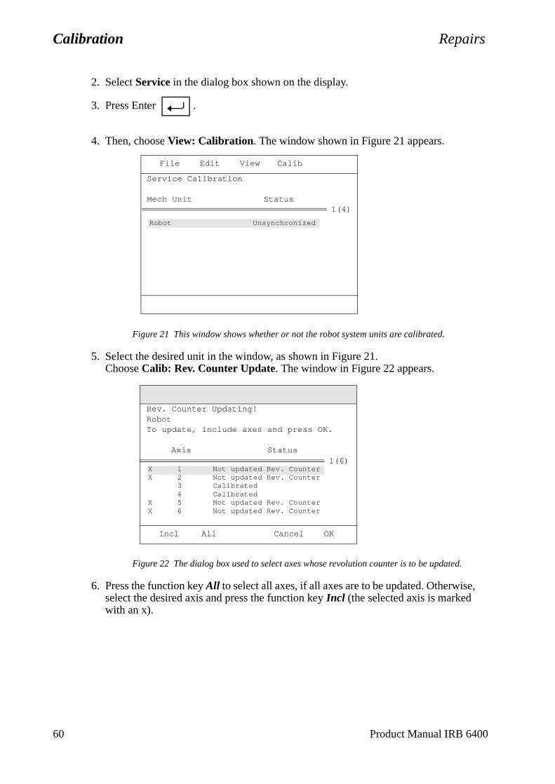
Calibration Repairs
2. Select Service in the dialog box shown on the display.
3. Press Enter .
4. Then, choose View: Calibration. The window shown in Figure 21 appears.
Figure 21 This window shows whether or not the robot system units are calibrated.
5. Select the desired unit in the window, as shown in Figure 21.Choose Calib: Rev. Counter Update. The window in Figure 22 appears.
Figure 22 The dialog box used to select axes whose revolution counter is to be updated.
6. Press the function key All to select all axes, if all axes are to be updated. Otherwise, select the desired axis and press the function key Incl (the selected axis is marked with an x).
Robot Unsynchronized
File Edit View Calib
1(4)
Service Calibration
Mech Unit Status
X 1 Not updated Rev. CounterX 2 Not updated Rev. Counter
3 Calibrated4 Calibrated
X 5 Not updated Rev. CounterX 6 Not updated Rev. Counter
Incl All Cancel OK
1(6)
Rev. Counter Updating!RobotTo update, include axes and press OK.
Axis Status
60 Product Manual IRB 6400
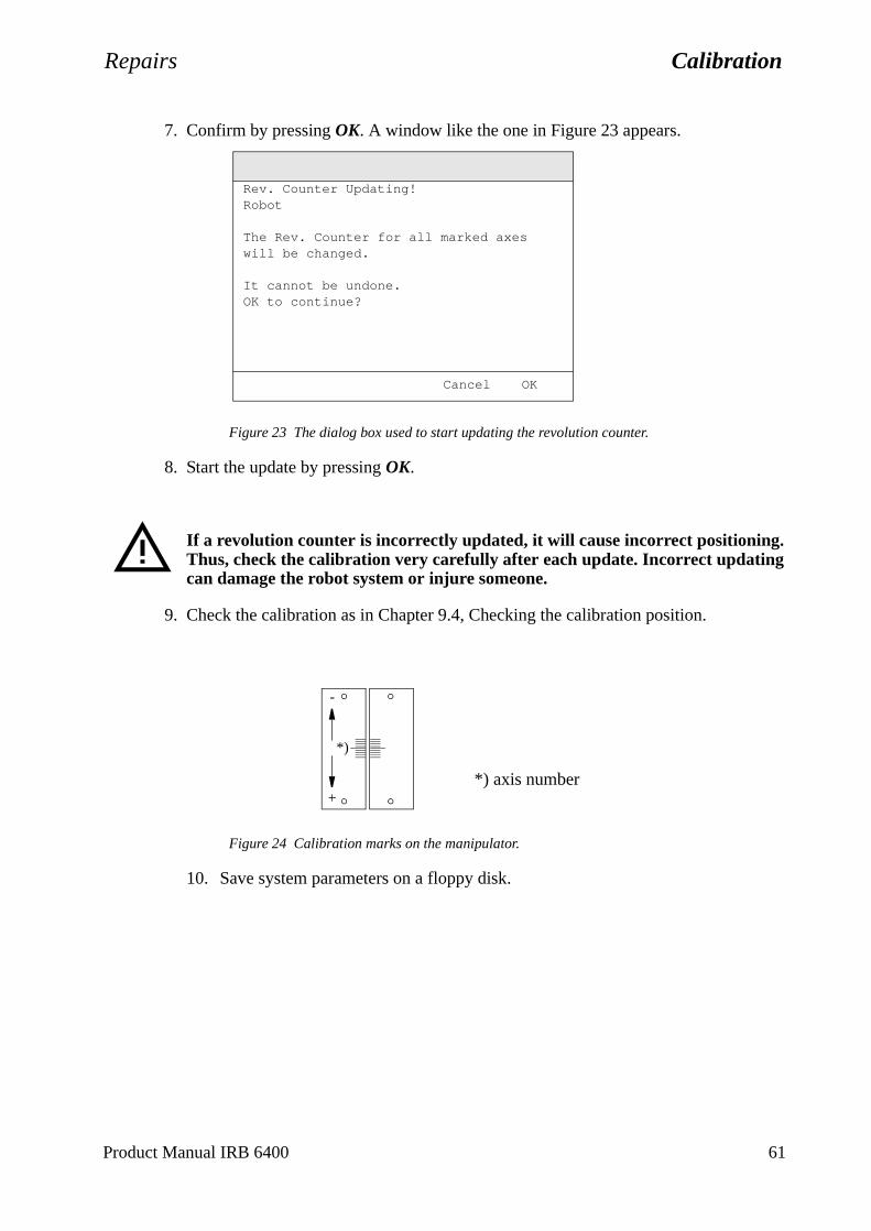
Repairs Calibration
7. Confirm by pressing OK. A window like the one in Figure 23 appears.
Figure 23 The dialog box used to start updating the revolution counter.
8. Start the update by pressing OK.
If a revolution counter is incorrectly updated, it will cause incorrect positioning. Thus, check the calibration very carefully after each update. Incorrect updating can damage the robot system or injure someone.
9. Check the calibration as in Chapter 9.4, Checking the calibration position.
Figure 24 Calibration marks on the manipulator.
10. Save system parameters on a floppy disk.
Cancel OK
Rev. Counter Updating!Robot
The Rev. Counter for all marked axes will be changed.
It cannot be undone.OK to continue?
+
-
*)
*) axis number
Product Manual IRB 6400 61
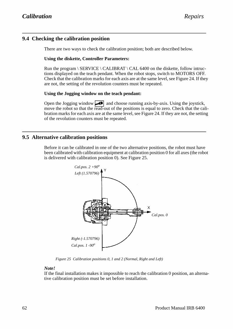
Calibration Repairs
9.4 Checking the calibration position
There are two ways to check the calibration position; both are described below.
Using the diskette, Controller Parameters:
Run the program \ SERVICE \ CALIBRAT \ CAL 6400 on the diskette, follow intruc-tions displayed on the teach pendant. When the robot stops, switch to MOTORS OFF. Check that the calibration marks for each axis are at the same level, see Figure 24. If they are not, the setting of the revolution counters must be repeated.
Using the Jogging window on the teach pendant:
Open the Jogging window and choose running axis-by-axis. Using the joystick, move the robot so that the read-out of the positions is equal to zero. Check that the cali-bration marks for each axis are at the same level, see Figure 24. If they are not, the setting of the revolution counters must be repeated.
9.5 Alternative calibration positions
Before it can be calibrated in one of the two alternative positions, the robot must have been calibrated with calibration equipment at calibration position 0 for all axes (the robot is delivered with calibration position 0). See Figure 25.
Figure 25 Calibration positions 0, 1 and 2 (Normal, Right and Left)
Note! If the final installation makes it impossible to reach the calibration 0 position, an alterna-tive calibration position must be set before installation.
Cal.pos. 0
Cal.pos. 1 -90o
Cal.pos. 2 +90o
Y
X
Left (1.570796)
Right (-1.570796)
62 Product Manual IRB 6400
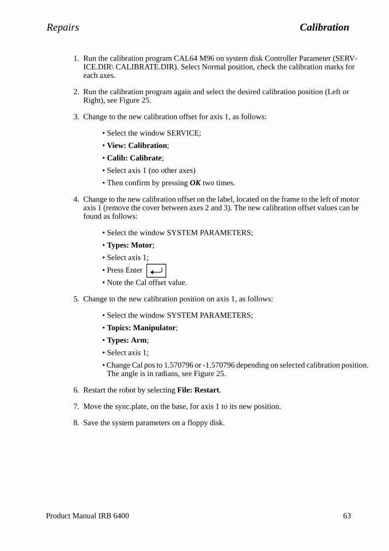
Repairs Calibration
tor be
sition.
1. Run the calibration program CAL64 M96 on system disk Controller Parameter (SERV-ICE.DIR\ CALIBRATE.DIR). Select Normal position, check the calibration marks for each axes.
2. Run the calibration program again and select the desired calibration position (Left or Right), see Figure 25.
3. Change to the new calibration offset for axis 1, as follows:
• Select the window SERVICE;
• View: Calibration;
• Calib: Calibrate;
• Select axis 1 (no other axes)
• Then confirm by pressing OK two times.
4. Change to the new calibration offset on the label, located on the frame to the left of moaxis 1 (remove the cover between axes 2 and 3). The new calibration offset values canfound as follows:
• Select the window SYSTEM PARAMETERS;
• Types: Motor;
• Select axis 1;
• Press Enter
• Note the Cal offset value.
5. Change to the new calibration position on axis 1, as follows:
• Select the window SYSTEM PARAMETERS;
• Topics: Manipulator;
• Types: Arm;
• Select axis 1;
• Change Cal pos to 1.570796 or -1.570796 depending on selected calibration poThe angle is in radians, see Figure 25.
6. Restart the robot by selecting File: Restart.
7. Move the sync.plate, on the base, for axis 1 to its new position.
8. Save the system parameters on a floppy disk.
Product Manual IRB 6400 63
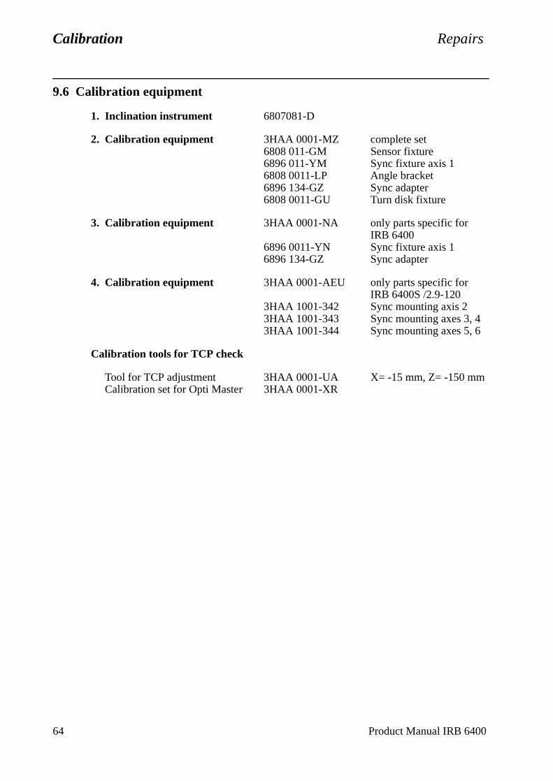
Calibration Repairs
9.6 Calibration equipment
1. Inclination instrument 6807081-D
2. Calibration equipment 3HAA 0001-MZ complete set6808 011-GM Sensor fixture6896 011-YM Sync fixture axis 16808 0011-LP Angle bracket6896 134-GZ Sync adapter6808 0011-GU Turn disk fixture
3. Calibration equipment 3HAA 0001-NA only parts specific forIRB 6400
6896 0011-YN Sync fixture axis 16896 134-GZ Sync adapter
4. Calibration equipment 3HAA 0001-AEU only parts specific forIRB 6400S /2.9-120
3HAA 1001-342 Sync mounting axis 23HAA 1001-343 Sync mounting axes 3, 43HAA 1001-344 Sync mounting axes 5, 6
Calibration tools for TCP check
Tool for TCP adjustment 3HAA 0001-UA X= -15 mm, Z= -150 mmCalibration set for Opti Master 3HAA 0001-XR
64 Product Manual IRB 6400
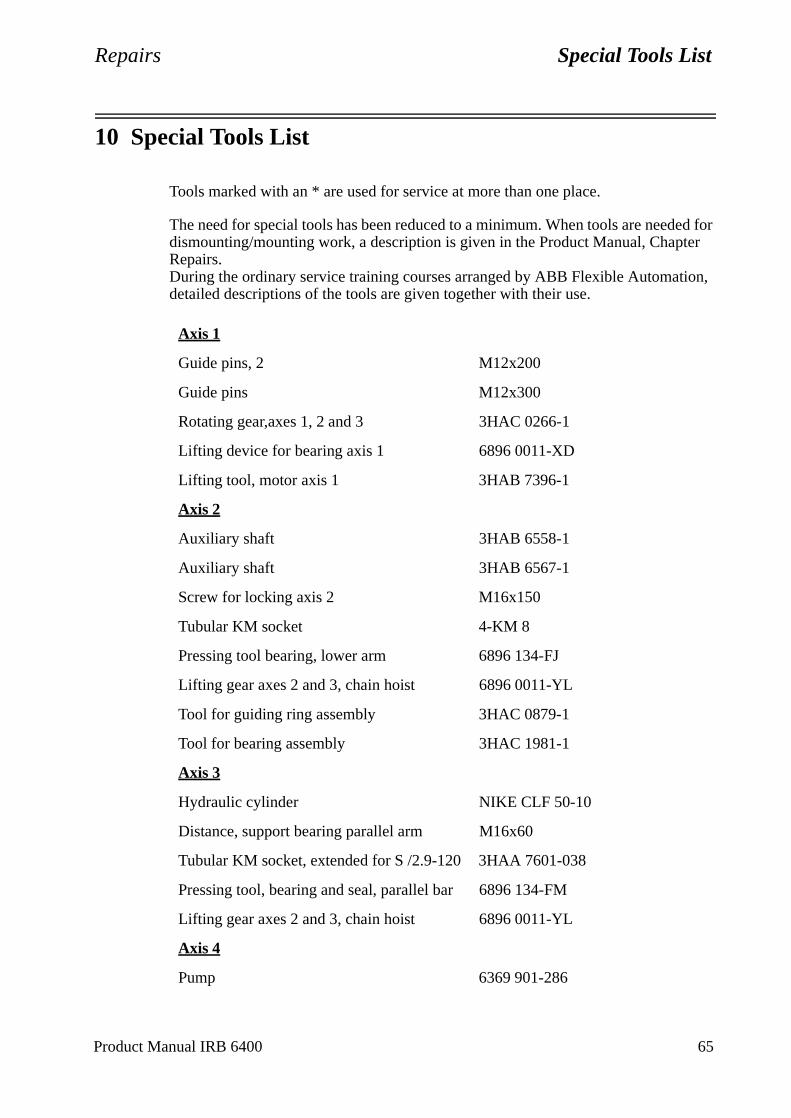
Repairs Special Tools List
10 Special Tools List
Tools marked with an * are used for service at more than one place.
The need for special tools has been reduced to a minimum. When tools are needed for dismounting/mounting work, a description is given in the Product Manual, Chapter Repairs.During the ordinary service training courses arranged by ABB Flexible Automation, detailed descriptions of the tools are given together with their use.
Axis 1
Guide pins, 2 M12x200
Guide pins M12x300
Rotating gear,axes 1, 2 and 3 3HAC 0266-1
Lifting device for bearing axis 1 6896 0011-XD
Lifting tool, motor axis 1 3HAB 7396-1
Axis 2
Auxiliary shaft 3HAB 6558-1
Auxiliary shaft 3HAB 6567-1
Screw for locking axis 2 M16x150
Tubular KM socket 4-KM 8
Pressing tool bearing, lower arm 6896 134-FJ
Lifting gear axes 2 and 3, chain hoist 6896 0011-YL
Tool for guiding ring assembly 3HAC 0879-1
Tool for bearing assembly 3HAC 1981-1
Axis 3
Hydraulic cylinder NIKE CLF 50-10
Distance, support bearing parallel arm M16x60
Tubular KM socket, extended for S /2.9-120 3HAA 7601-038
Pressing tool, bearing and seal, parallel bar 6896 134-FM
Lifting gear axes 2 and 3, chain hoist 6896 0011-YL
Axis 4
Pump 6369 901-286
Product Manual IRB 6400 65
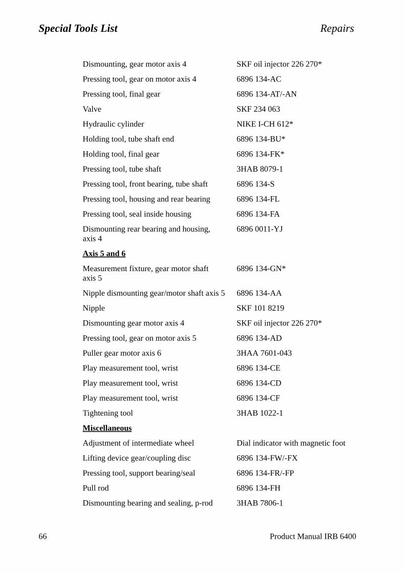
Special Tools List Repairs
Dismounting, gear motor axis 4 SKF oil injector 226 270*
Pressing tool, gear on motor axis 4 6896 134-AC
Pressing tool, final gear 6896 134-AT/-AN
Valve SKF 234 063
Hydraulic cylinder NIKE I-CH 612*
Holding tool, tube shaft end 6896 134-BU*
Holding tool, final gear 6896 134-FK*
Pressing tool, tube shaft 3HAB 8079-1
Pressing tool, front bearing, tube shaft 6896 134-S
Pressing tool, housing and rear bearing 6896 134-FL
Pressing tool, seal inside housing 6896 134-FA
Dismounting rear bearing and housing, axis 4
6896 0011-YJ
Axis 5 and 6
Measurement fixture, gear motor shaftaxis 5
6896 134-GN*
Nipple dismounting gear/motor shaft axis 5 6896 134-AA
Nipple SKF 101 8219
Dismounting gear motor axis 4 SKF oil injector 226 270*
Pressing tool, gear on motor axis 5 6896 134-AD
Puller gear motor axis 6 3HAA 7601-043
Play measurement tool, wrist 6896 134-CE
Play measurement tool, wrist 6896 134-CD
Play measurement tool, wrist 6896 134-CF
Tightening tool 3HAB 1022-1
Miscellaneous
Adjustment of intermediate wheel Dial indicator with magnetic foot
Lifting device gear/coupling disc 6896 134-FW/-FX
Pressing tool, support bearing/seal 6896 134-FR/-FP
Pull rod 6896 134-FH
Dismounting bearing and sealing, p-rod 3HAB 7806-1
66 Product Manual IRB 6400

Repairs Special Tools List
Pressing tool, seal, cover housing 6896 134-BX
Grease nipples (R 1/8”) 2545 2021-26
Calibration tool for TCP check
Tool for TCP adjustment 3HAA 0001-UAX=-15 mm, Z=-150 mm
Calibration set for Vision 3HAA 0001-XR
Tools for grease replacement, axes 1-3
Axis 1
Socket 3HAB 1561-1
Nipple 3HAA 7601-090
Hose D=18/12 mm, L=1000 mm
Hose clip D=15-20 mm
Socket Square 1/2” / hexagon 10 mm
Extender 1/2” / L=250 mm
Ratchet wrench
Axis 2-3, 6
Nipple 3HAA 7601-091
Hose D=18/12 mm, L=1000 mm
Allen key 6 mm
Balancing cylinders 3HAC 4701-1
Leaktest tools for Foundry robots
Axis 6
Test device 3HAC 0207-1
Adapter 3HAC 4618-1
Product Manual IRB 6400 67

Special Tools List Repairs
68 Product Manual IRB 6400
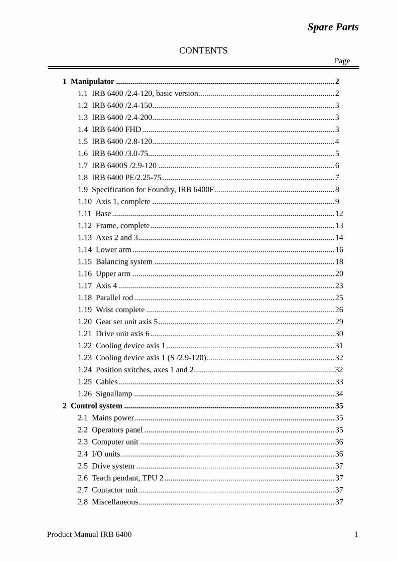
Spare Parts
CONTENTSPage
Product Manual IRB 6400 1
1 Manipulator .............................................................................................................2
1.1 IRB 6400 /2.4-120, basic version....................................................................2
1.2 IRB 6400 /2.4-150...........................................................................................3
1.3 IRB 6400 /2.4-200...........................................................................................3
1.4 IRB 6400 FHD................................................................................................3
1.5 IRB 6400 /2.8-120...........................................................................................4
1.6 IRB 6400 /3.0-75.............................................................................................5
1.7 IRB 6400S /2.9-120 ........................................................................................6
1.8 IRB 6400 PE/2.25-75......................................................................................7
1.9 Specification for Foundry, IRB 6400F............................................................8
1.10 Axis 1, complete ...........................................................................................9
1.11 Base ...............................................................................................................12
1.12 Frame, complete............................................................................................13
1.13 Axes 2 and 3..................................................................................................14
1.14 Lower arm.....................................................................................................16
1.15 Balancing system ..........................................................................................18
1.16 Upper arm .....................................................................................................20
1.17 Axis 4 ............................................................................................................23
1.18 Parallel rod ....................................................................................................25
1.19 Wrist complete ..............................................................................................26
1.20 Gear set unit axis 5........................................................................................29
1.21 Drive unit axis 6............................................................................................30
1.22 Cooling device axis 1....................................................................................31
1.23 Cooling device axis 1 (S /2.9-120)................................................................32
1.24 Position sxitches, axes 1 and 2...................................................................... 32
1.25 Cables............................................................................................................33
1.26 Signallamp ....................................................................................................34
2 Control system .........................................................................................................35
2.1 Mains power....................................................................................................35
2.2 Operators panel ...............................................................................................35
2.3 Computer unit .................................................................................................36
2.4 I/O units...........................................................................................................36
2.5 Drive system ...................................................................................................37
2.6 Teach pendant, TPU 2 .....................................................................................37
2.7 Contactor unit..................................................................................................37
2.8 Miscellaneous..................................................................................................37
Spare Parts
Spare Parts
1 Manipulator
Item numbers refer to item numbers on the foldouts.
1.1 IRB 6400 /2.4-120, basic version
Itm Qty Name Art. no. Rem
1 Label
NOTE!Following foldouts, 0:2-0:5, show the difference from the basic version.
Product Manual IRB 6400 2
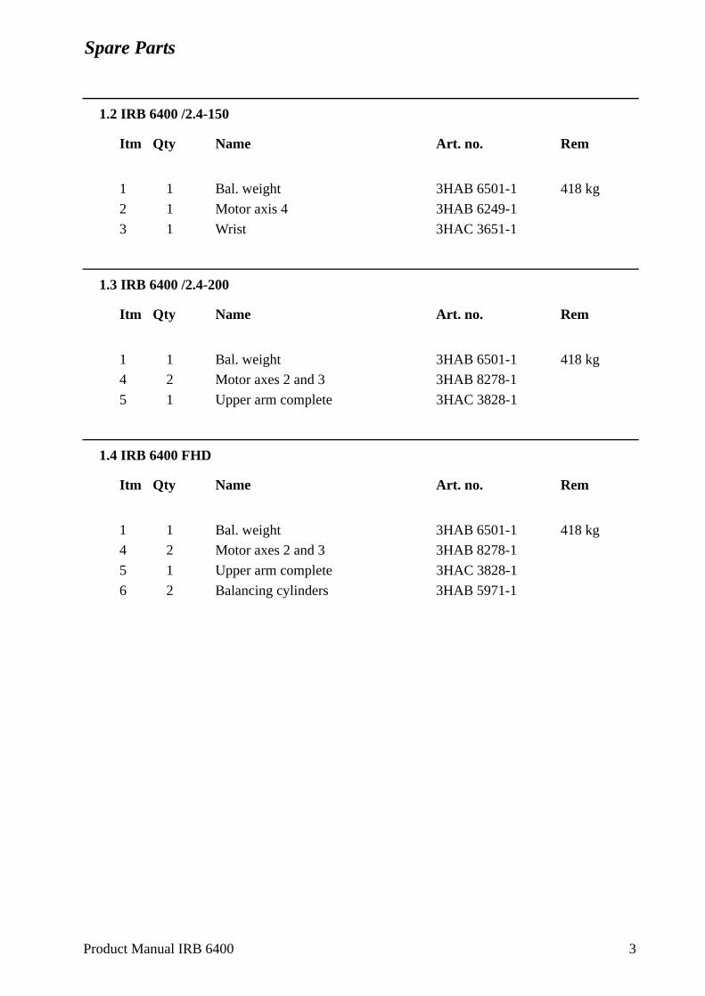
Spare Parts
1.2 IRB 6400 /2.4-150
Itm Qty Name Art. no. Rem
1 1 Bal. weight 3HAB 6501-1 418 kg
2 1 Motor axis 4 3HAB 6249-1
3 1 Wrist 3HAC 3651-1
1.3 IRB 6400 /2.4-200
Itm Qty Name Art. no. Rem
1 1 Bal. weight 3HAB 6501-1 418 kg
4 2 Motor axes 2 and 3 3HAB 8278-1
5 1 Upper arm complete 3HAC 3828-1
1.4 IRB 6400 FHD
Itm Qty Name Art. no. Rem
1 1 Bal. weight 3HAB 6501-1 418 kg
4 2 Motor axes 2 and 3 3HAB 8278-1
5 1 Upper arm complete 3HAC 3828-1
6 2 Balancing cylinders 3HAB 5971-1
Product Manual IRB 6400 3

Spare Parts
1.5 IRB 6400 /2.8-120
Itm Qty Name Art. no. Rem
1 1 Extender 3HAC 3833-1 404 mm2 1 Bal. weight 3HAB 6501-1 418 kg3 1 Cable axis 5 3HAB 6189-14 1 Cable axis 6 3HAB 6197-15 1 Cover 3HAA 1001-302
Product Manual IRB 6400 4

Spare Parts
1.6 IRB 6400 /3.0-75
Itm Qty Name Art. no. Rem
1 1 Extender 3HAC 3832-1 606 mm2 1 Bal. weight 3HAB 6501-1 418 kg3 1 Cable axis 5 3HAB 6189-14 1 Cable axis 6 3HAB 6197-15 1 Cover 3HAA 1001-305
Product Manual IRB 6400 5
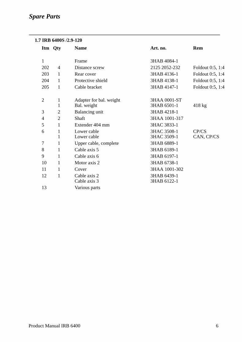
Spare Parts
1.7 IRB 6400S /2.9-120
Itm Qty Name Art. no. Rem
1 Frame 3HAB 4084-1202 4 Distance screw 2125 2052-232 Foldout 0:5, 1:4 203 1 Rear cover 3HAB 4136-1 Foldout 0:5, 1:4 204 1 Protective shield 3HAB 4138-1 Foldout 0:5, 1:4 205 1 Cable bracket 3HAB 4147-1 Foldout 0:5, 1:4
2 1 Adapter for bal. weight 3HAA 0001-ST1 Bal. weight 3HAB 6501-1 418 kg
3 2 Balancing unit 3HAB 4218-14 2 Shaft 3HAA 1001-3175 1 Extender 404 mm 3HAC 3833-16 1 Lower cable 3HAC 3508-1 CP/CS
1 Lower cable 3HAC 3509-1 CAN, CP/CS7 1 Upper cable, complete 3HAB 6889-18 1 Cable axis 5 3HAB 6189-19 1 Cable axis 6 3HAB 6197-110 1 Motor axis 2 3HAB 6738-111 1 Cover 3HAA 1001-30212 1 Cable axis 2 3HAB 6439-1
Cable axis 3 3HAB 6122-113 Various parts
Product Manual IRB 6400 6

Spare Parts
1.8 IRB 6400 PE/2.25-75
Itm Qty Name Art. no. Rem
1 1 Motor axes 1, 2 and 3 3HAB 4043-13 1 Protective plate 3HAA 1101-609 4 1 Cable upper arm 3HAB 4483-15 1 Tube shaft 3HAB 4453-16 1 Fan, cooling device for axis 1 3HAA 0001-AAB not on foldout7 1 Cover 3HAA 1001-573
Product Manual IRB 6400 7
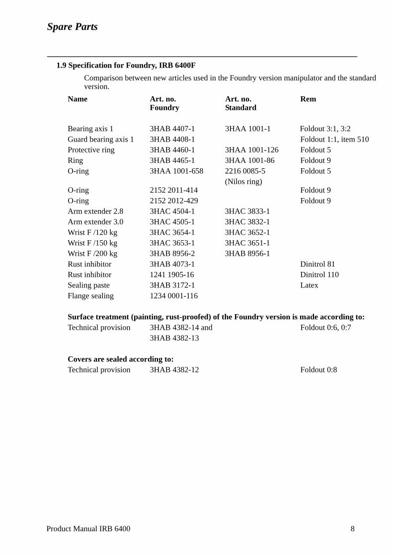
Spare Parts
1.9 Specification for Foundry, IRB 6400F
Comparison between new articles used in the Foundry version manipulator and the standard version.
Name Art. no. Art. no. RemFoundry Standard
Bearing axis 1 3HAB 4407-1 3HAA 1001-1 Foldout 3:1, 3:2Guard bearing axis 1 3HAB 4408-1 Foldout 1:1, item 510Protective ring 3HAB 4460-1 3HAA 1001-126 Foldout 5Ring 3HAB 4465-1 3HAA 1001-86 Foldout 9O-ring 3HAA 1001-658 2216 0085-5 Foldout 5
(Nilos ring)O-ring 2152 2011-414 Foldout 9O-ring 2152 2012-429 Foldout 9Arm extender 2.8 3HAC 4504-1 3HAC 3833-1Arm extender 3.0 3HAC 4505-1 3HAC 3832-1Wrist F /120 kg 3HAC 3654-1 3HAC 3652-1Wrist F /150 kg 3HAC 3653-1 3HAC 3651-1Wrist F /200 kg 3HAB 8956-2 3HAB 8956-1Rust inhibitor 3HAB 4073-1 Dinitrol 81Rust inhibitor 1241 1905-16 Dinitrol 110Sealing paste 3HAB 3172-1 LatexFlange sealing 1234 0001-116
Surface treatment (painting, rust-proofed) of the Foundry version is made according to:Technical provision 3HAB 4382-14 and Foldout 0:6, 0:7
3HAB 4382-13
Covers are sealed according to:Technical provision 3HAB 4382-12 Foldout 0:8
Product Manual IRB 6400 8
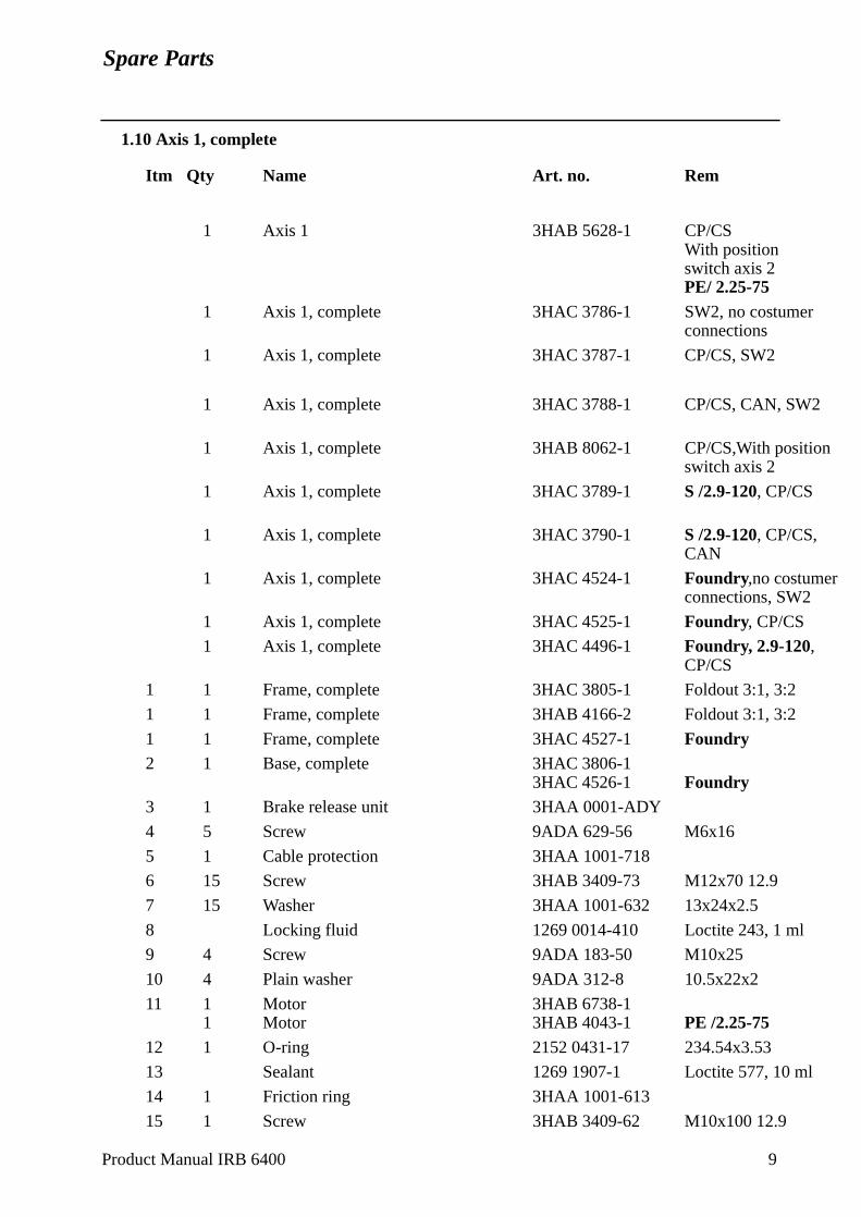
Spare Parts
1.10 Axis 1, complete
Itm Qty Name Art. no. Rem
1 Axis 1 3HAB 5628-1 CP/CSWith position switch axis 2PE/ 2.25-75
1 Axis 1, complete 3HAC 3786-1 SW2, no costumerconnections
1 Axis 1, complete 3HAC 3787-1 CP/CS, SW2
1 Axis 1, complete 3HAC 3788-1 CP/CS, CAN, SW2
1 Axis 1, complete 3HAB 8062-1 CP/CS,With positionswitch axis 2
1 Axis 1, complete 3HAC 3789-1 S /2.9-120, CP/CS
1 Axis 1, complete 3HAC 3790-1 S /2.9-120, CP/CS,CAN
1 Axis 1, complete 3HAC 4524-1 Foundry,no costumerconnections, SW2
1 Axis 1, complete 3HAC 4525-1 Foundry, CP/CS
1 Axis 1, complete 3HAC 4496-1 Foundry, 2.9-120, CP/CS
1 1 Frame, complete 3HAC 3805-1 Foldout 3:1, 3:2
1 1 Frame, complete 3HAB 4166-2 Foldout 3:1, 3:2
1 1 Frame, complete 3HAC 4527-1 Foundry2 1 Base, complete 3HAC 3806-1
3HAC 4526-1 Foundry3 1 Brake release unit 3HAA 0001-ADY
4 5 Screw 9ADA 629-56 M6x16
5 1 Cable protection 3HAA 1001-718
6 15 Screw 3HAB 3409-73 M12x70 12.9
7 15 Washer 3HAA 1001-632 13x24x2.5
8 Locking fluid 1269 0014-410 Loctite 243, 1 ml
9 4 Screw 9ADA 183-50 M10x25
10 4 Plain washer 9ADA 312-8 10.5x22x2
11 1 Motor 3HAB 6738-11 Motor 3HAB 4043-1 PE /2.25-75
12 1 O-ring 2152 0431-17 234.54x3.53
13 Sealant 1269 1907-1 Loctite 577, 10 ml
14 1 Friction ring 3HAA 1001-613
15 1 Screw 3HAB 3409-62 M10x100 12.9
Product Manual IRB 6400 9
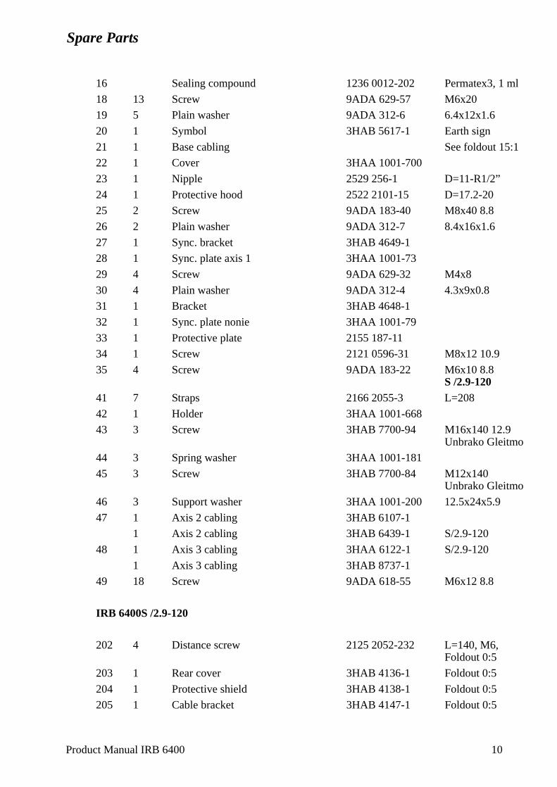
Spare Parts
16 Sealing compound 1236 0012-202 Permatex3, 1 ml
18 13 Screw 9ADA 629-57 M6x20
19 5 Plain washer 9ADA 312-6 6.4x12x1.6
20 1 Symbol 3HAB 5617-1 Earth sign
21 1 Base cabling See foldout 15:1
22 1 Cover 3HAA 1001-700
23 1 Nipple 2529 256-1 D=11-R1/2”
24 1 Protective hood 2522 2101-15 D=17.2-20
25 2 Screw 9ADA 183-40 M8x40 8.8
26 2 Plain washer 9ADA 312-7 8.4x16x1.6
27 1 Sync. bracket 3HAB 4649-1
28 1 Sync. plate axis 1 3HAA 1001-73
29 4 Screw 9ADA 629-32 M4x8
30 4 Plain washer 9ADA 312-4 4.3x9x0.8
31 1 Bracket 3HAB 4648-1
32 1 Sync. plate nonie 3HAA 1001-79
33 1 Protective plate 2155 187-11
34 1 Screw 2121 0596-31 M8x12 10.9
35 4 Screw 9ADA 183-22 M6x10 8.8S /2.9-120
41 7 Straps 2166 2055-3 L=208
42 1 Holder 3HAA 1001-668
43 3 Screw 3HAB 7700-94 M16x140 12.9Unbrako Gleitmo
44 3 Spring washer 3HAA 1001-181
45 3 Screw 3HAB 7700-84 M12x140Unbrako Gleitmo
46 3 Support washer 3HAA 1001-200 12.5x24x5.9
47 1 Axis 2 cabling 3HAB 6107-1
1 Axis 2 cabling 3HAB 6439-1 S/2.9-120
48 1 Axis 3 cabling 3HAA 6122-1 S/2.9-120
1 Axis 3 cabling 3HAB 8737-1
49 18 Screw 9ADA 618-55 M6x12 8.8
IRB 6400S /2.9-120
202 4 Distance screw 2125 2052-232 L=140, M6, Foldout 0:5
203 1 Rear cover 3HAB 4136-1 Foldout 0:5
204 1 Protective shield 3HAB 4138-1 Foldout 0:5
205 1 Cable bracket 3HAB 4147-1 Foldout 0:5
Product Manual IRB 6400 10
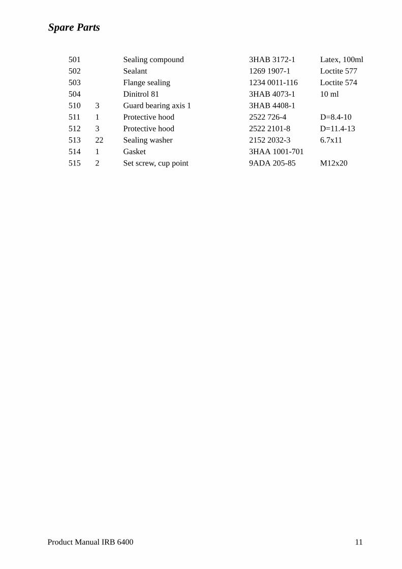
Spare Parts
501 Sealing compound 3HAB 3172-1 Latex, 100ml
502 Sealant 1269 1907-1 Loctite 577
503 Flange sealing 1234 0011-116 Loctite 574
504 Dinitrol 81 3HAB 4073-1 10 ml
510 3 Guard bearing axis 1 3HAB 4408-1
511 1 Protective hood 2522 726-4 D=8.4-10
512 3 Protective hood 2522 2101-8 D=11.4-13
513 22 Sealing washer 2152 2032-3 6.7x11
514 1 Gasket 3HAA 1001-701
515 2 Set screw, cup point 9ADA 205-85 M12x20
Product Manual IRB 6400 11
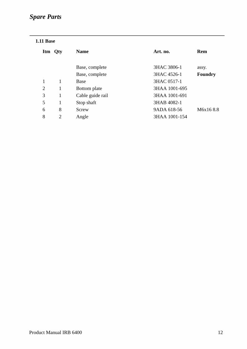
Spare Parts
1.11 Base
Itm Qty Name Art. no. Rem
Base, complete 3HAC 3806-1 assy.
Base, complete 3HAC 4526-1 Foundry1 1 Base 3HAC 0517-1
2 1 Bottom plate 3HAA 1001-695
3 1 Cable guide rail 3HAA 1001-691
5 1 Stop shaft 3HAB 4082-1
6 8 Screw 9ADA 618-56 M6x16 8.8
8 2 Angle 3HAA 1001-154
Product Manual IRB 6400 12
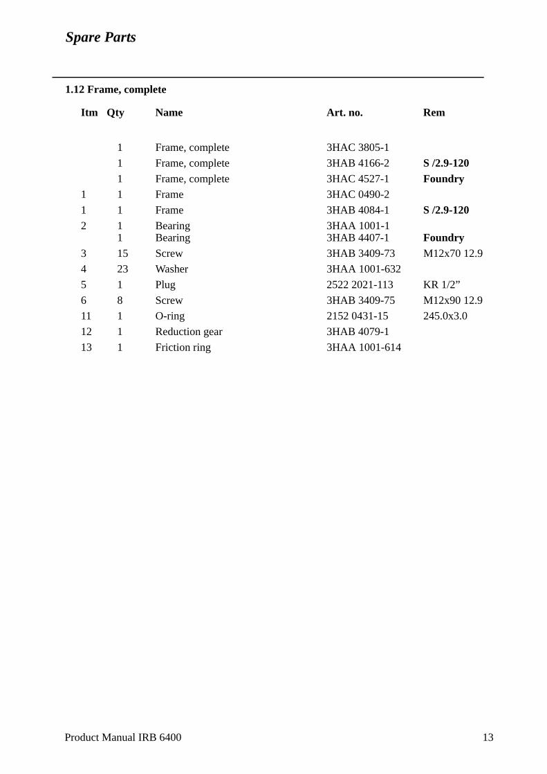
Spare Parts
1.12 Frame, complete
Itm Qty Name Art. no. Rem
1 Frame, complete 3HAC 3805-1
1 Frame, complete 3HAB 4166-2 S /2.9-1201 Frame, complete 3HAC 4527-1 Foundry
1 1 Frame 3HAC 0490-2
1 1 Frame 3HAB 4084-1 S /2.9-1202 1 Bearing 3HAA 1001-1
1 Bearing 3HAB 4407-1 Foundry3 15 Screw 3HAB 3409-73 M12x70 12.9
4 23 Washer 3HAA 1001-632
5 1 Plug 2522 2021-113 KR 1/2”
6 8 Screw 3HAB 3409-75 M12x90 12.9
11 1 O-ring 2152 0431-15 245.0x3.0
12 1 Reduction gear 3HAB 4079-1
13 1 Friction ring 3HAA 1001-614
Product Manual IRB 6400 13
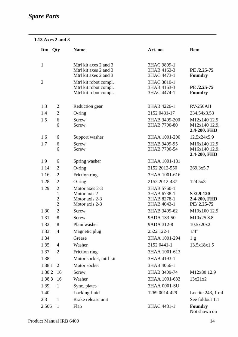
Spare Parts
1.13 Axes 2 and 3
Itm Qty Name Art. no. Rem
1 Mtrl kit axes 2 and 3 3HAC 3809-1Mtrl kit axes 2 and 3 3HAB 4162-3 PE /2.25-75Mtrl kit axes 2 and 3 3HAC 4473-1 Foundry
2 Mtrl kit robot compl. 3HAC 3810-1Mtrl kit robot compl. 3HAB 4163-3 PE /2.25-75Mtrl kit robot compl. 3HAC 4474-1 Foundry
1.3 2 Reduction gear 3HAB 4226-1 RV-250AII
1.4 2 O-ring 2152 0431-17 234.54x3.53
1.5 6 Screw 3HAB 3409-200 M12x140 12.96 Screw 3HAB 7700-80 M12x140 12.9,
2.4-200, FHD1.6 6 Support washer 3HAA 1001-200 12.5x24x5.9
1.7 6 Screw 3HAB 3409-95 M16x140 12.96 Screw 3HAB 7700-54 M16x140 12.9,
2.4-200, FHD1.9 6 Spring washer 3HAA 1001-181
1.14 2 O-ring 2152 2012-550 269.3x5.7
1.16 2 Friction ring 3HAA 1001-616
1.28 2 O-ring 2152 2012-437 124.5x3
1.29 2 Motor axes 2-3 3HAB 5760-11 Motor axis 2 3HAB 6738-1 S /2.9-1202 Motor axis 2-3 3HAB 8278-1 2.4-200, FHD2 Motor axis 2-3 3HAB 4043-1 PE/ 2.25-75
1.30 2 Screw 3HAB 3409-62 M10x100 12.9
1.31 8 Screw 9ADA 183-50 M10x25 8.8
1.32 8 Plain washer 9ADA 312-8 10.5x20x2
1.33 4 Magnetic plug 2522 122-1 1/4”
1.34 Grease 3HAA 1001-294 1 g
1.35 4 Washer 2152 0441-1 13.5x18x1.5
1.37 2 Friction ring 3HAA 1001-613
1.38 Motor socket, mtrl kit 3HAB 4193-1
1.38.1 2 Motor socket 3HAB 4056-1
1.38.2 16 Screw 3HAB 3409-74 M12x80 12.9
1.38.3 16 Washer 3HAA 1001-632 13x21x2
1.39 1 Sync. plates 3HAA 0001-SU
1.40 Locking fluid 1269 0014-429 Loctite 243, 1 ml
2.3 1 Brake release unit See foldout 1:1
2.506 1 Flap 3HAC 4481-1 FoundryNot shown on
Product Manual IRB 6400 14
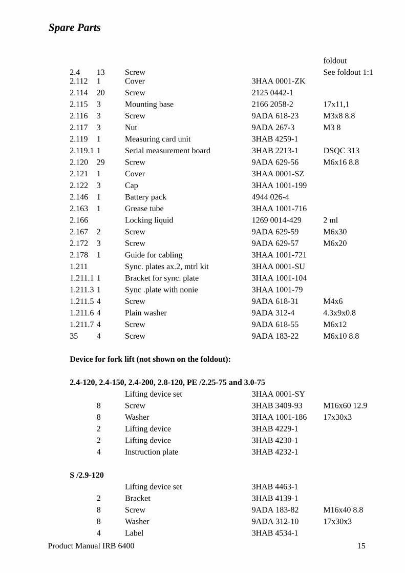
Spare Parts
foldout
2.4 13 Screw See foldout 1:12.112 1 Cover 3HAA 0001-ZK
2.114 20 Screw 2125 0442-1
2.115 3 Mounting base 2166 2058-2 17x11,1
2.116 3 Screw 9ADA 618-23 M3x8 8.8
2.117 3 Nut 9ADA 267-3 M3 8
2.119 1 Measuring card unit 3HAB 4259-1
2.119.1 1 Serial measurement board 3HAB 2213-1 DSQC 313
2.120 29 Screw 9ADA 629-56 M6x16 8.8
2.121 1 Cover 3HAA 0001-SZ
2.122 3 Cap 3HAA 1001-199
2.146 1 Battery pack 4944 026-4
2.163 1 Grease tube 3HAA 1001-716
2.166 Locking liquid 1269 0014-429 2 ml
2.167 2 Screw 9ADA 629-59 M6x30
2.172 3 Screw 9ADA 629-57 M6x20
2.178 1 Guide for cabling 3HAA 1001-721
1.211 Sync. plates ax.2, mtrl kit 3HAA 0001-SU
1.211.1 1 Bracket for sync. plate 3HAA 1001-104
1.211.3 1 Sync .plate with nonie 3HAA 1001-79
1.211.5 4 Screw 9ADA 618-31 M4x6
1.211.6 4 Plain washer 9ADA 312-4 4.3x9x0.8
1.211.7 4 Screw 9ADA 618-55 M6x12
35 4 Screw 9ADA 183-22 M6x10 8.8
Device for fork lift (not shown on the foldout):
2.4-120, 2.4-150, 2.4-200, 2.8-120, PE /2.25-75 and 3.0-75Lifting device set 3HAA 0001-SY
8 Screw 3HAB 3409-93 M16x60 12.9
8 Washer 3HAA 1001-186 17x30x3
2 Lifting device 3HAB 4229-1
2 Lifting device 3HAB 4230-1
4 Instruction plate 3HAB 4232-1
S /2.9-120Lifting device set 3HAB 4463-1
2 Bracket 3HAB 4139-1
8 Screw 9ADA 183-82 M16x40 8.8
8 Washer 9ADA 312-10 17x30x3
4 Label 3HAB 4534-1
Product Manual IRB 6400 15
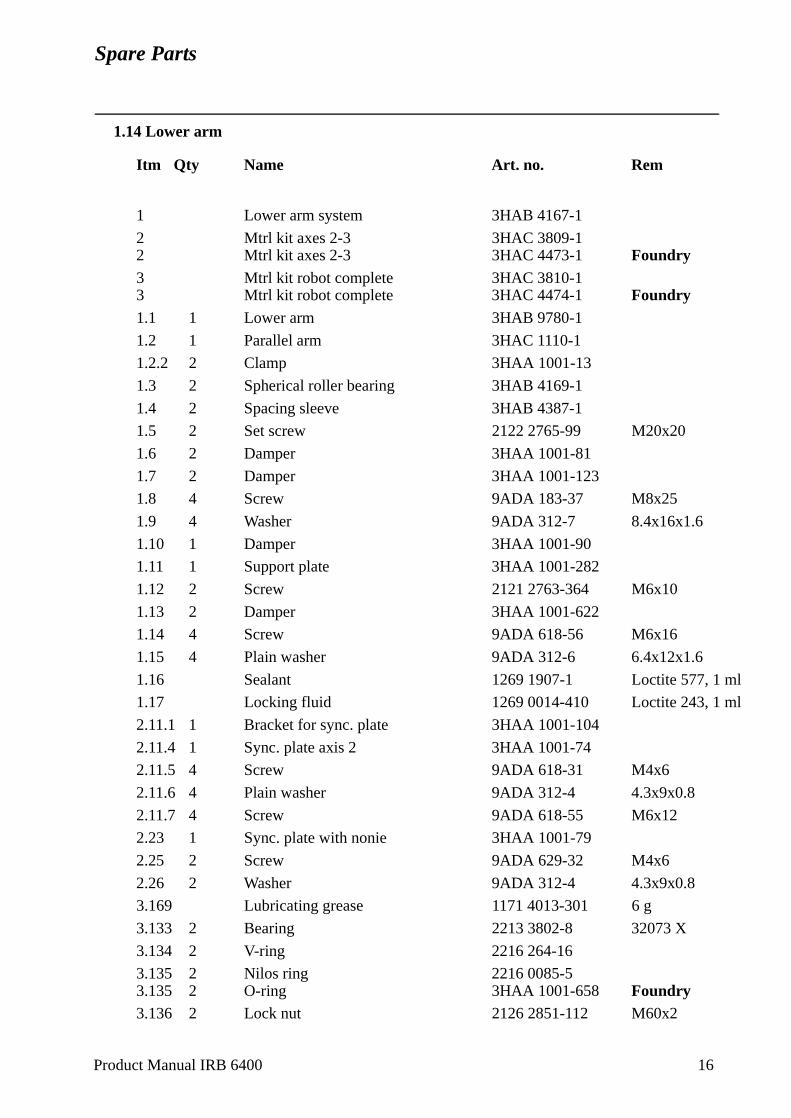
Spare Parts
1.14 Lower arm
Itm Qty Name Art. no. Rem
1 Lower arm system 3HAB 4167-1
2 Mtrl kit axes 2-3 3HAC 3809-12 Mtrl kit axes 2-3 3HAC 4473-1 Foundry3 Mtrl kit robot complete 3HAC 3810-13 Mtrl kit robot complete 3HAC 4474-1 Foundry1.1 1 Lower arm 3HAB 9780-1
1.2 1 Parallel arm 3HAC 1110-1
1.2.2 2 Clamp 3HAA 1001-13
1.3 2 Spherical roller bearing 3HAB 4169-1
1.4 2 Spacing sleeve 3HAB 4387-1
1.5 2 Set screw 2122 2765-99 M20x20
1.6 2 Damper 3HAA 1001-81
1.7 2 Damper 3HAA 1001-123
1.8 4 Screw 9ADA 183-37 M8x25
1.9 4 Washer 9ADA 312-7 8.4x16x1.6
1.10 1 Damper 3HAA 1001-90
1.11 1 Support plate 3HAA 1001-282
1.12 2 Screw 2121 2763-364 M6x10
1.13 2 Damper 3HAA 1001-622
1.14 4 Screw 9ADA 618-56 M6x16
1.15 4 Plain washer 9ADA 312-6 6.4x12x1.6
1.16 Sealant 1269 1907-1 Loctite 577, 1 ml
1.17 Locking fluid 1269 0014-410 Loctite 243, 1 ml
2.11.1 1 Bracket for sync. plate 3HAA 1001-104
2.11.4 1 Sync. plate axis 2 3HAA 1001-74
2.11.5 4 Screw 9ADA 618-31 M4x6
2.11.6 4 Plain washer 9ADA 312-4 4.3x9x0.8
2.11.7 4 Screw 9ADA 618-55 M6x12
2.23 1 Sync. plate with nonie 3HAA 1001-79
2.25 2 Screw 9ADA 629-32 M4x6
2.26 2 Washer 9ADA 312-4 4.3x9x0.8
3.169 Lubricating grease 1171 4013-301 6 g
3.133 2 Bearing 2213 3802-8 32073 X
3.134 2 V-ring 2216 264-16
3.135 2 Nilos ring 2216 0085-53.135 2 O-ring 3HAA 1001-658 Foundry3.136 2 Lock nut 2126 2851-112 M60x2
Product Manual IRB 6400 16
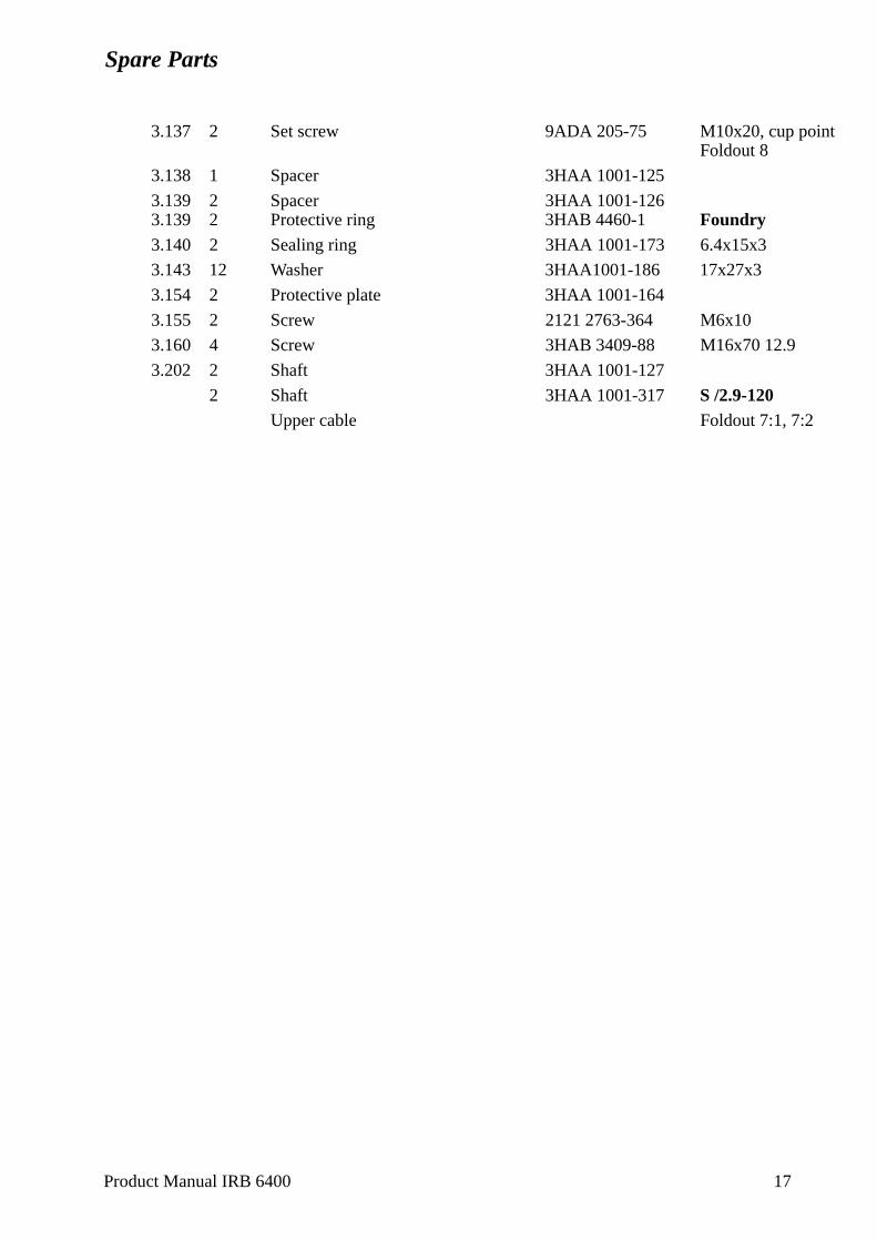
Spare Parts
3.137 2 Set screw 9ADA 205-75 M10x20, cup pointFoldout 8
3.138 1 Spacer 3HAA 1001-125
3.139 2 Spacer 3HAA 1001-1263.139 2 Protective ring 3HAB 4460-1 Foundry3.140 2 Sealing ring 3HAA 1001-173 6.4x15x3
3.143 12 Washer 3HAA1001-186 17x27x3
3.154 2 Protective plate 3HAA 1001-164
3.155 2 Screw 2121 2763-364 M6x10
3.160 4 Screw 3HAB 3409-88 M16x70 12.9
3.202 2 Shaft 3HAA 1001-127
2 Shaft 3HAA 1001-317 S /2.9-120Upper cable Foldout 7:1, 7:2
Product Manual IRB 6400 17
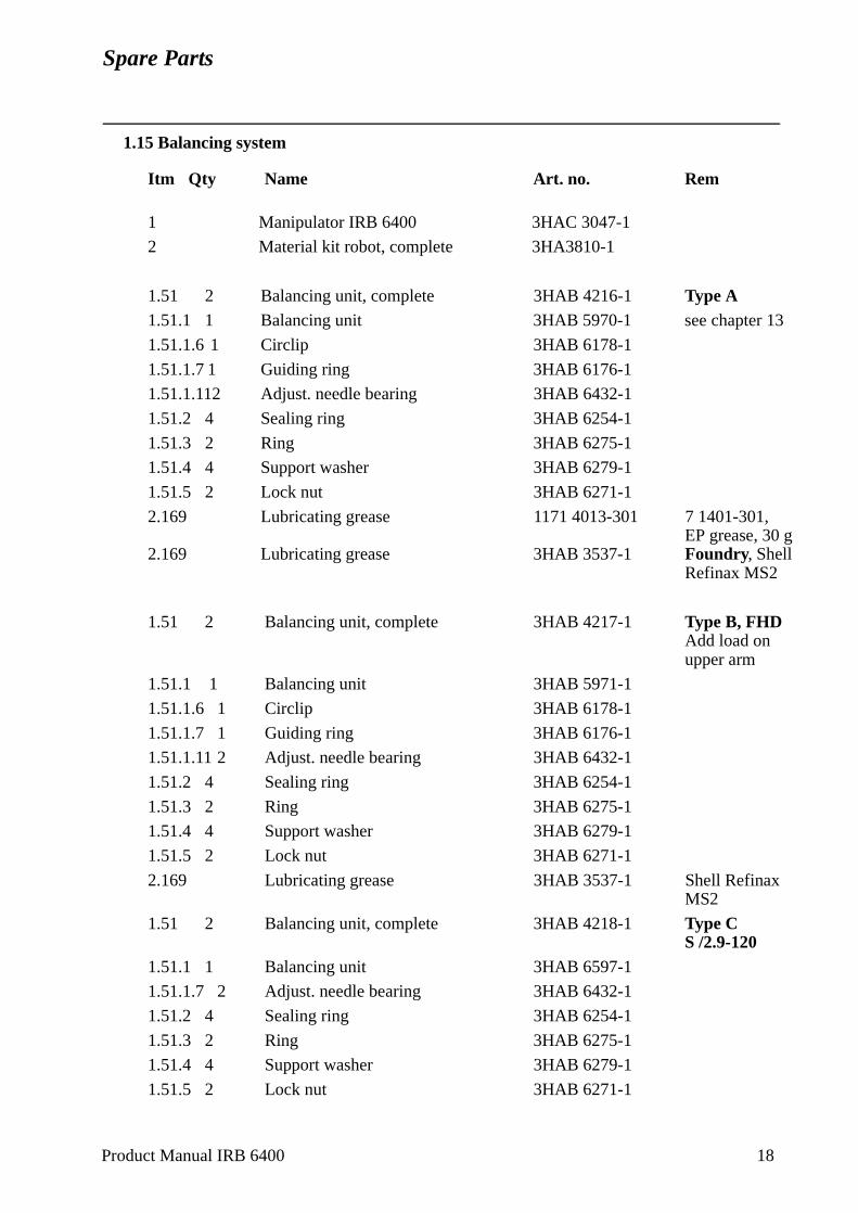
Spare Parts
1.15 Balancing system
Itm Qty Name Art. no. Rem
1 Manipulator IRB 6400 3HAC 3047-1
2 Material kit robot, complete 3HA3810-1
1.51 2 Balancing unit, complete 3HAB 4216-1 Type A1.51.1 1 Balancing unit 3HAB 5970-1 see chapter 13
1.51.1.6 1 Circlip 3HAB 6178-1
1.51.1.7 1 Guiding ring 3HAB 6176-1
1.51.1.112 Adjust. needle bearing 3HAB 6432-1
1.51.2 4 Sealing ring 3HAB 6254-1
1.51.3 2 Ring 3HAB 6275-1
1.51.4 4 Support washer 3HAB 6279-1
1.51.5 2 Lock nut 3HAB 6271-1
2.169 Lubricating grease 1171 4013-301 7 1401-301, EP grease, 30 g
2.169 Lubricating grease 3HAB 3537-1 Foundry, Shell Refinax MS2
1.51 2 Balancing unit, complete 3HAB 4217-1 Type B, FHDAdd load onupper arm
1.51.1 1 Balancing unit 3HAB 5971-1
1.51.1.6 1 Circlip 3HAB 6178-1
1.51.1.7 1 Guiding ring 3HAB 6176-1
1.51.1.11 2 Adjust. needle bearing 3HAB 6432-1
1.51.2 4 Sealing ring 3HAB 6254-1
1.51.3 2 Ring 3HAB 6275-1
1.51.4 4 Support washer 3HAB 6279-1
1.51.5 2 Lock nut 3HAB 6271-1
2.169 Lubricating grease 3HAB 3537-1 Shell Refinax MS2
1.51 2 Balancing unit, complete 3HAB 4218-1 Type CS /2.9-120
1.51.1 1 Balancing unit 3HAB 6597-1
1.51.1.7 2 Adjust. needle bearing 3HAB 6432-1
1.51.2 4 Sealing ring 3HAB 6254-1
1.51.3 2 Ring 3HAB 6275-1
1.51.4 4 Support washer 3HAB 6279-1
1.51.5 2 Lock nut 3HAB 6271-1
Product Manual IRB 6400 18
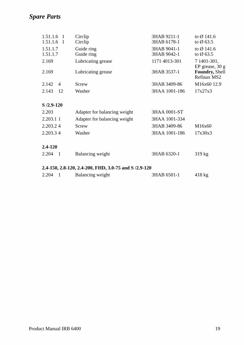
Spare Parts
1.51.1.6 1 Circlip 3HAB 9211-1 to Ø 141.61.51.1.6 1 Circlip 3HAB 6178-1 to Ø 63.5
1.51.1.7 Guide ring 3HAB 9041-1 to Ø 141.61.51.1.7 Guide ring 3HAB 9042-1 to Ø 63.5
2.169 Lubricating grease 1171 4013-301 7 1401-301, EP grease, 30 g
2.169 Lubricating grease 3HAB 3537-1 Foundry, Shell Refinax MS2
2.142 4 Screw 3HAB 3409-86 M16x60 12.9
2.143 12 Washer 3HAA 1001-186 17x27x3
S /2.9-1202.203 Adapter for balancing weight 3HAA 0001-ST
2.203.1 1 Adapter for balancing weight 3HAA 1001-334
2.203.2 4 Screw 3HAB 3409-86 M16x60
2.203.3 4 Washer 3HAA 1001-186 17x30x3
2.4-1202.204 1 Balancing weight 3HAB 6320-1 319 kg
2.4-150, 2.8-120, 2.4-200, FHD, 3.0-75 and S /2.9-1202.204 1 Balancing weight 3HAB 6501-1 418 kg
Product Manual IRB 6400 19
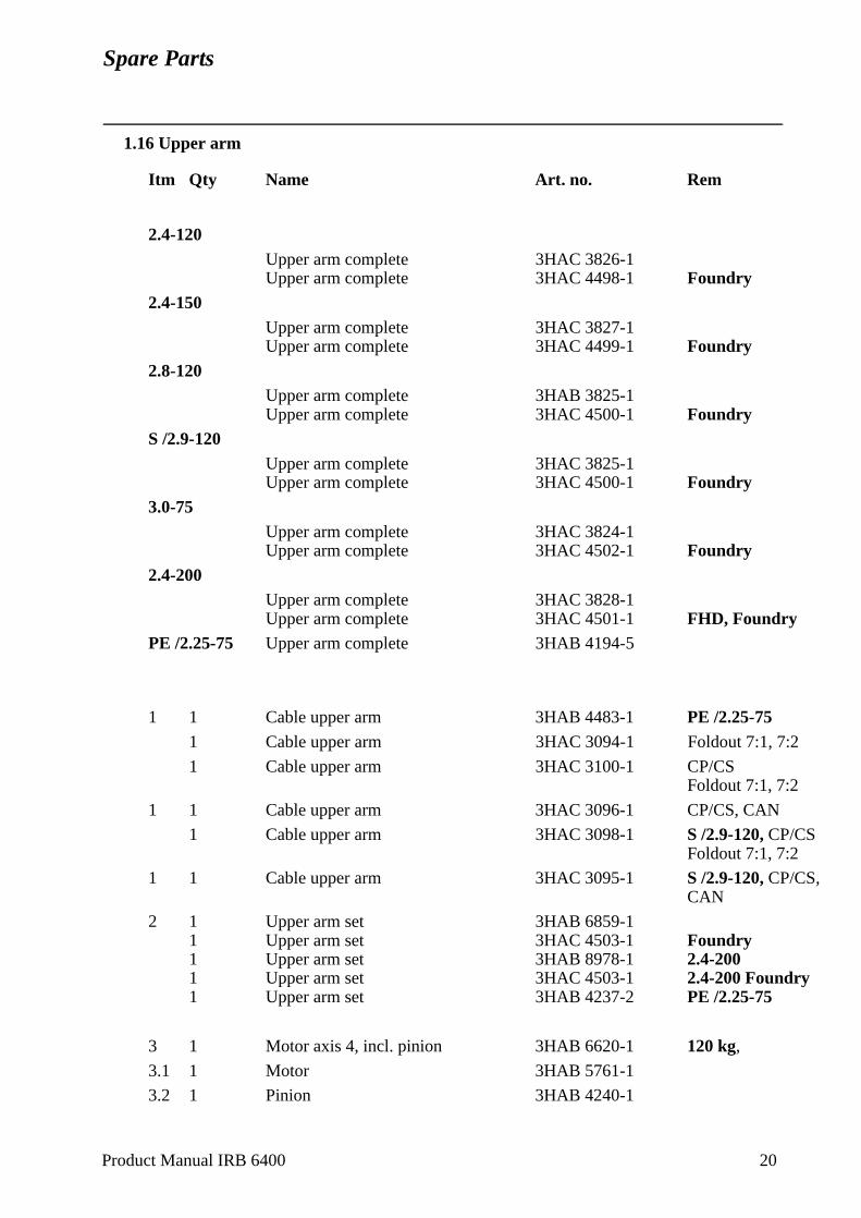
Spare Parts
1.16 Upper arm
Itm Qty Name Art. no. Rem
2.4-120Upper arm complete 3HAC 3826-1Upper arm complete 3HAC 4498-1 Foundry
2.4-150Upper arm complete 3HAC 3827-1Upper arm complete 3HAC 4499-1 Foundry
2.8-120Upper arm complete 3HAB 3825-1Upper arm complete 3HAC 4500-1 Foundry
S /2.9-120Upper arm complete 3HAC 3825-1Upper arm complete 3HAC 4500-1 Foundry
3.0-75Upper arm complete 3HAC 3824-1Upper arm complete 3HAC 4502-1 Foundry
2.4-200Upper arm complete 3HAC 3828-1Upper arm complete 3HAC 4501-1 FHD, Foundry
PE /2.25-75 Upper arm complete 3HAB 4194-5
1 1 Cable upper arm 3HAB 4483-1 PE /2.25-751 Cable upper arm 3HAC 3094-1 Foldout 7:1, 7:2
1 Cable upper arm 3HAC 3100-1 CP/CSFoldout 7:1, 7:2
1 1 Cable upper arm 3HAC 3096-1 CP/CS, CAN
1 Cable upper arm 3HAC 3098-1 S /2.9-120, CP/CSFoldout 7:1, 7:2
1 1 Cable upper arm 3HAC 3095-1 S /2.9-120, CP/CS,CAN
2 1 Upper arm set 3HAB 6859-11 Upper arm set 3HAC 4503-1 Foundry1 Upper arm set 3HAB 8978-1 2.4-2001 Upper arm set 3HAC 4503-1 2.4-200 Foundry1 Upper arm set 3HAB 4237-2 PE /2.25-75
3 1 Motor axis 4, incl. pinion 3HAB 6620-1 120 kg,
3.1 1 Motor 3HAB 5761-1
3.2 1 Pinion 3HAB 4240-1
Product Manual IRB 6400 20
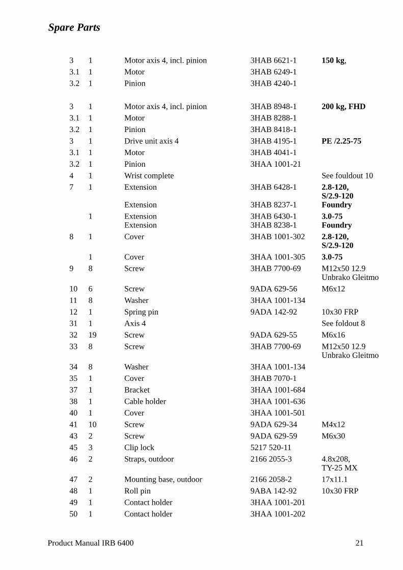
Spare Parts
3 1 Motor axis 4, incl. pinion 3HAB 6621-1 150 kg,
3.1 1 Motor 3HAB 6249-1
3.2 1 Pinion 3HAB 4240-1
3 1 Motor axis 4, incl. pinion 3HAB 8948-1 200 kg, FHD3.1 1 Motor 3HAB 8288-1
3.2 1 Pinion 3HAB 8418-1
3 1 Drive unit axis 4 3HAB 4195-1 PE /2.25-753.1 1 Motor 3HAB 4041-1
3.2 1 Pinion 3HAA 1001-21
4 1 Wrist complete See fouldout 10
7 1 Extension 3HAB 6428-1 2.8-120, S/2.9-120
Extension 3HAB 8237-1 Foundry1 Extension 3HAB 6430-1 3.0-75
Extension 3HAB 8238-1 Foundry8 1 Cover 3HAB 1001-302 2.8-120,
S/2.9-1201 Cover 3HAA 1001-305 3.0-75
9 8 Screw 3HAB 7700-69 M12x50 12.9Unbrako Gleitmo
10 6 Screw 9ADA 629-56 M6x12
11 8 Washer 3HAA 1001-134
12 1 Spring pin 9ADA 142-92 10x30 FRP
31 1 Axis 4 See foldout 8
32 19 Screw 9ADA 629-55 M6x16
33 8 Screw 3HAB 7700-69 M12x50 12.9Unbrako Gleitmo
34 8 Washer 3HAA 1001-134
35 1 Cover 3HAB 7070-1
37 1 Bracket 3HAA 1001-684
38 1 Cable holder 3HAA 1001-636
40 1 Cover 3HAA 1001-501
41 10 Screw 9ADA 629-34 M4x12
43 2 Screw 9ADA 629-59 M6x30
45 3 Clip lock 5217 520-11
46 2 Straps, outdoor 2166 2055-3 4.8x208,TY-25 MX
47 2 Mounting base, outdoor 2166 2058-2 17x11.1
48 1 Roll pin 9ABA 142-92 10x30 FRP
49 1 Contact holder 3HAA 1001-201
50 1 Contact holder 3HAA 1001-202
Product Manual IRB 6400 21

Spare Parts
55 1 Strap, outdoor 2166 2055-4 4.8x290
57 4 Screw 9ADA 629-32 M4x8
59 8 Screw 9ADA 629-56 M6x16
101 1 Cabling upper See foldout 15
102 1 Cover 3HAA 1001-161
103 1 Cover 3HAA 1001-719
104 6 Screw 9ADA 629-55 M6x12
106 1 Cover 3HAA 1001-176
107 3 Screw 9ADA 629-56 M6x16
108 3 Washer 9ADA 312-6 6.4x12x1.6
202 1 Nipple 2529 256-1 R1/2”
203 1 Cover 3HAA 1001-176
204 3 Screw 9ADA 629-56 M6x16
205 3 Washer 9ADA 312-6 6.4x12x1.6
206 1 Cover 3HAA 0001-ZB
207 4 Screw 9ADA 629-55 M6x12
208 1 Protective hood 2522 2101-15 D=17.2-20
209 Sealant 1269 0014-412 Loctite 542, 1 ml
210 2 Screw 9ADA 629-58 M6x25
Product Manual IRB 6400 22
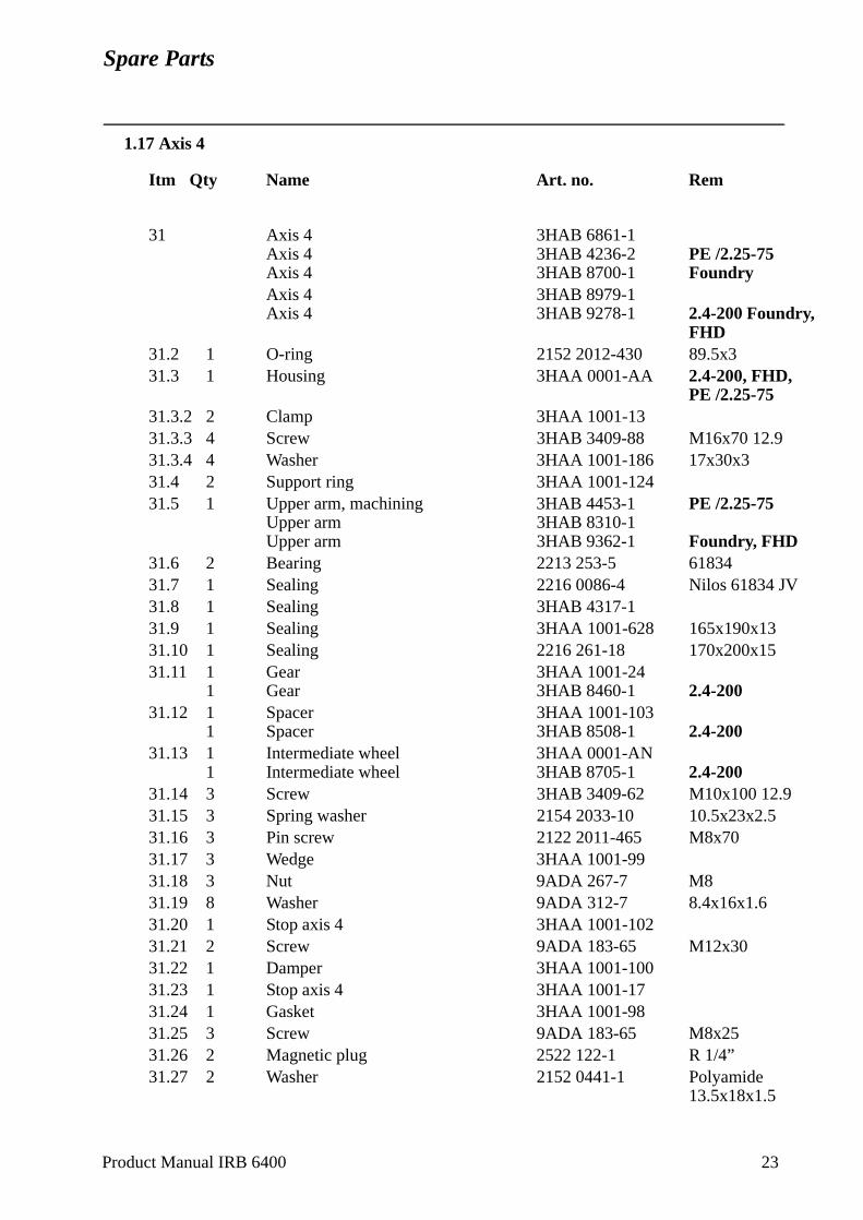
Spare Parts
1.17 Axis 4
Itm Qty Name Art. no. Rem
31 Axis 4 3HAB 6861-1Axis 4 3HAB 4236-2 PE /2.25-75Axis 4 3HAB 8700-1 FoundryAxis 4 3HAB 8979-1Axis 4 3HAB 9278-1 2.4-200 Foundry,
FHD31.2 1 O-ring 2152 2012-430 89.5x331.3 1 Housing 3HAA 0001-AA 2.4-200, FHD,
PE /2.25-7531.3.2 2 Clamp 3HAA 1001-1331.3.3 4 Screw 3HAB 3409-88 M16x70 12.931.3.4 4 Washer 3HAA 1001-186 17x30x331.4 2 Support ring 3HAA 1001-12431.5 1 Upper arm, machining 3HAB 4453-1 PE /2.25-75
Upper arm 3HAB 8310-1Upper arm 3HAB 9362-1 Foundry, FHD
31.6 2 Bearing 2213 253-5 6183431.7 1 Sealing 2216 0086-4 Nilos 61834 JV31.8 1 Sealing 3HAB 4317-131.9 1 Sealing 3HAA 1001-628 165x190x1331.10 1 Sealing 2216 261-18 170x200x1531.11 1 Gear 3HAA 1001-24
1 Gear 3HAB 8460-1 2.4-20031.12 1 Spacer 3HAA 1001-103
1 Spacer 3HAB 8508-1 2.4-20031.13 1 Intermediate wheel 3HAA 0001-AN
1 Intermediate wheel 3HAB 8705-1 2.4-20031.14 3 Screw 3HAB 3409-62 M10x100 12.931.15 3 Spring washer 2154 2033-10 10.5x23x2.531.16 3 Pin screw 2122 2011-465 M8x7031.17 3 Wedge 3HAA 1001-9931.18 3 Nut 9ADA 267-7 M831.19 8 Washer 9ADA 312-7 8.4x16x1.631.20 1 Stop axis 4 3HAA 1001-10231.21 2 Screw 9ADA 183-65 M12x3031.22 1 Damper 3HAA 1001-10031.23 1 Stop axis 4 3HAA 1001-1731.24 1 Gasket 3HAA 1001-9831.25 3 Screw 9ADA 183-65 M8x2531.26 2 Magnetic plug 2522 122-1 R 1/4”31.27 2 Washer 2152 0441-1 Polyamide
13.5x18x1.5
Product Manual IRB 6400 23
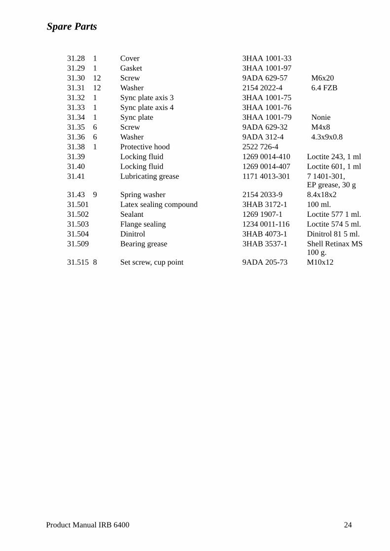
Spare Parts
31.28 1 Cover 3HAA 1001-3331.29 1 Gasket 3HAA 1001-9731.30 12 Screw 9ADA 629-57 M6x2031.31 12 Washer 2154 2022-4 6.4 FZB31.32 1 Sync plate axis 3 3HAA 1001-7531.33 1 Sync plate axis 4 3HAA 1001-7631.34 1 Sync plate 3HAA 1001-79 Nonie31.35 6 Screw 9ADA 629-32 M4x831.36 6 Washer 9ADA 312-4 4.3x9x0.831.38 1 Protective hood 2522 726-431.39 Locking fluid 1269 0014-410 Loctite 243, 1 ml31.40 Locking fluid 1269 0014-407 Loctite 601, 1 ml31.41 Lubricating grease 1171 4013-301 7 1401-301,
EP grease, 30 g31.43 9 Spring washer 2154 2033-9 8.4x18x231.501 Latex sealing compound 3HAB 3172-1 100 ml.31.502 Sealant 1269 1907-1 Loctite 577 1 ml.31.503 Flange sealing 1234 0011-116 Loctite 574 5 ml.31.504 Dinitrol 3HAB 4073-1 Dinitrol 81 5 ml.31.509 Bearing grease 3HAB 3537-1 Shell Retinax MS
100 g.31.515 8 Set screw, cup point 9ADA 205-73 M10x12
Product Manual IRB 6400 24
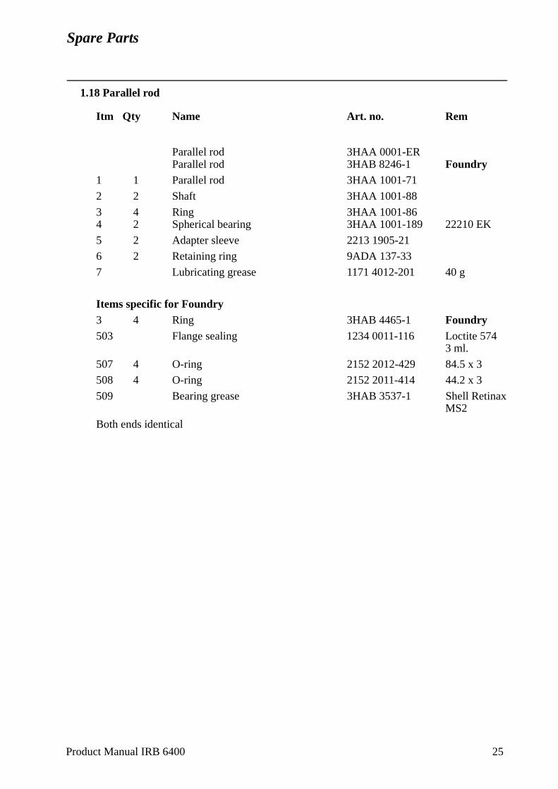
Spare Parts
1.18 Parallel rod
Itm Qty Name Art. no. Rem
Parallel rod 3HAA 0001-ERParallel rod 3HAB 8246-1 Foundry
1 1 Parallel rod 3HAA 1001-71
2 2 Shaft 3HAA 1001-88
3 4 Ring 3HAA 1001-864 2 Spherical bearing 3HAA 1001-189 22210 EK
5 2 Adapter sleeve 2213 1905-21
6 2 Retaining ring 9ADA 137-33
7 Lubricating grease 1171 4012-201 40 g
Items specific for Foundry3 4 Ring 3HAB 4465-1 Foundry503 Flange sealing 1234 0011-116 Loctite 574
3 ml.
507 4 O-ring 2152 2012-429 84.5 x 3
508 4 O-ring 2152 2011-414 44.2 x 3
509 Bearing grease 3HAB 3537-1 Shell Retinax MS2
Both ends identical
Product Manual IRB 6400 25
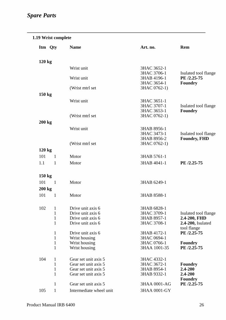
Spare Parts
1.19 Wrist complete
Itm Qty Name Art. no. Rem
120 kgWrist unit 3HAC 3652-1
3HAC 3706-1 Isulated tool flangeWrist unit 3HAB 4196-1 PE /2.25-75
3HAC 3654-1 Foundry(Wrist mtrl set 3HAC 0762-1)
150 kgWrist unit 3HAC 3651-1
3HAC 3707-1 Isulated tool flange3HAC 3653-1 Foundry
(Wrist mtrl set 3HAC 0762-1)
200 kgWrist unit 3HAB 8956-1
3HAC 3473-1 Isulated tool flange3HAB 8956-2 Foundry, FHD
(Wrist mtrl set 3HAC 0762-1)
120 kg101 1 Motor 3HAB 5761-1
1.1 1 Motor 3HAB 4041-1 PE /2.25-75
150 kg101 1 Motor 3HAB 6249-1
200 kg101 1 Motor 3HAB 8588-1
102 1 Drive unit axis 6 3HAB 6828-11 Drive unit axis 6 3HAC 3709-1 Isulated tool flange1 Drive unit axis 6 3HAB 8957-1 2.4-200, FHD1 Drive unit axis 6 3HAC 3708-1 2.4-200, Isulated
tool flange1 Drive unit axis 6 3HAB 4172-1 PE /2.25-751 Wrist housing 3HAC 0694-11 Wrist housing 3HAC 0766-1 Foundry1 Wrist housing 3HAA 1001-35 PE /2.25-75
104 1 Gear set unit axis 5 3HAC 4332-11 Gear set unit axis 5 3HAC 3672-1 Foundry1 Gear set unit axis 5 3HAB 8954-1 2.4-2001 Gear set unit axis 5 3HAB 9332-1 2.4-200
Foundry1 Gear set unit axis 5 3HAA 0001-AG PE /2.25-75
105 1 Intermediate wheel unit 3HAA 0001-GY
Product Manual IRB 6400 26
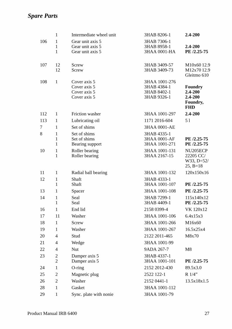
Spare Parts
1 Intermediate wheel unit 3HAB 8206-1 2.4-200106 1 Gear unit axis 5 3HAB 7306-1
1 Gear unit axis 5 3HAB 8958-1 2.4-2001 Gear unit axis 5 3HAA 0001-HA PE /2.25-75
107 12 Screw 3HAB 3409-57 M10x60 12.912 Screw 3HAB 3409-73 M12x70 12.9
Gleitmo 610
108 1 Cover axis 5 3HAA 1001-276Cover axis 5 3HAB 4384-1 FoundryCover axis 5 3HAB 8402-1 2.4-200Cover axis 5 3HAB 9326-1 2.4-200
Foundry,FHD
112 1 Friction washer 3HAA 1001-297 2.4-200113 1 Lubricating oil 1171 2016-604 5 l
7 1 Set of shims 3HAA 0001-AE
8 1 Set of shims 3HAB 4335-11 Set of shims 3HAA 0001-AF PE /2.25-751 Bearing support 3HAA 1001-271 PE /2.25-75
10 1 Roller bearing 3HAA 1001-131 NU205ECP1 Roller bearing 3HAA 2167-15 22205 CC/
W33, D=52/25, B=18
11 1 Radial ball bearing 3HAA 1001-132 120x150x16
12 1 Shaft 3HAB 4333-11 Shaft 3HAA 1001-107 PE /2.25-75
13 1 Spacer 3HAA 1001-108 PE /2.25-7514 1 Seal 3HAB 7299-1 115x140x12
1 Seal 3HAB 4409-1 PE /2.25-7516 1 End lid 2158 0399-4 VK 120x12
17 11 Washer 3HAA 1001-106 6.4x15x3
18 1 Screw 3HAA 1001-266 M16x60
19 1 Washer 3HAA 1001-267 16.5x25x4
20 4 Stud 2122 2011-465 M8x70
21 4 Wedge 3HAA 1001-99
22 4 Nut 9ADA 267-7 M8
23 2 Damper axis 5 3HAB 4337-12 Damper axis 5 3HAA 1001-101 PE /2.25-75
24 1 O-ring 2152 2012-430 89.5x3.0
25 2 Magnetic plug 2522 122-1 R 1/4”
26 2 Washer 2152 0441-1 13.5x18x1.5
28 1 Gasket 3HAA 1001-112
29 1 Sync. plate with nonie 3HAA 1001-79
Product Manual IRB 6400 27
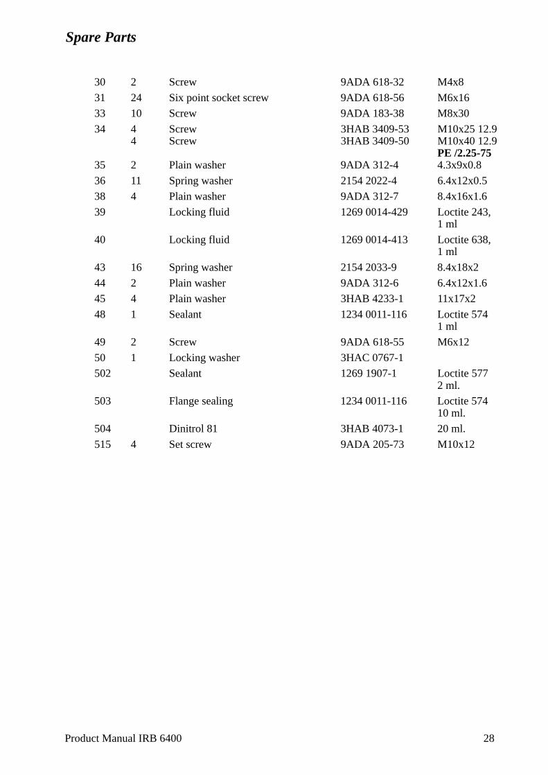
Spare Parts
30 2 Screw 9ADA 618-32 M4x8
31 24 Six point socket screw 9ADA 618-56 M6x16
33 10 Screw 9ADA 183-38 M8x30
34 4 Screw 3HAB 3409-53 M10x25 12.94 Screw 3HAB 3409-50 M10x40 12.9
PE /2.25-7535 2 Plain washer 9ADA 312-4 4.3x9x0.8
36 11 Spring washer 2154 2022-4 6.4x12x0.5
38 4 Plain washer 9ADA 312-7 8.4x16x1.6
39 Locking fluid 1269 0014-429 Loctite 243, 1 ml
40 Locking fluid 1269 0014-413 Loctite 638, 1 ml
43 16 Spring washer 2154 2033-9 8.4x18x2
44 2 Plain washer 9ADA 312-6 6.4x12x1.6
45 4 Plain washer 3HAB 4233-1 11x17x2
48 1 Sealant 1234 0011-116 Loctite 5741 ml
49 2 Screw 9ADA 618-55 M6x12
50 1 Locking washer 3HAC 0767-1
502 Sealant 1269 1907-1 Loctite 5772 ml.
503 Flange sealing 1234 0011-116 Loctite 57410 ml.
504 Dinitrol 81 3HAB 4073-1 20 ml.
515 4 Set screw 9ADA 205-73 M10x12
Product Manual IRB 6400 28
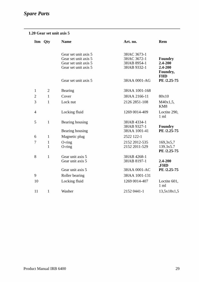
Spare Parts
1.20 Gear set unit axis 5
Itm Qty Name Art. no. Rem
Gear set unit axis 5 3HAC 3673-1Gear set unit axis 5 3HAC 3672-1 FoundryGear set unit axis 5 3HAB 8954-1 2.4-200Gear set unit axis 5 3HAB 9332-1 2.4-200
Foundry,FHD
Gear set unit axis 5 3HAA 0001-AG PE /2.25-75
1 2 Bearing 3HAA 1001-168
2 1 Cover 3HAA 2166-11 80x10
3 1 Lock nut 2126 2851-108 M40x1,5,KM8
4 Locking fluid 1269 0014-409 Loctite 290, 1 ml
5 1 Bearing housing 3HAB 4334-13HAB 9327-1 Foundry
Bearing housing 3HAA 1001-41 PE /2.25-756 1 Magnetic plug 2522 122-1
7 1 O-ring 2152 2012-535 169,3x5,71 O-ring 2152 2011-529 139.3x5.7
PE /2.25-758 1 Gear unit axis 5 3HAB 4268-1
Gear unit axis 5 3HAB 8197-1 2.4-200,FHD
Gear unit axis 5 3HAA 0001-AC PE /2.25-759 Roller bearing 3HAA 1001-131
10 Locking fluid 1269 0014-407 Loctite 601, 1 ml
11 1 Washer 2152 0441-1 13,5x18x1,5
Product Manual IRB 6400 29
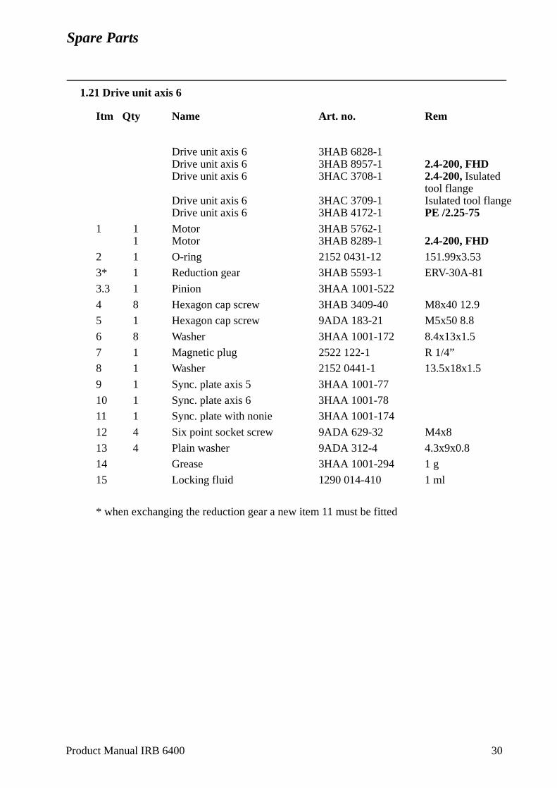
Spare Parts
1.21 Drive unit axis 6
Itm Qty Name Art. no. Rem
Drive unit axis 6 3HAB 6828-1Drive unit axis 6 3HAB 8957-1 2.4-200, FHDDrive unit axis 6 3HAC 3708-1 2.4-200, Isulated
tool flangeDrive unit axis 6 3HAC 3709-1 Isulated tool flangeDrive unit axis 6 3HAB 4172-1 PE /2.25-75
1 1 Motor 3HAB 5762-11 Motor 3HAB 8289-1 2.4-200, FHD
2 1 O-ring 2152 0431-12 151.99x3.53
3* 1 Reduction gear 3HAB 5593-1 ERV-30A-81
3.3 1 Pinion 3HAA 1001-522
4 8 Hexagon cap screw 3HAB 3409-40 M8x40 12.9
5 1 Hexagon cap screw 9ADA 183-21 M5x50 8.8
6 8 Washer 3HAA 1001-172 8.4x13x1.5
7 1 Magnetic plug 2522 122-1 R 1/4”
8 1 Washer 2152 0441-1 13.5x18x1.5
9 1 Sync. plate axis 5 3HAA 1001-77
10 1 Sync. plate axis 6 3HAA 1001-78
11 1 Sync. plate with nonie 3HAA 1001-174
12 4 Six point socket screw 9ADA 629-32 M4x8
13 4 Plain washer 9ADA 312-4 4.3x9x0.8
14 Grease 3HAA 1001-294 1 g
15 Locking fluid 1290 014-410 1 ml
* when exchanging the reduction gear a new item 11 must be fitted
Product Manual IRB 6400 30
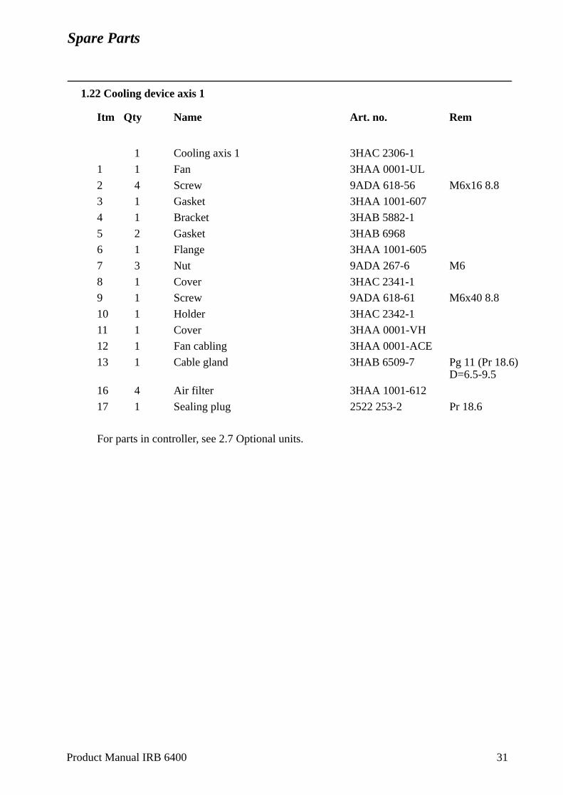
Spare Parts
1.22 Cooling device axis 1
Itm Qty Name Art. no. Rem
1 Cooling axis 1 3HAC 2306-1
1 1 Fan 3HAA 0001-UL
2 4 Screw 9ADA 618-56 M6x16 8.8
3 1 Gasket 3HAA 1001-607
4 1 Bracket 3HAB 5882-1
5 2 Gasket 3HAB 6968
6 1 Flange 3HAA 1001-605
7 3 Nut 9ADA 267-6 M6
8 1 Cover 3HAC 2341-1
9 1 Screw 9ADA 618-61 M6x40 8.8
10 1 Holder 3HAC 2342-1
11 1 Cover 3HAA 0001-VH
12 1 Fan cabling 3HAA 0001-ACE
13 1 Cable gland 3HAB 6509-7 Pg 11 (Pr 18.6)D=6.5-9.5
16 4 Air filter 3HAA 1001-612
17 1 Sealing plug 2522 253-2 Pr 18.6
For parts in controller, see 2.7 Optional units.
Product Manual IRB 6400 31
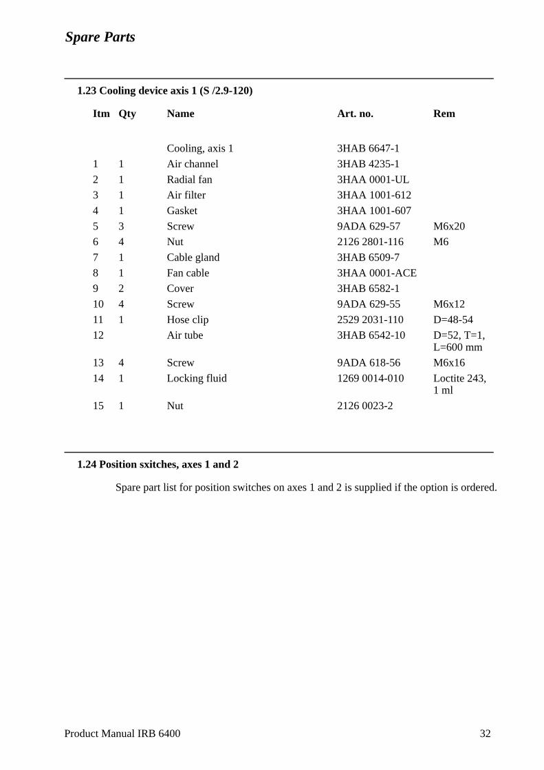
Spare Parts
1.23 Cooling device axis 1 (S /2.9-120)
Itm Qty Name Art. no. Rem
Cooling, axis 1 3HAB 6647-1
1 1 Air channel 3HAB 4235-1
2 1 Radial fan 3HAA 0001-UL
3 1 Air filter 3HAA 1001-612
4 1 Gasket 3HAA 1001-607
5 3 Screw 9ADA 629-57 M6x20
6 4 Nut 2126 2801-116 M6
7 1 Cable gland 3HAB 6509-7
8 1 Fan cable 3HAA 0001-ACE
9 2 Cover 3HAB 6582-1
10 4 Screw 9ADA 629-55 M6x12
11 1 Hose clip 2529 2031-110 D=48-54
12 Air tube 3HAB 6542-10 D=52, T=1, L=600 mm
13 4 Screw 9ADA 618-56 M6x16
14 1 Locking fluid 1269 0014-010 Loctite 243, 1 ml
15 1 Nut 2126 0023-2
1.24 Position sxitches, axes 1 and 2
Spare part list for position switches on axes 1 and 2 is supplied if the option is ordered.
Product Manual IRB 6400 32
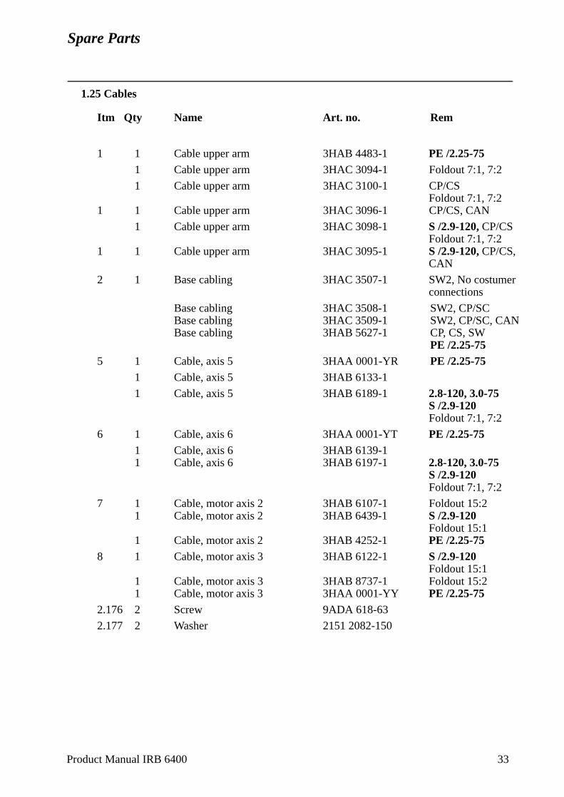
Spare Parts
1.25 Cables
Itm Qty Name Art. no. Rem
1 1 Cable upper arm 3HAB 4483-1 PE /2.25-751 Cable upper arm 3HAC 3094-1 Foldout 7:1, 7:2
1 Cable upper arm 3HAC 3100-1 CP/CSFoldout 7:1, 7:2
1 1 Cable upper arm 3HAC 3096-1 CP/CS, CAN
1 Cable upper arm 3HAC 3098-1 S /2.9-120, CP/CSFoldout 7:1, 7:2
1 1 Cable upper arm 3HAC 3095-1 S /2.9-120, CP/CS, CAN
2 1 Base cabling 3HAC 3507-1 SW2, No costumer connections
Base cabling 3HAC 3508-1 SW2, CP/SCBase cabling 3HAC 3509-1 SW2, CP/SC, CANBase cabling 3HAB 5627-1 CP, CS, SW
PE /2.25-755 1 Cable, axis 5 3HAA 0001-YR PE /2.25-75
1 Cable, axis 5 3HAB 6133-1
1 Cable, axis 5 3HAB 6189-1 2.8-120, 3.0-75S /2.9-120Foldout 7:1, 7:2
6 1 Cable, axis 6 3HAA 0001-YT PE /2.25-751 Cable, axis 6 3HAB 6139-11 Cable, axis 6 3HAB 6197-1 2.8-120, 3.0-75
S /2.9-120Foldout 7:1, 7:2
7 1 Cable, motor axis 2 3HAB 6107-1 Foldout 15:21 Cable, motor axis 2 3HAB 6439-1 S /2.9-120
Foldout 15:11 Cable, motor axis 2 3HAB 4252-1 PE /2.25-75
8 1 Cable, motor axis 3 3HAB 6122-1 S /2.9-120Foldout 15:1
1 Cable, motor axis 3 3HAB 8737-1 Foldout 15:21 Cable, motor axis 3 3HAA 0001-YY PE /2.25-75
2.176 2 Screw 9ADA 618-63
2.177 2 Washer 2151 2082-150
Product Manual IRB 6400 33
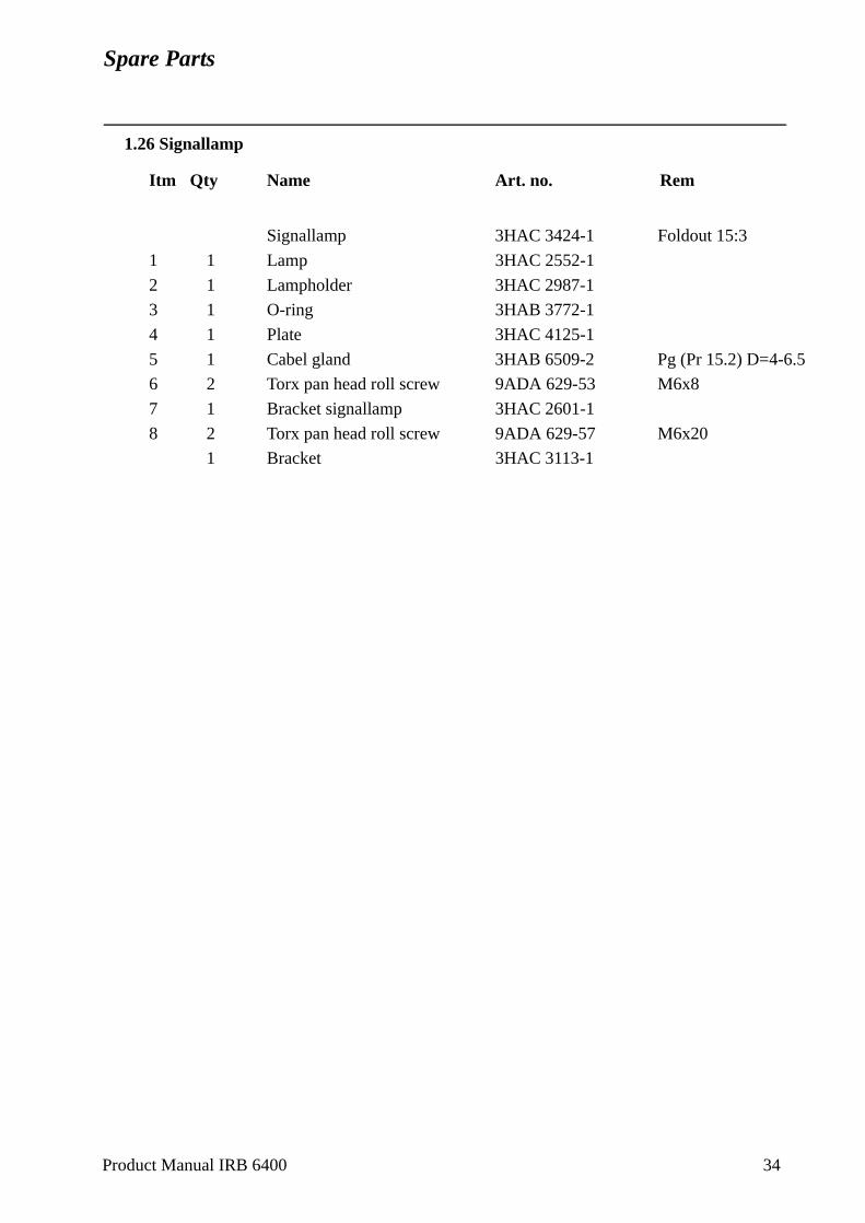
Spare Parts
1.26 Signallamp
Itm Qty Name Art. no. Rem
Signallamp 3HAC 3424-1 Foldout 15:3
1 1 Lamp 3HAC 2552-1
2 1 Lampholder 3HAC 2987-1
3 1 O-ring 3HAB 3772-1
4 1 Plate 3HAC 4125-1
5 1 Cabel gland 3HAB 6509-2 Pg (Pr 15.2) D=4-6.5
6 2 Torx pan head roll screw 9ADA 629-53 M6x8
7 1 Bracket signallamp 3HAC 2601-1
8 2 Torx pan head roll screw 9ADA 629-57 M6x20
1 Bracket 3HAC 3113-1
Product Manual IRB 6400 34
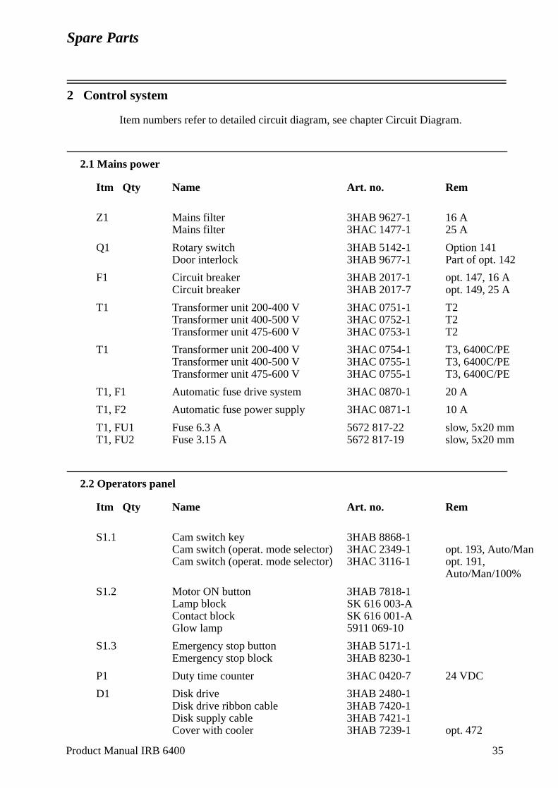
Spare Parts
Product Manual IRB 6400 35
2 Control system
Item numbers refer to detailed circuit diagram, see chapter Circuit Diagram.
2.1 Mains power
Itm Qty Name Art. no. Rem
Z1 Mains filter 3HAB 9627-1 16 AMains filter 3HAC 1477-1 25 A
Q1 Rotary switch 3HAB 5142-1 Option 141Door interlock 3HAB 9677-1 Part of opt. 142
F1 Circuit breaker 3HAB 2017-1 opt. 147, 16 ACircuit breaker 3HAB 2017-7 opt. 149, 25 A
T1 Transformer unit 200-400 V 3HAC 0751-1 T2Transformer unit 400-500 V 3HAC 0752-1 T2Transformer unit 475-600 V 3HAC 0753-1 T2
T1 Transformer unit 200-400 V 3HAC 0754-1 T3, 6400C/PETransformer unit 400-500 V 3HAC 0755-1 T3, 6400C/PETransformer unit 475-600 V 3HAC 0755-1 T3, 6400C/PE
T1, F1 Automatic fuse drive system 3HAC 0870-1 20 A
T1, F2 Automatic fuse power supply 3HAC 0871-1 10 A
T1, FU1 Fuse 6.3 A 5672 817-22 slow, 5x20 mmT1, FU2 Fuse 3.15 A 5672 817-19 slow, 5x20 mm
2.2 Operators panel
Itm Qty Name Art. no. Rem
S1.1 Cam switch key 3HAB 8868-1Cam switch (operat. mode selector) 3HAC 2349-1 opt. 193, Auto/ManCam switch (operat. mode selector) 3HAC 3116-1 opt. 191,
Auto/Man/100%
S1.2 Motor ON button 3HAB 7818-1Lamp block SK 616 003-AContact block SK 616 001-AGlow lamp 5911 069-10
S1.3 Emergency stop button 3HAB 5171-1Emergency stop block 3HAB 8230-1
P1 Duty time counter 3HAC 0420-7 24 VDC
D1 Disk drive 3HAB 2480-1Disk drive ribbon cable 3HAB 7420-1Disk supply cable 3HAB 7421-1Cover with cooler 3HAB 7239-1 opt. 472
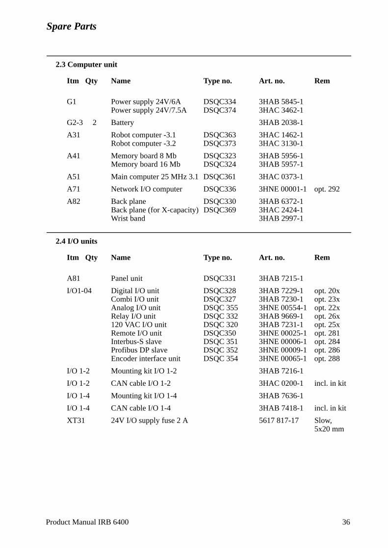
Spare Parts
2.3 Computer unit
Itm Qty Name Type no. Art. no. Rem
G1 Power supply 24V/6A DSQC334 3HAB 5845-1Power supply 24V/7.5A DSQC374 3HAC 3462-1
G2-3 2 Battery 3HAB 2038-1
A31 Robot computer -3.1 DSQC363 3HAC 1462-1Robot computer -3.2 DSQC373 3HAC 3130-1
A41 Memory board 8 Mb DSQC323 3HAB 5956-1Memory board 16 Mb DSQC324 3HAB 5957-1
A51 Main computer 25 MHz 3.1 DSQC361 3HAC 0373-1
A71 Network I/O computer DSQC336 3HNE 00001-1 opt. 292
A82 Back plane DSQC330 3HAB 6372-1Back plane (for X-capacity) DSQC369 3HAC 2424-1Wrist band 3HAB 2997-1
2.4 I/O units
Itm Qty Name Type no. Art. no. Rem
A81 Panel unit DSQC331 3HAB 7215-1
I/O1-04 Digital I/O unit DSQC328 3HAB 7229-1 opt. 20xCombi I/O unit DSQC327 3HAB 7230-1 opt. 23xAnalog I/O unit DSQC 355 3HNE 00554-1 opt. 22xRelay I/O unit DSQC 332 3HAB 9669-1 opt. 26x120 VAC I/O unit DSQC 320 3HAB 7231-1 opt. 25xRemote I/O unit DSQC350 3HNE 00025-1 opt. 281 Interbus-S slave DSQC 351 3HNE 00006-1 opt. 284Profibus DP slave DSQC 352 3HNE 00009-1 opt. 286Encoder interface unit DSQC 354 3HNE 00065-1 opt. 288
I/O 1-2 Mounting kit I/O 1-2 3HAB 7216-1
I/O 1-2 CAN cable I/O 1-2 3HAC 0200-1 incl. in kit
I/O 1-4 Mounting kit I/O 1-4 3HAB 7636-1
I/O 1-4 CAN cable I/O 1-4 3HAB 7418-1 incl. in kit
XT31 24V I/O supply fuse 2 A 5617 817-17 Slow, 5x20 mm
Product Manual IRB 6400 36
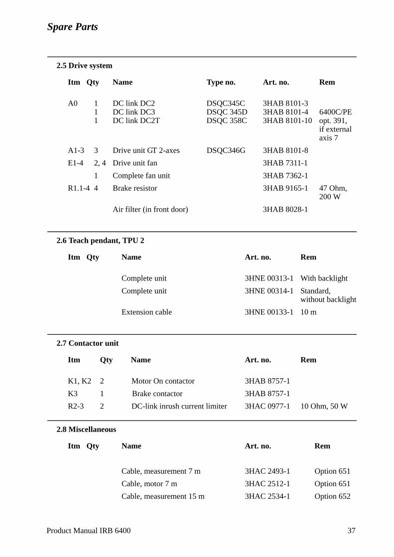
Spare Parts
2.5 Drive system
Itm Qty Name Type no. Art. no. Rem
A0 1 DC link DC2 DSQC345C 3HAB 8101-31 DC link DC3 DSQC 345D 3HAB 8101-4 6400C/PE1 DC link DC2T DSQC 358C 3HAB 8101-10 opt. 391,
if externalaxis 7
A1-3 3 Drive unit GT 2-axes DSQC346G 3HAB 8101-8
E1-4 2, 4 Drive unit fan 3HAB 7311-1
1 Complete fan unit 3HAB 7362-1
R1.1-4 4 Brake resistor 3HAB 9165-1 47 Ohm, 200 W
Air filter (in front door) 3HAB 8028-1
2.6 Teach pendant, TPU 2
Itm Qty Name Art. no. Rem
Complete unit 3HNE 00313-1 With backlight
Complete unit 3HNE 00314-1 Standard, without backlight
Extension cable 3HNE 00133-1 10 m
2.7 Contactor unit
Itm Qty Name Art. no. Rem
K1, K2 2 Motor On contactor 3HAB 8757-1
K3 1 Brake contactor 3HAB 8757-1
R2-3 2 DC-link inrush current limiter 3HAC 0977-1 10 Ohm, 50 W
2.8 Miscellaneous
Itm Qty Name Art. no. Rem
Cable, measurement 7 m 3HAC 2493-1 Option 651
Cable, motor 7 m 3HAC 2512-1 Option 651
Cable, measurement 15 m 3HAC 2534-1 Option 652
Product Manual IRB 6400 37
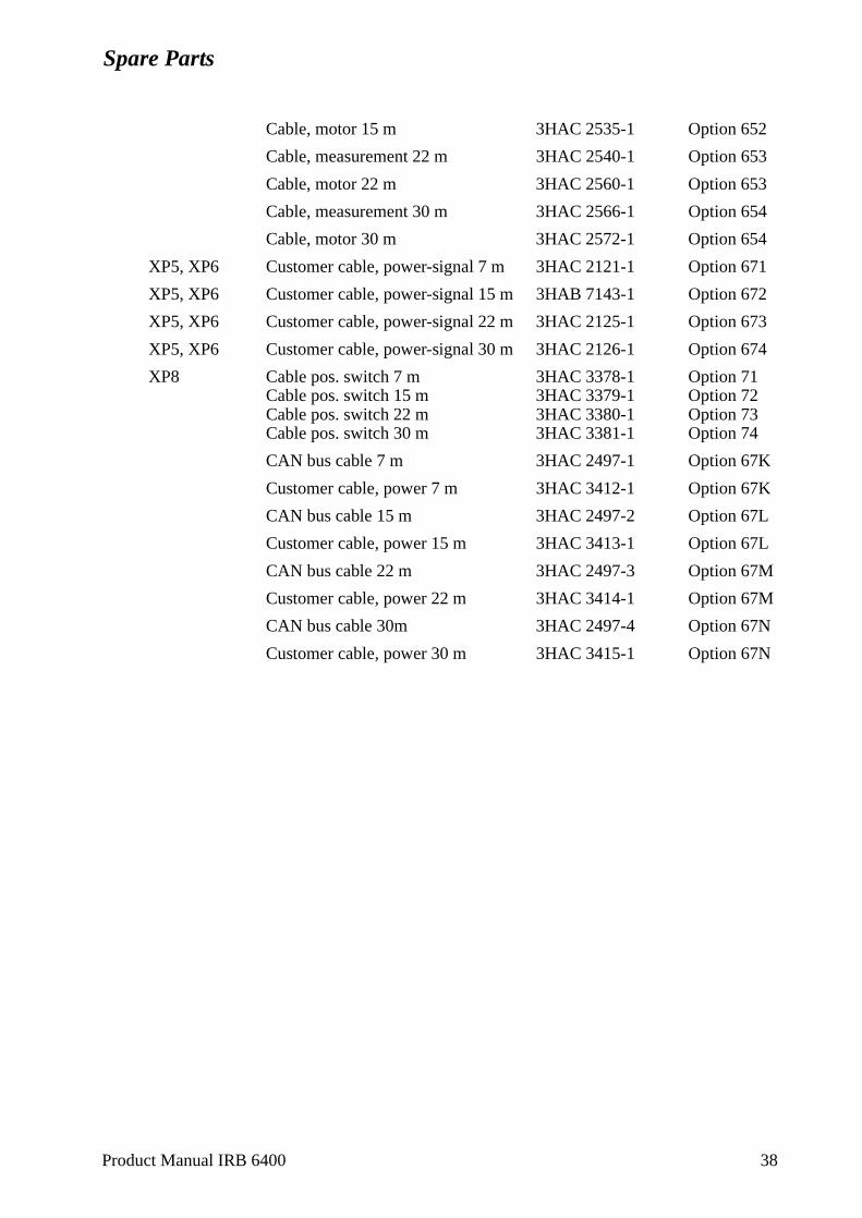
Spare Parts
Cable, motor 15 m 3HAC 2535-1 Option 652
Cable, measurement 22 m 3HAC 2540-1 Option 653
Cable, motor 22 m 3HAC 2560-1 Option 653
Cable, measurement 30 m 3HAC 2566-1 Option 654
Cable, motor 30 m 3HAC 2572-1 Option 654
XP5, XP6 Customer cable, power-signal 7 m 3HAC 2121-1 Option 671
XP5, XP6 Customer cable, power-signal 15 m 3HAB 7143-1 Option 672
XP5, XP6 Customer cable, power-signal 22 m 3HAC 2125-1 Option 673
XP5, XP6 Customer cable, power-signal 30 m 3HAC 2126-1 Option 674
XP8 Cable pos. switch 7 m 3HAC 3378-1 Option 71Cable pos. switch 15 m 3HAC 3379-1 Option 72Cable pos. switch 22 m 3HAC 3380-1 Option 73Cable pos. switch 30 m 3HAC 3381-1 Option 74
CAN bus cable 7 m 3HAC 2497-1 Option 67K
Customer cable, power 7 m 3HAC 3412-1 Option 67K
CAN bus cable 15 m 3HAC 2497-2 Option 67L
Customer cable, power 15 m 3HAC 3413-1 Option 67L
CAN bus cable 22 m 3HAC 2497-3 Option 67M
Customer cable, power 22 m 3HAC 3414-1 Option 67M
CAN bus cable 30m 3HAC 2497-4 Option 67N
Customer cable, power 30 m 3HAC 3415-1 Option 67N
Product Manual IRB 6400 38


![Owners Manual 9000 M98 [OCR]](https://img.pdfslide.us/doc/110x75/577cc38d1a28aba71196590a/owners-manual-9000-m98-ocr.jpg)