Embed Size (px)
Citation preview

CHAPTER 1
INTRODUCTION
1.1 Introduction of Water Chillers
A CHILLER is a device which cools a fluid by removing heat from it, either through a
VAPOUR COMPRESSION or ABSORPTION REFRIGERATION CYCLE with the key
components being the compressor, condenser, evaporator and expansion device. Most
typically, the fluid used in chillers is water, which can sometimes be treated with anti-
freeze to prevent it from freezing in low temperature applications. Once chilled, this water
is then used to cool and dehumidify air in a range of applications, from office buildings
and shopping centres, to laboratories and manufacturing facilities. The chiller takes the
heat from the water, at the evaporator, and in doing so lowers its temperature before
rejecting it through the condenser. This method of moving the heat from the chiller’s
evaporator to its condenser is refrigeration – which can be electric driven using
compressors or achieved through absorption which is achieved through a heat source such
as steam, hot water or another indirect source.
Fig 1.1: Water cooled –Water chiller
1

Water chillers are backbone of HVAC cooling systems. Water chiller is a refrigeration
machine which produces chilled water (Approximately 7 Degree C ~ 12 Degree C).The
primary function of a chiller is to lower the temperature of water to such value such that it
can be used for producing cooling effect in integration with other HVAC components.
A water chiller is just like a other refrigerator machine but instead of keeping the food cool
or making ice, it produces chilled water. The output of chiller is water at lower temperature
usually around about 10 o C depending upon the Chiller design.
HVAC water chillers play vital role in any HVAC systems along with other basic
components. Chillers have got much attention in recent years for its new designs and
performance improvement in existing designs. New designs have resulted in HVAC
chiller with better efficiency and less operation and maintenance costs. Another desirable
features is energy saving and precise load or capacity control for new chillers. The chillers
with above features are available in the market but as an engineering professionals, hope to
see more with design improvements with less operating and maintenance cost. It is
essential part of HVAC system to have a chiller. Chiller manufacturers have also expanded
their production as well design capabilities to cater to the diversified demands of HVAC
chillers.
HVAC (Heating, Ventilation, and Air Conditioning) is the technology of indoor and
vehicular environmental comfort. Its goal is to provide thermal comfort and
acceptable indoor air quality. HVAC system design is a sub discipline of mechanical
engineering, based on the principles of thermodynamics, fluid mechanics, and heat
transfer. Refrigeration is sometimes added to the field's abbreviation as HVAC&R or
HVACR, or ventilating is dropped as in HACR (such as the designation of HACR-rated
circuit breakers).
HVAC is important in the design of medium to large industrial and office buildings such
as skyscrapers and in marine environments such as aquariums, where safe and healthy
building conditions are regulated with respect to temperature and humidity, using fresh air
from outdoors.
Ventilating or Ventilation (the V in HVAC) is the process of "changing" or replacing air in
any space to provide high indoor air quality which involves temperature control, oxygen
replenishment, and removal of moisture, odours, smoke, heat, dust, airborne bacteria, and
2

carbon dioxide. Ventilation removes unpleasant smells and excessive moisture, introduces
outside air, keeps interior building air circulating, and prevents stagnation of the interior
air.
Ventilation includes both the exchange of air to the outside as well as circulation of air
within the building. It is one of the most important factors for maintaining acceptable
indoor air quality in buildings. Methods for ventilating a building may be divided
into mechanical/forced and natural types.
1.2 Classification of Water Chillers
1.2.1 Need For Classification :
Chiller Types have been designed to cater to the diversified requirement of industrial
chillers. Water chillers have evolved due to the variety in availability of type of energy at
industry or small level. Types of chillers have made the use of the chillers flexible in terms
of energy input.
Industrial research in the field of chiller has eased the selection of chillers in an economical
and robust manner. There is no need of worry whatever type of energy you have available
with you. Each type of chiller targets the specific users classified on the basis of type of
energy they have. HVAC systems employ different types of chillers within the available
resources of clients or users.
A chiller may be the best option for particular application while the same chiller may
costly or less feasible for another application or plant.
Water chillers are classified primarily on the basis of cycle on which they work:
Vapour compression chillers or compression chillers or electric chillers
Vapour absorption chillers or absorption chillers or ammonia chillers or lithium
bromide chillers
Vapour compression chillers are further classified on following basis.
1. Type of compressor
o reciprocating compressor type
o rotory compressor type
o screw compressor type
3

o Scroll compressor type
2. Type of condenser
o air cooled condenser or air cooled chillers
o water cooled condensers or water cooled chillers
While Vapour absorption chillers are further classified as following:
1. Direct fired absorption chillers (Natural gas, Diesel or Kerosene Oil Operated)
2. Indirect fired absorption chillers
Fig 1.2: Classification of Chillers
4

1.3 Types of Refrigeration Systems
1. Vapour compression refrigeration system.
2. Water refrigeration system.
3. Vortex and pulse tube refrigeration systems.
4. Vapour –Absorption system.
5. Thermoelectric refrigeration systems.
1.3.1 Vapour compression refrigeration system:
The challenge in refrigeration and air conditioning is to remove heat from a low
temperature source and dump it at a higher temperature sink. Compression refrigeration
cycles in general take advantage of the idea that highly compressed fluids at one
temperature will tend to get colder when they are allowed to expand. If the pressure change
is high enough, then the compressed gas will be hotter than our source of cooling (outside
air, for instance) and the expanded gas will be cooler than our desired cold temperature. In
this case, we can use it to cool at a low temperature and reject the heat to a high
temperature. Vapour-compression refrigeration cycles specifically have two additional
advantages. First, they exploit the large thermal energy required to change a liquid to a
vapour so we can remove lots of heat out of our air-conditioned space. Second, the
isothermal nature of the vaporization allows extraction of heat without raising the
temperature of the working fluid to the temperature of whatever is being cooled. This is a
benefit because the closer the working fluid temperature approaches that of the
surroundings, the lower the rate of heat transfer. The isothermal process allows the fastest
rate of heat transfer Vapour compression refrigeration is the primary method to provide
mechanical cooling.
All vapour compression systems consist of the following four basic components along
with the interconnecting piping. These are the evaporator, condenser, compressor and the
expansion valve. Typical vapour compression systems can be represented as shown in
figure.
5

Fig 1.3: Vapour Compression Refrigeration Cycle
Vapour Compression Refrigeration cycle:
Heat flows naturally from a hot to a colder body. In refrigeration system the opposite must
occur i.e. heat flows from a cold to a hotter body. This is achieved by using a substance
called a refrigerant, which absorbs heat and hence boils or evaporates at a low pressure to
form a gas. This gas is then compressed to a higher pressure, such that it transfers the heat
it has gained to ambient air or water and turns back (condenses) into a liquid. In this way
heat is absorbed, or removed, from a low temperature source and transferred to a higher
temperature source.
The refrigeration cycle can be broken down into the following stages.
1 – 2 Low pressure liquid refrigerant in the evaporator absorbs heat from its surroundings,
Usually air, water or some other process liquid. During this process it changes its state
from a liquid to a gas, and at the evaporator exit is slightly superheated.
2 – 3 the superheated vapour enters the compressor where its pressure is raised. There will
Also be a big increase in temperature, because a proportion of the energy input into the
compression process is transferred to the refrigerant.
6
3 – 4 the high pressure superheated gas passes from the compressor into the condenser.
The initial part of the cooling process (3 - 3a) DE superheats the gas before it is then turned
back into liquid (3a - 3b). The cooling for this process is usually achieved by using air or
water. A further reduction in temperature happens in the pipe work and liquid receiver (3b
- 4), so that the refrigerant liquid is sub-cooled as it enters the expansion device.
4 – 1 the high-pressure sub-cooled liquid passes through the expansion device, which both
Reduces its pressure and controls the flow into the evaporator.
Fig 1.4: Schematic of a Basic Vapour Compression Refrigeration System
It can be seen that the condenser has to be capable of rejecting the combined heat inputs of
the evaporator and the compressor; i.e. (1 – 2) + (2 – 3) has to be the same as (3 – 4). There
is no heat loss or gain through the expansion device.
1.3.2 Alternative Refrigerants for Vapour Compression Systems
The use of CFCs is now beginning to be phased out due to their damaging impact on the
protective tropospheric ozone layer around the earth. The Montreal Protocol of 1987 and
the subsequent Copenhagen agreement of 1992 mandate a reduction in the production of
ozone depleting Chlorinated Fluorocarbon (CFC) refrigerants in a phased manner, with an
eventual stop to all production by the year 1996. In response, the refrigeration industry has
7

developed two alternative refrigerants; one based on Hydrochloro Fluorocarbon (HCFC),
and another based on Hydro Fluorocarbon (HFC). The HCFCs have a 2 to 10% ozone
depleting potential as compared to CFCs and also, they have an atmospheric lifetime
between 2 to 25years as compared to 100 or more years for CFCs (Brandt, 1992). However, even
HCFCs are mandated to be phased out by 2005, and only the chlorine free (zero ozone
depletion)HFCs would be acceptable. Until now, only one HFC based refrigerant, HFC
134a, has been developed. HCFCs are comparatively simpler to produce and the three
refrigerants 22, 123, and 124 have been developed. The use of HFCs and HCFCs results in
slightly lower efficiencies as compared to CFCs, but this may change with increasing
efforts being made to replace CFCs.
8

CHAPTER 2
REFRIGERANTS
2.1 Introduction of Refrigerants
The thermodynamic efficiency of a refrigeration system depends mainly on its operating
temperatures. However, important practical issues such as the system design, size, initial
and operating costs, safety, reliability, and serviceability etc. depend very much on the type
of refrigerant selected for a given application. Due to several environmental issues such as
ozone layer depletion and global warming and their relation to the various refrigerants
used, the selection of suitable refrigerant has become one of the most important issues in
recent times. Replacement of an existing refrigerant by a completely new refrigerant, for
whatever reason, is an expensive proposition as it may call for several changes in the
design and manufacturing of refrigeration systems. Hence it is very important to
understand the issues related to the selection and use of refrigerants. In principle, any fluid
can be used as a refrigerant. Air used in an air cycle refrigeration system can also be
considered as a refrigerant.
Working Principle :
Under this heading, we have the primary or common refrigerants and the secondary
refrigerants.
The primary refrigerants are those that pass through the processes of compression, cooling
or condensation, expansion and evaporation or warming up during cyclic processes.
Ammonia, R12, R22, carbon dioxide come under this class of refrigerants.
On the other hand, the medium which does not go through the cyclic processes in a
refrigeration system and is only used as a medium for heat transfer are referred to as
secondary refrigerants. Water, brine solutions of sodium chloride and calcium chloride
come under this category.
2.2 Classification of refrigerants:
Refrigerants can be broadly classified based on the following:
9

2.2.1 Safety Considerations
Under this heading, we have the following three sub-divisions.
Safe refrigerants
These are the non-toxic, non-flammable refrigerants such as R11, R12, R13, R14, R21,
R22, R113, R114, methyl chloride, carbon dioxide, water etc.
Toxic and moderately flammable
Dichloroethylene methyl format, ethylchloride, sulphur dioxide, ammonia etc. come under
this category.
Highly flammable refrigerants
The refrigerants under this category are butane, isobutene, propane, ethane, methane,
ethylene etc.
2.2.2 Chemical Compositions
They are further sub-divided as
Halocarbon compounds
These are obtained by replacing one or more hydrogen atoms in ethane or methane with
halogens.
Azeotropes
These are the mixtures of two or more refrigerants and behave as a compound.
Oxygen and Nitrogen Compounds
Refrigerants having either oxygen or nitrogen molecules in their structure, such as
ammonia, are grouped separately and have a separate nomenclature from the halogenated
refrigerants.
Cyclic organic Compounds
The compounds coming under this class are R316, R317 and R318.
Inorganic Compounds
These are further divided into two categories: Cryogenic and Non-cryogenic.
Cryogenic fluids are those which are applied for achieving temperatures as low as – 160
0C to – 273 0C. Above this temperature range, we can use a multi-stage refrigeration
system to realise the desired temperature. But below – 160 0C, this is not possible since the
COP of the cycle becomes very low. To attain temperatures below – 160 0C, we use
10

refrigerants such as nitrogen, oxygen, helium, hydrogen etc. and for temperatures close to
– 273 0C, magnetic cooling is employed.
The inorganic compounds which are employed above the cryogenic temperature ranges
come under the remaining sub-division of inorganic refrigerants.
Unsaturated Compounds
Compounds such as ethylene, propylene etc. are grouped under this head and grouped
under the 1000 series for convenience.
Miscellaneous
This group contains those compounds which cannot be grouped under the other
components. They are indicated by the 700 series with the last numbers being their
molecular weight. Examples include air, carbon dioxide, sulphur dioxide etc.
As we can see from the above sub-divisions, they are not mutually exclusive. A compound
may come under more than one sub-division. Hence, the importance of adopting the
various naming conventions to designate the different refrigerants cannot be
underestimated.
2.3 Refrigerant selection criteria:
Selection of refrigerant for a particular application is based on the following requirements:
i. Thermodynamic and thermo-physical properties
ii. Environmental and safety properties, and
iii. Economics
2.3.1 Thermodynamic and thermo-physical properties:
The requirements are:
a) Suction pressure: At a given evaporator temperature, the saturation pressure should be
above atmospheric for prevention of air or moisture ingress into the system and ease of
leak detection. Higher suction pressure is better as it leads to smaller compressor
displacement
b) Discharge pressure:At a given condenser temperature, the discharge pressure should
be as small as possible to allow light-weight construction of compressor, condenser etc.
c) Pressure ratio:Should be as small as possible for high volumetric efficiency and low
power consumption
11

d) Latent heat of vaporization:Should be as large as possible so that the required mass
flow rate per unit cooling capacity will be small
e) Isentropic index of compression:Should be as small as possible so that the temperature
rise during compression will be small
f) Liquid specific heat:Should be small so that degree of subcooling will be large leading
to smaller amount of flash gas at evaporator inlet
g) Vapour specific heat:Should be large so that the degree of superheating will be small
h) Thermal conductivity: Thermal conductivity in both liquid as well as vapour phase
should be high for higher heat transfer coefficients
i) Viscosity: Viscosity should be small in both liquid and vapour phases for smaller
frictional pressure drops
The thermodynamic properties are interrelated and mainly depend on normal boiling point,
critical temperature, molecular weight and structure.
The normal boiling point indicates the useful temperature levels as it is directly
related to the operating pressures. A high critical temperature yields higher COP due to
smaller compressor superheat and smaller flash gas losses. On the other hand since the
vapour pressure will be low when critical temperature is high, the volumetric capacity will
be lower for refrigerants with high critical temperatures. This once again shows a need for
trade-off between high COP and high volumetric capacity. It is observed that for most of
the refrigerants the ratio of normal boiling point to critical temperature is in the range of
0.6 to 0.7. Thus the normal boiling point is a good indicator of the critical temperature of
the refrigerant.
The important properties such as latent heat of vaporization and specific heat
depend on the molecular weight and structure of the molecule. Trouton’s rule shows that
the latent heat of vaporization will be high for refrigerants having lower molecular weight.
The specific heat of refrigerant is related to the structure of the molecule. If specific heat of
refrigerant vapour is low then the shape of the vapour dome will be such that the
compression process starting with a saturated point terminates in the superheated zone (i.e,
compression process will be dry). However, a small value of vapour specific heat indicates
higher degree of superheat. Since vapour and liquid specific heats are also related, a large
value of vapour specific heat results in a higher value of liquid specific heat, leading to
higher flash gas losses. Studies show that in general the optimum value of molar vapour
specific heat lies in the range of 40 to 100 kJ/kmol.K.
12

The freezing point of the refrigerant should be lower than the lowest operating
temperature of the cycle to prevent blockage of refrigerant pipelines
2.3.2 Environmental and safety properties:
Next to thermodynamic and thermo physical properties, the environmental and safety
properties are very important. In fact, at present the environment friendliness of the
refrigerant is a major factor in deciding the usefulness of a particular refrigerant. The
important environmental and safety properties are:
a) Ozone Depletion Potential (ODP): According to the Montreal protocol, the ODP of
refrigerants should be zero, i.e., they should be non-ozone depleting substances.
Refrigerants having non-zero ODP have either already been phased-out (e.g. R 11, R 12)
or will be phased-out in near-future(e.g. R22). Since ODP depends mainly on the presence
of chlorine or bromine in the molecules, refrigerants having either chlorine (i.e., CFCs and
HCFCs) or bromine cannot be used under the new regulations
b) Global Warming Potential (GWP): Refrigerants should have as low a GWP value as
possible to minimize the problem of global warming. Refrigerants with zero ODP but a
high value of GWP (e.g. R134a) are likely to be regulated in future.
c) Total Equivalent Warming Index (TEWI): The factor TEWI considers both direct
(due to release into atmosphere) and indirect (through energy consumption) contributions
of refrigerants to global warming. Naturally, refrigerants with as a low a value of TEWI
are preferable from global warming point of view.
d) Toxicity: Ideally, refrigerants used in a refrigeration system should be non-toxic.
However, all fluids other than air can be called as toxic as they will cause suffocation when
their concentration is large enough. Thus toxicity is a relative term, which becomes
meaningful only when the degree of concentration and time of exposure required to
produce harmful effects are specified. Some fluids are toxic even in small concentrations.
Some fluids are mildly toxic, i.e., they are dangerous only when the concentration is large
and duration of exposure is long. Some refrigerants such as CFCs and HCFCs are non-
toxic when mixed with air in normal condition. However, when they come in contact with
an open flame or an electrical heating element, they decompose forming highly toxic
elements (e.g. phosgene-COCl2). In general the degree of hazard depends on:
- Amount of refrigerant used vs total space
- Type of occupancy
13

- Presence of open flames
- Odour of refrigerant, and
- Maintenance condition
Thus from toxicity point-of-view, the usefulness of a particular refrigerant depends on the
specific application.
e) Flammability: The refrigerants should preferably be non-flammable and non-explosive.
For flammable refrigerants special precautions should be taken to avoid accidents.
Based on the above criteria, ASHRAE has divided refrigerants into six safety groups
(A1 to A3 and B1 to B3). Refrigerants belonging to Group A1 (e.g. R11, R12, R22, R134a,
R744, R718) are least hazardous, while refrigerants belonging to Group B3 (e.g. R1140)
are most hazardous.
Other important properties are:
f) Chemical stability: The refrigerants should be chemically stable as long as they are
inside the refrigeration system.
g) Compatibility with common materials of construction (both metals and non-metals)
h) Miscibility with lubricating oils: Oil separators have to be used if the refrigerant is not
miscible with lubricating oil (e.g. ammonia). Refrigerants that are completely miscible
with oils are easier to handle (e.g. R12). However, for refrigerants with limited solubility
(e.g. R 22) special precautions should be taken while designing the system to ensure oil
return to the compressor
i) Dielectric strength: This is an important property for systems using hermetic
compressors. For these systems the refrigerants should have as high a dielectric strength as
possible
j) Ease of leak detection: In the event of leakage of refrigerant from the system, it should
be easy to detect the leaks.
2.3.3 Economic properties:
The refrigerant used should preferably be inexpensive and easily available.
14

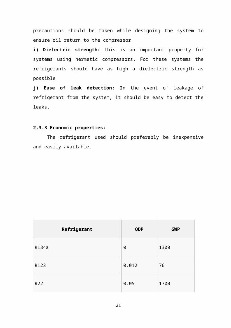
Refrigerant ODP GWP
R134a 0 1300
R123 0.012 76
R22 0.05 1700
R290 (propane) 0 3
R401a 0.027 970
R404a 0 3260
R407a 0 ??
R407c 0 1525
R408a 0.016 3020
R409a 0.039 1290
R410a 0 1725
R500 0.7 ???
R502 0.18 5600
15

R600a 0 3
R744 (CO2) 0 1
R717 (ammonia) 0 0
R718 (water) 0 0
Table: 2.1 Refrigerants ODP and GWP values
2.4 Comparison between different refrigerants:
Synthetic refrigerants that were commonly used for refrigeration, cold storage and air
conditioning applications are: R 11 (CFC 11), R 12 (CFC 12), R 22 (HCFC 22), R 502
(CFC 12+HCFC 22) etc. However, these refrigerants have to be phased out due to their
Ozone Depletion Potential (ODP). The synthetic replacements for the older refrigerants
are: R-134a (HFC-134a) and blends of HFCs. Generally, synthetic refrigerants are non-
toxic and non-flammable. However, compared to the natural refrigerants the synthetic
refrigerants offer lower performance and they also have higher Global Warming Potential
(GWP). As a result, the synthetic refrigerants face an uncertain future. The most commonly
used natural refrigerant is ammonia. This is also one of the oldest known refrigerants.
Ammonia has good thermodynamic, thermo physical and environmental properties.
However, it is toxic and is not compatible with some of the common materials of
construction such as copper, which somewhat restricts its application. Other natural
refrigerants that are being suggested are hydrocarbons (HCs) and carbon di-oxide (R-744).
Though these refrigerants have some specific problems owing to their eco-friendliness,
they are being studied widely and are likely to play a prominent role in future.
Prior to the environmental issues of ozone layer depletion and global warming, the most
widely used refrigerants were: R 11, R 12, R 22, R 502 and ammonia. Of these, R 11 was
primarily used with centrifugal compressors in air conditioning applications. R 12 was
used primarily in small capacity refrigeration and cold storage applications, while the other
refrigerants were used in large systems such as large air conditioning plants or cold
16

storages. Among the refrigerants used, except ammonia, all the other refrigerants are
synthetic refrigerants and are non-toxic and non-flammable. Though ammonia is toxic, it
has been very widely used due to its excellent thermodynamic and thermo physical
properties. The scenario changed completely after the discovery of ozone layer depletion in
1974. The depletion of stratospheric ozone layer was attributed to chlorine and bromine
containing chemicals such as Halons, CFCs, HCFCs etc. Since ozone layer depletion could
lead to catastrophe on a global level, it has been agreed by the global community to phase
out the ozone depleting substances (ODS). As a result except ammonia, all the other
refrigerants used in cold storages had to be phased-out and a search for suitable
replacements began in earnest. At the same time, it was also observed that in addition to
ozone layer depletion, most of the conventional synthetic refrigerants also cause significant
global warming. In view of the environmental problems caused by the synthetic
refrigerants, opinions differed on replacements for conventional refrigerants. The alternate
refrigerants can be classified into two broad groups
i) Non-ODS, synthetic refrigerants based on Hydro-Fluoro-Carbons (HFCs) and their
blends
ii) Natural refrigerants including ammonia, carbon dioxide, hydrocarbons and their
blends
It should be noted that the use of natural refrigerants such as carbon dioxide, hydrocarbons
is not a new phenomenon, but is a revival of the once-used-and-discarded technologies in a
much better form. Since the natural refrigerants are essentially making a comeback, one
advantage of using them is that they are familiar in terms of their strengths and
weaknesses. Another important advantage is that they are completely environment
friendly, unlike the HFC based refrigerants, which do have considerable global warming
potential. The alternate synthetic refrigerants are normally non-toxic and non-flammable. It
is also possible to use blends of various HFCs to obtain new refrigerant mixtures with
required properties to suit specific applications. However, most of these blends are non-
azeotropic in nature, as a result there could be significant temperature glides during
evaporation and condensation, and it is also important take precautions to prevent leakage,
as this will change the composition of the mixture.
CHAPTER 3
COMPONENTS OF REFRIGERATION SYSTEM
17

3.1 Compressor
The compressors are one of the most important parts of the refrigeration cycle. The
compressor compresses the refrigerant, which flows to the condenser, where it gets cooled.
It then moves to the expansion valve, and the evaporator and it is finally sucked by the
compressor again. For the proper functioning of the refrigeration cycle, the refrigerant
must be compressed to the pressure corresponding to the saturation temperature higher
than the temperature of the naturally available air or water. It is the crucial function that is
performed by the compressor. Compression of the refrigerant to the suitable pressure
ensures its proper condensation and circulation throughout the cycle. The capacity of the
refrigeration or air conditioning depends entirely on the capacity of the compressor.
Refrigeration compressors and air conditioning compressors provide air conditioning, heat
pumping, and refrigeration for large-scale facilities and equipment. They use compression
to raise the temperature of a low-pressure gas, and also remove vapour from the
evaporator. Most refrigeration compressors (refrigerant compressors) are large, mechanical
units that form the heart of industrial cooling, heating, ventilation, and air conditioning
(HVAC) systems.
Refrigerant compressors work by taking in low pressure gas on the inlet and compressing
it mechanically. This compression creates a high temperature, high pressure gas - an
essential step in the overarching refrigeration cycle.
3.1.1 Types of Compressors
There are a number of different types of compressors used for refrigeration and air
conditioning. Like pumps, all "heat pumps" can first be categorized as either positive
displacement or non-positive displacement (centrifugal). Positive displacement
compressors have chambers which decrease in volume during compression, while non-
positive displacement compressors have fixed-volume chambers. Beyond this
distinction, each type differs based on its specific mechanism for fluid compression. The
five main types of compressors are piston, rotary, screw, scroll, and centrifugal.
1. Piston Compressors
Piston compressors, also called reciprocating compressors, use a piston and cylinder
arrangement to provide compressive force - like combustion engines or piston pumps. The
18
reciprocating motion of the piston due to external power compresses the refrigerant inside
the cylinder. Piston compressors have a low initial cost and a simple, easy to install design.
They have a large power output range and can reach extremely high pressures. However,
they have high maintenance costs, potential vibrational issues, and are not typically
designed to run continuously at full capacity.
Fig 3.1: Piston compressor diagram.
2. Rotary Compressors
Rotary compressors have two rotating elements, like gears, between which the refrigerant
is compressed. These compressors are very efficient because the actions of taking in
refrigerant and compressing refrigerant occur simultaneously. They have very few moving
parts, low rotational speeds, low initial and maintenance costs, and are forgiving in dirty
environments. However, they are limited to smaller volumes of the gas and produce less
pressure than other types of compressors.
19
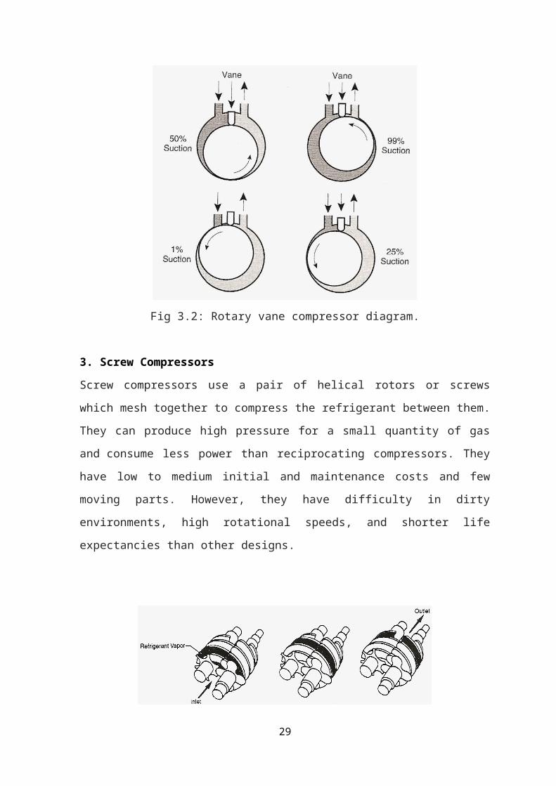
Fig 3.2: Rotary vane compressor diagram.
3. Screw Compressors
Screw compressors use a pair of helical rotors or screws which mesh together to compress
the refrigerant between them. They can produce high pressure for a small quantity of gas
and consume less power than reciprocating compressors. They have low to medium initial
and maintenance costs and few moving parts. However, they have difficulty in dirty
environments, high rotational speeds, and shorter life expectancies than other designs.
Fig 3.3: Screw compressor diagram
20
4. Scroll Compressors
Scroll compressors use two offset spiral disks nested together to compress the refrigerant.
The upper disk is stationary while the lower disk moves in orbital fashion. Scroll
compressors are quiet, smooth-operating units with few moving parts and the highest
efficiency ratio of all compressor types. They also are more flexible for
handling refrigerants in the liquid. However, as fully hermetic designs, scroll compressors
cannot be easily repaired. They also typically cannot rotate in both directions. Scroll
compressors are commonly used in automobile air conditioning systems and commercial
chillers.
Fig 3.4: Scroll compressor diagram.
5. Centrifugal Compressors
Centrifugal compressors use the rotating action of an impeller wheel to exert centrifugal
force on refrigerant inside a round chamber (volute). Unlike other designs, centrifugal
compressors do not operate on the positive displacement principle, but have fixed volume
chambers. They are well suited to compressing large volumes of refrigerant to relatively
low pressures. The compressive force generated by an impeller wheel is small, so systems
that use centrifugal compressors usually employ two or more stages (impellers wheels) in
21

series to generate high compressive forces. Centrifugal compressors are desirable for their
simple design, few moving parts, and energy efficiency when operating multiple stages.
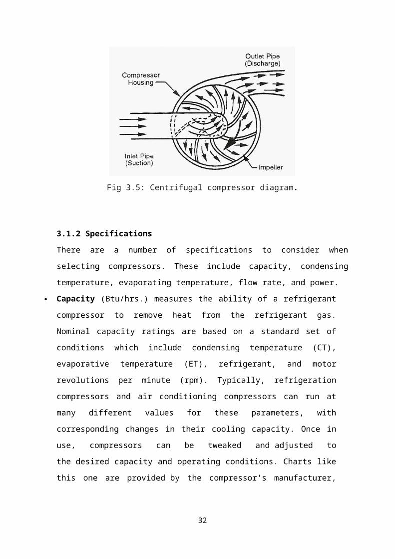
Fig 3.5: Centrifugal compressor diagram.
3.1.2 Specifications
There are a number of specifications to consider when selecting compressors. These
include capacity, condensing temperature, evaporating temperature, flow rate, and power.
Capacity (Btu/hrs.) measures the ability of a refrigerant compressor to remove heat
from the refrigerant gas. Nominal capacity ratings are based on a standard set of
conditions which include condensing temperature (CT), evaporative temperature (ET),
refrigerant, and motor revolutions per minute (rpm). Typically, refrigeration
compressors and air conditioning compressors can run at many different values for
these parameters, with corresponding changes in their cooling capacity. Once in use,
compressors can be tweaked and adjusted to the desired capacity and operating
conditions. Charts like this one are provided by the compressor's manufacturer,
allowing engineers to make these adjustments properly once in the system:
Condensing temperature is the range of condensing temperatures over which the
compressor is rated to operate.
Evaporating temperature is the range of evaporative temperatures over which the
compressor is rated to operate.
22

Flow rate is the rate (by mass) at which he fluid is passed through the compressor,
measured in pounds per hour (lb./hr.) or kilograms per hour (kg/hr.).
Power (W) is the input power required to run the compressor motor at a specific
operating point.
Refrigeration compressors and air conditioning compressors also carry power-source
specifications defined by voltage / frequency / phase. Common choices include 12 VDC
and 24 VDC, as well as 115/60/1, 230/50/1, 208-230/60/1, 208-230/60/3, 380/50/3,
460/60/3 and 575/60/3.
3.2 Condenser
In systems involving heat transfer, a condenser is a device or unit used to condense a
substance from its gaseous to its liquid state, typically by cooling it. In so doing, the latent
heat is given up by the substance, and will transfer to the condenser coolant. Condensers
are typically heat exchangers which have various designs and come in many sizes ranging
from rather small (hand-held) to very large industrial-scale units used in plant processes.
For example, a refrigerator uses a condenser to get rid of heat extracted from the interior of
the unit to the outside air. Condensers are used in air conditioning, industrial chemical
processes such as distillation, steam power plants and other heat-exchange systems. Use of
cooling water or surrounding air as the coolant is common in many condensers.
3.2.1 Types of Condenser:
There are three types of condensers, viz.
(a) Air- cooled,
(b) Water-cooled and
(c) Evaporative.
As their names imply, air-cooled condensers use air as the cooling medium, water-cooled
condensers use water as the medium and the evaporative condenser is a combination of the
above, i.e. uses both water and air.
a) Air-Cooled Condensers
There are two types under this category, viz. (i) natural convection and (ii) forced-air type.
23

i) Natural Convection Condenser
Air movement over the surface of condenser tubes is by natural convection. As air comes
in contact with the warm-condenser tubes, it absorbs heat from the refrigerant and thus the
temperature of the air increases. Warm air being lighter, rises up and in its place cooler air
from below rises to take away the heat from the condenser. This cycle goes on. Since air
moves very slowly by natural convection, the rate of flow of heat from the refrigerant to air
will be small. Thus a natural convection condenser is not capable of rejecting heat rapidly.
Therefore a relatively large surface area of the condenser is required. Hence the use of this
type of condenser is limited to very small units such as domestic refrigerators. It, however,
requires very little maintenance.
In the small units, the condenser is fixed at the rear of the refrigerator cabinets. Generally,
steel tubes are used, steel being cheaper than copper. To increase the heat-transfer area,
wires are welded to the condenser tubes. These wires provide mechanical strength to the
coil as well. In certain designs, widely-spaced fins are used. It is necessary to space the fins
quite widely to avoid resistance to free (natural convection) air movement over the
condenser.
Still another design is the plate-type. The condenser coil is fastened to a plate. The plate
being in contact with the condenser tubes, the surface area of the condenser is increased.
The plate-type condenser is mounted on the back of the refrigerator cabinet with a small
gap between the cabinet and the plate. This gap gives an air- flue effect and facilitates
better natural convection air currents.
It is obvious that while locating refrigerators or deep-freezes cabinets with a natural
convection condenser fixed on the cabinet, sufficient care should be taken to allow free air
movement. Also they should not be near an oven or any warm location.
ii) Forced-air Circulation Condenser
This type employs a fan or blower to move air over the condenser coil at a certain velocity.
The condenser coil is of the finned type. Fins in such coils are closely spaced (ranging
between 8 and 17 fins per inch). The space between the fins gets choked with dirt and lint.
Therefore to obtain optimum capacity, the fins should be kept clean. For circulating air
over the condenser, fans are mounted on the shaft/pulley of the compressor motor. For
bigger-capacity plants a separate motor is used to drive the fan or blower as also for
hermetic-compressor units.
24
b) Water Cooled Condensers
There are three types of condensers which fall under this category:
(i) tube-in-tube or double pipe,
(ii) shell-and-coil, and
(iii) shell-and-tube.
i) Tube-in-Tube or Double Pipe Condenser
In this type, a smaller diameter pipe inserted inside a bigger diameter pipe is bent to the
desired form. Water flows through the inner tube and the refrigerant through the annular
space between the two tubes; the flow of refrigerant and water being arranged in opposite
direction to get the maximum benefit of heat-transfer. Due to the impurities present in
water, scale can form on the water-side of the tube which can impede the heat transfer; also
muck can settle on the surface. Therefore it becomes necessary to periodically clean the
water tube. But in the tube-in-tube system, cleaning is not easy, unless a removable header
is provided to connect all the tubes.
Fig 3.6: Schematic Representation of a Two-Pass Water-Cooled Shell and Tube Condenser
25

ii) Shell-and-Coil Condenser
It consists of a welded-steel shell containing a coil of finned tubing. Water flows in the
coil, the refrigerant being in the shell. Since the tube bundle is in the form of a coil, the
water-side of the tube cannot be brushed but can only be cleaned chemically.
iii) Shell-and-Tube Condenser
Figure 3.9 shows a typical shell-and-tube condenser. This is similar in construction to the
flooded chiller. A number of straight tubes with integral fins are stacked inside a
cylindrical shell, the tube ends expanded into tube sheets which are welded to the shell at
both the ends. Intermediate tube supports are provided in the shell to avoid sagging and
rattling of the tubes. Since it is very easy to clean the water-side and also, it can be easily
repaired, this type of water-cooled condenser is very popular. Since ammonia affects
copper, steel tubes are used for ammonia condensers. Water flows through the condenser
water tubes while the refrigerant remains in the shell.
Since copper has a high thermal expansion and contraction rate, the tube tends to move
back and forth in the tube sheets due to the variations in temperature.
To prevent the tubes from getting loose at the rolled ends due to this action, the holes in the
tube sheets have small grooves. They are only a few hundredths of mm deep. When the
tube ends are rolled or expanded in the tube-sheet holes, the copper tubes also expand into
the grooves, thereby effectively anchoring the tube ends to the tube sheets and preventing
movement of the tubes at the ends. However the expansion forces can cause the tubes to
bow.
Removable water boxes are provided at the ends of the condenser to facilitate brushing of
the water tubes.
Hot (superheated) refrigerant gas enters at the top of the shell and gets cooled (de -
superheated) and condensed as it comes in contact with the water tubes. The condensed
liquid drains off to the bottom of the shell. In some condensers extra rows of water tubes
are provided at the lower end of the condenser for sub-cooling the liquid below the
condensing temperature.
Often the bottom portion of the condenser also serves as the receiver, thereby eliminating
the necessity of a separate receiver. However, if the maximum storage capacity (for the
refrigerant) of the condenser is less than the total charge of the system, a receiver of
adequate capacity has to be added in case the pump down facility is to be provided-such as
in ice-plants, cold-storage jobs, etc.
26

Care should be taken not to overcharge the system with the refrigerant. This is because an
excessive accumulation of liquid in the condenser tends to cover too much of the water
tubes and reduce the heat-transfer surface available for condensing the high-pressure gas.
This result in increasing the head pressure and condensing temperature, and excessive
overcharge can create hydraulic pressures.
A fusible plug or safety pressure relief valve is fixed on the shell of the condenser to
protect the high side of the refrigeration system against excessive pressures.
c) Evaporative Condenser
These condensers (Figure 3.10) have some features of both air-and water-cooled types.
Both air and water are employed as a condensing medium. Water is pumped from the sump
of the evaporative condenser to a spray header and sprayed over the condenser coil. At the
same time a fan thaws air from the bottom-side of the condenser and discharges it out at
the top of the condenser. An eliminator is provided above the spray header to stop particles
of water from escaping along with the discharge air. The spray water coming in contact
with the condenser tube surface evaporates into the air stream. The source of heat for
vaporizing the water is taken from the refrigerant, thereby condensing the gas.
The evaporative condenser combines the functions of the water-cooled condenser and the
cooling tower and hence occupies less space. Moreover, it needs less power than a water-
cooled condenser. But the most troublesome point about the evaporative condenser is the
difficulty in keeping the surface of the condenser coil clean. The condenser coil being both
hot and wet in operation, the dirt carried along with the air stream forms a hard layer on the
condenser. Scale also forms a hard layer if hard water is used. Once these hard layers are
allowed to form, it is never possible to effectively clean the coil. So the capacity of the
condenser gets substantially affected. Because of this maintenance problem, evaporative
condensers are not much in favour.
27

Fig 3.7: Evaporative Condenser
3.3 Evaporator
The process of heat removal from the substance to be cooled or refrigerated is done in the
evaporator. The liquid refrigerant is vaporized inside the evaporator (coil or shell) in order
to remove heat from a fluid such as air, water etc.
Evaporators are manufactured in different shapes, types and designs to suit a diverse nature
of cooling requirements. Thus, we have a variety of types of evaporators, such as prime
surface types, finned tube or extended surface type, shell and tube liquid chillers, etc.
3.3.1 Types of Evaporator
Evaporators are classified into two general categories-the ‘dry expansion’ evaporator and
‘flooded’ evaporator.
a) Dry Expansion Evaporator
In the dry-expansion evaporator, the liquid refrigerant is generally fed by an expansion
valve. The expansion valve controls the rate of flow of refrigerant to the evaporator in such
a way that all the liquid is vaporized and the vapour is also superheated to a limited extent
by the time it reaches the outlet end. At the inlet of the evaporator, the refrigerant is
predominantly in the liquid form with a small amount of vapour formed as a result of
flashing at the expansion valve. As the refrigerant passes through the evaporator, more and
more liquid is vaporized by the load. The refrigerant, by the time it reaches the end of the
evaporator, is purely in the vapour state and that too superheated. Thus the evaporator in its
28
length is filled with a varying proportion of liquid and vapour.The amount of liquid in the
evaporator will vary with the load on the evaporator. The inside of the evaporator is far
from ‘dry’ but wetted with liquid. All the same, this type is called the ‘dry-expansion’
system to distinguish it from the ‘flooded’ system and also probably because by the time
the refrigerant reaches the evaporator outlet it is no more wet (no liquid) but dry
(superheated) vapour.
Fig 3.8: Direct Expansion Evaporator
b) Flooded Evaporator
In a flooded-type evaporator a constant refrigerant liquid level is maintained. A float valve
is used as the throttling device which maintains a constant liquid level in the evaporator.
Due to the heat supplied by the substance to be cooled, the liquid refrigerant vaporizes and
so the liquid level falls. The float valve opens to admit more liquid and thus maintains a
constant liquid level. As a result, the evaporator is always filled with liquid to a level as
determined by the float adjustment and the inside surface is wetted with liquid. Thus this
type is called the flooded evaporator. The heat-transfer efficiency increases because the
entire surface is in contact with the liquid refrigerant and, therefore, the flooded evaporator
is more efficient. But the refrigerant charge is relatively large as compared to the dry-
expansion type. As the evaporator is filled with liquid, it is obvious that the vapour from
the evaporator will not be superheated but will be at saturation. To prevent liquid carry
over to the compressor, accumulators’ are generally used in conjunction with flooded
29

evaporators. The accumulator also serves as the chamber for the liquid level float valve.
The evaporator coil is connected to the accumulator and the liquid flow from the
accumulator to the evaporator coil is generally by gravity. The vapour formed by the
vaporization of the liquid in the coil being lighter, rises up and passes on to the top of the
accumulator from where it enters the suction line as shown in Figure. In some cases, liquid
eliminators are provided in the accumulator top to prevent the possible carry-over of liquid
particles from the accumulator to the suction line. Further, a liquid-suction heat exchanger
is used on the suction line to superheat the suction vapour. For some applications, a
refrigerant liquid pump is employed for circulating the liquid from the accumulator to the
evaporator coil and such a system is called a ‘liquid-overfeed system’.
While the terms ‘dry expansion’ and ‘flooded’ indicate the manner in which the liquid
refrigerant is fed into the evaporator and circulated, the terms ‘natural convection’ and
‘forced convection’ describe the way in which the fluid (air or liquid) is cooled/circulated
around the evaporator.
Natural convection relies on the movement in a fluid, where the colder layer at the top
being heavier falls down and the warmer layer rises up. By keeping an evaporator in the
topmost portion of an insulated cabin, the air inside the cabin gets cooled by natural
convection. A domestic refrigerator is a typical example. In ‘forced-convection’ types, the
fluid is ‘forced’ over the evaporator by means of a fan or a liquid pump. In a room air
conditioner, a fan continuously circulates the room air over the cooling coil and thus cools
the room air. In a chilled-water system, a water pump or brine pump circulates the fluid
through the chiller and cooling coils. For a ‘coil-in-tank’ arrangement, such as in an ice
plant, an agitator is used to move the brine over the cooling coil with a certain amount of
velocity.
3.4 Expansion Devices
An expansion device is another basic component of a refrigeration system. The basic
functions of an expansion device used in refrigeration systems are to: 1. Reduce pressure
from condenser pressure to evaporator pressure, and 2. Regulate the refrigerant flow from
the high-pressure liquid line into the evaporator at a rate equal to the evaporation rate in the
evaporator Under ideal conditions, the mass flow rate of refrigerant in the system should
be proportional to the cooling load. Sometimes, the product to be cooled is such that a
constant evaporator temperature has to be maintained. In other cases, it is desirable that
30

liquid refrigerant should not enter the compressor. In such a case, the mass flow rate has to
be controlled in such a manner that only superheated vapour leaves the evaporator. Again,
an ideal refrigeration system should have the facility to control it in such a way that the
energy requirement is minimum and the required criterion of temperature and cooling load
are satisfied. Some additional controls to control the capacity of compressor and the space
temperature may be required in addition, so as to minimize the energy consumption.
3.4.1 Types of Expansion Devices:
There are different types of expansion or throttling devices. The most commonly used are:
(a) Capillary tube,
(b) Float valves,
(c) Thermostatic expansion valve.
a) Capillary Tube
Instead of an orifice, a length of a small diameter tube can offer the same restrictive effect.
A small diameter tubing is called ‘capillary tube’, meaning ‘hair-like’. The inside diameter
of the capillary used in refrigeration is generally about 0.5 to 2.28 mm (0.020 to 0.090’).
The longer the capillary tube and/or the smaller the inside diameter of the tube, greater is
the pressure drop it can create in the refrigerant flow; or in other words, greater will be the
pressure difference needed between the high side and low side to establish a given flow
rate of the refrigerant.
The length of the capillary tube of a particular diameter required for an application is first
roughly determined by empirical calculations. It is then further correctly established by
experiments. The capillary tube is not self-adjusting. If the conditions change, such as an
increase in the discharge/condenser pressure due to a rise in the ambient temperature,
reduction in evaporator pressure, etc. the refrigerant flow-rate will also change. Therefore a
capillary tube, selected for a particular set of conditions and load will operate somewhat
less efficiently at other conditions. However if properly selected, the capillary tube can
work satisfactorily over a reasonable range of conditions.
As soon as the plant stops, the high and low sides equalize through the capillary tube. For
this reason, the refrigerant charge in a capillary tube system is critical and hence no
receiver is used. If the refrigerant charge is more than the minimum needed for the system,
the discharge pressure will go up while in operation. This can even lead to the overloading
31
of the compressor motor. Further, during the off-cycle of the unit, the excess amount will
enter the cooling coil and this can cause liquid flood back to the compressor at the time of
starting. Therefore, the refrigerant charge of the capillary tube system is critical. For this
reason, a refrigerant liquid receiver cannot be used. The charge should be exactly the
quantity as indicated by the manufacturer of the refrigeration unit.
Since the capillary tube equalizes the high side with the low side during the off-cycle, the
idle pressures at the discharge and suction of the compressor will be equal. Therefore at the
time of starting, the compressor motor need not overcome the stress of the difference of
pressure in the suction and the discharge sides. In other words the compressor is said to
start unloaded. This is a great advantage as a low starting torque motor is sufficient for
driving the compressor.
The capillary tube is quite a simple device and is also not costly. Its pressure equalization
property allows the use of a low starting torque motor. The liquid receiver is also
eliminated in a capillary tube system because of the need to limit the refrigerant charge. All
these factors help to reduce the cost of manufacture of the systems employing a capillary
tube as the throttling device.
The capillary tube is used in small hermetic units, such as domestic refrigerators, freezers
and room air conditioners.
b) Float Valves
There are mainly two types of float valves- low side float valves and high side float valve.
Low-side Float Valve
This is similar to the float valves used for water tanks. In a water tank the float valve is
fixed at the outlet of the water supply pipe to the tank. When the water level is low in the
tank, the float ball hangs down by its own weight and the float arm keeps the valve fully
open to allow water flow into the tank. As the water level rises, the float ball (which is
hollow) floats on the water and gradually rises according to the water level, throttling the
water through the valve. Ultimately when the tank is full, the float valve completely closes
the water supply. As the water from the tank is used, the water level falls down; the float
ball also lowers down, opening the valve according to the level of water in the tank.
The low-side float valve also acts in the same way in a refrigeration system. As the name
implies the float valve is located in the low pressure side of the system. It is fixed in a
chamber (float chamber) which is connected to the evaporator. The valve assembly
consists of a hollow ball, a float arm, needle valve and seat. The needle valve-seat
32

combination provides the throttling effect similar to the expansion valve needle and seat.
The movement of the float ball is transmitted to the needle valve by the float arm. The float
ball being hollow floats on the liquid refrigerant. The needle valve and seat are located at
the inlet of the float chamber. As the liquid refrigerant vaporizes in the evaporator, its level
falls down in the chamber. This causes the float ball to drop and pull the needle away from
the seat, thereby allowing enough liquid refrigerant to flow into the chamber of the
evaporator to make up for the amount of vaporization. When enough liquid enters, the float
ball rises and ultimately closes the needle valve when the desired liquid level is reached.
The rate of vaporization of liquid and consequent drop in the level of the liquid in the
evaporator is dependent on the load. Thus the movement of the float ball and amount of
opening of the float valve is according to the load on the evaporator. The float valve
responds to liquid level changes only and acts to maintain a constant liquid level in the
evaporator under any load without regard for the evaporator pressure and temperature.
Like in the expansion valve, the capacity of the low-side float valve depends on the
pressure difference across the orifice as well as the size of the orifice.
Low-side float valves are used for evaporators of the flooded-type system. In bigger
capacity plants a small low-side float valve is used to pilot a liquid feed (and throttling)
valve. According to the liquid level in the evaporator, the float valve transmits pressure
signals to the main liquid feed valve to increase or decrease the extent of its opening. Thus
the low-side float valve in such a system is called a ‘pilot’ and the liquid-feed valve is
known as the pilot-operated liquid-feed valve.
The high-side valve like the low-pressure float valve, is a liquid level sensing device and
maintains a constant liquid level in the chamber in which it is fixed. However it differs
from the low-side float valve in the following respects.
(a) The high-side float valve and its chamber are located at the high-pressure side of the
system, while the low-side float valve is located at the low-pressure side of the system.
(b) The needle and seat of the valve are at the outlet of the chamber as against the needle
valve being at the inlet of the chamber in the low-side float.
(c) In the high-side float valve, the valve opens on a rise in the liquid level in the chamber,
just the opposite action of the low-side float valve, which closes on a rise in liquid level in
the chamber.
The high-side float chamber is located between the condenser and evaporator. The liquid
condensed in the condenser flows down to the float chamber.
33
As the liquid level rises in the chamber, the float ball also rises, thereby opening the needle
valve. As the liquid level falls in the chamber, the float valve tends to close the seat orifice.
It is obvious that refrigerant vapour is condensed in the condenser at the same rate at which
the liquid vaporizes in the evaporator; the float chamber receives and feeds liquid to the
evaporator at the same rate. Since the rate of vaporization of the liquid in the evaporator is
according to the load, the high-side float obviously works as per the load.
This type of float valve is generally used in centrifugal-refrigeration plants.
Refrigerant feed/throttling devices for flooded chillers are usually the low-side or high-side
float valve. For example, in centrifugal plants, the chiller is of the flooded type and
generally high-side float valves are used as throttling devices. In a flooded chiller working
in conjunction with a reciprocating compressor, a low-side float valve is used as the
throttling and refrigerant liquid flow control.
c) Thermo Static Expansion Valve
The name ‘thermostatic-expansion valve’ may give the impression that it is a temperature
control device. It is not a temperature control device and it cannot be adjusted and used to
vary evaporator temperature. Actually TEV is a throttling device which works
automatically, maintaining proper and correct liquid flow as per the dictates of the load on
the evaporator. Because of its adaptability to any type of dry expansion application,
automatic operation, high efficiency and ability to prevent liquid flood backs, this valve is
extensively used.
The functions of the thermostatic-expansion valve are:
(a) To reduce the pressure of the liquid from the condenser pressure to evaporator pressure,
(b) To keep the evaporator fully active and
(c) To modulate the flow of liquid to the evaporator according to the load requirements of
the evaporator so as to prevent flood back of liquid refrigerant to the compressor.
It does the last two functions by maintaining a constant superheat of the refrigerant at the
outlet of the evaporator. It would be more appropriate to call it a ‘constant superheat
valve’.
The important parts of the valve are:
Power element with a feeler bulb, valve seat and needle, and a superheat adjustment
spring.
34

Figure 3.9: Thermo static expansion valve
35

CHAPTER 4
THERMAL DESIGN OF COMPONENTS
Calculations:
Cooling load calculations:
Let m1=mass flow rate of liquid (water) in (kg/sec)
t 1=inlet temperature of water
t 2=outlet temperature of water to be maintained
c pw=specific heat of water (assumec pw=4.2kj /kg . k ¿
Cooling load (Q¿=m1c pw (t 1−t2)
Q¿m1 cpw (t1−t2 )kW
TR=Q /3.5
Select The Type Of Refrigerant:
Let the refrigerant be R-22
Specific heat of refrigerant c pr=
Let, T e=t2−15k ,t c=
Property table of R22
hf hfg hg sf sfg sg ᶹf ᶹfg ᶹg
Te Pe
Tc Pc
Table No 4.1: Property Table of Refrigerants
Mass flow rate of refrigerant m2=Q
(hg−h f )
V-volume flow rate of refrigerant
v=m2∗ᶹ g
Compressor selection
36

T 2: The temperature of the refrigerant at the end of compression
T 2=T cond∗(e (sg−sf 3)/c p)
hg2= the enthalpy of the refrigerant at the end of compression
hg2=h fg3+c p(T 2– T c)
W c=compressor work
W c=m2(hg2−hg)
cop= Qwc
CONDENSOR DESIGN:
Qreg=m1∗hg2
Qref =The amount of heat that should be rejected from condenser
t 3=outlet temperature of the circulating water from condenser
Calculation of LMTD:
LMTD=(T c−t 1)−(T c−t3)/ log(T c−t 1)−(T c−t3)
hw=tube water side convective heat transfer coefficient (w/m2.k)
hr=tube refrigeration side convective heat transfer coefficient (w/m2.k)
k=conductivity of the tube material (w/m2.k)
U=overall heat transfer coefficient
U= 1¿¿
We know
Qref=U . Ac . LMTD
Ac=Q ref
U . LMTD
37

EVAPORATOR DESIGN:
Evaporator Design:
Q|¿|=Q ¿
LMTD=(t 1−T e)−(t2−Te )/ log(t 1−T e)−(t2−T e)
z1=1¿¿
U 1=1z1
Ae=Q|¿|
U . LMTD¿
EXPANSION DEVICE SELECTION:
If Pc=condensor pressure
∆ P= required pressure drop
Pe=evaporator pressure
Depending on the pressure drop, the selection of expansion is done
38

Where,
m1= mass flow rate of water (kg/sec)
m2= mass flow rate of refrigerant (kg/sec)
cpw= specific heat of water (J/K)
t1= inlet temperature of water (K)
t2= outlet temperature of water from evaporator (K)
cp= specific heat of refrigerant (J/kg-K)
Te= saturation temperature of refrigerant in evaporator (K)
Tc= saturation temperature of refrigerant in condenser (K)
Pe= pressure of refrigerant in evaporator (bar)
Pc= pressure of refrigerant in condenser (bar)
h - Enthalpy (kJ/kg)
S-entropy (J/K)
Qref= heat rejected from condenser
Qabs=heat absolute from fluid by refrigerant in evaporator
Ac=face area of condenser (m2)
Ae=face area of evaporator (m2)
∆P= difference in pressure (bar)
U1=overall heat coefficient value for evaporator tubes (W/m2-K)
hr1=refrigerant side convective heat coefficient in evaporator (W/m2-K)
hw1= tube side convective heat coefficient in evaporator (W/m2-K)
k-conductivity of material (W/m-K)
d1=outer diameter of tube (m)
d11= outer diameter of evaporator tubes (m)
d2= inner diameter of condenser tubes (m)
CHAPTER 5
39

C PROGRAM FOR DESIGN CALCULATIONS OF THE
COMPONENTS
5.1 C Program for Thermal Design Calculations of the Components
#include<stdio.h>
#include<math.h>
double exp(double );
void main()
{
double
m1,m2,t2,hf,hg,vf,vg,Pe,Pc,Q,sf,sg,Q1,v,Te,Cp,hfg3,sf3,T2,hg2,Wc,Cop,d1,d2,d11
,d21,Qrej,Qabs,t4;
double LMTD,Tc,t1,t3,hw,hr,k,U,z,Ac,Ae,hw1,hr1,U1,z1,diff_P;
char ref_type;
printf("\n enter the flow rate of liquid to be cooled (m1 in kg/sec):\n");
scanf("%lf",&m1);
printf("\n enter the inlet temperature of water(t1 in K):\n");
scanf("%lf",&t1);
printf("\n enter the outlet temperature of water to be maintained(t2 in K):\n");
scanf("%lf",&t2);
Q=m1*4.2*(t1-t2);
printf("\n Cooling load in KW is (Q in KW):%lf\n",Q);
Q1=Q/3.5;
printf("\n Cooling load in TR is (Q1 in TR):%lf\n",Q1);
40

Te=t2-15;
printf("\n enter the type of refrigerant:");
scanf("%c",&ref_type);
printf("\nenter the Cp value of refrigerant");
scanf("%lf",&Cp);
printf("\nThe evaporator temparature in K is:%lf",Te);
printf("\n enter the properties of liquid refrigerant at Te(hf in (KJ/kgk),sf in
(KJ/kgk)):\n");
scanf("%lf%lf",&hf,&sf);
printf("\n enter the properties of refrigerant vapour at Te (hg in (KJ/kgk),vg,sg in
(KJ/kgk),Pe in (bars)):\n");
scanf("%lf%lf%lf%lf",&hg,&vg,&sg,&Pe);
m2=(Q/(hg-hf));
printf("\nThe mass flow rate of the refrigerant in Kg/sec is: %lf\n",m2);
v=m2*vg;
printf("\nThe volume flow rate of refrigerant is: %lf\n",v);
//condenser temperature and pressure input values
printf("\nEnter the condenser pressure (Pc) in bars:");
scanf("%lf",&Pc);
printf("\n Enter the condenser temperature (Tc) in K:");
scanf("%lf",&Tc);
printf("\n enter the properties of vapour refrigerant at Tc(hfg3 in (KJ/kgk),sf3 in
(KJ/kgk)):\n");
scanf("%lf%lf",&hfg3,&sf3);
41

//compressor selection
T2=Tc*(exp((sg-sf3)/Cp));
printf("\n The outlet temperature of compressor (Tc) in K :%lf",T2);
hg2=(hfg3+Cp*(T2-Tc));
printf("\n The Enthalpy value at compressor outlet (hg2) in KJ/kgk is : %lf",hg2);
Wc=m2*(hg2-hg);
printf("\n Work input to compressor in KW is: %lf",Wc);
Cop=(Q/Wc);
printf("\n The Coefficient of performance of the system is (Cop):%lf",Cop);
//condenser design
printf("\n Condenser design................."
printf("\n Enter the inside diameter of the tube (d1) in mm:");
scanf("%lf",&d1);
printf("\n Enter the outside diameter of the tube (d2) in mm:");
scanf("%lf",&d2);
Qrej=m1*hg2;
printf("\n The amount of heat that to be rejected from condenser is (Qrej) in KW :
%lf",Qrej);
t3=t1+(Qrej)/(m2*4.2);
printf("\n the outlet temperature of the water from the condenser is (t3) in K:
%lf",t3);
LMTD= ((Tc-t1)-(Tc-t3))/(log((Tc-t1)/(Tc-t3)));
printf("Log mean temperature difference value is (LMTD) : %lf",LMTD);
42

printf("\n enter the water side heat transfer coefficient (hw):");
scanf("%lf",&hw);
printf("\n enter the refrigerant side heat transfer coefficient (hr):");
scanf("%lf",&hr);
printf("\n enter the conductivity of the material (k):");
scanf("%lf",&k);
z=(1/hr)+(log(d2/d1)/2*3.14*k)+(1/hw);
U=1/z;
printf("The overall heat transfer coefficient value is (U): %lf",U);
Ac=(Qrej/(U*LMTD));
printf("\n the face area required for the condenser is : %lf",Ac);
//selection of expansion device
diff_P=Pc-Pe ;
printf("\n the pressure reduction in the expansion valve is : %lf",diff_P);
// evaporator design
printf("\n Evaporator Design....................");
printf("\n Enter the inside diameter of the tube (d11) in mm:");
scanf("%lf",&d11);
printf("\n Enter the outside diameter of the tube (d21) in mm:");
scanf("%lf",&d21);
Qabs=Q;
43

printf("\n The amount of heat that to be absorbed by evaporator is (Qabs) in KW :
%lf",Qabs);
LMTD=((t1-Te)-(t2-Te))/(log((t1-Te)/(t3-Te)));
printf("Log mean temperature difference value is (LMTD) : %lf",LMTD);
printf("\n enter the water side heat transfer coefficient (hw1):");
scanf("%lf",&hw1);
printf("\n enter the refrigerant side heat transfer coefficient (hr1):");
scanf("%lf",&hr1);
printf("\n enter the conductivity of the material (k):");
scanf("%lf",&k);
z1=(1/hr1)+(log(d21/d11)/2*3.14*k)+(1/hw1);
U1=1/z1;
printf("The overall heat transfer coefficient value is (U): %lf",U1);
Ae=(Qabs/(U*LMTD));
printf("\n the face area required for the evaporator is : %lf",Ae);
}
44

CHAPTER IV
RESULTS AND CONCLUSIONS
5.1.1 OUTPUT
Load Calculations and Compressor Design
45

Condenser and Expansion Device Selection
46

Evaporator Device Selection
47

48