Embed Size (px)
Citation preview

PLC BASIC
Introduction http://plc-installation.blogspot.in/2008/03/introduction_09.html
My article in this time explains how to install a Programmable Logic Controller (PLC). This article I compile in 5 titles. To see
the picture on this article more detail, you can access on the picture.
Title 1 : General information about PLC
General information about Programmable Logic Controller (PLC), what a Programmable Logic Controller(PLC) can do and
how a Programmable Logic Controller works is provided.
Title 2 : Planning and preparing the work to install the PLC
Explains about the matters that must be planned and prepared before installing the PLC such as planning the work, planning
and preparing the equipment and material, coordinates the work, etc.
Title 3 : Matters that must be known before installing the PLC
Explains about the matters that must be known before installing the PLC such as safety procedure, hardware of the PLC
and the necessary environmental conditions for installing the PLC.
Title 4 : Steps for installing the PLC
Explains about steps for installing the PLC such as panel/cabinet installation, installing the CPU Unit and I/O Unit, install ing
the Expansion Unit, installing I/O devices, wiring and connections.
Title 5 : Checking the work and making the report
Explains abouts checking the work and making the report such as inspecting installation, testing installation and making the
report
Planning and preparing the work to install the PLC
Planning is basic function of management. So that the risk could be minimized, with that all the work, action and policy must
be planned beforehand. Planning gives the complete and clear representation about all the work. Planning the work consist
of compiles the work plan, plans the equipment and material, and coordinates the work.
Compiling a work plan
Compiling a work plan is an activity to make the sequence of the most efficient work execution steps. In compiling the work
plan is given high priority to the parts of easy done beforehand, then difficult shares. There is a lot of method to install the
PLC. Under given some guidance can be used to install the PLC. Of course you have to follow the existing Standard
Operational Procedure.
Step below only represent one of practical example;
Learn the wiring diagram and configuration of the PLC will be installed
Learn Installation guide of the PLC

Install the CPU Unit and I/O Unit
Install the Expansion Unit or Expansion I/O Unit
Install I/O devices ( push button, sensor, relay, motor, etc)
Install wire the I/O Unit and I/O devices
Install wire the Power Supply
Connect communications devices if necessary
Connect Programming devices
Check I/O wiring
Planning the work equipment, material, safety equipment, and assistive equipment
Every assembler process always identify using of the equipment needed and material will be used.
The equipment and material required for example:
PLC Unit
Tool set
Cable
I/O devices
Box panel
Power devices ( MCB, fuse, etc)
Safety equipments
Coordinates the work
Coordinates the work
After the work plan is compiled, team member concerned in completion of the task is contacted to ensure that the work has
been coordinated effectively so that is not happened the misunderstanding at the time of work execution.
While preparing is an activity done before the work is started. Preparing consist of learning installation guide of the PLC,
preparing the equipment and material, and preparing the wiring diagram.
Matters that must be known before installing the PLC
Safety Procedure
Safety Procedure is a prevention action so that is not happened the accident at the time of work

excecution that may be happened to the worker or other people, machine, equipment and
environmental in any time and any where.
The safety equipment for example:
Wear Safety shoes Helmet Gloves Safety glasses Masker, etc
Prevention of the happening of accident in the work place must pay attention some factors for
example :
Ascertaining equipments in good condition Ascertaining wear in good condition Must discipline in using the equipment Must attentive and concentration at the work Ascertaining has comprehended the way of operation of the machine or equipment Ascertaining body condition before working in good health
Equipments and materials of installation of the PLC are attached as according to
specification of devices, standard and conditions
The PLC (Programmable Logic Controller) is an automatic controller based on microcontroller
and could be programmed. The PLC is used to replace the conventional controller or the
controller based on relay. Each brand of the PLC have the different specification but principally,
its installation procedure much the same because hardwares of the PLC are only consist of
several components; such as Power Supply Unit, CPU Unit, Memory Unit and I/O Unit.
Installation of the PLC must as according to installation guide because wrong installation can
result damage at the PLC.
Hardwares of the PLC
Hardwares of the PLC are only consist of several components; such as Power Supply Unit,
CPU Unit, Memory Unit and I/O Unit. At the small PLC; Power Supply, CPU, Memory and I/O
stay in the same Unit but at the big PLC; Power Supply, CPU, Memory and I/O in the separate
Unit.
See the picture below;

Block diagram of PLC
The small Omron PLC

The big Omron PLC
The small LG PLC

The big LG PLC
Power Supply
The Power Supply is used to give power to all the parts. The most PLC works with power 24
VDC or 220 VAC. The big PLC has the separate power supply and the small PLC has power
supply which is one. The Power Supply is also provided by the battery back up, when happened
the failure of power, automatically battery will replace the power supply to supply the CPU, so
that the program of memory user do not lose.
CPU Unit (Central Processing Unit)
Without seeing to type of PLC ( small, medium, big) prosesor and memory always in the same
unit. This unit is referred as the CPU. The CPU is the brain of a PLC. The CPU is a 8 bit, 16 bit
or 32 bit microcontroller. The CPU has function to handle communications with the eksternal
apparatus, interconnectivity between the parts of PLC, executes the program, managements the
memory, observing or perceiving the input signal and gives the output signal ( as according to
the program or process run). The CPU is also provided by the indicator lamp as indicator of the
happening of mistake and damage.
See the picture below;

The CPU of Omron PLC
CPU Indicators
I/O Unit
The I/O Unit is the interface unit has function to convert the input signal and output signal so
that the CPU can communicate with the external apparatus like the switch, stepping motor,
solenoid, sensor, etc. The I/O Unit has two type; Discrete I/O and Analog I/O.
See the picture below;

The I/O Unit of Omron PLC
Memory Unit
The Memory Unit has function to save the data and program will be used by PLC. This Memory
is divisible into two type that is ROM and RAM. ROM contains the data like facility of the logic
program, facility to edit the program, facility to monitor the program, facility for the
communications, etc. The Data will be save permanently and will not lose though the power
supply is off. While RAM contains the data of user program, like ladder diagram, memory data,
I/O status, etc. The Data can be writed and read. RAM has the character is not permanent, if the
power suplply is off the data will lose. To avoid the mentioned, so the power supply is provided
by the battery back up to supply if the especial power supply is off.
Input Devices
PLCs can receive input from either automated or manual devices. The PLC could receive data
from the user via a pushbutton switch, keyboard, or similar device. Automated input could come
from a variety of devices: microswitches, timers, encoders, photosensors, and so on. Some
devices, like the Limit Switch shown below, turn ON or OFF when the equipment actually makes
contact with it. Other devices, like the Photoelectric Switch and Proximity Switch shown below,
use other means, such as light or inductance, in order to get information about the equipment
being monitored. See the picture below;

Output Devices
A PLC can output to a myriad of devices for use in automated control. Almost anything that you
can think of could be controlled (perhaps indirectly) by a PLC. Some of the most common
devices are motors, Solenoids, Servomotors, Stepping Motors, valves, switches, indicator lights,
buzzers, and alarms. Some of these output devices; such as the motors, Solenoids,
Servomotors, Stepping Motors, and valves; affect the controlled system directly. Others; such
as the indicator lights, buzzers, and alarms; provide output to notify personnel.
The necessary environmental conditions for installing the PLC
Do not install the PLC in any of the following locations. Doing so will affect PLC life and may
affect operating performance.
Locations subject to ambient temperatures lower than 0°C or higher than 55°C Locations subject to drastic temperature changes or condensation Locations subject to ambient humidity lower than 10% or higher than 90% Locations subject to corrosive or flammable gases Locations subject to excessive dust (especially iron dust) or chloride Locations that would subject the CPU to direct shock or vibration Locations that would subject the PC to water, oil, or chemical reagents Locations exposed to direct sunlight

Take appropriate and sufficient countermeasures when installing systems in the following
locations:
Locations subject to static electricity or other forms of noise Locations subject to strong electromagnetic fields Locations subject to possible exposure to radioactivity Locations close to power supplies
The operating environment of the PLC System can have a large effect on the longevity and
reliability of the system. Improper operating environments can lead to malfunction, failure, and
other unforeseeable problems with the PLC System. Be sure that the operating environment is
within the specified conditions at installation and remains within the specified conditions during
the life of the system.
Steps for installing the PLC
Following these steps for installing the PLC: 1. Panel/Cabinet Installation Consider PLC operation, maintenance, and surrounding conditions when installing the PLC in a panel or cabinet. The operating temperature range for the PLC is 0°C to 55°C Be sure that there is adequate ventilation for cooling;
Allow enough space for air circulation. Do not install the PLC above equipment that generates a large amount of heat,
such as heaters, transformers, or large resistors. Install a cooling fan or system when the ambient temperature exceeds 55°C
See the picture below;
The small PLC in panel

The big PLC in panel
Power lines & high-voltage equipment can cause electrical noise in the PLC;
Do not install the PLC in a panel or cabinet with high-voltage equipment Allow at least 200 mm between the PLC and nearby power lines
See the picture below;
Ensure that the PLC can be accessed for normal operation and maintenance;
Provide a clear path to the PLC for operation and maintenance. High-voltage equipment or power lines could be dangerous if they are in the way during routine operations
The PLC will be easiest to access if the panel or cabinet is installed about 3 to 5 feet above the floor
2. Installing the CPU Unit & I/O Unit The small PLC must be installed in the position shown below to ensure adequate cooling. See the picture below;
Do not install the small PLC in either of the following positions.
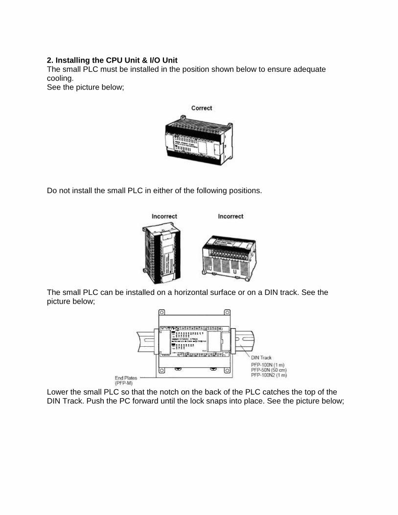
The small PLC can be installed on a horizontal surface or on a DIN track. See the picture below;
Lower the small PLC so that the notch on the back of the PLC catches the top of the DIN Track. Push the PC forward until the lock snaps into place. See the picture below;

For the big PLC before installing, the Units have to compiled one by one. There is no single Unit that can be said to constitute a Rack PLC. To build a Rack PLC, we start with a Backplane. The Backplane for the Omron PLC is shown below.
The Backplane is a simple device having two functions. The first is to provide physical support for the Units to be mounted to it. The second is to provide the connectors and electrical pathways necessary for connecting the Units mounted to it. The core of the PLC is the CPU. The CPU contains the program consisting of the series of steps necessary for the control task. The CPU has a built-in power supply, and fits into the rightmost position of the Backplane.
The CPU of the big PLC has no I/O points built in. So, in order to complete the PLC we need to mount one or more I/O Units to the Backplane. Mount the I/O Unit to the Backplane by locking the top of the I/O Unit into the slot on the Backplane and rotating the I/O Unit downwards as shown in the following diagram. Press down on the yellow tab at the bottom of the slot, press the I/O Unit firmly into position, and then release the yellow tab.

The figure below shows one I/O Unit mounted directly to the left of the CPU.
I/O Units are where the control connections are made from the PLC to all the various input devices and output devices. As you can see from the figure above, there is still some space available on the left side of the Backplane. This space is for any additional I/O Units that may be required.The figure below shows a total of eight I/O Units mounted to the Backplane.
After the big PLC compiled in the backplane then the big PLC can be installed on the DIN Rail. The DIN Rail Mounting Bracket shown below is necessary for mounting the PLC to the DIN Rail.
The following diagram is a view of the back of the Backplane. Attach one Mounting Bracket to the left and right sides of the Backplane as shown below.

Mount the Backplane to the DIN Rail so that the claws on the Mounting Brackets fit into the upper portion of the DIN Rail as shown below.
Loosen the screws attaching the Mounting Brackets to the Backplane. Slide the Backplane upward as shown below so that the Mounting Bracket and Backplane clamp securely onto the DIN Rail. Tighten the screws.
3. Installing the Expansion Unit or Expansion I/O Unit The Expansion Unit or Expansion I/O Unit are usually attached when amount of I/O devices to be controlled increase its amount over than capacities of the existing I/O Unit or attached when needed to a special need like temperature sensor. The following shown the example of Expansion Units.

Expansion Unit of the small PLC
Expansion Unit of the big PLC
For the small PLC use the following procedure when connecting an Expansion Unit or Expansion I/O Unit;Remove the cover from the CPU Unit’s or the Expansion I/O Unit’s expansion connector. Use a flat-blade screwdriver to remove the cover from the Expansion I/O Connector.
Insert the Expansion I/O Unit’s connecting cable into the CPU Unit’s or the Expansion I/O Unit’s expansion connector.

Replace the cover on the CPU Unit’s or the Expansion I/O Unit’s expansion connector.
For the big PLC use the following picture when connecting an Expansion Unit or Expansion I/O Unit;
4. Installing I/O devices I/O devices are attached at the place have been determined in the work plan and wiring

diagram. For switches are usually attached at the panel while the sensor, selenoid and motor is usually placed at the machine to be controlled. 5. Wiring and connections Duct Work Hanging Ducts If power cables carrying more than 10 A 400 V, or 20 A 220 V must be run alongside the I/O wiring (that is, in parallel with it), at least 300 mm must be left between the power cables and the I/O wiring as shown below.
Floor Ducts If the I/O wiring and power cables must be placed in the same duct (for example, where they are connected to the equipment), they must be shielded from each other using grounded metal plates.

Conduits if Separating the PLC I/O lines, power and control lines, and power cables, as shown in the following diagram.
I/O connections Connect the I/O Devices to the I/O Units. Use 1.25-mm2 cables or larger The terminals have screws with 3.5-mm diameter heads and self-raising pressure plates. Connect the lead wires to the terminals as shown below. Tighten the screws with a torque of 0.8 N _ m.
If you wish to attach solderless type terminals to the ends of the lead wires, use terminals having the dimensions shown below.
The following diagrams show the input configurations. This input configuration depend on specification of the Input Unit will be used. See the specification before install.

The following diagrams show the input configurations. This output configuration depend on specification of the Output Unit will be used. See the specification before install.
Power supply wiring The following example show the proper way to connect the power source to the PLC. Use 1.25-mm2 cables or larger. The terminal blocks have screws with 3.5-mm diameter heads and self-raising pressure plates. For connecting to the terminal blocks, use round crimp terminals for 3.5-mm diameter heads. Directly connecting stranded wires to the terminal blocks may cause a short-circuit.

Power supply wiring on the Omron PLC
Grounding This PLC has sufficient protection against noise, so it can be used without grounding except for special much noise. However, when grounding it should be done conforming to below items. Ground the PLC as independently as possible. Class 3 grounding should be used (grounding resistance 100Ω or less). When independent grounding is impossible, use the joint grounding method as shown in the figure below (B). Use thicker grounding wire. Grounding point should be as near as possible to the PLC to minimize the distance of grounding cable. See the picture below;
Checking the work and making the report
Inspecting installation
After Installation has been done then done inspection of the work quality and wiring. This matter
is executed by checking every extension cables at devices and compared with the wiring
diagram which has been prepared. Checking extension cables and devices are done by using
the assistive equipment like the multimeter and testpen.
Matters which require to be paid attention to in inspection for example:

Whether all Units of the PLC and I/O devices have been attached truly? Whether all cables and connectors have been attached compactly according to the
wiring diagram and jam in lickety split? Are there Loose terminal screws? Are there Loose connectors?
Testing installation
Several items which require to be tested in installation of the PLC for example;
Wiring input
Wiring input can be tested by connecting all input devices and see the indicator lamp on Input
Units of the PLC. Wiring input of the PLC can be told goodness if the indicator lamp on Input
Units is ON.
Wiring output
Wiring output can be tested by using force instruction to output terminal of the PLC. The
instruction can be used without waiting the program has been made and can be separated
without damage the existing program if the PLC has been programmed.
The following example show forcing at the Omron PLC;
Connect the Programming Console, set the mode switch to PROGRAM mode, and turn ON the PLC
Enter the password by press
Enter the force instruction by press
see the picture below;

Forcing instruction
Grounding resistance, Insulation resistance, Polarity
Grounding resistance, and polarity can be tested by using the Multimeter while insulation
resistance can be tested by using the Mega ohmmeter. For the grounding resistance has to less
than 100 ohm, for the insulation resistance has to more than 1 Megaohm/volt. The polarity of
DC voltage require to be retested to prevent the happening of inversed polarity which can
destroy the equipments.
Making the report
The report is made for documentation. With the good documentation and depository of the good
administration peripheral, we will be more easy to look for the archives nor things which we
need.
Posted by AGUNG at 8:30 AM