Embed Size (px)
Citation preview
Components, System
s, &
Connections
fourC H A P T E R
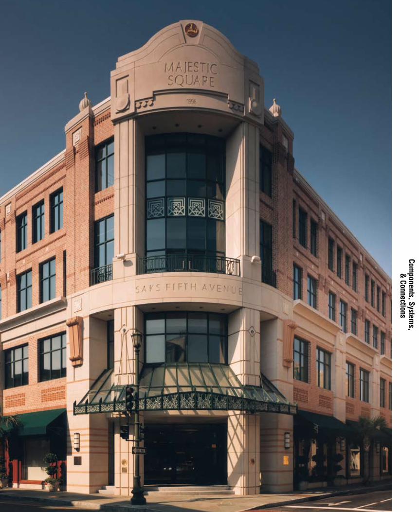
C O M P O N E N T S , S Y S T E M S , & C O N N E C T I O N S
Components ____________ 4A
Precast Concrete Systems __4B
Connections ____________ 4C
D E S I G N I N G W I T H P R E C A S T & P R E S T R E S S E D C O N C R E T E
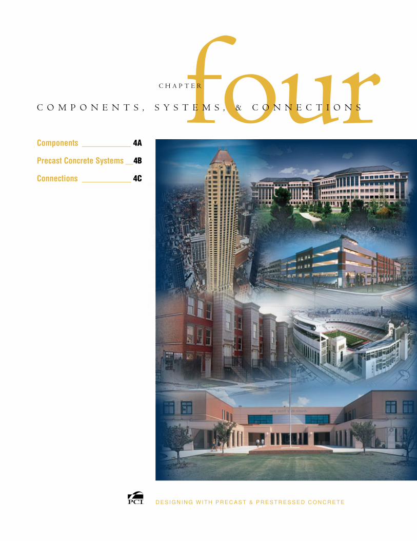
University Village, Chicago, Ill.; Architect: FitzGerald Associates
Architects; Photo: The Spancrete Group.
A total of 2101 components were used consisting
of 1550 hollow-core planks, 226 precast inverted-T beams,
100 precast columns, 144 pieces of precast shear wall,
26 pieces of precast porches, and 45 pieces of balcony beams.
a•C H A P T E R F O U R
C O M P O N E N T S
A variety of components can be fabricated from precast concrete, meeting a range of project needs. Listed here are the most common components that precast concrete manufacturers produce and that designers incorporate into their projects. Customized pieces, sizes, and shapes can be created in many cases to meet specific programmatic needs.
The designer should consult with the local precaster early in the design phase to determine what components will work most efficiently and to review specific sizes, joint locations, and other details that can create cost effective options.
D E S I G N I N G W I T H P R E C A S T & P R E S T R E S S E D C O N C R E T E 4A-1
ResouRces:Chapter 11.1.3, “Beam Design Equations and Diagrams,” MNL-120-04: PCI Design Handbook, Sixth Edition.Chapter 4.0, “Structural Design,” MNL-129-98: Precast Prestressed Concrete Parking Structures: Recommended Practice for Design and Construction.Chapter 4.5.3, “Beams,” MNL-129-98: Precast Prestressed Concrete Parking Structures: Recom-mended Practice for Design and Construction.
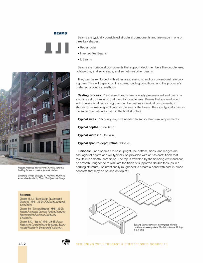
Precast balconies alternate with porches along the building façade to create a dynamic rhythm.
University Village, Chicago, Ill.; Architect: FitzGerald Associates Architects; Photo: The Spancrete Group.
Balcony beams were cast as one piece with the cantilevered balcony slabs. The balconies are 12 ft by 6 ft in plan.
BeamsBeams are typically considered structural components and are made in one of
three key shapes:
• Rectangular
• Inverted Tee Beams
• L Beams
Beams are horizontal components that support deck members like double tees, hollow-core, and solid slabs, and sometimes other beams.
They can be reinforced with either prestressing strand or conventional reinforc-ing bars. This will depend on the spans, loading conditions, and the producer’s preferred production methods.
Casting process: Prestressed beams are typically pretensioned and cast in a long-line set up similar to that used for double tees. Beams that are reinforced with conventional reinforcing bars can be cast as individual components, in shorter forms made specifically for the size of the beam. They are typically cast in the same orientation as used in the final structure.
Typical sizes: Practically any size needed to satisfy structural requirements.
Typical depths: 16 to 40 in.
Typical widths: 12 to 24 in.
Typical span-to-depth ratios: 10 to 20.
Finishes: Since beams are cast upright, the bottom, sides, and ledges are cast against a form and will typically be provided with an “as cast” finish that results in a smooth, hard finish. The top is troweled by the finishing crew and can be smooth, roughened to simulate the finish of supported double tees (as in a parking structure), or intentionally roughened to create a bond with cast-in-place concrete that may be poured on top of it.
D E S I G N I N G W I T H P R E C A S T & P R E S T R E S S E D C O N C R E T E4A-2
C O M P O N E N T S
ResouRces:Chapter 7.2.1.2, “Column Covers and Mullions,” MNL-120-04: PCI Design Handbook, Sixth Edition.Chapter 2, Section 2.4 “Precast Concrete Panels Used as Cladding.” MNL-122-07: PCI Architectural Precast Concrete Manual, Third Edition.Chapter 4.2.4, “Design Considerations for Non-Loadbearing Wall Panels,” MNL-122-07: PCI Architectural Precast Concrete Manual, Third Edition.
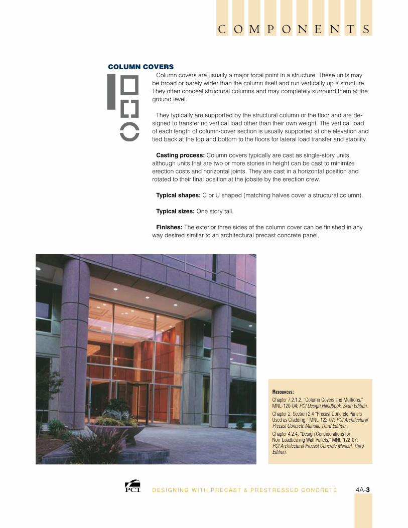
Column CoversColumn covers are usually a major focal point in a structure. These units may
be broad or barely wider than the column itself and run vertically up a structure. They often conceal structural columns and may completely surround them at the ground level.
They typically are supported by the structural column or the floor and are de-signed to transfer no vertical load other than their own weight. The vertical load of each length of column-cover section is usually supported at one elevation and tied back at the top and bottom to the floors for lateral load transfer and stability.
Casting process: Column covers typically are cast as single-story units, although units that are two or more stories in height can be cast to minimize erection costs and horizontal joints. They are cast in a horizontal position and rotated to their final position at the jobsite by the erection crew.
Typical shapes: C or U shaped (matching halves cover a structural column).
Typical sizes: One story tall.
Finishes: The exterior three sides of the column cover can be finished in any way desired similar to an architectural precast concrete panel.
D E S I G N I N G W I T H P R E C A S T & P R E S T R E S S E D C O N C R E T E 4A-3
ResouRces:Chapter 4.9, “Compression Members,” MNL-120-04: PCI Design Handbook, Sixth Edition.
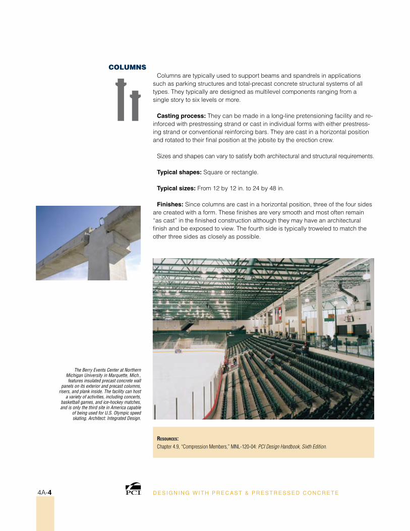
The Berry Events Center at Northern Michigan University in Marquette, Mich., features insulated precast concrete wall
panels on its exterior and precast columns, risers, and plank inside. The facility can host
a variety of activities, including concerts, basketball games, and ice-hockey matches, and is only the third site in America capable
of being used for U.S. Olympic speed skating. Architect: Integrated Design.
ColumnsColumns are typically used to support beams and spandrels in applications
such as parking structures and total-precast concrete structural systems of all types. They typically are designed as multilevel components ranging from a single story to six levels or more.
Casting process: They can be made in a long-line pretensioning facility and re-inforced with prestressing strand or cast in individual forms with either prestress-ing strand or conventional reinforcing bars. They are cast in a horizontal position and rotated to their final position at the jobsite by the erection crew.
Sizes and shapes can vary to satisfy both architectural and structural requirements.
Typical shapes: Square or rectangle.
Typical sizes: From 12 by 12 in. to 24 by 48 in.
Finishes: Since columns are cast in a horizontal position, three of the four sides are created with a form. These finishes are very smooth and most often remain “as cast” in the finished construction although they may have an architectural finish and be exposed to view. The fourth side is typically troweled to match the other three sides as closely as possible.
D E S I G N I N G W I T H P R E C A S T & P R E S T R E S S E D C O N C R E T E4A-4
C O M P O N E N T S
ResouRces:Chapter 2.4, “Stemmed Deck Members,” MNL-120-04: PCI Design Handbook, Sixth Edition.Chapter 4.5.1, “Stemmed Floor Members,” MNL-129-98: Precast Prestressed Concrete Parking Structures: Recommended Practice for Design and Construction.Chapter 4.6, “Pretopped Double Tees,” MNL-129-98: Precast Prestressed Concrete Parking Structures: Recommended Practice for Design and Construction.
PCI Journal:“New Mega Tee Passes Load Testing,” PCI Journal; March-April 1997, pp. 136-139.
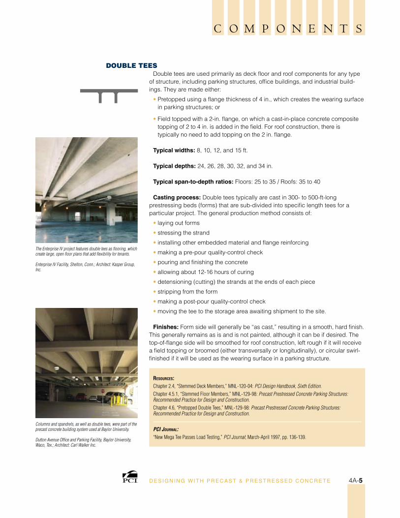
The Enterprise IV project features double tees as flooring, which create large, open floor plans that add flexibility for tenants.
Enterprise IV Facility, Shelton, Conn.; Architect: Kasper Group, Inc.
Columns and spandrels, as well as double tees, were part of the precast concrete building system used at Baylor University.
Dutton Avenue Office and Parking Facility, Baylor University, Waco, Tex.; Architect: Carl Walker Inc.
DouBle TeesDouble tees are used primarily as deck floor and roof components for any type
of structure, including parking structures, office buildings, and industrial build-ings. They are made either:
• Pretopped using a flange thickness of 4 in., which creates the wearing surface in parking structures; or
• Field topped with a 2-in. flange, on which a cast-in-place concrete composite topping of 2 to 4 in. is added in the field. For roof construction, there is typically no need to add topping on the 2 in. flange.
Typical widths: 8, 10, 12, and 15 ft.
Typical depths: 24, 26, 28, 30, 32, and 34 in.
Typical span-to-depth ratios: Floors: 25 to 35 / Roofs: 35 to 40
Casting process: Double tees typically are cast in 300- to 500-ft-long prestressing beds (forms) that are sub-divided into specific length tees for a particular project. The general production method consists of:
• laying out forms
• stressing the strand
• installing other embedded material and flange reinforcing
• making a pre-pour quality-control check
• pouring and finishing the concrete
• allowing about 12-16 hours of curing
• detensioning (cutting) the strands at the ends of each piece
• stripping from the form
• making a post-pour quality-control check
• moving the tee to the storage area awaiting shipment to the site.
Finishes: Form side will generally be “as cast,” resulting in a smooth, hard finish. This generally remains as is and is not painted, although it can be if desired. The top-of-flange side will be smoothed for roof construction, left rough if it will receive a field topping or broomed (either transversally or longitudinally), or circular swirl-finished if it will be used as the wearing surface in a parking structure.
D E S I G N I N G W I T H P R E C A S T & P R E S T R E S S E D C O N C R E T E 4A-5
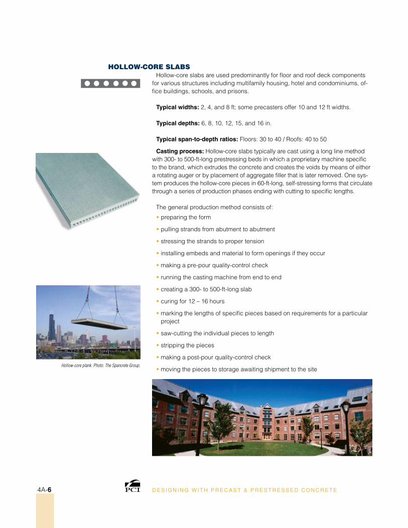
Hollow-core plank. Photo: The Spancrete Group.
Hollow-Core slaBsHollow-core slabs are used predominantly for floor and roof deck components
for various structures including multifamily housing, hotel and condominiums, of-fice buildings, schools, and prisons.
Typical widths: 2, 4, and 8 ft; some precasters offer 10 and 12 ft widths.
Typical depths: 6, 8, 10, 12, 15, and 16 in.
Typical span-to-depth ratios: Floors: 30 to 40 / Roofs: 40 to 50
Casting process: Hollow-core slabs typically are cast using a long line method with 300- to 500-ft-long prestressing beds in which a proprietary machine specific to the brand, which extrudes the concrete and creates the voids by means of either a rotating auger or by placement of aggregate filler that is later removed. One sys-tem produces the hollow-core pieces in 60-ft-long, self-stressing forms that circulate through a series of production phases ending with cutting to specific lengths.
The general production method consists of:
• preparing the form
• pulling strands from abutment to abutment
• stressing the strands to proper tension
• installing embeds and material to form openings if they occur
• making a pre-pour quality-control check
• running the casting machine from end to end
• creating a 300- to 500-ft-long slab
• curing for 12 – 16 hours
• marking the lengths of specific pieces based on requirements for a particular project
• saw-cutting the individual pieces to length
• stripping the pieces
• making a post-pour quality-control check
• moving the pieces to storage awaiting shipment to the site
D E S I G N I N G W I T H P R E C A S T & P R E S T R E S S E D C O N C R E T E4A-6
C O M P O N E N T S
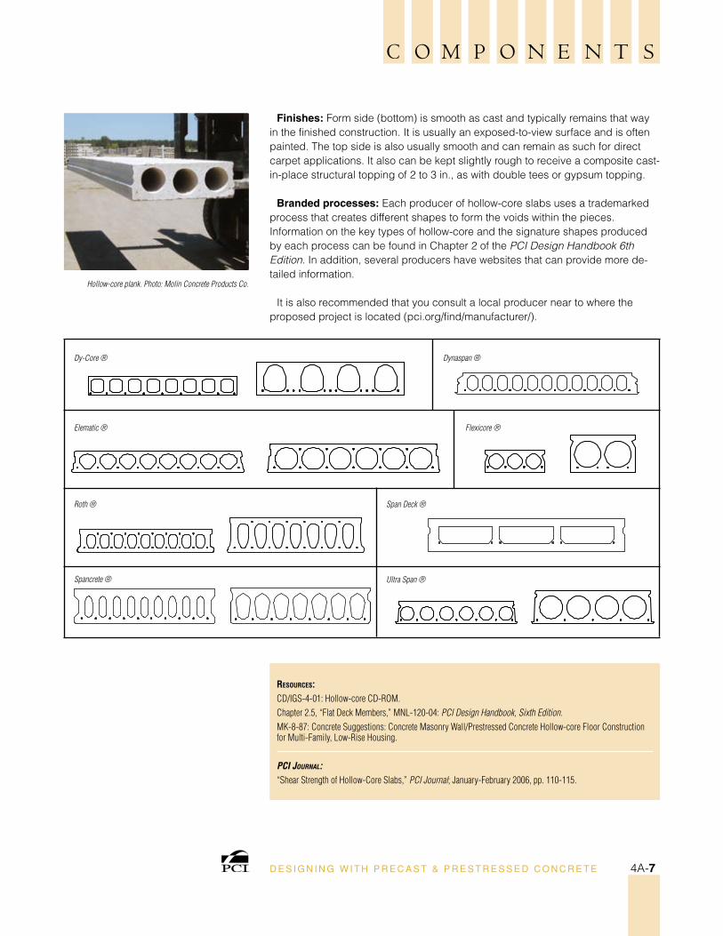
Hollow-core plank. Photo: Molin Concrete Products Co.
ResouRces:CD/IGS-4-01: Hollow-core CD-ROM.Chapter 2.5, “Flat Deck Members,” MNL-120-04: PCI Design Handbook, Sixth Edition.MK-8-87: Concrete Suggestions: Concrete Masonry Wall/Prestressed Concrete Hollow-core Floor Construction for Multi-Family, Low-Rise Housing.
PCI Journal:“Shear Strength of Hollow-Core Slabs,” PCI Journal; January-February 2006, pp. 110-115.
Roth ®
Dynaspan ®Dy-Core ®
Spancrete ®
Elematic ® Flexicore ®
Span Deck ®
Ultra Span ®
Finishes: Form side (bottom) is smooth as cast and typically remains that way in the finished construction. It is usually an exposed-to-view surface and is often painted. The top side is also usually smooth and can remain as such for direct carpet applications. It also can be kept slightly rough to receive a composite cast-in-place structural topping of 2 to 3 in., as with double tees or gypsum topping.
Branded processes: Each producer of hollow-core slabs uses a trademarked process that creates different shapes to form the voids within the pieces. Information on the key types of hollow-core and the signature shapes produced by each process can be found in Chapter 2 of the PCI Design Handbook 6th Edition. In addition, several producers have websites that can provide more de-tailed information.
It is also recommended that you consult a local producer near to where the proposed project is located (pci.org/find/manufacturer/).
D E S I G N I N G W I T H P R E C A S T & P R E S T R E S S E D C O N C R E T E 4A-7
ResouRces:Chapter 9.4, “Sandwich Panels,” MNL-120-04: PCI Design Handbook, Sixth Edition.Chapter 5, Section 5.3.8, “Precast Concrete Sandwich Panels,” MNL-122-07: PCI Architectural Precast Concrete Manual, Third Edition.MK-14-98: Precast Concrete Wall Panels: Sandwich Wall Panels (6 pp.).
PCI Journal:“Analytical Investigation of Thermal Performance of Precast Concrete Three-Wythe Sandwich Wall Panels,” PCI Journal; July-August 2004, pp. 88-101.
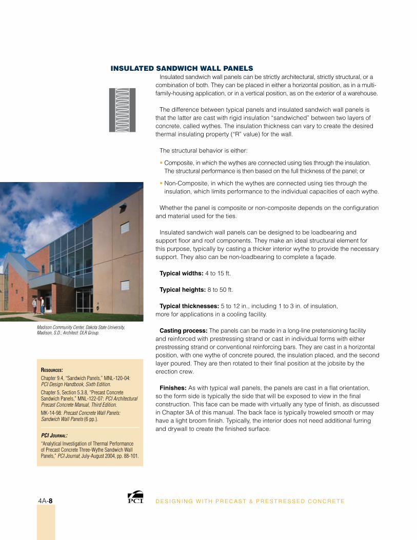
Madison Community Center, Dakota State University, Madison, S.D.; Architect: DLR Group.
InsulaTeD sanDwICH wall PanelsInsulated sandwich wall panels can be strictly architectural, strictly structural, or a
combination of both. They can be placed in either a horizontal position, as in a multi-family-housing application, or in a vertical position, as on the exterior of a warehouse.
The difference between typical panels and insulated sandwich wall panels is that the latter are cast with rigid insulation “sandwiched” between two layers of concrete, called wythes. The insulation thickness can vary to create the desired thermal insulating property (“R” value) for the wall.
The structural behavior is either:
• Composite, in which the wythes are connected using ties through the insulation. The structural performance is then based on the full thickness of the panel; or
• Non-Composite, in which the wythes are connected using ties through the insulation, which limits performance to the individual capacities of each wythe.
Whether the panel is composite or non-composite depends on the configuration and material used for the ties.
Insulated sandwich wall panels can be designed to be loadbearing and support floor and roof components. They make an ideal structural element for this purpose, typically by casting a thicker interior wythe to provide the necessary support. They also can be non-loadbearing to complete a façade.
Typical widths: 4 to 15 ft.
Typical heights: 8 to 50 ft.
Typical thicknesses: 5 to 12 in., including 1 to 3 in. of insulation, more for applications in a cooling facility.
Casting process: The panels can be made in a long-line pretensioning facility and reinforced with prestressing strand or cast in individual forms with either prestressing strand or conventional reinforcing bars. They are cast in a horizontal position, with one wythe of concrete poured, the insulation placed, and the second layer poured. They are then rotated to their final position at the jobsite by the erection crew.
Finishes: As with typical wall panels, the panels are cast in a flat orientation, so the form side is typically the side that will be exposed to view in the final construction. This face can be made with virtually any type of finish, as discussed in Chapter 3A of this manual. The back face is typically troweled smooth or may have a light broom finish. Typically, the interior does not need additional furring and drywall to create the finished surface.
D E S I G N I N G W I T H P R E C A S T & P R E S T R E S S E D C O N C R E T E4A-8
C O M P O N E N T S
ResouRces:Chapter 1.2.2, “Parking Structures,” MNL-120-04: PCI Design Handbook, Sixth Edition.Chapter 3.5, “Shear Wall Systems,” MNL-120-04: PCI Design Handbook, Sixth Edition.Chapter 1.4.1.2.1, “Framing Systems,” MNL-129-98: Precast Prestressed Concrete Parking Structures: Recommended Practice for Design and Construction.
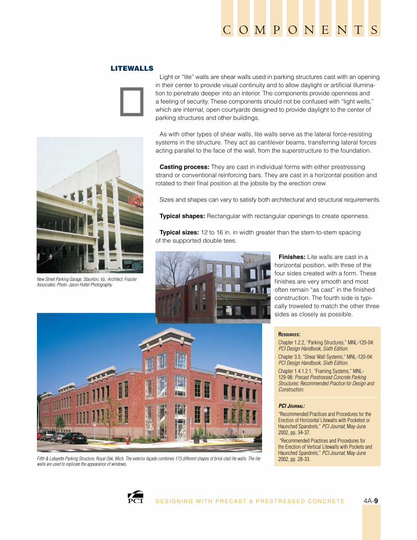
PCI Journal:“Recommended Practices and Procedures for the Erection of Horizontal Litewalls with Pocketed or Haunched Spandrels,” PCI Journal; May-June 2002, pp. 34-37. “Recommended Practices and Procedures for the Erection of Vertical Litewalls with Pockets and Haunched Spandrels,” PCI Journal; May-June 2002, pp. 28-33.Fifth & Lafayette Parking Structure, Royal Oak, Mich. The exterior façade combines 173 different shapes of brick clad lite walls. The lite
walls are used to replicate the appearance of windows.
New Street Parking Garage, Staunton, Va.; Architect: Fraizier Associates; Photo: Jason Hottel Photography.
lITewallsLight or “lite” walls are shear walls used in parking structures cast with an opening
in their center to provide visual continuity and to allow daylight or artificial illumina-tion to penetrate deeper into an interior. The components provide openness and a feeling of security. These components should not be confused with “light wells,” which are internal, open courtyards designed to provide daylight to the center of parking structures and other buildings.
As with other types of shear walls, lite walls serve as the lateral force-resisting systems in the structure. They act as cantilever beams, transferring lateral forces acting parallel to the face of the wall, from the superstructure to the foundation.
Casting process: They are cast in individual forms with either prestressing strand or conventional reinforcing bars. They are cast in a horizontal position and rotated to their final position at the jobsite by the erection crew.
Sizes and shapes can vary to satisfy both architectural and structural requirements.
Typical shapes: Rectangular with rectangular openings to create openness.
Typical sizes: 12 to 16 in. in width greater than the stem-to-stem spacing of the supported double tees.
Finishes: Lite walls are cast in a horizontal position, with three of the four sides created with a form. These finishes are very smooth and most often remain “as cast” in the finished construction. The fourth side is typi-cally troweled to match the other three sides as closely as possible.
D E S I G N I N G W I T H P R E C A S T & P R E S T R E S S E D C O N C R E T E 4A-9
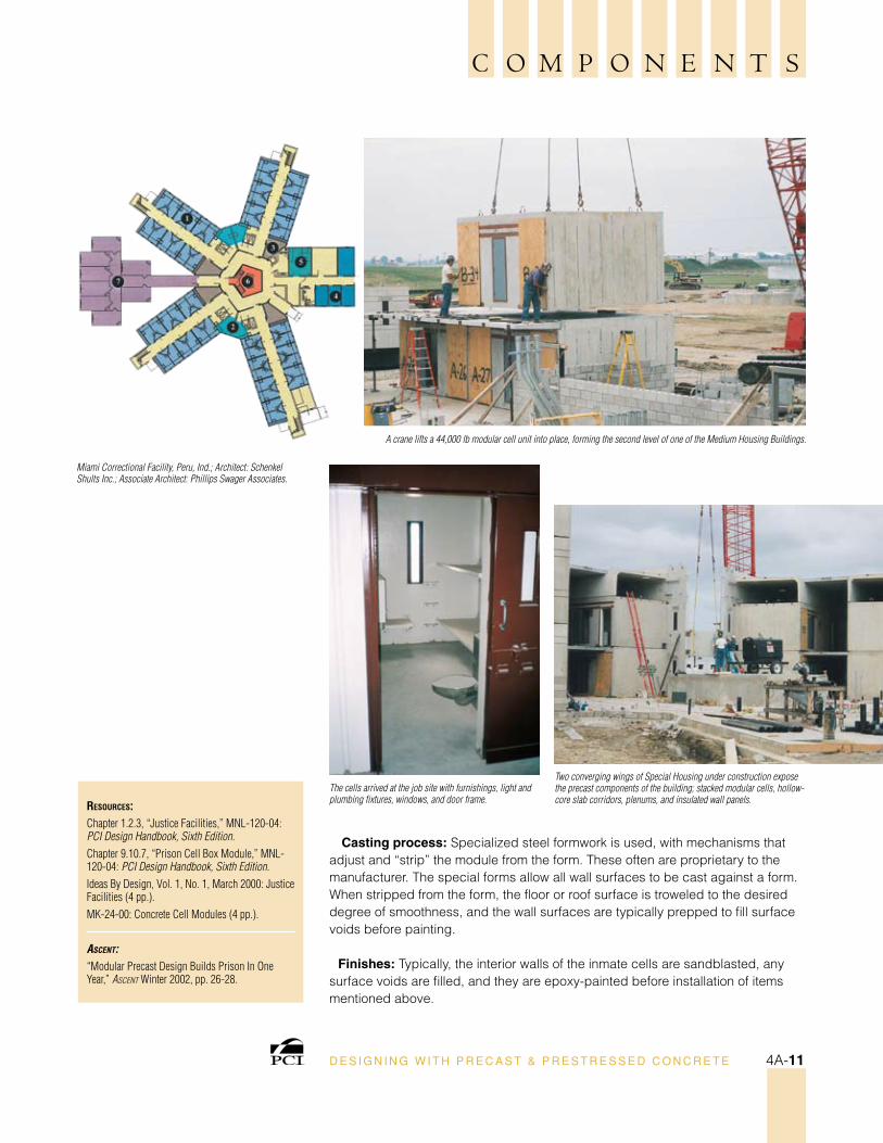
Precast concrete modular classrooms lend an air of permanecy not found in typical trailer-type portable units, yet they retain the feel of conventional classrooms.
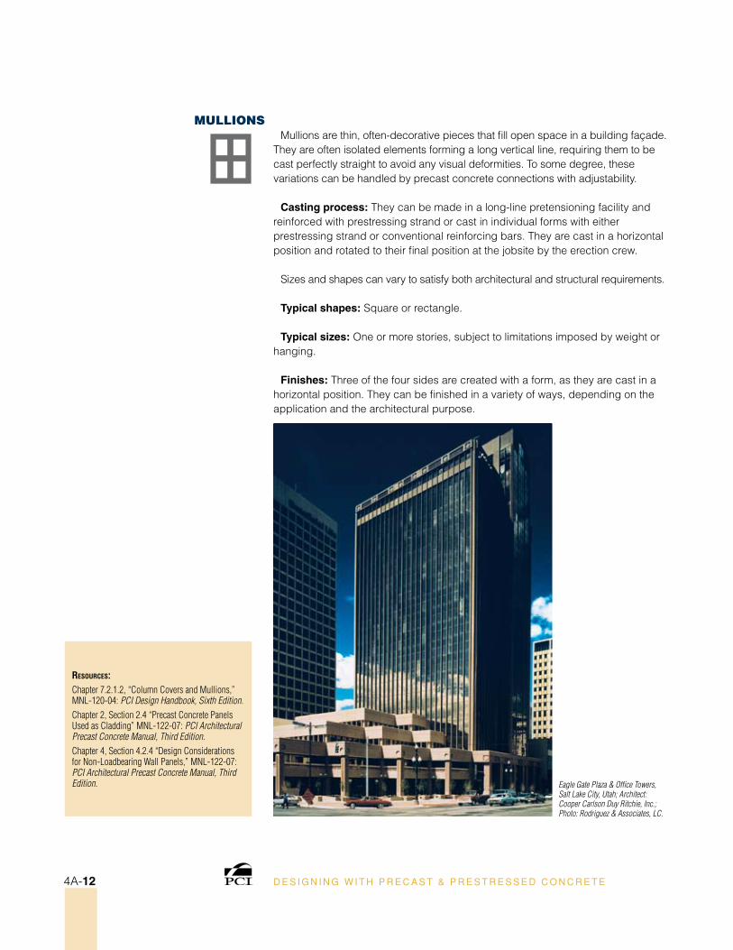
A crane hoists one of the 30-ft modules into place on the concrete foundation. The modules were delivered at night under
a police escort because of daytime congestion in the area.
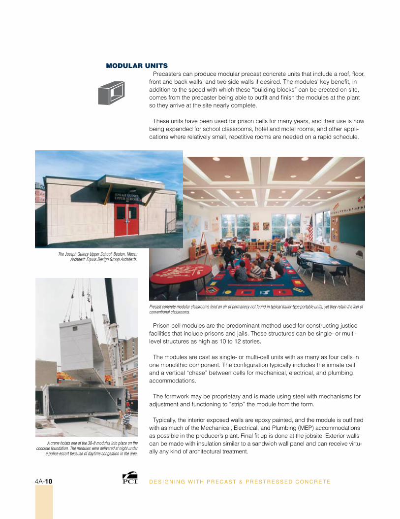
moDular unITsPrecasters can produce modular precast concrete units that include a roof, floor,
front and back walls, and two side walls if desired. The modules’ key benefit, in addition to the speed with which these “building blocks” can be erected on site, comes from the precaster being able to outfit and finish the modules at the plant so they arrive at the site nearly complete.
These units have been used for prison cells for many years, and their use is now being expanded for school classrooms, hotel and motel rooms, and other appli-cations where relatively small, repetitive rooms are needed on a rapid schedule.
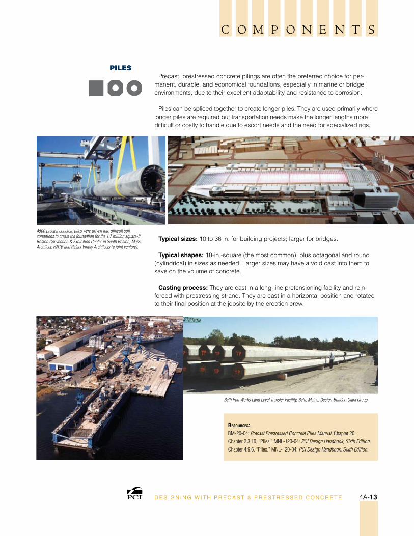
Prison-cell modules are the predominant method used for constructing justice facilities that include prisons and jails. These structures can be single- or multi-level structures as high as 10 to 12 stories.
The modules are cast as single- or multi-cell units with as many as four cells in one monolithic component. The configuration typically includes the inmate cell and a vertical “chase” between cells for mechanical, electrical, and plumbing accommodations.
The formwork may be proprietary and is made using steel with mechanisms for adjustment and functioning to “strip” the module from the form.
Typically, the interior exposed walls are epoxy painted, and the module is outfitted with as much of the Mechanical, Electrical, and Plumbing (MEP) accommodations as possible in the producer’s plant. Final fit up is done at the jobsite. Exterior walls can be made with insulation similar to a sandwich wall panel and can receive virtu-ally any kind of architectural treatment.
D E S I G N I N G W I T H P R E C A S T & P R E S T R E S S E D C O N C R E T E4A-10
The Joseph Quincy Upper School, Boston, Mass.;Architect: Equus Design Group Architects.
C O M P O N E N T S
ResouRces:Chapter 1.2.3, “Justice Facilities,” MNL-120-04: PCI Design Handbook, Sixth Edition.Chapter 9.10.7, “Prison Cell Box Module,” MNL-120-04: PCI Design Handbook, Sixth Edition.Ideas By Design, Vol. 1, No. 1, March 2000: Justice Facilities (4 pp.).MK-24-00: Concrete Cell Modules (4 pp.).
asCent:“Modular Precast Design Builds Prison In One Year,” Ascent Winter 2002, pp. 26-28.
Two converging wings of Special Housing under construction expose the precast components of the building; stacked modular cells, hollow-core slab corridors, plenums, and insulated wall panels.
A crane lifts a 44,000 lb modular cell unit into place, forming the second level of one of the Medium Housing Buildings.
Casting process: Specialized steel formwork is used, with mechanisms that adjust and “strip” the module from the form. These often are proprietary to the manufacturer. The special forms allow all wall surfaces to be cast against a form. When stripped from the form, the floor or roof surface is troweled to the desired degree of smoothness, and the wall surfaces are typically prepped to fill surface voids before painting.
Finishes: Typically, the interior walls of the inmate cells are sandblasted, any surface voids are filled, and they are epoxy-painted before installation of items mentioned above.
D E S I G N I N G W I T H P R E C A S T & P R E S T R E S S E D C O N C R E T E 4A-11
The cells arrived at the job site with furnishings, light and plumbing fixtures, windows, and door frame.
Miami Correctional Facility, Peru, Ind.; Architect: Schenkel Shults Inc.; Associate Architect: Phillips Swager Associates.
ResouRces:Chapter 7.2.1.2, “Column Covers and Mullions,” MNL-120-04: PCI Design Handbook, Sixth Edition.Chapter 2, Section 2.4 “Precast Concrete Panels Used as Cladding” MNL-122-07: PCI Architectural Precast Concrete Manual, Third Edition.Chapter 4, Section 4.2.4 “Design Considerations for Non-Loadbearing Wall Panels,” MNL-122-07: PCI Architectural Precast Concrete Manual, Third Edition. Eagle Gate Plaza & Office Towers,
Salt Lake City, Utah; Architect: Cooper Carlson Duy Ritchie, Inc.; Photo: Rodriguez & Associates, LC.
mullIonsMullions are thin, often-decorative pieces that fill open space in a building façade.
They are often isolated elements forming a long vertical line, requiring them to be cast perfectly straight to avoid any visual deformities. To some degree, these variations can be handled by precast concrete connections with adjustability.
Casting process: They can be made in a long-line pretensioning facility and reinforced with prestressing strand or cast in individual forms with either prestressing strand or conventional reinforcing bars. They are cast in a horizontal position and rotated to their final position at the jobsite by the erection crew.
Sizes and shapes can vary to satisfy both architectural and structural requirements.
Typical shapes: Square or rectangle.
Typical sizes: One or more stories, subject to limitations imposed by weight or hanging.
Finishes: Three of the four sides are created with a form, as they are cast in a horizontal position. They can be finished in a variety of ways, depending on the application and the architectural purpose.
D E S I G N I N G W I T H P R E C A S T & P R E S T R E S S E D C O N C R E T E4A-12
C O M P O N E N T S
ResouRces:BM-20-04: Precast Prestressed Concrete Piles Manual, Chapter 20.Chapter 2.3.10, “Piles,” MNL-120-04: PCI Design Handbook, Sixth Edition.Chapter 4.9.6, “Piles,” MNL-120-04: PCI Design Handbook, Sixth Edition.
Bath Iron Works Land Level Transfer Facility, Bath, Maine; Design-Builder: Clark Group.
4500 precast concrete piles were driven into difficult soil conditions to create the foundation for the 1.7 million square-ft Boston Convention & Exhibition Center in South Boston, Mass. Architect: HNTB and Rafael Vinoly Architects (a joint venture).
PIlesPrecast, prestressed concrete pilings are often the preferred choice for per-
manent, durable, and economical foundations, especially in marine or bridge environments, due to their excellent adaptability and resistance to corrosion.
Piles can be spliced together to create longer piles. They are used primarily where longer piles are required but transportation needs make the longer lengths more difficult or costly to handle due to escort needs and the need for specialized rigs.
Typical sizes: 10 to 36 in. for building projects; larger for bridges.
Typical shapes: 18-in.-square (the most common), plus octagonal and round (cylindrical) in sizes as needed. Larger sizes may have a void cast into them to save on the volume of concrete.
Casting process: They are cast in a long-line pretensioning facility and rein-forced with prestressing strand. They are cast in a horizontal position and rotated to their final position at the jobsite by the erection crew.
D E S I G N I N G W I T H P R E C A S T & P R E S T R E S S E D C O N C R E T E 4A-13
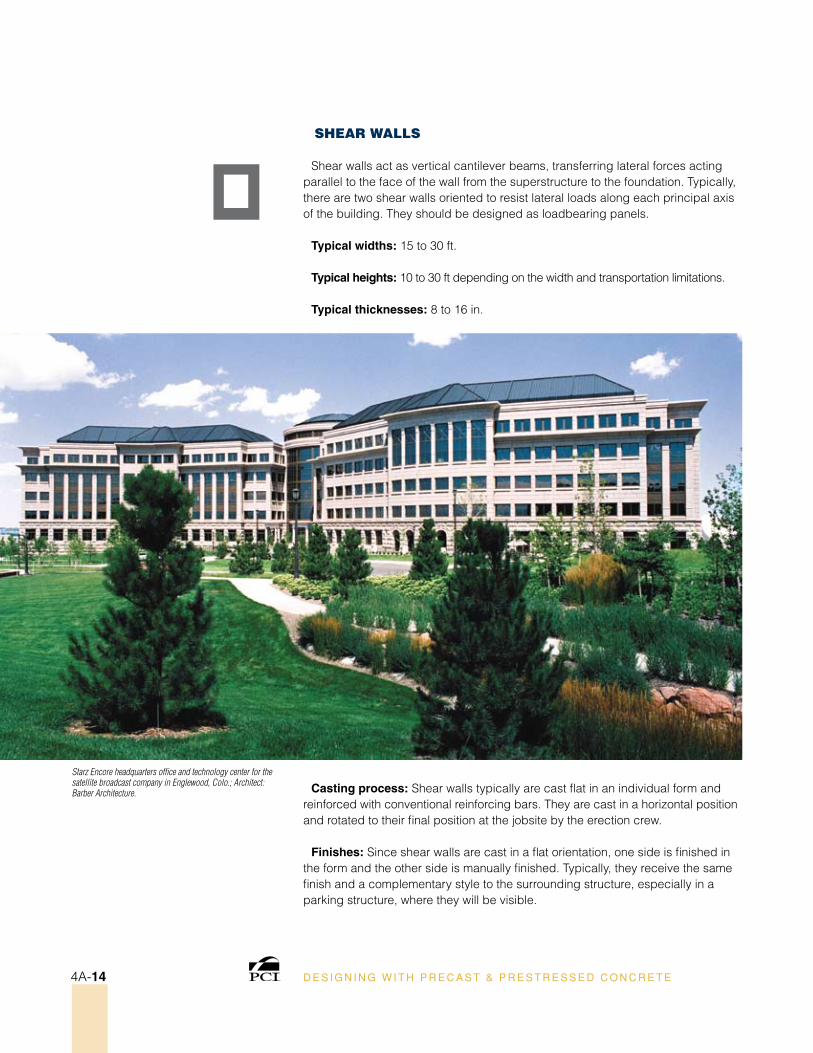
Starz Encore headquarters office and technology center for the satellite broadcast company in Englewood, Colo.; Architect: Barber Architecture.
sHear walls
Shear walls act as vertical cantilever beams, transferring lateral forces acting parallel to the face of the wall from the superstructure to the foundation. Typically, there are two shear walls oriented to resist lateral loads along each principal axis of the building. They should be designed as loadbearing panels.
Typical widths: 15 to 30 ft.
Typical heights: 10 to 30 ft depending on the width and transportation limitations.
Typical thicknesses: 8 to 16 in.
Casting process: Shear walls typically are cast flat in an individual form and reinforced with conventional reinforcing bars. They are cast in a horizontal position and rotated to their final position at the jobsite by the erection crew.
Finishes: Since shear walls are cast in a flat orientation, one side is finished in the form and the other side is manually finished. Typically, they receive the same finish and a complementary style to the surrounding structure, especially in a parking structure, where they will be visible.
D E S I G N I N G W I T H P R E C A S T & P R E S T R E S S E D C O N C R E T E4A-14
C O M P O N E N T S
ResouRces:Chapter 3.5, “Shear Wall Systems,” MNL-120-04: PCI Design Handbook, Sixth Edition.Chapter 4.3.2.3, “Shear Walls,” MNL-129-98: Precast Prestressed Concrete Parking Structures: Recommended Practice for Design and Construction.
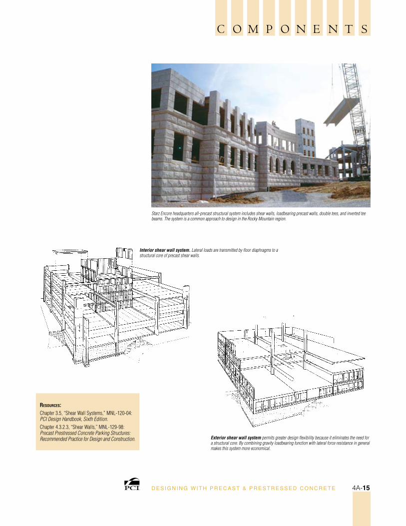
Starz Encore headquarters all-precast structural system includes shear walls, loadbearing precast walls, double tees, and inverted tee beams. The system is a common approach to design in the Rocky Mountain region.
Interior shear wall system. Lateral loads are transmitted by floor diaphragms to a structural core of precast shear walls.
Exterior shear wall system permits greater design flexibility because it eliminates the need for a structural core. By combining gravity loadbearing function with lateral force resistance in general makes this system more economical.
D E S I G N I N G W I T H P R E C A S T & P R E S T R E S S E D C O N C R E T E 4A-15
ResouRces:Chapter 2.5, “Solid Flat Slab Load Tables,” MNL-120-04: PCI Design Handbook, Sixth Edition.
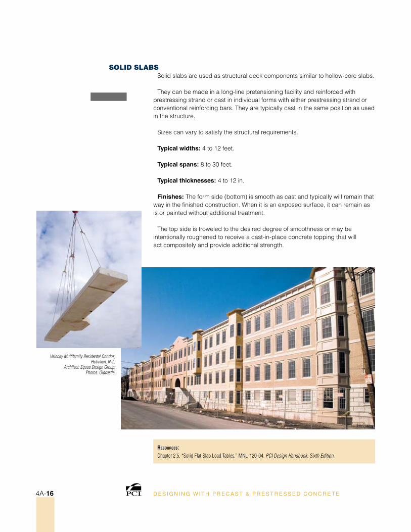
Velocity Multifamily Residental Condos, Hoboken, N.J.;
Architect: Equus Design Group; Photos: Oldcastle.
solID slaBsSolid slabs are used as structural deck components similar to hollow-core slabs.
They can be made in a long-line pretensioning facility and reinforced with prestressing strand or cast in individual forms with either prestressing strand or conventional reinforcing bars. They are typically cast in the same position as used in the structure.
Sizes can vary to satisfy the structural requirements.
Typical widths: 4 to 12 feet.
Typical spans: 8 to 30 feet.
Typical thicknesses: 4 to 12 in.
Finishes: The form side (bottom) is smooth as cast and typically will remain that way in the finished construction. When it is an exposed surface, it can remain as is or painted without additional treatment.
The top side is troweled to the desired degree of smoothness or may be intentionally roughened to receive a cast-in-place concrete topping that will act compositely and provide additional strength.
D E S I G N I N G W I T H P R E C A S T & P R E S T R E S S E D C O N C R E T E4A-16
C O M P O N E N T S
ResouRces:Chapter 7.2.1.1, “Spandrels,” MNL-120-04: PCI Design Handbook, Sixth Edition.Chapter 7.2.2.1, “Spandrels,” MNL-120-04: PCI Design Handbook, Sixth Edition.Chapter 4, Section 4.2.6, “Design Considerations for Non-Loadbearing Spandrels,” MNL-122-07: PCI Architectural Precast Concrete Manual, Third Edition.Chapter 4, Section 4.2.7, “Design Considerations for Loadbearing Spandrels,” MNL-122-07: PCI Architectural Precast Concrete Manual, Third Edition.Chapter 1.3, “Façade Treatments,” MNL-129-98: Precast Prestressed Concrete Parking Structures: Recommended Practice for Design and Construction.
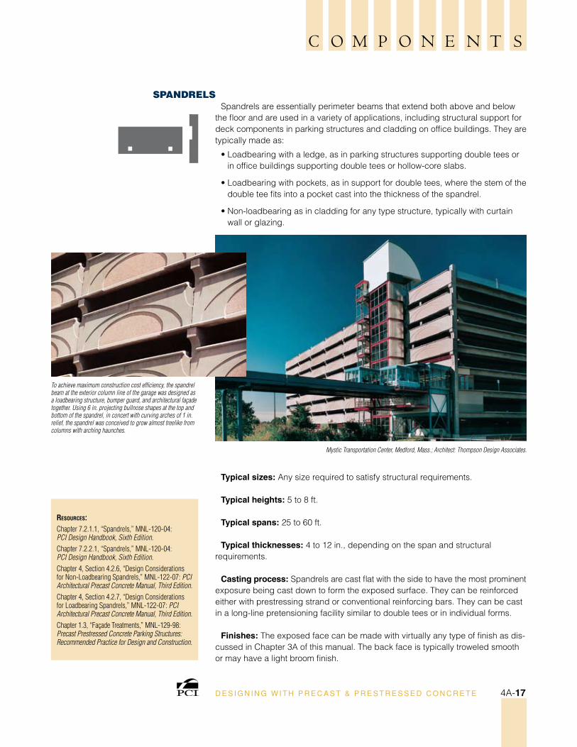
To achieve maximum construction cost efficiency, the spandrel beam at the exterior column line of the garage was designed as a loadbearing structure, bumper guard, and architectural façade together. Using 6 in. projecting bullnose shapes at the top and bottom of the spandrel, in concert with curving arches of 1 in. relief, the spandrel was conceived to grow almost treelike from columns with arching haunches.
Mystic Transportation Center, Medford, Mass.; Architect: Thompson Design Associates.
sPanDrelsSpandrels are essentially perimeter beams that extend both above and below
the floor and are used in a variety of applications, including structural support for deck components in parking structures and cladding on office buildings. They are typically made as:
• Loadbearing with a ledge, as in parking structures supporting double tees or in office buildings supporting double tees or hollow-core slabs.
• Loadbearing with pockets, as in support for double tees, where the stem of the double tee fits into a pocket cast into the thickness of the spandrel.
• Non-loadbearing as in cladding for any type structure, typically with curtain wall or glazing.
Typical sizes: Any size required to satisfy structural requirements.
Typical heights: 5 to 8 ft.
Typical spans: 25 to 60 ft.
Typical thicknesses: 4 to 12 in., depending on the span and structural requirements.
Casting process: Spandrels are cast flat with the side to have the most prominent exposure being cast down to form the exposed surface. They can be reinforced either with prestressing strand or conventional reinforcing bars. They can be cast in a long-line pretensioning facility similar to double tees or in individual forms.
Finishes: The exposed face can be made with virtually any type of finish as dis-cussed in Chapter 3A of this manual. The back face is typically troweled smooth or may have a light broom finish.
D E S I G N I N G W I T H P R E C A S T & P R E S T R E S S E D C O N C R E T E 4A-17
ResouRces:Chapter 1.2.5, “Stadiums/Arenas,” MNL-120-04: PCI Design Handbook, Sixth Edition.CD/IGS-3-01: Stadiums CD-ROM.Ideas By Design, Vol. 1, No. 2, December 2000: Stadium Projects (8 pp.).
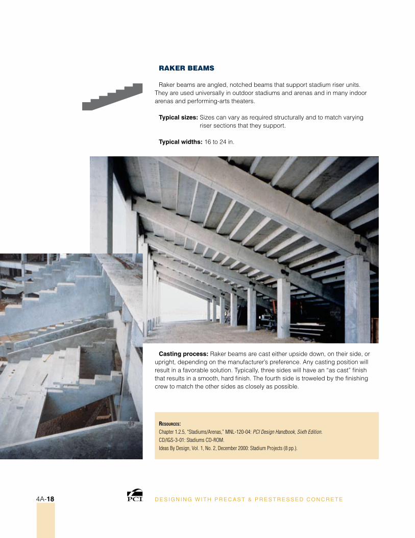
raker Beams
Raker beams are angled, notched beams that support stadium riser units. They are used universally in outdoor stadiums and arenas and in many indoor arenas and performing-arts theaters.
Typical sizes: Sizes can vary as required structurally and to match varying riser sections that they support.
Typical widths: 16 to 24 in.
Casting process: Raker beams are cast either upside down, on their side, or upright, depending on the manufacturer’s preference. Any casting position will result in a favorable solution. Typically, three sides will have an “as cast” finish that results in a smooth, hard finish. The fourth side is troweled by the finishing crew to match the other sides as closely as possible.
D E S I G N I N G W I T H P R E C A S T & P R E S T R E S S E D C O N C R E T E4A-18
C O M P O N E N T S
ResouRces:Chapter 4.2.5, “Bending of Asymmetrical Sections,” MNL-120-04: PCI Design Handbook, Sixth Edition.Figure 4.2.5.1, “Typical Stadium Riser,” MNL-120-04: PCI Design Handbook, Sixth Edition.Table 8.3.6, “Single, Double and Triple Stadium Riser Erection Tolerances,” MNL-120-04: PCI Design Handbook, Sixth Edition.Chapter 9.7.8, “Stadium Seating,” MNL-120-04: PCI Design Handbook, Sixth Edition.CD/IGS-3-01: Stadiums CD-ROM.Ideas By Design, Vol. 1, No. 2, December 2000: Stadium Projects (8 pp.).
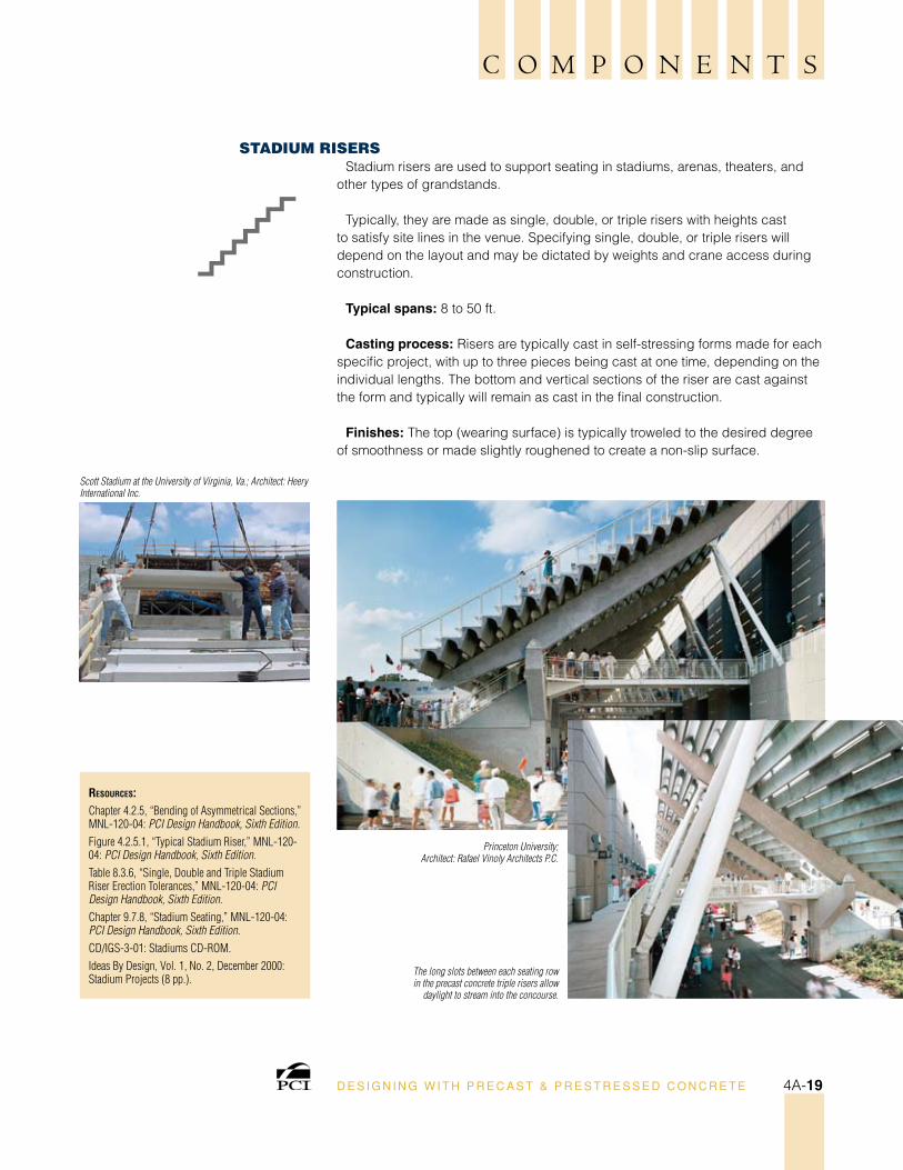
Princeton University;Architect: Rafael Vinoly Architects P.C.
Scott Stadium at the University of Virginia, Va.; Architect: Heery International Inc.
The long slots between each seating row in the precast concrete triple risers allow
daylight to stream into the concourse.
sTaDIum rIsersStadium risers are used to support seating in stadiums, arenas, theaters, and
other types of grandstands.
Typically, they are made as single, double, or triple risers with heights cast to satisfy site lines in the venue. Specifying single, double, or triple risers will depend on the layout and may be dictated by weights and crane access during construction.
Typical spans: 8 to 50 ft.
Casting process: Risers are typically cast in self-stressing forms made for each specific project, with up to three pieces being cast at one time, depending on the individual lengths. The bottom and vertical sections of the riser are cast against the form and typically will remain as cast in the final construction.
Finishes: The top (wearing surface) is typically troweled to the desired degree of smoothness or made slightly roughened to create a non-slip surface.
D E S I G N I N G W I T H P R E C A S T & P R E S T R E S S E D C O N C R E T E 4A-19
ResouRces:Table 8.3.8, “Stair Unit Erection Tolerances,” MNL-120-04: PCI Design Handbook, Sixth Edition.
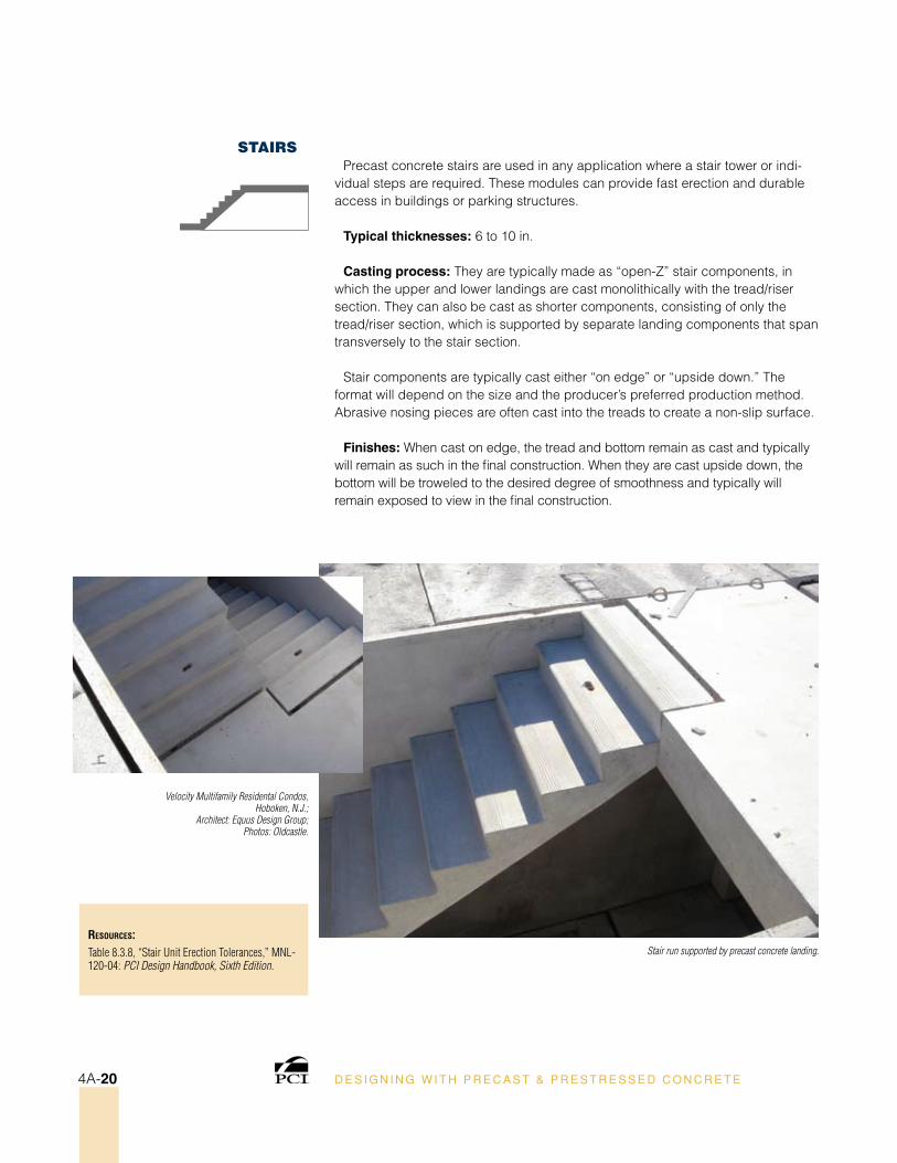
Stair run supported by precast concrete landing.
Velocity Multifamily Residental Condos, Hoboken, N.J.;
Architect: Equus Design Group; Photos: Oldcastle.
sTaIrsPrecast concrete stairs are used in any application where a stair tower or indi-
vidual steps are required. These modules can provide fast erection and durable access in buildings or parking structures.
Typical thicknesses: 6 to 10 in.
Casting process: They are typically made as “open-Z” stair components, in which the upper and lower landings are cast monolithically with the tread/riser section. They can also be cast as shorter components, consisting of only the tread/riser section, which is supported by separate landing components that span transversely to the stair section.
Stair components are typically cast either “on edge” or “upside down.” The format will depend on the size and the producer’s preferred production method. Abrasive nosing pieces are often cast into the treads to create a non-slip surface.
Finishes: When cast on edge, the tread and bottom remain as cast and typically will remain as such in the final construction. When they are cast upside down, the bottom will be troweled to the desired degree of smoothness and typically will remain exposed to view in the final construction.
D E S I G N I N G W I T H P R E C A S T & P R E S T R E S S E D C O N C R E T E4A-20
C O M P O N E N T S
ResouRces:Chapter 7.2.1.4, “Wall Panels,” MNL-120-04: PCI Design Handbook, Sixth Edition.MK-14-98: Precast Concrete Wall Panels: Sandwich Wall Panels (6 pp.).MK-15-98: Precast Concrete Wall Panels: Warehouse/Distribution Centers (6 pp.).MK-16-98: Precast Concrete Wall Panels: Manufacturing Facilities (6 pp.).MK-17-98: Precast Concrete Wall Panels: High-Tech Facilities (6 pp.).MK-18-98: Precast Concrete Wall Panels: Food-Processing Facilities (6 pp.). MK-19-98: Precast Concrete Wall Panels: Retail Buildings (6 pp.).MK-20-98: Precast Panels for Industrial Buildings (6 pp.).MNL-122-07: PCI Architectural Precast Concrete Manual, Third Edition.
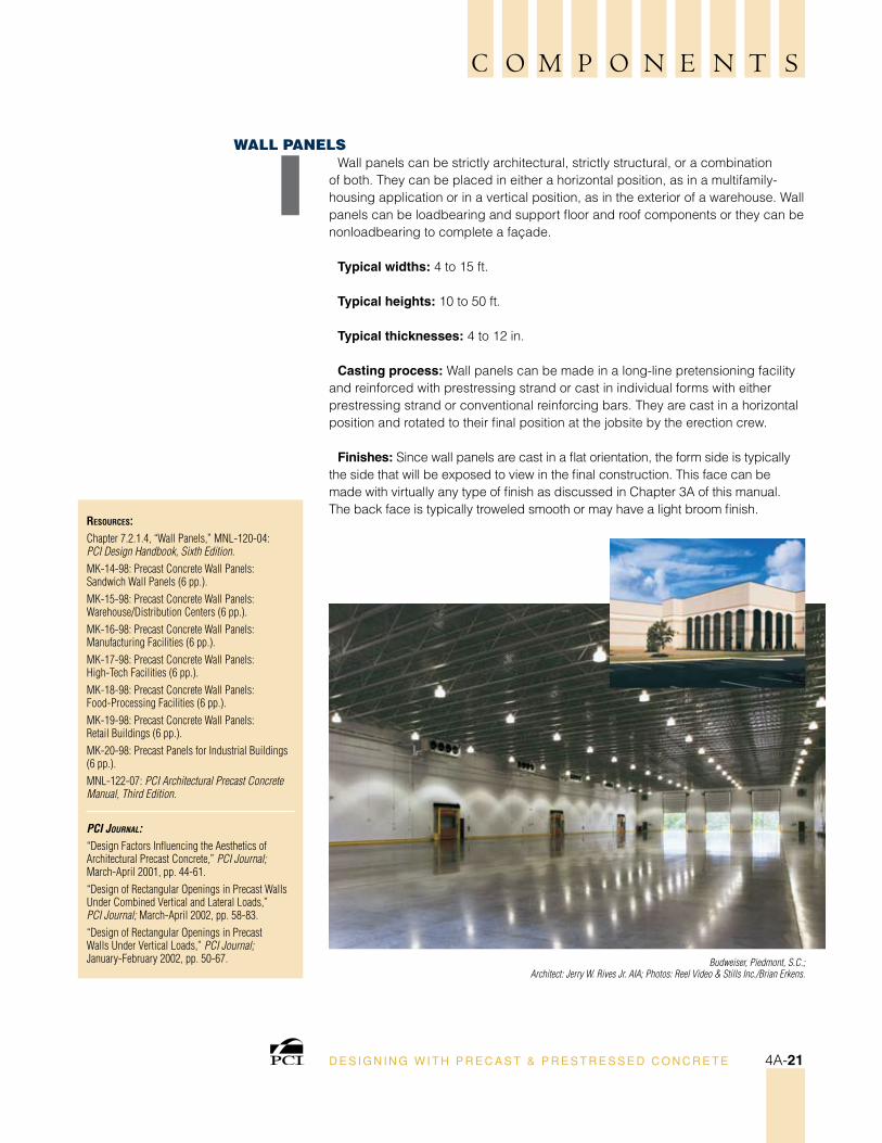
PCI Journal:“Design Factors Influencing the Aesthetics of Architectural Precast Concrete,” PCI Journal; March-April 2001, pp. 44-61.“Design of Rectangular Openings in Precast Walls Under Combined Vertical and Lateral Loads,” PCI Journal; March-April 2002, pp. 58-83.“Design of Rectangular Openings in Precast Walls Under Vertical Loads,” PCI Journal; January-February 2002, pp. 50-67. Budweiser, Piedmont, S.C.;
Architect: Jerry W. Rives Jr. AIA; Photos: Reel Video & Stills Inc./Brian Erkens.
wall PanelsWall panels can be strictly architectural, strictly structural, or a combination
of both. They can be placed in either a horizontal position, as in a multifamily-housing application or in a vertical position, as in the exterior of a warehouse. Wall panels can be loadbearing and support floor and roof components or they can be nonloadbearing to complete a façade.
Typical widths: 4 to 15 ft.
Typical heights: 10 to 50 ft.
Typical thicknesses: 4 to 12 in.
Casting process: Wall panels can be made in a long-line pretensioning facility and reinforced with prestressing strand or cast in individual forms with either prestressing strand or conventional reinforcing bars. They are cast in a horizontal position and rotated to their final position at the jobsite by the erection crew.
Finishes: Since wall panels are cast in a flat orientation, the form side is typically the side that will be exposed to view in the final construction. This face can be made with virtually any type of finish as discussed in Chapter 3A of this manual. The back face is typically troweled smooth or may have a light broom finish.
D E S I G N I N G W I T H P R E C A S T & P R E S T R E S S E D C O N C R E T E 4A-21
D E S I G N I N G W I T H P R E C A S T & P R E S T R E S S E D C O N C R E T E 4B-1
b•C H A P T E R F O U R
Precast Concrete Systems
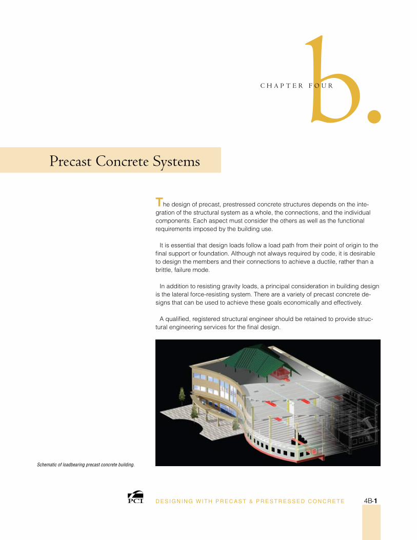
The design of precast, prestressed concrete structures depends on the inte-gration of the structural system as a whole, the connections, and the individual components. Each aspect must consider the others as well as the functional requirements imposed by the building use.
It is essential that design loads follow a load path from their point of origin to the final support or foundation. Although not always required by code, it is desirable to design the members and their connections to achieve a ductile, rather than a brittle, failure mode.
In addition to resisting gravity loads, a principal consideration in building design is the lateral force-resisting system. There are a variety of precast concrete de-signs that can be used to achieve these goals economically and effectively.
A qualified, registered structural engineer should be retained to provide struc-tural engineering services for the final design.
Schematic of loadbearing precast concrete building.
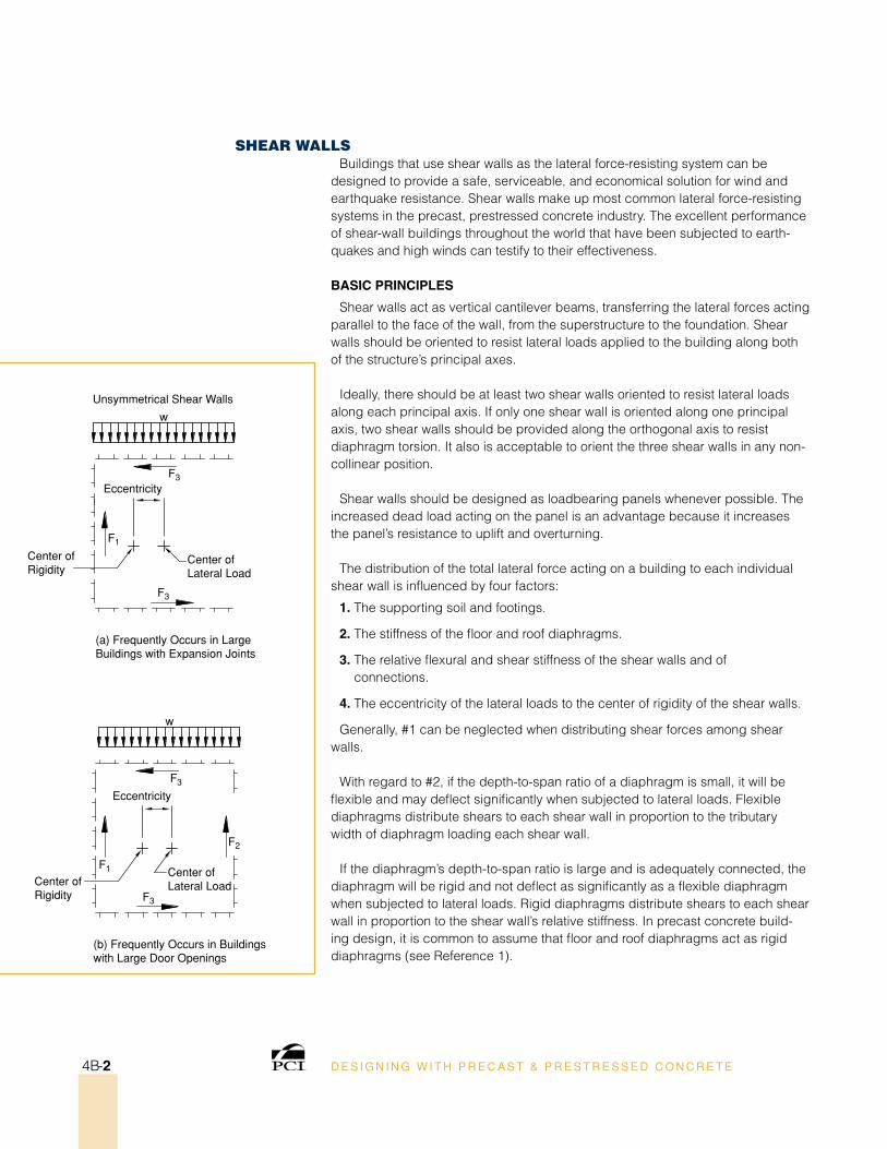
Eccentricity
Center ofRigidity
Center ofRigidity
Center ofLateral Load
Center ofLateral Load
(a) Frequently Occurs in LargeBuildings with Expansion Joints
Unsymmetrical Shear Walls
(b) Frequently Occurs in Buildings with Large Door Openings
w
F1
F3
Eccentricity
w
F1
F3
F3
F2
F3
D E S I G N I N G W I T H P R E C A S T & P R E S T R E S S E D C O N C R E T E4B-2
sHear walls Buildings that use shear walls as the lateral force-resisting system can be
designed to provide a safe, serviceable, and economical solution for wind and earthquake resistance. Shear walls make up most common lateral force-resisting systems in the precast, prestressed concrete industry. The excellent performance of shear-wall buildings throughout the world that have been subjected to earth-quakes and high winds can testify to their effectiveness.
BAsiC PrinCiPles
Shear walls act as vertical cantilever beams, transferring the lateral forces acting parallel to the face of the wall, from the superstructure to the foundation. Shear walls should be oriented to resist lateral loads applied to the building along both of the structure’s principal axes.
Ideally, there should be at least two shear walls oriented to resist lateral loads along each principal axis. If only one shear wall is oriented along one principal axis, two shear walls should be provided along the orthogonal axis to resist diaphragm torsion. It also is acceptable to orient the three shear walls in any non-collinear position.
Shear walls should be designed as loadbearing panels whenever possible. The increased dead load acting on the panel is an advantage because it increases the panel’s resistance to uplift and overturning.
The distribution of the total lateral force acting on a building to each individual shear wall is influenced by four factors:
1. The supporting soil and footings.
2. The stiffness of the floor and roof diaphragms.
3. The relative flexural and shear stiffness of the shear walls and of connections.
4. The eccentricity of the lateral loads to the center of rigidity of the shear walls.
Generally, #1 can be neglected when distributing shear forces among shear walls.
With regard to #2, if the depth-to-span ratio of a diaphragm is small, it will be flexible and may deflect significantly when subjected to lateral loads. Flexible diaphragms distribute shears to each shear wall in proportion to the tributary width of diaphragm loading each shear wall.
If the diaphragm’s depth-to-span ratio is large and is adequately connected, the diaphragm will be rigid and not deflect as significantly as a flexible diaphragm when subjected to lateral loads. Rigid diaphragms distribute shears to each shear wall in proportion to the shear wall’s relative stiffness. In precast concrete build-ing design, it is common to assume that floor and roof diaphragms act as rigid diaphragms (see Reference 1).
D E S I G N I N G W I T H P R E C A S T & P R E S T R E S S E D C O N C R E T E 4B-3
PreCAsT ConCreTe Designs
The design for precast concrete shear walls typically has followed principles used for cast-in-place structures, with modifications made as appropriate for the jointed nature of a precast concrete structural system. Design methods used to achieve successful performance of precast shear-wall structures have been left largely to the judgment of the structural engineer.
Observations of performance of structures in earthquakes show that where adequate strength and stiffness were provided to limit interstory drift (lateral displacement) to about 2% (relative to a point at the story below), the resulting displacements and damage were within acceptable levels.
In regions of low and moderate seismic activity, bolted or welded connections with small grout joints are generally used. In regions of high seismic activity, connections to the foundation and connections between precast concrete walls generally use details that emulate cast-in-place behavior and may include post-tensioning (see Reference 2).
Design guiDelines
The steps in designing structures that have shear walls as the primary lateral load-resisting elements include eight key steps that are carried out by the structural engineer of record (EOR) or the precast concrete specialty engineer subject to the EOR’s approval:
evaluate the building function and applicable precast concrete frame. In a warehouse-type structure, for instance, it is common to include the exterior walls as part of the lateral force-resisting system. In parking structures, shear walls can be located at stair and elevator towers, at the ends of ramped bays, at selected locations on the perimeter of the structure, or at any combination of the above.
Develop a preliminary design for the shear-wall system. This requires six steps:
1. Provide at least three non-collinear walls to ensure torsional as well as direct lateral resistance.
2. Determine if shear walls can also function as bearing walls, as overturning often will be the governing criterion.
3. Arrange shear walls so they minimize restraint due to volume changes.
4. Consider whether the shear walls could be individual full-height walls (vertical joints only).
5. Consider the practicality of transportation and erection when selecting the size of wall panels.
6. Balance the design requirements of the shear walls with the design require-ments of the associated diaphragms.
ResouRces:MNL-120-04: PCI Design Handbook, Sixth Edition.
1. Chapter 3.5.2, “Shear Wall Systems: Principles of Shear Wall Buildings,” MNL-120-04: PCI Design Handbook, Sixth Edition.
2. Chapter 3.5.1, “Shear Wall Systems: Introduc-tion,” MNL-120-04: PCI Design Handbook, Sixth Edition.
3. “Chapter 3.5.4, “Design Guidelines for Shear Wall Structures,” MNL-120-04: PCI Design Handbook, Sixth Edition.
RefeRences:
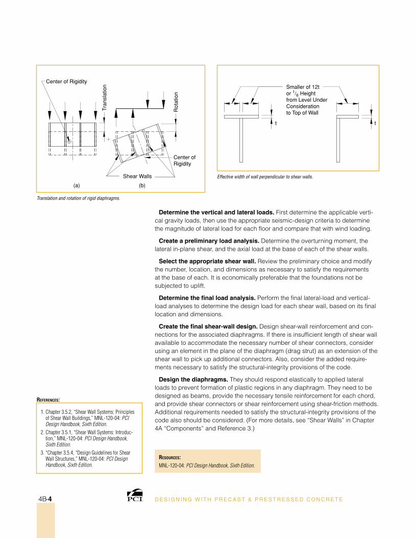
Center of Rigidity
Center of Rigidity
Shear Walls
Tran
slat
ion
Rot
atio
n
(a) (b)
Smaller of 12tor 1/6 Heightfrom Level UnderConsiderationto Top of Wall
t t
D E S I G N I N G W I T H P R E C A S T & P R E S T R E S S E D C O N C R E T E4B-4
Determine the vertical and lateral loads. First determine the applicable verti-cal gravity loads, then use the appropriate seismic-design criteria to determine the magnitude of lateral load for each floor and compare that with wind loading.
Create a preliminary load analysis. Determine the overturning moment, the lateral in-plane shear, and the axial load at the base of each of the shear walls.
select the appropriate shear wall. Review the preliminary choice and modify the number, location, and dimensions as necessary to satisfy the requirements at the base of each. It is economically preferable that the foundations not be subjected to uplift.
Determine the final load analysis. Perform the final lateral-load and vertical-load analyses to determine the design load for each shear wall, based on its final location and dimensions.
Create the final shear-wall design. Design shear-wall reinforcement and con-nections for the associated diaphragms. If there is insufficient length of shear wall available to accommodate the necessary number of shear connectors, consider using an element in the plane of the diaphragm (drag strut) as an extension of the shear wall to pick up additional connectors. Also, consider the added require-ments necessary to satisfy the structural-integrity provisions of the code.
Design the diaphragms. They should respond elastically to applied lateral loads to prevent formation of plastic regions in any diaphragm. They need to be designed as beams, provide the necessary tensile reinforcement for each chord, and provide shear connectors or shear reinforcement using shear-friction methods. Additional requirements needed to satisfy the structural-integrity provisions of the code also should be considered. (For more details, see “Shear Walls” in Chapter 4A “Components” and Reference 3.)
Translation and rotation of rigid diaphragms.
Effective width of wall perpendicular to shear walls.
D E S I G N I N G W I T H P R E C A S T & P R E S T R E S S E D C O N C R E T E 4B-5
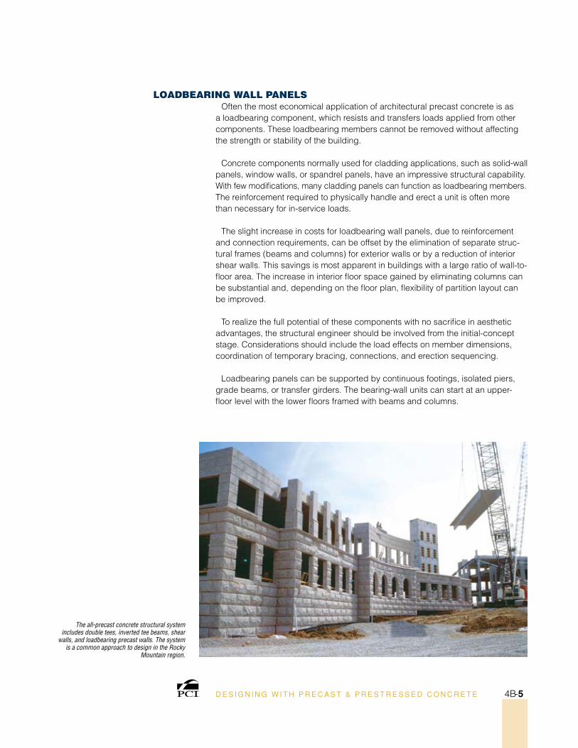
loaDBearIng wall PanelsOften the most economical application of architectural precast concrete is as
a loadbearing component, which resists and transfers loads applied from other components. These loadbearing members cannot be removed without affecting the strength or stability of the building.
Concrete components normally used for cladding applications, such as solid-wall panels, window walls, or spandrel panels, have an impressive structural capability. With few modifications, many cladding panels can function as loadbearing members. The reinforcement required to physically handle and erect a unit is often more than necessary for in-service loads.
The slight increase in costs for loadbearing wall panels, due to reinforcement and connection requirements, can be offset by the elimination of separate struc-tural frames (beams and columns) for exterior walls or by a reduction of interior shear walls. This savings is most apparent in buildings with a large ratio of wall-to-floor area. The increase in interior floor space gained by eliminating columns can be substantial and, depending on the floor plan, flexibility of partition layout can be improved.
To realize the full potential of these components with no sacrifice in aesthetic advantages, the structural engineer should be involved from the initial-concept stage. Considerations should include the load effects on member dimensions, coordination of temporary bracing, connections, and erection sequencing.
Loadbearing panels can be supported by continuous footings, isolated piers, grade beams, or transfer girders. The bearing-wall units can start at an upper-floor level with the lower floors framed with beams and columns.
The all-precast concrete structural system includes double tees, inverted tee beams, shear
walls, and loadbearing precast walls. The system is a common approach to design in the Rocky
Mountain region.
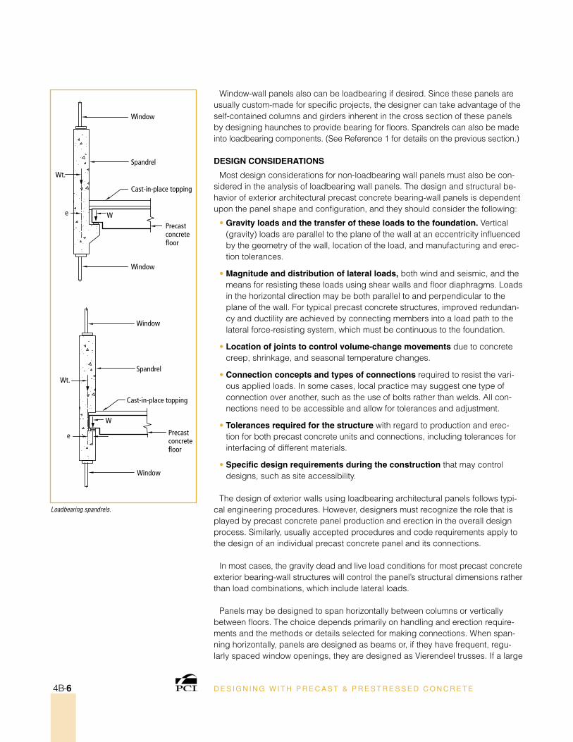
Loadbearing spandrels.
D E S I G N I N G W I T H P R E C A S T & P R E S T R E S S E D C O N C R E T E4B-6
Cast-in-place topping
Spandrel
Window
Window
Precast concrete floor
e W
Wt.
Cast-in-place topping
Spandrel
Window
Window
Precast concrete floor
e
W
Wt.
Window-wall panels also can be loadbearing if desired. Since these panels are usually custom-made for specific projects, the designer can take advantage of the self-contained columns and girders inherent in the cross section of these panels by designing haunches to provide bearing for floors. Spandrels can also be made into loadbearing components. (See Reference 1 for details on the previous section.)
Design ConsiDerATions
Most design considerations for non-loadbearing wall panels must also be con-sidered in the analysis of loadbearing wall panels. The design and structural be-havior of exterior architectural precast concrete bearing-wall panels is dependent upon the panel shape and configuration, and they should consider the following:
• gravity loads and the transfer of these loads to the foundation. Vertical (gravity) loads are parallel to the plane of the wall at an eccentricity influenced by the geometry of the wall, location of the load, and manufacturing and erec-tion tolerances.
• Magnitude and distribution of lateral loads, both wind and seismic, and the means for resisting these loads using shear walls and floor diaphragms. Loads in the horizontal direction may be both parallel to and perpendicular to the plane of the wall. For typical precast concrete structures, improved redundan-cy and ductility are achieved by connecting members into a load path to the lateral force-resisting system, which must be continuous to the foundation.
• location of joints to control volume-change movements due to concrete creep, shrinkage, and seasonal temperature changes.
• Connection concepts and types of connections required to resist the vari-ous applied loads. In some cases, local practice may suggest one type of connection over another, such as the use of bolts rather than welds. All con-nections need to be accessible and allow for tolerances and adjustment.
• Tolerances required for the structure with regard to production and erec-tion for both precast concrete units and connections, including tolerances for interfacing of different materials.
• specific design requirements during the construction that may control designs, such as site accessibility.
The design of exterior walls using loadbearing architectural panels follows typi-cal engineering procedures. However, designers must recognize the role that is played by precast concrete panel production and erection in the overall design process. Similarly, usually accepted procedures and code requirements apply to the design of an individual precast concrete panel and its connections.
In most cases, the gravity dead and live load conditions for most precast concrete exterior bearing-wall structures will control the panel’s structural dimensions rather than load combinations, which include lateral loads.
Panels may be designed to span horizontally between columns or vertically between floors. The choice depends primarily on handling and erection require-ments and the methods or details selected for making connections. When span-ning horizontally, panels are designed as beams or, if they have frequent, regu-larly spaced window openings, they are designed as Vierendeel trusses. If a large
ResouRces:MNL-120-04: PCI Design Handbook, Sixth Edition.PCI MNL-122-07: Architectural Precast Concrete, Third Edition.
1. Chapter 2, Section 2.6, “Loadbearing Wall Panels or Spandrels,” PCI MNL-122-07: Architectural Precast Concrete, Third Edition.
2. Chapter 4, Section 4.2.5, “Design Considerations for Loadbearing Wall Panels,” PCI MNL-122-07: Architectural Precast Concrete, Third Edition.
RefeRences:
D E S I G N I N G W I T H P R E C A S T & P R E S T R E S S E D C O N C R E T E 4B-7
portion of the panel contains window openings, it may be necessary to analyze it as a rigid frame (see Reference 2).
shAPes AnD Finishes
In multistory buildings, the loadbearing wall panels can be several stories in height up to the maximum transportable length, or they can be one-story high and connect at every floor level. The architectural requirements generally govern the design. The variety of shapes and surface finishes commonly associated with cladding can be provided, if the structural and other technical requirements can be satisfied.
By extending loadbearing panels vertically through several stories, complex connection details are minimized and the economic advantages of loadbearing wall panels are increased.
Architectural requirements normally dictate that building elevations have wall panels of the same appearance. As a result, the wall panels receiving the greatest gravity loads should be determined and panel units should be designed inter-changeably with the same reinforcing in all panels. This allows any panel to be installed at any point on the structure’s exterior, since the floor plan of a loadbear-ing panel building is usually the same on all stories, producing uniform loads on the building perimeter.
In most cases, there is little need to be concerned with differential foundation settlement. This is one of the most important advantages for high-rise, loadbear-ing panel structures where the bearing walls also serve as shear walls.
momenT-resIsTIng BuIlDIng FramesMoment-resisting frames are those in which a degree of rotational restraint is
provided between vertical components (usually columns) and horizontal com-ponents (usually beams and/or spandrels). This system then resists lateral loads imposed on the structure.
Precast, prestressed concrete beams and deck members are usually more eco-nomical when they are designed and connected into a structure as simple-span members. There are three reasons why this works most effectively:
1. Positive moment-resisting capacity is much easier and less expensive to achieve with pretensioned members than negative-moment capacity at sup-ports.
2. Connections that achieve continuity at the supports are usually complex. Their cost is proportional to the complexity that makes moment-resistant frames less attractive for designers.
ResouRces:IBC-1-01: Impact of the Seismic Design Provisions of the International Building Code, MNL-120-04: PCI Design Handbook, Sixth Edition.
PCI Journal:“Ductile Connections in Precast Concrete Moment Resisting Frames,” PCI Journal, May-June 2006, pp. 66-77.
1. Chapter 3.6, “Moment-Resisting Building Frames,” MNL-120-04: PCI Design Handbook, Sixth Edition.
RefeRences:
D E S I G N I N G W I T H P R E C A S T & P R E S T R E S S E D C O N C R E T E4B-8
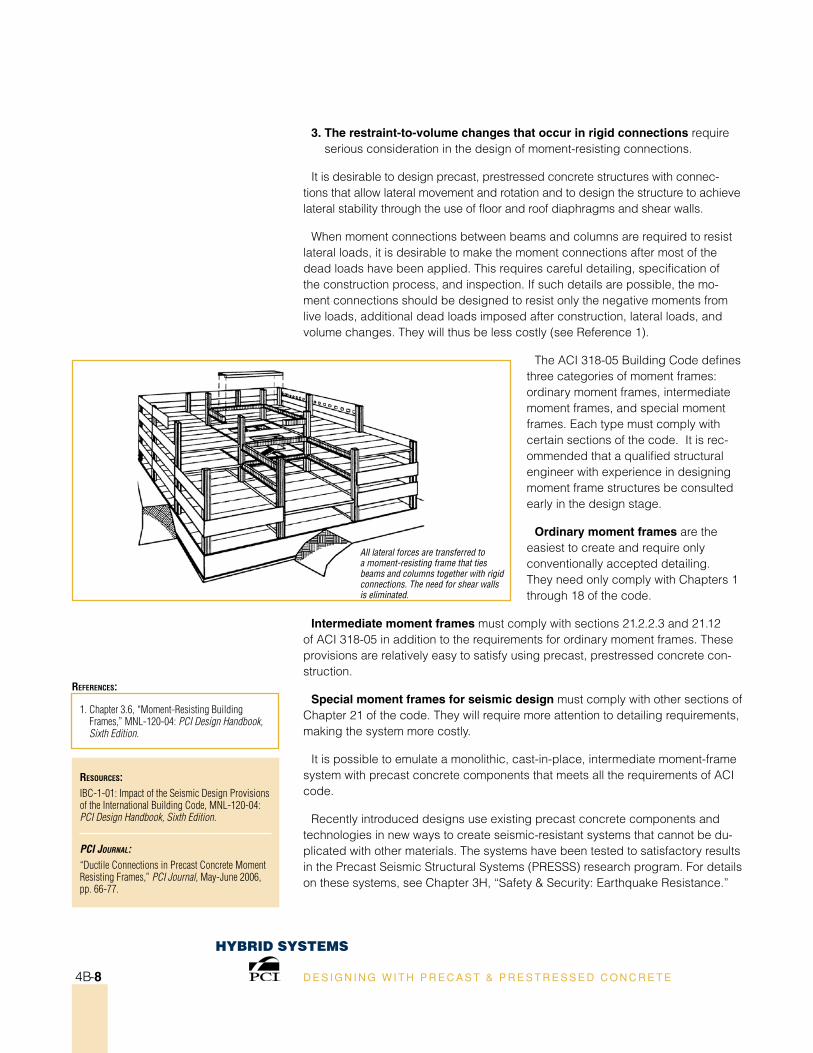
All lateral forces are transferred to a moment-resisting frame that ties beams and columns together with rigid connections. The need for shear walls is eliminated.
3. The restraint-to-volume changes that occur in rigid connections require serious consideration in the design of moment-resisting connections.
It is desirable to design precast, prestressed concrete structures with connec-tions that allow lateral movement and rotation and to design the structure to achieve lateral stability through the use of floor and roof diaphragms and shear walls.
When moment connections between beams and columns are required to resist lateral loads, it is desirable to make the moment connections after most of the dead loads have been applied. This requires careful detailing, specification of the construction process, and inspection. If such details are possible, the mo-ment connections should be designed to resist only the negative moments from live loads, additional dead loads imposed after construction, lateral loads, and volume changes. They will thus be less costly (see Reference 1).
The ACI 318-05 Building Code defines three categories of moment frames: ordinary moment frames, intermediate moment frames, and special moment frames. Each type must comply with certain sections of the code. It is rec-ommended that a qualified structural engineer with experience in designing moment frame structures be consulted early in the design stage.
ordinary moment frames are the easiest to create and require only conventionally accepted detailing. They need only comply with Chapters 1 through 18 of the code.
intermediate moment frames must comply with sections 21.2.2.3 and 21.12 of ACI 318-05 in addition to the requirements for ordinary moment frames. These provisions are relatively easy to satisfy using precast, prestressed concrete con-struction.
special moment frames for seismic design must comply with other sections of Chapter 21 of the code. They will require more attention to detailing requirements, making the system more costly.
It is possible to emulate a monolithic, cast-in-place, intermediate moment-frame system with precast concrete components that meets all the requirements of ACI code.
Recently introduced designs use existing precast concrete components and technologies in new ways to create seismic-resistant systems that cannot be du-plicated with other materials. The systems have been tested to satisfactory results in the Precast Seismic Structural Systems (PRESSS) research program. For details on these systems, see Chapter 3H, “Safety & Security: Earthquake Resistance.”
HyBrID sysTems
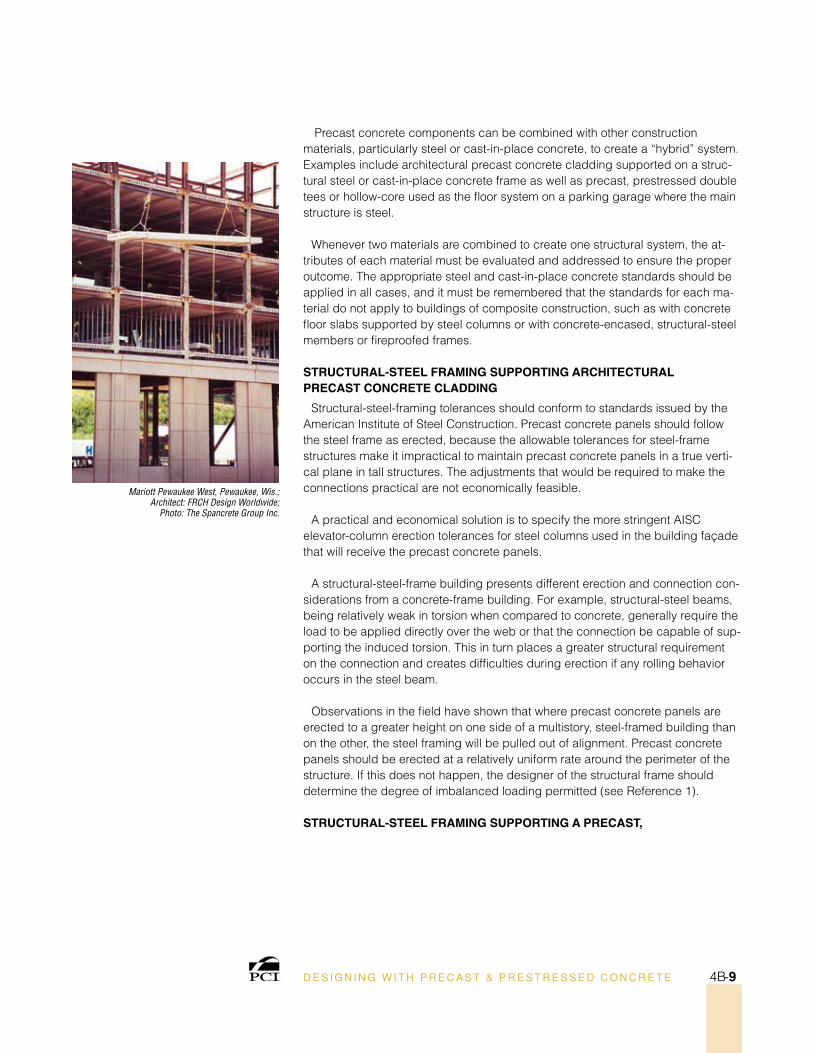
Mariott Pewaukee West, Pewaukee, Wis.; Architect: FRCH Design Worldwide;
Photo: The Spancrete Group Inc.
D E S I G N I N G W I T H P R E C A S T & P R E S T R E S S E D C O N C R E T E 4B-9
Precast concrete components can be combined with other construction materials, particularly steel or cast-in-place concrete, to create a “hybrid” system. Examples include architectural precast concrete cladding supported on a struc-tural steel or cast-in-place concrete frame as well as precast, prestressed double tees or hollow-core used as the floor system on a parking garage where the main structure is steel.
Whenever two materials are combined to create one structural system, the at-tributes of each material must be evaluated and addressed to ensure the proper outcome. The appropriate steel and cast-in-place concrete standards should be applied in all cases, and it must be remembered that the standards for each ma-terial do not apply to buildings of composite construction, such as with concrete floor slabs supported by steel columns or with concrete-encased, structural-steel members or fireproofed frames.
sTruCTurAl-sTeel FrAMing suPPorTing ArChiTeCTurAl PreCAsT ConCreTe ClADDing
Structural-steel-framing tolerances should conform to standards issued by the American Institute of Steel Construction. Precast concrete panels should follow the steel frame as erected, because the allowable tolerances for steel-frame structures make it impractical to maintain precast concrete panels in a true verti-cal plane in tall structures. The adjustments that would be required to make the connections practical are not economically feasible.
A practical and economical solution is to specify the more stringent AISC elevator-column erection tolerances for steel columns used in the building façade that will receive the precast concrete panels.
A structural-steel-frame building presents different erection and connection con-siderations from a concrete-frame building. For example, structural-steel beams, being relatively weak in torsion when compared to concrete, generally require the load to be applied directly over the web or that the connection be capable of sup-porting the induced torsion. This in turn places a greater structural requirement on the connection and creates difficulties during erection if any rolling behavior occurs in the steel beam.
Observations in the field have shown that where precast concrete panels are erected to a greater height on one side of a multistory, steel-framed building than on the other, the steel framing will be pulled out of alignment. Precast concrete panels should be erected at a relatively uniform rate around the perimeter of the structure. If this does not happen, the designer of the structural frame should determine the degree of imbalanced loading permitted (see Reference 1).
sTruCTurAl-sTeel FrAMing suPPorTing A PreCAsT,
ResouRces:MNL-120-04: PCI Design Handbook, Sixth Edition.PCI MNL-122-07: Architectural Precast Concrete, Third Edition.
1. Chapter 4, Section 4.6.3, “Erection Tolerances: Structural Steel Framing,” PCI MNL-122-07: Architectural Precast Concrete, Third Edition.
2. Chapter 4, Section 4.6.3, “Erection Tolerances: Cast-In-Place Concrete Frame,” PCI MNL-122-07: Architectural Precast Concrete, Third Edition.
RefeRences:
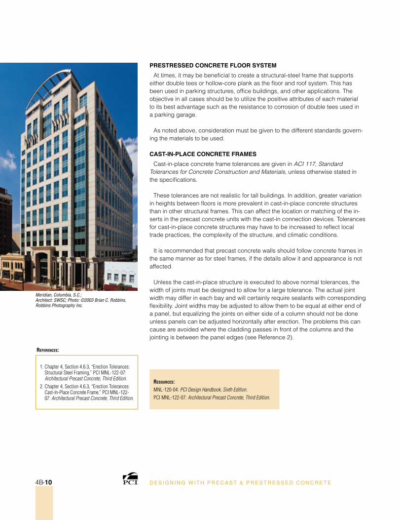
Meridian, Columbia, S.C.; Architect: SWSC; Photo: ©2003 Brian C. Robbins, Robbins Photography Inc.
D E S I G N I N G W I T H P R E C A S T & P R E S T R E S S E D C O N C R E T E4B-10
PresTresseD ConCreTe Floor sysTeM
At times, it may be beneficial to create a structural-steel frame that supports either double tees or hollow-core plank as the floor and roof system. This has been used in parking structures, office buildings, and other applications. The objective in all cases should be to utilize the positive attributes of each material to its best advantage such as the resistance to corrosion of double tees used in a parking garage.
As noted above, consideration must be given to the different standards govern-ing the materials to be used.
CAsT-in-PlACe ConCreTe FrAMes
Cast-in-place concrete frame tolerances are given in ACI 117, Standard Tolerances for Concrete Construction and Materials, unless otherwise stated in the specifications.
These tolerances are not realistic for tall buildings. In addition, greater variation in heights between floors is more prevalent in cast-in-place concrete structures than in other structural frames. This can affect the location or matching of the in-serts in the precast concrete units with the cast-in connection devices. Tolerances for cast-in-place concrete structures may have to be increased to reflect local trade practices, the complexity of the structure, and climatic conditions.
It is recommended that precast concrete walls should follow concrete frames in the same manner as for steel frames, if the details allow it and appearance is not affected.
Unless the cast-in-place structure is executed to above normal tolerances, the width of joints must be designed to allow for a large tolerance. The actual joint width may differ in each bay and will certainly require sealants with corresponding flexibility. Joint widths may be adjusted to allow them to be equal at either end of a panel, but equalizing the joints on either side of a column should not be done unless panels can be adjusted horizontally after erection. The problems this can cause are avoided where the cladding passes in front of the columns and the jointing is between the panel edges (see Reference 2).
D E S I G N I N G W I T H P R E C A S T & P R E S T R E S S E D C O N C R E T E 4B-11
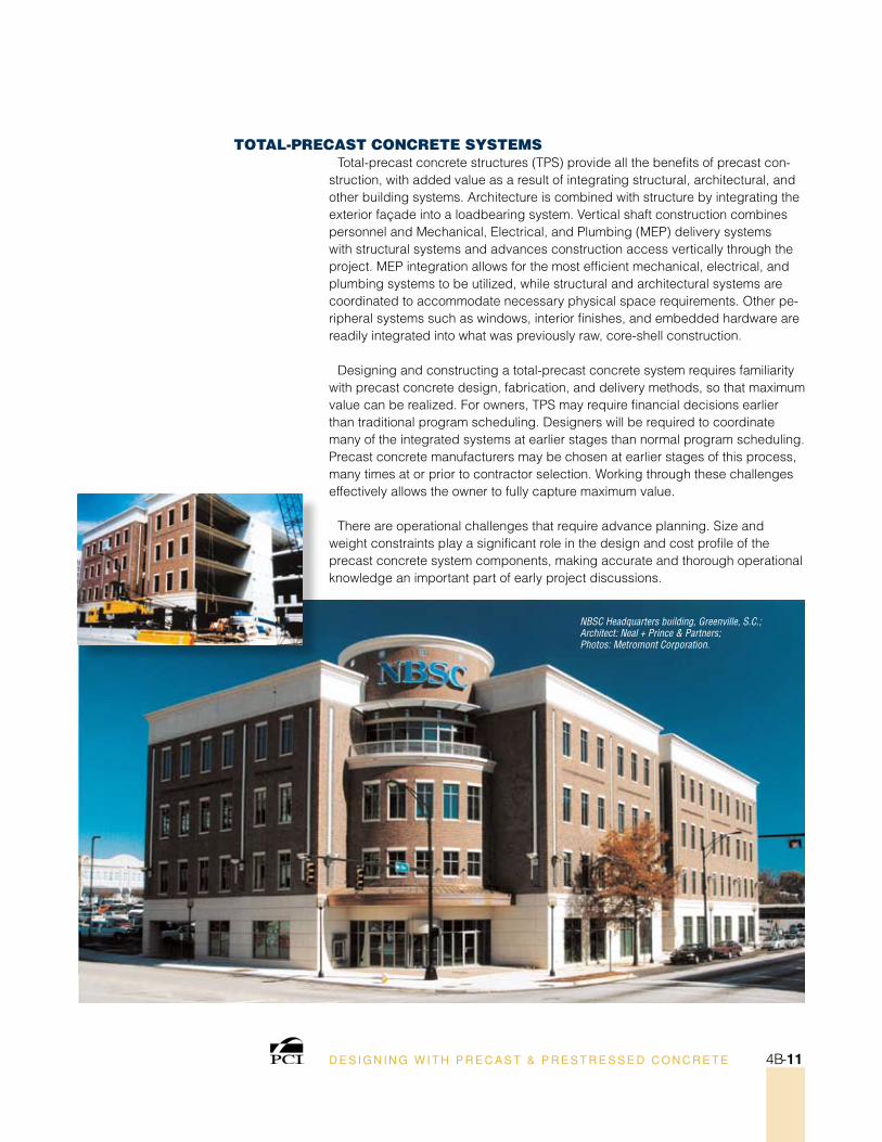
ToTal-PreCasT ConCreTe sysTemsTotal-precast concrete structures (TPS) provide all the benefits of precast con-
struction, with added value as a result of integrating structural, architectural, and other building systems. Architecture is combined with structure by integrating the exterior façade into a loadbearing system. Vertical shaft construction combines personnel and Mechanical, Electrical, and Plumbing (MEP) delivery systems with structural systems and advances construction access vertically through the project. MEP integration allows for the most efficient mechanical, electrical, and plumbing systems to be utilized, while structural and architectural systems are coordinated to accommodate necessary physical space requirements. Other pe-ripheral systems such as windows, interior finishes, and embedded hardware are readily integrated into what was previously raw, core-shell construction.
Designing and constructing a total-precast concrete system requires familiarity with precast concrete design, fabrication, and delivery methods, so that maximum value can be realized. For owners, TPS may require financial decisions earlier than traditional program scheduling. Designers will be required to coordinate many of the integrated systems at earlier stages than normal program scheduling. Precast concrete manufacturers may be chosen at earlier stages of this process, many times at or prior to contractor selection. Working through these challenges effectively allows the owner to fully capture maximum value.
There are operational challenges that require advance planning. Size and weight constraints play a significant role in the design and cost profile of the precast concrete system components, making accurate and thorough operational knowledge an important part of early project discussions.
NBSC Headquarters building, Greenville, S.C.;Architect: Neal + Prince & Partners; Photos: Metromont Corporation.
D E S I G N I N G W I T H P R E C A S T & P R E S T R E S S E D C O N C R E T E4B-12
scheduling
Owners should be encouraged to expedite procurement of the required precast concrete knowledge and expertise, usually through a qualified producer who can supply the project needs. This can be accomplished either through design-build procurement or direct negotiation with a precast concrete supplier.
Traditionally, a design team might move through the schematic design (SD)/design development (DD) phase of a project and into construction documents (CD), without intensive consideration of system integration. With TPS, this integra-tion begins shortly after the SD phase, if not immediately at the onset of design schematics. With proper planning and the inclusion of experienced design professionals, this process flows smoothly. Effort normally allotted to the CD and construction administration (CA) phases of a project are significantly shifted to the SD and DD phases, as functional systems and finishes are integrated into the basic core/shell design. This allows both the contracting group and design team to operate more effectively once construction commences, as the major core/shell coordination is substantially complete and emanating from a sole source, the precast concrete manufacturer/erector. Contractors and designers spend less ef-fort coordinating conflicts and more time with forward planning of site and interior finishes.
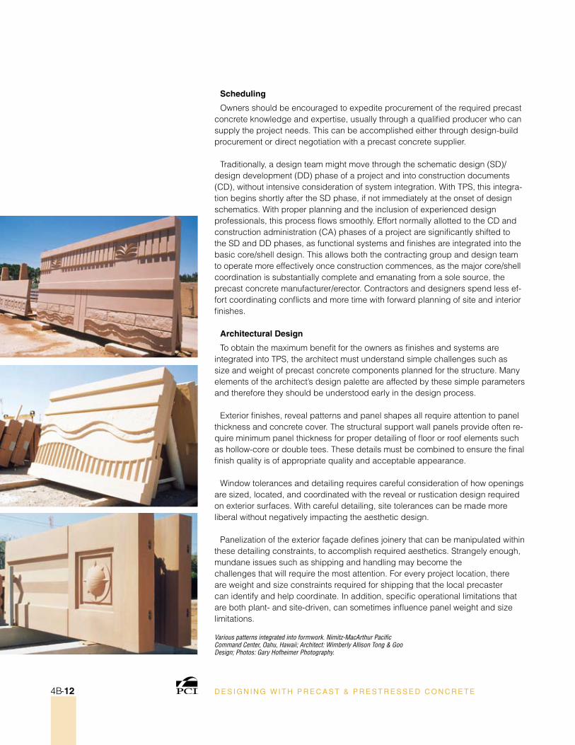
Architectural Design
To obtain the maximum benefit for the owners as finishes and systems are integrated into TPS, the architect must understand simple challenges such as size and weight of precast concrete components planned for the structure. Many elements of the architect’s design palette are affected by these simple parameters and therefore they should be understood early in the design process.
Exterior finishes, reveal patterns and panel shapes all require attention to panel thickness and concrete cover. The structural support wall panels provide often re-quire minimum panel thickness for proper detailing of floor or roof elements such as hollow-core or double tees. These details must be combined to ensure the final finish quality is of appropriate quality and acceptable appearance.
Window tolerances and detailing requires careful consideration of how openings are sized, located, and coordinated with the reveal or rustication design required on exterior surfaces. With careful detailing, site tolerances can be made more liberal without negatively impacting the aesthetic design.
Panelization of the exterior façade defines joinery that can be manipulated within these detailing constraints, to accomplish required aesthetics. Strangely enough, mundane issues such as shipping and handling may become the challenges that will require the most attention. For every project location, there are weight and size constraints required for shipping that the local precaster can identify and help coordinate. In addition, specific operational limitations that are both plant- and site-driven, can sometimes influence panel weight and size limitations.
Various patterns integrated into formwork. Nimitz-MacArthur Pacific Command Center, Oahu, Hawaii; Architect: Wimberly Allison Tong & Goo Design; Photos: Gary Hofheimer Photography.
D E S I G N I N G W I T H P R E C A S T & P R E S T R E S S E D C O N C R E T E 4B-13
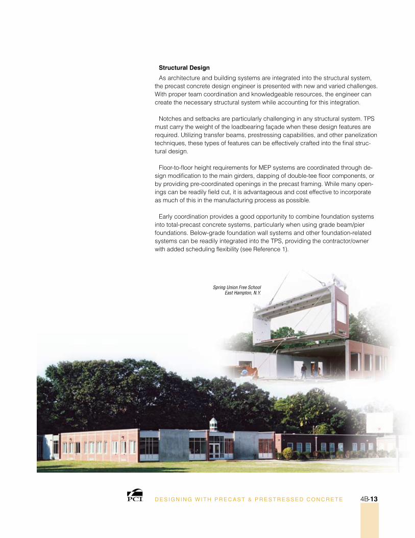
structural Design
As architecture and building systems are integrated into the structural system, the precast concrete design engineer is presented with new and varied challenges. With proper team coordination and knowledgeable resources, the engineer can create the necessary structural system while accounting for this integration.
Notches and setbacks are particularly challenging in any structural system. TPS must carry the weight of the loadbearing façade when these design features are required. Utilizing transfer beams, prestressing capabilities, and other panelization techniques, these types of features can be effectively crafted into the final struc-tural design.
Floor-to-floor height requirements for MEP systems are coordinated through de-sign modification to the main girders, dapping of double-tee floor components, or by providing pre-coordinated openings in the precast framing. While many open-ings can be readily field cut, it is advantageous and cost effective to incorporate as much of this in the manufacturing process as possible.
Early coordination provides a good opportunity to combine foundation systems into total-precast concrete systems, particularly when using grade beam/pier foundations. Below-grade foundation wall systems and other foundation-related systems can be readily integrated into the TPS, providing the contractor/owner with added scheduling flexibility (see Reference 1).
Spring Union Free School East Hampton, N.Y.
ResouRces:asCent: “All-Precast Concrete Residences Benefits Developers, Homeowners,” Ascent, Summer 2002, pp. 28-30.“All-Precast Design Garners Rave Reviews For Starz Encore,” Ascent, Winter 2003, pp. 16-22.“All-Precast Parking Structure Creates Attractive Solution,” Ascent, Winter 2005, pp. 20-28.“Auto Dealerships Sold on Precast Concrete Structures,” Ascent, Spring 2004, pp. 20-24.“Bookends, Special Awards,” Ascent, Fall 2005, p. 22.“Hopi Health Care Center, Building Awards,” Ascent, Fall 2001, pp. 48-49.“Lake Erie College of Osteopathic Medicine, Special Awards,” Ascent, Fall 2005, p. 24.“Precast Helps Car Dealer Create ‘3-D’ Showroom,” Ascent, Spring 2003, pp. 28-30.“The Shops at Willow Bend Parking Structures, Building Awards,” Ascent, Fall 2001, pp. 46-47.“Stacking Precast Office, Parking Saves Space,” Ascent, Summer 2002, pp. 24-26.“Team Perspective On Total-Precast Structures,” Ascent, Fall 2003, pp. 10-14.“Total Precast Concrete Offers Multiple Benefits,” Ascent, Spring 2005, pp. 24-26,“Total Precast Parking Features Brick Blend,” Ascent, Summer 2005, pp. 18-20.“Total Precast Systems’ Basic Building Blocks,” Ascent, Summer 2005, pp. 22-25.“Universities Exploit Precast For Mixed-Use Projects,” Ascent, Summer 2004, pp. 24-27. “University of Georgia Carlton Street Parking Structure, Special Awards,” Ascent, Fall 2002, p. 10.
PCI Journal:“All-Precast Concrete Design Delivers On-Time Opening for Florida’s LECOM Medical Students,” PCI Journal, January-February 2006, pp. 82-97.“All-Precast Concrete Design for the Saratoga Street Parking & Office Structure for the University of Maryland,” PCI Journal, March-April 2004, pp. 34-47.“All-Precast Concrete School of Architecture Creates Striking Identity for Florida International University,” PCI Journal, July-August 2004, pp. 58-71.“Aurora Municipal Center’s Stunning Design Showcases the Possibilities of Precast Concrete Solutions,” PCI Journal, November-December 2004, pp. 80-93.“Deerwood North Building 300, Jacksonville, Fla.,” PCI Journal, September-October 2004, pp. 136-139.“Energy Park Corporate Center, St. Paul, Minnesota,” PCI Journal, March-April 2005, pp. 136-141.“Hopi Health Center—An All-Precast Concrete Hospital in the Desert,” PCI Journal, July-August 2001, pp. 44-55.“Precast Parking Structures Enhance the Shops at Willow Bend,” PCI Journal, September-October 2001, pp. 36-45.“UGA’s Carlton Street Parking Facility Meets University Demands for Construction Speed and Aesthetics,” PCI Journal, November-December 2002, pp. 26-47.
1. “Total Precast Systems’ Basic Building Blocks,” Ascent, Summer 2005, pp. 22-25.
RefeRences:
D E S I G N I N G W I T H P R E C A S T & P R E S T R E S S E D C O N C R E T E4B-14
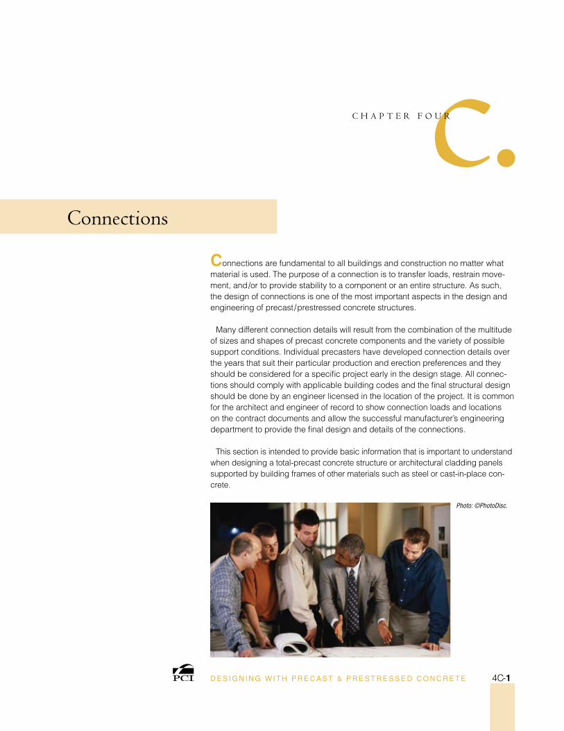
Photo: ©PhotoDisc.
D E S I G N I N G W I T H P R E C A S T & P R E S T R E S S E D C O N C R E T E 4C-1
c•C H A P T E R F O U R
Connections
Connections are fundamental to all buildings and construction no matter what material is used. The purpose of a connection is to transfer loads, restrain move-ment, and/or to provide stability to a component or an entire structure. As such, the design of connections is one of the most important aspects in the design and engineering of precast/prestressed concrete structures.
Many different connection details will result from the combination of the multitude of sizes and shapes of precast concrete components and the variety of possible support conditions. Individual precasters have developed connection details over the years that suit their particular production and erection preferences and they should be considered for a specific project early in the design stage. All connec-tions should comply with applicable building codes and the final structural design should be done by an engineer licensed in the location of the project. It is common for the architect and engineer of record to show connection loads and locations on the contract documents and allow the successful manufacturer’s engineering department to provide the final design and details of the connections.
This section is intended to provide basic information that is important to understand when designing a total-precast concrete structure or architectural cladding panels supported by building frames of other materials such as steel or cast-in-place con-crete.
D E S I G N I N G W I T H P R E C A S T & P R E S T R E S S E D C O N C R E T E4C-2
DesIgn ConsIDeraTIon
Precast concrete connections must meet a variety of design and performance criteria and not all connections are required to meet the same criteria. The basic criteria include:
strength A connection must have the strength to avoid failure during its lifetime.
Ductility This is the ability of a connection to undergo relatively large deforma-tions without failure. Ductility is achieved by designing the connection so that steel devices used yield before a weld or the concrete around the connection.
Volume Change Accommodation Restraint of movement due to creep, shrink-age, and temperature change can cause large stresses in precast concrete components and their connections. It is better to design the connection to allow some movement, which will relieve the build-up of these stresses.
Durability When the connection is exposed to weather or used in a corrosive environment, steel elements should be adequately covered by concrete, painted, epoxy-coated, or galvanized. Stainless steel may also be used, however, the added cost should be considered carefully.
Fire resistance Connections, which could jeopardize the structure’s stability if weakened by high temperatures from a fire, should be protected to the same degree as the components that they connect.
Constructability The following reflects only some of the items that should be considered when designing connections:
• Standardize connection types
• Avoid reinforcement and hardware congestion
• Avoid penetration of forms
• Reduce post-stripping work
• Consider clearances and tolerances of connection materials
• Avoid non-standard product and erection tolerances
• Plan for the shortest-possible crane hook-up time
• Provide for field adjustments
• Provide accessibility
• Determine if special inspection is required per the applicable code for the material and the welding process
• Provide as direct a load path as possible for the transfer of the load
Aesthetics For connections that are exposed to view in the final structure, the designer should incorporate a visually pleasing final product.
seismic requirements Structures and/or components that must be designed for seismic loads may require special consideration. Consultation with a structural engineer with experience in seismic design is recommended.
Tolerances The designer must realize that normal allowable fabrication, erection, and interfacing tolerances preclude the possibility of a perfect fit in the field.
D E S I G N I N G W I T H P R E C A S T & P R E S T R E S S E D C O N C R E T E 4C-3
ConneCTIon maTerIals
A wide variety of connection hardware and devices is used in the precast concrete industry including:
headed Concrete Anchors (studs) are round bars with an integral head. These are typically welded to plates to provide anchorage to the plate.
steel shapes including wide flanges, structural tubes, channels, plates, and angles.
reinforcing Bars are typically welded to steel sections to provide anchorage to the steel.
reinforcing Bar Couplers are typically proprietary devices for connecting reinforcing bars at a joint. Manufacturers of these devices can provide technical information.
Deformed Bar Anchors are similar in configuration to deformed reinforcing bars and are welded to steel shapes to provide anchorage similar to headed concrete anchors.
Bolts and Threaded Connectors are used in many precast concrete connections. Use of ASTM A36 or A307 bolts is typical. Use of high-strength ASTM A325 and A490 is usually not required.
specialty inserts are available from many manufacturers of these devices. They include standard threaded inserts, coil threaded inserts, and slotted inserts that provide for tolerances and field adjustment.
Bearing Pads are used predominantly for structural applications to support beams, double tees, and similar components. Use of random fiber oriented bearing pads (ROF) is recommended.
shims can be hard plastic or steel and are often used to provide adjustment to align a precast concrete component for elevation or horizontal alignment.
For the proper use and design of these and other materials reference the PCI Design Handbook 6th Edition (MNL 120-04) or the PCI Connections Manual (MNL 138-08).
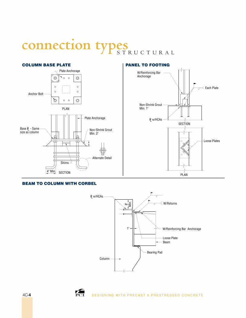
Plate Anchorage
Anchor Bolt
Non-Shrink Grout Min. 2"
Plate Anchorage
Alternate DetailShims
4" Min. SECTION
PLAN
Column Base PlaTe
Base PL - Same size as column
W/Reinforcing Bar Anchorage
Each Plate
Non-Shrink Grout Min. 1"
Loose Plates
SECTION
PLAN
PL w/HCAs
1"
Column
Bearing Pad
Beam
Panel To FooTIng
Beam To Column wITH CorBel
Loose Plate
W/Reinforcing Bar Anchorage
PL w/HCAs
W/Returns8" Min
.
D E S I G N I N G W I T H P R E C A S T & P R E S T R E S S E D C O N C R E T E4C-4
S T R U C T U R A Lconnection types
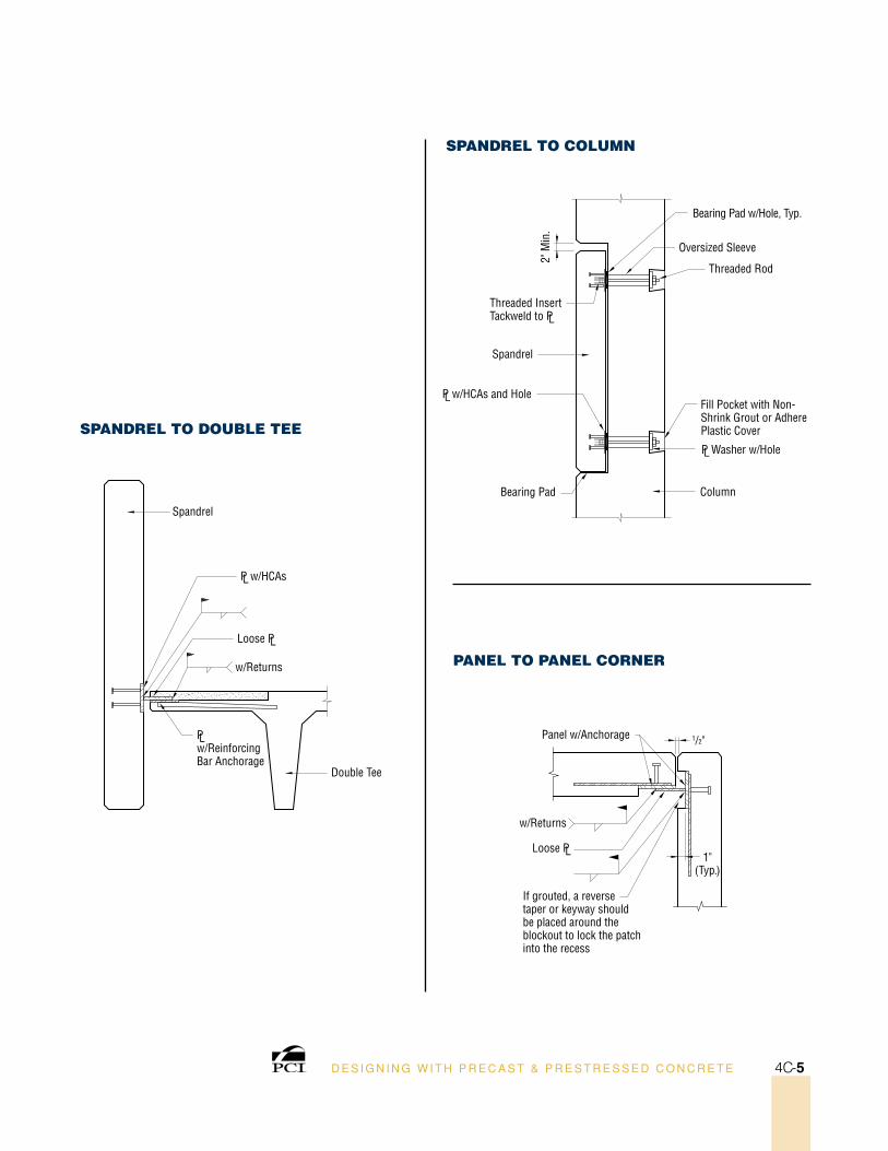
sPanDrel To DouBle Tee
sPanDrel To Column
Panel To Panel Corner
PL Washer w/Hole
Threaded Rod
Bearing Pad
Fill Pocket with Non-Shrink Grout or Adhere Plastic Cover
Column
Spandrel
2" M
in.
Threaded Insert Tackweld to PL
Bearing Pad w/Hole, Typ.
Oversized Sleeve
PL w/HCAs and Hole
PL w/Reinforcing Bar Anchorage
Double Tee
Spandrel
Loose PL
PL w/HCAs
w/Returns
1" (Typ.)
If grouted, a reverse taper or keyway should be placed around the blockout to lock the patch into the recess
Panel w/Anchorage 1/2"
w/Returns
Loose PL
D E S I G N I N G W I T H P R E C A S T & P R E S T R E S S E D C O N C R E T E 4C-5
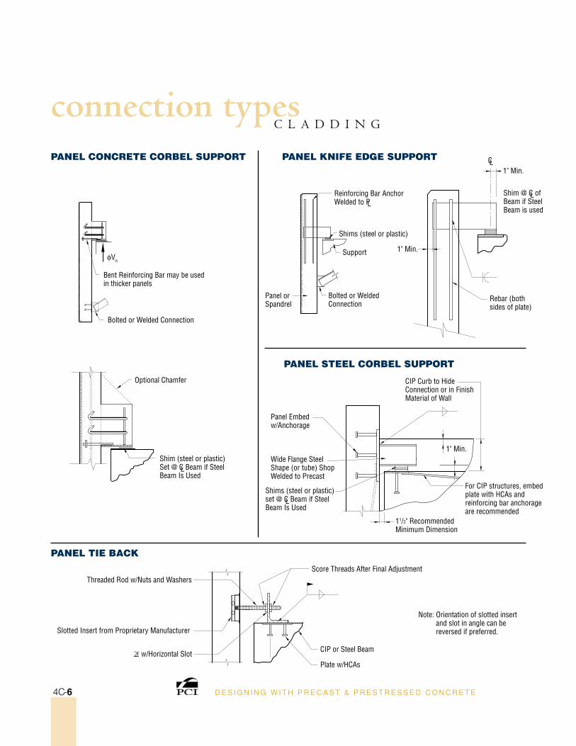
Shim @ CL of Beam if Steel Beam is used
Panel or Spandrel
Support
Rebar (both sides of plate)
Panel ConCreTe CorBel suPPorT
Panel TIe BaCk
Panel sTeel CorBel suPPorT
Panel knIFe eDge suPPorT1" Min.
CL
Reinforcing Bar Anchor Welded to PL
Shims (steel or plastic)
1" Min.
Bolted or Welded Connection
CIP Curb to Hide Connection or in Finish Material of Wall
For CIP structures, embed plate with HCAs and reinforcing bar anchorage are recommended
11/2" Recommended Minimum Dimension
Panel Embed w/Anchorage
Wide Flange Steel Shape (or tube) Shop Welded to Precast
Shims (steel or plastic) set @ CL Beam if Steel Beam Is Used
1" Min.Shim (steel or plastic) Set @ CL Beam if Steel Beam Is Used
Bent Reinforcing Bar may be used in thicker panels
Bolted or Welded Connection
φVn
Optional Chamfer
Threaded Rod w/Nuts and Washers
Slotted Insert from Proprietary Manufacturer
CIP or Steel Beam
Plate w/HCAs
Note: Orientation of slotted insert and slot in angle can be reversed if preferred.
Score Threads After Final Adjustment
∩
∠ w/Horizontal Slot
D E S I G N I N G W I T H P R E C A S T & P R E S T R E S S E D C O N C R E T E4C-6
C L A D D I N Gconnection types
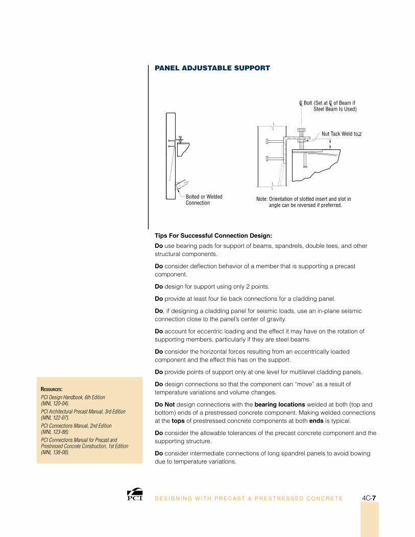
ResouRces:PCI Design Handbook, 6th Edition (MNL 120-04).PCI Architectural Precast Manual, 3rd Edition (MNL 122-07).PCI Connections Manual, 2nd Edition (MNL 123-88).PCI Connections Manual for Precast and Prestressed Concrete Construction, 1st Edition (MNL 138-08).
Panel aDjusTaBle suPPorT
CL Bolt (Set at CL of Beam if Steel Beam Is Used)
Bolted or Welded Connection
Note: Orientation of slotted insert and slot in angle can be reversed if preferred.
∩
∠Nut Tack Weld to
D E S I G N I N G W I T H P R E C A S T & P R E S T R E S S E D C O N C R E T E 4C-7
Tips For successful Connection Design:
Do use bearing pads for support of beams, spandrels, double tees, and other structural components.
Do consider deflection behavior of a member that is supporting a precast component.
Do design for support using only 2 points.
Do provide at least four tie back connections for a cladding panel.
Do, if designing a cladding panel for seismic loads, use an in-plane seismic connection close to the panel’s center of gravity.
Do account for eccentric loading and the effect it may have on the rotation of supporting members, particularly if they are steel beams.
Do consider the horizontal forces resulting from an eccentrically loaded component and the effect this has on the support.
Do provide points of support only at one level for multilevel cladding panels.
Do design connections so that the component can “move” as a result of temperature variations and volume changes.
Do not design connections with the bearing locations welded at both (top and bottom) ends of a prestressed concrete component. Making welded connections at the tops of prestressed concrete components at both ends is typical.
Do consider the allowable tolerances of the precast concrete component and the supporting structure.
Do consider intermediate connections of long spandrel panels to avoid bowing due to temperature variations.