Embed Size (px)
Citation preview
bull 201
207
12
Thank you for purchasing our MLCDPlease read through this users manual for safety before installing this product
This product is manufactured for Multi LCD model only
Userrsquos ManualOLM-4610 | OLM-4650 | OLM-4651
OLM-5510 | OLM-5550
Infinitely Expandable MLCDA revolutionary MLCD
A revolutionary MLCD
Infinitely Expandable MLCD
Address 257-6 Gongdan-dong Gumi-si Gyeongsangbuk-do KoreaTel +82-2-6678-8533 Fax +82-2-6678-8599
ORION COLTDwwworiondisplaynet
- 1 -
Infinitely Expandable Features of MLCD
Enjoy a wide flat screen with high brightness and high qualityEasy to install and move due to its thin designEnjoy your favorite programs with various split-screen features simultaneously presenting
several programs
To prevent electric shock Do not remove coverNo user serviceable part insideRefer servicing to qualified service personal
Warning
Thank you for purchasing our MLCD monitorThis manual describes how to use the product and notes in usePlease read the manual carefully before using itAfter reading this manual please retain for future reference If you have any questions or a problem occurs please contact either the company you purchased this product from or an authorized service center
Displaying static picture for an extended period of time may cause an burn-in effectBurn-in effect and the faults in brightness and picture elements caused by fixed images are not subject
to the warranty coverage
If you fail to comply with the regulations for safety and proper use fire or injury may be caused Warning
UsersManual GuidePin(4pcs) RS-232CCableDVI-DCable PowerCable
Supplied Accessories
Multi-ScreenControlSystem(MSCS)
Notice to usersClass A digital deviceIt is a device designed for business purpose with a safety certificate for electromagnetic interference which user should be mindful of
Important Safety Instructions
1) Read these instructions
2) Keep these instructions
3) Heed all warnings
4) Follow all instructions
5) Do not use this apparatus near water
6) Clean only with dry cloth
7) Do not block any ventilation openings Install in accordance with the manufacturerrsquos instructions
8) Do not install near any heat sources such as radiators heat registers stoves or other apparatus (including amplifiers) that produce heat
9) Do not defeat the safety purpose of the polarized or grounding-type plug A polarized plug has two blades with one wider than the other A grounding type plug has two blades and a third grounding prong The wide blade or the third prong are provided for your safety If the provided plug does not fit into your outlet consult an electrician for replacement of the obsolete outlet
10) Protect the power cord from being walked on or pinched particularly at plugs convenience receptacles and the point where they exit from the apparatus
11) Only use attachmentsaccessories specified by the manufacturer
12) Use only with the cart stand tripod bracket or table specified by the manufacturer or sold with the apparatus When a cart is used use caution when moving the cartapparatus combination to avoid injury from tip-over
13) Unplug this apparatus during lightning storms or when unused for long periods of time
14) Refer all servicing to qualified service personnel Servicing is required when the apparatus has been damaged in any way such as power-supply cord or plug is damaged liquid has been spilled or objects have fallen into the apparatus the apparatus has been exposed to rain or moisture does not operate normally or has been dropped The symbol in figure 21 shall be shown adjacent to the text of item 12 above
Optional AccessoriesMAIN FRAME(refer to page 14~15)
DVI Converter(ODC-10000)
REMOTE CONTROL
ON OFF
INFO
A
SET
DVIC1 DVIC2 INFO AUTO
VIDEO S-VIDEO HDSDI
DVI PC DTV HDMI
B
BROADCAST
ID SETTIN
G
ON
OFF
1 2 3
4 5 6
7 8
0
9DVI 1
DVI 2
OUTPUT FUNCTION
DVI CONVERTER INPUT
New MFC SET
MLCD
- 2 - - 3 -
ORION Infinitely Expandable
Contents
Cautions for consisting MLCD System 4Clearance for Ventilation6Do not cover the vent hole for the fan7Cleaning and Maintenance7 Please keep following instruction for panel protection without exception8Handle with Caution9How to carry MLCD10Application information111 Safety Precautions122 How to Install143 Guidance for Users164 How to Connect Cables18
41 Connection of Single MLCD18
42 Connection of Multiple MLCD20
43 Connection of Control Cable - In case of using MSCS22
44 Connection of Control Cable - In case of using the other control program besides MSCS24
45 Connection of DVI cable26
46 Connention of optional accessory27
47 ID setting of X x Y MLCD28
5 Setting and operation of MSCS software2951 MSCS Installation29
52 Start MSCS30
53 Setting of COM Port31
54 Setting of LAN Port (In case of connecting to a LAN Hub)32
55 Setting of LAN Port (In case of connecting directly to users computer)34
56 Network IP setting for MSCS 36
57 New designLast design setting37
58 Multi-screen configuration38
59 Selecting the command transmission method39
510 Changing the input source 40
511 Slide Control43
512 Picture Control46
513 Timer Control47
514 Tracking Control 48
515 ORION Homepage log on and Version Information49
6 Control Method of optional accessory5061 New MFC 50
62 DVI Converter 53
7 MSCS Protocol61Attachment ASCII to HEX Conversion Table77
8 Before calling for service789 Applicable signals (DVI PC)7910 Specification8011 Option Specification82
111 DVI Converter82
112 New MFC83
NOTICE
1 To disconnect the apparatus from the mains the plug must be pulled out from the mains socket therefore the mains plug shall be readily operable
2 WARNING - To Reduce The Risk Of Fire Or Electric Shock Do Not Expose This Appliance To Rain Or Moisture
3 Apparatus shall not be exposed to dripping or splashing and no objects filled with liquids such as vases shall be placed on the apparatus
4 Use only a properly grounded plug and receptacle
5 Warning CAUTION ndash These servicing instructions are for use by qualified service personnel only To reduce the risk of electric shock do not perform any servicing other than that contained in the operating instructions unless you are qualified to do so
6 Warning CAUTION ndash These servicing instructions are for use by qualified service personnel only To reduce the risk of electric shock do not perform any servicing other than that contained in the operating instructions unless you are qualified to do so
RISK OF ELECTRIC SHOCKDO NOT OPEN
CAUTION
CAUTION TO REDUCE THE RISK OF ELECTRIC SHOCKDO NOT REMOVE COVER (OR BACK)
NO USER-SERVICEABLE PARTS INSIDEREFER SERVICING TO QUALIFIED SERVICE PERSONNEL
This symbol is intended to alert the user to the presence of uninsulated dangerous voltage within the products enclosure that may be of sufficient magnitude to constitute a risk of electric shock to persons
This symbol is intended to alert the user to the presence of important operating and maintenance(servicing) instructions in the literature accompanying the appliance
MLCD
Environmental condition for installation
- Since MLCD panel is very sensitive for physical impact installation requires considerable caution
- Minimum clearance(20cm) must be secured for smooth ventilation (See page 6 14~15)Installation must avoid air tight or near air tight places Improper ventilation causes malfunction and shortens product lifetime by rapid internal temperature rise If MLCD has to installed at the improper ventilation additional ventilation openings or fans must be provided to keep the internal temperature between 0 ~ 35˚C
- For ground of MLCD and application devices it should be connected as frame ground
- Considering MLCD Max power consumption check the main electric specification
Consideration for easier service
- When you design the exterior design for MLCD system consider easier disassembly for possible service occasion in the future
- The sliding Universal Unit of ORION is recommended for easier service
- If service people can step into the backside of MLCD system it can greatly reduce time and effort for service
- In case of higher locations consider the installation location and exterior design for easier service
Cautions for consisting MLCD System
The number of Daisy chain connection
- The image quality may vary depend on the quality of signal and cable condition
INPUT SOURCE Resolution Connection Remark
DVI 1600 x 1200 x 60Hz 6 sets HDCP Available
PC 1600 x 1200 x 60Hz 3 sets
Video NTSC PAL SECAM 6 sets
RS-232C 30 sets ORION Cable Only
- If you need to use more MLCD sets than indicated in the table using a DVI distributor is highly recommended
Caution for the other control program besides MLCD Control Program (MSCS)
- If you want to use automatic power onoff function that make MLCD turned onoff by connecting main power allow at least 20 seconds of Stand-by time before MLCD is turned on when you make control program
- If RS-232C communication signal or other image signal is applied to 9 or more sets simultaneously communicational error may occur (Power on amp Broadcast)
- 4 - - 5 -
ORION Infinitely Expandable
WARNING
WARNING
MLCD
- When you install MLCD make sure there is at least 20cm clearance for effective ventilation and do not seal off MLCD sets If MLCD sets are installed at the locations of bad ventilation the inner temperature can be raised rapidly and it can cause frequent malfunctions and rapid reduction of the product life
Ventilation space in front of MLCD must be furnished for heat dispersionIf the front space of MLCD has to be sealed there must be consideration for the heat dispersion in the rear side of MLCD
- Carefully install MLCD not to cover the fan air holes with any structural object If the holes are covered with anything the inner temperature can be raised rapidly and it can cause malfunctions
- Regularly clean off the vent holes in the back of MLCD sets If the vent holes and the fan air holes are clogged with dust it prevents the air flow inside of MLCD sets It can cause rapid increase of the inner temperature and may cause malfunctions Clean off the vent holes and the fan air holes with a vacuum cleaner regularly
Clearance for Ventilation Do not cover the vent hole for the fan
Cleaning and Maintenance
Installation structure
FAN STB PWR ONVIDEO
IN OUT
DVI-D
IN OUT
RS-232C
IN OUT
PC
IN OUT
LAN
SVC
ID SELECT
CO LTD Made in Korea
To prevent electric shock Do not remove coverNo user serviceable part inside Refer servicing to qualified service personal
RISK OF ELECTRIC SHOCK DO NOT OPEN
CAUTION
bull Model Name OLM-4610bull Voltage AC~100 - 240Vbull Current Max 3Abull Frequency 5060Hzbull Serial No
MLCD
FAN
Vacuum Cleaner
- 6 - - 7 -
ORION Infinitely Expandable
WARNING
WARNING
MLCD
- 8 - - 9 -
ORION Infinitely Expandable
WARNING
WARNING
PANEL PANEL PANELPANEL
CUSHION
PANEL
WarningWarning
Handle with Caution - ShockImpact on the sets sides will result in
internal circuit damages
- The edgebottom of the panel are fragile Use shock-absorbing pads or rugs for laying down the product
bullPlease do not stand LCD alone It may fall or slip off and Panel can be broken or damaged
bull IfyouneedtostandLCDyoumustusehandlesonthebackandleanovertheLCDtoavoidpaneltouchesgroundorfloor
bullPlease do not lean over the LCD It may damage the bottom part of the LCD
bullIf you need to lay down LCD as face down position please use shock-absorbing pads under the LCD
bullPlease do not lean over the LCD toward the edge part It may damage the edge part of the LCD
bullIf you need to lay down LCD as face up position please be cautious for falling objects on the surface of the LCD
Please keep following instruction for panel protection without exception
- This product can be damaged even with minor impact for its nature Please keep following instruction to carry or store the products
MLCD
- 10 - - 11 -
ORION Infinitely Expandable
WARNING
WARNING
How to carry MLCD Application information
It always needs two persons to carry or install MLCD
When you carry MLCD with up straight manner please hold handles on the back and bottom part of the panel together
Please be careful not to touch the bottom part of the panel when you put down the panel
Pleasedonottouchthepanelwithyourhand
When you carry MLCD with flatbed manner please hold handles on the back and lower part of the back
Please be careful not to touch the bottom part of the panel when you put down the panel
If static images are displayed on the screen for a long time it causes burn-in imagePlease keep the following instruction to optimize the lifetime and functions of the product
1 Operating condition - Temperature 20 plusmn 15˚C - Humidity 55 plusmn 20 - Display pattern moving picture or regular switchover display - Environmental condition Well ventilated place is recommended - Power off and screen saver Periodical power-off or screen saver is needed after long-term static
displayNote Moving picture or black pattern is strongly recommended for screen saver
2 Operating methods to minimize burn-in image due to long-term static information display
- Suitable operating time under 20 hours a day - Periodical display contents change from static image to moving picture - Periodical background color and character (image) color change
DEPARTURE
AringAElig
DEPARTURE
Flight No Time Gate Flight No Time Gate
UA 012 1120 A02 UA 012 1120 A02
KE 732 1210 K17 KE 732 1210 K17
AN 291 1245 F11 AN 291 1245 F11
- Change the images of little luminance difference between the background and characters periodicallyDEPARTURE
AEligDEPARTURE
AEligDEPARTURE
AEligDEPARTURE
Flight No Time Gate Flight No Time Gate Flight No Time Gate Flight No Time Gate
UA 012 1120 A02 UA 012 1120 A02 UA 012 1120 A02 UA 012 1120 A02
- It is not recommended to display the images of huge luminance difference between the background and characters or the images of grey tone
ARRIVAL
(X)
ARRIVAL
(X)
Flight No Time Gate Delay Flight No Time Embark Delay
AA 213 920 K11 On time AA 213 920 New York On time
OZ 621 1125 G21 10 min OZ 621 1125 Seoul 10 min
JA 032 1205 A19 On time JA 032 1205 Beijing On time
- Scroll the characters periodicallyDEPARTURE
AElig AElig
DEPARTURE
Flight No Time Gate Flight No Time Gate
UA 012 1120 A02 UA 012 1120 A02
KE 732 1210 K17 KE 732 1210 K17
AN 291 1245 F11 AN 291 1245 F11
(Whole Screen Scroll)
DEPARTUREDEPARTURE
Flight NoFlight No
TimeTime
GateGate
UA 012KE 732UA 012KE 732
11201240
A02K17
13401520
K17A02
UA 012KE 732
17031820
A02K17
MLCD
- 12 - - 13 -
ORION Infinitely Expandable
1 Safety Precautions
bull If it operates abnormally stop using it immediately
bull Please refer to a specialized construction company for installing stand or wall mount unit Otherwise damage or injury may be caused
bullAvoid any action to damage the power cord or power plug It may cause fire or electric shock
bullDo not alter (or disassemble) the product It may cause electric shock since high voltage is flowing inside
bull Do not place any liquid-containing container on it If the inside is wet it may cause electric shock or fire
bullDo not touch the device when lightning strikes
bullDo not pull out the power plug with a wet hand It may cause electric shock
bullDo not install the product where it may be exposed to direct sunlight or near any heating device It may shorten the products life span or cause failure
bull Do not put any foreign material into the product It may cause a failure or shorten the life span
bull Do not install in an unstable location It may cause injury
bullDo not exceed ratings of AC outlet or extension cords It may cause failure
bull Make sure the product is not covered with any object If the ventilation hole is blocked the inside temperature may rise to cause overheating resulting in fire
bullDo not poke the front screen with sharp material It may damage the screen and may cause malfunction of the product
bullDo not lean against the product or keep it leaned It may cause injury or failure
bull Do not put it at any place with much humidity dust oil smoke or steam It may cause failure
bull If you do not want to use the product for a long time keep the power plug unplugged to save electricity
bullThe socket-outlet should be installed near the equipment and be easily accessible
bullDo not put any heavy object on it It may cause failure
bullDo not pull out or hang down the connection cable It may damage the cord to cause fire or electric shock
bull Pull out the power plug by holding the plug Otherwise it may damage the power cord to cause fire or electric shock
bullDo not ride or step on the product It may cause breakage when fallen down
bullWhen moving it disconnect the connecting cable Otherwise it may damage the cable to cause fire or electric shock
bull Install the product on safe and flat surface
bullDo not put candles on the product If the liquid flows inside the product It may cause electric shock or fire
bullDonottouchproductrsquosfrontsurfacewithhand Otherwise the image quality can be lowered
MLCD
- 14 - - 15 -
ORION Infinitely Expandable
Install on a MAIN FRAME StandPleasesecureminimumclearanceasshowninthepictureforadequateventilationandtechnicalservice
MAIN FRAME Stand Unit (Option)
bull The set can be installed as shown below (For further information refer to the optional MAIN FRAME Installation and Setup Guide)
bull Please do not install our product at following locations to protect the product and prevent possible malfunction
- Places of vibration or shock LCD set may fall and damaged - Next or near to Sprinkler sensors The sensors may detect heat from a set and sprinkler can be activated - Around high voltage power lines Noise from the power line may affect screen images - Around heating apparatus LCD set may be overheated and damaged
GuidePin
Hanger
HangerBolt
LCD
MAINFRAME
MAIN FRAME Wall Mounting Unit (Option)
bull The set can be installed on the wall as shown below (For further information refer to the optional MAIN FRAME Installation and Setup Guide)
Mount on the MAIN FRAME wallPleasesecureminimumclearanceasshowninthepictureforadequateventilationandtechnicalservice
bull Please check the stability of wall If the wall is not strong enough reinforce the wall before installation
bull Please connect all the cables to proper ports in a set before installation
Hanger
HangerBolt
LCD
MAINFRAME
GuidePin
WALLBRACKET
20cm
20cm
20cm20cm
2 How to Install
20cm
20cm20cm
MLCD
- 16 - - 17 -
ORION Infinitely Expandable
3 Guidance for Users
InputOutput Terminals
FAN STB PWR ONVIDEO
IN OUT
DVI-D
IN OUT
RS-232C
IN OUT
PC
IN OUT
LAN
SVC
ID SELECT
CO LTD Made in Korea
To prevent electric shock Do not remove coverNo user serviceable part inside Refer servicing to qualified service personal
RISK OF ELECTRIC SHOCK DO NOT OPEN
CAUTION
bull Model Name OLM-4610bull Voltage AC~100 - 240Vbull Current Max 3Abull Frequency 5060Hzbull Serial No
MLCD
FAN STB PWR ONVIDEO
IN OUT
DVI-D
IN OUT
RS-232C
IN OUT
PC
IN OUT
LAN
SVC
ID SELECT
➊
➋
➌
➍
➎ ➏
➐
➑
1PC In OutAnalog RGB Signal D-sub 15pin
2VIDEOComposite Signal BNC Jack
3DVIDigital RGB Signal DVI Single Link 24Pin
4RS-232CMLCD Control Firmware Upgrade D-sub 9pin
5LAN Ethernet Control RJ45
6Service PortFor the exclusive use of service
7ID SwitchSet ID Switch
8AC InputAC 100V ~240V 5060Hz
FAN STB PWR ONVIDEO
IN OUT
DVI-D
IN OUT
RS-232C
IN OUT
PC
IN OUT
LAN
SVC
ID SELECT
CO LTD Made in Korea
To prevent electric shock Do not remove coverNo user serviceable part inside Refer servicing to qualified service personal
RISK OF ELECTRIC SHOCK DO NOT OPEN
CAUTION
bull Model Name OLM-4610bull Voltage AC~100 - 240Vbull Current Max 3Abull Frequency 5060Hzbull Serial No
MLCD
Set ID Switch Setting bull Example of ID Switch setting
- You can set ID with 3 rotary switches as shown in the following figure
When you set ID of MLCD set power cable must be disconnected If power cable is not disconnected during ID setting MLCD set may be operated with the previous ID and it may cause abnormal behavior
For stable operation wait for at least 10 seconds prior to use MLCD control program after the first AC power connection
The product shape may vary depending on the model
bull LED Indication
LED Indication Description0 1 2
3
45678
90 1 23
45678
9 0 1 23
45678
9
FAN STB PWR ON
No Power
0 1 23
45678
90 1 23
45678
9 0 1 23
45678
9
FAN STB PWR ON
Insert power cord(Stand-By state)
0 1 23
45678
90 1 23
45678
9 0 1 23
45678
9
FAN STB PWR ON
Power On By MSCSThe PWR ON LED blinks continually
0 1 23
45678
90 1 23
45678
9 0 1 23
45678
9
FAN STB PWR ON
Power Off by MSCS Program(System ready)
FAN Normal - LED Off Abnormal - LED On IF FAN LED is turned on please check FANs
ON OFF BLINKING
[MLCD ID 01]0 1 2
3
45678
90 1 23
45678
9 0 1 23
45678
9
[MLCD ID 15]
0 1 23
45678
9
100digit10digitsingledigit
100digit10digitsingledigit
MLCD
- 18 - - 19 -
ORION Infinitely Expandable
FAN STB PWR ON
VIDEO
IN OUT
DVI-D
IN OUT
RS-232C
IN OUT
PC
IN OUT
LAN
SVC
ID SELECT
4 How to Connect Cables bull Do not connectdisconnect cables while MLCD or other external equipments are turned on
bull First turn off the power all the attached equipment and make connections
bull Make sure the power cord is inserted properly into the power inlet to prevent unexpected pullout of the cord
41 Connection of Single MLCD
bull MLCD and PC should be connected a Com Port in a PC and RS-232C IN port in a MLCD is connected with supplied RS-232C cable
bull MLCD OnOff or Screen adjustment can be controlled by MSCS (Multi-Screen Control System)
bull ID setting on the backside of MLCD must be identical with the ID setting in MSCS to control MLCD with a PC
bull If you do not have Com Port you need to use an USB converter for RS-232C Depending on manufacturers or models converters may cause malfunction
PC
PC (MSCS) to control MLCD
RS-232C(Maximum15m)
DVIconnection(Maximum5m)
PCConnection(Maximum5m)
IfyouneedlongerconnectionpleaseuseDVIboostersorDVIfiber-opticcable
[MLCD ID 01]
bullIDswitchmustbesetasID1foronesetuse
FAN STB PWR ONVIDEO
IN OUT
DVI-D
IN OUT
RS-232C
IN OUT
PC
IN OUT
LAN
SVC
ID SELECT
CO LTD Made in Korea
To prevent electric shock Do not remove coverNo user serviceable part inside Refer servicing to qualified service personal
RISK OF ELECTRIC SHOCK DO NOT OPEN
CAUTION
bull Model Name OLM-4610bull Voltage AC~100 - 240Vbull Current Max 3Abull Frequency 5060Hzbull Serial No
MLCD
0 1 23
45678
90 1 23
45678
9 0 1 23
45678
9
VCR
Videoconnection(Maximum5m)
MLCD
- 20 - - 21 -
ORION Infinitely Expandable
FAN STB PWR ON
VIDEO
IN OUT
DVI-D
IN OUT
RS-232C
IN OUT
PC
IN OUT
LAN
SVC
ID SELECT
FAN STB PWR ON
VIDEO
IN OUT
DVI-D
IN OUT
RS-232C
IN OUT
PC
IN OUT
LAN
SVC
ID SELECT
FAN STB PWR ON
VIDEO
IN OUT
DVI-D
IN OUT
RS-232C
IN OUT
PC
IN OUT
LAN
SVC
ID SELECT
FAN STB PWR ON
VIDEO
IN OUT
DVI-D
IN OUT
RS-232C
IN OUT
PC
IN OUT
LAN
SVC
ID SELECT
FAN STB PWR ON
VIDEO
IN OUT
DVI-D
IN OUT
RS-232C
IN OUT
PC
IN OUT
LAN
SVC
ID SELECT
42 Connection of Multiple MLCD
RS-232C
PC
VCR
PC
Video
DVI
MLCD 1 MLCD 2
bull Recommended maximum set connection for Multi setting is shown in table below If you need to connect more than described in the table you have to use distributors
bull Image quality can be affected by cable or signal quality
INPUT SOURCE Resolution Connection Remark
DVI 1600 x 1200 x 60Hz 6 sets HDCP Available
PC 1600 x 1200 x 60Hz 3 sets
Video NTSC PAL SECAM 6 sets
RS-232C 30 sets ORION Cable Only
PC (MSCS) to controlMLCD
MLCD 3 MLCD 4 MLCD 5
MLCD
- 22 - - 23 -
ORION Infinitely Expandable
43 Connection of Control Cable - In case of using MSCS
bull Control signal transmission can be connected by 2 different methods (RS-232C or Ethernet)
bull RS-232C and Ethernet connection cannot be used simultaneously
431 Connection of RS-232C Cable bull Maximum use of RS-232C with Daisy Chain connection is 30 sets or less if you need additional connection use RS-232C distributor
432 Connection of Ethernet Cable bull In case of Ethernet connection the control PC should be connected to one of MLCD sets with Ethernet cable For the connection between the MLCD sets they should be connected with RS-232C cables
ID 1
ID 7
ID 2
ID 5ID 4
ID 8
ID 3
ID 6
ID 9
RS-232C
IN OUT
RS-232C
IN OUT
RS-232C
IN OUT
RS-232C
IN OUT
RS-232C
IN OUT
RS-232C
IN OUT
RS-232C
IN OUT
RS-232C
IN OUT
RS-232C
IN OUT
RS-232C control PC
RS-232C
ID 1
ID 7
ID 2
ID 5ID 4
ID 8
ID 3
ID 6
ID 9
RS-232C
IN OUT
RS-232C
IN OUT
RS-232C
IN OUT
RS-232C
IN OUT
RS-232C
IN OUT
RS-232C
IN OUT
RS-232C
IN OUT
RS-232C
IN OUT
RS-232C
IN OUT
LAN
LAN
LAN
LAN
LAN
LAN
LAN
LAN
LAN
Ethernet control PC
HUB or Router(Wireless amp Cable)
LAN Cable(Direct Cable)
LAN Cable (Direct Cable)
LAN Cable (Cross Cable)
MLCD
- 24 - - 25 -
ORION Infinitely Expandable
44 Connection of Control Cable - In case of using the other control program besides MSCS
If you use the other screen control program besides MSCS the signal cable must be connected via MFC (Multi- Function Controller) of ORION
bull Control signal transmission can be connected by 2 different methods (RS-232C or Ethernet)
bull RS-232C and Ethernet connection cannot be used simultaneously
441 Connection of RS-232C Cable bull The RS-232C signal cable must be connected via MFC
bull Maximum use of RS-232C with Daisy Chain connection is 30 sets or less if you need additional connection use RS-232C distributor
442 Connection of Ethernet Cable bull If you want to control MLCD sets with Ethernet PC and MFC can be connected with Ethernet cable and between MFC and the first MLCD set and between the other MLCD sets should be connected with RS-232C cable
ID 1
ID 7
ID 2
ID 5ID 4
ID 8
ID 3
ID 6
ID 9
RS-232C
IN OUT
RS-232C
IN OUT
RS-232C
IN OUT
RS-232C
IN OUT
RS-232C
IN OUT
RS-232C
IN OUT
RS-232C
IN OUT
RS-232C
IN OUT
RS-232C
IN OUT
RS-232C control PC
RS-232C
New MFC
ID 1
ID 7
ID 2
ID 5ID 4
ID 8
ID 3
ID 6
ID 9
RS-232C
IN OUT
RS-232C
IN OUT
RS-232C
IN OUT
RS-232C
IN OUT
RS-232C
IN OUT
RS-232C
IN OUT
RS-232C
IN OUT
RS-232C
IN OUT
RS-232C
IN OUT
LAN
LAN
LAN
LAN
LAN
LAN
LAN
LAN
LAN
Ethernet control PC
New MFC
RS-232C
HUB or Router(Wireless amp Cable)
LAN Cable (Direct Cable)
LAN Cable (Cross Cable)
MLCD
- 26 - - 27 -
ORION Infinitely Expandable
ID 1
ID 7
ID 2
ID 5ID 4
ID 8
ID 3
ID 6
ID 9
DVI-D
IN OUT
DVI-D
IN OUT
DVI-D
IN OUT
DVI-D
IN OUT
DVI-D
IN OUT
DVI-D
IN OUT
DVI-D
IN OUT
DVI-D
IN OUT
DVI-D
IN OUT
RS-232C
IN OUT
RS-232C
IN OUT
RS-232C
IN OUT
RS-232C
IN OUT
RS-232C
IN OUT
RS-232C
IN OUT
RS-232C
IN OUT
RS-232C
IN OUT
RS-232C
IN OUT
45 Connection of DVI cable
RS-232C control PCDVI
DVI Signal Distributor(UXGA UP TO 165MHz)
Caution for DVI Distributor
If you want to display HDCP (High-bandwidth Digital Content Protection) applied contents you must use the distributor that supports HDCP function
46 Connention of optional accessory
ID 1
ID 4
ID 7
ID 2
ID 5
ID 8
ID 3
ID 6
ID 9
DVI-D
IN OUT
DVI-D
IN OUT
DVI-D
IN OUT
DVI-D
IN OUT
DVI-D
IN OUT
DVI-D
IN OUT
DVI-D
IN OUT
DVI-D
IN OUT
DVI-D
IN OUT
RS-232C
IN OUT
RS-232C
IN OUT
RS-232C
IN OUT
RS-232C
IN OUT
RS-232C
IN OUT
RS-232C
IN OUT
RS-232C
IN OUT
RS-232C
IN OUT
RS-232C
IN OUT
Video Source Control System
New MFCDVI Converter
RS-232C RS-485 USB Ethernet
CVBSS-VideoComponentPCHD-SDIHDMIDVI
DVI Signal Distributor
MLCD
- 28 - - 29 -
ORION Infinitely Expandable
47 ID setting of X x Y MLCD
bull Identity number (ID) indicates the location of each MLCD
bull When you look at the MLCD screens in front of MLCD
Recommended ID of X x Y screens
ID 1 ID 2 ID 3 ID 4 ID 5
ID 6 ID 7 ID 8 ID 9 ID 10
ID 11 ID 12 ID 13 ID 14 ID 15
ID 16 ID 17 ID 18 ID 19 ID 20
ID 21 ID 22 ID 23 ID 24 ID 25
0 1 23
45678
90 1 23
45678
9 0 1 23
45678
9 0 1 23
45678
90 1 23
45678
9 0 1 23
45678
9 0 1 23
45678
90 1 23
45678
9 0 1 23
45678
9 0 1 23
45678
90 1 23
45678
9 0 1 23
45678
9 0 1 23
45678
90 1 23
45678
9 0 1 23
45678
9
0 1 23
45678
90 1 23
45678
9 0 1 23
45678
9 0 1 23
45678
90 1 23
45678
9 0 1 23
45678
9 0 1 23
45678
90 1 23
45678
9 0 1 23
45678
9 0 1 23
45678
90 1 23
45678
9 0 1 23
45678
9 0 1 23
45678
90 1 23
45678
9 0 1 23
45678
9
0 1 23
45678
90 1 23
45678
9 0 1 23
45678
9 0 1 23
45678
90 1 23
45678
9 0 1 23
45678
9 0 1 23
45678
90 1 23
45678
9 0 1 23
45678
9 0 1 23
45678
90 1 23
45678
9 0 1 23
45678
9 0 1 23
45678
90 1 23
45678
9 0 1 23
45678
9
0 1 23
45678
90 1 23
45678
9 0 1 23
45678
9 0 1 23
45678
90 1 23
45678
9 0 1 23
45678
9 0 1 23
45678
90 1 23
45678
9 0 1 23
45678
9 0 1 23
45678
90 1 23
45678
9 0 1 23
45678
9 0 1 23
45678
90 1 23
45678
9 0 1 23
45678
9
0 1 23
45678
90 1 23
45678
9 0 1 23
45678
9 0 1 23
45678
90 1 23
45678
9 0 1 23
45678
9 0 1 23
45678
90 1 23
45678
9 0 1 23
45678
9 0 1 23
45678
90 1 23
45678
9 0 1 23
45678
9 0 1 23
45678
90 1 23
45678
9 0 1 23
45678
9
LCD ID1
LCD ID2
LCD ID3
LCD ID4
LCD ID5
LCD ID6
LCD ID7
LCD ID8
LCD ID9
LCD ID10
LCD ID11
LCD ID12
LCD ID13
LCD ID14
LCD ID15
LCD ID16
LCD ID17
LCD ID18
LCD ID19
LCD ID20
LCD ID21
LCD ID22
LCD ID23
LCD ID24
LCD ID25
[MLCD ID 01]0 1 2
3
45678
90 1 23
45678
9 0 1 23
45678
9
100digit10digitsingledigit
5 Setting and operation of MSCS software
51 MSCS Installation
bull Insert the Installation CD
bull You can see following installation start screen
bull Select proper version for your product and start installation
bull MSCS supports Windowsreg 2000 Windowsreg XP and Windowsreg Vista Windowsreg 7trade only
MSCS Installation start screen
Caution for using MSCS
1 Data for Picture control Manual Tracking and so forth can be read by clicking the right button of your mouse on the desired MLCD set from MSCS Please do not use above function together with the other functions
2 When you off AC power execute power off by MSCS first and disconnect AC power to save your configuration
Caution
MSCS Versions can be changed for function improvement without prior notice
MLCD
- 30 - - 31 -
ORION Infinitely Expandable
52 Start MSCS
bull MSCS is an application program needed to control MLCD
bull When you execute MSCS (v 70) for your product at the installation screen it will create a new folder at CProgram FileMSCS (v70) and an icon on your computer screen
bull By double clicking the MSCS (v 70) icon the initial screen image of MSCS (v 70) will be displayed as shown in the picture
Main Image of MSCS (Multi Screen Control system)
53 Setting of COM Port
bull Com Port connects or disconnects the communication between PC and MLCD
bull Connect MLCD to PC Com Port via RS-232C cable
bull Go to MSCS Menu -gt Communication and set Com Port Click Connect using mouse or press Ctrl+C using keyboard
bull In order to disconnect communication click Disconnect using mouse or press Ctrl+D using keyboard
bull When you use USB-to-RS-232C converters you need to set Com Port again because MSCS uses one of Com Port no 1 to 30 Available Com Port on the PC is automatically recognized and displayed
bull Com Port Configuration
Baud Rate 115200bps(Fixed)
Data Bit 8Bits
Parity None
Stop Bit 1Bit
Flow Control None
MLCD
- 32 - - 33 -
ORION Infinitely Expandable
54 Setting of LAN Port (In case of connecting to a LAN Hub)
bull This function is used to control the MLCD via LAN PORT
During the setting process MLCD and control PC should be connected via RS-232C cable only Do not connect ethernet cable
After setting process the control PC should be connected to one of MLCD sets with Ethernet cable only For the connection between the MLCD sets they should be connected with RS-232C cables
n Network IP setting for MLCD1) Execute the LAN Configurator V10 from installation CD
2) Select Com Port and select OPEN
3) Select ID of MLCD which you want to control
4) Turn off MLCD
5) Type in IP Address
6) Click SET TCPIP Info
7) Click GET TCPIP Info and Confirm the IP Address
8) Close the LAN Configurator V10
MLCD
- 34 - - 35 -
ORION Infinitely Expandable
55 Setting of LAN Port (In case of connecting directly to users computer)
n Check the network informations1) Execute the LAN Configurator V10 from installation CD
2) Select Com Port and select OPEN
3) Select ID of MLCD which you want to control
4) Turn off MLCD
5) Click GET TCPIP Info and check the network informations
6) Input the network information of the userrsquos PC to be identical with MLCD set However the final digit of the IP address must be different
MLCD
- 36 - - 37 -
ORION Infinitely Expandable
56 Network IP setting for MSCS
1 Execute the MSCS
2 Select Menu-gtCommunication -gt Setup orCtrl+U to start setup
3 Select Socket radio button
4 Type in IP Address of MLCD
5 Click Ping Test to check status of communication
6 Close the Commnication setup window
bull Menu Description bull Serial Set the serial communication as a default communication
bull Com Port Set the port of a PC to communicate with MLCD
bull Baud Rate Fixed at 115200bps
Caution Users cannot change the Baud rate
bull Socket Set the Ethernet LAN communication
bull Edit Box Set the IP address
bull Port Number Fixed as 9761
Caution Users cannot change the port number
bull Ping Test Test the IP address
bull Connect Connect the communication
Communication Setup
57 New designLast design setting
bull You can see following pop-up window for New designLast design when you click Connect or press Ctrl+C using keyboard after select communication type
NewLast Design Set
bull Click Open New Design to prepare new configuration
bull Click Open Last Design to go to last design before closing
bull When the connection is successfully completed after setting Com Port following Message dialog is displayed The dialog window will be disappeared in 1 second
bull When the connection is successfully completed after setting Lan Port following Message dialog is displayed The dialog window will be disappeared in 1 second
MLCD
- 38 - - 39 -
ORION Infinitely Expandable
58 Multi-screen configuration
1 Input the numbers of X and Y
- X is for the number of row and Y is for column - X and Y can be selected within the range from 1 to 15 The maximum MLCD quantity of MSCS
control is 100 sets - MLCD image of selected numbers of X and Y is displayed in the Screen configuration in one second
after setting the number
Screen Configuration Setting
2 Select one of input sources from DVI PC or Video
3 Execution of the configuration
- When you click PLAYbutton after selecting input source from Source select and the numbers of X and Y in MLCD Configuration the configuration of MLCD is generated as shown in the figure below
INFO - Check the resolution of the input source It is displayed at the upper right corner of the screen - Check the signal If there is no input signal No signal is displayed
DVI
DVI
DVI
DVI
DVI
DVI
DVI
DVI
DVI
59 Selecting the command transmission method
bull ONE LCD Transmit Protocol Command to one MLCD
bull ALL LCD Transmit the Protocol command sequentially to all connected MLCD sets
bull Broadcast Transmit the Protocol command simultaneously to all connected MLCD sets
bull In order to control power of specific MLCD use Power OnOff button after selecting the specific MLCD
MLCD Control - Power OnOff
bull Please wait for at least 10 seconds before executing Power On command after the first AC power connection If not it may cause abnormal behavior
bull Please disconnect AC power and reconnect in case of abnormal behaviorCaution
MLCD
- 40 - - 41 -
ORION Infinitely Expandable
510 Changing the input source
bull Varieties of screen formations are available with screen configuration
bull Select DVI PC or Video at the Input Select menu
1) If you select DVI and click Play button at the Input Select menu the input source will be changed from PC to DVI - In case you do not select a screen and click Play the input source for the all screen will be changed
Select DVI at the Input Select menu
Input source is not displayed on the MSCS screen but it is indicated by colors (DVI Yellow PC Green Video Gray)
2) Screen formation bull To make various Input-screen formation select an input source and click the screen you want in the Screen configuration with the left button of the mouse
1 Select PC at the Input Select menu
- eg) in case PC is selected
2 Click the screen you want in the Screen configuration with the left button of the mouse
- Click the screen you want in the Screen configuration with the left button of the mouse - DVI screen will be changed with PC
PC
DVI
DVI
DVI
PC
DVI
DVI
DVI
DVI
MLCD
- 42 - - 43 -
ORION Infinitely Expandable
3) Screen Formation with one step bull You can make various multi-screen formations with simple movement
1 Select an input source at Source Select menu
- eg) In case you want to select PC
2 Click the screen you want in the Screen Configuration with the left button of the mouse and drag
- Click the screen you want in the Screen Configuration with the left button of the mouse and drag to the screen you want to include
- When you stop dragging selected screens will be changed to PC automatically
DVI
DVI
DVI
DVI
DVI
DVI
DVI
DVI
DVI
PC
PC
DVI
PC
PC
DVI
DVI
DVI
DVI
511 Slide Control
bull MLCD configuration that users can choose is displayed repeatedly
bull To use Slide Control go to MSCS Menu -gt Control -gt Slide Control or press Ctrl+S using Keyboard
1 Make a desirable configuration in Screen Configurations
2 Set Operation Time in Slide Control
- Click Add button to save configuration - The range of Operation Time is from 10 seconds to 1 hour
DVI
DVI
DVI
DVI
DVI
DVI
DVI
DVI
DVI
DVI
DVI
DVI
DVI
DVI
DVI
DVI
DVI
DVI
MLCD
- 44 - - 45 -
ORION Infinitely Expandable
3 Save various screen configurations in the same way
4 Click Slide Start to display saved screen configurations
- Saved screen configurations are displaying for preset time
5 Check Repeat to display saved configuration repeatedly
DVI
DVI
DVI
PC
PC
PC
PC
PC
PC
PC
PC
DVI
PC
PC
DVI
DVI
DVI
DVI
6 Click Stop button to end Slide Control
7 Save or Load the slide configuration
- Click SAVE button to save user added Slide configuration as ssd file - Click LOAD button to open saved ssd file
To view the saved screen configuration select the list from List Box
Saved screen protocol is transmitted to MLCD by double clicking the list
bull When you load Slide File previous slide configuration and new slide configuration must be identical
bull If they are different the file cannot be loaded So revise the new slide file configuration as previous configuration or save as new file
Caution
MLCD
- 46 - - 47 -
ORION Infinitely Expandable
512 Picture Control
bull Register values related to display of MLCD can be changed
bull To use Picture Control go to MSCS Menu -gt Control -gt Picture Control or press Ctrl+P using Keyboard
bull In order to control display values input values directly in Edit Box and press Enter key Or click -+ button using mouse
bull Click Exit button or press Ctrl+X using keyboard to close Picture Control window
bull Color Temp Change the color temperature of the screen -Normal Initial setting Proper for normal video image view -Studio Low Color temperature Proper for broadcasting purpose
bull Brightness The range of Brightness you can adjust is 0 to 100
bull Contrast The range of Contrast you can adjust is 0 to 100
bull Sharpness The range of Sharpness you can adjust is 0 to 28
bull Dimmong The range of ldquoDimmingrdquo you can adjust is 0 to 100
bull User Data Users can adjust color impression with white screen and save or load the adjusted value - Save - Save Userrsquos data file (pdt) - Load - Load Userrsquos data file (pdt)
513 Timer Control
bull Users can decide the time of turning on or off MLCD set by timer control
bull To use this function click Menu -gt Control-gt Timer Control or use Ctrl +M keys from the keyboard
bull How to set the time of power on or off
a) Select Hour and Minutes of turn on or offb) After setting Power OnOff time click ldquoAddrdquo button to add it to Power OnOff List Box
You can save up to 10 settings for Power OnOff Also you can delete the saved settings in the List Box one by one with ldquoRemoverdquo button If you delete all the settings click ldquoRemove Allrdquo button
c) Select once for one time use and Daily for daily use then click Startd) Power on or off signal will be transmitted to MLCD at the time of user set
bull Time Dialog must be activated to use Timer function
Timer Control Dialog
MLCD
- 48 - - 49 -
ORION Infinitely Expandable
515 ORION Homepage log on and Version Information
bull In order to move to Orion website go to Help of menu bar -gtOrionDisplay HomePage
ORION Homepage Log on
bull Go to Help of menu bar -gt About to check MSCS
Checking MSCS Version
bull Go to Control in menu bar -gt Tracking Control or press Ctrl+T using keyboard to run Tracking window
bull Press Tracking Auto button in order to run auto tracking
bull In case alignment doesnt work through Tracking Auto command user can tune finely through Manual
bull Manual Tracking enables users to set Frequency Phase LineStart and PixelStart
bull Select panel ID which you want to adjust alignment
bull Detail adjustment steps are as follows
1) Tune Phase until the vertical lines are clearly adjusted
2) Tune LineStart to adjust vertical alignment PixelStart for horizontal alignment
3) Adjust Frequency if alignment is still wrong If you adjust Frequency repeat step 1) and 2) to fit alignment Adjustable range is as follows
-The range of Frequency you can adjust is -50 to 50
-The range of Phase you can adjust is 0 to 63
-The range of Linestart you can adjust is -23 to 10
-The range of Pixelstart you can adjust is -50 to 40
bull Click EXIT button or press Ctrl+X using keyboard to close Tracking window
When Tracking windows is on display users cannot display Picture Control window
Even when Tracking window is on display selecting panel ID is available by clicking right button of mouse
514 Tracking Control
bull Alignment adjustment is available when input source is PC
Tracking Manual Window
MLCD
- 50 - - 51 -
ORION Infinitely Expandable
NewMFCRear
AdaoterJack(5V1A)
MLCDConnect
PCConnectEthernetConnect
USBConnect
ASConnect
6 Control Method of optional accessory
61 New MFC
1) New MFC Connection1 Connect power
2 Connect female D-sub to the Com port in a computer
3 Connect male D-sub to the RS-232C port in MLCD
4 Install the MFC connected with RS-232C cable and a power adapter at the location of good Remote controller reception
5 Set the number of the connected MLCD units in advance The number can be set only by the Remote controller
Horizontal configuration
1 Press SET button
SET
2 Press Left and Right buttons sequentially to enter the horizontal configuration mode
INFO
3 When the 2 LEDs at lower right corner of each 7-segment of lower line in the New MFC are turned on the horizontal configuration mode is started
HOR
VER
HOR
VER
4 Use the number buttons to set the numbers of MLCD sets in horizontal
line
- eg If you want to set 5 for horizontal number press 0 for tens place and 5 for ones place
1 2 3
4 5 6
7 8
0
9
HOR
VER
5 Pres SET button to finish the horizontal configuration mode
SET
REMOTE CONTROL
ON OFF
INFO
A
SET
DVIC1 DVIC2 INFO AUTO
VIDEO S-VIDEO HDSDI
DVI PC DTV HDMI
B
BROADCAST
ID SETTIN
G
ON
OFF
1 2 3
4 5 6
7 8
0
9DVI 1
DVI 2
OUTPUT FUNCTION
DVI CONVERTER INPUT
2) MLCD Set Configuration (eg X5 sets x Y6 sets)
MLCDNxMConfiguration NewMFCFront
HOR
VER
MLCD
- 52 - - 53 -
ORION Infinitely Expandable
Vertical configuration
1 Press SET button
SET
2 Press Up and Down buttons sequentially to enter the vertical configuration mode
INFO
3 When the 2 LEDs at lower right corner of each 7-segment of lower line in the New MFC are turned on the vertical configuration mode is started
HOR
VER
HOR
VER
4 Use the number buttons to set the numbers of MLCD sets in horizontal line
- eg If you want to set 6 for vertical number press 0 for tens place and 6 for ones place
1 2 3
4 5 6
7 8
0
9
HOR
VER
5 Pres SET button to finish the vertical configuration mode
SET
REMOTE CONTROL
ON OFF
INFO
A
SET
DVIC1 DVIC2 INFO AUTO
VIDEO S-VIDEO HDSDI
DVI PC DTV HDMI
B
BROADCAST
ID SETTIN
G
ON
OFF
1 2 3
4 5 6
7 8
0
9DVI 1
DVI 2
OUTPUT FUNCTION
DVI CONVERTER INPUT
62 DVI Converter
bull To use DVI Converter go to MSCS Menu rarr Device rarr DVI Converter or press Ctrl+V using Keyboard
DVI Converter Dialog
MLCD
- 54 - - 55 -
ORION Infinitely Expandable
1) ID bull Set the ID of DVI Converter The ID can be selected from 1 to 9
2) CMND bull Select the channel of DVI converter to control
bull One of DVI Channel 1(DVIC1) DVI Channel 2(DVIC2) and ALL DVI Channel can be selected
3) Input Mode bull Select the input mode of DVI Converter
bull One of DVI HDMI HDSDI PC DTV S-VIDEO and VIDEO can be selected
bull Set Select one mode from 7 Input Modes and execute
4) Output Resolution bull Set the output resolution of DVI Converter
Resolution frequency
640 x 480 60Hz 85Hz
800 x 600 50Hz 60Hz 85Hz
853 x 480 50Hz 60Hz
1024 x 768 60Hz 85Hz
1280 x 1024 50Hz 60Hz
1600 x 900 50Hz 60Hz
1600 x 1200 50Hz 60Hz
1706 x 960 60Hz
1920 x 1080p 50Hz 60Hz
bull Set Set the output resolution
5) OSD Information bull The DVI converter input and input resolution are displayed on the screen
6) Aspect Ratio bull Set or change the screen ratio (Horizontal Vertical)
bull 16 9 Set the screen ratio as 169 wide screen
bull 4 3 Set the screen ratio as 43
bull LB(Letter Box) Expand the screen image to remove the black patterns at the top and bottom portions of the screen
bull LBS(Letter Box Subtitle) Expand the screen with the subtitle to the top portion (The bottom portion remains with black pattern)
MLCD
- 56 - - 57 -
ORION Infinitely Expandable
7) Key Lock Mode bull Lock the front key of DVI Converter not to turn On or Off
8) Status bull Display the DVI Converter status (Input Source Input Resolution Output Resolution Aspect Ratio PIP Mode Test Pattern Key Lock FreeRunLock Firmware Version MSCS Version information)
9) Picture Control bull Control the Brightness Contrast Sharpness Color and Tint of the DVI Converter
bull Brightness The range of Brightness you can adjust is 0 to 100
bull Contrast The range of Contrast you can adjust is 0 to 100
bull Sharpness The range of Sharpness you can adjust is 0 to 28
bull Color The range of Color you can adjust is 0 to 100
bull Tint The range of Tint you can adjust is 0 to 90
bull Firmware Default Initialize the adjusted values to the default values
MLCD
- 58 - - 59 -
ORION Infinitely Expandable
10) Pattern bull Select the Test Pattern (Red Blue 8-Color 16-Gray Green White White (10) Screen)
bull Set Set or change the Pattern
11) LockFreeRun bull Lock Default setting It is used when MLCD is configured as the default display
If the vertical frequency of input signal and out signal is identical output is generated according to vertical synchronization
bull FreeRun This function is used when the default display is not MLCD and screen image is not displayed It generates its own output vertical frequency regardless of input signal If screen image is displayed use Lock mode
bull LockFreeRun can be configured by the keypad of DVI converter besides MSCS While Menu OSD is not displayed FreeRun mode can be selected by pressing UP key and Lock mode by DOWN key
12) Tracking bull Control the Screen size sharpness and position of DVI Converter with PC input mode
bull In case alignment doesnt work through Tracking Auto command users can tune finely through Manual Tracking
bull Manual Tracking window enables users to set Frequency Phase LineStart and PixelStart
bull Detail adjustment steps are as follows
1) Tune Phase until the vertical lines are clearly adjusted
2) Tune LineStart to adjust vertical alignment PixelStart for horizontal alignment
3) Adjust Frequency if alignment is still wrong If you adjust Frequency repeat step 1) and 2) to fit alignment Adjustable range is as follows
bull Frequency The range of Frequency you can adjust is -50 to 50
bull Phase The range of Phase you can adjust is 0 to 63
bull Linestart The range of Linestart you can adjust is -23 to 10
bull Pixelstart The range of Pixelstart you can adjust is -50 to 40
bull Auto Tracking Automatic alignment for DVI Converter screens
bull Auto Calibration Automatic color control for DVI Converter screen
MLCD
- 60 - - 61 -
ORION Infinitely Expandable
13) PIP (Picture In Picture) bull A variety of images can be displayed with the PIP function of DVI converter To activate PIP click PIP in the Mode The position of sub-picture can be controlled by clicking - + buttons increase or decrease the number or directly type in the numbers at Edit box
bull Various input sources can be used To set the sub-input click the sub-input combo box and select sub-input
bull Main screen and sub-screen can be swapped with the PIP Swap function Press Set button at the right side of PIP Swap If you want to return to previous screen press Normal button at the right side of PIP Swap
bull Mode Normal mode - Normal screen without PIP (PIP Off) PIP mode-Sub-screen is displayed at the lower right corner of the screen (PIP On)
bull Position Horizontal - Adjust the horizontal location of PIP Adjustable range 0~100 Vertical - Adjust the vertical location of PIP Adjustable range 0~100
bull Sub Input Set the input for PIP One of DVI HDMI HDSDI PC DTV S-VIDEO and VIDEO can be selected for sub-input
According to the main input the sub-input can be restricted If the main input is a digital input such as DVI HDMI or HD-SDI the sub-input should be an analog input such as PC DTV S-VIDEO or Video If the main input is an analog input the sub-input should be a digital input
bull PIP Swap OFF - Return to previous locations of swapped Main Source Input screen and Sub Source Input screen ON - Exchange the locations of Main Source Input screen and Sub Source Input
screen
1 IntroductionThischaptercontainsthecommunicationprotocolbetweenLCDanditscontroldevicessuchascomputerforbetteruseoftheproductHoweveritdoesnotincludedetailedtechnicalmattersItratherfocusesonthebrieffunctionalexplanationandcommunicationprotocol
ID1
Master Master Master Master
Master Master Master Master
Master Master
Master Master
Controller(Computer)
TxRx Line ID2 IDN-1 IDN
IDN+1 IDN+N
ID(M-2)N+1 ID(M-2)N+N
ID(M-1)N ID(M-1)N+2 ID(M-1)N+N-1 IDMXN
TheconnectioncanbevariablebasedonenvironmentortheusersrsquointentionltCommunicationconnectiondiagramgt
11 Communication Setting
Transmission amp Reception type
Connection type Baudrate Data Bits Parity Stop Bits Flow Control
Asynchronous Serial Communication
Daisy Chain 115200 8 None 1 None
2ProtocolFormat
21 Send To LCD
STX Command Length Data ETX
1 byte 1 byte 1 byte Variable 1 byte
ID Master Other Data
1 byte 1 byte N byte
- ThisishowtosendcommandstoLCDOnlythesetofthedesignatedIDisworkingaccordingtotheCommandButiftheIDvalueis0allMLCDsetsareworkingaccordingtocommandasBroadcast- STX(0x02)TheinitialcodeItmeansthebeginningofProtocol(Fixedvalue)- CommandCodeforactualoperation(Variable)- LengththelengthofDataarea(Variable0~255)- DatatheareasforIDandtheotherData(Variable)- IDItisacodetodistinguishLCDsetsItsrangeis0to255IftheIDis0itmeansBroadcastcommand(variable)- Master(0x01)Thisisthescalercode- ETX(0x03)Theendofthecode(Fixedvalue)
7 MSCS Protocol
MLCD
- 62 - - 63 -
ORION Infinitely Expandable
22 Receive From LCD
STX CMD Length Data Check Sum ETX
1 byte 1 byte 1 byte Variable 1 byte 1 byte
ID Master Other Data
1 byte 1 byte N byte
- ResponsebyacertaincommandfromthedesignatedsetamongMLCDsetsThedifferencefromSendtoLCDisChecksum
- STX(0x02)TheinitialcodeItmeansthebeginningofProtocol(Fixedvalue)
- CommandCodeforactualoperation(Variable)
- LengththelengthofDataarea(Variable0~255)
- DatatheareasforIDandtheotherData(Variable)
- IDSetidentification(0~255)(Variable)
- Master(0x01)Thisisthescalercode
- ChecksumexecuteNotoperationafteraddingallthevaluesinSTX~Dataarea
- ETX(0x03)Theendofthecode(Fixedvalue))
- Communication SequenceWaitfor50msecforresponseaftersendingthecommandIfthereisnoresponseitisrecommendedtoresendthecommand
Itisrecommendedthatnotsendingtheothercommandorchanginginputresolutionduringcommandtransmission
Commandtransmission rarrlarr
Responsetransmission
3Command
31 Power On
- Command for Power On Operative status
- It is available only during Power Off(Stand-by) status
- CMD 0x40
- Send to MLCD
A Normalcommand
STX CMD LengthData
ETXID Master
Value 0x02 0x40 0x02 Variable 0x01 0x03
IDrange(Program)0x01(1)~0xFF(255)
B Broadcastcommand
STX CMD Length Data ID ETX
Value 0x02 0x40 0x01 0x00 0x03
MakeallLCDdothesameoperationButtherewillbenoreturncommunication(Onewaycommand)
- Receive from MLCD
STX CMD LengthData
Check Sum ETXID Master
Value 0x02 0x40 0x02 Variable 0x01 Variable 0x03
IDrange(Program)0x01(1)~0xFF(255)
ChecksumexecuteNotoperationafteraddingallthevaluesinSTX~Dataarea
32 Power Off
- Command for Power Off Stand-by status
- It is available only during Power On (Operative) status
- CMD 0x41
- Send to MLCD
A Normalcommand
STX CMD LengthData
ETXID Master
Value 0x02 0x41 0x02 Variable 0x01 0x03
IDrange(Program)0x01(1)~0xFF(255)
B Broadcastcommand
STX CMD Length Data ID ETX
Value 0x02 0x41 0x01 0x00 0x03
AllLCDwilldothesameoperationsimultaneouslyButtherewillbenoreturncommunication(Onewaycommand)
- Receive from MLCD
STX CMD LengthData
Check Sum ETXID Master
Value 0x02 0x41 0x02 Variable 0x01 Variable 0x03
IDrange(Program)0x01(1)~0xFF(255)
ChecksumexecuteNotoperationafteraddingallthevaluesinSTX~Dataarea
33 Multi-Scale
- Command for expanding the screen of MLCD
- It is available only on Power On (Operative) status
- CMD 0XDD (DVI) 0XDE(PC) 0XE2(VIDEO)
- Send to MLCD
A Normalcommand
STX CMD LengthData
ETXID Master XY P
Value 0x02 Variable 0x04 Variable 0x01 Variable Variable 0x03
IDrange(Program)0x01(1)~0xFF(255)
XYThenumberofhorizontalaxis(X)thenumberofverticalaxis(Y)upper4bits-X(Max15)Lower4bits-Y(Max15)
Pthelocationofexpandedscreen
B Broadcastcommand
STX CMD LengthData
ETXID XY S X
Value 0x02 Variable 0x04 0x00 Variable Variable Variable 0x03
ID0x00
XYThenumberofMLCDsetsinhorizontalline(X)thenumberofMLCDsetsinverticalline(Y)
Thetop4bits-X(Max15)thebottom4bits-Y(Max15)11screenratio(Fullscreen)isldquo0x11rdquo
STheIDofMLCDtobeexpandedintopleftposition11screenratio(Fullscreen)isldquo0x00rdquo
MLCD
- 64 - - 65 -
ORION Infinitely Expandable
XThenumberofallXaxisline11screenratio(Fullscreen)isldquo0x01rdquo
MakeallLCDdothesameoperationButtherewillbenoreturncommunication(Onewaycommand)
Broadcastcommandeg)Incaseof5x5MLCDformation
1 4
13 11
0x02(STX) 0xDD(CMD) 0x04(Length) 0x00(ID) 0x33(XY) 0x01(S) 0x05(X) 0x03(ETX)
0x02(STX) 0xDD(CMD) 0x04(Length) 0x00(ID) 0x33(XY) 0x0D(S) 0x05(X) 0x03(ETX)
0x02(STX) 0xDD(CMD) 0x04(Length) 0x00(ID) 0x22(XY) 0x04(S) 0x05(X) 0x03(ETX)
0x02(STX) 0xDD(CMD) 0x04(Length) 0x00(ID) 0x41(XY) 0x0B(S) 0x05(X) 0x03(ETX)
0x02(STX) 0xDD(CMD) 0x04(Length) 0x00(ID) 0x11(XY) 0x00(S) 0x01(X) 0x03(ETX)
- Receive from MLCD
STX CMD LengthData
Check Sum ETXID Master
Value 0x02 Variable 0x02 Variable 0x01 Variable 0x03
IDrange(Program)0x01(1)~0xFF(255)
CheckSumexecuteNotoperationafteraddingallthevaluesinSTX~Dataarea
34 Infomation
- Command for displaying the information on the screen (Input source and resolution by OSD)
- It is available only on Power On (Operative) status
- CMD 0x42
- Send to MLCD
A Normalcommand
STX CMD LengthData
ETXID Master
Value 0x02 0x42 0x02 Variable 0X01 0x03
IDrange(Program)0x01(1)~0xFF(255)
B Broadcastcommand
STX CMD Length Data ID ETX
Value 0x02 0x42 0x01 0x00 0x03
AllLCDwilldothesameoperationsimultaneouslyButtherewillbenoreturncommunication(Onewaycommand)
- Receive from MLCD
STX CMD LengthData
Check Sum ETXID Master
Value 0x02 0x40 0x02 Variable 0X01 Variable 0x03
IDrange(Program)0x01(1)~0xFF(255)
CheckSumexecuteNotoperationafteraddingallthevaluesinSTX~Dataarea
35 Input-Mode Change
- Command for changing input mode without screen scaling
- It is available only on Power On (Operative) status
- CMD 0xDD(DVI) 0XDE(PC) 0XE2(Video)
- Send to MLCDA NormalCommand
STX CMD LengthData
ETXID Master
Value 0x02 Variable 0x02 Variable 0X01 0x03
IDrange(Program)0x01(1)~0xFF(255)
B BroadcastCommand
STX CMD Length Data ID ETX
Value 0x02 Variable 0x01 0x00 0x03
MakeallLCD(MasterSlave)dothesameoperationButtherewillbenoreturncommunication(Onewaycommand)
- Receive from MLCD
STX CMD LengthData
Check Sum ETXID Master
Value 0x02 Variable 0x02 Variable 0X01 Variable 0x03
IDrange(Program)0x01(1)~0xFF(255)
CheckSumexecuteNotoperationafteraddingallthevaluesinSTX~Dataarea
36 Global Offset
- Command for removing the image data in seam area (On) or displaying all the data on the screen (Off)
- It is available only on Power On (Operative) status
- CMD 0x74(On) 0x73(Off)
- Send to MLCD
A NormalCommand
STX CMD LengthData
ETXID Master
Value 0x02 Variable 0x02 Variable 0X01 0x03
IDrange(Program)0x01(1)~0xFF(255)
B BroadcastCommand
STX CMD Length Data ID ETX
Value 0x02 Variable 0x01 0x00 0x03
MakeallLCD(MasterSlave)dothesameoperationButtherewillbenoreturncommunication(Onewaycommand)
- Receive from MLCD
STX CMD LengthData
Check Sum ETXID Master
Value 0x02 Variable 0x02 Variable 0X01 Variable 0x03
IDrange(Program)0x01(1)~0xFF(255)
CheckSumexecuteNotoperationafteraddingallthevaluesinSTX~Dataarea
MLCD
- 66 - - 67 -
ORION Infinitely Expandable
37 Auto-Power Mode
- Configuration for automatic power on by AC power connection
- It is available only on Power On (Operative) status
- CMD 0x62(On) 0x63(Off)
- Send to MLCD
A NormalCommand
STX CMD LengthData
ETXID Master
Value 0x02 Variable 0x02 Variable 0X01 0x03
IDrange(Program)0x01(1)~0xFF(255)
B BroadcastCommand
STX CMD Length Data ID ETX
Value 0x02 Variable 0x01 0x00 0x03
AllLCDwilldothesameoperationsimultaneouslyButtherewillbenoreturncommunication(Onewaycommand)
- Receive from MLCD
STX CMD LengthData
Check Sum ETXID Master
Value 0x02 Variable 0x02 Variable 0X01 Variable 0x03
IDrange(Program)0x01(1)~0xFF(255)
CheckSumexecuteNotoperationafteraddingallthevaluesinSTX~Dataarea
38 DTV Over-Scan OnOff
- Users can select Over-scan when input is DTV resolution from DVI It is only available with DVI mode
- It is usable only at Power on status
- CMD 0xE4(On) 0xE5(Off)
- Send to MLCD
A NormalCommand
STX CMD LengthData
ETXID Master
Value 0x02 Variable 0x02 Variable 0X01 0x03
IDrange(Program)0x01(1)~0xFF(255)
B BroadcastCommand
STX CMD Length Data ID ETX
Value 0x02 Variable 0x01 0x00 0x03
MakeallLCDdothesameoperationButtherewillbenoreturncommunication(Onewaycommand)
- Receive from MLCD
STX CMD LengthData
Check Sum ETXID Master
Value 0x02 Variable 0x02 Variable 0X01 Variable 0x03
IDrange(Program)0x01(1)~0xFF(255)
CheckSumExecuteNotoperationafteraddingallthevaluesinSTX~Dataarea
39 Over-Temperature Shut-down Control
- Commands for automatic power off making MLCD set stand-by and OSD warning method if IP board temperature is 95 or higher
- It is available only on Power On (Operative) status
- The initial configuration is Over Temperature Shut-down Enable
- CMD0x64(OverTemperatureShut-downEnable)
IncaseIPboardtemperatureis95orhigherdisplaywarningsignalHighTemperatureinredfor1minuteatthelowerleft
cornerofMLCDandpoweroffautomatically(Stand-bymode)
0x65(OverTemperatureShut-downDisable)
IncaseIPboardtemperatureis95orhigherdisplaywarningsignalHighTemperatureinredfor3secondsatthelowerleft
cornerofMLCDandrepeatthewarningevery60seconds(Noautomaticpoweroff)
- Send to MLCDA NormalCommand
STX CMD LengthData
ETXID Master
Value 0x02 Variable 0x02 Variable 0x01 0x03
IDrange(Program)0x01(1)~0xFF(255)
B BroadcastCommand
STX CMD Length Data ID ETX
Value 0x02 Variable 0x01 0x00 0x03
MakeallLCDdothesameoperationButtherewillbenoreturncommunication(Onewaycommand)
- Receive from MLCD
STX CMD LengthData
Check Sum ETXID Master
Value 0x02 Variable 0x02 Variable 0x01 Variable 0x03
IDrange(Program)0x01(1)~0xFF(255)
CheckSumAddthesumfromSTXtoDataandexecuteNotoperation
310 Test Pattern
- Command for checking the operating status with internal patterns
- It is available only on Power On (Operative) status
- CMD 0x57 (Red) 0x58 (Green) 0x59 (Blue) 0x5A (White) 0x5B (Screen)
- Send to MLCD
A NormalCommand
STX CMD LengthData
ETXID Master
Value 0x02 Variable 0x02 Variable 0X01 0x03
IDrange(Program)0x01(1)~0xFF(255)
B BroadcastCommand
STX CMD Length Data ID ETX
Value 0x02 Variable 0x01 0x00 0x03
MakeallLCDdothesameoperationButtherewillbenoreturncommunication(Onewaycommand)
MLCD
- 68 - - 69 -
ORION Infinitely Expandable
- Receive from MLCD
STX CMD LengthData
Check Sum ETXID Master
Value 0x02 Variable 0x02 Variable 0X01 Variable 0x03
IDrange(Program)0x01(1)~0xFF(255)
CheckSumexecuteNotoperationafteraddingallthevaluesinSTX~Dataarea
311 FAN Mode
- Command for FAN control
- It is available only on Power On (Operative) status
- CMD 0xD8
- Send to MLCD
A NormalCommand
STX CMD LengthData
ETXID Master Control
Value 0x02 0xD8 0x02 Variable 0x01 Variable 0x03
IDrange(Program)0x01(1)~0xFF(255)
ControlAuto(0x00)Full(0x01)
B BroadcastCommand
STX CMD LengthData
ETXID Control
Value 0x02 0xD8 0x02 0x00 Variable 0x03
Buttherewillbenoreturncommunication(Onewaycommand)
- Receive from MLCD
STX CMD LengthData
Check Sum ETXID Master
Value 0x02 0xD8 0x02 Variable 0x01 Variable 0x03
IDrange(Program)0x01(1)~0xFF(255)
CheckSumexecuteNotoperationafteraddingallthevaluesinSTX~Dataarea
312 Elapsed Time
- Command for informing the elapsed time of each LCD set (Basic unit hour)
- It is available only on Power On (Operative) status
- CMD 0x77 (Get) 0x7B (Initial)
- Send to MLCD
STX CMD LengthData
ETXID Master
Value 0x02 Variable 0x02 Variable 0X01 0x03
IDrange(Program)0x01(1)~0xFF(255)
ItisnotapplicableasBroad-castcommand
- Receive from MLCD
STX CMD LengthData Check
SumETX
ID Master Elapsed Time
Value 0x02 Variable 0x08 Variable 0X01 hellip Variable 0x03
Hundred thousands
ten thou-sands thousands hundreds ten one
Variable Variable Variable Variable Variable Variable
IDrange(Program)0x01(1)~0xFF(255)
CheckSumExecuteNotoperationafteraddingallthevaluesinSTX~Dataarea
ElapsedTime
-Hundredthousandstenthousandsthousandshundredstensones0(0x00)~9(0x09)rangevalue
313 IP Serial Number
- Command for assigning and identifying the serial numbers of each IP board (8 digit)
- CMD 0x75 (Get SN) 0x76 (Set SN)
- Send to MLCD
STX CMD LengthData
ETXID Master
Value 0x02 Variable 0x02 Variable 0X01 0x03
IDrange(Program)0x01(1)~0xFF(255)
GetSetIPSerialNumber(0x750x76)commandisnotapplicableasBroad-castcommandbecauseeachLCDshouldhavean
uniqueserialnumber
- Receive from MLCD
STX CMD LengthData Check
SumETX
ID Master SN
Value 0x02 Variable 0x0A Variable 0x01 hellip Variable 0x03
0 1st 2nd 3rd 4th 5th 6th 7th
Variable Variable Variable Variable Variable Variable Variable Variable
IDrange(Program)0x01(1)~0xFF(255)
CheckSumExecuteNotoperationafteraddingallthevaluesinSTX~Dataarea
ElapsedTime
-01st2nd3rd4th5th6th7th0(0x00)~9(0x09)rangevalue
314 Get Current Status
- Command for obtain the current LCD (IP) information
- It is available only on Power On (Operative) status
- CMD 0x87
- Send to MLCD
STX CMD LengthData
ETXID Master
Value 0x02 0x87 0x02 Variable 0X01 0x03
IDrange(Program)0x01(1)~0xFF(255)
ItcannotbeusedasBroad-castcommand
MLCD
- 70 - - 71 -
ORION Infinitely Expandable
- Receive from MLCD
STX CMD LengthData
Check Sum ETXID Master Status
Value 0x02 0x87 0x23 Variable 0X01 hellip Variable 0x03
IDrange(Program)0x01(1)~0xFF(255)
CheckSumExecuteNotoperationafteraddingallthevaluesinSTX~Dataarea
Status(32byte)
No Data Length Explanation
1 PWR Status 1 byte 0PowerOff(Stand-by)1PowerOn(Working)
2 Input Source 1 byte 0x0CPC0x0BDVI0x0DDTV0x07DVD0x05S-Video0x02Video
3 Resolution 1 byte ThevalueofDisplayedResolutionatthetimeofdetection
4 Not Used
5 Global Offset 1 byte 0GlobalOffsetOff1GlobalOffsetOn
6 Color Temp 1 byte 0Normalmode1Studiomode
7 Auto-Power Mode 1 byte 0Auto-PowerOff1Auto-PowerOn
8 FAN Mode 1 byte 0Auto1Full
9 Temperature0 1 byte0(0x00) 0˚C~ 127(0x7F) 127˚C 128(0x80) -1˚C ~ 254(0xFE) -127˚C0xFF Temp Sensor Error
10 Temperature1 1 byte0(0x00) 0˚C ~ 127(0x7F) 127˚C 128(0x80) -1˚C ~ 254(0xFE) -127˚C0xFF Temp Sensor Error
11 FAN Status 1 byte 0x30 Good 0x31 Error 0x32 Dont Care
12~18 FW Version 7 byteYear2byteMonth2byteDay2byteRev(0~9)1byteEx)December29th2012Rev2rarr0x010x020x010x020x020x090x02
19 Not Used
20~27 SN 8 byte123456 rarr0x000x000x010x020x030x040x050x061 rarr0x000x000x000x000x000x000x000x01
28~33 Elapsed Time 6 byte54321 rarr 0x00 0x05 0x04 0x03 0x02 0x0110 rarr 0x00 0x00 0x00 0x00 0x01 0x00
ltDisplayedResolutionatthetimeofdetection(ItisdifferentfromthesupportingResolution)gt
Resolution Value Resolution Value Resolution Value
640x480x60 0(0x00) 720Px50 29(0x1D) 1360x768x60 25(0x19)
640x480x85 1(0x01) 576Px50 30(0x1E) 640x350x85 46(0x2E)
800x600x56 2(0x02) 480Px60 31(0x1F) 640x480x75 47(0x2F)
800x600x60 3(0x03) 1920x1080ix60 32(0x20) 640x480x72 48(0x30)
800x600x75 4(0x04) 1920x1080ix50 33(0x21) 1152x864x75 49(0x31)
800x600x85 5(0x05) 1280x720Px60 34(0x22) 1280x720x60 50(0x32)
853x480x60 6(0x06) 1280x720Px50 35(0x23) 1280x768x75 51(0x33)
1024x768x60 7(0x07) PAL 36(0x24) 1280x1024x75 52(0x34)
1024x768x70 8(0x08) SECAM 37(0x25) 1366x768x50 53(0x35)
1024x768x75 9(0x09) PALP 38(0x26) 1400x1050x50 54(0x36)
1024x768x85 10(0x0A) NTSC 39(0x27) 1440x900x60 55(0x37)
1280x768x60 11(0x0B) NTSCP 40(0x28) 576ix50 56(0x38)
1280x960x60 12(0x0C) Unknown 42(0x2A) 480ix60 57(0x39)
1280x1024x60 13(0x0D) No-Signal 43(0x2B) 1080px60 58(0x3A)
1366x768x60 14(0x0E) 853x480x50 18(0x12) 1080px50 59(0x3B)
1600x1200x60 15(0x0F) 1280x1024x50 19(0x13) 1920x1080px60 60(0x3C)
1400x1050x60 16(0x10) 1360x768x50 20(0x14) 1920x1080px50 61(0x3D)
1706x960x60 17(0x11) 1600x900x50 21(0x15) 1024x576x50 62(0x3E)
1080ix60 26(0x1A) 1600x900x60 22(0x16) 1024x576x60 63(0x3F)
1080ix50 27(0x1B) 1600x1200x50 23(0x17)
720Px60 28(0x1C) 800x600x50 24(0x18)
Theresolutionswritteninredoritalicletterscanbedetectedbuttheyarenotsupportingresolutions
315 Graphic User Mode Control
- Command for controlling Brightness Contrast Sharpness
- It is available only on Power On (Operative) status
- The adjusted value is not applied during Stand-by or No-signal status
- CMD 0x8A (Brightness) 0x8B (Contrast) 0x8C (Sharpness)
- Send to MLCD
A NormalCommand
STX CMD LengthData
ETXID Master Control
Value 0x02 Variable 0x03 Variable 0X01 Variable 0x03
IDrange(Program)0x01(1)~0xFF(255)
ControlBrightness(0~100)Contrast(0~100)Sharpness(0~28)
B BroadcastCommand
STX CMD LengthData
ETXID Value
Value 0x02 Variable 0x02 0x00 Variable 0x03
MakeallLCDdothesameoperationButtherewillbenoreturncommunication(Onewaycommand)
ControlBrightness(0~100)Contrast(0~100)Sharpness(0~28)
- Receive from MLCD
STX CMD LengthData
Check Sum ETXID Master
Value 0x02 Variable 0x02 Variable 0X01 Variable 0x03
IDrange(Program)0x01(1)~0xFF(255)
CheckSumExecuteNotoperationafteraddingallthevaluesinSTX~Dataarea
316 Color Temperature
- Normal Mode is 9300 Studio mode is 3600 (Default Normal Mode)
- Normal mode is applicable for general purpose and Studio mode is designed for broadcasting purpose
- It is available only on Power On (Operative) status
- CMD 0xB3 (Normal) 0xB4 (Studio broadcasting purpose)
- Send to MLCD
A NormalCommand
STX CMD LengthData
ETXID Master
Value 0x02 Variable 0x02 Variable 0X01 0x03
IDrange(Program)0x01(1)~0xFF(255)
B BroadcastCommand
STX CMD Length Data ID ETX
Value 0x02 Variable 0x01 0X00 0x03
MakeallLCDdothesameoperationButtherewillbenoreturncommunication(Onewaycommand)
- Receive from MLCD
MLCD
- 72 - - 73 -
ORION Infinitely Expandable
STX CMD LengthData
Check Sum ETXID Master
Value 0x02 Variable 0x02 Variable 0X01 Variable 0x03
IDrange(Program)0x01(1)~0xFF(255)
CheckSumexecuteNotoperationafteraddingallthevaluesinSTX~Dataarea
317 Tracking Mode
- A command for adjusting alignment manually or automatically or loading the predetermined values at PC RGB mode only
- CMD 0x4A (Auto-tracking) 0x4B (Get Tracking Values) 0x4C (Frequency- tracking) 0x4D (Phase-tracking) 0x4E (Line-Start tracking) 0x4F (Pixel-Start tracking)
- It is available only on Power On (Operative) status
- Send to MLCD
A NormalCommand
STX CMD LengthData
ETXID Master
Value 0x02 Variable 0x02 Variable 0X01 0x03
B Broad-CastCommand
STX CMD Length Data ID ETX
Value 0x02 Variable 0x01 0x00 0x03
C FrequencyPhaseLine-StartPixel-Start-tracking(NormalCommand)AdjustingPC(RGB)screenmanually
STX CMD LengthData
ETXID Master Tracking Value
Value 0x02 Variable 0x03 Variable 0X01 Variable 0x03
D FrequencyPhaseLine-StartPixel-Start-tracking(Broad-CastCommand)AdjustingPC(RGB)screenmanually
STX CMD Value LengthData
ETXID Tracking Value
Value 0x02 Variable 0x02 0x00 Variable 0x03
IDrange(Program)0x01(1)~0xFF(255)
Broad-castAllLCDsetswillexecutethesamecommandwhentheIDis0x00Noresponse(Onewaycommand)
GetTrackingValuecommandcannotbeusedforBroad-castcommand
-Frequencyvaluerange77(0x4D)~177(0xB1) RealValue(-50~+50) RealValue+127(0x7F)
-Phasevaluerange127(0x7F)~190(0xBE) RealValue(0~+63) RealValue+127(0x7F)
-LineStartvaluerange104(0x68)~137(0x89) RealValue(-23~+10) RealValue+127(0x7F)
-PixelStartvaluerange77(0x4D)~167(0xA7) RealValue(-50~+40) RealValue+127(0x7F)
- Receive from MLCDA Auto-trackingFrequencyPhaseLine-StartPixel-Start-tracking
STX CMD LengthData
Check Sum ETXID Master
Value 0x02 Variable 0x02 Variable 0X01 Variable 0x03
B GetTrackingValues
STX CMD LengthData
Check Sum ETXID Master Tracking Value
Value 0x02 Variable 0x06 Variable 0X01 hellip Variable 0x03
Frequency Phase LineStart PixelStart
Variable Variable Variable Variable
IDrange(Program)0x01(1)~0xFF(255)
TrackingValue
-Frequencyvaluerange77(0x4D)~177(0xB1) RealValue(-50~+50) RealValue+127(0x7F)
-Phasevaluerange127(0x7F)~190(0xBE) RealValue(0~+63) RealValue+127(0x7F)
-LineStartvaluerange104(0x68)~137(0x89) RealValue(-23~+10) RealValue+127(0x7F)
-PixelStartvaluerange77(0x4D)~167(0xA7) RealValue(-50~+40) RealValue+127(0x7F)
CheckSumexecuteNotoperationafteraddingallthevaluesinSTX~Dataarea
318 White Balance Control
- Command for adjusting Gain RGB and Offset RGB for White balance
- The adjusted value is not applied during Stand-by or No-signal status MLCD must be operating status and there must be the input signal of each mode
- To apply the same configuration to all MLCD sets the ID area value can be set as 0x00 However considering differences between sets individual adjustment for white balance is recommended
- CMD 0xAC (Gain R) 0xAD (Gain G) 0xAE (Gain B) 0xB0 (Offset R) 0xB1 (Offset G) 0xB2 (Offset B)
- Send to MLCDA NormalCommand
STX CMD LengthData
ETXID Master Control
Value 0x02 Variable 0x03 Variable 0x01 Variable 0x03
IDrange(Program)0x01(1)~0xFF(255)
Controlldquo0(0x00)rdquo~ldquo255(0xFF)rdquo
- Receive from MLCD
STX CMD LengthData
Check Sum ETXID Master
Value 0x02 Variable 0x02 Variable 0x01 Variable 0x03
IDrange(Program)0x01(1)~0xFF(255)
CheckSumExecuteNotoperationafteraddingallthevaluesinSTX~Dataarea
319 Firmware Default Set (Picture Control Data)
- Initialize the LCD set All the settings will be returned to the initial condition prior to the adjustment in the factory Pre-programmed value will be applied
- It is available only on Power On (Operative) status
- Since previous Picture Control Data will be lost with this command High caution is required
- Send to MLCD
STX CMD LengthData
ETXID Master
Value 0x02 0x81 0x02 Variable 0x01 0x03
IDrange(Program)0x01(1)~0xFF(255)
ItisnotapplicableasBroad-castcommand
- Receive from MLCD
STX CMD LengthData
Check Sum ETXID Master
Value 0x02 0x81 0x02 Variable 0x01 Variable 0x03
IDrange(Program)0x01(1)~0xFF(255)
MLCD
- 74 - - 75 -
ORION Infinitely Expandable
CheckSumExecuteNotoperationafteraddingallthevaluesinSTX~Dataarea
320 Get Picture Control Data
- Command for acquiring the current Picture Control Data(User Mode White Balance Graphic Video)
- It is available only on Power On (Operative) status
- The values based on current Color Temp (Normal Mode Studio Mode) will be displayed
- CMD 0x88
- Send to MLCD
STX CMD LengthData
ETXID Master
Value 0x02 0x88 0x02 Variable 0x01 0x03
IDrange(Program)0x01(1)~0xFF(255)
ItisnotapplicableasBroad-castcommand
- Receive from MLCD
STX CMD LengthData
Check Sum ETXID Master Control
Value 0x02 0x88 0x36 Variable 0x01 hellip Variable 0x03
IDrange(Program)0x01(1)~0xFF(255)
Control(52byte)
No Data Length Explanation
1 User Mode ndash Brightness 1 byte Range 0(0x00) ~ 100(0x64)
2 User Mode ndash Contrast 1 byte Range 0(0x00) ~ 100(0x64)
3 User Mode ndash Sharpness 1 byte Range 0(0x00) ~ 28(0x1C)
4 Not Used
5 Not Used
6 White Balance ndash Gain R 1 byte Range 0(0x00) ~ 255(0xFF)
7 White Balance ndash Gain G 1 byte Range 0(0x00) ~ 255(0xFF)
8 White Balance ndash Gain B 1 byte Range 0(0x00) ~ 255(0xFF)
9 White Balance ndash Offset R 1 byte Range 0(0x00) ~ 255(0xFF)
10 White Balance ndash Offset G 1 byte Range 0(0x00) ~ 255(0xFF)
11 White Balance ndash Offset B 1 byte Range 0(0x00) ~ 255(0xFF)
12 13 RGB - Gain R 2byte Range 0(0x000) ~ 1023(0X3FF)
14 15 RGB - Gain G 2byte Range 0(0x000) ~ 1023(0X3FF)
16 17 RGB - Gain B 2byte Range 0(0x000) ~ 1023(0X3FF)
18 19 RGB - Offset R 2byte Range 0(0x000) ~ 1023(0X3FF)
20 21 RGB - Offset G 2byte Range 0(0x000) ~ 1023(0X3FF)
22 23 RGB - Offset B 2byte Range 0(0x000) ~ 1023(0X3FF)
24 ~ 47 Not Used 24btye
48 Video Brightness 1byte Range 0(0x00) ~ 255(0xFF)
49 Video Contrast 1byte Range 0(0x00) ~ 255(0xFF)
50 Video Color 1byte Range 0(0x00) ~ 255(0xFF)
51 Dimming 1byte Range 0(0x00) ~ 100(0x64)
52 Gamma 1byte Range 1(0x01) ~ 6(0x06)
321 Auto Calibration
- Command for synchronizing the ADC Gain and Offset for 16-Gray input It is available only for PC
- It is available only on Power On (Operative) status
- CMD 0x80
- Send to MLCDA NormalCommand
STX CMD LengthData
ETXID Master
Value 0x02 0x80 0x02 Variable 0x01 0x03
B BroadcastCommand
STX CMD Length Data ID ETX
Value 0x02 0x80 0x01 0x00 0x03
IDrange(Program)0x01(1)~0xFF(255)
BroadcastAllLCDsetswillexecutethesamecommandwhentheIDis0x00Noresponse(Onewaycommand)
- Receive From MLCD
STX CMD LengthData
Check Sum ETXID Master
Value 0x02 0x80 0x02 Variable 0x01 Variable 0x03
322 Dimming Control
- Command for adjusting the Back-Light Brightness
- CMD 0xDC
- Send to MLCDA Normalcommand
STX CMD LengthData
ETXID Master Control
Value 0x02 0xDC 0x03 Variable 0x01 Variable 0x03
IDRange(Program)0x01(1)~0xFF(255)
Control0x00(0)~0x64(100)
B Broadcastcommand
STX CMD LengthData
ETXID Control
Value 0x02 0xDC 0x02 0X00 Variable 0x03
MakeallLCDdothesameoperationButtherewillbenoreturncommunication(Onewaycommand)
- Receive From MLCD
STX CMD LengthData
Check Sum ETXID Master
Value 0x02 0xDC 0x02 Variable 0x01 Variable 0x03
CheckSumexecuteNotoperationafteraddingallthevaluesinSTX~Dataarea
323 Gamma Control
- Command for adjusting the Gamma
- CMD 0x89
MLCD
- 76 - - 77 -
ORION Infinitely Expandable
- Send to MLCDA Normalcommand
STX CMD LengthData
ETXID Master Control
Value 0x02 0x89 0x03 Variable 0x01 Variable 0x03
IDRange(Program)0x01(1)~0xFF(255)
Control0x01(1)~0x06(6)
-1NoGamma2Gamma153Gamma194Gamma205Gamma226Gamma25
B Broadcastcommand
STX CMD LengthData
ETXID Control
Value 0x02 0x89 0x02 0X00 Variable 0x03
MakeallLCDdothesameoperationButtherewillbenoreturncommunication(Onewaycommand)
- Receive From MLCD
STX CMD LengthData
Check Sum ETXID Master
Value 0x02 0x89 0x02 Variable 0x01 Variable 0x03
CheckSumexecuteNotoperationafteraddingallthevaluesinSTX~Dataarea
324 Factory Data (Picture Control Data)
- Command for loading the Picure Control data (User Mode White Balance RGB Data VIDEO Data) adjusted in the factory
- It is usable only at Power on Operative
- It shows the value based on current Color Temp (Normal Mode Studio Mode)
- Data can be checked with Get Picture Control Data after executing the command
- CMD 0x82(Save) 0x83(Load)
- Send to MLCD
STX CMD LengthData
ETXID Master
Value 0x02 Variable 0x02 Variable 0x01 0x03
IDrange(Program)0x01(1)~0xFF(255)
- Receive from MLCD
STX CMD LengthData
Check Sum ETXID Master
Value 0x02 Variable 0x02 Variable 0x01 Variable 0x03
IDrange(Program)0x01(1)~0xFF(255)
CheckSumExecuteNotoperationafteraddingallthevaluesinSTX~Dataarea
325 Get Temperature Status
- Command for acquiring temperature information
- It is usable only at Power on status
STX
ETX
02
03
Attachment ASCII to HEX Conversion Table
- Send to MLCD
STX CMD LengthData
ETXID Master
Value 0x02 0x7F 0x02 Variable 0x01 0x03
IDrange(Program)0x01(1)~0xFF(255)
ItisnotapplicableasBroad-castcommand
- Receive from MLCD
STX CMD LengthData
Check Sum ETXID Master
Tempera-ture Values
Value 0x02 0xF7 0x04 Variable 0x01 hellip Variable 0x03
Temp0 Temp1
Variable Variable
TemperatureValues(Temp0Temp1)
-0(0x00) 0~127(0x7F)127
-128(0x80)-1~254(0xFE)-127
-0xFFTempSensorError
CheckSumExecuteNotoperationafteraddingallthevaluesinSTX~Dataarea
MLCD
- 78 - - 79 -
ORION Infinitely Expandable
8 Before calling for service
Tick sound from the main body
- If there is no problem with the screen or sound the tick sound is likely to result from the cabinet lightly shrinking with the change of room temperature The sound does not affect productrsquos performance
No image at upper and lower part of the screen
- As for a screen which is over 169 in width (such as cinema-sized one) no image may be displayed at upper and bottom part of the screen
Speckles or white lines on the screen
- Check whether the problem is caused by vehicle streetcar high-voltage cable or neon sign which emitting interference wave or electromagnetic induction Avoid any interfering object
Light leakage can be found at the edge areas around the screen
- If the light leakage is not detected at 1m from the screen the panel is considered as no defect(SAMSUNG LCD applies the same inspection standard)
- To minimize the light leakage the MLCD sets should be installed with high accuracy in horizontal and vertical position
bull Before calling for any repair check the following and then refer to a near AS center bull DTV signal(EDTV HDTV) is not supported in PC Input
9 Applicable signals (DVI PC)
Resolution V-Freq(Hz)
H-Freq(KHz)
PixelClock(MHz)
Horizontal (Pixels) Vertical (Lines)Pol
(HV)Standard
TypeTotal AddrWidth
SyncWidth
BackPorch Total Addr
WidthSyncWidth
BackPorch
64048060 60 31469 25175 800 640 96 40 525 480 2 25 -- DMT
80060050 50 30998 30750 992 800 72 96 621 600 4 14 ++ CVT
80060060 60 37879 40000 1056 800 128 88 628 600 4 23 ++ DMT
102476860 60 48363 65000 1344 1024 136 160 806 768 6 29 -+ DMT
128076860 60 47776 79500 1664 1280 128 192 798 768 7 20 -+ CVT
128096060 60 60000 108000 1800 1280 112 312 1000 960 3 36 ++ CVT
1280102450 50 52679 88500 1680 1280 128 200 1057 1024 7 23 ++ CVT
1280102460 60 63981 108000 1688 1280 112 248 1066 1024 3 38 ++ DMT
136076850 50 39564 69000 1744 1360 136 192 793 768 5 17 ++ CVT
136076860 60 47712 855000 1792 1360 112 256 795 768 6 18 ++ DMT
136676860 60 50000 80000 1600 1366 128 64 838 768 5 22 -+ ORION(46)
1400105060 60 65317 121750 1864 1400 144 232 1089 1050 4 32 -+ CVT
160090050 50 46394 96500 2080 1600 160 240 929 900 5 21 -+ CVT
160090060 60 55990 118250 2112 1600 168 256 934 900 5 26 -+ CVT
1600120050 50 61795 131500 2128 1600 168 264 1238 1200 4 31 ++ CVT
1600120060 60 75000 162000 2160 1600 192 304 1250 1200 3 46 ++ DMT
480p 60 31469 27000 858 720 62 62 525 480 6 30 ++ EDTV
576p 50 31250 27000 864 720 64 68 625 576 5 39 ++ EDTV
720p50 50 37500 74250 1980 1280 80 220 750 720 5 20 ++ HDTV
750p60 60 45000 74250 1650 1280 80 220 750 720 5 20 ++ HDTV
1080i50 50 28125 74250 2640 1920 88 148 1125 1080 10 30 ++ HDTV
1080i60 60 33750 74250 2200 1920 88 148 1120 1080 10 25 ++ HDTV
1080p50 50 56250 148500 2640 1920 88 148 1125 1080 5 36 -- HDTV
1080p60 60 67500 148500 2200 1920 88 148 1125 1080 5 36 -- HDTV
MLCD
- 80 - - 81 -
ORION Infinitely Expandable
Model Name OLM-4610 OLM-4650 OLM-4651Back Light Type CCFL CCFL LED
Power Supply AC100V ~ 240V (5060Hz)
Power Consumption
Max 200W 285W 150W
Typical 190W 260W 145W
Stand-By 30W 45W 30W
Luminance of White 450 cd m2 700 cd m2
Contrast ratio (Dark Room) 4500 1 3000 1 3500 1
Seam Gap (Multi Configuration) 73mm 59mm
Active Display Area (H X V) 1018353 X 572544mm 101808 X 57267mm
Aspect Ratio 16 9
Number of pixels 1366 (H) X 768 (V) 1920 (H) X 1080 (V)
Pixel Pitch 07455 X 07455 mm 053025 X 053025 mm
Display Colors 167M
Viewing Angle H 178˚ V 178˚
Response Time (G to G) 8msec (TYP)
Environmental condition
Temperature 5 ~ 35
Humidity 35 ~ 75
Input Signal
PC DVI Signal(HDCP Available )
VGA SVGA XGA SXGA UXGA WXGA480p576p720p(5060)1080i(5060)1080p(5060)
HDCP Support Not Support Support
Video Signal NTSC PAL SECAM
Frequency H 315 ~ 75kHz V 50 60 Hz
InOutput Terminal
InputDVI-D x 1 PC x 1 Video x 1 RS-232C x 1
LAN x1 Service x 1 Output DVI-D x 1 PC x 1 Video x 1 RS-232C x 1
Lamp Life Tme Min 50000Hrs (Ta 25plusmn2)
Dimension (W X H X D) 10259 x 580 x 998mm 102398 x 57857 x 988mm
Weights 24Kg(plusmn05Kg) 27Kg(plusmn05Kg) 25Kg(plusmn05Kg)
Productdesignandspecificationcanbechangedforqualityimprovementwithoutpriornotice
Model Name OLM-5510 OLM-5550Back Light Type LED
Power Supply AC100V ~ 240V (5060Hz)
Power Consumption
Max 171W 235W
Typical 163W 205W
Stand-By 30W
Luminance of White 450 cd m2 700 cd m2
Contrast ratio (Dark Room) 3500 1
Seam Gap (Multi Configuration) 59mm 57mm
Active Display Area 12096(H) X 6804(V) mm
Aspect Ratio 16 9
Number of pixels 1920 (H) X 1080 (V)
Pixel Pitch 063 (H) X 063 (V)mm
Display Colors 167M
Viewing Angle H 178˚ V 178˚
Response Time (G to G) 8msec (TYP)
Environmental condition
Temperature 5 ~ 35
Humidity 35 ~ 75
Input SignalPC DVI Signal(HDCP Available )
VGA SVGA XGA SXGA UXGA WXGA480p576p720p(5060)1080i(5060)1080p(5060)
Video Signal NTSC PAL SECAM
Frequency H 315 ~ 75kHz V 50 60 Hz
InOutput Terminal
InputDVI-D x 1 PC x 1 Video x 1 RS-232C x 1
LAN x1 Service x 1 Output DVI-D x 1 PC x 1 Video x 1 RS-232C x 1
Lamp Life Tme Min 50000Hrs (Ta 25plusmn2)
Dimension (W X H X D) 12159 x 6867 x 996mm 12157 x 6865 x 987mm
Weights 312Kg(plusmn05Kg) 31Kg(plusmn05Kg)
Productdesignandspecificationcanbechangedforqualityimprovementwithoutpriornotice
10 Specification
FAN STB PWR ONVIDEO
IN OUT
DVI-D
IN OUT
RS-232C
IN OUT
PC
IN OUT
LAN
SVC
ID SELECT
PDPCO LTD Made in Korea
To prevent electric shock Do not remove coverNo user serviceable part inside Refer servicing to qualified service personal
RISK OF ELECTRIC SHOCK DO NOT OPEN
CAUTION
bull Model Name OLM-4610bull Voltage AC~100 - 240Vbull Current Max 3Abull Frequency 5060Hzbull Serial No
MLCD
12159mm(plusmn10)12157mm(plusmn10)996mm(plusmn15)987mm(plusmn15) 600mm(plusmn10)
6867mm(plusmn10)6865mm(plusmn10)
400mm(plusmn10)
FAN STB PWR ONVIDEO
IN OUT
DVI-D
IN OUT
RS-232C
IN OUT
PC
IN OUT
LAN
SVC
ID SELECT
CO LTD Made in Korea
To prevent electric shock Do not remove coverNo user serviceable part inside Refer servicing to qualified service personal
RISK OF ELECTRIC SHOCK DO NOT OPEN
CAUTION
bull Model Name OLM-4610bull Voltage AC~100 - 240Vbull Current Max 3Abull Frequency 5060Hzbull Serial No
MLCD
10259mm(plusmn10) 102398mm(plusmn10)998mm(plusmn10)988mm(plusmn10) 580mm(plusmn10)
580mm(plusmn10) 57857mm(plusmn10)
340mm(plusmn10)
MLCD
- 82 - - 83 -
ORION Infinitely Expandable
11 Option Specification
111 DVI Converter
Product Name Specification
DVI Converter
(ODC-10000)
Power supply 100 ~ 250V AC 5060Hz
Power consumption 40W (MAX)
Size 405mm(W) X 250mm(D) X 60mm(H)
Environmental Condition 0 ~ 40 20 ~80 RH
Weight 3Kg
InputOutput Specification
Terminal Name Terminal Specification
Video Input Singal
Composite Video BNC 1Pin NTSC PAL SECAM
S-Video DIN 4Pin NTSC PAL SECAM
Component Video BNC 3Pin 480i 576i 480p 576p 720p 1080i 1080p
Analog RGB D-Sub 15PinVGA SVGA WVGA XGA SXGA WXGA UXGAHorizontall Freq 155Khz ~ 75KhzVertical Freq 5060Hz
DVI HDMIDVI-D 24Pin
HDMI 29Pin
480p 576p 720p 1080i 1080pVGA SVGA WVGA XGA SXGA WXGA UXGAHorizontall Freq 155Khz ~ 75KhzVertical Freq 5060Hz
SDI BNC 1PinSMPTE 259M-C SMPTE 292MSMPTE 424M SMPTE 425 (Level A amp B)
Video Output Signal DVI DVI-D 24Pin640X480-6085 800X600-506085 853X480-5060 1027X768-6085 1280X1024-5060 1600X900-5060 1600X1200-5060 1706X960-60
Control Method
RS-232CD-Sub 9Pin
(Female)Baud Rate 115200Max plusmn15V
Ethernet RJ-45 TCPIP
Key PadInput Souce Select Hot Key Output Resolution Select Hot Key Navigation Key(OSD) Control Channel Select Communication Method Select
Display C-LCD 2X16 Input Souce Output Resolution Display
Specification can be changed without prior notice to improve product quality
Ethernet communication is available when it is used with New MFC
112 New MFC
Product Name Specification
Remote Controller
Name MLCD REMOTE CONTROL
Power 15V Battery(AAA) 2EA
Size 55(W) x 190(L) x 25(H) mm
Environmental Condition -10 ~ 40
Weight 130g
NEW MFC
Voltage +5~9V(DC) 125W (MAX)
Power Consumption 250mA(Max +5~9V)
Size 58(W) x 216(L) x 46(H) mm
Environmental Condition 0 ~ 40 20 ~80 RH
Weight 480g
Adapter
Size 35(W) x 80(L) x 86(H) mm
Input 90~264V(47~63Hz)
Output 5V 2000mA
Output Jack 21rarr(Internal diameter)Vcc 55rarr(External diameter)GND
InputOutput Specification
NEW MFC Terminal Name Terminal Specification
Control Input
RS-232C D-Sub9Pin(Female) BaudRate115200
Ethernet RJ-45 TCPIP
USB TypeB USB20
IR Max15mleftright45deg(standard3m)
KeyButton ControlModeSelect(IREthernetRS-232CUSB)
Control Output RS-232C(4ea) D-Sub9Pin(Male)BaudRate115200
Maxplusmn15V
MLCD ID Setting 7-SegmentLED 1~99MLCDHorizontalNumber
VerticalNumber
- Minimum interval between button input 06 second
Specification can be changed without prior notice to improve product quality
REMOTE CONTROL
ON OFF
INFO
A
SET
DVIC1 DVIC2 INFO AUTO
VIDEO S-VIDEO HDSDI
DVI PC DTV HDMI
B
BROADCAST
ID SETTIN
G
ON
OFF
1 2 3
4 5 6
7 8
0
9DVI 1
DVI 2
OUTPUT FUNCTION
DVI CONVERTER INPUT
MLCD
- 84 - - 85 -
ORION Infinitely Expandable
Memo Memo
MLCD
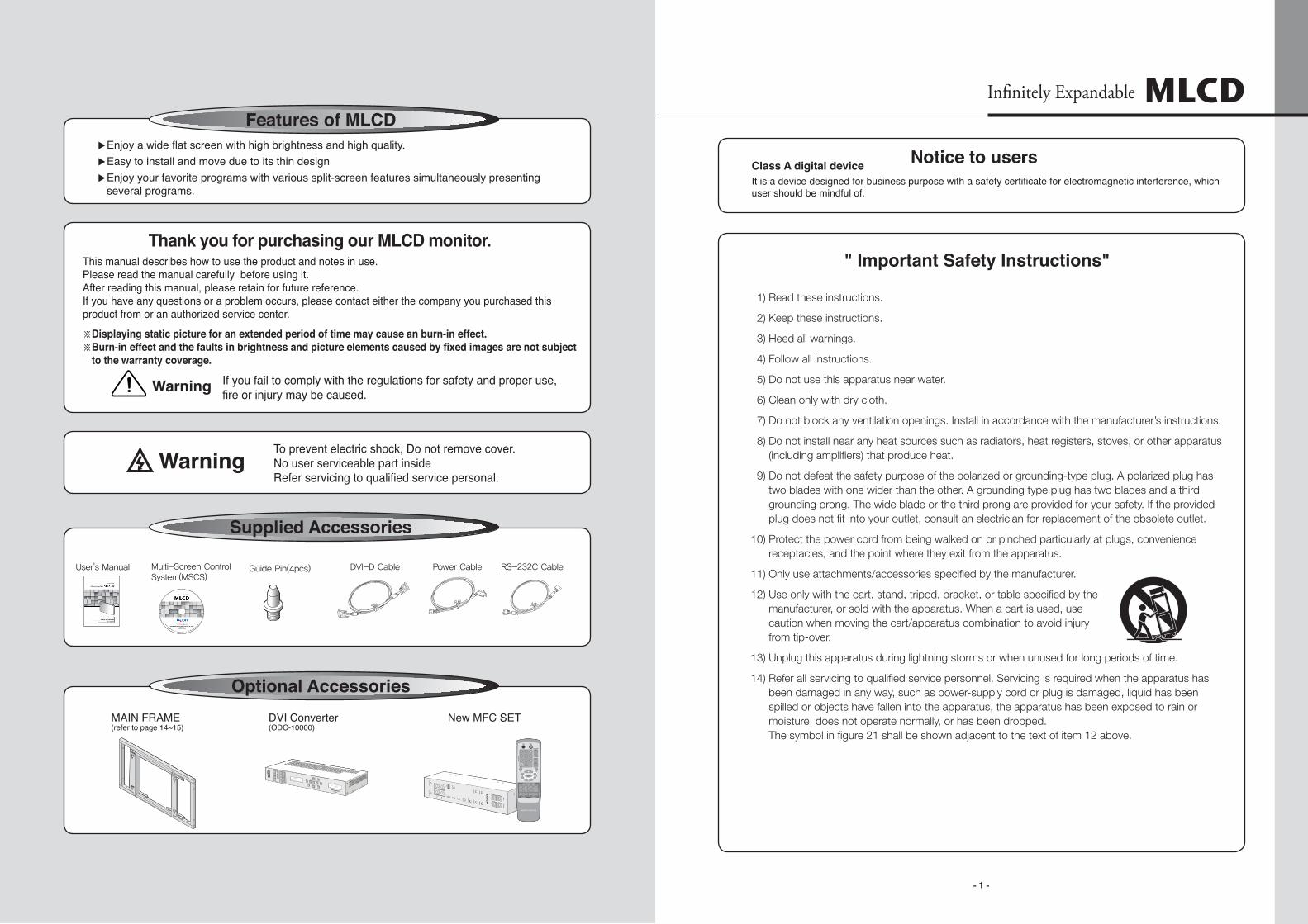
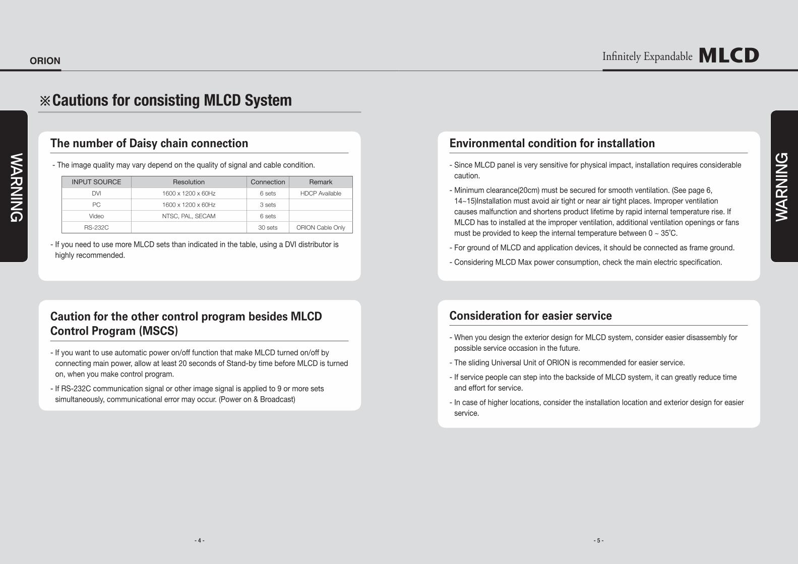
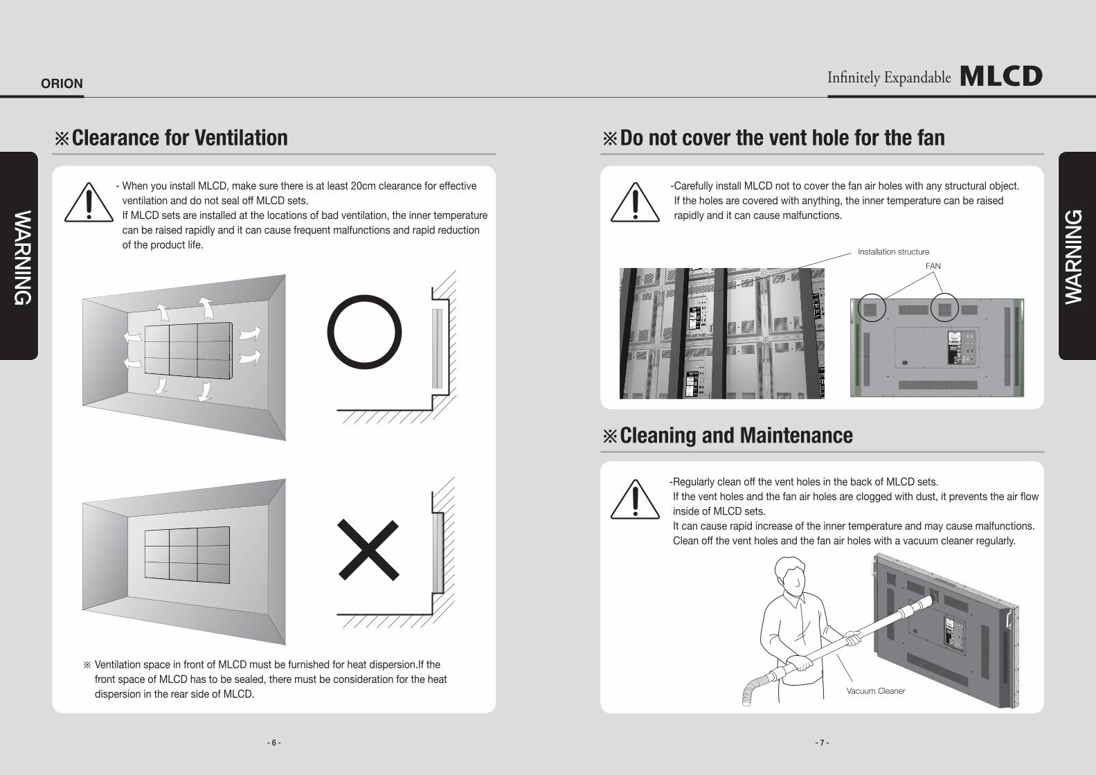
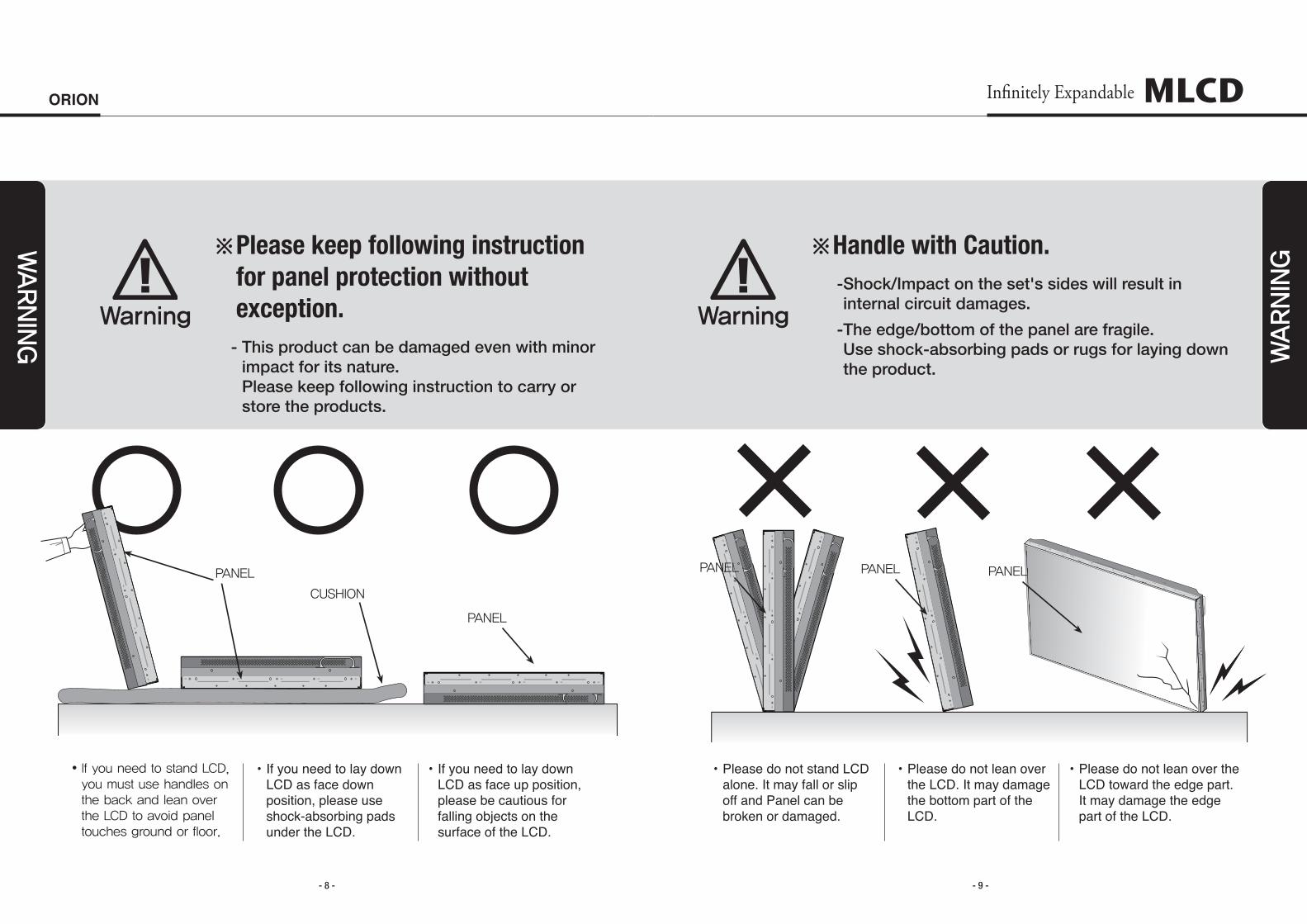
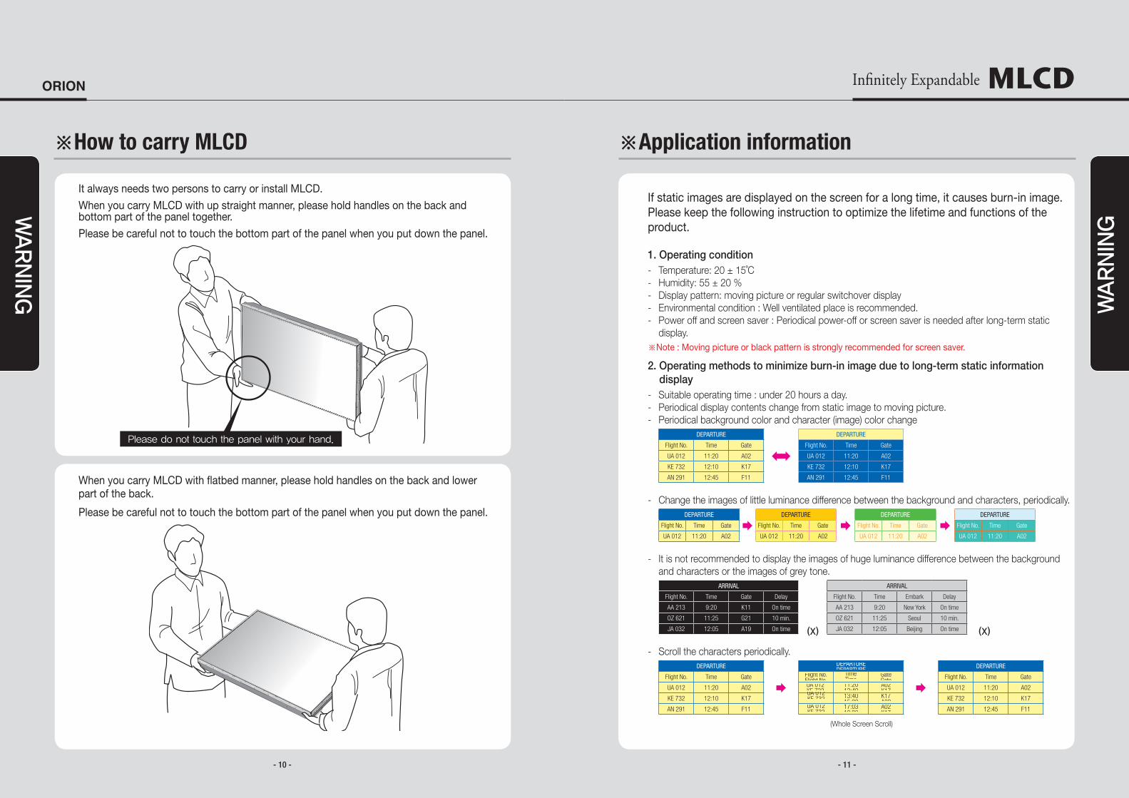
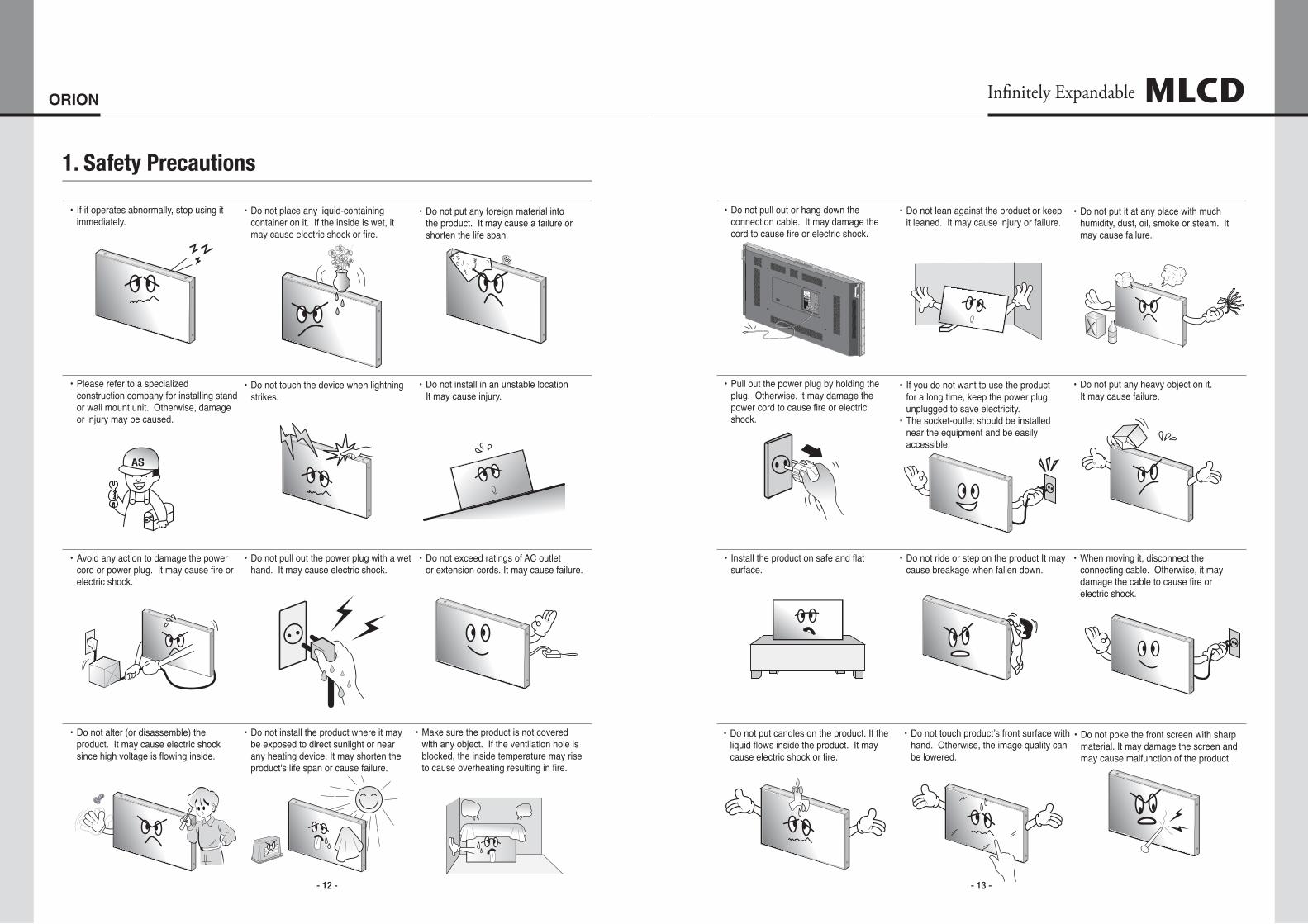
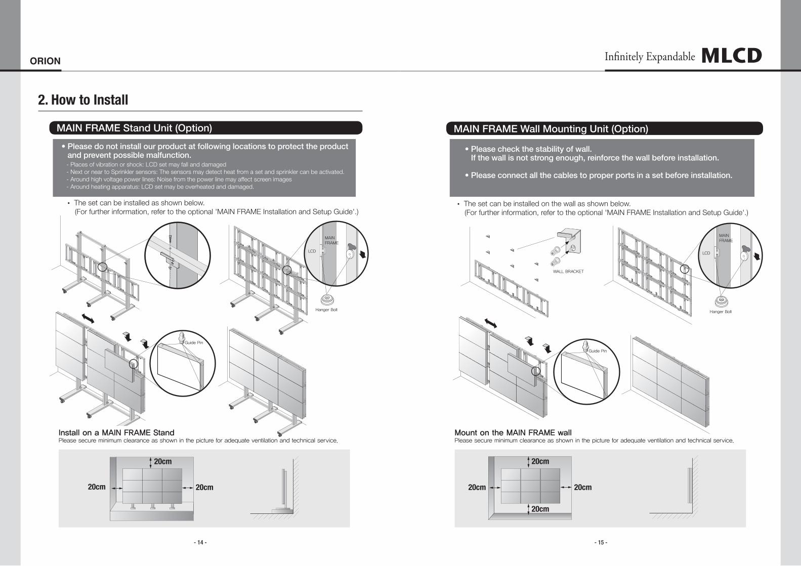
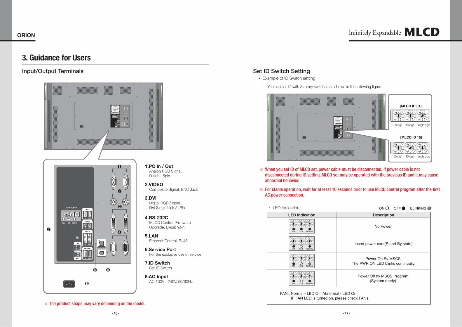
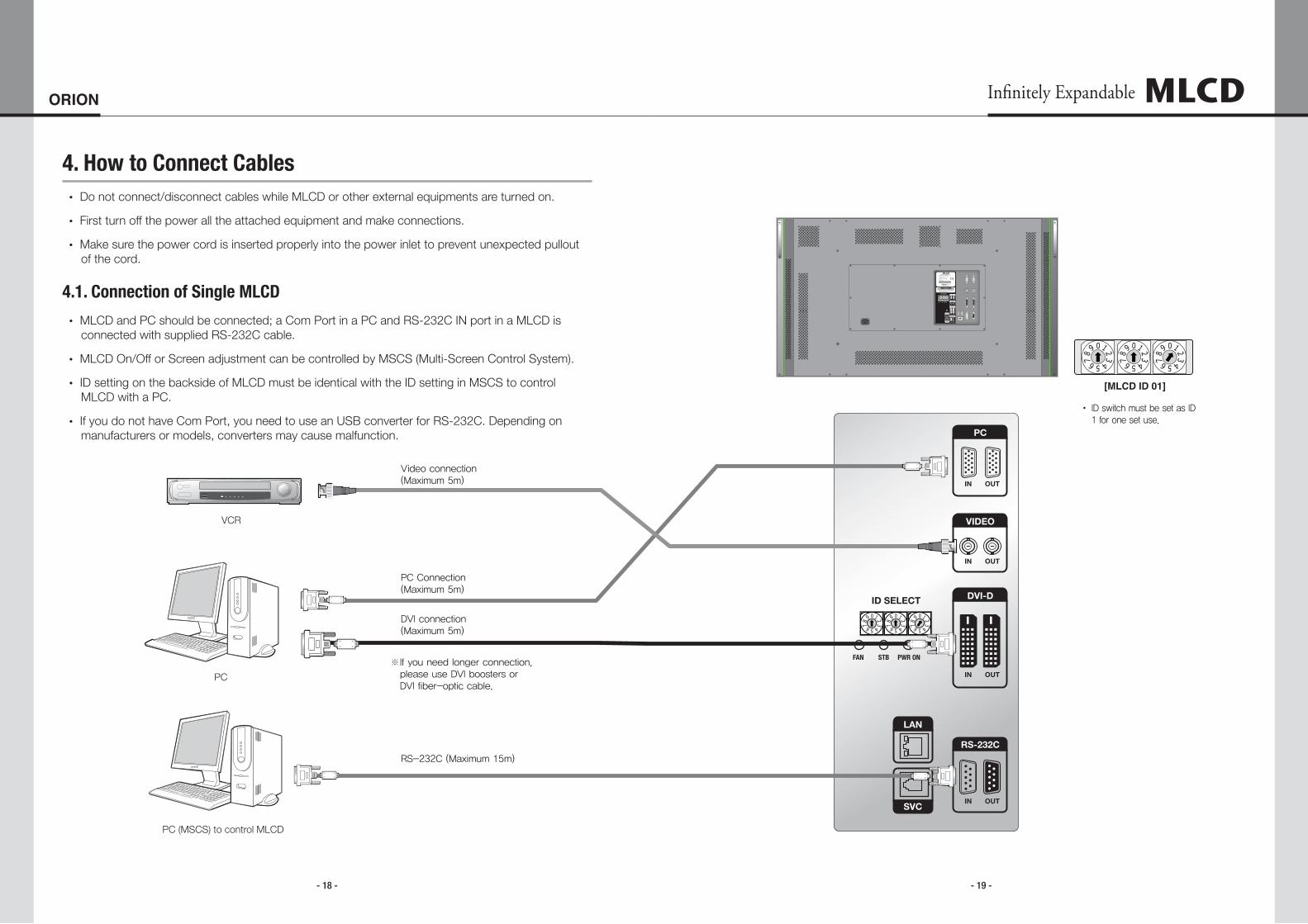
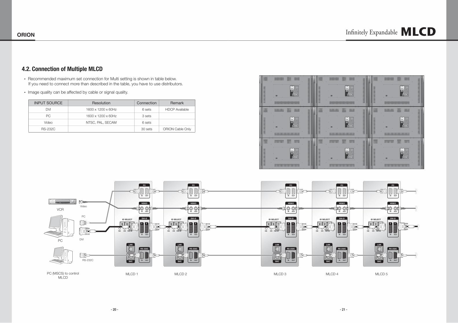
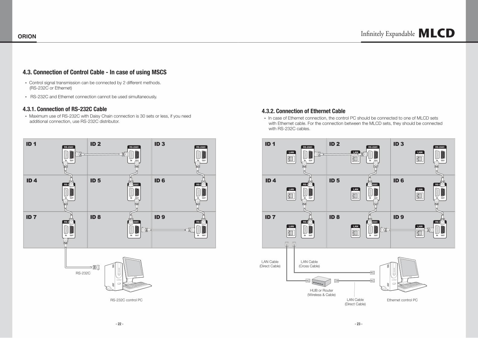
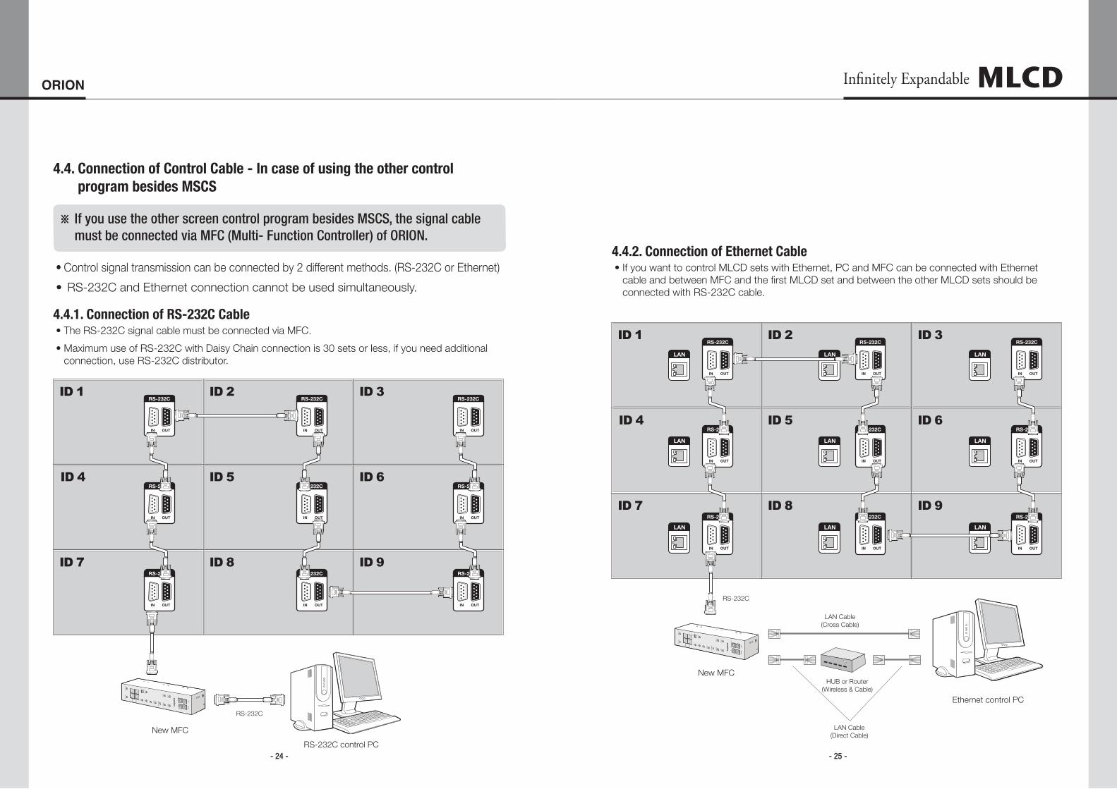
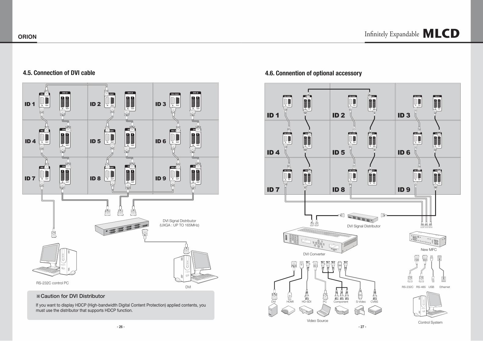
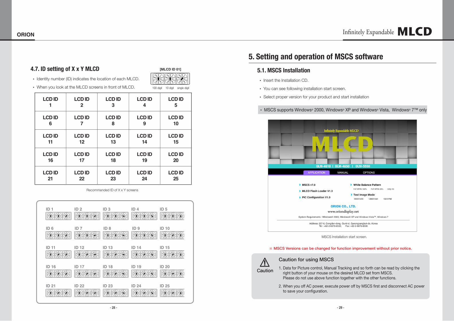
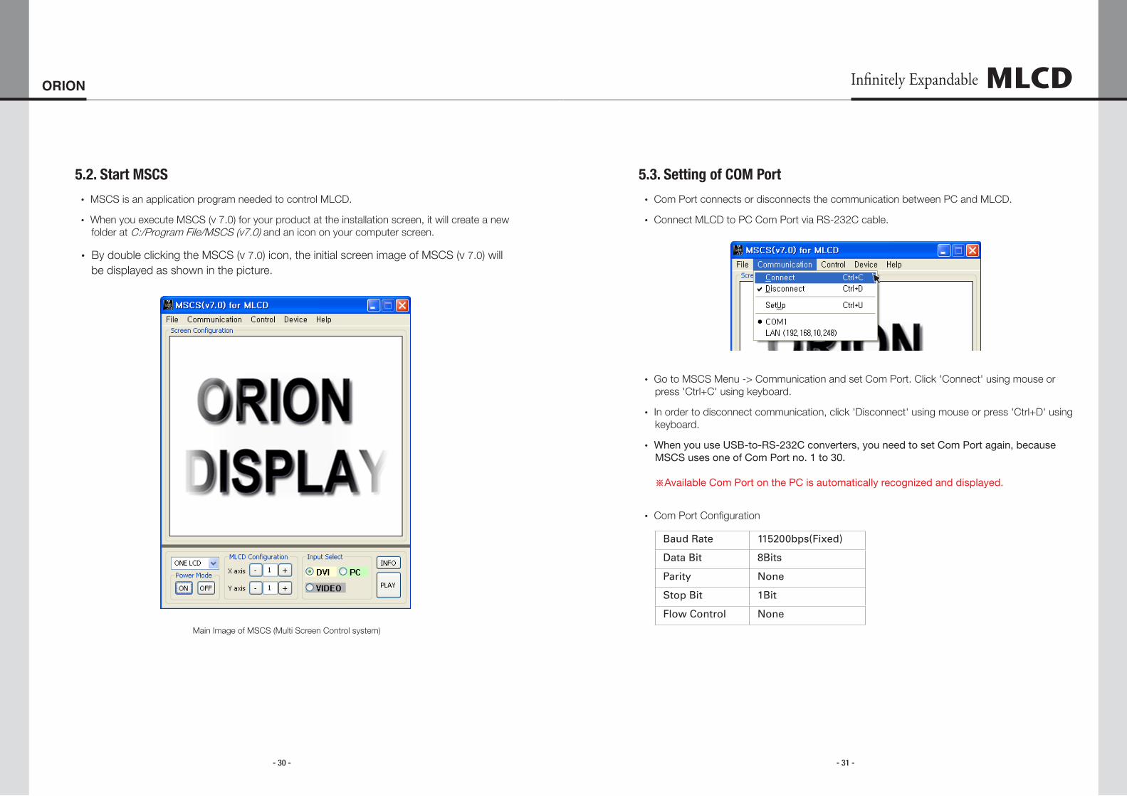
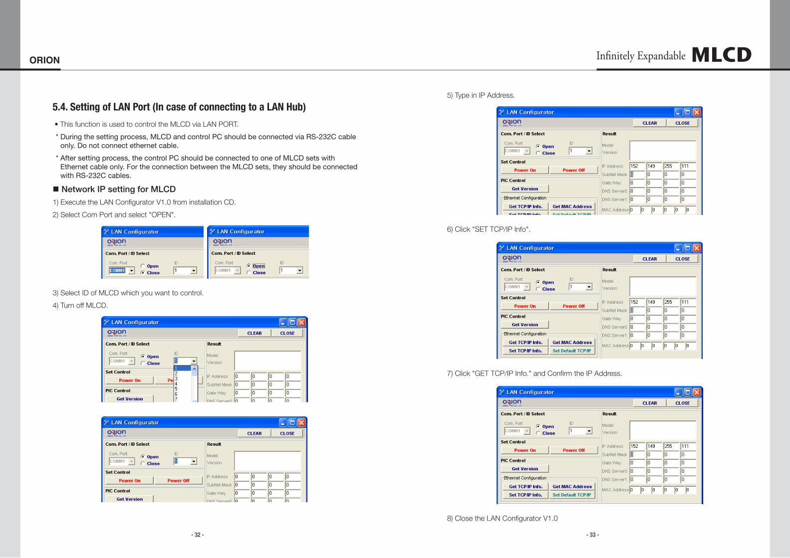
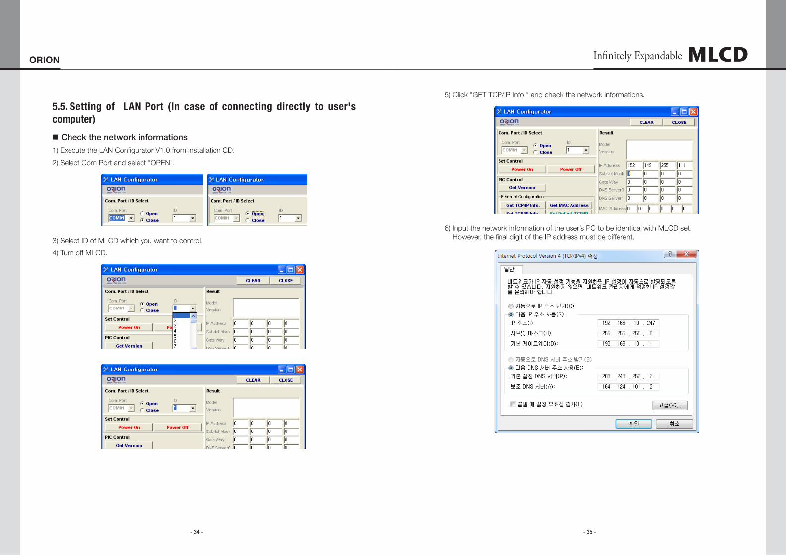
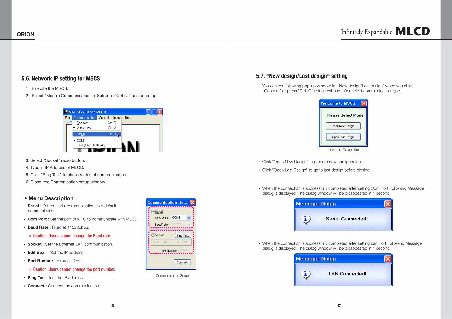
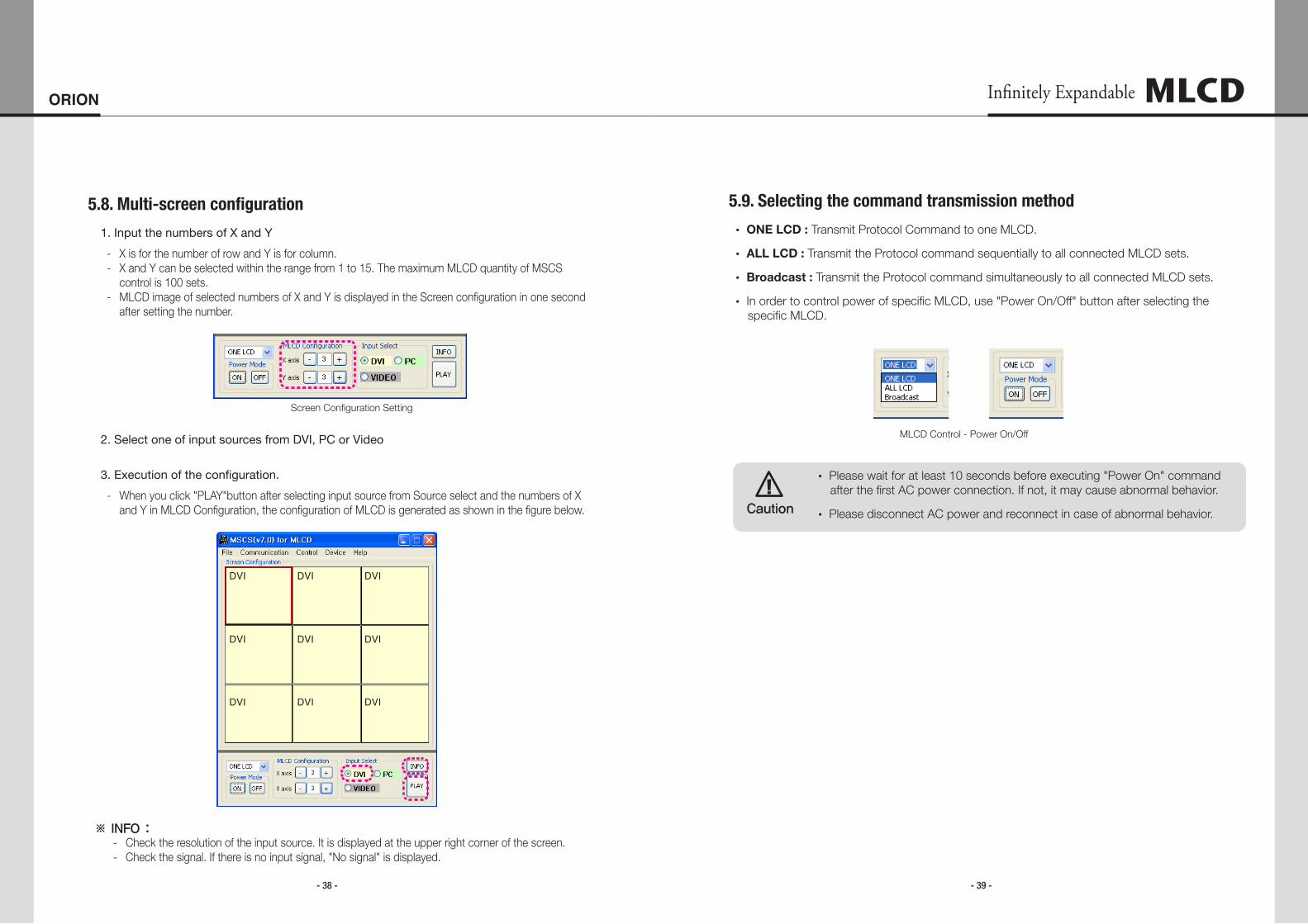
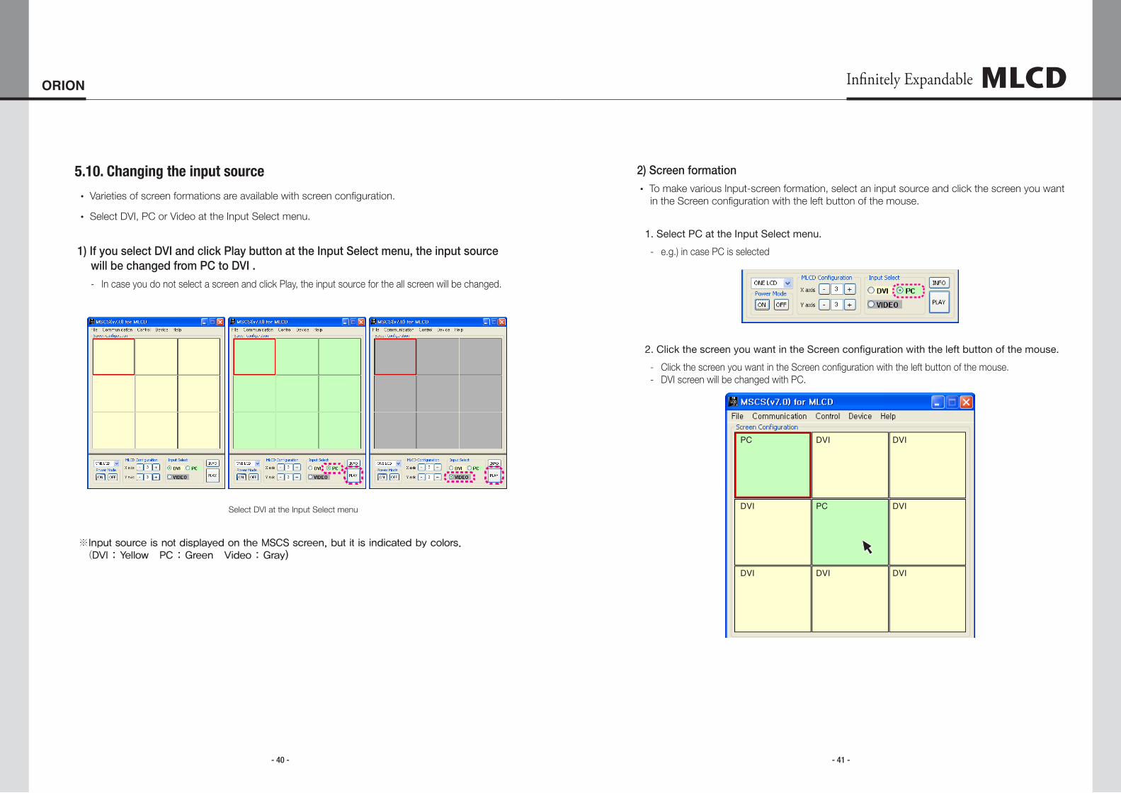
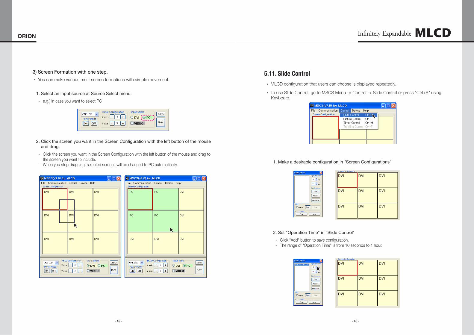
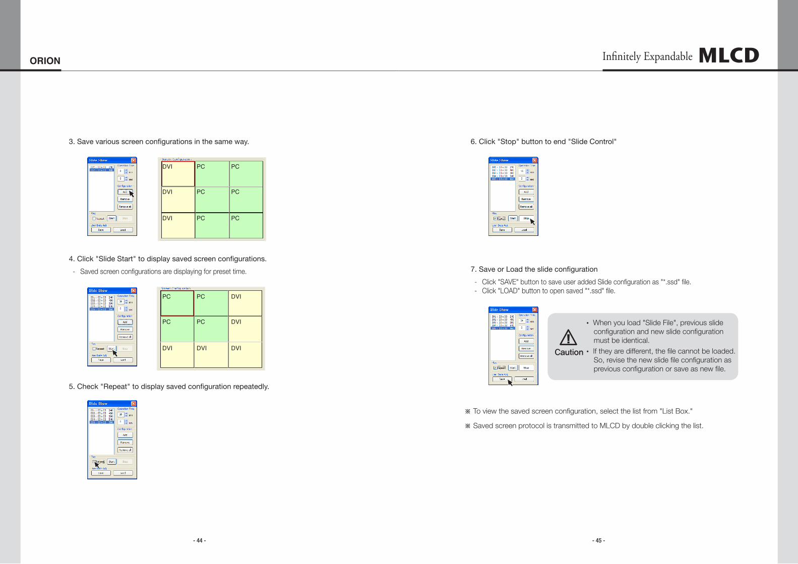
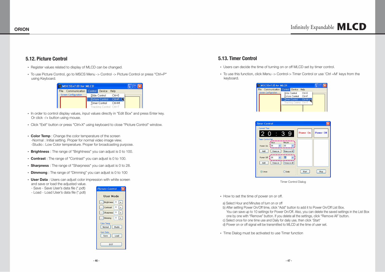
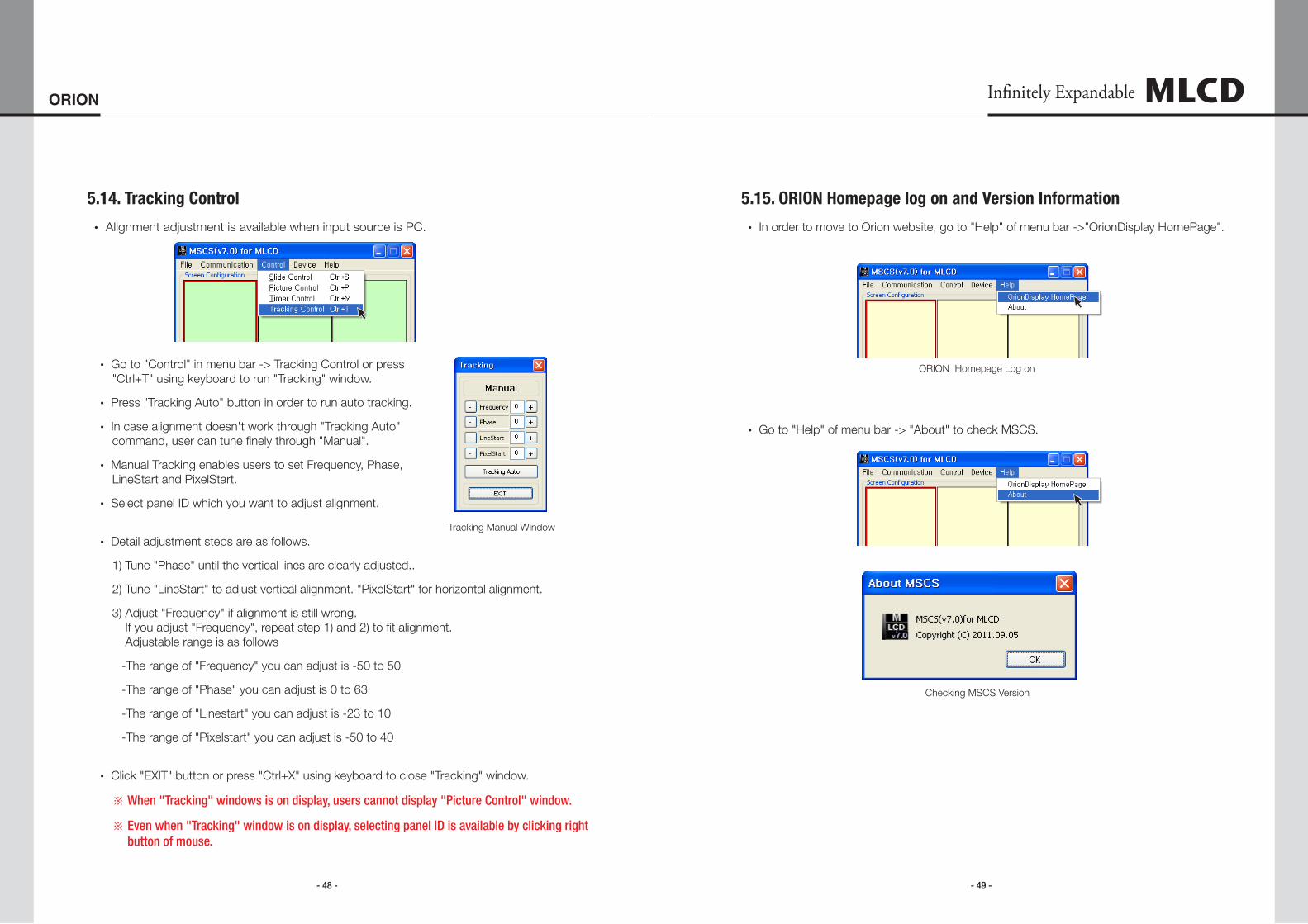
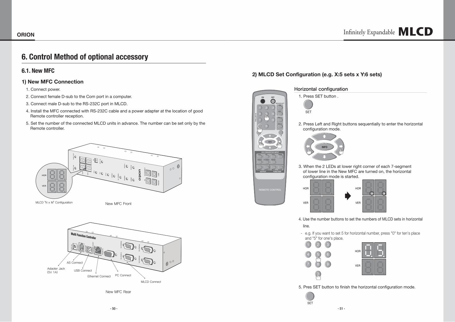
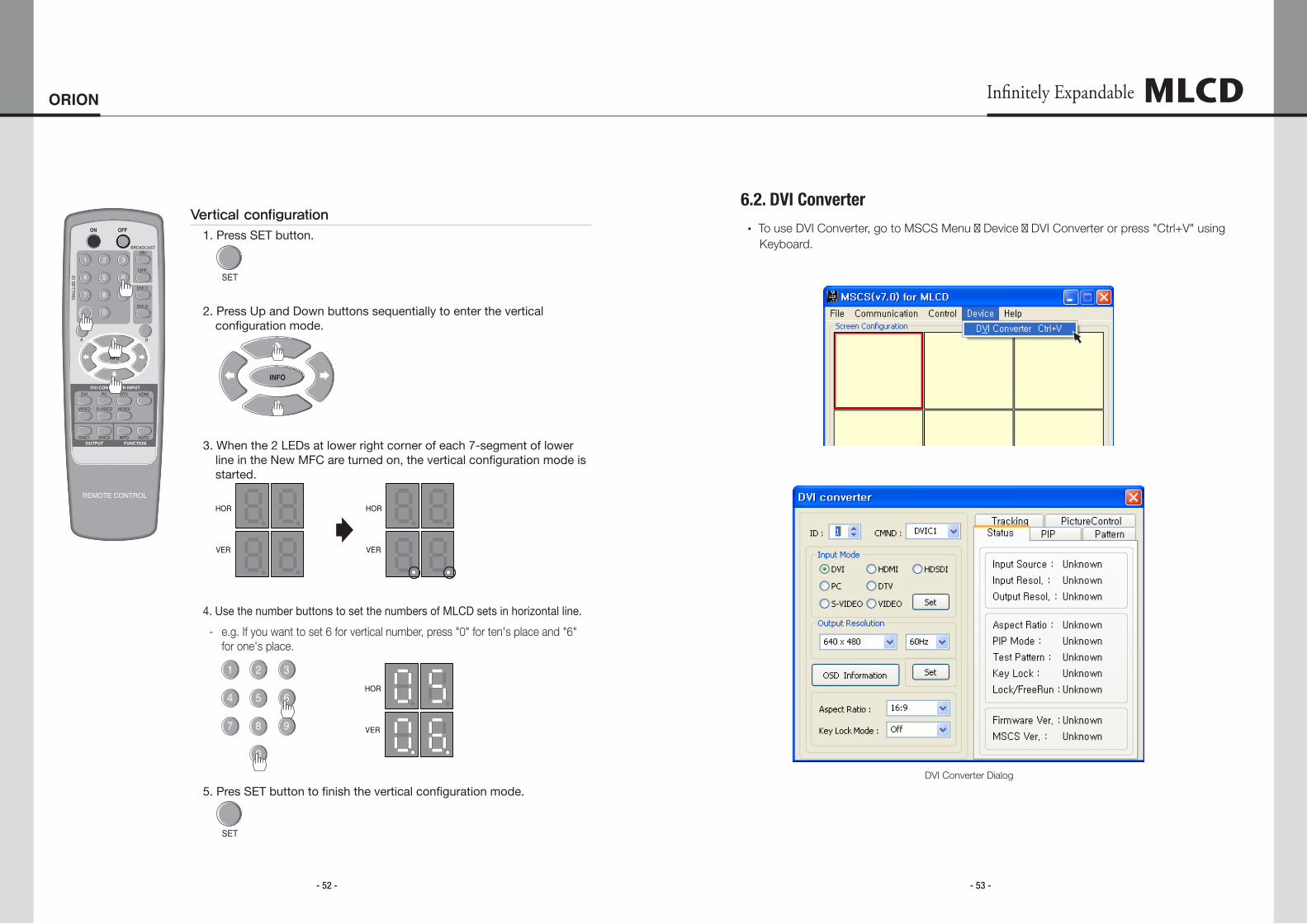
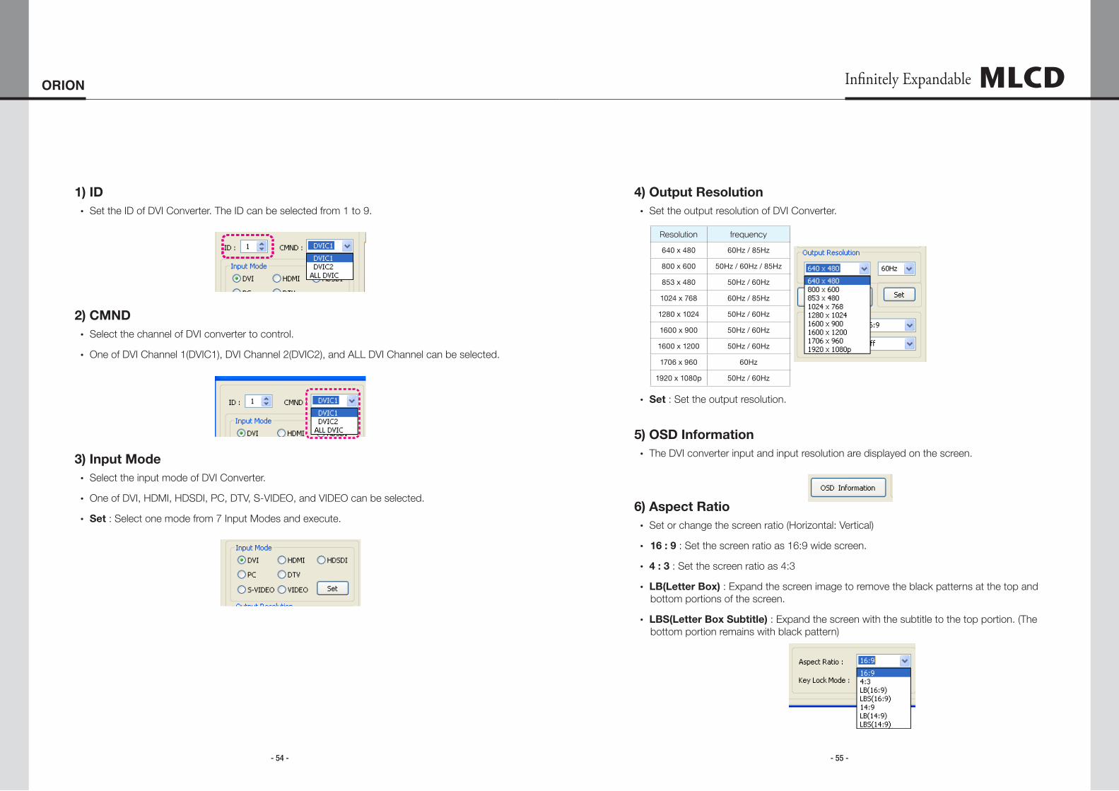
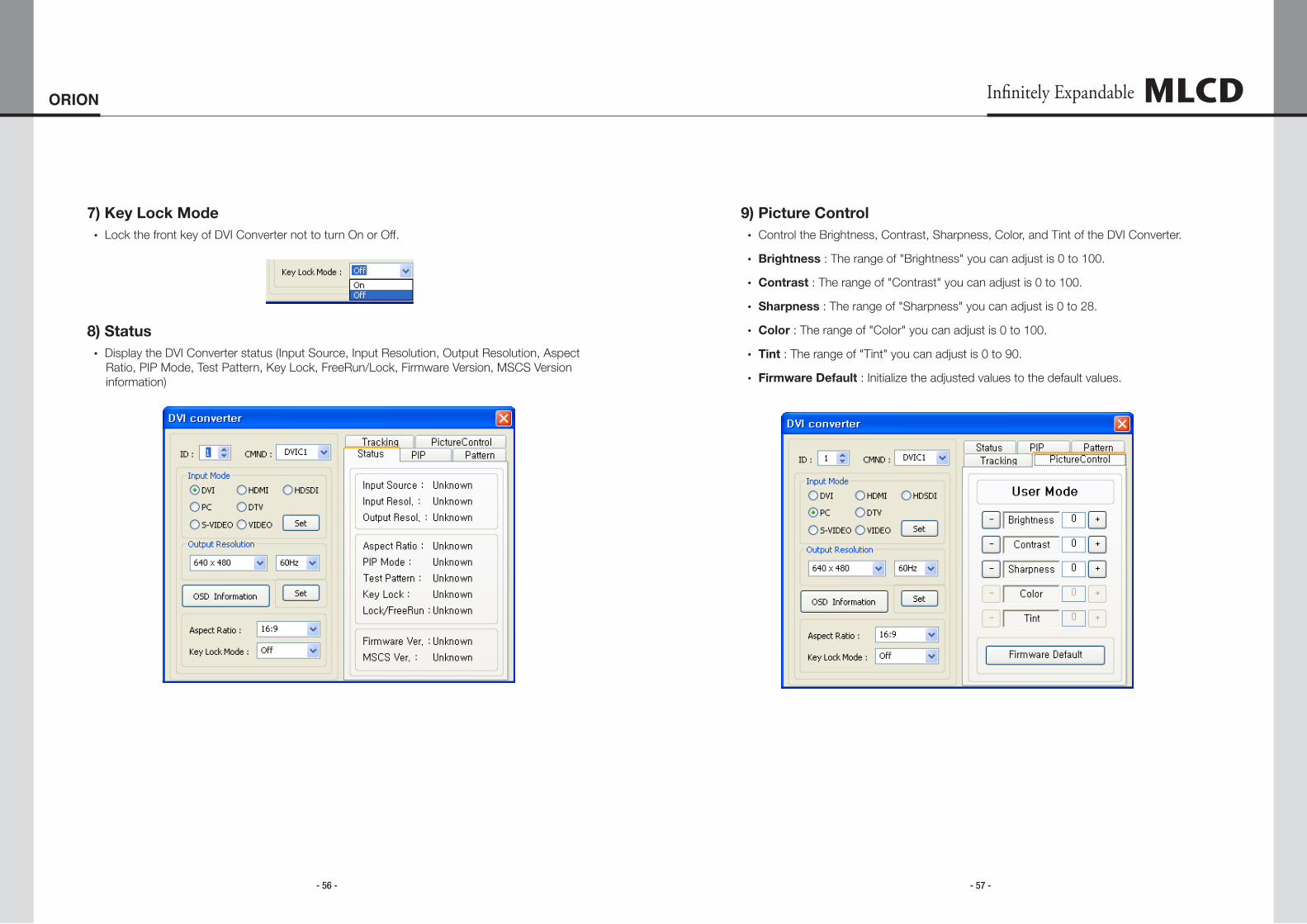
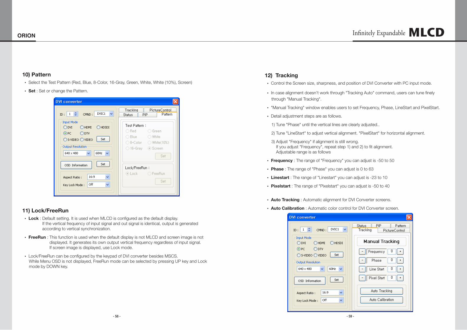
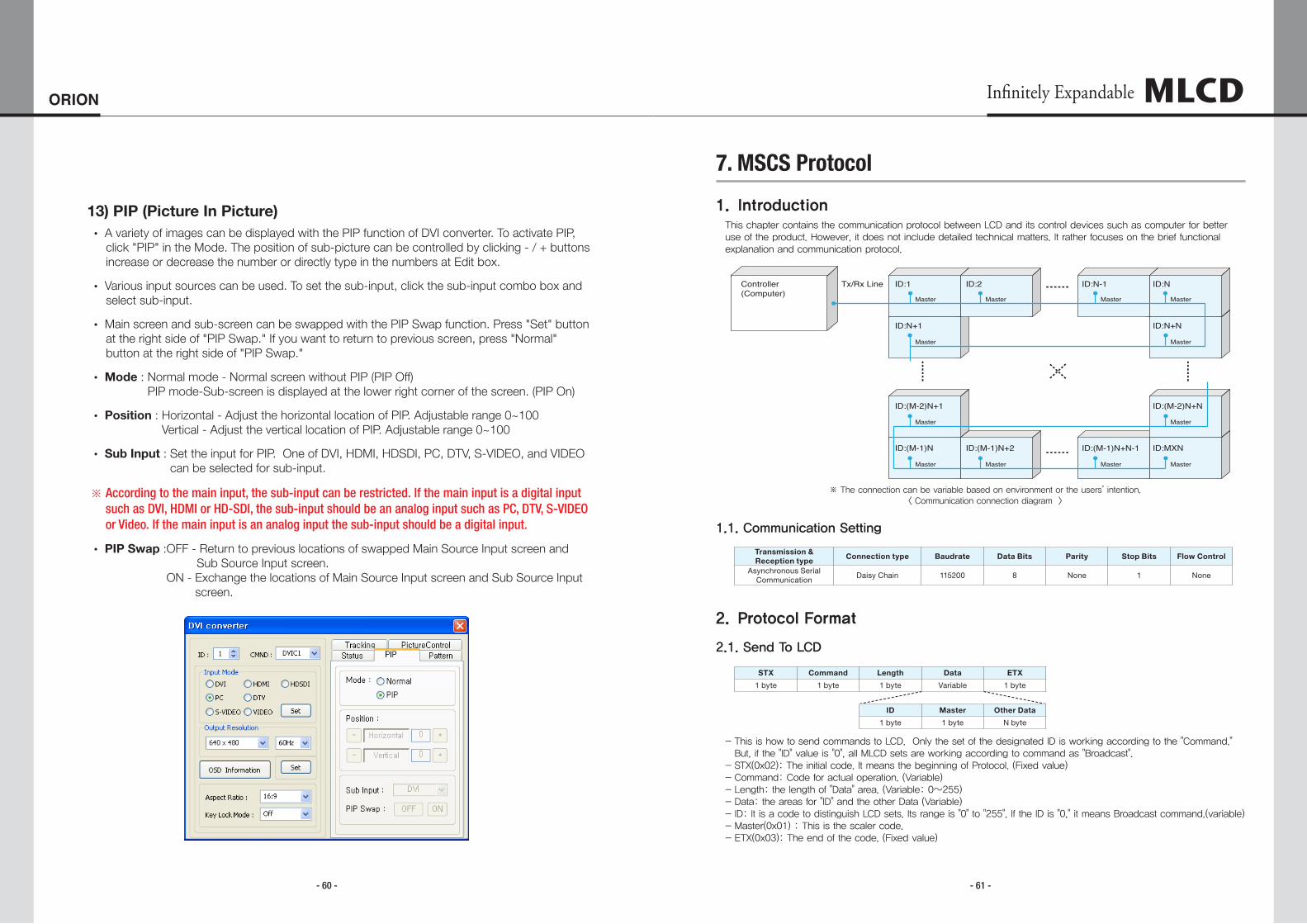
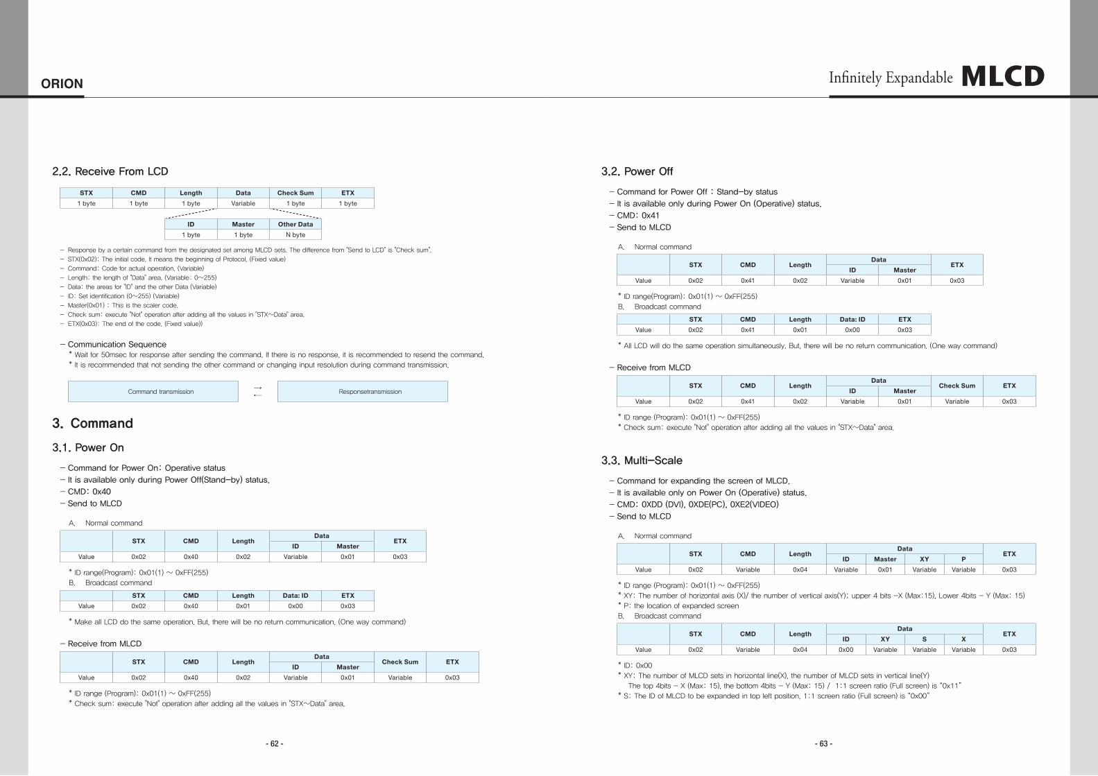
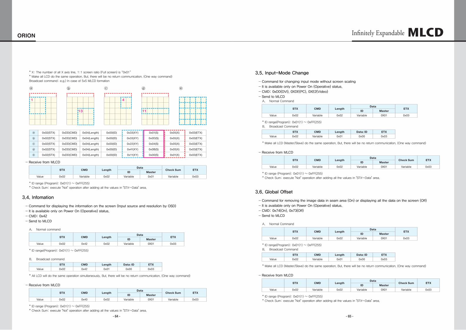
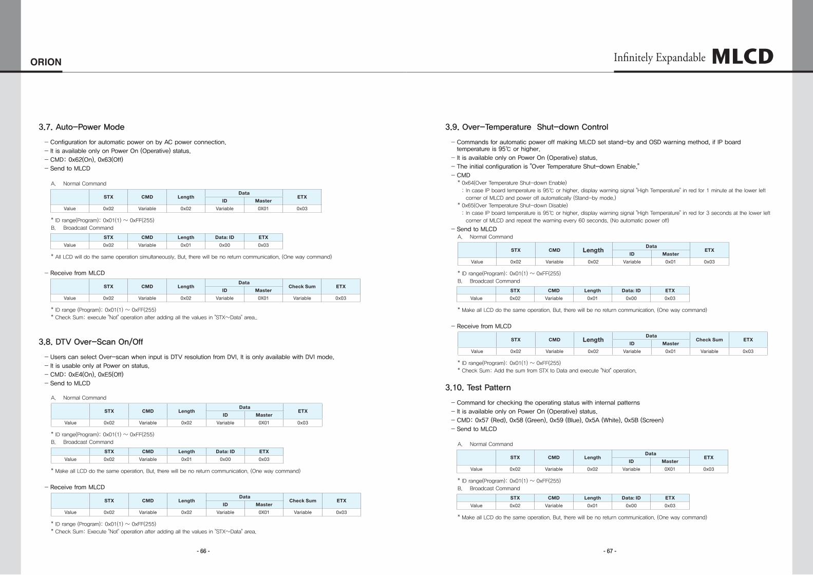
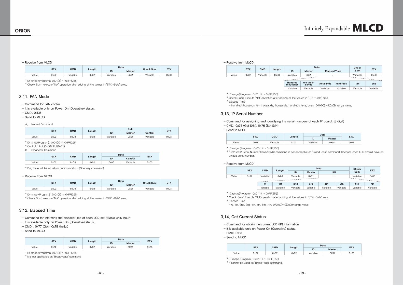
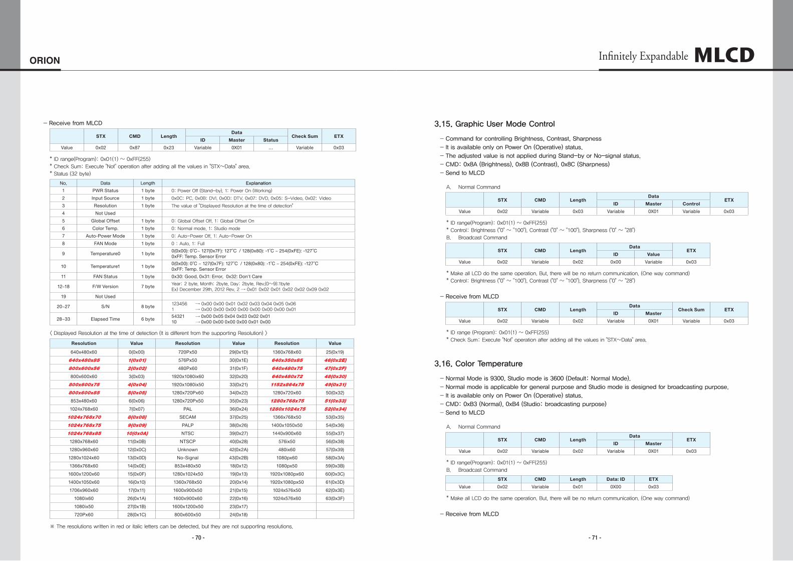
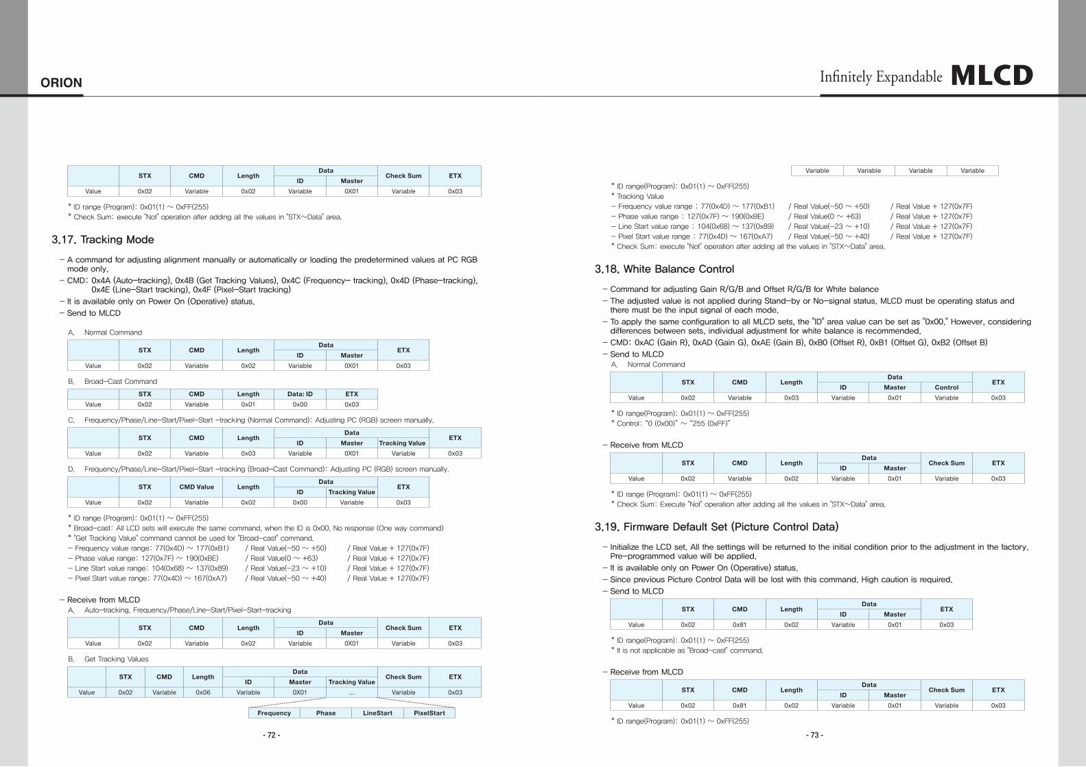
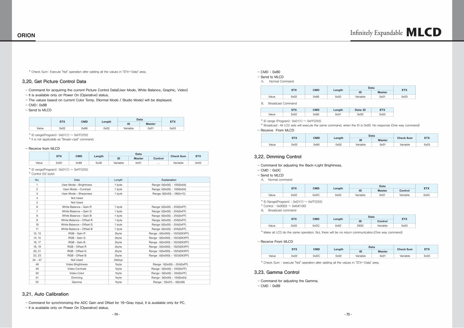
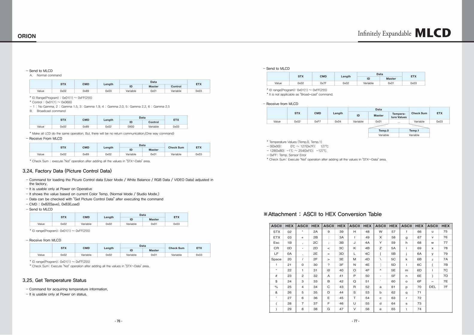
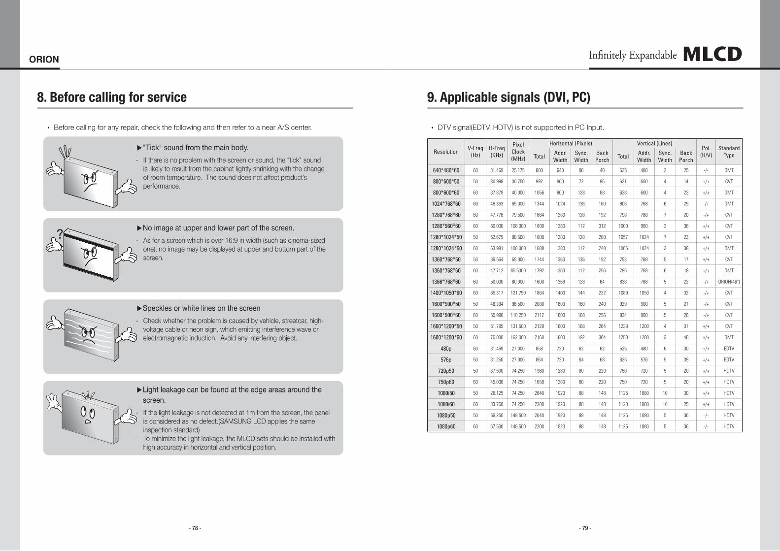
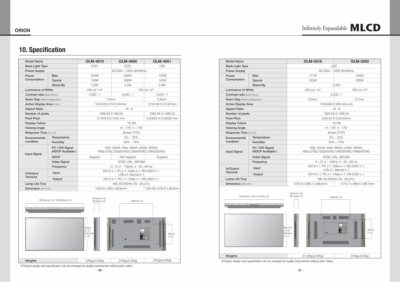
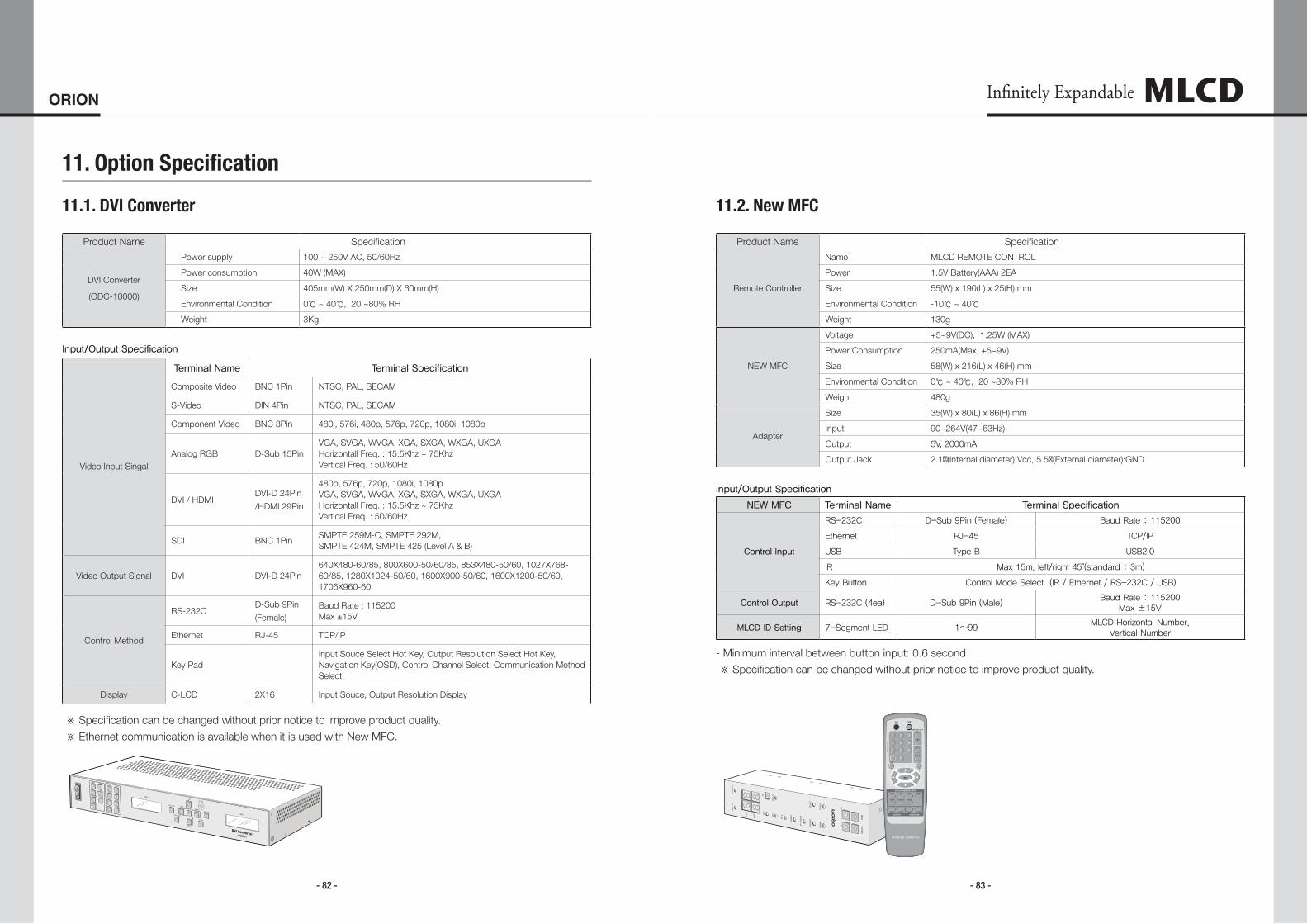
- 84 - - 85 -
ORION Infinitely Expandable
Memo Memo
MLCD


![Super Narrow Bezel[OLM-4610] CCFL BLU LED BLU … Video Wall. 46” With the proven videowall display know-how, OLM-4610/4611, OLM-4651 offer the best proven videowall performances](https://img.pdfslide.us/doc/110x75/5ae08e0a7f8b9ad66b8e4d8e/super-narrow-bezelolm-4610-ccfl-blu-led-blu-video-wall-46-with-the-proven.jpg)