Embed Size (px)
Citation preview

Multi-Carrier ModulationDr. Ahmad GomaaAssistant Professor Electronics and Communications departmentFaculty of Engineering, Cairo Universityhttp://scholar.cu.edu.eg/gomaaContact: [email protected]

Outline• Single carrier (SC) modulation• Shortcomings of SC systems• Multi-Carrier modulation (MCM)
– Main idea– Implementation using IFFT and FFT– MCM in multi-path fading– MCM in multi-path fading– OFDM parameters– Bit-Interleaved Coded OFDM– PAPR– Subcarrier loading– OFDM under RF impairments (CFO, PN, IQI, Doppler)– Single-Carrier Frequency-Division Multiple-Access (SC-FDMA)

Single Carrier (SC) Modulation• Bits are modulated according to M-QAM or M-PSK• Modulated symbols are passed through a pulse shaping filter (e.g., Square-Root Raised Cosine shaping filter (e.g., Square-Root Raised Cosine (SRRC) filter)• Output is up-converted to the carrier frequency (fc)

Single Carrier Modulation
M-QAM(or M-PSK)bits
Pulse Shaping filter
π/2
Pulse Shaping filter
Pulse shaping filter specifies symbol rate & signal shape in frequency-domain

Single Carrier (SC) Modulation• Transmitted signal passes through multi-path channel• Inter-Symbol Interference (ISI) occurs due to the channelthe channel• The receiver has to apply equalizers to extract the modulated symbols• Complex equalizers and not even optimal!

Multi-path channel
Transmitter Receiver
Reflecting object (car, building, ….)
Reflecting object (car, building, ….) Channel impulse response

Multi-path channel• Multi-path channel causes inter-symbol interference (ISI)• Need equalizers at the receiver to reverse the channel effect• Baseband model• Baseband model
][][][][0
nzknxkhny L
k
Channelhx[n]
z[n]
y[n]ModulatedQAM symbols
Receiver noise
Received samples
Convolution between x[n] and h

Multi-path channel• y[n] is not only function of x[n] but also function of previous symbols {x[n-1], x[n-2], …. x[n-L]}• These previous symbols act as interference on • These previous symbols act as interference on the current symbol x[n]• Need to extract x[n] from y[n]• This is done using equalizers

EqualizersChannel
hx[n]
z[n]
y[n]ModulatedQAM symbols
Equalizerw
][ˆ nx
M
Noise
M
knwnznwnhnx
knykwnwnynx][][][][][
][][][][][ˆ
[n] be should
0
If w[n] is designed to make h[n]*w[n] = δ[n], then we force the ISI = 0 Zero-Forcing equalizer effect on noise?

Equalizers1)()(
][][][
fWfHnnwnh
Channel impulse responseChannel frequency response
Time-domainChannel impulse response
nf
Time-domainTo Frequency-domain
As channel length (rms delay spread) increases, frequency-selectivity increasesOne-tap channel has flat frequency response
h(n)H(f)
Dip frequencies

Shortcomings of SC systems• For W(f) H(f) = 1, W(f) will have large magnitude at dip
frequencies• W(f) will enhance the noise at these dip frequencies• When looking in time-domain, these enhanced noise will
impact the whole time-domain all symbols are impacted by impact the whole time-domain all symbols are impacted by noise enhancement
• ZF equalizer Noise enhancement Poor performance!Solution? (Multi-Carrier Modulation)

Multi-Carrier Modulation - Main Idea• If we can divide H(f) into N subbands (subchannels or subcarriers), each of small BW• Then, channel is approx FLAT over each band• We equalize every subcarrier alone by dividing by the channel gain at this subcarrier• We transmit 1 QAM symbol over every• We transmit 1 QAM symbol over every
subcarrier• In receiver, we divide received signal
into N subcarriers, divide every subcarrierby channel gain at this subcarrier to detectQAM symbol at this subcarrier
• Equalizer design is much easier No convolution• Only QAM symbols at dip frequencies will suffer No effect on other QAM symbols as they are transmitted on other subcarriers
……
Subcarrier (channel approx flat)
f

Multi-Carrier Modulation - Main Idea• For QAM symbol to be transmitted over a small BW symbol duration has to be large small data rate?• Every symbol will have small symbol rate but we transmit N symbols in parallel Effective rate is high!
5us cos(w1t)Example
1us Serial
to Pa
rallel
Bit rate = 1 bit / 1us= 1Mbps
... cos(w5t)
Example
Bit rate = 5 bits / T= 5 bits / 5us= 1 MbpsT

• In general, we have QAM symbol (which is complex a+jb) rather than just BPSK symbols (which are real as in the previous example)• To modulate Xk = ak+jbk over subcarrier k, we need exp(jwkt) and rather than just cos(jwkt)
Multi-Carrier Modulation - Main Idea
tjX kk exp• So, we can write the total output as
duration Symbol Total
0 ,exp)(1
TTttjXtx N
kkk
k k kXk = ak+jbk QAM symbol

• How to choose wk’s?• To easily separate these N subcarriers at the receiver, we need them to be orthogonal, i.e.,
Multi-Carrier Modulation - Main Idea
T
tllkk dttjXtjX
00expexp
• To satisfy this, we can show that
NkkTk ,.....,2,1 ,2
TttTkjXtx N
kk
0 ,2exp)(
1

• In digital domain, set t = n Ts
MCM – Implementation with IFFT
ss
N
ksks T
TnTnTTTknjXnTx
00 ,2exp)(
1
This equation can be effectively implemented using This equation can be effectively implemented using Inverse Fast Fourier Transform (IFFT)
N-pointIFFT{X1,X2,….XN} {x(0), x(1),…. x(N-1)}
NnNknjXnx N
kk
0 ,2exp)(
1

• For x(nTs) = x(n), we need
• We choose the sampling time (Ts) to be total symbol time (T ) over number of subcarriers (N)
MCM – Implementation with IFFT
NTTT
TN ss
number of subcarriers (N)• Since we choose the subcarrier frequencies as:
• Then, subcarrier bandwidth is the difference between any two subcarriers which is:
NkkTk ,.....,2,1 ,2
TfBWSubcarrier kk 122 1

• Hence, the total BW of the system is
MCM – Implementation with IFFT
sTTNfN
BWsubcarrierssubcarrierofNumberBWT1
otal

MCM – Waveform in time-domainNnN
knjXnx N
kk
0 ,2exp)(
1
Time-domain signal = weighted summation of sinusoidal signals of frequencies {k/N, k=1,2,…,N}Total symbol duration = T
nTs0 N-1
Freq = 2/N
Freq= 1/NMultiplied by X1
Multipliedby X2
Every subcarrier carriesOne QAM symbol
Total symbol duration = T
Ts

MCM – Waveform in frequency-domainSignal in Frequency domain
Subcarrier spacing = 1/T
At the peak of any subcarrier,contributions from all other subcarriers = zeros Orthogonal

• From the previous figure, we clearly notice the subcarriers are orthogonal to each other• This system is called OFDM (Orthogonal Frequency Division Multiplexing) where orthogonal frequency comes from the fact that the subcarriers are orthogonal to each other• In the receiver, how to recover Xk from x(n) ?• Exploit that the subcarriers are orthogonal as follows:
MCM – Subcarriers orthogonality
• Exploit that the subcarriers are orthogonal as follows:
• We multiply x(n) by the conjugate of the kth subcarrier and run the summation.• This will null out all subcarriers except for the kth one, it will give NXk• We divide by N to get Xk
NkNknjnxNX N
nk
1 ,2exp)(1ˆ 1
0

• This previous equation is exactly what FFT (Fast Fourier Transform) does• So, in Tx we run IFFT and in Rx we run FFT
MCM – IFFT/FFT implementation
QAMmodbits
Serial
to Pa
rallel
N-poin
t IFFT
Paralle
l to Ser
ial
QAMdemod
kX kX bitsPar
allel to
SerialN N
Serial
to Pa
rallel
N-poin
t FFTN N

• This works great if channel is AWGN with no multipath, i.e., channel is flat with no frequency selectively• Even the single-carrier case works great with flat channel (no multi-path) without the headache of
MCM in multipath fading
channel (no multi-path) without the headache of FFT and IFFT• Now, what if there’s multi-path channel?

MCM in multipath fading• Consider a multipath channel with only 2 paths:
A direct path with zero delay and another path with some delay• Focus on the subcarriers 1/N and 2/N• In the next page, the solid curves are the two • In the next page, the solid curves are the two subcarriers of the direct path (no delay)• The dashed curve is the delayed version due to the delayed path• We plot only the delayed path of subcarrier 2/N to avoid crowding

MCM in multipath fading
Now, to get X1, we multiply the whole received signal by the blue signal and integrate (sum)This will cancel out the solid red signal BUT not the dashed red because it’s not a COMPLETESinusoidal. So, we will have inter-carrier interference (ICI) from X2 and other subcarriers on X1

MCM in multipath fading So, multi-path fading ICI in OFDM How to solve that? Solution is to make the dashed sinusoidal a COMPLETE wave, i.e., Solution is to make the dashed sinusoidal a COMPLETE wave, i.e., have an integer number of periods in the integration (summation) time This is done using Cyclic prefix, i.e., copy the last portion of the totalOFDM symbol and put it before the beginning of the OFDM symbol

MCM in multipath fading
Copy

MCM in multipath fading
Now, the delayed version of subcarrier 2 will have an integer number of periods4within the OFDM symbol duration (summation interval), so it will be cancelled outwhen we multiply the received signal by subcarrier 1 and integrate No ICI

MCM in multipath fading• How to choose the length of cyclic extension?• It should be chosen such that it’s greater thaneffective channel length• Cyclic extension converts the linear convolutionbetween Tx signal and channel into Cyclic Convolutionbetween Tx signal and channel into Cyclic Convolution• Cyclic convolution in time-domain is equivalent tomultiplication of FFTs in Frequency-domain• FFT of transmitted signal is simply the QAM symbols(Xk)• FFT of the channel is the channel frequency response

MCM in multipath fading
tzthtxty
get weFFT Taking)()()()(
signal Received Circular convolutionThanks to Cyclic extension!
NkHYX
NkZHXY
kkk
kkkk
1 ,ˆ knowledge, channel Assuming
1 ,
Here, equalizer is ONLY 1-tap and it’s Maximum Likelihood (ML) OptimalML minimizes error rate

MCM – Cyclic ExtensionCyc.Exten
IFFT output (N samples) Cyc.ExtenIFFT output (N samples)
OFDM symbol OFDM symbol
…..time
OFDM symbol 1 OFDM symbol 2
• Cyclic extension Prevents multipath channel from introducing ICI after taking FFT at the receiver• Cyclic extension is also called Cyclic Prefix• Does it have another function ?

• When OFDM signal passes through multi-path channel, everysymbol will leak into its successor (the symbol coming after it)• To prevent inter-symbol interference (where symbol hererefers to OFDM symbol), we need to have Guard Intervalbetween OFDM symbols• Thanks to its position lying between successive OFDMsymbols, Cyclic Extension acts also as Guard Interval
MCM – Cyclic Extension [Guard Interval]
symbols, Cyclic Extension acts also as Guard IntervalIFFT output (N samples) IFFT output (N samples)
timeOFDM symbol 1 OFDM symbol 2Leakage of OFDM symbol 1Does NOT reachOFDM symbol 2

MCM – Pilot and Guard subcarriers
Nused Number of used subcarriersZEROS ZEROS

OFDM parametersParameter Definition Notes
Ts Sampling time Ts = 1/B = 1/bandwidth (seconds)Tcp
Guard interval length (Cyclic Prefix length) Tcp = NcpTs > Effective channel length (seconds)T IFFT output length T = NTs = 1/Δf (seconds)
Ttot OFDM symbol length Ttot = T+Tcp= (N+Ncp)Ts (seconds)Ttot OFDM symbol length Ttot = T+Tcp= (N+Ncp)Ts (seconds)Δf Subcarriers frequency spacing = frequency of 1st subcarrier Δf = 1/T = B/N (Hz)B OFDM bandwidth B = 1/Ts = N Δf (Hz)N Number of subcarriers(IFFT size) = # samples in IFFT output N = B/Δf = T/Ts
Bused Occupied OFDM bandwidth Bused = Nused Δf (Hz) Nused Number of used subcarriers

OFDM parameters (Cnt’d)Parameter Definition Notes
Bguard Guard subcarriers bandwidth B = Bguard + Bused (Hz)Nguard Number of guard subcarriers N = Nguard + Nused
Ncp # samples in cyclic prefix Ncp = Tcp/Ts
f Sampling rate f = 1/T = N Δf (Hz)fs Sampling rate fs = 1/Ts = N Δf (Hz)
How to choose T = 1 /Δf ?
length channel1α bandwidth Coherence
subcarrierover channelFlat bandwidth Coherence)efficiencyr (rate/powe overhead CP Reasonable4
al
CPf
TT

4G LTE OFDM parameters
(N)
Licensed BW 3 MHz
= B (OFDM BW)
IFFT output length (T) = 1 /subcarrier spacing (Δf) = 1/ 15000 = 67 usNused = Bused/Δf 72+1(DC) 180+1 300+1 600+1 900+1 1200+1Nguard = N-Nused 55 75 211 423 535 847Bused = Nused Δf (MHz) 1.08 2.7 4.5 9 13.5 18
BW efficiency = Bused /licensed BW x 100 % 86 % 90 %

4G LTE spectrum
Used subcarriersLeft GuardSubcarriers Right GuardSubcarriers freqLicensed BW Purchased spectrum
Used BW (Bused)
ZEROSZEROS
Licensed BW Purchased spectrum
We transmit zeros on part of licensed BW In air, it accommodates side lopesof used subcarriers side lopes will not get outside licensed BW So we do not interfere with neighboring bandsWe transmit outside licensed BW but we just transmit zeros No interference on neighboring bands
B = fs = sampling frequency

4G LTE spectrum
Side lopes of modulated subcarriers

WiFi OFDM parameters
IFFT size (N) = 64 (52 used subcarriers + 1 DC + 11 guard subaccreirs)IFFT output duration (T) = 1 / subcarrier spacing = 1/(312.5x103)= 3.2 us Cyclic prefix length = Tg = 0.8us = T/4Sample time (Ts) = 1/(20x106) = 0.05 usUsed BW (Bused)= 53 (52 + 1 DC) subcarriers x 312.5 kHz = 16.6 MHz = OBW = Occupied BW

Comments on OFDM parameters• Cyclic prefix (CP) length in LTE > CP in WiFi, why?• Because WiFi works in indoor environment while LTE works outdoor. • In outdoor, channel paths can be reflected from far objects so will come to Rx after long delay Need longer cyclic prefix• What if we use too long CP, much longer than channel length? • Then, we need IFFT output length (T > 4Tcp) to be very long as well
– Channel can vary during OFDM symbol (because it’s too long in duration) Doppler effect ICI See slide– Channel can vary during OFDM symbol (because it’s too long in duration) Doppler effect ICI See slide– Large latency receiver will need to wait too long before it can receive OFDM symbol OFDM detection cannot start before the whole OFDM symbol is received Large latency not suitable for real-time applications (voice/video chatting, gaming, …)
• What if we use too short CP, shorter than channel length?• Interference between successive OFDM symbols (every OFDM symbol will leak into its successor) ISI• Subcarriers orthogonality will be destroyed leading to Inter-Carrier interference (ICI)

• What about subcarriers with DEEP fading?• What if a Narrow-Band Interference (NBI) hits OFDM signal? (e.g., BLUETOOTH into WLAN)
MCM – Deep fading and NBI
……
Deep Fading
Narrow-band Interference (NBI)
OFDM signal

• In case of deep fading, Hk is very small, so dividing by it will amplifythe noise Gives wrong QAM symbol after dividing by Hk
• In case of NBI, noise power seen at impacted subcarriers is highGives wrong QAM symbol after dividing by Hk
MCM – Deep fading and NBI
NkZHXY kkkk 1 ,Large in case of NBISmall in case of Deep fading
kkk
kkk H
ZXHYX ˆˆˆ Large in deep fading and NBI
WRONG detectionkk XX ˆ
Channel estimate

• How to solve this problem?• Answer : Channel coding• Channel coding: Introduce redundancy of information bits(e.g., Repetition code, Convolutional code, Turbo code)• Then, distribute the resulting bits over subcarriers• If a subcarrier is hit by deep fading or NBI, we lose its bits but
Bit-Interleaved Coded OFDM
• If a subcarrier is hit by deep fading or NBI, we lose its bits butwe use the redundancy bits distributed to other subcarriers tocorrectly decode information bits
ChannelCoding Interleaver QAM modulationSer
ial to
Parall
el
N-poin
t IFFTN
Paralle
l to Se
rial
Nbits
Add Cyc
lic Prefi
x

• Example, Use repetition code, every information bit isrepeated 3 times
Bit-Interleaved Coded OFDM
1 0 1 1 1 1 0 0 0 1 1 1ChannelCoding Interleaver1 0 1 1 0 1 1 0 1 BPSKmodulation
NBI
1 0 1 1 0 1 1 0 1
freq
NBI
Subcarrier1 Subcarrier4 Subcarrier6

• Subcarriers 4-6 are hit by NBI their data is wrongly detected• We can still detect the original information bits after decoding
Bit-Interleaved Coded OFDM
1 0 1 1 0 1 1 0 1
NBINBI
freqAfter detection1 0 1 00 11 00 1 0 1
1 00 1 0 11 0 1 00 1After De-Interleaving
After Decoding (Majority Rule)1 0 1
WRONG!
CORRECT!

• Note the importance of the Interleaver!• It distribute code bits among subcarriers, so code bits corresponding to any information bit are assigned to NON-ADJACENT subcarriers, so if one is lost, others are not lost• One possible Interleaver design: Matrix Interleaver • Write code bits row by row in a matrix and read them out
Interleaver design
• Write code bits row by row in a matrix and read them out column by column c1 c2 c3 ……. c10c11 c12 c13 ……. c20c21 c22 c23 ……. c30..c91 c92 c93 ……. c100
{c1 c11 c21 …… c91 c2 c12 c22 …… c92c3 c13 c23 …… c93….….…. .…. c100}
{c1 c2 c3 …… c10 c11 c12 c13 …… c20c21 c22 c23 …… c30….….…. .…. c100}
c1 And c2 separatedby 10 bits!

OFDM Transmitter and ReceiverChannelCoding Interleaver QAM modulation
Serial
to Pa
rallel
N-poin
t IFFTN
Paralle
l to Se
rial
Nbits
Add Cy
clic Pr
efix
Channeldecoding De-Interleaver QAM demod
Paralle
l to Se
rial
N-poin
t FFT
Serial
to Pa
rallel
Nbits
Remove
Cyclic
Prefix..
..
Freq domain Channel equalization (1 tap/subcarrier)Channel is estimated using pilots 1ˆ/1 H
kH/1
NH/1

Peak-to-Average Power Ratio andand
Subcarrier Loading

Subcarrier Loading• If the channel has slow variation over time (e.g., in xDSL)• We can adapt the modulation of each subcarrier• Subcarriers with deep fades loaded with few bits (e.g., BPSK
or QPSK) Low poweror QPSK) Low power• Subcarriers with good channel loaded with many bits (e.g.,
64-QAM) High power• We can design the loading of every subcarrier to maximize
overall throughput (bit rate) Use waterfilling technique

Subcarrier Loading
SubcarrierWith bad Channel Not assigned Any bits (not used)
SubcarrierWith goodChannel Assigned many bits (high QAM) Large power

Subcarrier Loading• Can we use adaptive loading in Single-Carrier systems?• No because by definition adaptive loading is used in multi-
carrier systems • This is one advantage of OFDM over Single-Carrier• This is one advantage of OFDM over Single-Carrier

Peak-to-Average Power Ratio (PAPR)• One disadvantage of OFDM is that it has high PAPR• This means that the peak power is much higher than the
average power
Peak power
Average power
time
OFDM symbol power

Peak-to-Average Power Ratio (PAPR)• OFDM has high PAPR, so what?• After generating OFDM signal, we feed it into Power Amplifier (PA) to
amplify it• Any PA has a linear region and a saturation (non-linear) region• To avoid saturation and generation of non-linear components, we
need to work in the linear region• Hence, we need to push the OFDM signal such that both its peak and
average are within the linear region• This means that most of the time (where average power lies), we will
work in low gain Low efficiency of PA

Peak-to-Average Power Ratio (PAPR)Output signal power Non-linear (Saturation) region
Linear region
Input signal powerMostOf time,We work In lowGain region
High gain region is rarely utilized!

Peak-to-Average Power Ratio (PAPR)• Why does OFDM have high PAPR?
• OFDM signal = Summation of N random variables
NnNknjXnx N
kk
0 ,2exp)(
1
Random variable • OFDM signal = Summation of N random variables• Central Limit Theory Summation of many random variables has
a Gaussian PDF regardless of PDF of every random variable• x(n) is Gaussian distributed for large N (number of subcarriers)• Gaussian random variables have high PAPR, why?

Peak-to-Average Power Ratio (PAPR)Peak Power (rare!)
Average power (Most of time)
Peak power is much higher than average power for large variancePeak power is less likely to happen than average power

• What about PAPR of Single-Carrier systems?• It’s actually lower than OFDM! Why?• In single-carrier (SC), transmitted signal = modulated
Peak-to-Average Power Ratio (PAPR)
• In single-carrier (SC), transmitted signal = modulated QAM signal directly No IFFT
• Hence, PAPR of SC = PAPR of QAM symbol• Consider QPSK What’s PAPR?

Peak-to-Average Power Ratio (PAPR)
PAPR of QPSK
QPSK ConstellationInphase
Quadrature
A
A s1s2
s s4
d1d2
d3 d4PAPR of QPSK s3 s4
M Number of QAM symbols
dB 0Power AveragePowerPeak log10dBin PAPR
122
Power AveragePowerPeak PAPR
2maxmaxPower MaximumPowerPeak 2 2 4
1 1 1Power Average
10
22
22
24
12
12
1
AA
AdPAAdMPM
iiii
i
M
ii
M
ii

Peak-to-Average Power Ratio (PAPR)PAPR of SC with QPSK = 0 dB Very good for PA efficiency If we used OFDM with QPSK, PAPR will be much higherIn terms of PAPR, Single Carrier is better than OFDM!Exercise: Compute PAPR of Single Carrier with 16-QAM

OFDM UNDER RF IMPAIRMENTS

OFDM under RF impairments• Effect of Carrier Frequency Offset (CFO)• Effect of Phase Noise (PN)• Effect of Doppler [Not RF impairment but has similar impact]similar impact]• Effect of I/Q imbalance (IQI)

OFDM under CFO• CFO means that carrier frequency of receiver local oscillator is different from that of the transmitter
fc,Tx fc,Rxπ/2 π/2
fc,Tx fc,Rx
CFO,, fff TxcRxcCFO ≠0 due to inaccuracies of crystal oscillators used at Tx and Rx

OFDM under CFO• Frequency of Crystal oscillator (XO) has manufacturing error measured as part per million (ppm)• ppm = error (in Hz) in every 1 million Hz (1 MHz)• Specifications of XO tells its frequency and expected error in ppm• Example: XO has frequency = 2 GHz with 0.1 ppm
This means we have 0.1 Hz maximum error in every 1 MHzXO frequency = 2 GHz = 2000 MHz• XO frequency = 2 GHz = 2000 MHz
• Maximum error will be 2000*0.1 = 200 Hz• XO frequency = 2 GHz ± 200 Hz• We expect XO frequency to be any where in the range
2 GHz -200 Hz < XO frequency < 2 GHz + 200 Hz • If both Tx and Rx XOs have 0.1 ppm, then maximum carrier frequency offset (CFO) between them is when one of them is
2 GHz -200 Hz while the other is 2 GHz + 200 Hz Δfmax= 400 Hz

OFDM under CFO• At Rx, taking FFT of received signal is equivalent to sampling the received signal in frequency-domain at the locations of subcarriers as follows
Gives QAM symbol carried by red subcarrier with ZERO contributions of other subcarriers

OFDM under CFO• If we have CFO, then this sampling is SHIFTED
Gives QAM symbol carried by red subcarrierwith NON-ZERO contributions of other subcarriersInter-Carrier Interference (ICI)

OFDM under CFO• CFO results in Inter-Carrier Interference• Every carrier sees interference from NEIGHBOURS• Considering any subcarrier, it will see more interference from close subcarriers than from far subcarriers. This is from close subcarriers than from far subcarriers. This is clear from previous figure• How to solve this problem?• Use pilots to estimate CFO and compensate it in time-domain BEFORE taking FFT

OFDM under CFO
knjnjnxX
fNBTfNnjnxnTjnTxnTx
fftjtxtx
N f
sf
sfss
RxcRxcff
2exp2exp)(1ˆget weRx, @ FFT ngAfter taki
11 ,2exp)(2exp)()( ,2exp)()(
1
,,
jNnjg
XgXgXfN
nkjnxNXNjfNjnxNX
N
nN
klllkk
fN
nk
nf
k
exp2exp
ˆ ,)(2exp)(1ˆ
2expexp)(1ˆ
1
0 large0
0
1
0
0
N
kk N
knjXnx1
2exp)(

• Effect of CFO:1. Desired symbol is rotated by phase = πα2. ICI from neighboring subcarriers
OFDM under CFO
Hzin spacing subcarrierHzin CFO f
f
Rotation effectICI effect

• For α to be small, we need to choose XO specs such that CFO is small compared to subcarrier spacing• This means that 4G LTE (subcarrier spacing =
OFDM under CFO
• This means that 4G LTE (subcarrier spacing = 15 kHz) will have tougher spec on XO than WLAN (subcarrier spacing = 312.5 kHz)• To compensate for CFO, we estimate α (and hence δf) using pilots and multiply received signal by exp(jδfTsn), n=0:N-1 BEFORE taking FFT

OFDM under Phase Noise • Phase Noise (PN) means that oscillator has a random phase that changes with time
π/2π/2 π/2 ttf txc 2cos ttf rxc 2cosTx PN Rx PN
fc f
Ideal XONo PNfc f
Practical XOWith PN
Linewidth

OFDM under Phase Noise • Phase Noise (PN) causes energy to leak around carrier
frequency • Good oscillators have their energy leaking in a narrow
bandwidth (they have small linewidth)bandwidth (they have small linewidth)• PLL is much better than free-running oscillators in terms of PN• Effect of PN on OFDM (similar to CFO):
– Inter-Carrier Interference from neighboring subcarriers– Phase rotation of every subcarrier

OFDM under Phase Noise
symbol OFDMover PN Average)(exp1
)(exp2exp)(1ˆ )(exp)()( ,)(exp)()(
1
00
01
0
njNg
XgXgnjNknjnxNX
nTjnTxnTxtjtxtx
N
n
klllk
N
nk
sss
ssubcarrier allfor same thesit' becauseCommon (CPE)'Error PhaseCommon ' Called
symbol OFDMin PN Average)(1 ,exp over time, variationPN slow with soscillator practicalFor
same have willˆ All
0
1
0avgavg0
01
0
gnNjg
gXN
N
n
Kkk
n

OFDM under Phase Noise • How to solve PN problem?
– Estimate PN samples and multiply received signal byexp(jφ(n)), n=0:N-1 BEFORE taking FFT– Difficult solution because PN change from sample tosample and difficult to track
• Practical solution• Practical solution– Use pilots to estimate average PN φavg and multiply allsubcarriers by conj(g0) = exp(jφavg) to reverse rotationinduced by PN– This removes CPE and is called CPE compensation– Here, we ignore ICI caused by PN– Practical oscillators have small PN linewidth Lessleakage Light ICI that can be ignored

OFDM under Doppler• High Doppler means that channel rapidly changes over time due to Transmitter and/or Receiver movement
Received Signal2fdTransmittedsignal
Time-varyingchannel
fc f fc fDoppler frequency = fd = v fc/cc Speed of light = 3x10⁸ m/sv Relative speed between Tx and Rx
If Tx and Rx are not moving (e.g., WiFi), No Doppler spreadDoppler increases as carrier frequency and/or velocity increases
Doppler spread

OFDM under Doppler• 4G LTE will have mobile phones moving in high speed• LTE has higher Doppler than WiFi• Doppler effect is similar to PN effect Both • Doppler effect is similar to PN effect Both have energy leakage in frequency domain• Effect of Doppler on OFDM:
– ICI and rotation of every subcarrier

OFDM under Doppler• Coherence time = 1/Doppler frequency• Coherence time Time over which channel can be considered static • To avoid Doppler effect, make sure that OFDM symbol duration is smaller than Coherence time • What’s the Coherence time if fc = 2 GHz and v = 300
Km/hr? • Coherence time = 1/fd = c/ (v fc) = 1.8 ms• OFDM symbol duration in LTE = 67 us << 1.8 ms• So, Doppler spread can be safely ignored in LTE

OFDM under I/Q imbalance• I/Q imbalance (IQI) means Inphase and Quadrature paths have different gains and non-90 degrees phase differences
ε1ε
hI,tx(t) hI,rx(t)1
π/2+θt π/2+θr
εt εr
εt ≠ 1 Gain imbalance @ Txθt ≠ 0 Phase imbalance @ TxhI,tx(t) ≠ hQ,tx(t) Filter imbal @ Tx
εr ≠ 1 Gain imbalance @ Rxθr ≠ 0 Phase imbalance @ RxhI,rx(t) ≠ hQ,rx(t) Filter imbal @ Rx
hQ,tx(t) hQ,rx(t)

OFDM under I/Q imbalance• Gain and Phase imbalance Frequency-flat (Frequency-Independent) I/Q imbalance (FI-IQI)• Filter imbalance Frequency-selective (Frequency-dependent) I/Q imbalance (FD-IQI)• Effect of FI-IQI on baseband signal:
y(t)tytytyx(t)txtxtx
rrIQIFI
ttIQIFI signalRx on IQIRx ofEffect )()()( signalTx on IQITx ofEffect )()()(
*
*
1 ,2
exp1 1 ,2
exp1 *
*
rrrrr
ttttt
jj
If no IQI,ε = 1, θ = 0α =1, β = 0

OFDM under I/Q imbalance• FD-IQI has a similar effect except that α and β are filters convolved with y(t) and y*(t), respectively• Assume y(t) = exp(j2πf1t) 1 Complex sinsoid• What’s yFI-IQI (t) ? α exp(j2πf1t) + β exp(-j2πf1t)
Y( f ) 1
ff1
Y( f ) With IQI α
ff1
FI-IQIYFI-IQI( f )
0 0-f1
β
IQI creates an image of every subcarrier

OFDM under I/Q imbalance - Example
π/2εt1
cos(2πf1t) Let f1 = 1 MHz, fc = 700 MHzWithout I/Q imbalance, RF signal x(t)
Should be cos(2π(fc+f1)t), i.e.,@ 701 MHz
x(t)fc =700 MHz
sin (2πf1t)
x(t) = cos(2πf1t) cos(2πfct)- εt sin(2πf1t) sin(2πfct)= (1+ εt)/2 cos(2π(fc+f1)t) + (1- εt)/2 cos(2π(fc-f1)t)Due to IQI, we get frequency component @ fc-f1=699 MHz in addition to the expected 701 MHz. This 699 MHz is the image of 701 MHz around the carrier frequency fc

OFDM under I/Q imbalance - Example
If εt = 1, i.e., no I/Q imbalance, we see only 701 MHz componentand there will be no frequency component @ 699 MHz
Component ImageComponent Original
)MHz6992cos(21)MHz7012cos(2
1)( tttx tt
and there will be no frequency component @ 699 MHz
1
f(MHz)701
Signal analyzer Output(no IQI)
fc=700
21 t
21 t
f(MHz)701fc=700699
Signal analyzer Output(With IQI)
image

OFDM under I/Q imbalance• With IQI, subcarrier k will create an image for itself• This image interferes with subcarrier –k• IQI causes Inter-Carrier Interference (ICI) from image subcarriers not neighboring subcarriers as CFO, PN and Doppler• Signal-to-image ratio is called Image Rejection Ratio (IRR) and is defined for a mixer as: is defined for a mixer as:
• Good mixers have high IRRs (IRR > 30 dB). IRR = ∞ if no IQI exists• Baseband processing is used to estimate and compensate IQI to increase IRR to +45 dB
frequency image @Power frequency original @Power log10IRR
210

OFDM under I/Q imbalance• Phase imbalance is given in degrees, e.g., 2o• Gain imbalance is given in dBs or % as follows:
dB 120LogGain QuadGain Inphase20Log ImbalanceGain 1010
• If ε=0.9 Gain imbalance = 0.9 dB or 5%• If ε=1 (No imbalance) Gain imbalance = 0 dB or 0%• Good mixers have Gain imbalance close to 0 dB or 0%
% 10011% 100Gain QuadGain Inphase
Gain Quad Gain Inphase ImbalanceGain -

OFDM under I/Q imbalance• An RF mixer has Gain imbalance = 3 % and phase
imbalance = 2 degrees, what’s IRR?• ε = 0.94 and θ = 2 *180/pi Convert from deg to rad
dB 29log10IRR0.01603.01
0.016 0.97 21802exp94.01
210
*
rr
rr
r
jj
j
IRR is the same if we used eqns of αt and βt instead of αr and βr

OFDM under Rx I/Q imbalanceBaseband received signalBefore Mixer Baseband received signalAfter IQI-impaired Mixer
10.5 0.5αα
f0
f0
f0
ββ/2
Add both waveformsTo get baseband signal under IQI
Image conjugated

Baseband compensation of I/Q ImbalanceUse Calibration to estimate Gain and Phase imbalanceCalibration means sending single tone through the mixer andusing received samples to estimate ε and θ
Baseband I/Q compensation circuit
π/2+θr
1εr
hI,rx(t)
hQ,rx(t) 1/εr 1/cos(θr) +

Single-Carrier Frequency-Division Single-Carrier Frequency-Division Multiple-Access (SC-FDMA)

Shortcomings of OFDM• Large PAPR• Vulnerable to RF impairments (CFO, PN, IQI)
– These impairments cause ICI which reduces effective SNR of each subcarrier– ICI can cause strong carriers (with good channels) to interfere on weak carriers (with deep fading) interfere on weak carriers (with deep fading) ==causing==> low carrier to noise ratio– Effect of these impairments on Single-Carrier does not include inter-symbol interference (ISI) in AWGN channel. Only symbol rotation and/or scaling but No ISI in AWGN channel – Hence, Single-Carrier is more robust to these impairments than OFDM!

Shortcomings of OFDM• RF impairments can be compensated in baseband using fairly low-complexity methods• Hence, we can live with RF impairments• However, large PAPR of OFDM is a persistent problem that impacts PA efficiency • High PA efficiency is a key factor for long-lasting battery in • High PA efficiency is a key factor for long-lasting battery in cell phones• 4G LTE standard adopted Single-Carrier for Uplink where cell phone is transmitting• OFDM is chosen for 4G LTE downlink where eNodeB (Base station) is transmitting• There’s no battery constraints in base stations

Single-Carrier • Single-carrier can be implemented using OFDM platform
but with FFT introduced before IFFT to cancel its effect
QAM modulation
Serial
to Pa
rallel
IFFTFFT

Single-Carrier Frequency-Division Multiple-Access (SC-FDMA) • In 4G LTE uplink, multiple user equipments (UEs) (cell phones) can
transmit at the same time but need to be frequency-multiplexed• This is achieved by making FFT and IFFT sizes different• FFT size = M and IFFT size = N where M < N• FFT size = M and IFFT size = N where M < N• User 1 Take FFT output (M entries) and assign to a part of IFFT
input and pad remaining part (N-M entries) by zeros• User 2 Assign your FFT output to the part where User 1 put
zeros and put zeros in the part where User 1 put its data• See next slides for Two-Users example

SC-FDMA Transmitters @ Cell phonesQAM modulation
Serial t
o Parall
el
N-poin
t IFFT
M-point FFTM QAMsymbols
MM
N-M zerosN-M zeros
User 1 Transmitter
Add Cyc
lic prefi
xPar
allel to
Serial
N N
QAM modulation M-point FFTM QAMsymbols MM
N-M zerosN-M zerosUser 2Transmitter
N-poin
t IFFT
N
Serial t
o Parall
el
Add Cyc
lic prefi
xPar
allel to
Serial
N

SC-FDMA Receiver at eNodeB (Base station)
point F
FT
Remove
Cyclic p
refix
Serial
to Para
llel
Select U1 subcarriers
M-poin
t IFFT
Paralle
l to Ser
ialQAM demod 1,ˆ
1UkH MMUser 1 Channelestimate
To User 1decoder
N-poin
t FFT
Remove
Cyclic p
refix
Serial
to Para
llel
N N
Select U2 subcarriers
M-poin
t IFFT
Paralle
l to Ser
ial
QAM demod
Channel estimation
MM 2,ˆ1
UkH
User 2 ChannelestimateTo User 2decoder

SC-FDMA• Different users can be assigned different number of subcarrier(M1, M2, ….)• Subcarrier allocation localized (adjacent) or distributed(Interleaved) • eNodeB tells every user its allocation size M and location (indices)of these subcarriers• Difference between OFDM and SC-FDMA receivers:• Difference between OFDM and SC-FDMA receivers:
– In OFDM, we get (QAM symbol x Channel after FFT), sodivision by channel is Maximum-Likelihood (ML) optimal– In SC-FDMA, we get (FFT of QAM symbols x Channel after FFT),so division by channel is NOT ML-optimal
• Subcarriers in OFDM carriers QAM symbols, while in SC-FDMA,they carry FFT of QAM symbols• Cyclic prefix is used in both OFDM and SC-FDMA to prevent ICIand maintain orthogonality among subcarriers

SC-FDMA• SC-FDMA PAPR depends on QAM order & subcarrierallocation Interleaved PAPR < Localized PAPR• In 4G LTE, no pilots are multiplexed with data subcarriers inorder to maintain low PAPR as pilots are transmitted inhigher power than data• Instead, pilots are transmitted alone in a separate symbolevery 6 data symbolsevery 6 data symbols• In WiFi, OFDMA is used at both Tx and Rx. No high PAefficiency is needed because
– Tx-Rx distance in WiFi < Tx-Rx distance in LTE– More restrictions on output power in WiFi than in LTE because WiFitransmits in unlicensed bands To limit interference to others– Hence, WiFi PA gain < LTE PA gain No high efficiency needed inWiFi

References (1)1) J. A. C. Bingham, "Multicarrier modulation for data transmission: an idea whose time has come," in IEEE Communications Magazine, vol. 28, no. 5, pp. 5-14, May 19902) Nee, Richard van, and Ramjee Prasad. OFDM for wireless multimedia communications. Artech House, Inc., 2000.3) Heiskala, Juha, and John Terry Ph D. OFDM wireless LANs: A theoretical and practical guide. Sams, 2001.4) Van de Beek, J-J., et al. "On channel estimation in OFDM systems." Vehicular Technology Conference, 1995 IEEE 45th. Vol. 2. IEEE, 1995.5) Wong, Cheong Yui, et al. "Multiuser OFDM with adaptive subcarrier, bit, and power allocation." IEEE Journal on selected areas in communications 17.10 (1999): 1747-1758.allocation." IEEE Journal on selected areas in communications 17.10 (1999): 1747-1758.6) Rhee, Wonjong, and John M. Cioffi. "Increase in capacity of multiuser OFDM system using dynamic subchannel allocation." Vehicular Technology Conference Proceedings, 2000. VTC 2000-Spring Tokyo. 2000 IEEE 51st. Vol. 2. IEEE, 2000.7) Armstrong, Jean. "Peak-to-average power reduction for OFDM by repeated clipping and frequency domain filtering." Electronics letters 38.5 (2002): 1.8) Cimini, Leonard J., and Nelson R. Sollenberger. "Peak-to-average power ratio reduction of an OFDM signal using partial transmit sequences." IEEE Communications letters 4.3 (2000): 86-88.9) Pollet, Thierry, Mark Van Bladel, and Marc Moeneclaey. "BER sensitivity of OFDM systems to carrier frequency offset and Wiener phase noise." IEEE transactions on communications 43.2/3/4 (1995): 191-193.

References (2)10) Jang, Jiho, and Kwang Bok Lee. "Transmit power adaptation for multiuser OFDM systems." IEEE Journal on selected areas in communications 21.2 (2003): 171-178. 11) Zhao, Yuping, and S-G. Haggman. "Intercarrier interference self-cancellation scheme for OFDM mobile communication systems." IEEE Transactions on Communications 49.7 (2001): 1185-1191. 12) Li, Ye, and L. J. Cimini. "Bounds on the interchannel interference of OFDM in time-varying impairments." IEEE Transactions on Communications 49.3 (2001): 401-404. 13) Morelli, Michele, and Umberto Mengali. "A comparison of pilot-aided channel estimation methods for OFDM systems." IEEE Transactions on signal processing 49.12 (2001): 3065-3073. 14) Jiang, Tao, and Yiyan Wu. "An overview: peak-to-average power ratio reduction 14) Jiang, Tao, and Yiyan Wu. "An overview: peak-to-average power ratio reduction techniques for OFDM signals." IEEE Transactions on broadcasting54.2 (2008): 257.15) Bahai, Ahmad RS, Burton R. Saltzberg, and Mustafa Ergen. Multi-carrier digital communications: theory and applications of OFDM. Springer Science & Business Media, 2004.16) Heiskala, Juha, and John Terry Ph D. OFDM wireless LANs: A theoretical and practical guide. Sams, 2001.17) Morelli, Michele, and Umberto Mengali. "An improved frequency offset estimator for OFDM applications." Communication Theory Mini-Conference, 1999. IEEE, 1999.18) Falconer, David, et al. "Frequency domain equalization for single-carrier broadband wireless systems." IEEE Communications Magazine 40.4 (2002): 58-66.19) Horlin, François, and André Bourdoux. Digital compensation for analog front-ends: a new approach to wireless transceiver design. John Wiley & Sons, 2008.

References (3)20) Schenk, Tim. RF imperfections in high-rate wireless systems: impact and digital compensation. Springer Science & Business Media, 2008.21) Holma, Harri, and Antti Toskala, eds. LTE for UMTS-OFDMA and SC-FDMA based radio access. John Wiley & Sons, 2009.22) Berardinelli, Gilberto, et al. "OFDMA vs. SC-FDMA: performance comparison in local area IMT-A scenarios." IEEE Wireless Communications 15.5 (2008): 64-72.23) Myung, Hyung G., Junsung Lim, and David J. Goodman. "Single carrier FDMA for uplink wireless transmission." IEEE Vehicular Technology Magazine 1.3 (2006): 30-38.24) Myung, Hyung G., Junsung Lim, and David J. Goodman. "Peak-to-average power ratio of 24) Myung, Hyung G., Junsung Lim, and David J. Goodman. "Peak-to-average power ratio of single carrier FDMA signals with pulse shaping." 2006 IEEE 17th International Symposium on Personal, Indoor and Mobile Radio Communications. IEEE, 2006.25) Huang, Gillian, Andrew Nix, and Simon Armour. "Decision feedback equalization in SC-FDMA." 2008 IEEE 19th International Symposium on Personal, Indoor and Mobile Radio Communications. IEEE, 2008. 26) Zhang, Chao, et al. "Frequency domain decision feedback equalization for uplink SC-FDMA." IEEE transactions on broadcasting 56.2 (2010): 253-257.27) Gomaa, Ahmad, and Naofal Al-Dhahir. "A sparsity-aware approach for NBI estimation in MIMO-OFDM." IEEE Transactions on Wireless Communications10.6 (2011): 1854-1862.

28) Gomaa, Ahmad, and Naofal Al-Dhahir, "SC-FDMA Performance in Presence of Oscillator Impairments: EVM and Subcarrier Mapping Impact," Global Telecommunications Conference (GLOBECOM 2011), 2011 IEEE, Houston, TX, USA, 2011, pp. 1-5.29) Gomaa, Ahmad, and Naofal Al-Dhahir. "Multi-user SC-FDMA systems under IQ imbalance: EVM and subcarrier mapping impact." Global Telecommunications Conference (GLOBECOM 2011), 2011 IEEE. IEEE, 2011.30) Gomaa, Ahmad, and Naofal Al-Dhahir. "Phase noise in asynchronous SC-FDMA systems: Performance analysis and data-aided compensation." IEEE Transactions on Vehicular Technology 63.6 (2014): 2642-2652. 31) Gomaa, Ahmad, and Louay MA Jalloul. "Data-aided I/Q imbalance estimation
References (4)
31) Gomaa, Ahmad, and Louay MA Jalloul. "Data-aided I/Q imbalance estimation and compensation in OFDM systems." IEEE Communications Letters 18.3 (2014): 459-462.32) Gomaa, Ahmad, and Naofal Al-Dhahir. "Blind phase noise compensation for SC-FDMA with application to LTE-uplink." 2012 IEEE International Conference on Communications (ICC). 2012.33) Gomaa, Ahmad, Ayman Elezabi, and Mohamed Eissa. "A Subspace Method for I/Q Imbalance Estimation in Low-IF Receivers." arXiv preprint arXiv:1411.2199 (2014).34) Gomaa, Ahmad, and Louay Jalloul. "Receiver Architecture for Frequency Offset Correction and I/Q Imbalance Compensation in Equal Bandwidth Contiguous Carrier Aggregation."
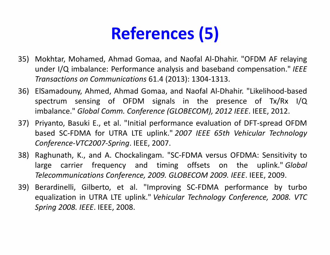
References (5)35) Mokhtar, Mohamed, Ahmad Gomaa, and Naofal Al-Dhahir. "OFDM AF relaying under I/Q imbalance: Performance analysis and baseband compensation." IEEE Transactions on Communications 61.4 (2013): 1304-1313.36) ElSamadouny, Ahmed, Ahmad Gomaa, and Naofal Al-Dhahir. "Likelihood-based spectrum sensing of OFDM signals in the presence of Tx/Rx I/Q imbalance." Global Comm. Conference (GLOBECOM), 2012 IEEE. IEEE, 2012.37) Priyanto, Basuki E., et al. "Initial performance evaluation of DFT-spread OFDM 37) Priyanto, Basuki E., et al. "Initial performance evaluation of DFT-spread OFDM based SC-FDMA for UTRA LTE uplink." 2007 IEEE 65th Vehicular Technology Conference-VTC2007-Spring. IEEE, 2007.38) Raghunath, K., and A. Chockalingam. "SC-FDMA versus OFDMA: Sensitivity to large carrier frequency and timing offsets on the uplink." Global Telecommunications Conference, 2009. GLOBECOM 2009. IEEE. IEEE, 2009.39) Berardinelli, Gilberto, et al. "Improving SC-FDMA performance by turbo equalization in UTRA LTE uplink." Vehicular Technology Conference, 2008. VTC Spring 2008. IEEE. IEEE, 2008.

40) Yoshida, Yuki, et al. "Analysis and compensation of transmitter IQ imbalances in OFDMA and SC-FDMA systems." IEEE Trans on Signal Processing 57.8 (2009): 3119-3129.41) Tarighat, Alireza, Rahim Bagheri, and Ali H. Sayed. "Compensation schemes and performance analysis of IQ imbalances in OFDM receivers." IEEE Transactions on Signal Processing 53.8 (2005): 3257-3268.42) Tarighat, Alireza, and Ali H. Sayed. "Joint compensation of
References (6)
42) Tarighat, Alireza, and Ali H. Sayed. "Joint compensation of transmitter and receiver impairments in OFDM systems." IEEE Transactions on Wireless Communications 6.1 (2007): 240-247.43) Zou, Qiyue, Alireza Tarighat, and Ali H. Sayed. "Compensation of phase noise in OFDM wireless systems." IEEE Transactions on Signal Processing 55.11 (2007): 5407-5424.

Thank You!


![Digital Modulation Lectures 1. Change which part of the Carrier? Carrier: A sin[ t + ] A = const = const = const Amplitude modulation (AM) A =](https://img.pdfslide.us/doc/110x75/56649d205503460f949f4f44/digital-modulation-lectures-1-change-which-part-of-the-carrier-carrier-a.jpg)