Embed Size (px)
DESCRIPTION
Metal Forming Practice
Citation preview

Heinz Tschaetsch
Metal Forming Practise
Heinz Tschaetsch
Metal FormingPractiseProcesses – Machines – Tools
Translated by Anne Koth
123
Author:
Professor Dr.-Ing. e. h. Heinz TschaetschPaul-Gerhardt-Str. 2501309 Dresden, Germany
andKaiserplatz 2a83435 Bad Reichenhall, Germany
Translator:
Anne KothAllsprach-ÜbersetzungsbüroWilthener Str. 6a01324 Dresden, Germany
Originally German edition published by Vieweg Verlag, Wiesbaden 2005
Library of Congress Control Number: 2006926219
ISBN-10 3-540-33216-2 Springer Berlin Heidelberg New YorkISBN-13 978-3-540-33216-9 Springer Berlin Heidelberg New York
This work is subject to copyright. All rights are reserved, whether the whole or part of the material is concerned,specifically the rights of translation, reprinting, reuse of illustrations, recitation, broadcasting, reproduction onmicrofilm or in any other way, and storage in data banks. Duplication of this publication or parts thereof ispermitted only under the provisions of the German Copyright Law of September 9, 1965, in its current version,and permission for use must always be obtained from Springer. Violations are liable for prosecution under theGerman Copyright Law.
Springer is a part of Springer Science+Business Media
springer.com
© Springer-Verlag Berlin Heidelberg 2006Printed in Germany
The use of general descriptive names, registered names, trademarks, etc. in this publication does not imply, even inthe absence of a specific statement, that such names are exempt from the relevant protective laws and regulationsand therefore free for general use.
Cover design: Erich Kirchner, HeidelbergProduction: LE-TEX Jelonek, Schmidt & Vöckler GbR, Leipzig
Printed on acid-free paper 62/3100/YL - 5 4 3 2 1 0
Preface
The book “Metal Forming”, a translation of the eighth revised edition of “Umformtechnik” in German, describes the latest technology in the sector of metal forming. Part I covers metal forming and shearing processes. It describes the main features of these processes, the tooling required and fields of application. Practical examples show how to cal-culate the forces involved in forming and the strain energy. Part II describes forming machines and shows how to calculate their parameters. This section also introduces flexible manufacturing systems in metal forming and the handling systems required for automation (automatic tool changing and workpiece conveyor systems). Part III includes tables and flow diagrams with figures needed to calculate forming forces and strain energy. These production units are automated as much as possible using modern CNC engineering to reduce non-productive time and changeover time, and thus also manufacturing costs. Along-side these economic advantages, however, another important reason for using metal working processes is their technical advantages, such as:
material savings optimal grain direction work hardening with cold forming.
This book runs through all the main metal forming and shearing processes and the tooling and machines they involve. Incremental sheet forming was recently added in Chapter 15.4.
For engineers on the shop floor, this book is intended as an easily-navigable reference work. Students can use this book for reference, saving them time making notes in the lecture theatre so that they can pay better attention to the lecture.
I would particularly like to thank my colleague, Prof. Jochen Dietrich, Ph.D.eng. h.c., lecturer in production processes and CNC engineering at Dresden University of Applied Sciences, Germany (Hochschule für Technik und Wirtschaft), for his involvement as co-author from the 6th edition.
Thanks also to Dr. Mauerman of the Fraunhofer Institute for Machine Tools and Forming Technology, Chemnitz, Germany (Institut für Werkzeugmaschinen und Umformtechink), for his collaboration on the 7th edition of the book.
Bad Reichenhall and Dresden, November 2005 Heinz Tschätsch
Contents
Preface ................................................................................................................................ V
Terms, symbols and units ................................................................................................. 1
Part I Metal forming and shearing processes ................................................................. 3
1 Types of production processes .............................................................................. 5
2 Terms and parameters of metal forming ............................................................. 72.1 Plastic (permanent) deformation ............................................................................... 7 2.2 Flow stress ................................................................................................................ 82.3 Deformation resistance.............................................................................................. 102.4 Deformability ............................................................................................................ 112.5 Degree of deformation and principal strain .............................................................. 11 2.6 Strain rate .................................................................................................................. 14 2.7 Exercise..................................................................................................................... 14
3 Surface treatment ................................................................................................... 153.1 Cold bulk forming..................................................................................................... 15 3.2 Cold sheet forming.................................................................................................... 16 3.3 Hot forming............................................................................................................... 173.4 Exercise..................................................................................................................... 17
4 Upset forging .......................................................................................................... 184.1 Definition .................................................................................................................. 18 4.2 Application................................................................................................................ 18 4.3 Starting stock ............................................................................................................ 184.4 Permissible deformations .......................................................................................... 19 4.5 Upsetting force.......................................................................................................... 234.6 Upsetting work.......................................................................................................... 234.7 Upsetting tooling....................................................................................................... 244.8 Achievable precision................................................................................................. 26 4.9 Defects in upset forging ............................................................................................ 27 4.10 Example calculations ................................................................................................ 27 4.11 Exercise..................................................................................................................... 32
5 Extrusion ................................................................................................................. 33 5.1 Definition .................................................................................................................. 33 5.2 Application of the process......................................................................................... 33 5.3 Types of extrusion process........................................................................................ 34 5.4 Starting stock ............................................................................................................ 355.5 Principal strain .......................................................................................................... 355.6 Calculation of force and mechanical work................................................................ 36 5.7 Extrusion tooling....................................................................................................... 385.8 Reinforcement calculation for single-reinforced dies.................................................... 39 5.9 Achievable precision ................................................................................................ 42 5.10 Defects during extrusion .......................................................................................... 43
VIII Contents
5.11 Sequence of operations diagram .............................................................................. 43 5.12 Example calculations ................................................................................................ 44 5.13 Shape classification .................................................................................................. 495.14 Exercise ..................................................................................................................... 55
6 Thread and gear rolling ......................................................................................... 56 6.1 Types of process ....................................................................................................... 566.2 Application of the processes .................................................................................... 58 6.3 Advantages of thread rolling .................................................................................... 59 6.4 Establishing the initial diameter ............................................................................... 60 6.5 Rolling speeds with cylindrical dies ......................................................................... 61 6.6 Rolling dies .............................................................................................................. 61 6.7 Example..................................................................................................................... 63 6.8 Thread rolling machines ........................................................................................... 64 6.9 Exercise ..................................................................................................................... 68 6.10 Processes and machines for rolling gears ................................................................. 69
7 Cold hubbing .......................................................................................................... 77 7.1 Definition ................................................................................................................. 77 7.2 Application of the process ........................................................................................ 77 7.3 Permissible deformations ......................................................................................... 78 7.4 Calculation of force and mechanical work ............................................................... 78 7.5 Materials which can be hubbed ................................................................................ 79 7.6 Hubbing speed .......................................................................................................... 807.7 Lubrication during hubbing ...................................................................................... 80 7.8 Characteristics of the workpieces to be hubbed ....................................................... 80 7.9 Hubbing tooling ....................................................................................................... 81 7.10 Advantages of cold hubbing ..................................................................................... 82 7.11 Defects during cold hubbing .................................................................................... 83 7.12 Machines for cold hubbing ....................................................................................... 83 7.13 Example calculations ................................................................................................ 84 7.14 Exercise ..................................................................................................................... 85
8 Coining (stamping) ................................................................................................. 86 8.1 Definition ................................................................................................................. 86 8.2 Types and applications of coining processes ........................................................... 86 8.3 Calculation of force and mechanical work ............................................................... 87 8.4 Tooling ..................................................................................................................... 88 8.5 Defects during coining ............................................................................................. 89 8.6 Example .................................................................................................................... 89 8.7 Exercise .................................................................................................................... 90
9 Ironing (wall ironing) ............................................................................................. 91 9.1 Definition ................................................................................................................. 91 9.2 Application of the process ........................................................................................ 91 9.3 Starting stock ............................................................................................................ 91 9.4 Principal strain ......................................................................................................... 919.5 Calculation of force and mechanical work ............................................................... 93 9.6 Example .................................................................................................................... 93 9.7 Exercise ..................................................................................................................... 94
Contents IX
10 Wire drawing .......................................................................................................... 95 10.1 Definition ................................................................................................................. 95 10.2 Application ............................................................................................................... 95 10.3 Starting stock ........................................................................................................... 96 10.4 Principal strain ......................................................................................................... 96 10.5 Permissible deformations ......................................................................................... 96 10.6 Drawing force .......................................................................................................... 9710.7 Drawing speeds ........................................................................................................ 9710.8 Drive power ............................................................................................................. 9910.9 Drawing tooling ....................................................................................................... 10010.10 Example ................................................................................................................... 102 10.11 Exercise..................................................................................................................... 104
11 Tube drawing .......................................................................................................... 105 11.1 Definition ................................................................................................................. 105 11.2 Tube drawing processes ........................................................................................... 105 11.3 Principal strain and drawing force ........................................................................... 106 11.4 Drawing tooling ....................................................................................................... 10711.5 Example ................................................................................................................... 108 11.6 Exercise..................................................................................................................... 108
12 Extrusion ................................................................................................................. 109 12.1 Definition ................................................................................................................. 109 12.2 Application ............................................................................................................... 109 12.3 Starting stock ........................................................................................................... 110 12.4 The extrusion process ............................................................................................... 110 12.5 Principal strain ......................................................................................................... 113 12.6 Strain rates during extrusion .................................................................................... 113 12.7 Extrusion force ......................................................................................................... 11412.8 Mechanical work ...................................................................................................... 11612.9 Tooling ..................................................................................................................... 118 12.10 Extrusion presses ..................................................................................................... 12012.11 Example ................................................................................................................... 121 12.12 Exercise..................................................................................................................... 122
13 Impression-die forging (closed-die forging) ......................................................... 123 13.1 Definition ................................................................................................................. 123 13.2 Starting stock ........................................................................................................... 123 13.3 Types and application of the process ....................................................................... 124 13.4 Processes in the forging die ..................................................................................... 126 13.5 Calculation of force and mechanical work ............................................................... 127 13.6 Tooling ..................................................................................................................... 132 13.7 Design of impression-die forgings ........................................................................... 136 13.8 Achievable precision ................................................................................................ 137 13.9 Example ................................................................................................................... 137 13.10 Exercise..................................................................................................................... 139
14 Deep drawing .......................................................................................................... 141 14.1 Definition ................................................................................................................. 141 14.2 Application of the process ........................................................................................ 141
X Contents
14.3 Forming process and stress distribution ................................................................... 142 14.4 Starting stock ............................................................................................................ 143 14.5 Permissible deformation ........................................................................................... 150 14.6 Deep drawing steps .................................................................................................. 152 14.7 Calculating the drawing force .................................................................................. 154 14.8 Blank holder force .................................................................................................... 15514.9 Drawing work .......................................................................................................... 15614.10 Drawing tooling ....................................................................................................... 15814.11 Achievable precision ................................................................................................ 16614.12 Defects during deep drawing ................................................................................... 167 14.13 Example .................................................................................................................... 169 14.14 Hydromechanical deep drawing ............................................................................... 172 14.15 Sheet hydroforming .................................................................................................. 17414.16 Tube hydroforming .................................................................................................. 179 14.17 Exercise ..................................................................................................................... 184
15 Deep drawing without a blank holder; metal spinning ....................................... 185 15.1 Deep drawing without a blank holder ...................................................................... 185 15.2 Metal spinning .......................................................................................................... 18615.3 Exercise ..................................................................................................................... 192 15.4 Incremental sheet forming ........................................................................................ 193
16 Bending ................................................................................................................... 194 16.1 Definition ................................................................................................................. 194 16.2 Application of the process ........................................................................................ 194 16.3 The bending process ................................................................................................. 194 16.4 Limits of bending deformation ................................................................................. 195 16.5 Spring-back .............................................................................................................. 197 16.6 Determining the blank length ................................................................................... 198 16.7 Bending force ........................................................................................................... 19916.8 Bending work ........................................................................................................... 20116.9 Bending tooling ........................................................................................................ 20316.10 Bending defects ........................................................................................................ 20416.11 Example .................................................................................................................... 204 16.12 Bending machines .................................................................................................... 20516.13 Exercise ..................................................................................................................... 211
17 Embossing ............................................................................................................... 212 17.1 Definition ................................................................................................................. 212 17.2 Application of the process ........................................................................................ 212 17.3 Calculation of force and mechanical work ............................................................... 213 17.4 Embossing tooling .................................................................................................... 21617.5 Embossing defects .................................................................................................... 21717.6 Example .................................................................................................................... 217 17.7 Exercise ..................................................................................................................... 217
18 Shearing .................................................................................................................. 218 18.1 Definition ................................................................................................................. 218 18.2 Shearing process flow .............................................................................................. 218 18.3 Types of shearing process ........................................................................................ 219
Contents XI
18.4 Permissible deformation ........................................................................................... 220 18.5 Calculation of force and mechanical work ............................................................... 220 18.6 Resultant line of action ............................................................................................ 222 18.7 Break clearance ........................................................................................................ 22518.8 Web and rim thickness ............................................................................................. 227 18.9 Achievable precision ................................................................................................ 228 18.10 Shearing tooling ....................................................................................................... 22918.11 Example ................................................................................................................... 238 18.12 Exercise..................................................................................................................... 240
19 Fine blanking (precision blanking) ....................................................................... 241 19.1 Definition ................................................................................................................. 241 19.2 Fields of application ................................................................................................. 24119.3 Shearing process flow .............................................................................................. 241 19.4 Fine blanking tooling design .................................................................................... 242 19.5 Break clearance ........................................................................................................ 24219.6 Forces during fine blanking ..................................................................................... 243 19.7 Fine blanking presses ............................................................................................... 244 19.8 Exercise..................................................................................................................... 246 19.9 Laser cutters ............................................................................................................. 247
20 Joining by forming ................................................................................................. 249 20.1 Clinching .................................................................................................................. 250 20.2 Punch riveting .......................................................................................................... 25420.3 Self-piercing riveting with semi-tubular rivets ........................................................ 257
Part II Presses
21 Types of press ......................................................................................................... 262 21.1 Presses controlled by work ...................................................................................... 262 21.2 Presses controlled by the ram path ........................................................................... 262 21.3 Presses controlled by force ...................................................................................... 263 21.4 Exercise..................................................................................................................... 263
22 Hammers ................................................................................................................. 264 22.1 Columns and frames ................................................................................................. 264 22.2 Types of hammer ..................................................................................................... 264 22.3 Constructional design and calculation of impact energy .......................................... 266 22.4 Fields of application for hammers ............................................................................ 273 22.5 Example ................................................................................................................... 274 22.6 Exercise..................................................................................................................... 274
23 Screw presses .......................................................................................................... 275 23.1 Forms of structural design ........................................................................................ 275 23.2 Functions of the individual styles of construction ................................................... 276 23.3 Calculating the parameters for screw presses .......................................................... 287 23.4 Advantages of screw presses ............................................................................................ 29123.5 Typical fields of application of screw presses ......................................................... 291 23.6 Examples .................................................................................................................. 292 23.7 Exercise..................................................................................................................... 294
XII Contents
24 Eccentric and crank presses .................................................................................. 295 24.1 Types of these presses .............................................................................................. 295 24.2 Press frame materials ............................................................................................... 298 24.3 Frame deflection and deflection energy ................................................................... 299 24.4 Eccentric and crank press drives .............................................................................. 300 24.5 Calculating the parameters ....................................................................................... 306 24.6 Example .................................................................................................................... 310 24.7 Application of eccentric and crank presses .............................................................. 312 24.8 Exercise ..................................................................................................................... 312
25 Knuckle-joint and toggle presses .......................................................................... 313 25.1 Single-point knuckle-joint presses ........................................................................... 313 25.2 Toggle presses – modified knuckle-joint presses ..................................................... 314 25.3 Horizontal knuckle-joint and toggle presses ............................................................ 317 25.4 Exercise ..................................................................................................................... 317
26 Hydraulic presses ................................................................................................... 318 26.1 Hydraulic press drives .............................................................................................. 318 26.2 Example..................................................................................................................... 320 26.3 Advantages of hydraulic presses .............................................................................. 321 26.4 Practical application of hydraulic presses ................................................................ 321 26.5 Exercise ..................................................................................................................... 324
27 Special-purpose presses ......................................................................................... 325 27.1 Deep drawing transfer presses ................................................................................. 325 27.2 Transfer presses for bulk forming ............................................................................ 331 27.3 Automatic punching presses ..................................................................................... 339 27.4 Exercise ..................................................................................................................... 344
28 Workpiece and stock feed systems ........................................................................ 345 28.1 Feed devices for piercing or blanking operations .................................................... 345 28.2 Transport devices in deep drawing transfer presses ................................................. 346 28.3 Transport devices for transfer presses for bulk forming .......................................... 347 28.4 Feed devices to supply round blanks ........................................................................ 348 28.5 Feed devices to convey single workpieces in steps .................................................. 348 28.6 Feed devices to supply forging presses .................................................................... 349 28.7 Exercise ..................................................................................................................... 349
29 Future developments in metal forming presses and tool changing systems ...... 351 29.1 Flexible manufacturing systems ............................................................................... 351 29.2 Automatic tool change systems ................................................................................ 362
Part III Tables ................................................................................................................... 367
Bibliography ....................................................................................................................... 401
Index ................................................................................................................................... 403

Terms, symbols and units
Term Symbol Unit (selection)
Work, mechanical W Nm
Force (force of pressure) F N
Drawing force Fdr N
Blank holder force FBH N
Velocity m/s, m/min
Strain rate s–1
Pressure p Pa, bar
Shear stress N/mm2
Tensile stress R, N/mm2
Tensile strength Rm N/mm2
Yield strength Re N/mm2
Elastic limit RP0.2 N/mm2
Elongation m/m, %
Flow stress kstr N/mm2
Flow stress before forming (cold forming) kstr0 N/mm2
Flow stress after forming (cold forming) kstr1 N/mm2
Resistance to flow pfl N/mm2
Deformation resistance kr N/mm2
Modulus of elasticity E N/mm2
Density t/m3, kg/dm3, g/cm3
Blank length before forming h0, l0 m, mm
Blank length after forming h1, l1 m, mm
Area A m2, mm2
Area before forming A0 m2, mm2
Area after forming A1 m2, mm2
Volume V m3, mm3
Forming temperature T K, ºC
Coefficient of friction –
Efficiency –

2 Terms, symbols and units
Term Symbol Unit (selection)
Deformation efficiency F –
Impact effect (with hammers) i –
Power P Nm/s, W
Acceleration a, g m/s2
Press strokes per minute n min–1, s–1
Stroke length H, h m, mm
Mass moment of inertia Id, kgm2
Mass m kg
Angular velocity s–1
Moment M Nm, J
Tangential force (with crank presses) Tp N
Crank angle (with crank presses) º


3
Part I: Metal forming and shearing processes
1 Types of manufacturing process
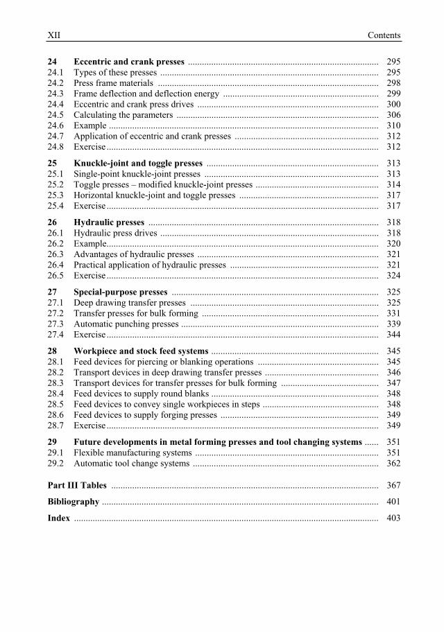
The manufacturing processes are subdivided into six main groups.
Fig 1.1 Types of production process
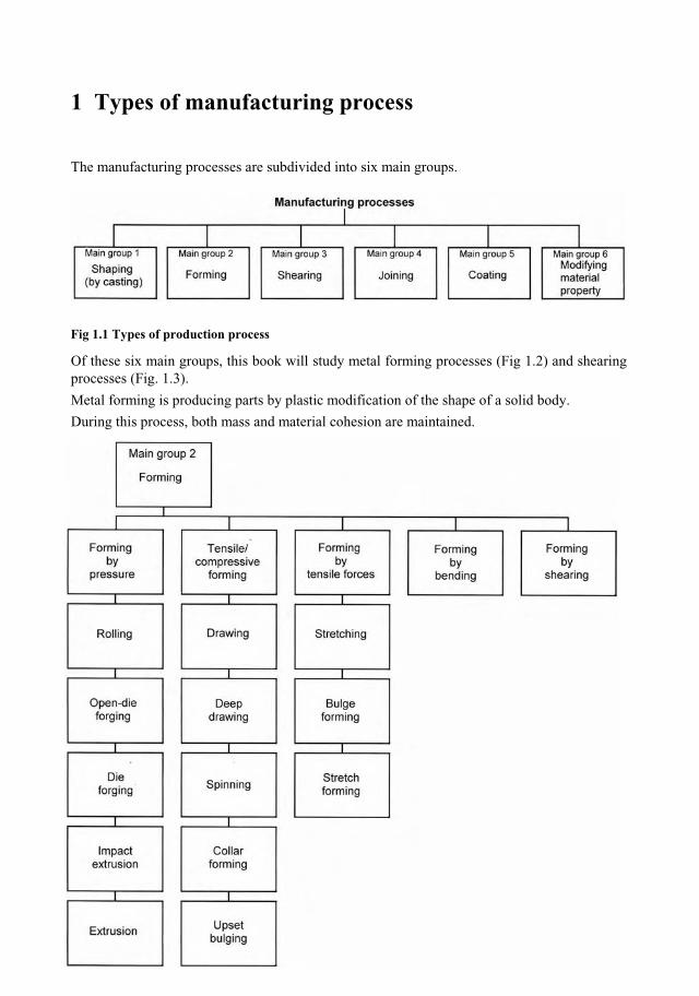
Of these six main groups, this book will study metal forming processes (Fig 1.2) and shearing processes (Fig. 1.3). Metal forming is producing parts by plastic modification of the shape of a solid body. During this process, both mass and material cohesion are maintained.
6 1 Types of manufacturing process
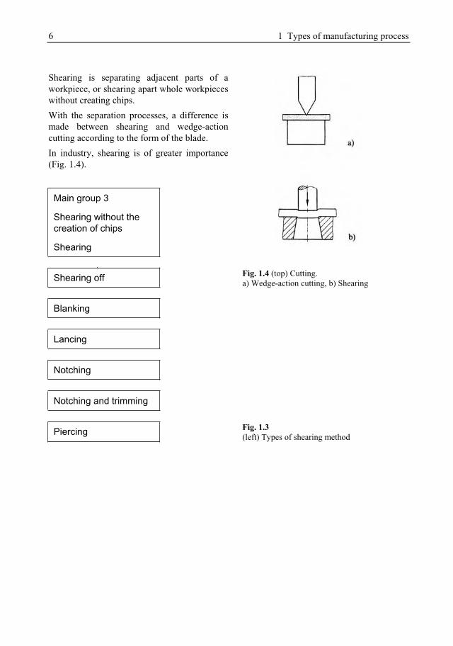
Shearing is separating adjacent parts of a workpiece, or shearing apart whole workpieceswithout creating chips. With the separation processes, a difference is made between shearing and wedge-action cutting according to the form of the blade. In industry, shearing is of greater importance (Fig. 1.4).
Main group 3
Shearing without the creation of chips
Shearing
Shearing off
Blanking
Fig. 1.4 (top) Cutting. a) Wedge-action cutting, b) Shearing
Lancing
Notching
Notching and trimming
Piercing Fig. 1.3 (left) Types of shearing method
2 Terms and parameters of metal forming
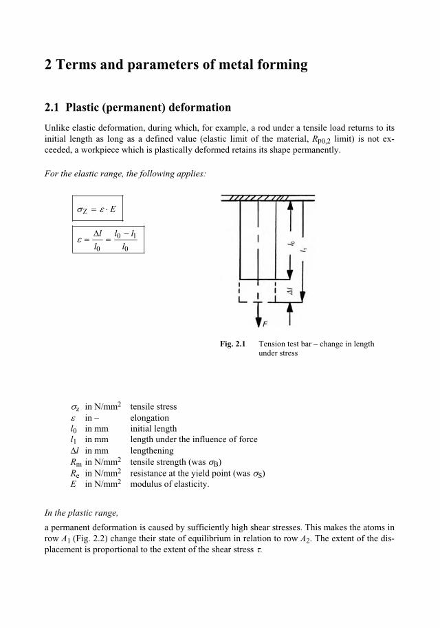
2.1 Plastic (permanent) deformation Unlike elastic deformation, during which, for example, a rod under a tensile load returns to its initial length as long as a defined value (elastic limit of the material, Rp0,2 limit) is not ex-ceeded, a workpiece which is plastically deformed retains its shape permanently.
For the elastic range, the following applies:
Z
0 1
0 0
E
l l ll l
Fig. 2.1 Tension test bar – change in length under stress
z in N/mm2 tensile stress in – elongation
l0 in mm initial length l1 in mm length under the influence of force
l in mm lengthening Rm in N/mm2 tensile strength (was B)Re in N/mm2 resistance at the yield point (was S)E in N/mm2 modulus of elasticity.
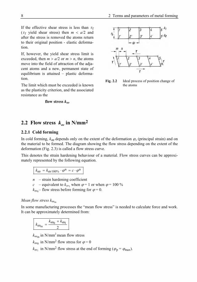
In the plastic range,a permanent deformation is caused by sufficiently high shear stresses. This makes the atoms in row A1 (Fig. 2.2) change their state of equilibrium in relation to row A2. The extent of the dis-placement is proportional to the extent of the shear stress .
8 2 Terms and parameters of metal forming
If the effective shear stress is less than f( f yield shear stress) then m a/2 and after the stress is removed the atoms return to their original position - elastic deforma-tion. If, however, the yield shear stress limit is exceeded, then m a/2 or m n, the atoms move into the field of attraction of the adja-cent atoms and a new, permanent state of equilibrium is attained – plastic deforma-tion. The limit which must be exceeded is known as the plasticity criterion, and the associated resistance as the
flow stress kstr
Fig. 2.2 Ideal process of position change of the atoms
2.2 Flow stress kstr in N/mm2
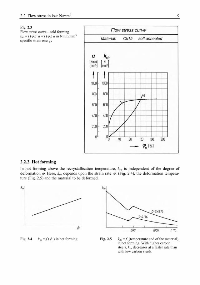
2.2.1 Cold forming In cold forming, kstr depends only on the extent of the deformation p (principal strain) and on the material to be formed. The diagram showing the flow stress depending on the extent of the deformation (Fig. 2.3) is called a flow stress curve. This denotes the strain hardening behaviour of a material. Flow stress curves can be approxi-mately represented by the following equation.
n nstr str100%k k c
n – strain hardening coefficient c – equivalent to kstr1 when = 1 or when = 100 % kstr0 – flow stress before forming for = 0.
Mean flow stress kstrm
In some manufacturing processes the “mean flow stress” is needed to calculate force and work. It can be approximately determined from:
0 1m
str strstr 2
k kk
kstrm in N/mm2 mean flow stress kstr0 in N/mm2 flow stress for = 0 kstr1 in N/mm2 flow stress at the end of forming ( p = max).
2.2 Flow stress in kstr N/mm2 9
Fig. 2.3 Flow stress curve - cold forming kstr = f ( p) a = f ( p) a in Nmm/mm3
specific strain energy
2.2.2 Hot forming In hot forming above the recrystallisation temperature, kstr is independent of the degree of deformation . Here, kstr depends upon the strain rate (Fig. 2.4), the deformation tempera-ture (Fig. 2.5) and the material to be deformed.
Fig. 2.4 kstr = f ( ) in hot forming Fig. 2.5 kstr = f (temperature and of the material) in hot forming. With higher carbon steels, kstr decreases at a faster rate than with low carbon steels.
10 2 Terms and parameters of metal forming
At high strain rates kstr rises during hot forming since the cohesion-reducing processes which arise due to recrystallisation no longer take place completely.
2.2.3 Calculation of the flow stress kstrsh for semi-hot forming
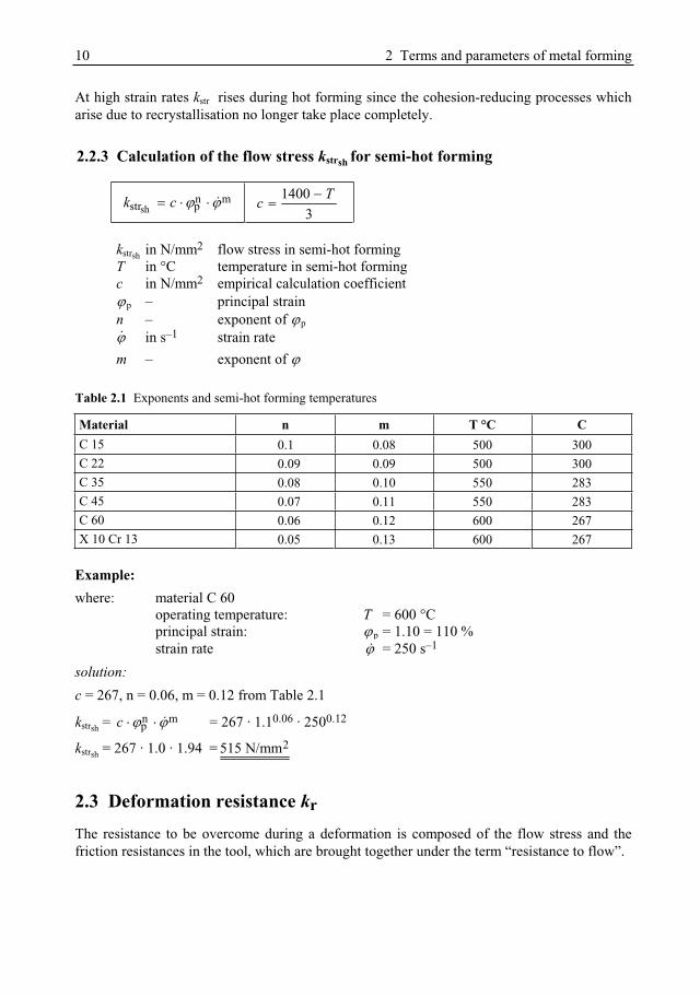
shn mstr pk c 1400
3Tc
kstrsh in N/mm2 flow stress in semi-hot forming T in °C temperature in semi-hot forming c in N/mm2 empirical calculation coefficient
p – principal strain n – exponent of p
in s–1 strain rate m – exponent of
Table 2.1 Exponents and semi-hot forming temperatures
Material n m T °C CC 15 0.1 0.08 500 300C 22 0.09 0.09 500 300C 35 0.08 0.10 550 283C 45 0.07 0.11 550 283C 60 0.06 0.12 600 267X 10 Cr 13 0.05 0.13 600 267
Example: where: material C 60 operating temperature: T = 600 °C principal strain: p = 1.10 = 110 % strain rate = 250 s–1
solution: c = 267, n = 0.06, m = 0.12 from Table 2.1
kstrsh = n mpc = 267 · 1.10.06 · 2500.12
kstrsh = 267 · 1.0 · 1.94 = 2515 N/mm
2.3 Deformation resistance kr
The resistance to be overcome during a deformation is composed of the flow stress and the friction resistances in the tool, which are brought together under the term “resistance to flow”.

2.4 Deformability 11
frr strk k p
kr in N/mm2 deformation resistance kstr in N/mm2 flow stress pfl in N/mm2 resistance to flow
The resistance to flow pfl can be calculated mathematically for rotationally symmetric pieces.
11
fl str1
13
dp kh
From this it follows that for the deformation resistance kw
11
r str1
113
dk kh
kstrl in N/mm2 flow stress at the end of forming d0 in mm diameter before forming h0 in mm height before forming (Fig. 4.6)
– coefficient of friction ( = 0.15) d1 in mm diameter after forming h1 in mm height after forming
F – deformation efficiency.
For asymmetric pieces, which can only be studied mathematically to a limited extent, the de-formation resistance is determined with the help of the deformation efficiency.
1strr
F.
kk
2.4 Deformability This means the ability of a material to be deformed. It depends upon:
2.4.1 Chemical composition In steels, for example, the cold deformability depends on the C content, the components of the alloy (Ni, Cr, Va, Mo, Mn) and the phosphor content. The higher the C content, the P content and the alloy components, the lower the deformability is.
2.4.2 Crystalline structure Here, the grain size and above all the pearlite structure are important. – Grain size Steels should be as fine-grained as possible, since in steels with small to medium grain size, the crystallites are easier to displace on the crystallite slip planes.
12 2 Terms and parameters of metal forming
– Pearlite structure Pearlite is the carbon carrier in the steel. It is difficult to deform. For this reason it is important that the pearlite is equally distributed in the ferritic matrix, which is easy to cold form.
2.4.3 Heat treatment
An equally-distributed structure is achieved by normalising (above Ac3) and fast cooling. The resulting hardness is cancelled out by subsequent soft annealing (around Ac1). Note: only soft annealed material can be cold formed.
2.5 Degree of deformation and principal strain
2.5.1 Bulk forming process
The measure of the extent of a deformation is the degree of deformation. The calculation is generally made from the relation between an indefinitely small measurement difference, dx,and an existing measurement x. By integrating it into the limits x0 to x1 this produces
1
0
1x
0
d ln .x
x
x xx x
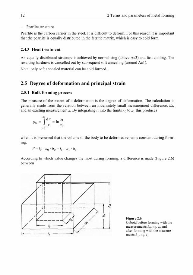
when it is presumed that the volume of the body to be deformed remains constant during form-ing.
V = l0 · w0 · h0 = l1 · w1 · h1.
According to which value changes the most during forming, a difference is made (Figure 2.6) between
Figure 2.6 Cuboid before forming with the measurements h0, w0, l0 and after forming with the measure-ments h1, w1, l1
2.5 Degree of deformation and principal strain 13
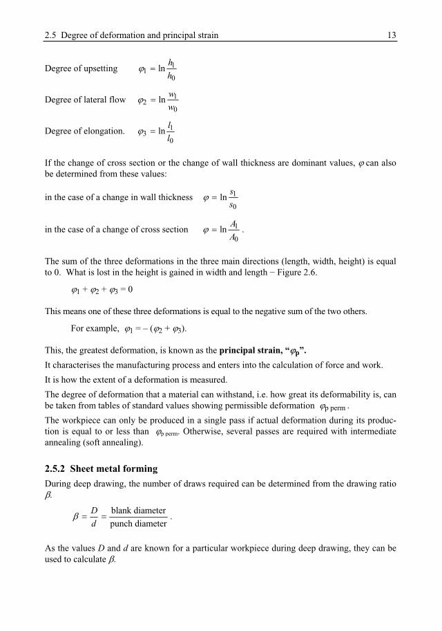
Degree of upsetting 11
0ln h
h
Degree of lateral flow 12
0ln w
w
Degree of elongation. 13
0ln l
l
If the change of cross section or the change of wall thickness are dominant values, can also be determined from these values:
in the case of a change in wall thickness 1
0ln s
s
in the case of a change of cross section 1
0ln A
A.
The sum of the three deformations in the three main directions (length, width, height) is equal to 0. What is lost in the height is gained in width and length Figure 2.6.
1 + 2 + 3 = 0
This means one of these three deformations is equal to the negative sum of the two others.
For example, 1 = – ( 2 + 3).
This, the greatest deformation, is known as the principal strain, “ p”.It characterises the manufacturing process and enters into the calculation of force and work. It is how the extent of a deformation is measured. The degree of deformation that a material can withstand, i.e. how great its deformability is, can be taken from tables of standard values showing permissible deformation p perm .The workpiece can only be produced in a single pass if actual deformation during its produc-tion is equal to or less than p perm. Otherwise, several passes are required with intermediate annealing (soft annealing).
2.5.2 Sheet metal forming During deep drawing, the number of draws required can be determined from the drawing ratio
.
blank diameterpunch diameter
Dd
.
As the values D and d are known for a particular workpiece during deep drawing, they can be used to calculate

14 2 Terms and parameters of metal forming
Here, tables of standard values (see the chapter on deep drawing) are once more used to find the permissible drawing ratio perm; it is then compared with the calculated drawing ratio. The workpiece can only be produced in a single phase if is equal to or less than perm. Otherwise, several passes are necessary.
2.6 Strain rate If a deformation is carried out in the time t, this results in an average strain rate of:
mwt
wm in %/s mean strain rate in % degree of deformation
t in s deformation time
It may, however, also be determined by the ram / slide velocity and the initial height of the workpiece.
0
vh
in s–1 strain rate v in m/s velocity of the ram / slide h0 in s height of the blank.
2.7 Exercise on Chapter 2 1. Which conditions must be met in order to achieve plastic (permanent) deformation? 2. What is meant by “flow stress” kstr?3. How can the flow stress value be ascertained? 4. How can the mean yield stress be (approximately) calculated? 5. What influence does the forming temperature have on flow stress? 6. What influence does the strain rate have on flow stress?
a) during cold forming b) during hot forming?
7. What is meant by “cold forming”? 8. What is meant by “deformability”? 9. What factors does the deformability of a material depend upon? 10. Explain these terms:
degree of upsetting degree of lateral flow degree of elongation.
11. What is meant by “principal strain”?
3 Surface treatment
If the blanks (sections of wire or rods) were simply inserted into the moulding die and then pressed, the die would be made useless after only a few units. Galling would occur in the die because of cold welding between the workpiece and the die. As a result, burrs would form on the die which would make the pressed parts unusable. For this reason, the blanks must be care-fully prepared before pressing. This preparation, which is summed up as “surface treatment”, includes
pickling, phosphating, lubricating.
3.1 Cold bulk forming
3.1.1 Pickling
The pickling process is intended to remove oxidic coatings (rust, scale) so that the surface of the press blank is metallically clean, ready for the actual surface treatment. Diluted acids are used as a pickling agent, e.g. for steel, 10% sulphuric acid (percent by vol-ume).
3.1.2 Phosphating
If grease, oil or soap were directly applied to a metallically clean (pickled) blank as a lubricant, the lubricant would have no effect. The film of lubricant would come off during pressing and cold welding and galling would take place. Therefore a lubricant carrier coating must be applied first, forming a firm bond with the blank material. Phosphates are used as a carrier coating. Phosphating applies a non-metallic lubricant carrier, firmly bonded with the base material of the blank made of
steel (with the exception of Nirosta steels) zinc and zinc alloys aluminium and aluminium alloys.
This porous layer acts as a lubricant carrier. The lubricant diffuses into the pores and can thus no longer be rubbed off of the blank. Coating thicknesses of the applied phosphates range between 5 and 15 m.

16 3 Surface treatment
3.1.3 Lubrication
– Function of the lubricant:The lubricant is intended to:
– prevent the die and the workpiece from coming into direct contact with one another, in order to make it impossible for material to be transferred from the die to the workpiece (cold welding);
– reduce friction between the surfaces gliding against one another; – keep the heat which occurs during forming within limits.
– Lubricants for cold formingFor cold forming, the following materials can be employed as lubricants.
– Lime (liming)Liming means that the blanks are immersed in a solution of water with 8 percent lime by weight heated to 90°C. Liming can only be used for steel for small deformations.
– SoapHere, for example, solutions of hard soap are used with 4-8 percent soap by weight at 80°C and an immersion time of 2-3 minutes. Their use is appropriate when there is a medium lu-bricant requirement.
– Mineral oils (possibly with a little supplementary grease)These lubricants, available on the market as “Press Oils”, are suited to high lubricant re-quirements, above all in automatic production. As well as lubrication, they also assume a cooling function.
– Molybdenum disulphide (molycote suspensions)For lubricants on a molybdenum disulphide basis, which are suited to the highest lubrica-tion requirements,
MoS2 water suspensions
are mainly used. Immersion time ranges from 2 to 5 minutes at a temperature of 80 °C. The concentration (mean value) is around 1 : 3 (i.e. 1 part molycote, 3 parts water).
For particularly difficult deformations, higher-concentrated suspensions are also used.
3.2 Cold sheet forming As a rule pure lubricating agents such as drawing oils or drawing greases suffice for deep drawing, preventing direct contact between the die and the workpiece.

3.4 Exercise on Chapter 3 17
3.3 Hot forming (drop forging) During drop forging, sawdust and graphite suspensions are used as lubricants and anti-seize agents. Optimal results can be achieved with 4% colloidal graphite in water or light oil. With the liquid lubricants, however, attention must be paid to correct dosage. Too much suspension raises the gas pressure in the die and makes moulding difficult.
3.4 Exercise on Chapter 3 1. What is the function of the lubricant during forming? 2. Why can the blank not simply be lubricated with oil or grease during cold forming? 3. How must the blanks be pre-treated (surface treated) before a cold forming pressing proc-
ess? 4. What lubricants are used in cold forming? 5. What lubricants are used in drop forging?
4 Upset forging
4.1 Definition Upset forging is a bulk forming process where the effect of the pressure is on the longitudinal axis of the workpiece.
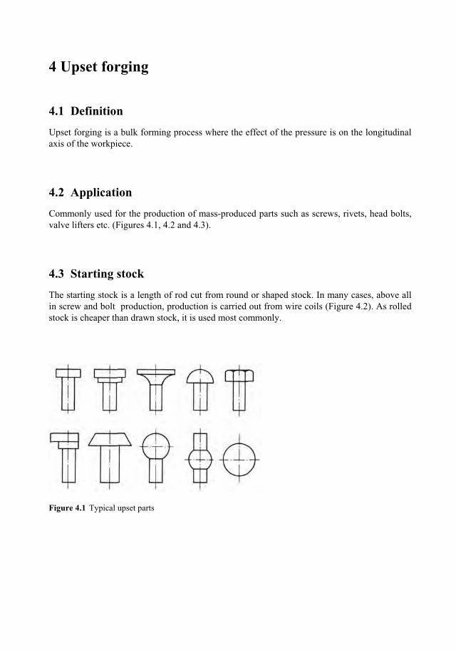
4.2 Application Commonly used for the production of mass-produced parts such as screws, rivets, head bolts, valve lifters etc. (Figures 4.1, 4.2 and 4.3).
4.3 Starting stock The starting stock is a length of rod cut from round or shaped stock. In many cases, above all in screw and bolt production, production is carried out from wire coils (Figure 4.2). As rolled stock is cheaper than drawn stock, it is used most commonly.
Figure 4.1 Typical upset parts
4.4 Permissible deformations 19
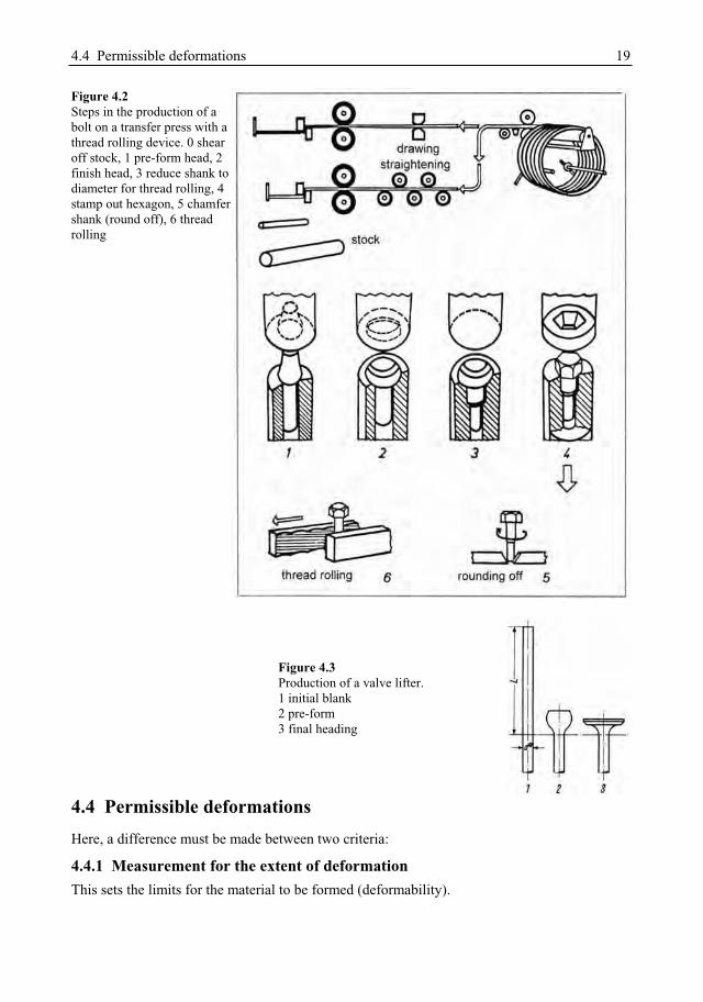
Figure 4.2 Steps in the production of a bolt on a transfer press with a thread rolling device. 0 shear off stock, 1 pre-form head, 2 finish head, 3 reduce shank to diameter for thread rolling, 4 stamp out hexagon, 5 chamfer shank (round off), 6 thread rolling
Figure 4.3 Production of a valve lifter.1 initial blank 2 pre-form 3 final heading
4.4 Permissible deformations Here, a difference must be made between two criteria:
4.4.1 Measurement for the extent of deformation This sets the limits for the material to be formed (deformability).
20 4 Upset forging
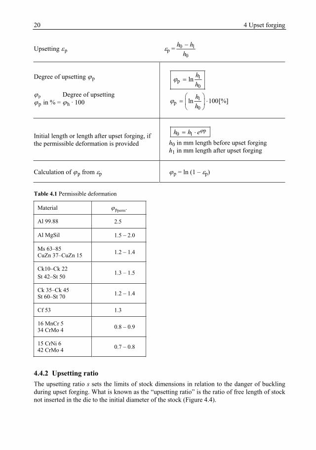
Upsetting p p = 0 1
0
h hh
Degree of upsetting p
p Degree of upsetting p in % = h · 100
1p
0ln h
h
1p
0ln 100[%]h
h
Initial length or length after upset forging, if the permissible deformation is provided
p0 1h h eh0 in mm length before upset forging h1 in mm length after upset forging
Calculation of p from p p = ln (1 – p)
Table 4.1 Permissible deformation
Material pperm.
Al 99.88 2.5
Al MgSil 1.5 – 2.0
Ms 63–85 CuZn 37–CuZn 15 1.2 – 1.4
Ck10–Ck 22 St 42–St 50 1.3 – 1.5
Ck 35–Ck 45 St 60–St 70 1.2 – 1.4
Cf 53 1.3
16 MnCr 5 34 CrMo 4 0.8 – 0.9
15 CrNi 6 42 CrMo 4 0.7 – 0.8
4.4.2 Upsetting ratio The upsetting ratio s sets the limits of stock dimensions in relation to the danger of buckling during upset forging. What is known as the “upsetting ratio” is the ratio of free length of stock not inserted in the die to the initial diameter of the stock (Figure 4.4).
4.4 Permissible deformations 21
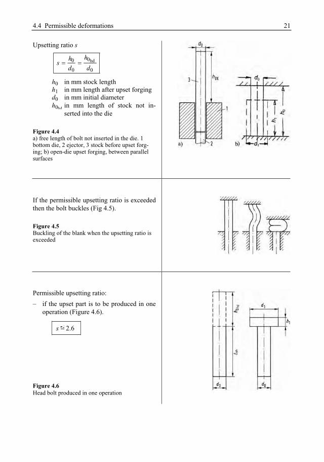
Upsetting ratio s
hd00
0 0
hhsd d
h0 in mm stock length h1 in mm length after upset forging d0 in mm initial diameter h0hd in mm length of stock not in-
serted into the die
Figure 4.4 a) free length of bolt not inserted in the die. 1 bottom die, 2 ejector, 3 stock before upset forg-ing; b) open-die upset forging, between parallel surfaces
If the permissible upsetting ratio is exceeded then the bolt buckles (Fig 4.5).
Figure 4.5 Buckling of the blank when the upsetting ratio is exceeded
Permissible upsetting ratio: – if the upset part is to be produced in one
operation (Figure 4.6).
s 2.6
Figure 4.6 Head bolt produced in one operation
22 4 Upset forging
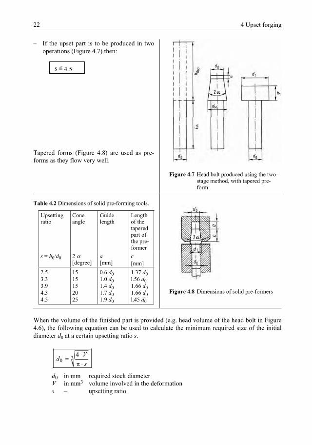
– If the upset part is to be produced in two operations (Figure 4.7) then:
Tapered forms (Figure 4.8) are used as pre-forms as they flow very well.
Figure 4.7 Head bolt produced using the two-stage method, with tapered pre-form
Table 4.2 Dimensions of solid pre-forming tools.
Upsettingratio
Coneangle
Guidelength
Lengthof the taperedpart of the pre-former
s = h0/d0 2 [degree]
a[mm]
c[mm]
2.53.33.94.34.5
1515152025
0.6 d01.0 d01.4 d01.7 d01.9 d0
1.37 d0l.56 d01.66 d01.66 d0l.45 d0
Figure 4.8 Dimensions of solid pre-formers
When the volume of the finished part is provided (e.g. head volume of the head bolt in Figure 4.6), the following equation can be used to calculate the minimum required size of the initial diameter d0 at a certain upsetting ratio s.
304 Vd
s
d0 in mm required stock diameter V in mm3 volume involved in the deformation s – upsetting ratio
s 4.5
4.6 Upset forging work 23
4.5 Upsetting force
4.5.1 For rotationally symmetric parts F in N upsetting force A1 in mm2 surface after upset forging kstr1in N/mm2 flow stress at the end of upset
forging – coefficient of friction
( = 0.1 – 0.15) d1 in mm diameter after upset forging h1 in mm height after upset forging
11
1 str1
113
dF A kh
4.5.2 For bodies of any shape
F – deformation efficiency 11 str
F
A kF
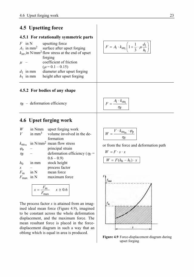
4.6 Upset forging work W in Nmm upset forging work V in mm3 volume involved in the de-
formation kstrm in N/mm2 mean flow stress
p – principal strain F – deformation efficiency ( F =
0.6 – 0.9) h0 in mm stock height x – process factor Fm in N mean force Fmax in N maximum force
m
max0.6Fx x
F
The process factor x is attained from an imag-ined ideal mean force (Figure 4.9), imagined to be constant across the whole deformation displacement, and the maximum force. The mean resultant force is placed in the force-displacement diagram in such a way that an oblong which is equal in area is produced.
mstr p
F
V kW
or from the force and deformation path W F · s · x
0 1( )W F h h x
Figure 4.9 Force-displacement diagram during upset forging
24 4 Upset forging
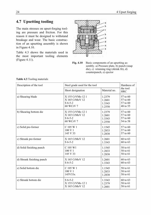
4.7 Upsetting tooling The main stresses on upset-forging tool-ing are pressure and friction. For thisreason it must be designed to withstandbreakage and wear. The basic construc-tion of an upsetting assembly is shownin Figure 4.10. Table 4.3 shows the materials used inthe most important tooling elements (Figure 4.11).
Fig. 4.10 Basic components of an upsetting as-sembly. a) Pressure plate, b) punch (snap die), c) retaining ring (shrink fit), d) counterpunch, e) ejector
Table 4.3 Tooling materials
Steel grade used for the tool Description of the tool
Short designation Material no.
Hardness of the tool HRC
a) Shearing blade X 155 CrVMo 12 1 X 165 CrMoV 12 S 6-5-2 60 WCrV 7
1.23791.26011.33431.2550
57 to 60 57 to 60 57 to 60 48 to 55
b) Shearing bottom die X 155 CrVMo 12 1 X 165 CrMoV 12 S 6-5-2 60 WCrV 7
1.23791.26011.33431.2550
57 to 60 57 to 60 57 to 60 54 to 58
c) Solid pre-former C 105 W 1 100 V 1 145 V 33
1.15451.28331.2838
57 to 60 57 to 60 57 to 60
c) Shrunk pre-former X 165 CrMoV 12 S 6-5-2
1.26011.3343
60 to 63 60 to 63
d) Solid finishing punch C 105 W1 100 V 1 145 V 33
1.15451.28331.2838
58 to 61 58 to 61 58 to 61
d) Shrunk finishing punch X 165 CrMoV 12 S 6-5-2
1.26011.3343
60 to 63 60 to 63
e) Solid bottom die C 105 W 1 100 V 1 145V33x
1.15451.28331.2838
58 to 61 58 to 61 58 to 61
e) Shrunk bottom die S 6-5-2 X 155 CrVMo 12 1 X 165 CrMoV 12
1.33431.23791.2601
60 to 63 58 to 61 58 to 61
4.7 Upsetting tooling 25
f) Retaining ring 56 NiCrMoV 7 X 40 CrMoV 5 1 X 3 NiCoMoTi 1895
1.27141.23441.2709
41 to 47 41 to 47 50 to 53
g) Ejector X 40 CrMoV 5 1 60 WCrV 7
1.23441.2550
53 to 56 55 to 58
Shearing tool: (Figure 4.11 b)
1 Bottom die S 6-5-2 1.3343 58 to 61
2 Punch 60 WCrV 7 X 155 CrVMo 12 1 X 165 CrMoV 12
1.25501.23791.2601
58 to 61 58 to 61 58 to 61
3 Ejector X 40 CrMoV 51 60 WCrV 7
1.23441.2550
53 to 56 55 to 58
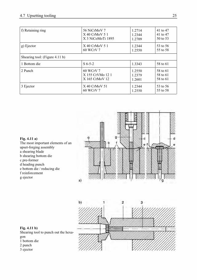
Fig. 4.11 a)The most important elements of an upset-forging assembly a shearing blade b shearing bottom die c pre-former d heading punch e bottom die / reducing die f reinforcement g ejector
Fig. 4.11 b)Shearing tool to punch out the hexa-gon1 bottom die 2 punch 3 ejector
26 4 Upset forging
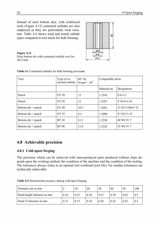
Instead of steel bottom dies, with reinforced tools (Figure 4.12) cemented carbides are also employed as they are particularly wear resis-tant. Table 4.4 shows tried and tested carbide types compared to tool steels for bulk forming.
Figure 4.12 Press bottom die with cemented carbide core for M12 bolt
Table 4.1 Cemented carbides for bulk forming processes
Tool Type of ce-mented carbide
HV 30 N/mm2 · 103
Comparable steels
Material no. Designation
Punch GT 20 13 1.3343 S 6-5-2
Punch GT 30 12 1.3207 S 10-4-3-10
Bottom die + punch GT 40 10.5 1.2601 X 165 CrMoV 12
Bottom die + punch GT 55 8.5 1.2080 X 210 Cr 12
Bottom die + punch BT 30 11.5 1.2550 60 WCrV 7
Bottom die + punch BT 40 11.0 1.2542 45 WCrV 7
4.8 Achievable precision
4.8.1 Cold upset forging
The precision which can be achieved with mass-produced parts produced without chips de-pends upon the working method, the condition of the machine and the condition of the tooling. The tolerances always relate to an optimal tool workload (tool life). Far smaller tolerances are technically achievable.
Table 4.5 Dimensional accuracy during cold upset forging
Nominal size in mm 5 10 20 30 40 50 100
Head height tolerance in mm 0.18 0.22 0.28 0.33 0.38 0.42 0.5
Head tolerance in mm 0.12 0.15 0.18 0.20 0.22 0.25 0.3
4.10 Example calculations 27
4.8.2 Hot upset forging
During hot upset forging, the diameter and height tolerances are roughly five times as high as those during cold upset forging.
4.9 Defects in upset forging
Table 4.6 Upset forging defects and their causes
Defect Cause Steps to be taken
Buckling of the shank Upsetting ratio s exceeded. Reduce s by pre-forming
Longitudinal crack in the head Die scars or surface damage in the starting material.
Check the stock for surface dam-age.
Shear cracks in the head
Internal cracks in the head
Deformability exceeded
p > perm
Reduce degree of deformation Divide forming into two opera-tions.
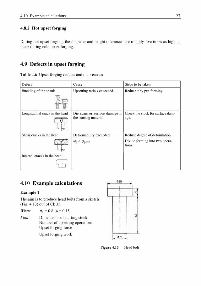
4.10 Example calculations Example 1 The aim is to produce head bolts from a sketch (Fig. 4.13) out of Ck 35. Where: F = 0.8; = 0.15 Find: Dimensions of starting stock
Number of upsetting operations Upset forging force
Upset forging work
Figure 4.13 Head bolt

28 4 Upset forging
Solution:
1. Volume of the head of the part to be produced
Vhd=2 2(30mm) 20mm4 4
d h
= 14137 mm3.An extra 1-2% are usually added to this volume to make up for melt and pickling losses. This extra percentage is left out here for simplification.
2. Determination of the initial diameter As the shank diameter is 20 mm, here the initial diameter is chosen as
d0 = 20 mm. For the initial area, this means
A0 =204
d= 314.2 mm2.
3. Initial height of the head (Figure 4.6)
h0hd =3hd20
14137 mm314.2 mm
VA
= 45 mm.
4. Blank length
L = h0hd + hsh = 45 mm + 60 mm = 105 mm. This results in the dimension of the blank:
20 × 105 long.
5. Upsetting ratio
s = hd0
0
45 mm 2.2520 mm
hd
Because s is smaller than the highest permissible value, 2.6, the workpiece can be produced in one operation from the point of view of bulging.
6. Size of principal strain
p = 1
0
20 mmln ln 0.81 81%.45 mmhd
hh

4.10 Example calculations 29
The permissible deformation from Table 1 is
p perm = 140 % Because the actual deformation based on the dimensions, p , is smaller than the permissible deformation p perm, it is also possible to produce the workpiece in one operation from the point of view of deformability.
7. Flow stress The values for kstr are taken from the flow stress curve for the material Ck 35, or from Table 1, Part III
kstr0 = 340 N/mm2 for p = 0 %,
kstr1 = 920 N/mm2 for p = 81 % ,
kstrm= 0 1str str 2340 920 630 N/ mm2 2
k k.
8. Upset forging force
F = 11
1 str1
113
dA kh
=2
2(30 mm) N 1 30 mm920 1 0.15 .
4 3 20 mmmm
F = 699082.8 N = 699 KN ,
9. Upset forging work
Example 2The aim is to produce spheres 30 mm in diameter out of 42 CrMo 4. The initial diameter is to be set in such a way that the upsetting ratio is s = 2.6. Where: F = 0.8; = 0.15. Find:1. volume of the sphere 2. blank diameter d0 for s = 2.6 3. blank dimensions 4. actual upsetting ratio 5. upset forging force 6. upset forging work

30 4 Upset forging
Solution:1. Volume of the sphere
V = 3 34 4 (15 mm)3 3
r = 14137.16 mm3.
2. Initial diameter from upsetting ratio
As material (rolled steel) in this size (19.05 ) is not commercially available, instead
d0 = 20 mm is chosen.
At the same time, this choice means that the upsetting ratio is on the safe side, as it means it goes down to less than 2.6.
3. Blank length
4. Actual upsetting ratio from the blank dimensions
s = 0
0
45 mm 2.25.20 mm
hd
Becausesactual sperm2.25 2.6,
the sphere can safely be produced from these blank dimensions without any danger of buck-ling.
5. Upsetting force
5.1 p = 1
0
30 mmln ln 0.4 40%45 mm
hh
p perm = 80 % (from Table 1), therefore possible in one operation from the point of view of deformability
5.2 Take kstr values from flow stress curve:
kstr0 = 420 N/mm2, kstr1 = 960 N/mm2

4.10 Example calculations 31
kstrm= 0str 2420 960 690 N/ mm2 2
k k
5.3 F = 11
1 str1
113
dA kh
= 2 2 1 30 mm(30 mm) 960 N/ mm 1 0.154 3 30 mm
F = 712513.2 N = 712 kN.
6. Upset forging work
W = m3 2str h
3 3F
14137.16 mm 690 N/ mm 0.410 mm /m 0.8 10 mm / m
V k
W = 4877.3 N m = 4.8 kN m
Calculation sheet: upset forging
1. Material:______________
2. d0 = 20mm, mmA
3. VolumeV = 3mm
4. h0 =0
mmVA
5. s = 0
0
hd
6. p = 0
1ln ln ln %h
h
7. kstr0 = 1 m2str str; ; N/ mmk k
8. F = 11
1 str1
113
dA kh
F = 11 0.153
F = kNN
8.1 F = 11 str3F
kN0.7 10
A k

32 4 Upset forging
9. W = mstr p6 6F 10 0.7 10
V k
W = kN m
106 = Conversion factor of N mm into kN m.
4.11 Exercise on Chapter 4
1. What is upset forging used for most commonly? 2. What is the measure of the extent of a deformation? 3. How can you find information on the permissible deformation values ? 4. How can you use deformability to check the number of operations required to produce an
upset part? 5. What else must be taken into account apart from deformability? 6. What happens if the permissible upsetting ratio is exceeded? 7. Name the most important elements of upset forging tooling. 8. What has gone wrong if shear cracks appear on the head of the upset part? 9. What steps are required to produce a hexagonal bolt?
10. Why is it cheaper to produce a bolt using the forging method shown on Page 19 than with an automatic lathe?
11. Which special forging presses are used today to produce screws and bolts? (Chap. 27.2)
5 Extrusion
5.1 Definition Extrusion is a bulk forming process in which the material is made to flow using high pressure. The deformation takes places mainly at room temperature cold extrusion as by this means plate-finished workpieces with close dimensional accuracy are obtained. The billets are only heated to forging temperature hot extrusion if extreme conditions would be necessary for cold forging (high punch force, high degree of deformation, etc). Workpieces produced in this way are of low dimensional accuracy and have rough surfaces due to scaling, requiring reworking in most cases.
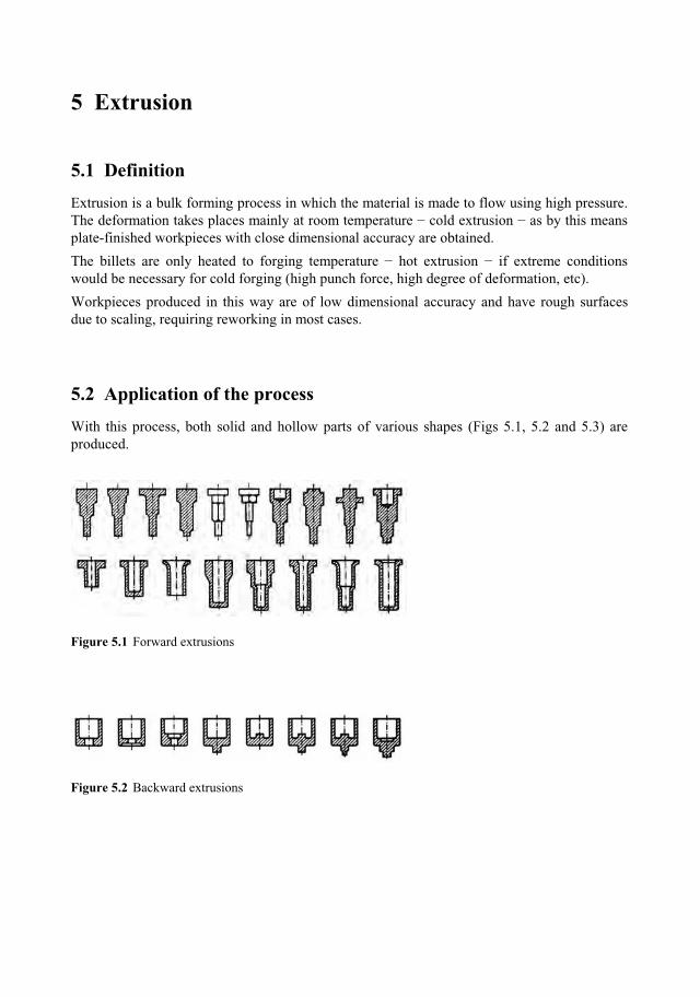
5.2 Application of the process With this process, both solid and hollow parts of various shapes (Figs 5.1, 5.2 and 5.3) are produced.
Figure 5.1 Forward extrusions
Figure 5.2 Backward extrusions
34 5 Extrusion
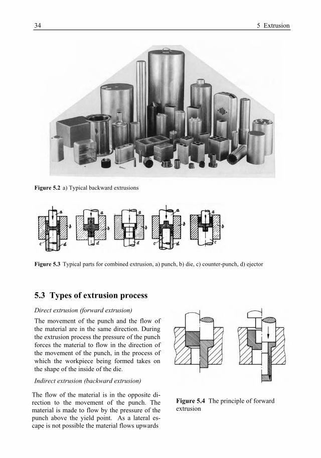
Figure 5.2 a) Typical backward extrusions
Figure 5.3 Typical parts for combined extrusion, a) punch, b) die, c) counter-punch, d) ejector
5.3 Types of extrusion process Direct extrusion (forward extrusion) The movement of the punch and the flow of the material are in the same direction. During the extrusion process the pressure of the punch forces the material to flow in the direction of the movement of the punch, in the process of which the workpiece being formed takes on the shape of the inside of the die.
Indirect extrusion (backward extrusion)
Figure 5.4 The principle of forward extrusion
The flow of the material is in the opposite di-rection to the movement of the punch. Thematerial is made to flow by the pressure of thepunch above the yield point. As a lateral es-cape is not possible the material flows upwards
5.5 Principal strain 35
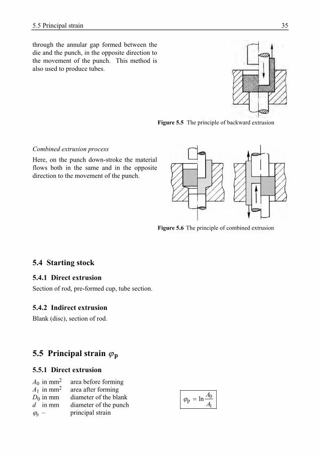
through the annular gap formed between the die and the punch, in the opposite direction to the movement of the punch. This method is also used to produce tubes.
Figure 5.5 The principle of backward extrusion
Combined extrusion processHere, on the punch down-stroke the material flows both in the same and in the opposite direction to the movement of the punch.
Figure 5.6 The principle of combined extrusion
5.4 Starting stock
5.4.1 Direct extrusion Section of rod, pre-formed cup, tube section.
5.4.2 Indirect extrusion Blank (disc), section of rod.
5.5 Principal strain p5.5 principal strain
5.5.1 Direct extrusion A0 in mm2 area before forming A1 in mm2 area after forming D0 in mm diameter of the blank d in mm diameter of the punch
p – principal strain
0p
1ln A
A

36 5 Extrusion
5.5.2 Indirect extrusion in general
0p1
ln AA
Commonly used for thin-walled parts:
0p
0ln 0.16D
D d
Permissible deformations are shown in the following table.
Table 5.1 Permissible deformations during extrusion 1
Material Forward extrusion pperm
Backward extrusion pperm
Al 99.5 – 99.8 3.9 4.5
AlMgSi 0.5; AlMgSi 1; AlMg 2; AlCuMg 1 3.0 3.5
CuZn 15-CuZn 37 (Ms 63); CuZn 38 Pb 1 1.2 1.1
Mbk 6; Ma 8; and steels with a low C content. 1.4 1.2
Ck10; Ck15; Cq10; Cq15 1.2 1.1
Cq 22; Cq 35; 15 Cr3 0.9 1.1
Ck45; Cq45; 34 Cr 4; 16 MnCr 5 0.8 0.9
42 CrMO 4; 15 CrNi 6 0.7 0.8
5.6 Calculation of force and mechanical work
Direct extrusion
Force:
m0 str p
F
A kF
F = 0.6 – 0.8 (see Table 5.7)
5.6 Calculation of force and mechanical work 37
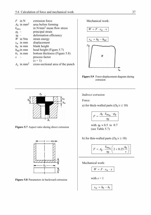
F in N extrusion force A0 in mm2 area before forming kstrm in N/mm2 mean flow stress
p – principal strain F – deformation efficiency
W in Nm strain energy sw in mm displacement h0 in mm blank height hhd in mm head height (Figure 5.7) h1 in mm bottom thickness (Figure 5.8) x – process factor (x = 1) Ap in mm2 cross-sectional area of the punch
Mechanical work:
wW F s x
w 0 hds h h
Figure 5.9 Force-displacement diagram during extrusion
Figure 5.7 Aspect ratio during direct extrusion
Figure 5.8 Parameters in backward extrusion
Indirect extrusion
Force:a) for thick-walled parts (D0 /s 10)
m0 str p
F
A kF
with F 0.5 to 0.7(see Table 5.7)
b) for thin-walled parts (D0 /s 10)
mstr 0p
F2 0.25
k hF As
Mechanical work:
wW F s x
with x = 1
w 0 1s h h
38 5 Extrusion
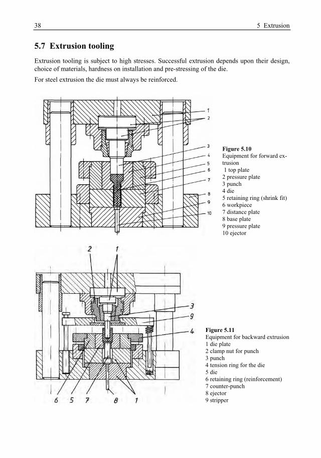
5.7 Extrusion tooling Extrusion tooling is subject to high stresses. Successful extrusion depends upon their design, choice of materials, hardness on installation and pre-stressing of the die. For steel extrusion the die must always be reinforced.
Figure 5.10 Equipment for forward ex-trusion 1 top plate 2 pressure plate 3 punch 4 die 5 retaining ring (shrink fit)6 workpiece 7 distance plate 8 base plate 9 pressure plate 10 ejector
Figure 5.11 Equipment for backward extrusion 1 die plate 2 clamp nut for punch 3 punch 4 tension ring for the die 5 die 6 retaining ring (reinforcement) 7 counter-punch 8 ejector 9 stripper
5.8 Reinforcement calculation for single-reinforced dies 39
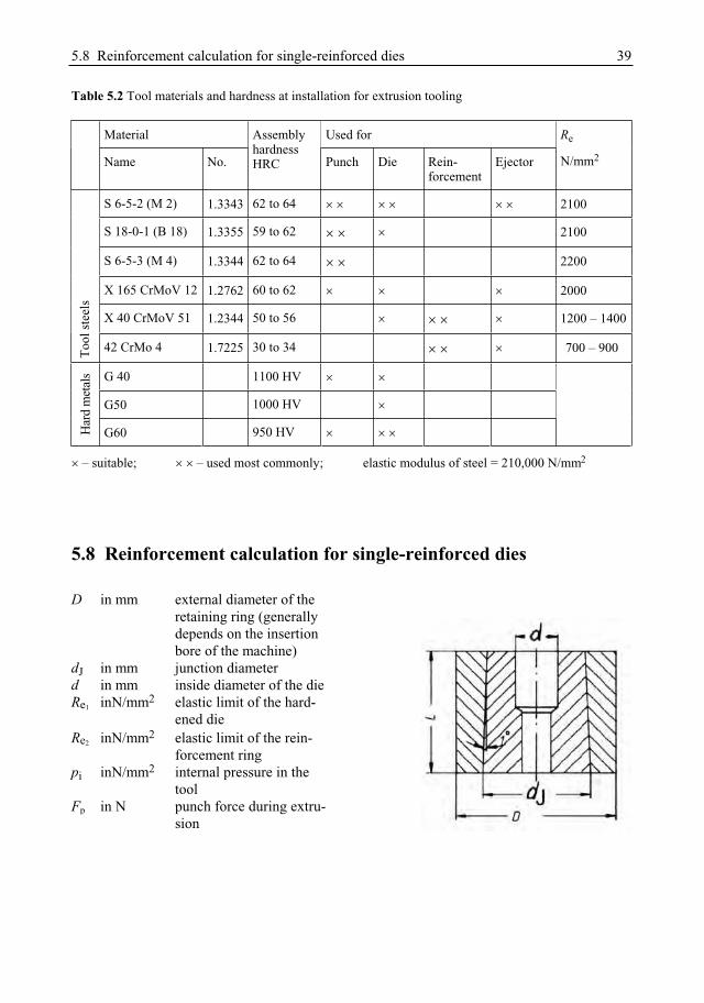
Table 5.2 Tool materials and hardness at installation for extrusion tooling
Material Used for
Name No.
Assembly hardnessHRC Punch Die Rein-
forcement Ejector
Re
N/mm2
S 6-5-2 (M 2) 1.3343 62 to 64 2100
S 18-0-1 (B 18) 1.3355 59 to 62 2100
S 6-5-3 (M 4) 1.3344 62 to 64 2200
X 165 CrMoV 12 1.2762 60 to 62 2000
X 40 CrMoV 51 1.2344 50 to 56 1200 – 1400
Tool
stee
ls
42 CrMo 4 1.7225 30 to 34 700 – 900
G 40 1100 HV
G50 1000 HV
Har
d m
etal
s
G60 950 HV
– suitable; – used most commonly; elastic modulus of steel = 210,000 N/mm2
5.8 Reinforcement calculation for single-reinforced dies
D in mm external diameter of the retaining ring (generallydepends on the insertion bore of the machine)
dJ in mm junction diameter d in mm inside diameter of the dieRe1 inN/mm2 elastic limit of the hard-
ened die Re2 inN/mm2 elastic limit of the rein-
forcement ring pi inN/mm2 internal pressure in the
toolFp in N punch force during extru-
sion

40 5 Extrusion
Table 5.3 Permissible internal pressure depending on reinforcement
piperm (N/mm2) Reinforcement
1000 None
1000 – 1600 Single
1700 – 2000 Double
0p
i strF
p kAp
1
1
ic
e
ppR 2
1
2
e1
e
RK
R3
1 c1
1 112
Q pK
4
2 1 1Q Q K 5
1 2Q Q Q 6
J 0.9d D d 7
J1
ddQ
8
dDQ
9
1F e 21 11
1d Rz Q
E K10
Ap in mm2 cross-sectional area of the punch
z1 in mm absolute interference of the die on the junc-tion diameter dF
in °C temperature in ºC T in °K temperature to join the
retaining ring [T(°K) = (°C) + 273]
in mm/mmK thermal coefficient of expansion for steel = 12.5 · 10–6
mm/mmK c in mm desired clearance,
E in N/mm2 modulus of elasticity (Esteel = 210 kN/mm2)
1
F
z cTd
11
(pi according to [14-2/2 P. 1008]) As d and D are generally known, the junction diameter is most often calculated with equation 7.

5.9 Achievable precision 41
Example:Calculate the junction diameter and the required die clearance for the following data.
Where: pi = 1000 N/mm2 (assumed value) D = 120 mm (die holder bore fitted in the machine) d = 40 mm Re1 = 2100 N/mm2 (for the die material S 6-5-2) Re2 = 1400 N/mm2 (for the reinforcement material X 40 CrMoV 51).
Solution:
dJ 0.9 · 0.9 120 mm 40 mm 62.3 mmD d
dJ = 65 mm is selected
pc =1
2i2e
100 N/ mm2100 N/ mm
pR
= 0.476
K1 = 1
2
2e2e
2100 N/ mm 1.51400 N/ mm
RR
Q1 = c
1
1 1 1 11 1 0.476 0.592 2 1.5
pK
z1 = 12J e 2
1 21
1 65 mm 2100 N/ mm 1 0.5921.5210000 N/ mm
d RQ
E K
z1 = 0.20 mm
If there is total freedom as to the external diameter of the die, then dJ can be determined from equation 8 and D from equation 9; with these values, z1 can then be calculated. In this way, however, considerably larger dimensions for the die usually result.
42 5 Extrusion
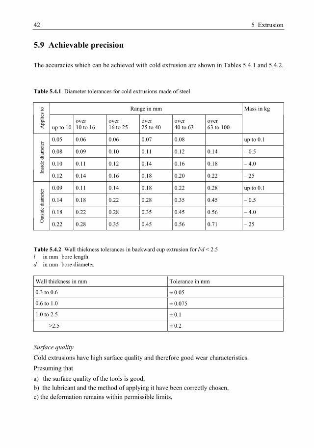
5.9 Achievable precision
The accuracies which can be achieved with cold extrusion are shown in Tables 5.4.1 and 5.4.2.
Table 5.4.1 Diameter tolerances for cold extrusions made of steel
Range in mm
App
lies t
o
up to 10 over10 to 16
over16 to 25
over25 to 40
over40 to 63
over63 to 100
Mass in kg
0.05 0.06 0.06 0.07 0.08 up to 0.1
0.08 0.09 0.10 0.11 0.12 0.14 – 0.5
0.10 0.11 0.12 0.14 0.16 0.18 – 4.0
Insi
de d
iam
eter
0.12 0.14 0.16 0.18 0.20 0.22 – 25
0.09 0.11 0.14 0.18 0.22 0.28 up to 0.1
0.14 0.18 0.22 0.28 0.35 0.45 – 0.5
0.18 0.22 0.28 0.35 0.45 0.56 – 4.0
Out
side d
iam
eter
0.22 0.28 0.35 0.45 0.56 0.71 – 25
Table 5.4.2 Wall thickness tolerances in backward cup extrusion for l/d < 2.5l in mm bore lengthd in mm bore diameter
Wall thickness in mm Tolerance in mm
0.3 to 0.6 ± 0.05
0.6 to 1.0 ± 0.075
1.0 to 2.5 ± 0.1
>2.5 ± 0.2
Surface quality Cold extrusions have high surface quality and therefore good wear characteristics. Presuming that a) the surface quality of the tools is good, b) the lubricant and the method of applying it have been correctly chosen, c) the deformation remains within permissible limits,
5.11 Sequence of operations diagram 43
it is possible to achieve roughness in the region of
Rt = 5 to 10 mon the surfaces where material flow takes place.
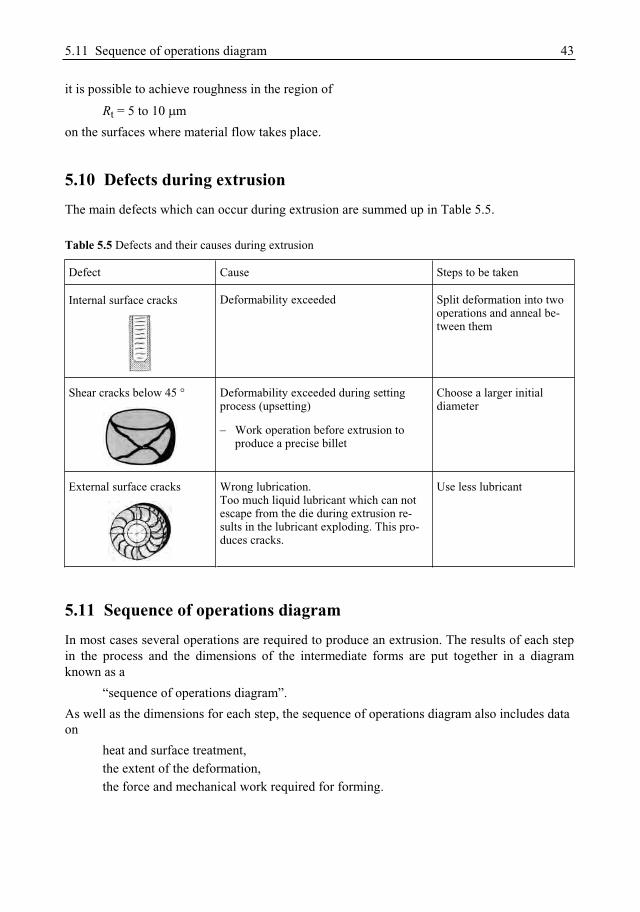
5.10 Defects during extrusion The main defects which can occur during extrusion are summed up in Table 5.5.
Table 5.5 Defects and their causes during extrusion
Defect Cause Steps to be taken
Internal surface cracks Deformability exceeded Split deformation into two operations and anneal be-tween them
Shear cracks below 45 ° Deformability exceeded during setting process (upsetting)
– Work operation before extrusion to produce a precise billet
Choose a larger initial diameter
External surface cracks Wrong lubrication.Too much liquid lubricant which can not escape from the die during extrusion re-sults in the lubricant exploding. This pro-duces cracks.
Use less lubricant
5.11 Sequence of operations diagram In most cases several operations are required to produce an extrusion. The results of each step in the process and the dimensions of the intermediate forms are put together in a diagram known as a
“sequence of operations diagram”. As well as the dimensions for each step, the sequence of operations diagram also includes data on
heat and surface treatment, the extent of the deformation, the force and mechanical work required for forming.

44 5 Extrusion
The sequence of operations diagram is the most important manufacturing document in establish-ing the metal forming machines required, the construction of the tools and the time needed for production.
Figure 5.12 shows a sequence of operations diagram for an M12 x 60 bolt.
Figure 5.12 Steps in the production of a bolt with a pressed hexagonal head
5.12 Example calculations
Example 1 The aim is to produce bolts as in Figure 5.13 out of 42 CrMo 4. The following must be established: operating method, stock, force and mechanical work, where: = 0.7.
Solution:
1. Operating method: forward extrusion 2. Stock Figure 5.13 Collar bolt
2.1. Volume of the finished item 2 2
2 2F 1 2 34 12 4D dV h h D D d d h
= 22 2 2 21 3( )4 3
hD h D D d d d h

5.12 Example calculations 45
2 2 23 mm0.785 (30 mm) 16 mm (900 mm 30 mm 20 mm 400 mm )3
+ (20 mm)2 · 37 mm
VF = 24413 mm3.
Extra for melt and pickling losses: 2 %
VMe =2
100· 24 413 mm3 = 488 mm3.
Volume of the stock VB = VF + VMe = 24 413 mm3 + 488 mm3 = 24 901 mm3.
2.2. Stock dimensions
D0 = 30.0 mm selected, A0 =2(30 mm)
4 = 706.5 mm2
h0 = B
0
VA
=2
2706.5 mm314 mm
= 35.24 mm, h0 = 35.0 mm selected.
3. Force F
3.1. p = ln 0
1
AA
= ln2
2706.5 mm314 mm
= ln 2.25 = 0.81, p = 81 %.
3.2. kstr0= 420 N/mm2, kstrl = 1080 N/mm2, kstrm = 0 1str str
2
k k750 N/mm2.
3.3. F = m0 str p
F
A k=
2 2706.5 mm 750 N/ mm 0.810.7
= 613141 N = 613 kN.
4. Work Wsw = h0 – hk = 35 mm – 16 mm = 19 mm = 0.019 m
W = F · sw · x = 613 kN · 0.019 m · 1 = 11.6 kNm.
Example 2 The aim is to produce casings as in Figure 5.14 out of Al 99.5. where: F = 0.7
Figure 5.14 Casing

46 5 Extrusion
The following must be established: operating method, stock, force and mechanical work.
Solution 1: 1. Operating method: backward extrusion 2. Stock
2.1. Volume of the finished item
VF = 2 22b 1i i( )4 4
d s D d h
= (28 mm)24
1.5 mm + (302 – 282) mm24
60 mm = 6386.7 mm3
Extra to make up for melt and pickling losses: 1 %
VMe =1
100 6336 mm3 64 mm3.
Volume of the stock VB = VF + KMe = 6386.7 mm3 + 64 mm3 = 6451 mm3.
2.2. Stock dimensions
D0 = 30– 0.1 mm, A0 = 706.5 mm2
h0 =3F20
6451 mm 9.13 mm,706.5 mm
VA
h0 = 9.0 mm selected.
3. Force F
3.1. p = 0
0
30 mmln 0.16 ln30 mm 28 mm
DD d
– 0.16 = ln 15 – 0.16
= 2.70 – 0.16 = 2.54
p = 254 %.
3.2. Flow stress from the flow stress curve or Table 1 (Part III)
kstr0 = 60 N/mm2, kstr1 = 184 N/mm2,
kstrm = 0 12 2str str 60 N/ mm 184 N/mm
2 2k k
= 122 N/mm2
3.3. F = m2 2str 0
pF
(28 mm) 122 N/mm 92 0.25 2 0.254 0.7 1
k hAc
= 455836 N = 456 kN.
4.1. Deformation displacement
sw = h0 – h1 = 9 mm – 1.5 mm = 7.5 mm = 0.0075 m
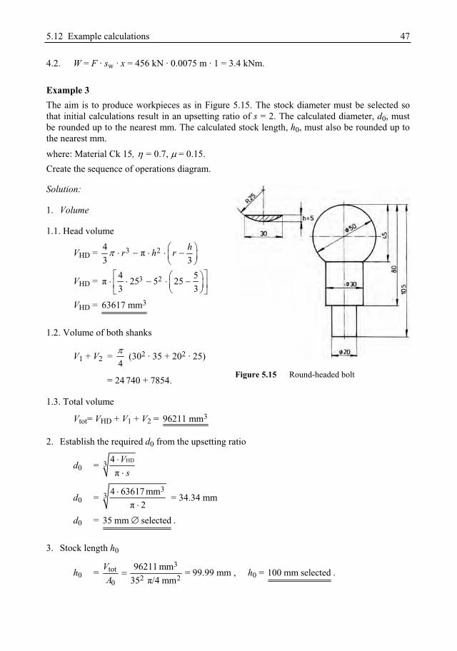
5.12 Example calculations 47
4.2. W = F · sw · x = 456 kN · 0.0075 m · 1 = 3.4 kNm.
Example 3 The aim is to produce workpieces as in Figure 5.15. The stock diameter must be selected so that initial calculations result in an upsetting ratio of s = 2. The calculated diameter, d0, must be rounded up to the nearest mm. The calculated stock length, h0, must also be rounded up to the nearest mm. where: Material Ck 15, = 0.7, = 0.15.Create the sequence of operations diagram.
Solution:
1. Volume
1.1. Head volume
VHD = 3 243 3
hr h r
VHD = 3 24 525 5 253 3
VHD = 363617 mm
1.2. Volume of both shanks
V1 + V2 =4
(302 · 35 + 202 · 25)
= 24 740 + 7854. Figure 5.15 Round-headed bolt
1.3. Total volume
Vtot= VHD + V1 + V2 = 396211 mm
2. Establish the required d0 from the upsetting ratio
d0 = HD3 4 Vs
d0 = 3
3 4 63617 mm2
= 34.34 mm
d0 = 35 mm selected .
3. Stock length h0
h0 = 3tot
2 20
96211 mm35 /4 mm
VA
= 99.99 mm , h0 = 100 mm selected .
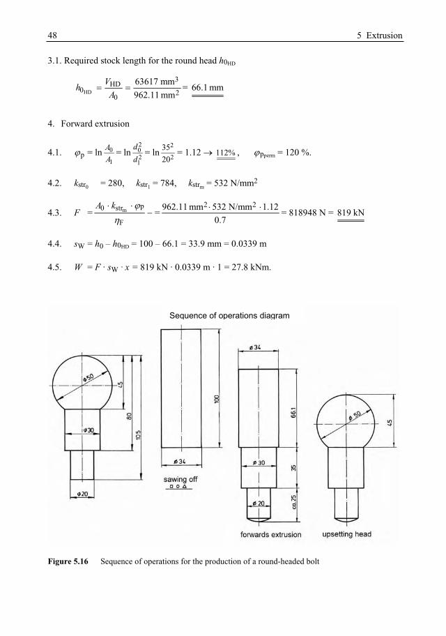
48 5 Extrusion
3.1. Required stock length for the round head h0HD
HD
3HD0 20
63617 mm962.11 mm
VhA
= 66.1 mm
4. Forward extrusion
4.1. p = ln 0
1
AA
= ln2021
dd
= ln2
23520
= 1.12 112% , pperm = 120 %.
4.2. kstr0 = 280, kstr1 = 784, kstrm = 532 N/mm2
4.3. F = m p0 str
F
A k=
2 2962.11 mm 532 N/mm 1.120.7
= 818948 N = 819 kN
4.4. sW = h0 – h0HD = 100 – 66.1 = 33.9 mm = 0.0339 m
4.5. W = F · sW · x = 819 kN · 0.0339 m · 1 = 27.8 kNm.
Figure 5.16 Sequence of operations for the production of a round-headed bolt
Sequence of operations diagram

5.13 Shape classification 49
5. Upsetting (heading)
5.1 p = ln HD0
HD
66.1ln 0.384 38.4%45
hh
p = 150 %.
5.2 kstr0= 280, kstr1 = 670, kstrm = 475 N/mm2
5.3 F = A1 · kstr11
1
113
dh
= 2
2 250 1 50 mmmm 670 N/mm 1 0.154 3 45 mm
F = 1 387 896.7 N = 1388 kN
5.4 W = m3 2HD str p
F
63617 mm 475 N / mm 0.3840.7
V k
W = 16 576 771 Nmm = 16.6 kN m
5.13 Shape classification For operations scheduling, during which the sequence of operations plans for the extrusions are produced, it is important to collect and record empirical values. This is why a shape classification table is used in which the various extrusion shapes are or-dered according to operating method, sequence of operations, degree of difficulty etc. Table 5.6 shows a shape classification table. The advantages of this kind of classification are: – Production of sequence of operations plans for new parts.
If sequence of operations plans already exist in the shape classification table for similar parts, this makes the production of a new sequence of operations plan easier as it can be ba-sed on similar shapes. This means the induction of new inexperienced workers is made far simpler and the need for specialists is reduced.
– Furthermore, groups of the same shape have the same or a similar amount of difficulty during pressing. Depending on the group of shapes, the extent of the deformation efficiency to be expected can also be deduced (see Table 5.7).
– There are also advantages for tool manufacture. Similar shapes also produce similar ele-ments as concerns tools; these elements can be standardised within a company, simplified and thus produced at less expense.
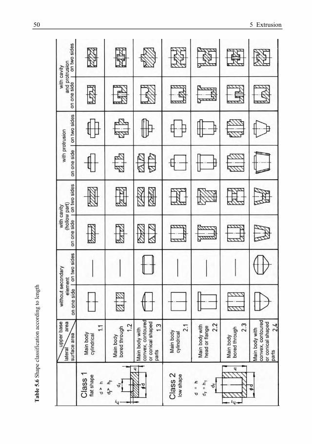
50 5 Extrusion
Tab
le 5
.6 S
hape
cla
ssifi
catio
n ac
cord
ing
to le
ngth
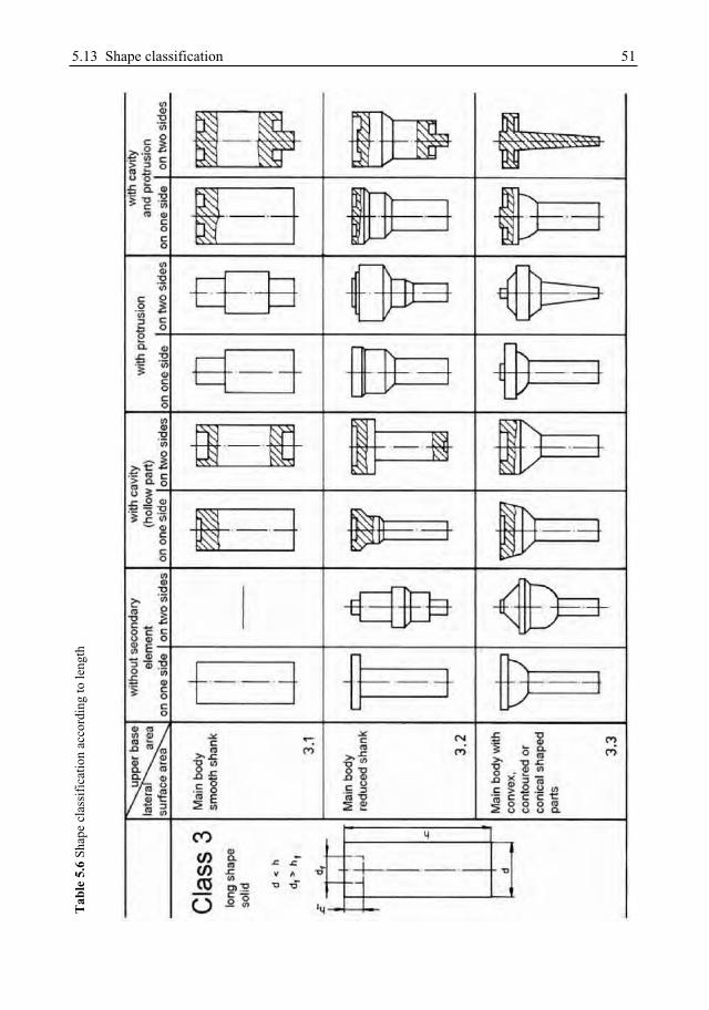
5.13 Shape classification 51 T
able
5.6
Sha
pe c
lass
ifica
tion
acco
rdin
g to
leng
th
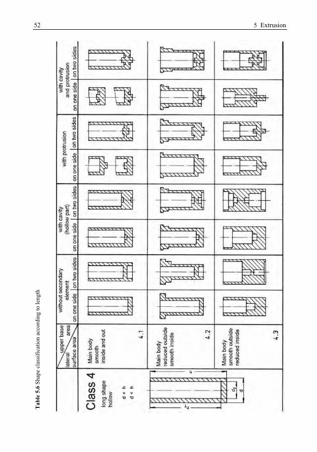
52 5 Extrusion
Tab
le 5
.6 S
hape
cla
ssifi
catio
n ac
cord
ing
to le
ngth
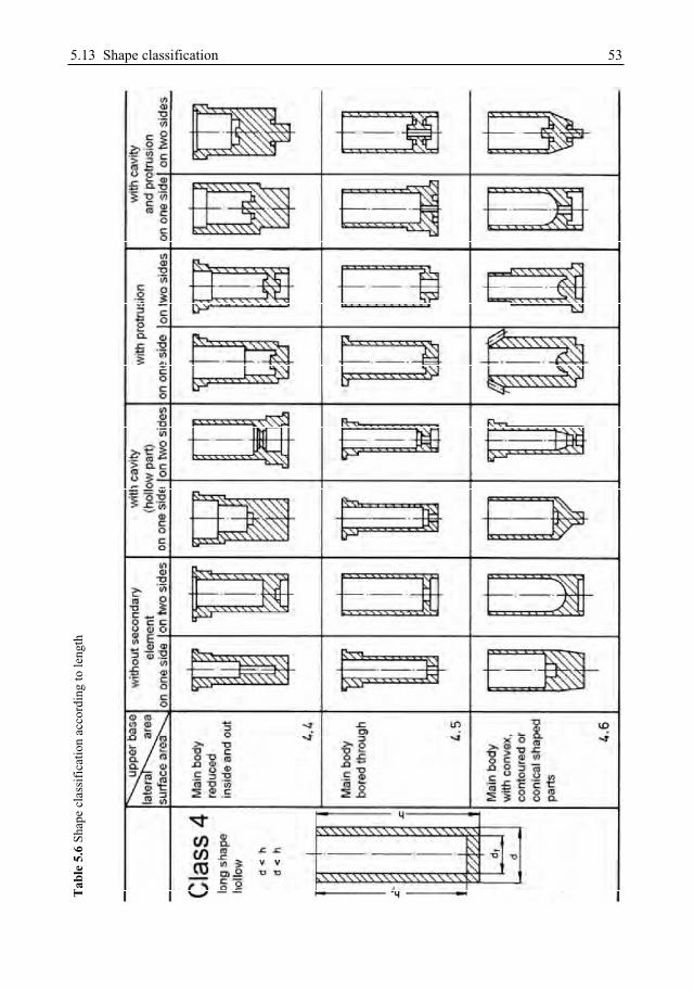
5.13 Shape classification 53 T
able
5.6
Sha
pe c
lass
ifica
tion
acco
rdin
g to
leng
th
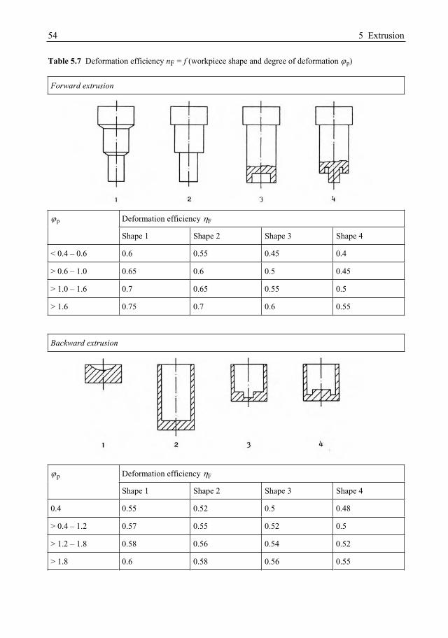
54 5 Extrusion
Table 5.7 Deformation efficiency nF = f (workpiece shape and degree of deformation p)
Forward extrusion
Deformation efficiency Fp
Shape 1 Shape 2 Shape 3 Shape 4
< 0.4 – 0.6 0.6 0.55 0.45 0.4
> 0.6 – 1.0 0.65 0.6 0.5 0.45
> 1.0 – 1.6 0.7 0.65 0.55 0.5
> 1.6 0.75 0.7 0.6 0.55
Backward extrusion
Deformation efficiency Fp
Shape 1 Shape 2 Shape 3 Shape 4
0.4 0.55 0.52 0.5 0.48
> 0.4 – 1.2 0.57 0.55 0.52 0.5
> 1.2 – 1.8 0.58 0.56 0.54 0.52
> 1.8 0.6 0.58 0.56 0.55

5.14 Exercise on Chapter 5 55
5.14 Exercise on Chapter 5
1. What extrusion methods do you know? 2. Which values are principal strain calculated from during extrusion? 3. How is the deformation displacement established? 4. Name the most important elements of extrusion tooling. 5. Why must the die be reinforced? 6. What values does the deformation efficiency depend upon? 7. What has gone wrong if internal surface cracks appear during backward extrusion? 8. What is a sequence of operations diagram and what is it used for? 9. What kind of workpieces are produced using backward extrusion and what with forward
extrusion? 10. What method must be used to produce a round-headed bolt? 11. What manufacturing process is used to produce a toothpaste tube? Sketch the sequence of
operations diagram. 12. Why is a pillar guide needed in extrusion tooling?
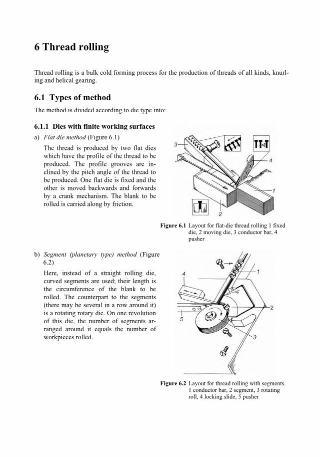
6 Thread rolling
Thread rolling is a bulk cold forming process for the production of threads of all kinds, knurl-ing and helical gearing.
6.1 Types of method The method is divided according to die type into:
6.1.1 Dies with finite working surfaces a) Flat die method (Figure 6.1)
The thread is produced by two flat dies which have the profile of the thread to be produced. The profile grooves are in-clined by the pitch angle of the thread to be produced. One flat die is fixed and the other is moved backwards and forwards by a crank mechanism. The blank to be rolled is carried along by friction.
Figure 6.1 Layout for flat-die thread rolling 1 fixed die, 2 moving die, 3 conductor bar, 4 pusher
b) Segment (planetary type) method (Figure 6.2)Here, instead of a straight rolling die, curved segments are used; their length is the circumference of the blank to be rolled. The counterpart to the segments (there may be several in a row around it) is a rotating rotary die. On one revolution of this die, the number of segments ar-ranged around it equals the number of workpieces rolled.
Figure 6.2 Layout for thread rolling with segments. 1 conductor bar, 2 segment, 3 rotating roll, 4 locking slide, 5 pusher
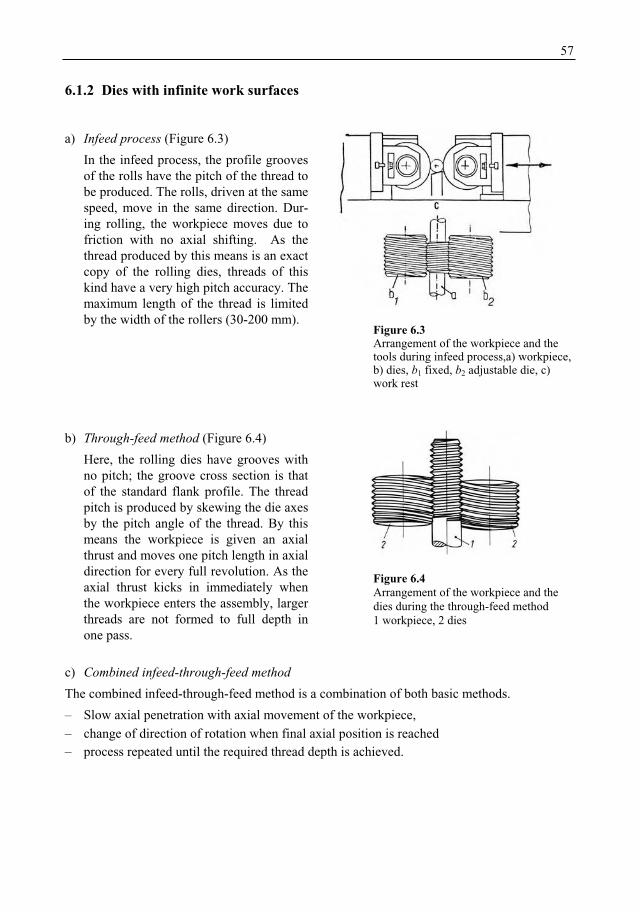
57
6.1.2 Dies with infinite work surfaces
a) Infeed process (Figure 6.3) In the infeed process, the profile grooves of the rolls have the pitch of the thread to be produced. The rolls, driven at the same speed, move in the same direction. Dur-ing rolling, the workpiece moves due to friction with no axial shifting. As the thread produced by this means is an exact copy of the rolling dies, threads of this kind have a very high pitch accuracy. The maximum length of the thread is limited by the width of the rollers (30-200 mm).
Figure 6.3 Arrangement of the workpiece and the
tools during infeed process,a) workpiece,b) dies, b1 fixed, b2 adjustable die, c) work rest
b) Through-feed method (Figure 6.4) Here, the rolling dies have grooves with no pitch; the groove cross section is that of the standard flank profile. The thread pitch is produced by skewing the die axes by the pitch angle of the thread. By this means the workpiece is given an axial thrust and moves one pitch length in axial direction for every full revolution. As the axial thrust kicks in immediately when the workpiece enters the assembly, larger threads are not formed to full depth in one pass.
Figure 6.4 Arrangement of the workpiece and the
dies during the through-feed method1 workpiece, 2 dies
c) Combined infeed-through-feed methodThe combined infeed-through-feed method is a combination of both basic methods. – Slow axial penetration with axial movement of the workpiece, – change of direction of rotation when final axial position is reached – process repeated until the required thread depth is achieved.
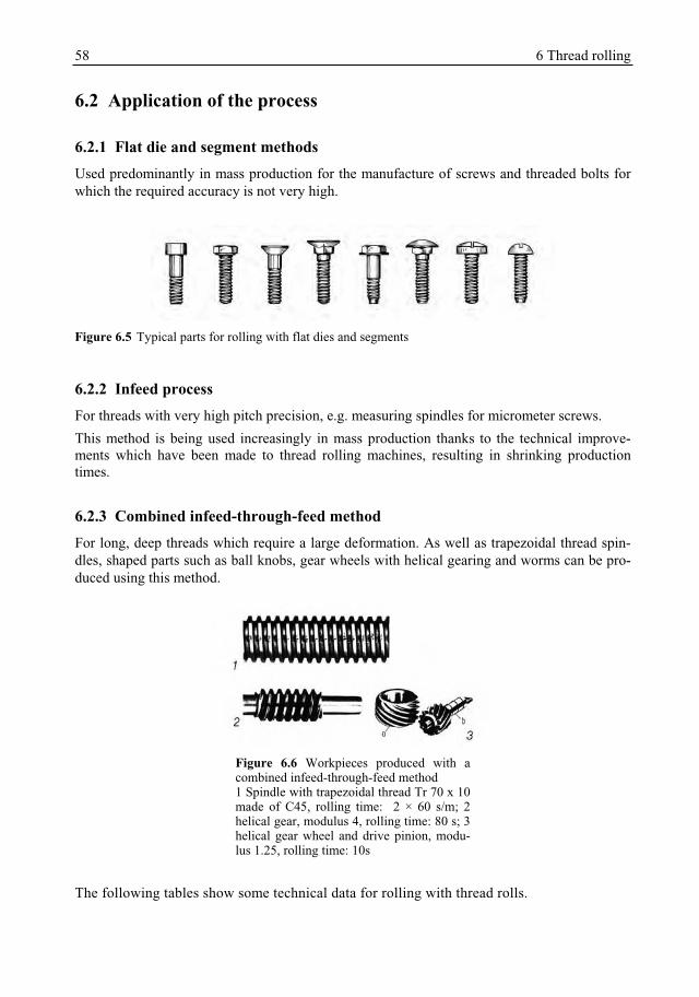
58 6 Thread rolling
6.2 Application of the process
6.2.1 Flat die and segment methods Used predominantly in mass production for the manufacture of screws and threaded bolts for which the required accuracy is not very high.
Figure 6.5 Typical parts for rolling with flat dies and segments
6.2.2 Infeed process For threads with very high pitch precision, e.g. measuring spindles for micrometer screws. This method is being used increasingly in mass production thanks to the technical improve-ments which have been made to thread rolling machines, resulting in shrinking production times.
6.2.3 Combined infeed-through-feed method For long, deep threads which require a large deformation. As well as trapezoidal thread spin-dles, shaped parts such as ball knobs, gear wheels with helical gearing and worms can be pro-duced using this method.
Figure 6.6 Workpieces produced with a combined infeed-through-feed method 1 Spindle with trapezoidal thread Tr 70 x 10 made of C45, rolling time: 2 × 60 s/m; 2 helical gear, modulus 4, rolling time: 80 s; 3 helical gear wheel and drive pinion, modu-lus 1.25, rolling time: 10s
The following tables show some technical data for rolling with thread rolls.
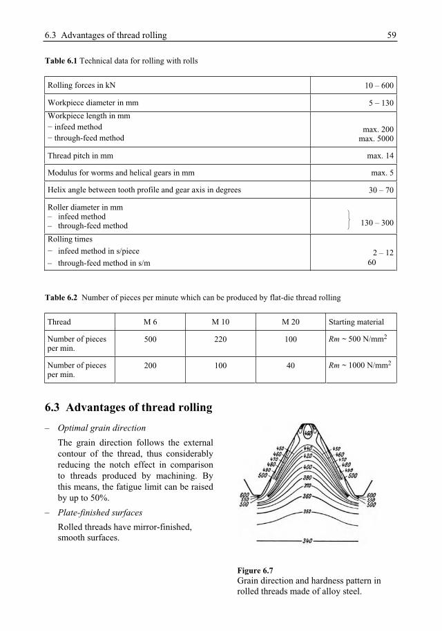
6.3 Advantages of thread rolling 59
Table 6.1 Technical data for rolling with rolls
Rolling forces in kN 10 – 600
Workpiece diameter in mm 5 – 130 Workpiece length in mm
infeed method through-feed method
max. 200 max. 5000
Thread pitch in mm max. 14
Modulus for worms and helical gears in mm max. 5
Helix angle between tooth profile and gear axis in degrees 30 – 70
Roller diameter in mm – infeed method – through-feed method 130 – 300
Rolling times infeed method in s/piece
– through-feed method in s/m 2 – 12
60
Table 6.2 Number of pieces per minute which can be produced by flat-die thread rolling
Thread M 6 M 10 M 20 Starting material
Number of pieces per min.
500 220 100 Rm ~ 500 N/mm2
Number of pieces per min.
200 100 40 Rm ~ 1000 N/mm2
6.3 Advantages of thread rolling – Optimal grain direction
The grain direction follows the external contour of the thread, thus considerably reducing the notch effect in comparison to threads produced by machining. By this means, the fatigue limit can be raised by up to 50%.
– Plate-finished surfacesRolled threads have mirror-finished, smooth surfaces.
Figure 6.7Grain direction and hardness pattern in rolled threads made of alloy steel.

60 6 Thread rolling
– Work hardeningThanks to work hardening, there is a considerable increase in strength (Figure 6.7) which, in combination with the plate-finished surface, means mechanical wear is lessened.
– Material savingsThe material savings with rolled threads, compared to machined threads, is about 20%.
– Short production timesRolling times are very short compared to the production of threads by machining (see Ta-bles 6.1 and 6.2).
– Nearly all the main materials used in practice can be rolledNearly all steels can be rolled, except for free-cutting steels, up to a failure strain of over 8% and a maximum strength of 1200 N/mm2. Soft Ms 58-63 can also be rolled.
6.4 Establishing the initial diameter The initial diameter of the bolt can be established mathematically with the following equations depending on the kind of thread.
For metric threads
0 0.67d d h
For Whitworth threads
0 0.64d d h
For coated threadse.g. galvanized, chromium-plated
ct 02
sin2
zd d
h in mm thread pitch d0 in mm initial diameter of bolt d in mm external diameter of thread dp in mm pitch diameter
in degrees thread angle z in mm thickness of the metal coating dct in mm initial bolt diameter for parts which are metal coated.
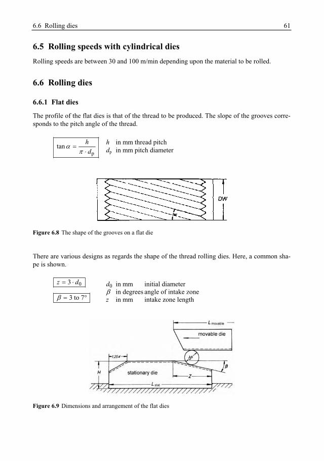
6.6 Rolling dies 61
6.5 Rolling speeds with cylindrical dies Rolling speeds are between 30 and 100 m/min depending upon the material to be rolled.
6.6 Rolling dies
6.6.1 Flat dies
The profile of the flat dies is that of the thread to be produced. The slope of the grooves corre-sponds to the pitch angle of the thread.
ptan h
dh in mm thread pitch dp in mm pitch diameter
Figure 6.8 The shape of the grooves on a flat die
There are various designs as regards the shape of the thread rolling dies. Here, a common sha-pe is shown.
03z d
3 to 7
d0 in mm initial diameter in degrees angle of intake zone
z in mm intake zone length
Figure 6.9 Dimensions and arrangement of the flat dies

62 6 Thread rolling
The thread profile is also fully deep in the intake area. The length of the die should be at least 15 d0.The movable die should be 15 to 20 mm longer than the stationary die. The die width DW
1 3DW L h
DW in mm die width h in mm thread pitch L1 in mm length of the thread on the workpiece H in mm die thickness L in mm die length
Table 6.3 Die dimensions for metric threads
Die length in mm Nominal thread diameter movable
Lm
fixedLf
Die width DWin mm
Die thickness Hin mm
Intake length zin mm
M 6 125 110 40 25 20
M 10 170 150 45 30 28
M 16 250 230 65 45 46
Table 6.4 Tool materials for flat dies and rollers
Material no. 1.2379 1.2601 1.3343
HRC assembly hardness 59 to 61 59 to 61 60 to 61
6.6.2 Dimensions of the rolling dies
– Infeed method (screw threads)
p p p p; / /FLD d D d FL fl kfl
p pD k d
ex pD k d t

6.7 Example 63
Dp in mm pitch diameter of the rollers dr in mm pitch diameter of the thread to be rolled Dexin mm external diameter of the roll t in mm thread depth FL by number number of flights on the die fl by number number of flights on the thread k factor which depends upon the ratio of FL/fl
– Through-feed method with rolling grooves without a pitchIn the through-feed production method, the diameter of the roller does not depend upon the diameter of the thread to be produced. For this reason it is generally selected according to the dimensions of the machine.
– Combined infeed-through-feed method
Wpp
W
sinsin( )
D k d
w = pitch angle of the workpiece thread = swivel angle of the die axes
Table 6.5 shows common rotary die materials and the corresponding assembly hardnesses. Rotary die life depends upon the strength of the material to be rolled.
Table 6.5 Tool lives of rotary dies
Material strength Rmin N/mm2 Number of units per tool
1000 800600
100000 200000 300000
6.7 Example
The aim is to produce threads of M10 x 50 long. Calculate the initial diameter required.
Solution:
d0 = d – 0.67 · h = 10 mm – 0.67 · 1.5 mm = 9.0 mm
h = 1.5 mm from the table.

64 6 Thread rolling
Figure 6.10Automatic high-performance thread rolling ma-chine, type R 2 L (Photograph from Hilgeland works, Wuppertal, Germany)
6.8 Thread rolling machines Here, a difference is made between: Flat die thread rolling machines Thread rolling machines with cylindrical diesThread rolling machines with cylindrical and segment dies.
6.8.1 Flat die thread rolling machinesThe basic concept behind the construction of these machines is practically the same for all manufacturers. The standard is built as a box-shaped cast construction or, as in the machine shown in Figure 6.10, a combina-tion of welded and cast construction. A slide takes up the movable die. The slide guide is mostly designed as an adjustable prism or V-block. The rolling slide (Figure 6.11) is driven by the crank wheel (3) located on the crankshaft, via the connecting rod (2). The smooth running of the machine is achieved by means of the pulley, which is designed as a flywheel. The workpieces are sorted using a trommel (Figure 6.10) or an oscillating conveyor and guided into the working area by hardened conductor tracks. A pusher (Figure 6.1) controlled by cams brings the blank be-tween the rollers. The number of pieces per time unit which can be produced using these machines is shown in Table 6.2. Flat die thread rolling machines are used mainly in the screw and standard part in-dustry.
Figure 6.11The drive of a flat die thread rolling machine of the Hilgeland company. 1 slide, 2 connecting rod, 3 crank wheel, 4 crankshaft, 5 standard, 6 moving flat die, 7 fixed flat die
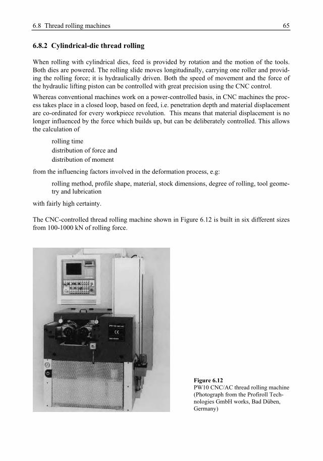
6.8 Thread rolling machines 65
6.8.2 Cylindrical-die thread rolling
When rolling with cylindrical dies, feed is provided by rotation and the motion of the tools. Both dies are powered. The rolling slide moves longitudinally, carrying one roller and provid-ing the rolling force; it is hydraulically driven. Both the speed of movement and the force of the hydraulic lifting piston can be controlled with great precision using the CNC control. Whereas conventional machines work on a power-controlled basis, in CNC machines the proc-ess takes place in a closed loop, based on feed, i.e. penetration depth and material displacement are co-ordinated for every workpiece revolution. This means that material displacement is no longer influenced by the force which builds up, but can be deliberately controlled. This allows the calculation of
rolling time distribution of force and distribution of moment
from the influencing factors involved in the deformation process, e.g:
rolling method, profile shape, material, stock dimensions, degree of rolling, tool geome-try and lubrication
with fairly high certainty.
The CNC-controlled thread rolling machine shown in Figure 6.12 is built in six different sizes from 100-1000 kN of rolling force.
Figure 6.12 PW10 CNC/AC thread rolling machine (Photograph from the Profiroll Tech-nologies GmbH works, Bad Düben, Germany)
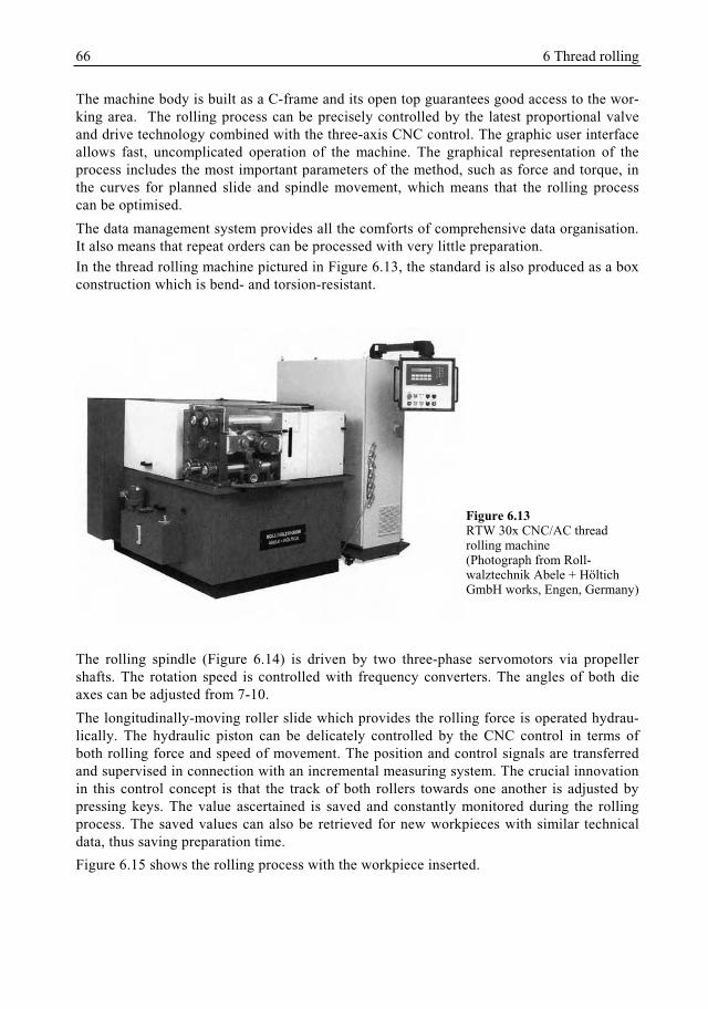
66 6 Thread rolling
The machine body is built as a C-frame and its open top guarantees good access to the wor-king area. The rolling process can be precisely controlled by the latest proportional valve and drive technology combined with the three-axis CNC control. The graphic user interface allows fast, uncomplicated operation of the machine. The graphical representation of the process includes the most important parameters of the method, such as force and torque, in the curves for planned slide and spindle movement, which means that the rolling process can be optimised. The data management system provides all the comforts of comprehensive data organisation. It also means that repeat orders can be processed with very little preparation. In the thread rolling machine pictured in Figure 6.13, the standard is also produced as a box construction which is bend- and torsion-resistant.
Figure 6.13 RTW 30x CNC/AC thread rolling machine (Photograph from Roll-walztechnik Abele + Höltich GmbH works, Engen, Germany)
The rolling spindle (Figure 6.14) is driven by two three-phase servomotors via propeller shafts. The rotation speed is controlled with frequency converters. The angles of both die axes can be adjusted from 7-10. The longitudinally-moving roller slide which provides the rolling force is operated hydrau-lically. The hydraulic piston can be delicately controlled by the CNC control in terms of both rolling force and speed of movement. The position and control signals are transferred and supervised in connection with an incremental measuring system. The crucial innovation in this control concept is that the track of both rollers towards one another is adjusted by pressing keys. The value ascertained is saved and constantly monitored during the rolling process. The saved values can also be retrieved for new workpieces with similar technical data, thus saving preparation time. Figure 6.15 shows the rolling process with the workpiece inserted.
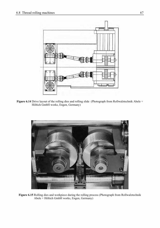
6.8 Thread rolling machines 67
Figure 6.14 Drive layout of the rolling dies and rolling slide (Photograph from Rollwalztechnik Abele + Höltich GmbH works, Engen, Germany)
Figure 6.15 Rolling dies and workpiece during the rolling process (Photograph from Rollwalztechnik Abele + Höltich GmbH works, Engen, Germany)
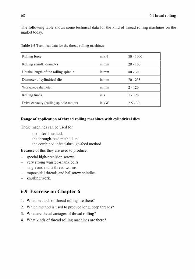
68 6 Thread rolling
The following table shows some technical data for the kind of thread rolling machines on the market today.
Table 6.6 Technical data for the thread rolling machines
Rolling force in kN 80 - 1000
Rolling spindle diameter in mm 28 - 100
Uptake length of the rolling spindle in mm 80 - 300
Diameter of cylindrical die in mm 70 - 235
Workpiece diameter in mm 2 - 120
Rolling times in s 1 - 120
Drive capacity (rolling spindle motor) in kW 2.5 - 30
Range of application of thread rolling machines with cylindrical dies
These machines can be used for the infeed method, the through-feed method and the combined infeed-through-feed method.
Because of this they are used to produce: – special high-precision screws – very strong waisted-shank bolts – single and multi-thread worms – trapezoidal threads and ballscrew spindles – knurling work.
6.9 Exercise on Chapter 6 1. What methods of thread rolling are there? 2. Which method is used to produce long, deep threads? 3. What are the advantages of thread rolling? 4. What kinds of thread rolling machines are there?
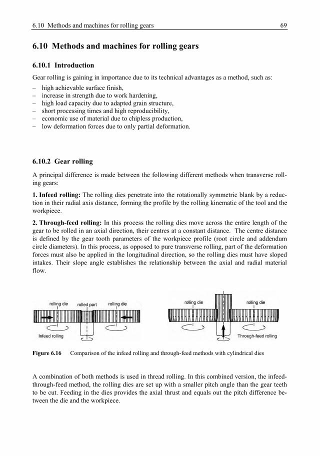
6.10 Methods and machines for rolling gears 69
6.10 Methods and machines for rolling gears
6.10.1 Introduction Gear rolling is gaining in importance due to its technical advantages as a method, such as: – high achievable surface finish, – increase in strength due to work hardening, – high load capacity due to adapted grain structure, – short processing times and high reproducibility, – economic use of material due to chipless production, – low deformation forces due to only partial deformation.
6.10.2 Gear rolling
A principal difference is made between the following different methods when transverse roll-ing gears:
1. Infeed rolling: The rolling dies penetrate into the rotationally symmetric blank by a reduc-tion in their radial axis distance, forming the profile by the rolling kinematic of the tool and the workpiece.
2. Through-feed rolling: In this process the rolling dies move across the entire length of the gear to be rolled in an axial direction, their centres at a constant distance. The centre distance is defined by the gear tooth parameters of the workpiece profile (root circle and addendum circle diameters). In this process, as opposed to pure transverse rolling, part of the deformation forces must also be applied in the longitudinal direction, so the rolling dies must have sloped intakes. Their slope angle establishes the relationship between the axial and radial material flow.
Figure 6.16 Comparison of the infeed rolling and through-feed methods with cylindrical dies
A combination of both methods is used in thread rolling. In this combined version, the infeed-through-feed method, the rolling dies are set up with a smaller pitch angle than the gear teeth to be cut. Feeding in the dies provides the axial thrust and equals out the pitch difference be-tween the die and the workpiece.
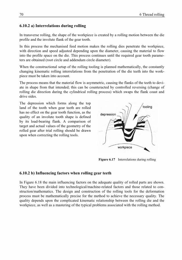
70 6 Thread rolling
6.10.2 a) Interrelations during rolling
In transverse rolling, the shape of the workpiece is created by a rolling motion between the die profile and the involute flank of the gear tooth.
In this process the mechanised feed motion makes the rolling dies penetrate the workpiece, with direction and speed adjusted depending upon the diameter, causing the material to flow into the profile space on the die. This process continues until the required gear tooth parame-ters are obtained (root circle and addendum circle diameter).
When the constructional setup of the rolling tooling is planned mathematically, the constantly changing kinematic rolling interrelations from the penetration of the die teeth into the work-piece must be taken into account.
The process means that the material flow is asymmetric, causing the flanks of the teeth to devi-ate in shape from that intended; this can be counteracted by controlled reversing (change of rolling die direction during the cylindrical rolling process) which swaps the flank coast and drive sides.
The depression which forms along the top land of the tooth when gear teeth are rolled has no effect on the gear tooth function, as the quality of an involute tooth shape is defined by its load-bearing flank. A comparison oftarget and actual values of the geometry of the rolled gear after trial rolling should be drawn upon when correcting the rolling tools.
Figure 6.17 Interrelations during rolling
6.10.2 b) Influencing factors when rolling gear teeth
In Figure 6.18 the main influencing factors on the adequate quality of rolled parts are shown. They have been divided into technological/machine-related factors and those related to con-struction/mathematics. The design and construction of the rolling tools for the deformation process must be mathematically precise for the method to achieve the necessary quality. The quality depends upon the complicated kinematic relationship between the rolling die and the workpiece, as well as a mastering of the typical problems associated with the rolling method.
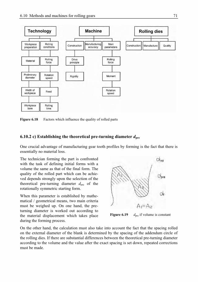
6.10 Methods and machines for rolling gears 71
Figure 6.18 Factors which influence the quality of rolled parts
6.10.2 c) Establishing the theoretical pre-turning diameter dpre
One crucial advantage of manufacturing gear tooth profiles by forming is the fact that there is essentially no material loss.
The technician forming the part is confronted with the task of defining initial forms with a volume the same as that of the final form. The quality of the rolled part which can be achie-ved depends strongly upon the selection of the theoretical pre-turning diameter dpre of the rotationally symmetric starting form.
When this parameter is established by mathe-matical / geometrical means, two main criteria must be weighed up. On one hand, the pre-turning diameter is worked out according to the material displacement which takes place during the forming process.
Figure 6.19 dpre if volume is constant
On the other hand, the calculation must also take into account the fact that the spacing rolled on the external diameter of the blank is determined by the spacing of the addendum circle of the rolling dies. If there are substantial differences between the theoretical pre-turning diameter according to the volume and the value after the exact spacing is set down, repeated corrections must be made.
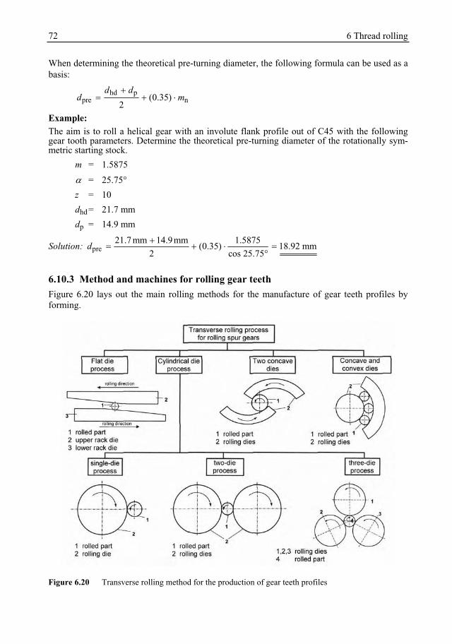
72 6 Thread rolling
When determining the theoretical pre-turning diameter, the following formula can be used as a basis:
hd ppre n(0.35)
2d d
d m
Example: The aim is to roll a helical gear with an involute flank profile out of C45 with the following gear tooth parameters. Determine the theoretical pre-turning diameter of the rotationally sym-metric starting stock.
m = 1.5875 = 25.75°
z = 10 dhd = 21.7 mm dp = 14.9 mm
Solution: pre21.7 mm 14.9mm 1.5875(0.35) 18.92 mm
2 cos 25.75d
6.10.3 Method and machines for rolling gear teeth Figure 6.20 lays out the main rolling methods for the manufacture of gear teeth profiles by forming.
Figure 6.20 Transverse rolling method for the production of gear teeth profiles
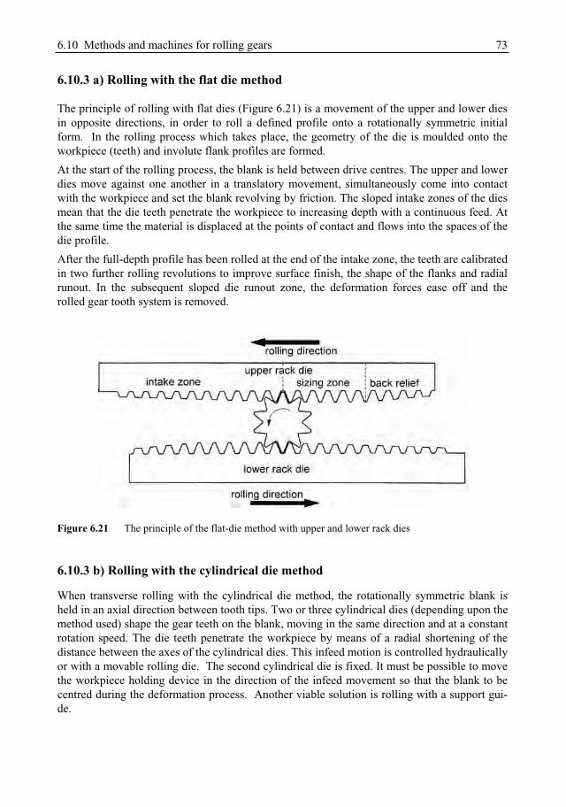
6.10 Methods and machines for rolling gears 73
6.10.3 a) Rolling with the flat die method
The principle of rolling with flat dies (Figure 6.21) is a movement of the upper and lower dies in opposite directions, in order to roll a defined profile onto a rotationally symmetric initial form. In the rolling process which takes place, the geometry of the die is moulded onto the workpiece (teeth) and involute flank profiles are formed. At the start of the rolling process, the blank is held between drive centres. The upper and lower dies move against one another in a translatory movement, simultaneously come into contact with the workpiece and set the blank revolving by friction. The sloped intake zones of the dies mean that the die teeth penetrate the workpiece to increasing depth with a continuous feed. At the same time the material is displaced at the points of contact and flows into the spaces of the die profile. After the full-depth profile has been rolled at the end of the intake zone, the teeth are calibrated in two further rolling revolutions to improve surface finish, the shape of the flanks and radial runout. In the subsequent sloped die runout zone, the deformation forces ease off and the rolled gear tooth system is removed.
Figure 6.21 The principle of the flat-die method with upper and lower rack dies
6.10.3 b) Rolling with the cylindrical die method
When transverse rolling with the cylindrical die method, the rotationally symmetric blank is held in an axial direction between tooth tips. Two or three cylindrical dies (depending upon the method used) shape the gear teeth on the blank, moving in the same direction and at a constant rotation speed. The die teeth penetrate the workpiece by means of a radial shortening of the distance between the axes of the cylindrical dies. This infeed motion is controlled hydraulically or with a movable rolling die. The second cylindrical die is fixed. It must be possible to move the workpiece holding device in the direction of the infeed movement so that the blank to be centred during the deformation process. Another viable solution is rolling with a support gui-de.
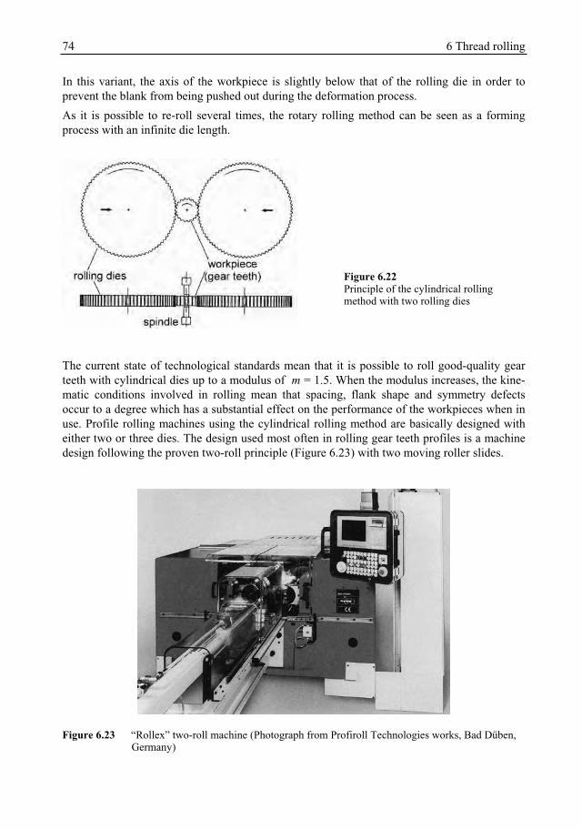
74 6 Thread rolling
In this variant, the axis of the workpiece is slightly below that of the rolling die in order to prevent the blank from being pushed out during the deformation process. As it is possible to re-roll several times, the rotary rolling method can be seen as a forming process with an infinite die length.
Figure 6.22 Principle of the cylindrical rolling method with two rolling dies
The current state of technological standards mean that it is possible to roll good-quality gear teeth with cylindrical dies up to a modulus of m = 1.5. When the modulus increases, the kine-matic conditions involved in rolling mean that spacing, flank shape and symmetry defects occur to a degree which has a substantial effect on the performance of the workpieces when in use. Profile rolling machines using the cylindrical rolling method are basically designed with either two or three dies. The design used most often in rolling gear teeth profiles is a machine design following the proven two-roll principle (Figure 6.23) with two moving roller slides.
Figure 6.23 “Rollex” two-roll machine (Photograph from Profiroll Technologies works, Bad Düben, Germany)
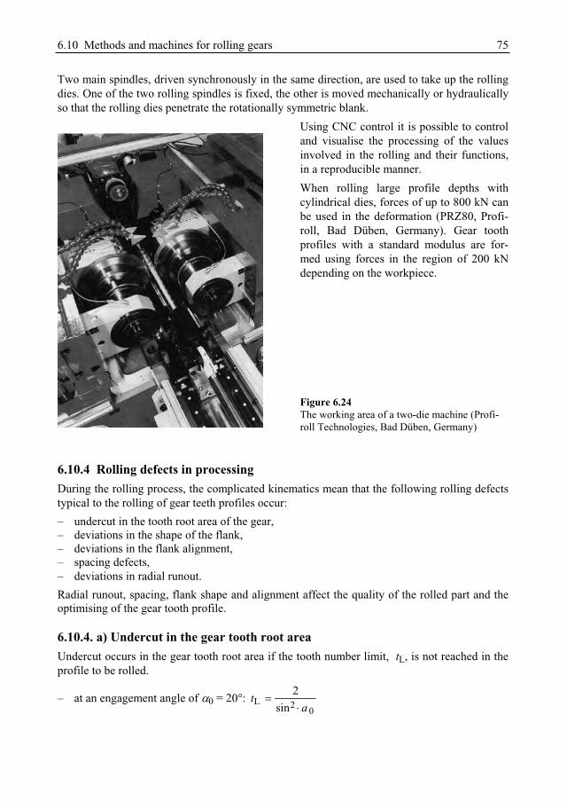
6.10 Methods and machines for rolling gears 75
Two main spindles, driven synchronously in the same direction, are used to take up the rolling dies. One of the two rolling spindles is fixed, the other is moved mechanically or hydraulically so that the rolling dies penetrate the rotationally symmetric blank.
Using CNC control it is possible to control and visualise the processing of the values involved in the rolling and their functions, in a reproducible manner. When rolling large profile depths with cylindrical dies, forces of up to 800 kN can be used in the deformation (PRZ80, Profi-roll, Bad Düben, Germany). Gear tooth profiles with a standard modulus are for-med using forces in the region of 200 kN depending on the workpiece.
Figure 6.24 The working area of a two-die machine (Profi-roll Technologies, Bad Düben, Germany)
6.10.4 Rolling defects in processing During the rolling process, the complicated kinematics mean that the following rolling defects typical to the rolling of gear teeth profiles occur: – undercut in the tooth root area of the gear, – deviations in the shape of the flank, – deviations in the flank alignment, – spacing defects, – deviations in radial runout. Radial runout, spacing, flank shape and alignment affect the quality of the rolled part and the optimising of the gear tooth profile.
6.10.4. a) Undercut in the gear tooth root areaUndercut occurs in the gear tooth root area if the tooth number limit, tL, is not reached in the profile to be rolled.
– at an engagement angle of 0 = 20°: L 2 0
2sin
ta

76 6 Thread rolling
The engagement and rolling interrelations mean that the addendum radius of the die profile penetrates the target contour of the gear tooth root area, undercutting the usable involute flank. The ensuing rolling defect is considered to be damaging if the load-bearing flank of the tooth is undercut so much that it impairs the load-bearing capacity of the gear teeth dur-ing gear engagement. This effect during rolling can be counteracted with a positive adden-dum modification. The peak value of this addendum modification is limited by the forma-tion of a peak on the top land of the gear tooth.
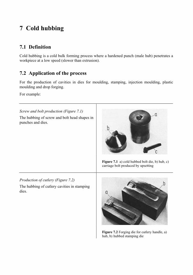
7 Cold hubbing
7.1 Definition Cold hubbing is a cold bulk forming process where a hardened punch (male hub) penetrates a workpiece at a low speed (slower than extrusion).
7.2 Application of the process For the production of cavities in dies for moulding, stamping, injection moulding, plastic moulding and drop forging.
For example:
Screw and bolt production (Figure 7.1)The hubbing of screw and bolt head shapes in punches and dies.
Figure 7.1 a) cold hubbed bolt die, b) hub, c) carriage bolt produced by upsetting
Production of cutlery (Figure 7.2)The hubbing of cutlery cavities in stamping dies.
Figure 7.2 Forging die for cutlery handle, a) hub, b) hubbed stamping die
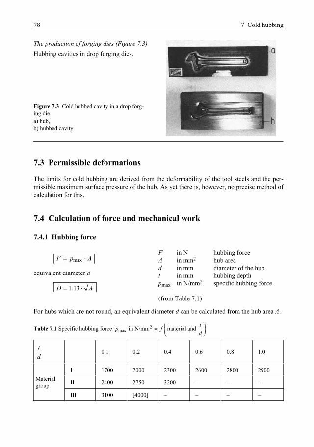
78 7 Cold hubbing
The production of forging dies (Figure 7.3)Hubbing cavities in drop forging dies.
Figure 7.3 Cold hubbed cavity in a drop forg-ing die, a) hub,b) hubbed cavity
7.3 Permissible deformations
The limits for cold hubbing are derived from the deformability of the tool steels and the per-missible maximum surface pressure of the hub. As yet there is, however, no precise method of calculation for this.
7.4 Calculation of force and mechanical work
7.4.1 Hubbing force
maxF p A
equivalent diameter d
1.13 D A
F in N hubbing force A in mm2 hub area d in mm diameter of the hub t in mm hubbing depth pmax in N/mm2 specific hubbing force
(from Table 7.1)
For hubs which are not round, an equivalent diameter d can be calculated from the hub area A.
Table 7.1 Specific hubbing force 2max in N/mm material and tp f
d
td
0.1 0.2 0.4 0.6 0.8 1.0
I 1700 2000 2300 2600 2800 2900
II 2400 2750 3200 – – – Material group
III 3100 [4000] – – – –
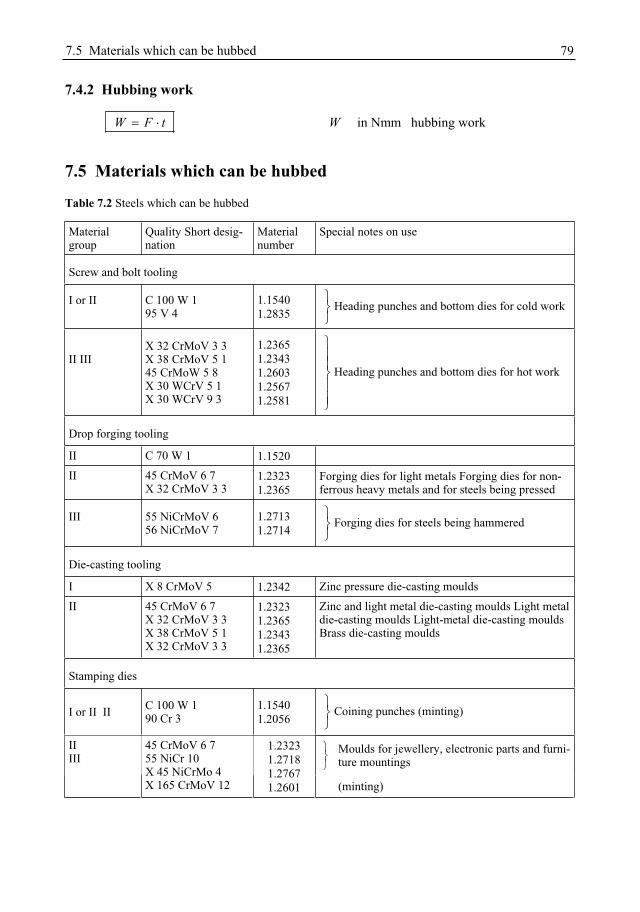
79
7.4.2 Hubbing work
W F t W in Nmm hubbing work
7.5 Materials which can be hubbed
Table 7.2 Steels which can be hubbed
Material group
Quality Short desig-nation
Material number
Special notes on use
Screw and bolt tooling
I or II C 100 W 1 95 V 4
1.15401.2835 Heading punches and bottom dies for cold work
II III X 32 CrMoV 3 3 X 38 CrMoV 5 1 45 CrMoW 5 8 X 30 WCrV 5 1 X 30 WCrV 9 3
1.23651.23431.26031.25671.2581
Heading punches and bottom dies for hot work
Drop forging tooling
II C 70 W 1 1.1520II 45 CrMoV 6 7
X 32 CrMoV 3 3 1.23231.2365
Forging dies for light metals Forging dies for non-ferrous heavy metals and for steels being pressed
III 55 NiCrMoV 6 56 NiCrMoV 7
1.27131.2714 Forging dies for steels being hammered
Die-casting tooling
I X 8 CrMoV 5 1.2342 Zinc pressure die-casting moulds
II 45 CrMoV 6 7 X 32 CrMoV 3 3 X 38 CrMoV 5 1 X 32 CrMoV 3 3
1.23231.23651.23431.2365
Zinc and light metal die-casting moulds Light metal die-casting moulds Light-metal die-casting moulds Brass die-casting moulds
Stamping dies
I or II II C 100 W 1 90 Cr 3
1.15401.2056 Coining punches (minting)
Moulds for jewellery, electronic parts and furni-ture mountings
IIIII
45 CrMoV 6 7 55 NiCr 10 X 45 NiCrMo 4 X 165 CrMoV 12
1.23231.27181.27671.2601 (minting)
7.5 Materials which can be hubbed
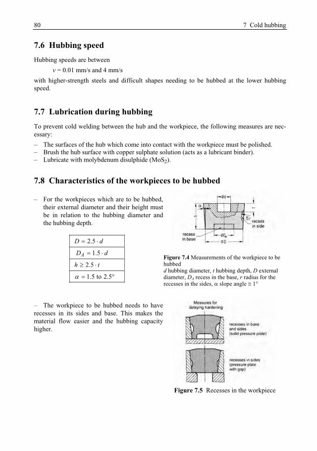
80 7 Cold hubbing
7.6 Hubbing speed Hubbing speeds are between
v = 0.01 mm/s and 4 mm/s with higher-strength steels and difficult shapes needing to be hubbed at the lower hubbing speed.
7.7 Lubrication during hubbing To prevent cold welding between the hub and the workpiece, the following measures are nec-essary:– The surfaces of the hub which come into contact with the workpiece must be polished. – Brush the hub surface with copper sulphate solution (acts as a lubricant binder). – Lubricate with molybdenum disulphide (MoS2).
7.8 Characteristics of the workpieces to be hubbed
– For the workpieces which are to be hubbed, their external diameter and their height must be in relation to the hubbing diameter and the hubbing depth.
2.5 D d
1.5 AD d
2.5 h t
1.5 to 2.5
– The workpiece to be hubbed needs to have recesses in its sides and base. This makes the material flow easier and the hubbing capacity higher.
Figure 7.4 Measurements of the workpiece to be hubbedd hubbing diameter, t hubbing depth, D external diameter, DA recess in the base, r radius for the recesses in the sides, slope angle 1°
Figure 7.5 Recesses in the workpiece
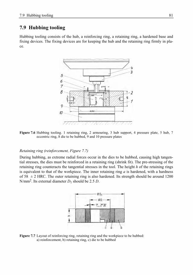
7.9 Hubbing tooling 81
7.9 Hubbing tooling Hubbing tooling consists of the hub, a reinforcing ring, a retaining ring, a hardened base and fixing devices. The fixing devices are for keeping the hub and the retaining ring firmly in pla-ce.
Figure 7.6 Hubbing tooling. 1 retaining ring, 2 armouring, 3 hub support, 4 pressure plate, 5 hub, 7 eccentric ring, 8 die to be hubbed, 9 and 10 pressure plates
Retaining ring (reinforcement, Figure 7.7)During hubbing, as extreme radial forces occur in the dies to be hubbed, causing high tangen-tial stresses, the dies must be reinforced in a retaining ring (shrink fit). The pre-stressing of the retaining ring counteracts the tangential stresses in the tool. The height h of the retaining rings is equivalent to that of the workpiece. The inner retaining ring a is hardened, with a hardness of 58 ± 2 HRC. The outer retaining ring is also hardened. Its strength should be around 1200 N/mm2. Its external diameter D1 should be 2.5 D.
Figure 7.7 Layout of reinforcing ring, retaining ring and the workpiece to be hubbed: a) reinforcement, b) retaining ring, c) die to be hubbed
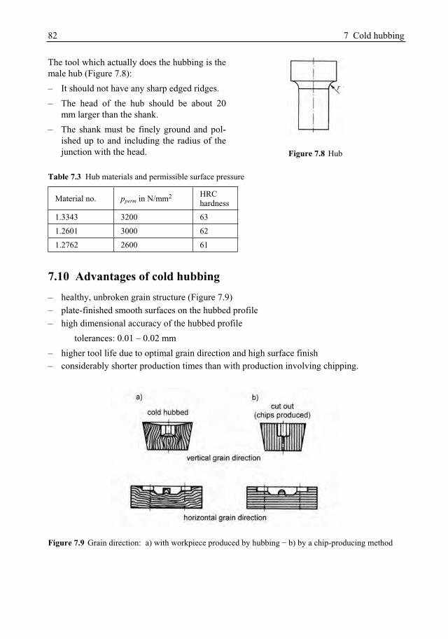
82 7 Cold hubbing
The tool which actually does the hubbing is the male hub (Figure 7.8): – It should not have any sharp edged ridges. – The head of the hub should be about 20
mm larger than the shank. – The shank must be finely ground and pol-
ished up to and including the radius of the junction with the head. Figure 7.8 Hub
Table 7.3 Hub materials and permissible surface pressure
Material no. pperm in N/mm2 HRChardness
1.3343 3200 63
1.2601 3000 62
1.2762 2600 61
7.10 Advantages of cold hubbing – healthy, unbroken grain structure (Figure 7.9) – plate-finished smooth surfaces on the hubbed profile – high dimensional accuracy of the hubbed profile
tolerances: 0.01 – 0.02 mm – higher tool life due to optimal grain direction and high surface finish – considerably shorter production times than with production involving chipping.
Figure 7.9 Grain direction: a) with workpiece produced by hubbing b) by a chip-producing method
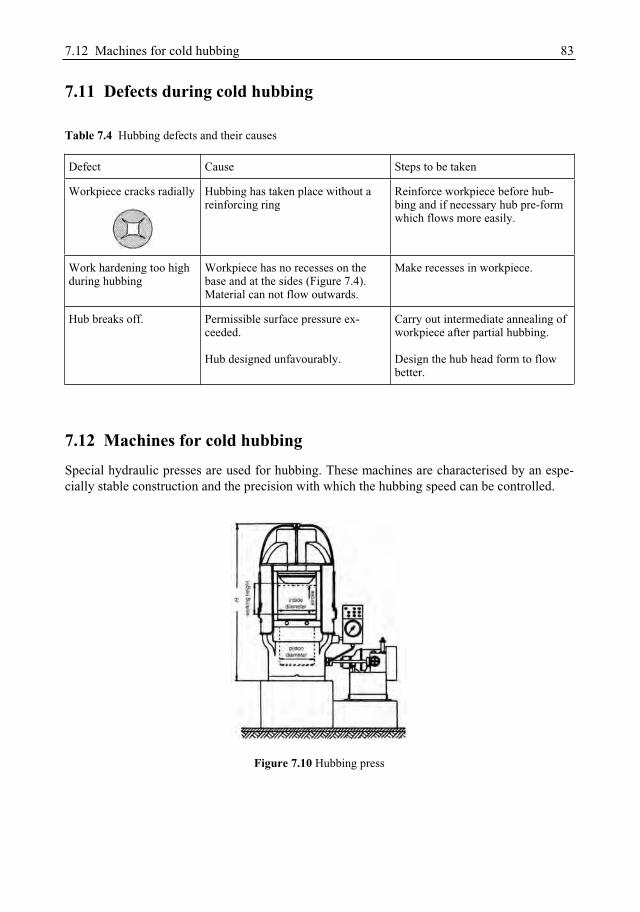
7.12 Machines for cold hubbing 83
7.11 Defects during cold hubbing
Table 7.4 Hubbing defects and their causes
Defect Cause Steps to be taken
Workpiece cracks radially Hubbing has taken place without a reinforcing ring
Reinforce workpiece before hub-bing and if necessary hub pre-form which flows more easily.
Work hardening too high during hubbing
Workpiece has no recesses on the base and at the sides (Figure 7.4). Material can not flow outwards.
Make recesses in workpiece.
Hub breaks off. Permissible surface pressure ex-ceeded.
Hub designed unfavourably.
Carry out intermediate annealing of workpiece after partial hubbing.
Design the hub head form to flow better.
7.12 Machines for cold hubbing Special hydraulic presses are used for hubbing. These machines are characterised by an espe-cially stable construction and the precision with which the hubbing speed can be controlled.
Figure 7.10 Hubbing press
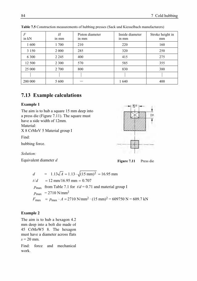
84 7 Cold hubbing
Table 7.5 Construction measurements of hubbing presses (Sack und Kiesselbach manufacturers)
Fin kN
Hin mm
Piston diameter in mm
Inside diameter in mm
Stroke height in mm
1 600 1 700 210 220 160
3 150 2 000 285 320 250
6 300 2 245 400 415 275
12 500 2 300 570 585 355
25 000 2 700 800 830 380
200 000 5 600 – 1 640 400
7.13 Example calculations Example 1 The aim is to hub a square 15 mm deep into a press die (Figure 7.11). The square must have a side width of 12mm. Material:X 8 CrMoV 5 Material group I Find: hubbing force.
Solution:Equivalent diameter d Figure 7.11 Press die
d = 21.13 1.13 (15 mm) 16.95 mmAt /d 12 mm/16.95 mm 0.707
maxp from Table 7.1 for t/d = 0.71 and material group I
maxp = 2710 N/mm2
Fmax maxp A 2710 N/mm2 · (15 mm)2 = 609750 N = 609.7 kN
Example 2 The aim is to hub a hexagon 4.2 mm deep into a bolt die made of45 CrMoW5 8. The hexagon must have a diameter across flats s = 20 mm. Find: force and mechanical work.

7.14 Exercise on Chapter 7 85
Solution:
62
a hA
where 10 mm2sh
22 2
4aa h
4 4 10 11.54 mm3 3
a hFigure 7.12 Hexagon with
measurements
211.54 106 6 = 346.2 mm2 2
a hA
eq. 1.13 1.13 346.2 21.0 mmd A
2 2max 3
4000 N/mm 346.2 mm 1384.8 kN10
F p A
4.2 0.221
td
1384.8 kN 0.0042 m = 5.8 kNmW F t
7.14 Exercise on Chapter 7 1. What is meant by “cold hubbing”? 2. What is this method used for? 3. Describe the hubbing tooling. 4. What has gone wrong if the workpiece cracks during hubbing? 5. What are the advantages of cold hubbing? 6. What are the advantages of the cold hubbing process compared to a chip-producing manu-
facturing process when producing a bolt die with a hexagon cavity?
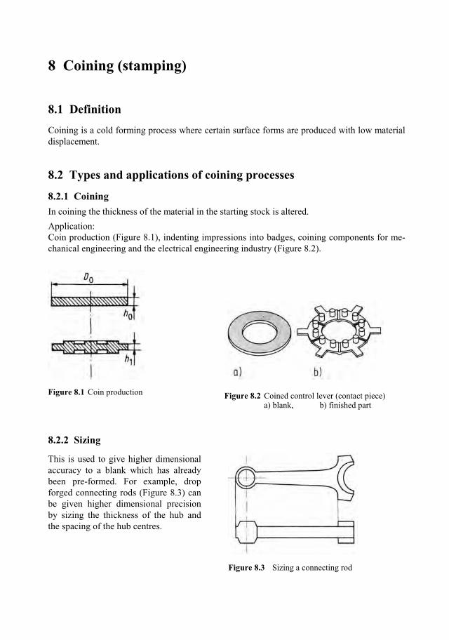
8 Coining (stamping)
8.1 Definition Coining is a cold forming process where certain surface forms are produced with low material displacement.
8.2 Types and applications of coining processes
8.2.1 Coining In coining the thickness of the material in the starting stock is altered. Application: Coin production (Figure 8.1), indenting impressions into badges, coining components for me-chanical engineering and the electrical engineering industry (Figure 8.2).
Figure 8.1 Coin production Figure 8.2 Coined control lever (contact piece) a) blank, b) finished part
8.2.2 Sizing
This is used to give higher dimensional accuracy to a blank which has already been pre-formed. For example, drop forged connecting rods (Figure 8.3) can be given higher dimensional precision by sizing the thickness of the hub and the spacing of the hub centres.
Figure 8.3 Sizing a connecting rod
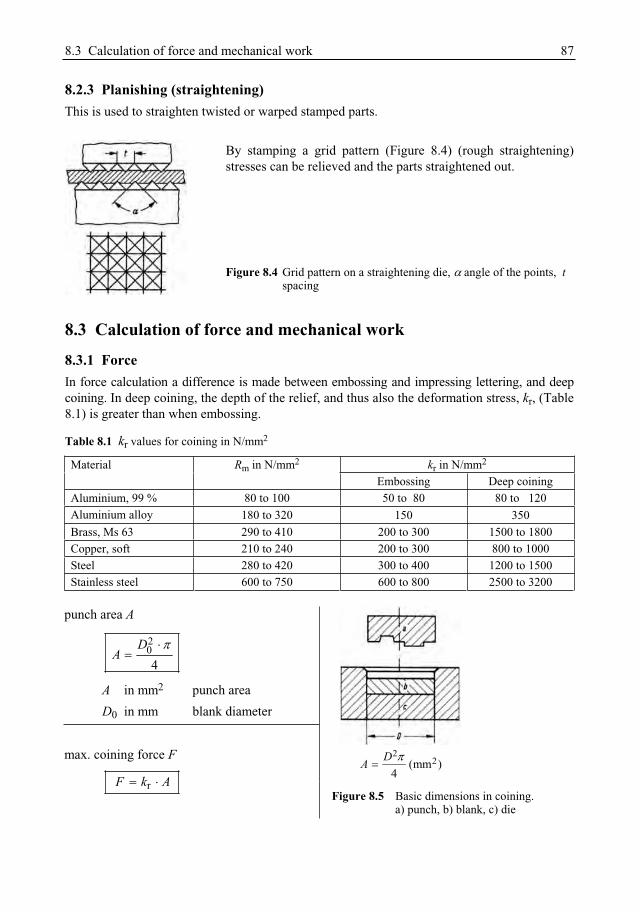
8.3 Calculation of force and mechanical work 87
8.2.3 Planishing (straightening) This is used to straighten twisted or warped stamped parts.
By stamping a grid pattern (Figure 8.4) (rough straightening) stresses can be relieved and the parts straightened out.
Figure 8.4 Grid pattern on a straightening die, angle of the points, tspacing
8.3 Calculation of force and mechanical work
8.3.1 Force In force calculation a difference is made between embossing and impressing lettering, and deep coining. In deep coining, the depth of the relief, and thus also the deformation stress, kr, (Table 8.1) is greater than when embossing.
Table 8.1 kr values for coining in N/mm2
Material Rm in N/mm2 kr in N/mm2
Embossing Deep coining Aluminium, 99 % 80 to 100 50 to 80 80 to 120 Aluminium alloy 180 to 320 150 350Brass, Ms 63 290 to 410 200 to 300 1500 to 1800 Copper, soft 210 to 240 200 to 300 800 to 1000 Steel 280 to 420 300 to 400 1200 to 1500 Stainless steel 600 to 750 600 to 800 2500 to 3200
punch area A
204
DA
A in mm2 punch area D0 in mm blank diameter
22(mm )
4DA
max. coining force F
rF k A Figure 8.5 Basic dimensions in coining.
a) punch, b) blank, c) die
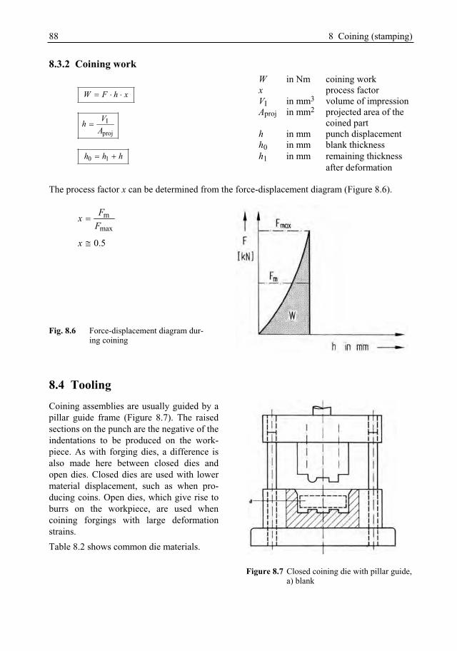
88 8 Coining (stamping)
8.3.2 Coining work
W F h x
I
proj
VhA
0 1h h h
W in Nm coining work x process factor VI in mm3 volume of impression Aproj in mm2 projected area of the
coined part h in mm punch displacement h0 in mm blank thickness h1 in mm remaining thickness
after deformation
The process factor x can be determined from the force-displacement diagram (Figure 8.6).
m
max
FxF
0.5x
Fig. 8.6 Force-displacement diagram dur-ing coining
8.4 Tooling Coining assemblies are usually guided by a pillar guide frame (Figure 8.7). The raised sections on the punch are the negative of the indentations to be produced on the work-piece. As with forging dies, a difference is also made here between closed dies and open dies. Closed dies are used with lower material displacement, such as when pro-ducing coins. Open dies, which give rise to burrs on the workpiece, are used when coining forgings with large deformation strains.Table 8.2 shows common die materials.
Figure 8.7 Closed coining die with pillar guide, a) blank
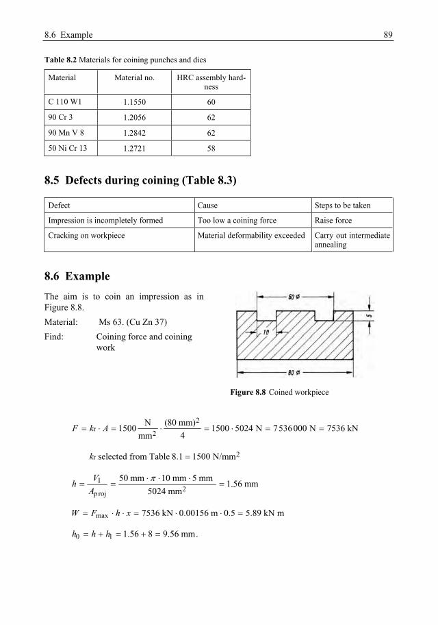
8.6 Example 89
Table 8.2 Materials for coining punches and dies
Material Material no. HRC assembly hard-ness
C 110 W1 1.1550 60
90 Cr 3 1.2056 62
90 Mn V 8 1.2842 62
50 Ni Cr 13 1.2721 58
8.5 Defects during coining (Table 8.3)
Defect Cause Steps to be taken
Impression is incompletely formed Too low a coining force Raise force
Cracking on workpiece Material deformability exceeded Carry out intermediate annealing
8.6 Example The aim is to coin an impression as in Figure 8.8. Material: Ms 63. (Cu Zn 37) Find: Coining force and coining
work
Figure 8.8 Coined workpiece
2r 2
N (80 mm)1500 1500 5024 N 7536000 N 7536 kN4mm
F k A
2r selected from Table 8.1 1500 N/mmk
I2p roj
50 mm 10 mm 5 mm 1.56 mm5024 mm
VhA
max 7536 kN 0.00156 m 0.5 5.89 kN mW F h x
0 1 1.56 8 9.56 mm.h h h

90 8 Coining (stamping)
8.7 Exercise on Chapter 8 1. What is meant by “coining”? 2. What methods of coining are there? 3. What are the main elements of coining dies? 4. What is coining used for millions of times in practice?
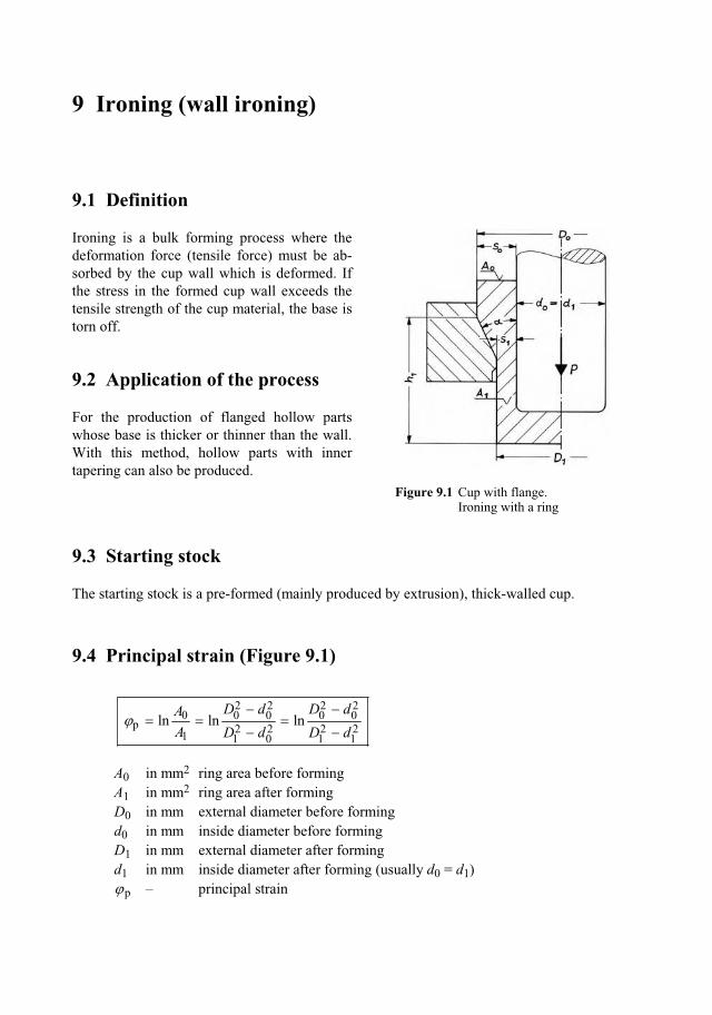
9 Ironing (wall ironing)
9.1 Definition
Ironing is a bulk forming process where the deformation force (tensile force) must be ab-sorbed by the cup wall which is deformed. If the stress in the formed cup wall exceeds the tensile strength of the cup material, the base is torn off.
9.2 Application of the process
For the production of flanged hollow parts whose base is thicker or thinner than the wall. With this method, hollow parts with inner tapering can also be produced.
Figure 9.1 Cup with flange. Ironing with a ring
9.3 Starting stock
The starting stock is a pre-formed (mainly produced by extrusion), thick-walled cup.
9.4 Principal strain (Figure 9.1)
2 2 2 20 0 0 0 0
p 2 2 2 21 1 0 1 1ln ln ln
D d D dAA D d D d
A0 in mm2 ring area before forming A1 in mm2 ring area after forming D0 in mm external diameter before forming d0 in mm inside diameter before forming D1 in mm external diameter after forming d1 in mm inside diameter after forming (usually d0 = d1)
p – principal strain
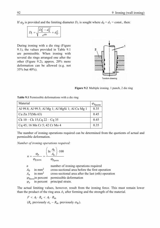
92 9 Ironing (wall ironing)
If p is provided and the limiting diameter D1 is sought where d0 = d1 = const., then:
p
2 20 0 21 0 .
D dD d
e
During ironing with a die ring (Figure 9.1), the values provided in Table 9.1 are permissible. When ironing with several die rings arranged one after the other (Figure 9.2), approx. 20% more deformation can be allowed (e.g. not 35% but 40%).
Figure 9.2 Multiple ironing. 1 punch, 2 die ring
Table 9.1 Permissible deformations with a die ring
Material ppermAl 99.8; Al 99.5; Al Mg 1; Al MgSi 1; Al Cu Mg 1 0.35
Cu Zn 37(Ms 63) 0.45
Ck 10 – Ck 15,Cq 22 – Cq 35 0.45
Cq 45; 16 Mn Cr 5; 42 Cr Mo 4 0.35
The number of ironing operations required can be determined from the quotients of actual and permissible deformation.
Number of ironing operations required:
perm perm
0p n
p p
ln 100AA
n
n number of ironing operations required A0 in mm2 cross-sectional area before the first operation An in mm2 cross-sectional area after the last (nth) operation
ppermin percent permissible deformation p in percent principal strain.
The actual limiting values, however, result from the ironing force. This must remain lower than the product of the ring area A1 after forming and the strength of the material.
1 e 1 mF A R A R
e s m B( previously previously ).R R
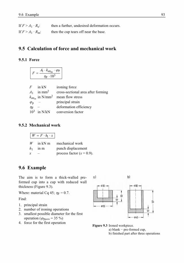
9.6 Example 93
If F > A1 · Re: then a further, undesired deformation occurs. If F > A1 · Rm: then the cup tears off near the base.
9.5 Calculation of force and mechanical work
9.5.1 Force
m p1 str3F 10
A kF
F in kN ironing force A1 in mm2 cross-sectional area after forming kstrm in N/mm2 mean flow stress
p – principal strain F – deformation efficiency
103 in N/kN conversion factor
9.5.2 Mechanical work
1W F h x
W in kN m mechanical work h1 in m punch displacement x – process factor (x = 0.9).
9.6 Example
The aim is to form a thick-walled pre-formed cup into a cup with reduced wall thickness (Figure 9.3). Where: material Cq 45; F = 0.7. Find: 1. principal strain 2. number of ironing operations 3. smallest possible diameter for the first
operation ( pperm = 35 %) 4. force for the first operation
Figure 9.3 Ironed workpiece. a) blank pre-formed cup, b) finished part after three operations

94 9 Ironing (wall ironing)
Solution:
Principal strain:
2 2 2 2 2 20 0
p 2 2 2 2 2 21 0
50 mm 30 mmln ln 0.82.40 mm 30 mm
D dD d
Number of ironing operations required:
perm
p
p
82 % 2.3435 %
n
n = 3 operations required. (Repeated soft annealing required after each operation.)
Smallest possible diameter for the first operation:
h
2 2 2 2 2 20 0 2 21 0 0.3550 mm 30 mm 30 mm
D dD d
e e
1 min1600 900 45 mm .1.419
D
Force for the first operation: For p = 35 %: kstr0 = 390 N/mm2; kstr1 = 860 N/mm2; kstrm = 625 N/mm2.During the first operation, D1 = 45 mm, d0 = d1 = 30 mm
m m2 21 str p str p1 0
3 3F F
( )10 4 10
A k D d kF
2 2 2 2 2
3(45 mm 30 mm ) 625 N/ mm 0.35 276 kN .
4 0.7 10F
9.7 Exercise on Chapter 9
1. How does ironing differ from forward extrusion? 2. What limits the extent of the deformation? 3. What workpiece shapes is it used for?
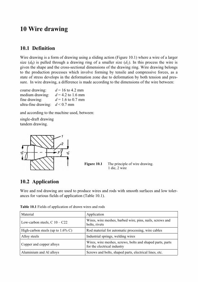
10 Wire drawing
10.1 Definition Wire drawing is a form of drawing using a sliding action (Figure 10.1) where a wire of a larger size (d0) is pulled through a drawing ring of a smaller size (d1). In this process the wire is given the shape and the cross-sectional dimensions of the drawing ring. Wire drawing belongs to the production processes which involve forming by tensile and compressive forces, as a state of stress develops in the deformation zone due to deformation by both tension and pres-sure. In wire drawing, a difference is made according to the dimensions of the wire between:
coarse drawing: d = 16 to 4.2 mm medium drawing: d = 4.2 to 1.6 mm fine drawing: d = 1.6 to 0.7 mm ultra-fine drawing: d < 0.7 mm
and according to the machine used, between: single-draft drawing tandem drawing.
Figure 10.1 The principle of wire drawing. 1 die, 2 wire
10.2 Application Wire and rod drawing are used to produce wires and rods with smooth surfaces and low toler-ances for various fields of application (Table 10.1).
Table 10.1 Fields of application of drawn wires and rods
Material Application
Low-carbon steels, C 10 – C22 Wires, wire meshes, barbed wire, pins, nails, screws and bolts, rivets
High-carbon steels (up to 1.6% C) Rod material for automatic processing, wire cables Alloy steels Industrial springs, welding wires
Copper and copper alloys Wires, wire meshes, screws, bolts and shaped parts, parts for the electrical industry
Aluminium and Al alloys Screws and bolts, shaped parts, electrical lines, etc.

96 10 Wire drawing
10.3 Starting stock The starting stock for wire drawing is hot-rolled wires. For rod drawing, rods produced by hot rolling or extrusion moulding are used as starting stock.
10.4 Principal strain The principal strain results from the aspect ratio before and after drawing.
p 0
1ln A
A
p0
1 /2dd
e
A0 in mm2 cross-section before drawing A1 in mm2 cross-section after drawing d0 in mm diameter before drawing d1 in mm diameter after drawing e = 2.718 basic number of the natural logarithm
p principal strain
10.5 Permissible deformations The following table contains standard values for the drawing reductions and the permissible total deformation in tandem drawing.
Table 10.2 Permissible deformations with tandem drawing
Mate-rial
Intake strength Rm
in N/mm2
Intake diameter d0
in mm
Drawing reduc-tion between two draws
pperm (%)
Total deformation (tandem drawing)
pperm (%)
Number of drawing sta-tions
400 4 – 12 18 – 22 380 – 400
1200 4 – 12 18 – 22 380 – 400
Stee
l wire
1200 0.5 – 2.5 12 – 15 120 – 150
8to21
8 – 10 wet draws 40 – 50 350 – 400
Cu
mat
eri-
als
Cu (soft)
250 1 – 3.5 18 – 20 200 – 300
5to13
12 – 16 wet draws 20 – 25 250 – 300
Al m
ate-
rials
Al (soft) and Al alloy
80 1 – 3.5 15 – 20 150 – 200
5to13

10.7 Drawing speeds 97
In single drawing, the permissible deformations are around:
– Steel wires = 150 – 200 % – Cu materials = 200 %
(Cu soft) – Al materials = 200 %
(Al soft).
10.6 Drawing force
According to Siebel, the drawing force can be calculated with the following equation
m pdr 1 strp
2 1 .3
F A k
The mean coefficient of friction is around = 0.035 ( = 0.02 to 0.05). The optimum drawing angle, requiring the least force, is around 2 = 16º. From this it follows for the angle in radi-ans:
8 0.13180 180
.
If these values are brought into the above equation, then the drawing force during wire draw-ing can be determined approximately with the simplified equation and the deformation effi-ciency = 0.6.
m1 str pdr
F
A kF
Fdr in N drawing force kstrm in N/mm2 mean flow stress A1 in mm2 cross-section of the wire after drawing
p – principal strain F – deformation efficiency ( F = 0.6).
10.7 Drawing speeds
10.7.1 Single-draft drawing
The drawing speeds for single-draft drawing can be taken from the following table.

98 10 Wire drawing
Table 10.3 drawing speeds for single-draft draws
Material Intake strength Rm in N/mm2max in m/s
(iron wire) 400
20
800 15Steel wire
1300 10Cu (soft) 250 Brass, bronze 400
20
Al and Al alloys 80 – 100 25
10.7.2 Tandem drawing In tandem drawing, the drawing speed differs at every drawing. As the volume is constant, the speed is higher when the wire cross-section is reduced.
1 · Al = 2 · A2
1 · Al = n · An
n n1
1
AA
1 in m/s drawing speed at the first draw 2 in m/s drawing speed at the 2nd draw n in m/s drawing speed at the nth draw
A1 in mm2 wire cross-section after the 1st draw A2 in mm2 wire cross-section after the 2nd draw An in mm2 wire cross-section after the nth draw
In tables of standard values, the highest speeds, applying to the last drawing, are always listed for tandem drawing machines.
Table 10.4 Drawing speed n for tandem drawing
Material Intake strength Rm in N/mm2n in m/s
(iron wire) 400
20
800 15Steel wire
1300 10Cu (soft) 250 Brass, bronze 400 Al (soft), Al alloys 80 – 100
25
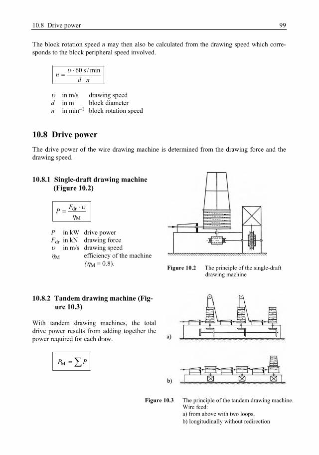
10.8 Drive power 99
The block rotation speed n may then also be calculated from the drawing speed which corre-sponds to the block peripheral speed involved.
60 s / minnd
in m/s drawing speed d in m block diameter n in min–1 block rotation speed
10.8 Drive power The drive power of the wire drawing machine is determined from the drawing force and the drawing speed.
10.8.1 Single-draft drawing machine (Figure 10.2)
dr
M
FP
P in kW drive power Fdr in kN drawing force
in m/s drawing speed M efficiency of the machine
( M = 0.8). Figure 10.2 The principle of the single-draft
drawing machine
10.8.2 Tandem drawing machine (Fig-ure 10.3)
With tandem drawing machines, the total drive power results from adding together the power required for each draw.
MP P
Figure 10.3 The principle of the tandem drawing machine. Wire feed: a) from above with two loops, b) longitudinally without redirection
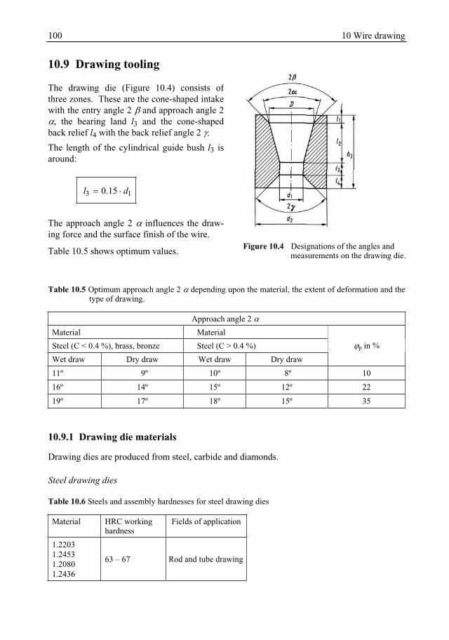
100 10 Wire drawing
10.9 Drawing tooling
The drawing die (Figure 10.4) consists ofthree zones. These are the cone-shaped intake with the entry angle 2 and approach angle 2
, the bearing land l3 and the cone-shaped back relief l4 with the back relief angle 2 .The length of the cylindrical guide bush l3 isaround:
3 10.15l d
The approach angle 2 influences the draw-ing force and the surface finish of the wire.
Table 10.5 shows optimum values. Figure 10.4 Designations of the angles and measurements on the drawing die.
Table 10.5 Optimum approach angle 2 depending upon the material, the extent of deformation and the type of drawing.
Approach angle 2 Material Material Steel (C < 0.4 %), brass, bronze Steel (C > 0.4 %) Wet draw Dry draw Wet draw Dry draw
p in %
11º 9º 10º 8º 10
16º 14º 15º 12º 22
19º 17º 18º 15º 35
10.9.1 Drawing die materials
Drawing dies are produced from steel, carbide and diamonds.
Steel drawing dies
Table 10.6 Steels and assembly hardnesses for steel drawing dies
Material HRC working hardness
Fields of application
1.22031.24531.20801.2436
63 – 67 Rod and tube drawing
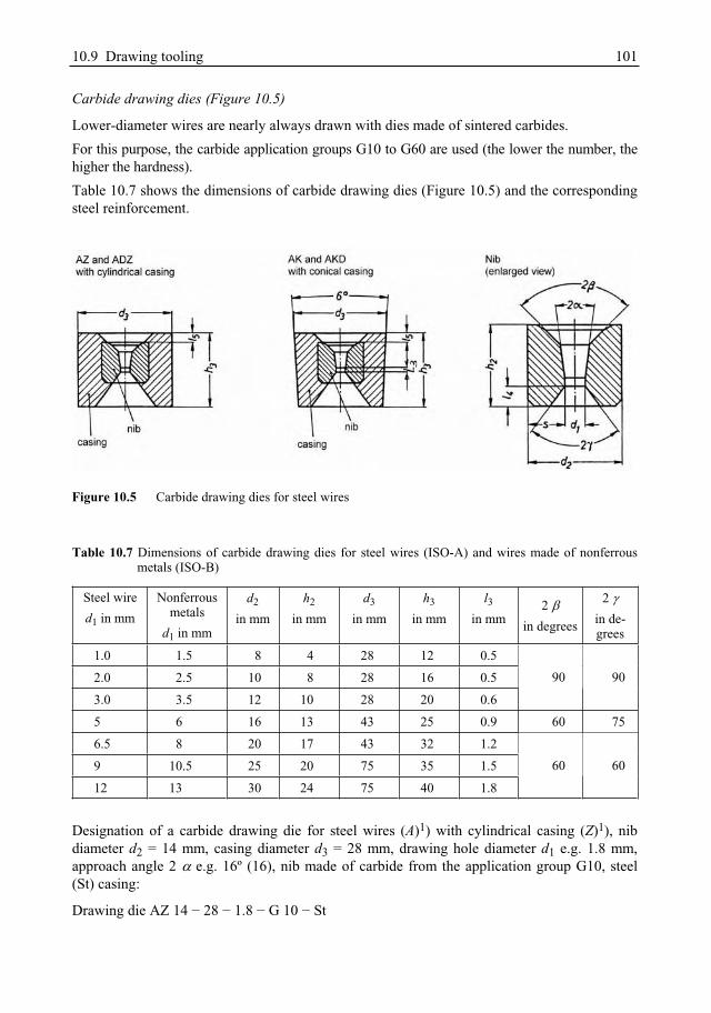
10.9 Drawing tooling 101
Carbide drawing dies (Figure 10.5)
Lower-diameter wires are nearly always drawn with dies made of sintered carbides. For this purpose, the carbide application groups G10 to G60 are used (the lower the number, the higher the hardness). Table 10.7 shows the dimensions of carbide drawing dies (Figure 10.5) and the corresponding steel reinforcement.
Figure 10.5 Carbide drawing dies for steel wires
Table 10.7 Dimensions of carbide drawing dies for steel wires (ISO-A) and wires made of nonferrous metals (ISO-B)
Steel wire d1 in mm
Nonferrousmetals
d1 in mm
d2
in mm h2
in mm d3
in mm h3
in mm l3
in mm 2
in degrees
2in de-grees
1.0 1.5 8 4 28 12 0.5
2.0 2.5 10 8 28 16 0.5
3.0 3.5 12 10 28 20 0.6
90 90
5 6 16 13 43 25 0.9 60 75
6.5 8 20 17 43 32 1.2
9 10.5 25 20 75 35 1.5
12 13 30 24 75 40 1.8
60 60
Designation of a carbide drawing die for steel wires (A)1) with cylindrical casing (Z)1), nib diameter d2 = 14 mm, casing diameter d3 = 28 mm, drawing hole diameter d1 e.g. 1.8 mm, approach angle 2 e.g. 16º (16), nib made of carbide from the application group G10, steel (St) casing:
Drawing die AZ 14 28 1.8 G 10 St
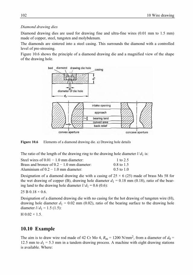
102 10 Wire drawing
Diamond drawing diesDiamond drawing dies are used for drawing fine and ultra-fine wires (0.01 mm to 1.5 mm) made of copper, steel, tungsten and molybdenum. The diamonds are sintered into a steel casing. This surrounds the diamond with a controlled level of pre-stressing. Figure 10.6 shows the principle of a diamond drawing die and a magnified view of the shape of the drawing hole.
Figure 10.6 Elements of a diamond drawing die. a) Drawing hole details
The ratio of the length of the drawing ring to the drawing hole diameter l /d1 is: Steel wires of 0.01 1.0 mm diameter: 1 to 2.5 Brass and bronze of 0.2 1.0 mm diameter: 0.8 to 1.5 Aluminium of 0.2 1.0 mm diameter: 0.5 to 1.0 Designation of a diamond drawing die with a casing of 25 × 6 (25) made of brass Ms 58 for the wet drawing of copper (B), drawing hole diameter d1 = 0.18 mm (0.18), ratio of the bear-ing land to the drawing hole diameter l /d1 = 0.6 (0.6): 25 B 0.18 × 0.6. Designation of a diamond drawing die with no casing for the hot drawing of tungsten wire (H), drawing hole diameter d1 = 0.02 mm (0.02), ratio of the bearing surface to the drawing hole diameter l /d1 = 1.5 (1.5): H 0.02 × 1.5.
10.10 Example The aim is to draw wire rod made of 42 Cr Mo 4, Rm = 1200 N/mm2, from a diameter of d0 = 12.5 mm to d1 = 5.3 mm in a tandem drawing process. A machine with eight drawing stations is available. Where:

10.10 Example 103
max = n = 10 m/s f = 0.6 deformation efficiency M = 0.7 efficiency of the drawing machine.
Find: 1. Total deformation 2. Deformation per draw 3. Intermediate diameter at 2nd to 7th draws where deformation between draws is the same 4. Drawing force for the 1st draw 5. Driving power for the 1st draw. Solution:
1. tot.
20p 31
12.5 / 4ln ln 1.72 172 %5.3 / 4
AA
2. totdraw
pp
172 % 21.5 % per draw8Dr
3. 01 / 2 0.215 / 2 0.175
12.5 12.5 12.5 11.2 mm1.11349
dde e e
12 / 2 10.05 mm etc.dd
e3 4 5 6 7 89.02, 8.10, 7.27, 6.52, 5.85, 5.3d d d d d d
4. Drawing force (1st draw)
m1 k pdr
F
A kF
1p 21.5 % 0.215
0 1 m2 2 2str str str
420 880420 N/ mm , 880 N/ mm , 650 N/ mm2
k k k
2 21 21
(11.2 mm) 98.52 mm4 4
dA
2dr 2
98.52 mm 650 N 0.215 22 946 N 22.9 kN0.6 mm
F
5. Driving power (1st draw) 5.1 Drawing speed (1st draw)
2n n1 21
10 m (5.3 mm) / 4(11.2 mm) / 4
AA
1 2.24 m/s .
5.2 Driving power (1st draw)
dr 11
M
22.9 kN 2.24 m 73.3 kW .0.7 s
FP

104 10 Wire drawing
10.11 Exercise on Chapter 10 1. What methods of wire drawing are there? 2. What kinds of machines for wire drawing are there? 3. How is the principal strain determined in wire drawing? 4. Why are the drawing speeds different at every drawing ring in tandem drawing? 5. What materials are drawing dies made of? 6. Which wires are carbide drawing dies used for?
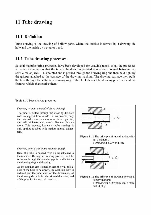
11 Tube drawing
11.1 Definition Tube drawing is the drawing of hollow parts, where the outside is formed by a drawing die hole and the inside by a plug or a rod.
11.2 Tube drawing processes Several manufacturing processes have been developed for drawing tubes. What the processes all have in common is that the tube to be drawn is pointed at one end (pressed between two semi-circular jaws). This pointed end is pushed through the drawing ring and then held tight by the gripper attached to the carriage of the drawing machine. The drawing carriage then pulls the tube through the stationary drawing ring. Table 11.1 shows tube drawing processes and the features which characterise them.
Table 11.1 Tube drawing processes
Drawing without a mandrel (tube sinking) The tube is pulled through the drawing die hole with no support from inside. In this process, only the external diameter measurements are precise; the wall thickness and internal diameter deviate more. This process, known as tube sinking, is only applied to tubes with smaller internal diame-ters.
Figure 11.1 The principle of tube drawing with-out a mandrel. 1 Drawing die, 2 workpiece
Drawing over a stationary mandrel (plug) Here, the tube is pushed over a plug attached to the mandrel. During the drawing process, the tube is drawn through the annular gap formed between the drawing ring and the plug. As the annular gap is smaller than the wall thick-ness of the tube to be drawn, the wall thickness is reduced and the tube takes on the dimensions of the drawing die hole for its external diameter, and of the plug for its internal diameter.
Figure 11.2 The principle of drawing over a sta-tionary mandrel. 1 Drawing ring, 2 workpiece, 3 man-drel, 4 plug
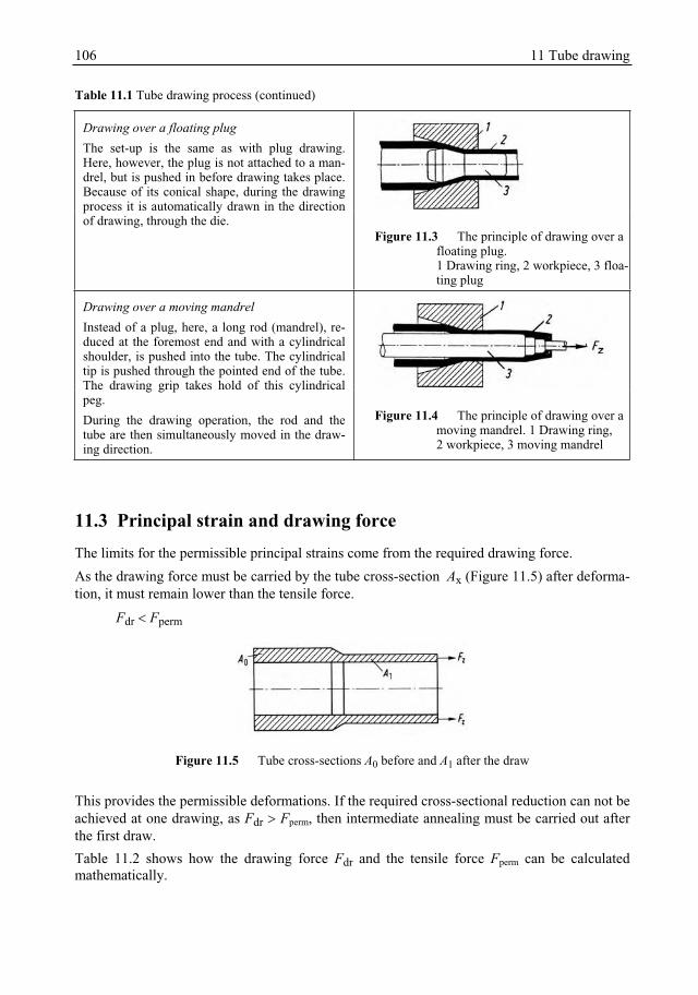
106 11 Tube drawing
Table 11.1 Tube drawing process (continued)
Drawing over a floating plug The set-up is the same as with plug drawing. Here, however, the plug is not attached to a man-drel, but is pushed in before drawing takes place. Because of its conical shape, during the drawing process it is automatically drawn in the direction of drawing, through the die.
Figure 11.3 The principle of drawing over a floating plug.1 Drawing ring, 2 workpiece, 3 floa-ting plug
Drawing over a moving mandrel Instead of a plug, here, a long rod (mandrel), re-duced at the foremost end and with a cylindrical shoulder, is pushed into the tube. The cylindrical tip is pushed through the pointed end of the tube. The drawing grip takes hold of this cylindrical peg.During the drawing operation, the rod and the tube are then simultaneously moved in the draw-ing direction.
Figure 11.4 The principle of drawing over a moving mandrel. 1 Drawing ring,2 workpiece, 3 moving mandrel
11.3 Principal strain and drawing force The limits for the permissible principal strains come from the required drawing force. As the drawing force must be carried by the tube cross-section Ax (Figure 11.5) after deforma-tion, it must remain lower than the tensile force.
Fdr Fperm
Figure 11.5 Tube cross-sections A0 before and A1 after the draw
This provides the permissible deformations. If the required cross-sectional reduction can not be achieved at one drawing, as Fdr Fperm, then intermediate annealing must be carried out after the first draw. Table 11.2 shows how the drawing force Fdr and the tensile force Fperm can be calculated mathematically.

11.4 Drawing tooling 107
Table 11.2 Calculating principal strain and drawing force
Drawing force in N Type of drawing Permissible deforma-tion pperm in % (from drawing force)
Principal strain p (–)
Tube sinking 20 – 50 p = ln 0
1
dd
p% = p · 100 (%)
Plug drawing 30 – 50
m1 str pdr
F
A kF
for 2 = 16° (optimum opening angle):
F = 0.4 – 0.6 for p = 15 %
F = 0.7 – 0.8 for p = 50 %
perm 1 mF A R
Rod drawing 40 – 60
p = ln 0
1
AA
p = ln2 20 02 21 1
D dD d
p(%) = p · 100 (%) Fdr must be lower than Fperm, how-ever, or the tube breaks off.
p – principal strain D0 in mm external diameter before drawing d0 in mm internal diameter before drawing A0 in mm2 tube cross-section before drawing D1 in mm external diameter after drawing d1 in mm internal diameter after drawing A1 in mm2 tube diameter after drawing
kstrm in N/mm2
Rm in N/mm2
Fdr in N Fperm in N
F
mean flow stress
tensile strength of the tube mate-rialdrawing force maximum force which can be carried into the tube cross-sectiondeformation resistance
11.4 Drawing tooling Drawing tooling made of carbide is mainly used for tube drawing. The drawing die is similar in construction to those shown in Figure 10.5 for wire drawing. The drawing mandrel consists of the steel body (Figure 11.6) and the actual mandrel made of carbide. Once more, G10 to G60 are common carbide types used.
Figure 11.6 Drawing mandrel with screwed-on carbide ring

108 11 Tube drawing
11.5 Example The aim is to draw a tube made of Ck 45 (Rm = 800 N/mm2) with initial dimensions of D0 =45, d0 = 30, bringing it to D1 = 40 und d1 = 28.
Find:1. Drawing force 2. Permissible limiting force 3. Can the cross-sectional reduction be achieved in one drawing?
Solution: 2 2 2 20 0
p 2 2 2 21 1
45 30ln ln 0.32 32%40 28
D dD d
m02str str1 str390, 840, 615 N/mmk k k
m2 2 21 str p
dr 2F
(40 28 ) mm 615 N 0.324 0.7 mm
A kF
Fdr = 180 178 N 180 kN
21 mperm 3 3 2
640.9 mm 800 N 512.7 kN10 N/kN 10 N/kN mm
A RF
As Fdr is considerably smaller than Fperm, this deformation can take place in one drawing.
11.6 Exercise on Chapter 11 1. What kinds of tube drawing processes are there? 2. How do they differ from one another?
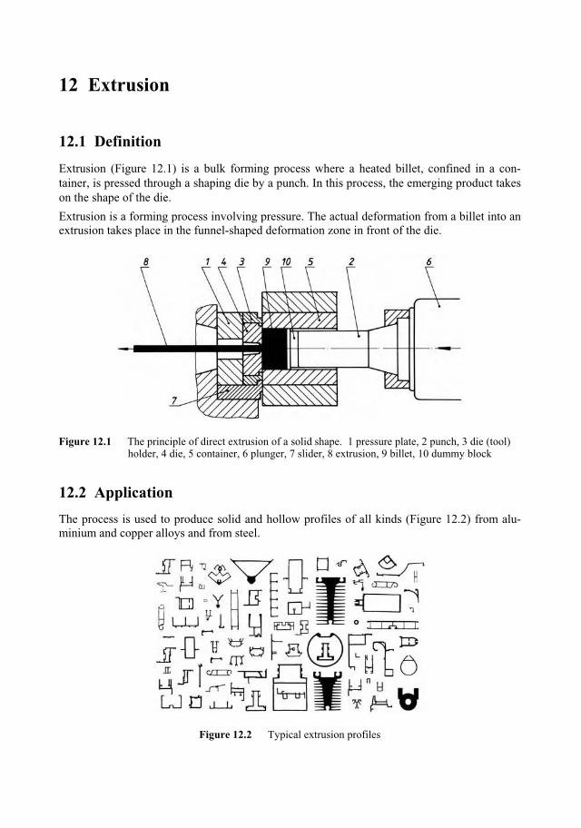
12 Extrusion
12.1 Definition Extrusion (Figure 12.1) is a bulk forming process where a heated billet, confined in a con-tainer, is pressed through a shaping die by a punch. In this process, the emerging product takes on the shape of the die. Extrusion is a forming process involving pressure. The actual deformation from a billet into an extrusion takes place in the funnel-shaped deformation zone in front of the die.
Figure 12.1 The principle of direct extrusion of a solid shape. 1 pressure plate, 2 punch, 3 die (tool) holder, 4 die, 5 container, 6 plunger, 7 slider, 8 extrusion, 9 billet, 10 dummy block
12.2 Application The process is used to produce solid and hollow profiles of all kinds (Figure 12.2) from alu-minium and copper alloys and from steel.
Figure 12.2 Typical extrusion profiles
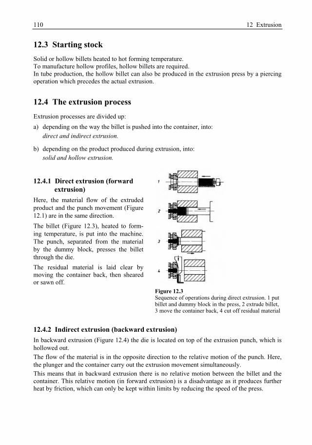
110 12 Extrusion
12.3 Starting stock Solid or hollow billets heated to hot forming temperature. To manufacture hollow profiles, hollow billets are required. In tube production, the hollow billet can also be produced in the extrusion press by a piercing operation which precedes the actual extrusion.
12.4 The extrusion process Extrusion processes are divided up: a) depending on the way the billet is pushed into the container, into:
direct and indirect extrusion.
b) depending on the product produced during extrusion, into: solid and hollow extrusion.
12.4.1 Direct extrusion (forward extrusion)
Here, the material flow of the extruded product and the punch movement (Figure 12.1) are in the same direction. The billet (Figure 12.3), heated to form-ing temperature, is put into the machine. The punch, separated from the material by the dummy block, presses the billet through the die. The residual material is laid clear by moving the container back, then sheared or sawn off.
Figure 12.3 Sequence of operations during direct extrusion. 1 put billet and dummy block in the press, 2 extrude billet, 3 move the container back, 4 cut off residual material
12.4.2 Indirect extrusion (backward extrusion) In backward extrusion (Figure 12.4) the die is located on top of the extrusion punch, which is hollowed out. The flow of the material is in the opposite direction to the relative motion of the punch. Here, the plunger and the container carry out the extrusion movement simultaneously. This means that in backward extrusion there is no relative motion between the billet and the container. This relative motion (in forward extrusion) is a disadvantage as it produces further heat by friction, which can only be kept within limits by reducing the speed of the press.
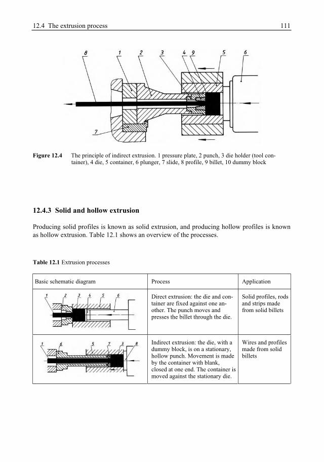
12.4 The extrusion process 111
Figure 12.4 The principle of indirect extrusion. 1 pressure plate, 2 punch, 3 die holder (tool con-tainer), 4 die, 5 container, 6 plunger, 7 slide, 8 profile, 9 billet, 10 dummy block
12.4.3 Solid and hollow extrusion
Producing solid profiles is known as solid extrusion, and producing hollow profiles is known as hollow extrusion. Table 12.1 shows an overview of the processes.
Table 12.1 Extrusion processes
Basic schematic diagram Process Application
Direct extrusion: the die and con-tainer are fixed against one an-other. The punch moves and presses the billet through the die.
Solid profiles, rods and strips made from solid billets
Indirect extrusion: the die, with a dummy block, is on a stationary, hollow punch. Movement is made by the container with blank, closed at one end. The container is moved against the stationary die.
Wires and profiles made from solid billets
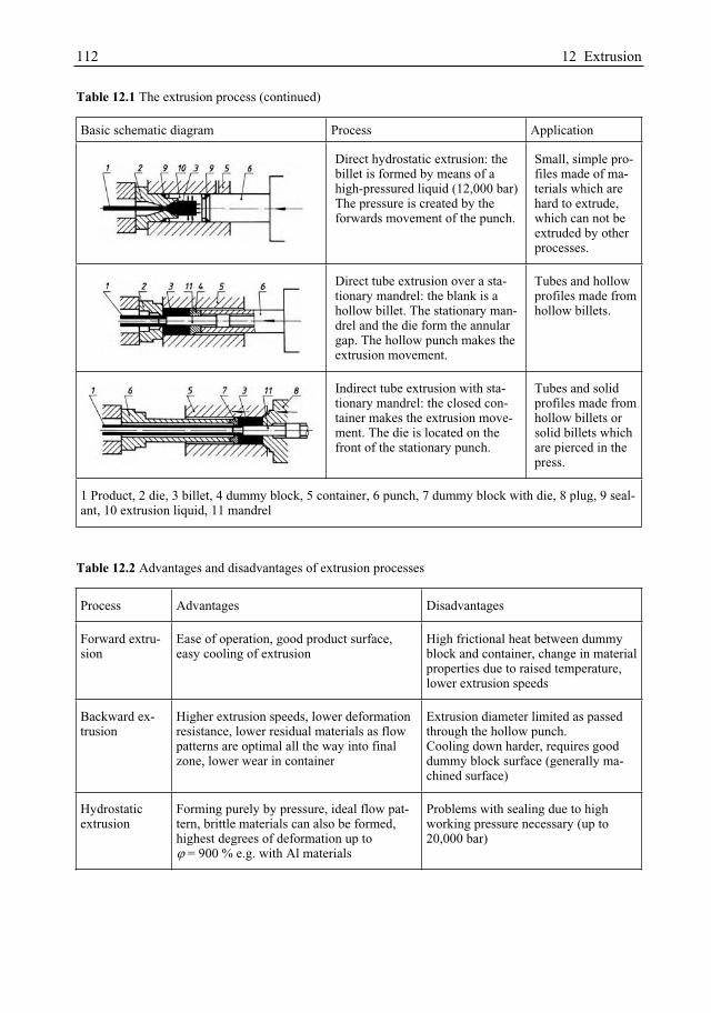
112 12 Extrusion
Table 12.1 The extrusion process (continued)
Basic schematic diagram Process Application
Direct hydrostatic extrusion: the billet is formed by means of a high-pressured liquid (12,000 bar) The pressure is created by the forwards movement of the punch.
Small, simple pro-files made of ma-terials which are hard to extrude, which can not be extruded by other processes.
Direct tube extrusion over a sta-tionary mandrel: the blank is a hollow billet. The stationary man-drel and the die form the annular gap. The hollow punch makes the extrusion movement.
Tubes and hollow profiles made from hollow billets.
Indirect tube extrusion with sta-tionary mandrel: the closed con-tainer makes the extrusion move-ment. The die is located on the front of the stationary punch.
Tubes and solid profiles made from hollow billets or solid billets which are pierced in the press.
1 Product, 2 die, 3 billet, 4 dummy block, 5 container, 6 punch, 7 dummy block with die, 8 plug, 9 seal-ant, 10 extrusion liquid, 11 mandrel
Table 12.2 Advantages and disadvantages of extrusion processes
Process Advantages Disadvantages
Forward extru-sion
Ease of operation, good product surface, easy cooling of extrusion
High frictional heat between dummy block and container, change in material properties due to raised temperature, lower extrusion speeds
Backward ex-trusion
Higher extrusion speeds, lower deformation resistance, lower residual materials as flow patterns are optimal all the way into final zone, lower wear in container
Extrusion diameter limited as passed through the hollow punch.Cooling down harder, requires good dummy block surface (generally ma-chined surface)
Hydrostatic extrusion
Forming purely by pressure, ideal flow pat-tern, brittle materials can also be formed, highest degrees of deformation up to
= 900 % e.g. with Al materials
Problems with sealing due to high working pressure necessary (up to 20,000 bar)
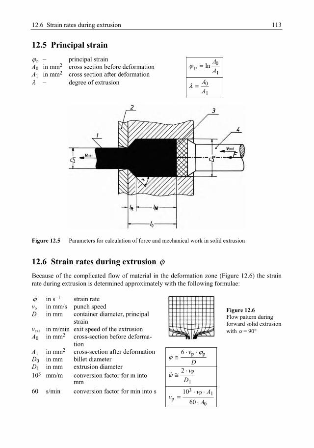
12.6 Strain rates during extrusion 113
12.5 Principal strain
p – principal strain A0 in mm2 cross section before deformation A1 in mm2 cross section after deformation
– degree of extrusion
0p
1
0
1
ln AA
AA
Figure 12.5 Parameters for calculation of force and mechanical work in solid extrusion
12.6 Strain rates during extrusion Because of the complicated flow of material in the deformation zone (Figure 12.6) the strain rate during extrusion is determined approximately with the following formulae:
in s–1 strain rate vp in mm/s punch speed D in mm container diameter, principal
strainvext in m/min exit speed of the extrusion A0 in mm2 cross-section before deforma-
tion A1 in mm2 cross-section after deformationD0 in mm billet diameter D1 in mm extrusion diameter 103 mm/m conversion factor for m into
mm60 s/min conversion factor for min into s
p p
p
13 p 1
p0
6
2
1060
vD
vD
v Av
A
Figure 12.6 Flow pattern during forward solid extrusion with = 90°
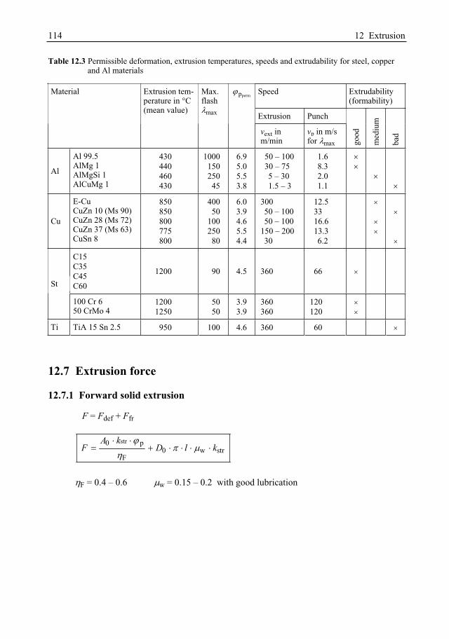
114 12 Extrusion
Table 12.3 Permissible deformation, extrusion temperatures, speeds and extrudability for steel, copper and Al materials
Speed Extrudability (formability)
Extrusion Punch
Material Extrusion tem-perature in °C (mean value)
Max.flash
max
pperm.
vext inm/min
vp in m/s for max go
od
med
ium
bad
Al
Al 99.5 AlMg 1 AlMgSi 1 AlCuMg 1
430440460430
100015025045
6.95.05.53.8
50 – 100 30 – 75 5 – 30 1.5 – 3
1.68.32.01.1
Cu
E-CuCuZn 10 (Ms 90) CuZn 28 (Ms 72) CuZn 37 (Ms 63) CuSn 8
850850800775800
40050
10025080
6.03.94.65.54.4
30050 – 100 50 – 100
150 – 200 30
12.53316.613.36.2
C15C35C45C60
1200 90 4.5 360 66St
100 Cr 6 50 CrMo 4
12001250
5050
3.93.9
360360
120120
Ti TiA 15 Sn 2.5 950 100 4.6 360 60
12.7 Extrusion force
12.7.1 Forward solid extrusion
F = Fdef + Ffr
str0 p0 w str
F
A kF D l k
F = 0.4 – 0.6 w = 0.15 – 0.2 with good lubrication

12.7 Extrusion force 115
12.7.2 Backward solid extrusion Here, the frictional force in the container does not apply as the billet does not move in the con-tainer.
0 str p
F
A kF
F in N total extrusion force Fdef in N deformation force Ffr in N frictional force in the container A0 in mm2 billet cross-sectional area D0 in mm billet diameter
p – principal strain F – deformation efficiency W – coefficient of friction for the wall friction in
the container kstr in N/mm2 yield strength
In hot forming, the yield strength, kstr, depends upon: the deformation temperature the strain rate.
The kstr values for the optimum deformation temperatures can be taken from Table 12.4 for a strain rate of = 1 s–1.The kstr value when the actual strain rate is taken into consideration can be calculated using the following equation:
1
m
str str1
.k k
As 1 = 1 is given the value s–1 (basic value in Table 12.4) the equation can be simplified:
1mstr strk k
kstr in N/mm2 yield strength with optimum deformation temperature and the actual strain rate
in s–1 actual strain rate st p6 vD
1 in s–1 basic speed 1 = 1 s–1
kstr1in N/mm2 yield strength with optimum deformation temperature and basic speed 1 = 1 s–1
m – material exponent kstr1and m can be taken from Table 12.4.
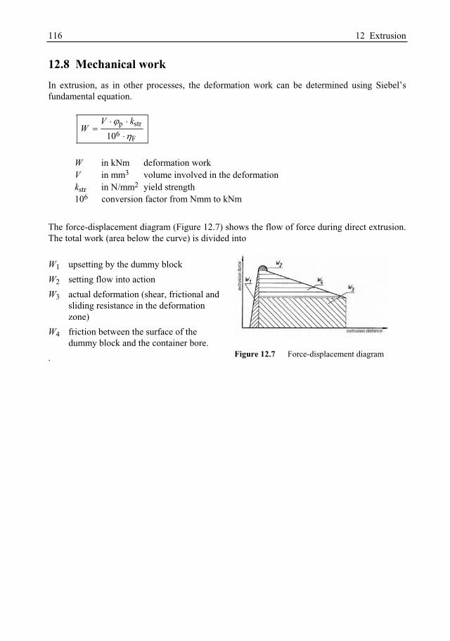
116 12 Extrusion
12.8 Mechanical work In extrusion, as in other processes, the deformation work can be determined using Siebel’s fundamental equation.
p str6 F10
V kW
W in kNm deformation work V in mm3 volume involved in the deformation kstr in N/mm2 yield strength 106 conversion factor from Nmm to kNm
The force-displacement diagram (Figure 12.7) shows the flow of force during direct extrusion. The total work (area below the curve) is divided into
W1 upsetting by the dummy block W2 setting flow into action W3 actual deformation (shear, frictional and
sliding resistance in the deformation zone)
W4 friction between the surface of the dummy block and the container bore.
. Figure 12.7 Force-displacement diagram
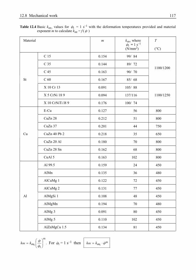
12.8 Mechanical work 117
Table 12.4 Basic kstr1 values for 1 = 1 s–1 with the deformation temperatures provided and material exponent m to calculate kstr = f ( )
Material m kstr1 where 1 = 1 s–1
(N/mm2)
T
(°C)
C 15 0.154 99/ 84
C 35 0.144 89/ 72
C 45 0.163 90/ 70
C 60 0.167 85/ 68
1100/1200
X 10 Cr 13 0.091 105/ 88
X 5 CrNi 18 9 0.094 137/116
St
X 10 CrNiTi l8 9 0.176 100/ 74
1100/1250
E-Cu 0.127 56 800
CuZn 28 0.212 51 800
CuZn 37 0.201 44 750
CuZn 40 Pb 2 0.218 35 650
CuZn 20 Al 0.180 70 800
CuZn 28 Sn 0.162 68 800
Cu
CuAl 5 0.163 102 800
Al 99.5 0.159 24 450
AlMn 0.135 36 480
AlCuMg 1 0.122 72 450
AlCuMg 2 0.131 77 450
AlMgSi 1 0.108 48 450
AlMgMn 0.194 70 480
AlMg 3 0.091 80 450
AlMg 5 0.110 102 450
Al
AlZnMgCu 1.5 0.134 81 450
1
m
str str1
.k k For 1 = 1 s–1 then 1mstr strk k
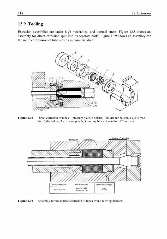
118 12 Extrusion
12.9 Tooling Extrusion assemblies are under high mechanical and thermal stress. Figure 12.8 shows an assembly for direct extrusion split into its separate parts; Figure 12.9 shows an assembly for the indirect extrusion of tubes over a moving mandrel.
Figure 12.8 Direct extrusion of tubes. 1 pressure plate, 2 bolster, 3 holder for bolster, 4 die, 5 man-drel, 6 die holder, 7 extrusion punch, 8 dummy block, 9 mandrel, 10 container
Figure 12.9 Assembly for the indirect extrusion of tubes over a moving mandrel
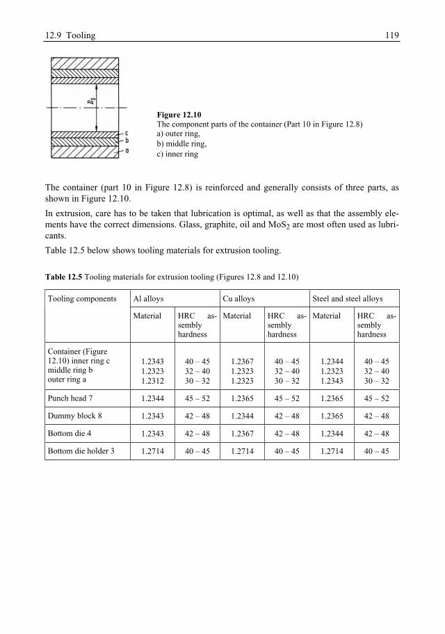
12.9 Tooling 119
Figure 12.10 The component parts of the container (Part 10 in Figure 12.8) a) outer ring,b) middle ring,c) inner ring
The container (part 10 in Figure 12.8) is reinforced and generally consists of three parts, as shown in Figure 12.10. In extrusion, care has to be taken that lubrication is optimal, as well as that the assembly ele-ments have the correct dimensions. Glass, graphite, oil and MoS2 are most often used as lubri-cants.Table 12.5 below shows tooling materials for extrusion tooling.
Table 12.5 Tooling materials for extrusion tooling (Figures 12.8 and 12.10)
Al alloys Cu alloys Steel and steel alloys Tooling components
Material HRC as-sembly hardness
Material HRC as-sembly hardness
Material HRC as-sembly hardness
Container (Figure 12.10) inner ring c middle ring b outer ring a
1.23431.23231.2312
40 – 45 32 – 40 30 – 32
1.23671.23231.2323
40 – 45 32 – 40 30 – 32
1.23441.23231.2343
40 – 45 32 – 40 30 – 32
Punch head 7 1.2344 45 – 52 1.2365 45 – 52 1.2365 45 – 52
Dummy block 8 1.2343 42 – 48 1.2344 42 – 48 1.2365 42 – 48
Bottom die 4 1.2343 42 – 48 1.2367 42 – 48 1.2344 42 – 48
Bottom die holder 3 1.2714 40 – 45 1.2714 40 – 45 1.2714 40 – 45
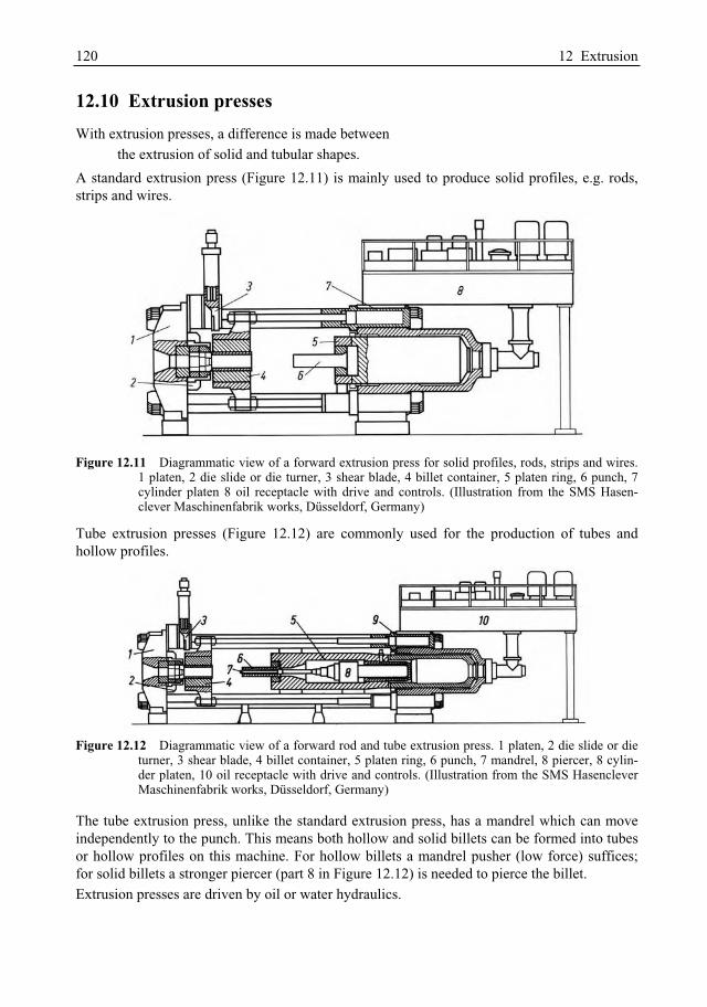
120 12 Extrusion
12.10 Extrusion presses With extrusion presses, a difference is made between the extrusion of solid and tubular shapes. A standard extrusion press (Figure 12.11) is mainly used to produce solid profiles, e.g. rods, strips and wires.
Figure 12.11 Diagrammatic view of a forward extrusion press for solid profiles, rods, strips and wires. 1 platen, 2 die slide or die turner, 3 shear blade, 4 billet container, 5 platen ring, 6 punch, 7 cylinder platen 8 oil receptacle with drive and controls. (Illustration from the SMS Hasen-clever Maschinenfabrik works, Düsseldorf, Germany)
Tube extrusion presses (Figure 12.12) are commonly used for the production of tubes and hollow profiles.
Figure 12.12 Diagrammatic view of a forward rod and tube extrusion press. 1 platen, 2 die slide or die turner, 3 shear blade, 4 billet container, 5 platen ring, 6 punch, 7 mandrel, 8 piercer, 8 cylin-der platen, 10 oil receptacle with drive and controls. (Illustration from the SMS Hasenclever Maschinenfabrik works, Düsseldorf, Germany)
The tube extrusion press, unlike the standard extrusion press, has a mandrel which can move independently to the punch. This means both hollow and solid billets can be formed into tubes or hollow profiles on this machine. For hollow billets a mandrel pusher (low force) suffices; for solid billets a stronger piercer (part 8 in Figure 12.12) is needed to pierce the billet. Extrusion presses are driven by oil or water hydraulics.
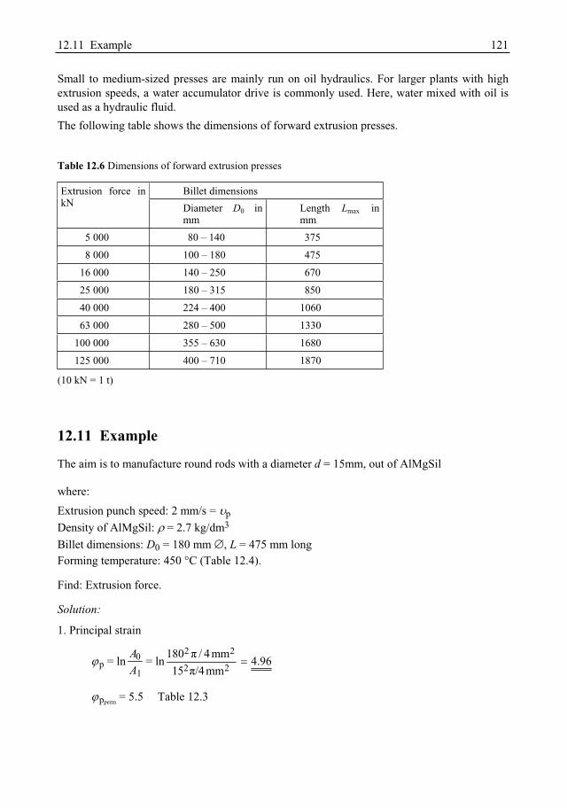
12.11 Example 121
Small to medium-sized presses are mainly run on oil hydraulics. For larger plants with high extrusion speeds, a water accumulator drive is commonly used. Here, water mixed with oil is used as a hydraulic fluid. The following table shows the dimensions of forward extrusion presses.
Table 12.6 Dimensions of forward extrusion presses
Billet dimensions Extrusion force in kN Diameter D0 in
mmLength Lmax in mm
5 000 80 – 140 375
8 000 100 – 180 475
16 000 140 – 250 670
25 000 180 – 315 850
40 000 224 – 400 1060
63 000 280 – 500 1330
100 000 355 – 630 1680
125 000 400 – 710 1870
(10 kN = 1 t)
12.11 Example
The aim is to manufacture round rods with a diameter d = 15mm, out of AlMgSil
where:Extrusion punch speed: 2 mm/s = pDensity of AlMgSil: = 2.7 kg/dm3
Billet dimensions: D0 = 180 mm , L = 475 mm long Forming temperature: 450 °C (Table 12.4).
Find: Extrusion force.
Solution:
1. Principal strain
p = ln 0
1
AA
= ln2 2
2 2180 / 4 mm 4.9615 /4mm
pperm = 5.5 Table 12.3

122 12 Extrusion
as p < pperm the extrusion dimensions can be produced in one extrusion operation.
2. Exit speed of the extrusion 2 2p 0
ext 3 3 2 21
ext
60 2mm 60s 1m 180 / 4mm10 s min 10 mm 15 / 4mm
17.28 m / min .
AA
3. Strain rate
p p0
6~ .D D
D
16 2mm 4.96 0.33s .s 180mm
4. Yield strength kstr
kstr1 = 48 N/mm2 for T = 450° C and = 1 s–1, Table 12.4
kstr = kstr1 · m , m = 0.108 from Table 12.4
kstr = 48 · 0.330.108 = 48 · 0.887 = 42.57 N/mm2 .
5. Extrusion force for solid forward extrusion
str p00 W str
F
A kF D l k
F = 0.5; W = 0.15 selected. 2 2
22
180 / 4mm 42.6 N 4.96 180mm 475mm 0.15 42.6 N / mm0.5 mm
10753655 N 1716393N 12470 kN .
F
12.12 Exercise on Chapter 12 1. What criteria are used to differentiate between the extrusion processes? 2. Name the most important extrusion processes and the typical fields of application. 3. What are the advantages and disadvantages of the extrusion process? 4. What values does kstr mainly depend upon? 5. How are extrusion presses categorised?
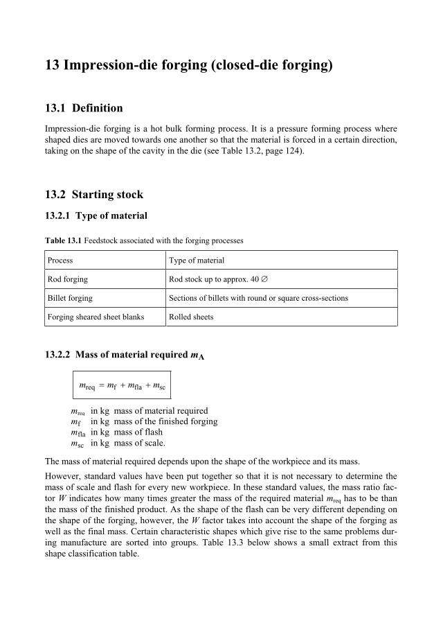
13 Impression-die forging (closed-die forging)
13.1 Definition Impression-die forging is a hot bulk forming process. It is a pressure forming process where shaped dies are moved towards one another so that the material is forced in a certain direction, taking on the shape of the cavity in the die (see Table 13.2, page 124).
13.2 Starting stock
13.2.1 Type of material
Table 13.1 Feedstock associated with the forging processes
Process Type of material
Rod forging Rod stock up to approx. 40
Billet forging Sections of billets with round or square cross-sections
Forging sheared sheet blanks Rolled sheets
13.2.2 Mass of material required mA
req f fla scm m m m
mreq in kg mass of material required mf in kg mass of the finished forging mfla in kg mass of flash msc in kg mass of scale.
The mass of material required depends upon the shape of the workpiece and its mass. However, standard values have been put together so that it is not necessary to determine the mass of scale and flash for every new workpiece. In these standard values, the mass ratio fac-tor W indicates how many times greater the mass of the required material mreq has to be than the mass of the finished product. As the shape of the flash can be very different depending on the shape of the forging, however, the W factor takes into account the shape of the forging as well as the final mass. Certain characteristic shapes which give rise to the same problems dur-ing manufacture are sorted into groups. Table 13.3 below shows a small extract from this shape classification table.

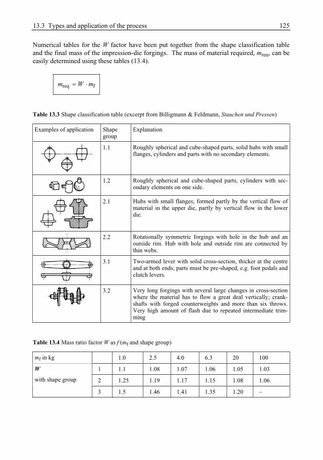
125
Numerical tables for the W factor have been put together from the shape classification table and the final mass of the impression-die forgings. The mass of material required, mreq, can be easily determined using these tables (13.4).
req fm W m
Table 13.3 Shape classification table (excerpt from Billigmann & Feldmann, Stauchen und Pressen)
Examples of application Shape group
Explanation
1.1 Roughly spherical and cube-shaped parts, solid hubs with small flanges, cylinders and parts with no secondary elements.
1.2 Roughly spherical and cube-shaped parts, cylinders with sec-ondary elements on one side.
2.1 Hubs with small flanges; formed partly by the vertical flow of material in the upper die, partly by vertical flow in the lower die.
2.2 Rotationally symmetric forgings with hole in the hub and an outside rim. Hub with hole and outside rim are connected by thin webs.
3.1 Two-armed lever with solid cross-section, thicker at the centre and at both ends; parts must be pre-shaped, e.g. foot pedals and clutch levers.
3.2 Very long forgings with several large changes in cross-section where the material has to flow a great deal vertically; crank-shafts with forged counterweights and more than six throws. Very high amount of flash due to repeated intermediate trim-ming
Table 13.4 Mass ratio factor W as f (mf and shape group)
mf in kg 1.0 2.5 4.0 6.3 20 100
1 1.1 1.08 1.07 1.06 1.05 1.03
2 1.25 1.19 1.17 1.15 1.08 1.06
W
with shape group
3 1.5 1.46 1.41 1.35 1.20 –
13.3 Types and application of the process
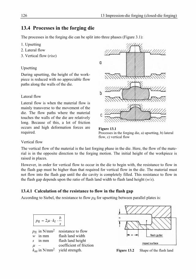
126 13 Impression-die forging (closed-die forging)
13.4 Processes in the forging die The processes in the forging die can be split into three phases (Figure 3.1):
1. Upsetting 2. Lateral flow 3. Vertical flow (rise)
Upsetting During upsetting, the height of the work-piece is reduced with no appreciable flow paths along the walls of the die.
Lateral flow Lateral flow is when the material flow is mainly transverse to the movement of the die. The flow paths where the material touches the walls of the die are relatively long. Because of this, a lot of friction occurs and high deformation forces are required.
Figure 13.1 Processes in the forging die, a) upsetting, b) lateral flow, c) vertical flow
Vertical flow The vertical flow of the material is the last forging phase in the die. Here, the flow of the mate-rial is in the opposite direction to the forging motion. The initial height of the workpiece is raised in places. However, in order for vertical flow to occur in the die to begin with, the resistance to flow in the flash gap must be higher than that required for vertical flow in the die. The material must not flow into the flash gap until the die cavity is completely filled. This resistance to flow in the flash gap depends upon the ratio of flash land width to flash land height (w/s).
13.4.1 Calculation of the resistance to flow in the flash gap According to Siebel, the resistance to flow pfl for upsetting between parallel plates is:
fl f2 bp ks
pfl in N/mm2 resistance to flow w in mm flash land width s in mm flash land height
– coefficient of friction kstr in N/mm2 yield strength. Figure 13.2 Shape of the flash land
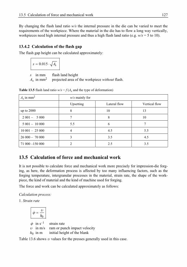
13.5 Calculation of force and mechanical work 127
By changing the flash land ratio w/s the internal pressure in the die can be varied to meet the requirements of the workpiece. Where the material in the die has to flow a long way vertically, workpieces need high internal pressure and thus a high flash land ratio (e.g. w/s = 5 to 10).
13.4.2 Calculation of the flash gap The flash gap height can be calculated approximately:
s0.015s A
s in mm flash land height As in mm2 projected area of the workpiece without flash.
Table 13.5 flash land ratio w/s = f (As and the type of deformation)
As in mm2 w/s mainly for
Upsetting Lateral flow Vertical flow
up to 2000 8 10 13
2 001 – 5 000 7 8 10
5 001 – 10 000 5.5 6 7
10 001 – 25 000 4 4.5 5.5
26 000 – 70 000 3 3.5 4.5
71 000 –150 000 2 2.5 3.5
13.5 Calculation of force and mechanical work It is not possible to calculate force and mechanical work more precisely for impression-die forg-ing, as here, the deformation process is affected by too many influencing factors, such as the forging temperature, intergranular processes in the material, strain rate, the shape of the work-piece, the kind of material and the kind of machine used for forging. The force and work can be calculated approximately as follows:
Calculation process:1. Strain rate
0h
in s–1 strain rate in m/s ram or punch impact velocity
h0 in m initial height of the blank Table 13.6 shows values for the presses generally used in this case.

128 13 Impression-die forging (closed-die forging)
Tab
le 1
3.6
Stra
in ra
te
= f
(r a
nd in
itial
hei
ght h
0of
the
blan
k)

13.5 Calculation of force and mechanical work 129
2. Yield strength
1mstr strk k
m – material exponent kstr in N/mm2 yield strength for the strain rate and the forging temperature Tkstr1 in N/mm2 yield strength for = 1 (s–1) at forging temperature T (kstr1 from Table
12.4, page 117) in s–1 strain rate (for from 1 to 300 s–1, kstr can also be taken from Table
13.7)
3. Yield strength at the end of forging
re strk y k
kre in N/mm2 yield strength at the end of forging Take shape factor y (takes the shape of the workpiece into account) from Table 13.8.
4. Maximum forging force
d reF A k
F in N max. forging force Ad in mm2 projected area of the forging including flash land.
5. Mean principal strainAs the height h1 of the forging can not be precisely defined, here the mean final height h1m is worked with, determined from the volume and the projected area of the forging (Figure 13.3).
1p
0ln ,h
h m1d
VhA
mpd 0
ln VA h
Figure 13.3 Definition of the mean final height
h1 in mm height after forging h0 in mm blank height V in mm3 volume of the forging
pm – mean principal strain
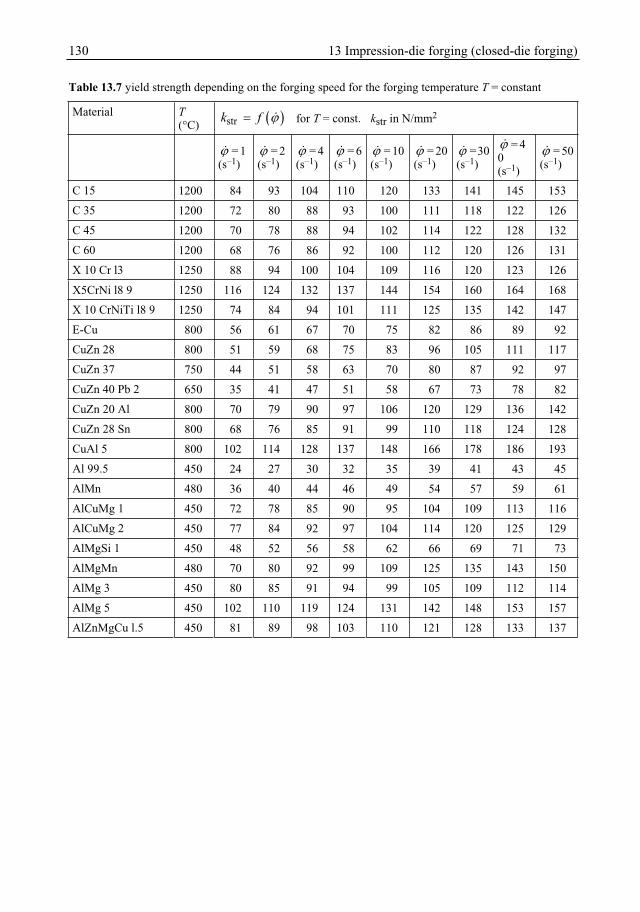
130 13 Impression-die forging (closed-die forging)
Table 13.7 yield strength depending on the forging speed for the forging temperature T = constant
Material T(°C) strk f for T = const. kstr in N/mm2
= 1 (s–1)
= 2(s–1)
= 4(s–1)
= 6(s–1)
= 10(s–1)
= 20(s–1)
=30 (s–1)
= 40(s–1)
= 50 (s–1)
C 15 1200 84 93 104 110 120 133 141 145 153
C 35 1200 72 80 88 93 100 111 118 122 126
C 45 1200 70 78 88 94 102 114 122 128 132
C 60 1200 68 76 86 92 100 112 120 126 131
X 10 Cr l3 1250 88 94 100 104 109 116 120 123 126
X5CrNi l8 9 1250 116 124 132 137 144 154 160 164 168
X 10 CrNiTi l8 9 1250 74 84 94 101 111 125 135 142 147
E-Cu 800 56 61 67 70 75 82 86 89 92
CuZn 28 800 51 59 68 75 83 96 105 111 117
CuZn 37 750 44 51 58 63 70 80 87 92 97
CuZn 40 Pb 2 650 35 41 47 51 58 67 73 78 82
CuZn 20 Al 800 70 79 90 97 106 120 129 136 142
CuZn 28 Sn 800 68 76 85 91 99 110 118 124 128
CuAl 5 800 102 114 128 137 148 166 178 186 193
Al 99.5 450 24 27 30 32 35 39 41 43 45
AlMn 480 36 40 44 46 49 54 57 59 61
AlCuMg 1 450 72 78 85 90 95 104 109 113 116
AlCuMg 2 450 77 84 92 97 104 114 120 125 129
AlMgSi 1 450 48 52 56 58 62 66 69 71 73
AlMgMn 480 70 80 92 99 109 125 135 143 150
AlMg 3 450 80 85 91 94 99 105 109 112 114
AlMg 5 450 102 110 119 124 131 142 148 153 157
AlZnMgCu l.5 450 81 89 98 103 110 121 128 133 137

13.5 Calculation of force and mechanical work 131
=70 (s–1)
=100 (s–1)
=150 (s–1)
=200 (s–1)
=250(s–1)
=300(s–1)
161 170 181 189 196 201
133 140 148 154 159 164
140 148 158 166 172 177
138 147 157 164 171 176
130 134 139 143 145 148
173 179 186 191 195 198
156 166 179 188 196 202
96 101 106 110 113 116
126 135 148 157 164 171
103 111 120 128 133 138
88 96 104 111 117 121
150 160 172 182 189 195
135 143 153 160 166 171
204 216 231 242 251 258
47 50 53 56 58 59
64 67 71 74 76 78
121 126 133 137 141 144
134 141 148 154 159 163
76 79 82 85 87 89
160 171 185 196 204 212
118 122 126 130 132 134
163 169 177 183 187 191
143 150 159 165 170 174
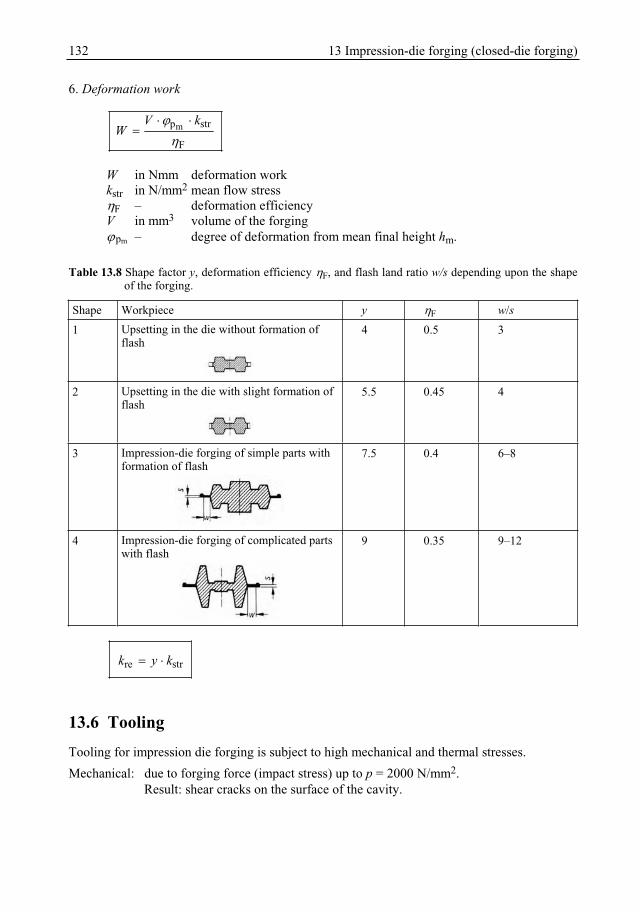
132 13 Impression-die forging (closed-die forging)
6. Deformation work
mp str
F
V kW
W in Nmm deformation work kstr in N/mm2 mean flow stress
F – deformation efficiency V in mm3 volume of the forging
pm – degree of deformation from mean final height hm.
Table 13.8 Shape factor y, deformation efficiency F, and flash land ratio w/s depending upon the shape of the forging.
Shape Workpiece y F w/s1 Upsetting in the die without formation of
flash4 0.5 3
2 Upsetting in the die with slight formation of flash
5.5 0.45 4
3 Impression-die forging of simple parts with formation of flash
7.5 0.4 6–8
4 Impression-die forging of complicated parts with flash
9 0.35 9–12
re strk y k
13.6 Tooling Tooling for impression die forging is subject to high mechanical and thermal stresses. Mechanical: due to forging force (impact stress) up to p = 2000 N/mm2.
Result: shear cracks on the surface of the cavity.
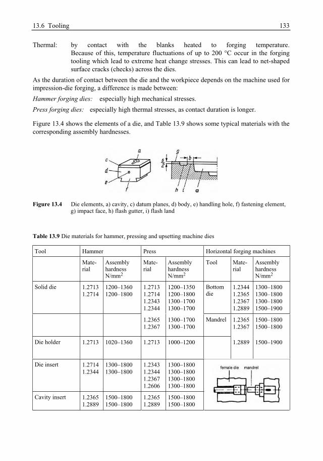
13.6 Tooling 133
Thermal: by contact with the blanks heated to forging temperature. Because of this, temperature fluctuations of up to 200 °C occur in the forging tooling which lead to extreme heat change stresses. This can lead to net-shaped surface cracks (checks) across the dies.
As the duration of contact between the die and the workpiece depends on the machine used for impression-die forging, a difference is made between: Hammer forging dies: especially high mechanical stresses. Press forging dies: especially high thermal stresses, as contact duration is longer.
Figure 13.4 shows the elements of a die, and Table 13.9 shows some typical materials with the corresponding assembly hardnesses.
Figure 13.4 Die elements, a) cavity, c) datum planes, d) body, e) handling hole, f) fastening element, g) impact face, h) flash gutter, i) flash land
Table 13.9 Die materials for hammer, pressing and upsetting machine dies
Tool Hammer Press Horizontal forging machines
Mate-rial
Assembly hardnessN/mm2
Mate-rial
Assembly hardnessN/mm2
Tool Mate-rial
Assembly hardnessN/mm2
Solid die 1.27131.2714
1200–13601200–1800
1.27131.27141.23431.2344
1200–13501200–18001300–17001300–1700
Bottom die
1.23441.23651.23671.2889
1300–18001300–18001300–18001500–1900
1.23651.2367
1300–17001300–1700
Mandrel 1.23651.2367
1500–18001500–1800
Die holder 1.2713 1020–1360 1.2713 1000–1200 1.2889 1500–1900
Die insert 1.27141.2344
1300–18001300–1800
1.23431.23441.23671.2606
1300–18001300–18001300–18001300–1800
Cavity insert 1.23651.2889
1500–18001500–1800
1.23651.2889
1500–18001500–1800
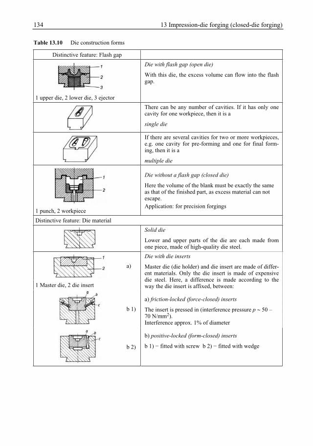
134 13 Impression-die forging (closed-die forging)
Table 13.10 Die construction forms
Distinctive feature: Flash gap
1 upper die, 2 lower die, 3 ejector
Die with flash gap (open die)
With this die, the excess volume can flow into the flash gap.
There can be any number of cavities. If it has only one cavity for one workpiece, then it is a
single die
If there are several cavities for two or more workpieces, e.g. one cavity for pre-forming and one for final form-ing, then it is a
multiple die
1 punch, 2 workpiece
Die without a flash gap (closed die)
Here the volume of the blank must be exactly the same as that of the finished part, as excess material can not escape. Application: for precision forgings
Distinctive feature: Die material Solid die
Lower and upper parts of the die are each made from one piece, made of high-quality die steel.
a)
1 Master die, 2 die insert
b 1)
b 2)
Die with die inserts
Master die (die holder) and die insert are made of differ-ent materials. Only the die insert is made of expensive die steel. Here, a difference is made according to the way the die insert is affixed, between:
a) friction-locked (force-closed) inserts
The insert is pressed in (interference pressure p 50 – 70 N/mm2).Interference approx. 1% of diameter
b) positive-locked (form-closed) inserts
b 1) fitted with screw b 2) fitted with wedge
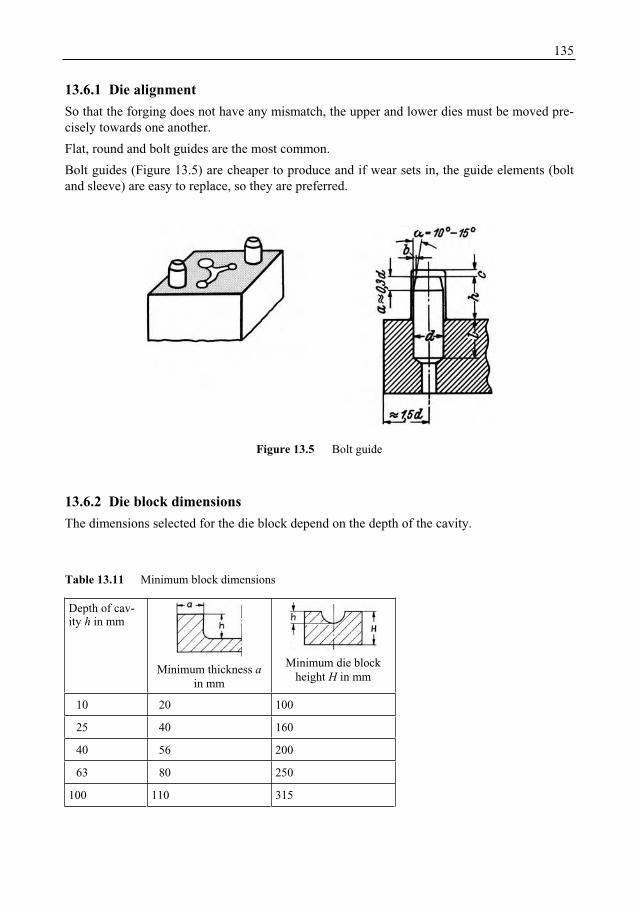
135
13.6.1 Die alignment So that the forging does not have any mismatch, the upper and lower dies must be moved pre-cisely towards one another. Flat, round and bolt guides are the most common. Bolt guides (Figure 13.5) are cheaper to produce and if wear sets in, the guide elements (bolt and sleeve) are easy to replace, so they are preferred.
Figure 13.5 Bolt guide
13.6.2 Die block dimensions The dimensions selected for the die block depend on the depth of the cavity.
Table 13.11 Minimum block dimensions
Depth of cav-ity h in mm
Minimum thickness ain mm
Minimum die block height H in mm
10 20 100
25 40 160
40 56 200
63 80 250
100 110 315
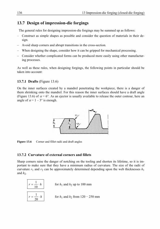
136 13 Impression-die forging (closed-die forging)
13.7 Design of impression-die forgings The general rules for designing impression-die forgings may be summed up as follows: – Construct as simple shapes as possible and consider the question of materials in their de-
sign. – Avoid sharp corners and abrupt transitions in the cross-section. – When designing the shape, consider how it can be gripped for mechanical processing. – Consider whether complicated forms can be produced more easily using other manufactur-
ing processes.
As well as these rules, when designing forgings, the following points in particular should be taken into account:
13.7.1 Drafts (Figure 13.6)
On the inner surfaces created by a mandrel penetrating the workpiece, there is a danger of them shrinking onto the mandrel. For this reason the inner surfaces should have a draft angle (Figure 13.6) of = 6°. As an ejector is usually available to release the outer contour, here an angle of = 1 – 3° is enough.
Figure 13.6 Corner and fillet radii and draft angles
13.7.2 Curvature of external corners and fillets
Sharp corners raise the danger of notching on the tooling and shorten its lifetime, so it is im-portant to make sure that they have a minimum radius of curvature. The size of the radii of curvature r1 and r2 can be approximately determined depending upon the web thicknesses h1and h2.
110
r h for h1 and h2 up to 100 mm
120
r h for h1 and h2 from 120 250 mm
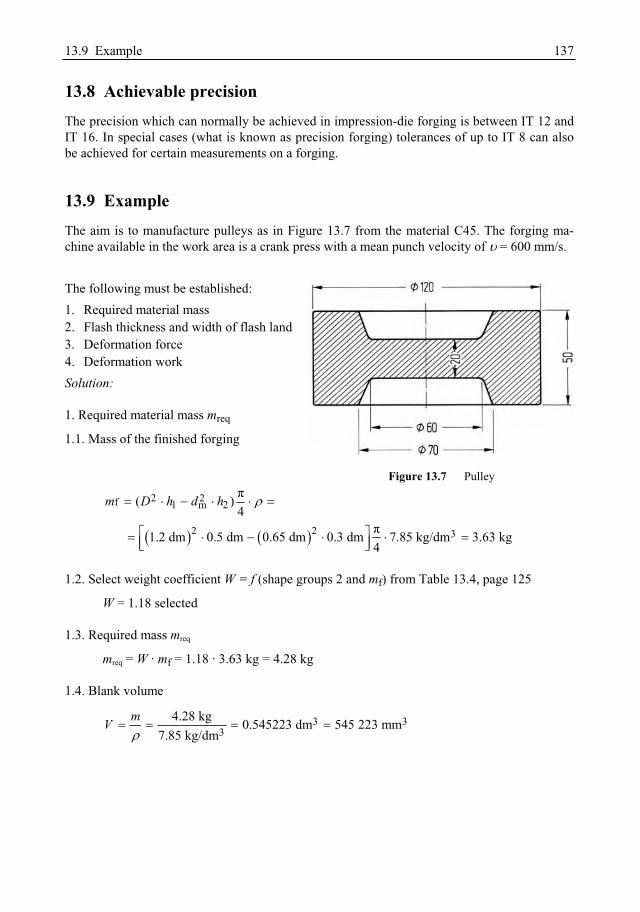
13.9 Example 137
13.8 Achievable precision The precision which can normally be achieved in impression-die forging is between IT 12 and IT 16. In special cases (what is known as precision forging) tolerances of up to IT 8 can also be achieved for certain measurements on a forging.
13.9 Example The aim is to manufacture pulleys as in Figure 13.7 from the material C45. The forging ma-chine available in the work area is a crank press with a mean punch velocity of = 600 mm/s.
The following must be established: 1. Required material mass 2. Flash thickness and width of flash land 3. Deformation force 4. Deformation work Solution:
1. Required material mass mreq
1.1. Mass of the finished forging
Figure 13.7 Pulley
2 2f 1 m 2( )4
m D h d h
2 2 31.2 dm 0.5 dm 0.65 dm 0.3 dm 7.85 kg/dm 3.63 kg4
1.2. Select weight coefficient W = f (shape groups 2 and mf) from Table 13.4, page 125
W = 1.18 selected
1.3. Required mass mreq
mreq = W · mf = 1.18 · 3.63 kg = 4.28 kg
1.4. Blank volume
3 33
4.28 kg 0.545223 dm 545 223 mm7.85 kg/dm
mV

138 13 Impression-die forging (closed-die forging)
1.5. Blank dimensions initial diameter D0 = 110 mm selected
30 20
545223 mm 57.40 mm(110 mm)
4
VhA
h0 = 60 mm selected
2. Flash height s2 2s 120 /4 11 309 mmA
s = 0.015 0.015 11 309 1.59 mms As = 1.6 mm selected.
The workpiece corresponds to shape 2 (Table 13.8, upset part with slight formation of flash), so a flash land ratio of w/s = 4 is assumed (Table 13.5). From this it follows that:
w = 4 · s = 4 · 1.6 mm = 6.4 mm w = 6.0 mm selected.
From the flash land width and the diameter of the finished part, the projected diameter Dd and the projected area of the forging including flash land Ad can now be determined.
Projected diameter:
Dd = D + 2 · w = 120 mm + 2 · 6 mm = 132 mm
Projected area Ad:
22 2d d
(132 mm) 13 678 mm4 4
A D
3. Deformation force and deformation work 3.1.Strain rate
10
600 mm/s 10 s60 mm
vh
3.2. Yield strength
kstr = kstr1 · m = 70 N/mm2 · 100.163 = 102 N/mm2
from Table 12.4:
m = 0.163 kstr1 = 70 N/mm2 for T = 1200 °C
or from Table 13.7 the kstr value for = 10 s–1.

13.10 Exercise on Chapter 13 139
3.3. Deformation resistance at the end of deformation
kre = y · kstr = 5.5 · 102 N/mm2 = 561 N/mm2 y = 5.5 from Table 13.8 – Shape 2
3.4. Deformation force
F = Ad · kre = 13678 mm2 · 561 N/mm2 = 7673 358 N = 7673 kN
3.5. Mean principal strain
m
2 2fp 2d 0
110 mm 60 mmln ln 0.3644 13 678 mm 60 mm
VA h
Vf in mm3 volume employed with h0 = 60 mm
3.6. Deformation work
m3 2f p str
6F
570 199 mm 0.364 102 N/mm 52.9 kNm0.45 10
V kW
F = 0.45 from Table 13.8 106 – conversion factor in kNm
13.10 Exercise on Chapter 13
1. What are the different impression-die forging processes? 2. What auxiliary factor can be used to determine the required masses to be used? 3. What is the significance of the flash land on the forging die and what can it be used to con-
trol? 4. What values does the yield strength depend upon during impression-die forging? 5. As a result, what must be considered for the application of the machines? 6. Which criteria are used to differentiate between the construction forms of the forging dies? 7. Name the three phases which take place in the die during impression-die forging. 8. What factors concerning the die can be used to influence the resistance to flow in the flash
gap? 9. Which machines are most commonly used for impression-die forging?

140 13 Impression-die forging (closed-die forging)
Table 13.12 kstr1 = f (T ) for = 1 s–1 (12.4)
Material m kstr1 where = 1 s–1
(N/mm2)T (°C)
C 15 0,154 99/ 84
C 35 0,144 89/ 72
C 45 0,163 90/ 70
C 60 0,167 85/ 68
1100/1200
X 10 Cr l3 0,091 105/ 88
X 5 CrNi l8 9 0,094 137/116
St
X 10 CrNiTi 18 9 0,176 100/ 74
1100/1250
E-Cu 0,127 56 800
CuZn 28 0,212 51 800
CuZn 37 0,201 44 750
CuZn 40 Pb 2 0,218 35 650
CuZn 20 Al 0,180 70 800
CuZn 28 Sn 0,162 68 800
Cu
CuAl 5 0,163 102 800
Al 99.5 0,159 24 450
AlMn 0,135 36 480
AlCuMg 1 0,122 72 450
AlCuMg 2 0,131 77 450
AlMgSi 1 0,108 48 450
AlMgMn 0,194 70 480
AlMg 3 0,091 80 450
AlMg 5 0,110 102 450
Al
AlZnMgCu 1.5 0,134 81 450
1
m
str str1
k k For = 1 s–1 then 1mstr strk k
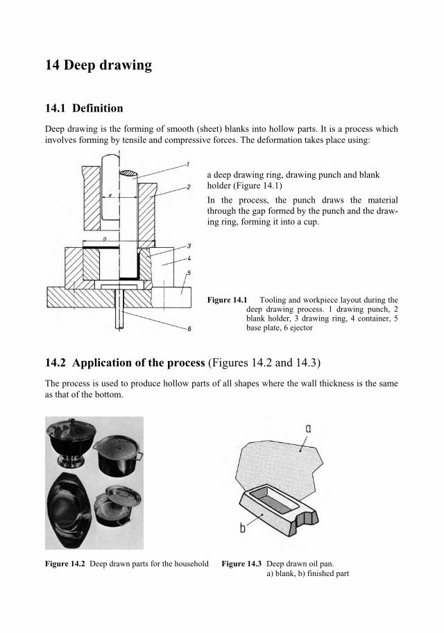
14 Deep drawing
14.1 Definition Deep drawing is the forming of smooth (sheet) blanks into hollow parts. It is a process which involves forming by tensile and compressive forces. The deformation takes place using:
a deep drawing ring, drawing punch and blank holder (Figure 14.1) In the process, the punch draws the material through the gap formed by the punch and the draw-ing ring, forming it into a cup.
Figure 14.1 Tooling and workpiece layout during the deep drawing process. 1 drawing punch, 2 blank holder, 3 drawing ring, 4 container, 5 base plate, 6 ejector
14.2 Application of the process (Figures 14.2 and 14.3)
The process is used to produce hollow parts of all shapes where the wall thickness is the same as that of the bottom.
Figure 14.2 Deep drawn parts for the household Figure 14.3 Deep drawn oil pan.a) blank, b) finished part
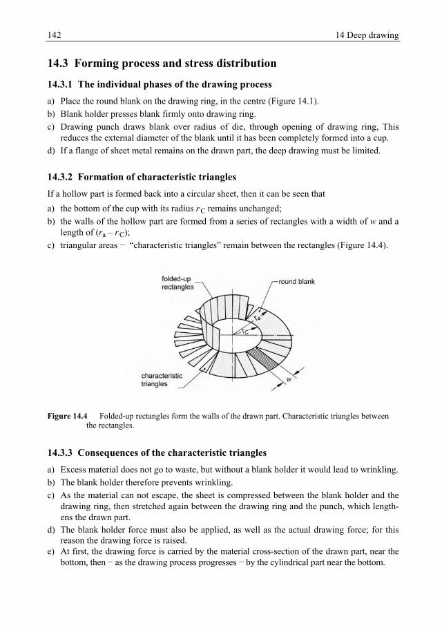
142 14 Deep drawing
14.3 Forming process and stress distribution
14.3.1 The individual phases of the drawing process a) Place the round blank on the drawing ring, in the centre (Figure 14.1). b) Blank holder presses blank firmly onto drawing ring. c) Drawing punch draws blank over radius of die, through opening of drawing ring, This
reduces the external diameter of the blank until it has been completely formed into a cup. d) If a flange of sheet metal remains on the drawn part, the deep drawing must be limited.
14.3.2 Formation of characteristic triangles If a hollow part is formed back into a circular sheet, then it can be seen that a) the bottom of the cup with its radius rC remains unchanged; b) the walls of the hollow part are formed from a series of rectangles with a width of w and a
length of (ra – rC);c) triangular areas “characteristic triangles” remain between the rectangles (Figure 14.4).
Figure 14.4 Folded-up rectangles form the walls of the drawn part. Characteristic triangles between the rectangles.
14.3.3 Consequences of the characteristic triangles a) Excess material does not go to waste, but without a blank holder it would lead to wrinkling. b) The blank holder therefore prevents wrinkling. c) As the material can not escape, the sheet is compressed between the blank holder and the
drawing ring, then stretched again between the drawing ring and the punch, which length-ens the drawn part.
d) The blank holder force must also be applied, as well as the actual drawing force; for this reason the drawing force is raised.
e) At first, the drawing force is carried by the material cross-section of the drawn part, near the bottom, then as the drawing process progresses by the cylindrical part near the bottom.
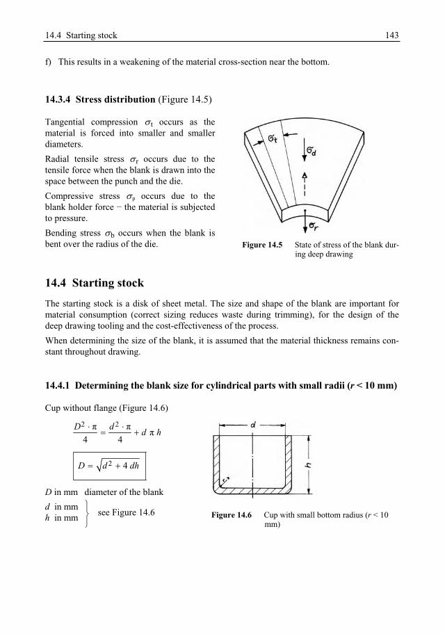
14.4 Starting stock 143
f) This results in a weakening of the material cross-section near the bottom.
14.3.4 Stress distribution (Figure 14.5)
Tangential compression t occurs as the material is forced into smaller and smaller diameters. Radial tensile stress r occurs due to the tensile force when the blank is drawn into the space between the punch and the die. Compressive stress p occurs due to the blank holder force the material is subjected to pressure. Bending stress b occurs when the blank is bent over the radius of the die. Figure 14.5 State of stress of the blank dur-
ing deep drawing
14.4 Starting stock The starting stock is a disk of sheet metal. The size and shape of the blank are important for material consumption (correct sizing reduces waste during trimming), for the design of the deep drawing tooling and the cost-effectiveness of the process. When determining the size of the blank, it is assumed that the material thickness remains con-stant throughout drawing.
14.4.1 Determining the blank size for cylindrical parts with small radii (r < 10 mm)
Cup without flange (Figure 14.6)
2 2
4 4D d d h
2 4D d dh
D in mm diameter of the blank d in mm h in mm see Figure 14.6 Figure 14.6 Cup with small bottom radius (r < 10
mm)
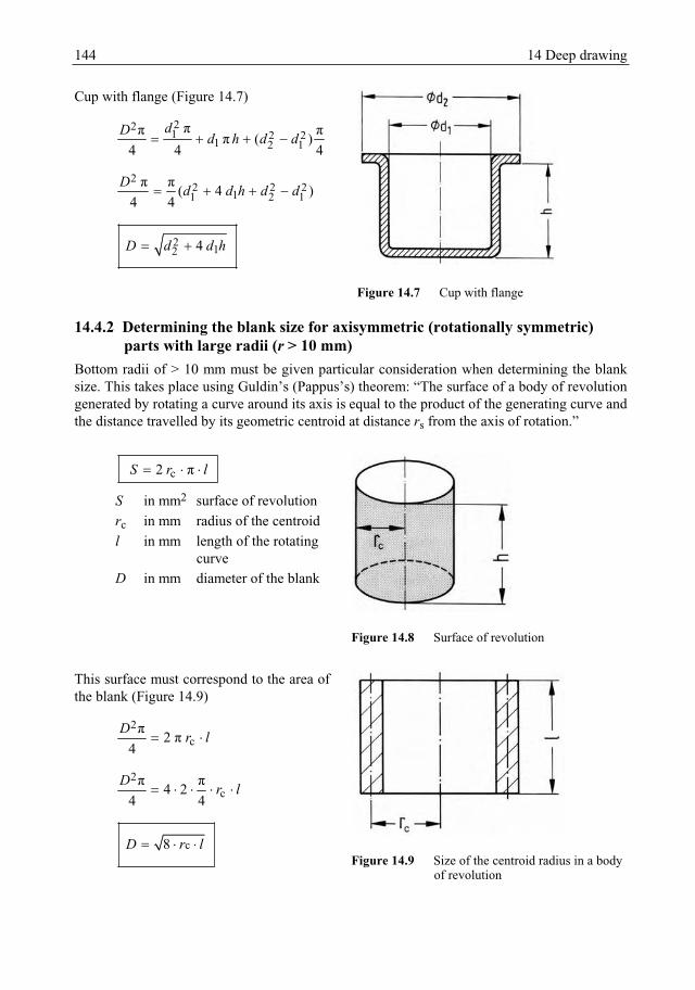
144 14 Deep drawing
Cup with flange (Figure 14.7)
221 2 21 2 1( )
4 4 4dD d h d d
22 2 211 2 1( 4 )
4 4D d d h d d
2 12 4D d d h
Figure 14.7 Cup with flange
14.4.2 Determining the blank size for axisymmetric (rotationally symmetric) parts with large radii (r > 10 mm)
Bottom radii of > 10 mm must be given particular consideration when determining the blank size. This takes place using Guldin’s (Pappus’s) theorem: “The surface of a body of revolution generated by rotating a curve around its axis is equal to the product of the generating curve and the distance travelled by its geometric centroid at distance rs from the axis of rotation.”
c2S r l
S in mm2 surface of revolution rc in mm radius of the centroid l in mm length of the rotating
curveD in mm diameter of the blank
Figure 14.8 Surface of revolution
This surface must correspond to the area of the blank (Figure 14.9)
2c2
4D r l
2c4 2
4 4D r l
c8D r lFigure 14.9 Size of the centroid radius in a body
of revolution
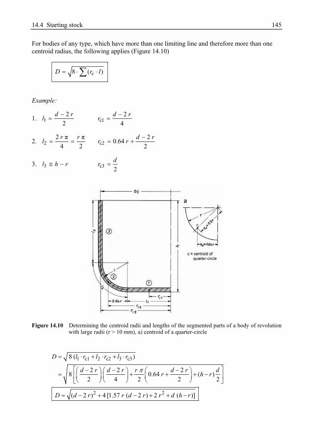
14.4 Starting stock 145
For bodies of any type, which have more than one limiting line and therefore more than one centroid radius, the following applies (Figure 14.10)
c8 ( )D r l
Example:
1. 12
2d rl c1
24
d rr
2. 22
4 2r rl c2
20.642
d rr r
3. 3l h r c3 2dr
Figure 14.10 Determining the centroid radii and lengths of the segmented parts of a body of revolution with large radii (r > 10 mm), a) centroid of a quarter-circle
1 c1 2 c2 3 c3
2 2
8 ( )
2 2 28 0.64 ( )2 4 2 2 2
( 2 ) 4 [1.57 ( 2 ) 2 ( )]
D l r l r l r
d r d r r d r dr h r
D d r r d r r d h r
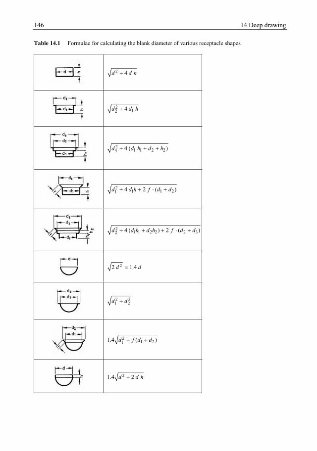
146 14 Deep drawing
Table 14.1 Formulae for calculating the blank diameter of various receptacle shapes
2 4d d h
212 4d d h
21 1 2 23 4 ( )d d h d h
21 1 21 4 2 ( )d d h f d d
21 1 2 2 2 32 4 ( ) 2 ( )d d h d h f d d
22 1.4d d
2 21 2d d
21 211.4 ( )d f d d
21.4 2d d h
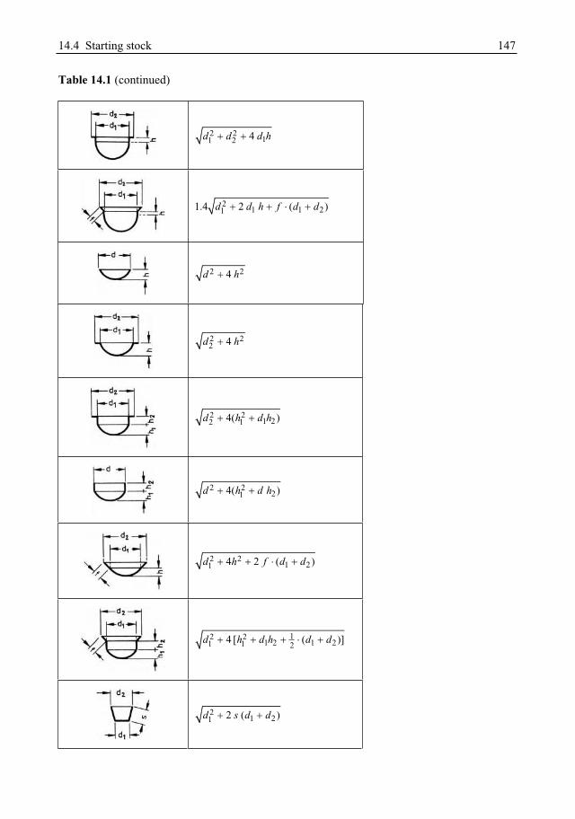
14.4 Starting stock 147
Table 14.1 (continued)
2 211 2 4d d d h
21 1 211.4 2 ( )d d h f d d
2 24d h
2 22 4d h
2 21 22 14( )d h d h
2 2214( )d h d h
2 21 21 4 2 ( )d h f d d
12 21 2 1 21 1 24 [ ( )]d h d h d d
21 21 2 ( )d s d d
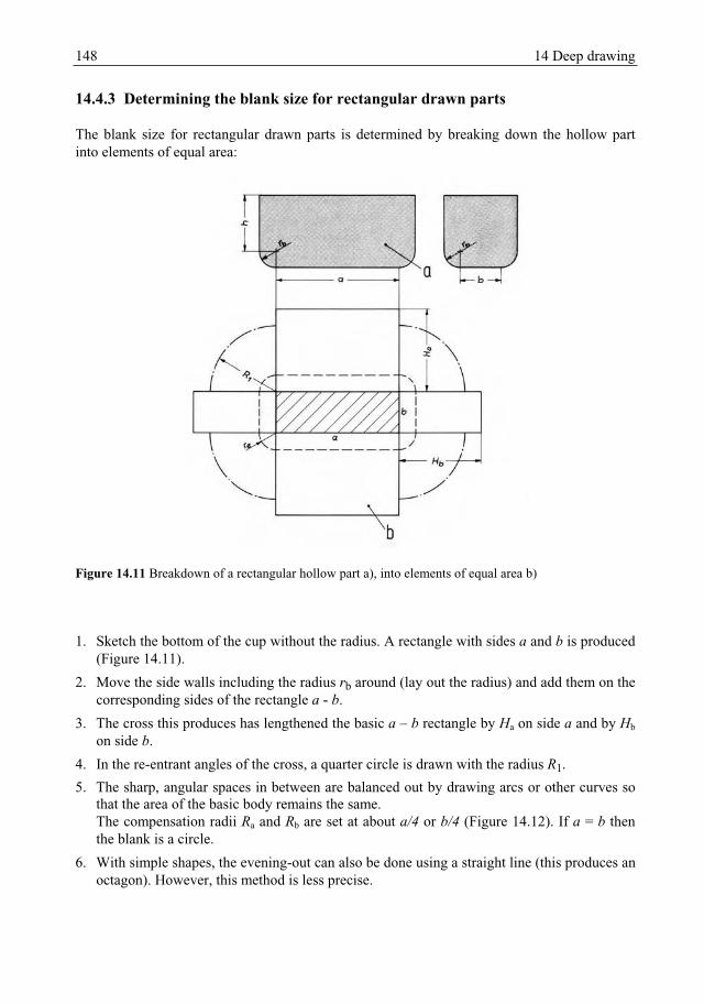
148 14 Deep drawing
14.4.3 Determining the blank size for rectangular drawn parts
The blank size for rectangular drawn parts is determined by breaking down the hollow part into elements of equal area:
Figure 14.11 Breakdown of a rectangular hollow part a), into elements of equal area b)
1. Sketch the bottom of the cup without the radius. A rectangle with sides a and b is produced (Figure 14.11).
2. Move the side walls including the radius rb around (lay out the radius) and add them on the corresponding sides of the rectangle a - b.
3. The cross this produces has lengthened the basic a – b rectangle by Ha on side a and by Hbon side b.
4. In the re-entrant angles of the cross, a quarter circle is drawn with the radius R1.5. The sharp, angular spaces in between are balanced out by drawing arcs or other curves so
that the area of the basic body remains the same. The compensation radii Ra and Rb are set at about a/4 or b/4 (Figure 14.12). If a = b then the blank is a circle.
6. With simple shapes, the evening-out can also be done using a straight line (this produces an octagon). However, this method is less precise.
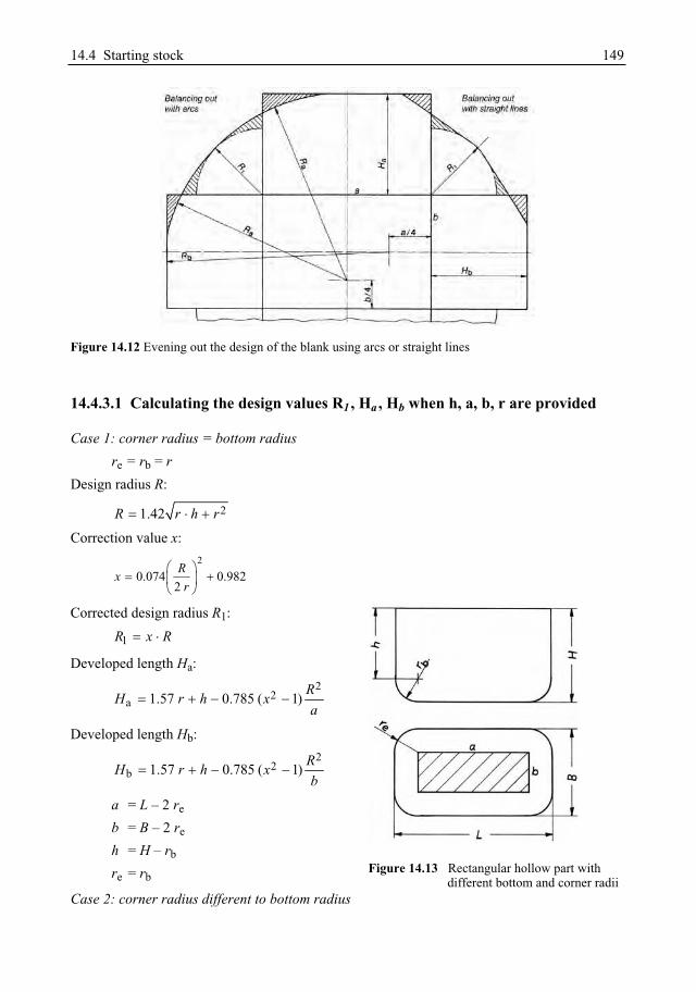
14.4 Starting stock 149
Figure 14.12 Evening out the design of the blank using arcs or straight lines
14.4.3.1 Calculating the design values R1 , Ha , Hb when h, a, b, r are provided
Case 1: corner radius = bottom radius re = rb = r
Design radius R:
21.42R r h r
Correction value x:2
0.074 0.9822Rxr
Corrected design radius R1:
1R x R
Developed length Ha:2
2a 1.57 0.785 ( 1) RH r h xa
Developed length Hb:2
2b 1.57 0.785 ( 1) RH r h xb
a = L – 2 re
b = B – 2 re
h = H – rb
re = rbFigure 14.13 Rectangular hollow part with
different bottom and corner radii Case 2: corner radius different to bottom radius

150 14 Deep drawing
e br r
Design radius R:2e e b1.012 2 ( 0.506 )R r r h r
Correction value x:2
e0.074 0.982
2Rxr
Corrected design radius R1:R1 = x · R
Developed length Ha:2
2a b e0.57 0.785 ( 1) RH r h r xa
Developed length Hb:2
2b b e0.57 0.785 ( 1) RH r h r xb
14.4.4 Determining blank design for oval and various curved, cylindrical drawn parts
Here, the blank is generally taken to be cylindrical, as long as the relationship of the semi-axes of the ellipse is
1.3ab
.
14.5 Permissible deformation In deep drawing, the limits for the permissible deformation are set by the draw ratio. The draw ratio is used to a) determine how many drawing operations are necessary to produce a drawn part; b) judge the drawability of deep drawing steels; c) determine the correction value n = f (draw ratio) to calculate the drawing force.
A difference is made between:
14.5.1 Lowest draw ratio mpunch diameterblank diameter
dmD

14.5 Permissible deformation 151
The smallest permissible draw ratio m is the limit for the ratio of the punch diameter to the blank diameter. The actual draw ratio mactual may be equal to or larger than, but not lower than mperm.
mactual mperm
14.5.2 Highest draw ratio
is the reciprocal value of m.
blank diameterpunch diameter
Dd
14.5.2.1 Largest permissible draw ratio at the first draw
0 permDd
Table 14.2 Mean values for 0 perm, e.g. for WUSt 1403, USt 1303, Ms 63, Al 99.5
d/s 30 50 100 150 200 250 300 350 400 450 500 600
0 perm 2.1 2.05 2.0 1.95 1.9 1.85 1.8 1.75 1.7 1.65 1.60 1.5
The actual draw ratio actual may be the same as or lower than, but not higher than the permis-sible draw ratio 0 perm.The permissible draw ratio for the first draw can also be calculated mathematically: for mate-rials with good drawability, e.g. St 1403, Ms 63
0 perm 2.151000 s
d
For materials which draw less well, e.g. St 1203
0 perm1.12.0
1000 sd
d in mm punch diameter s in mm sheet thickness
14.5.2.2 Permissible draw ratio on further draws (second, third draw) For deep drawing steels such as St 1203 and St 1303 the average permissible draw ratio is around
1 = 1.2 to 1.3

152 14 Deep drawing
At the second draw, the higher value must be assumed, and at the third draw the lower.
e.g. on the 2nd draw, on the 3rd draw,
1 = 1.31 = 1.2 without intermediate annealing
If intermediate annealing takes place after the first draw, then the values are higher by about 20 %. Then,
1 = 1.6
can be assumed for the second draw.
14.6 Deep drawing steps
14.6.1 Deep drawing steps for cylindrical parts
1st draw 10
Dd
2nd draw 12
1
dd
3rd draw 23
1
dd
nth draw n 1n
1
dd
The required number of draws for cylindrical cups can be roughly calculated with Hubert’s approximation formula (Figure 14.14).
2 2n n2n 4 n
h D dnd d
n — required number of draws
hn in mm cup height after the nth
draw
Dn in mm cup diameter after the nth draw
D in mm diameter of the blank
Figure 14.14 Cylindrical cup
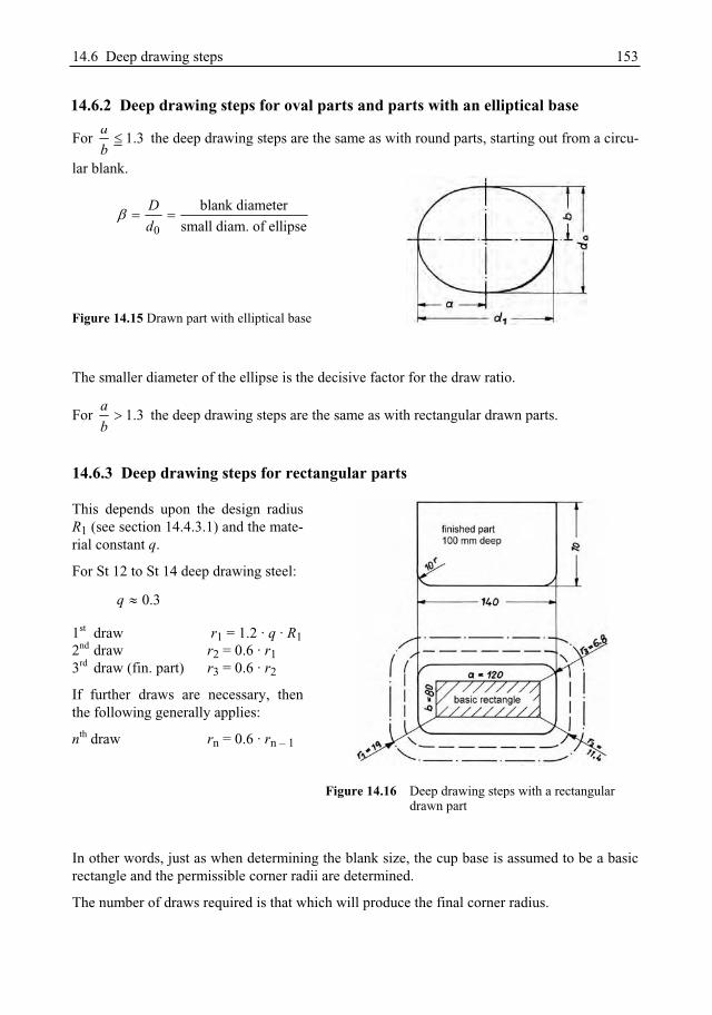
14.6 Deep drawing steps 153
For 1.3ab
the deep drawing steps are the same as with round parts, starting out from a circu-
lar blank.
0
blank diametersmall diam. of ellipse
Dd
Figure 14.15 Drawn part with elliptical base
The smaller diameter of the ellipse is the decisive factor for the draw ratio.
For 1.3ab
the deep drawing steps are the same as with rectangular drawn parts.
14.6.3 Deep drawing steps for rectangular parts
This depends upon the design radius R1 (see section 14.4.3.1) and the mate-rial constant q.
For St 12 to St 14 deep drawing steel:
0.3q
1st draw r1 = 1.2 · q · R12nd draw r2 = 0.6 · r13rd draw (fin. part) r3 = 0.6 · r2
If further draws are necessary, then the following generally applies:
nth draw rn = 0.6 · rn – 1
Figure 14.16 Deep drawing steps with a rectangular drawn part
In other words, just as when determining the blank size, the cup base is assumed to be a basic rectangle and the permissible corner radii are determined.
The number of draws required is that which will produce the final corner radius.
14.6.2 Deep drawing steps for oval parts and parts with an elliptical base

154 14 Deep drawing
Example: Determine the steps for a rectangular drawn part.
Sheet thickness s = 1mm re = rb = 10 mm q = 0.34 R1 = 46.8 mm
1st draw: r1 = 1.2 q · R1 = 1.2 · 0.34 · 46.8 mm = 19 mm 2nd draw: r2 = 0.6 · r1 = 0.6 · 19 mm= 11.4 mm 3rd draw: r3 = 0.6 · r2 = 0.6 · 11.4 mm = 6.84 mm nth draw: r3 = 6.84 mm < 10 mm (< than the radius of the finished part), so the finished part can be produced with three draws.
14.7 Calculating the drawing force
14.7.1 Drawing force for cylindrical parts at the first draw
dr m mF C s R n d s R n
FZ in N drawing force C in mm circumference of the drawing punch d in mm punch diameter s in mm sheet thickness Rm in N/mm2 tensile strength n correction value
The correction value n takes into account the ratio of drawing tension to tensile strength. It depends mainly upon the actual draw ratio, which comes from the dimensions of the drawn part.
Table 14.3 Correction value n = f ( actual)
n 0.2 0.3 0.5 0.7 0.9 1.1 1.3
actualDd
1.1 1.2 1.4 1.6 1.8 2.0 2.2
Table 14.4 Maximum tensile strengths Rm of some deep drawing steels
Material St 1303 St 1404 CuZn28(Ms 72)
Al 99.5 (F10)
Rmmax in N/mm2 400 380 300D. drawing quality
100medium hard

14.8 Blank holder force 155
14.7.2 Drawing force for cylindrical parts at the second draw
drsec 1 m2
FF d s R n
d1 punch diameter at the second draw.
14.7.3 Drawing force for rectangular parts
dr e m4 ( )2
2a bF r R s n
re in mm corner radius (see Figure 14.11) a in mm length of the cup without bottom radius rb (Figure 14.11) b in mm width of the cup without bottom radius rb.
14.8 Blank holder force
14.8.1 Blank holder pressure
m2actual( 1)200 400
d Rps
p in N/mm2 blank holder pressure d in mm punch diameter D in mm diameter of the blank s in mm sheet thickness Rm in N/mm2 tensile strength
actual – actual draw ratio (first draw).
14.8.2 Blank holder area
2 2BH e 4( )A D d
e M2 2d d w r (see Figure 14.17)
ABH in mm2 blank holder area de in mm effective diameter of the blank holder w in mm drawing clearance rM in mm die edge curvature radius.
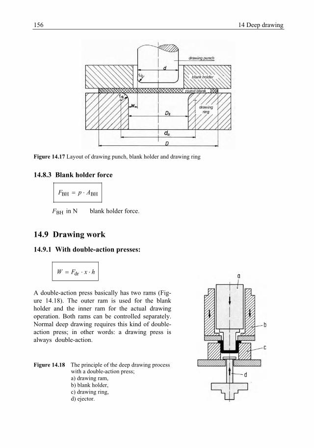
156 14 Deep drawing
Figure 14.17 Layout of drawing punch, blank holder and drawing ring
14.8.3 Blank holder force
BH BHF p A
FBH in N blank holder force.
14.9 Drawing work
14.9.1 With double-action presses:
drW F x h
A double-action press basically has two rams (Fig-ure 14.18). The outer ram is used for the blank holder and the inner ram for the actual drawing operation. Both rams can be controlled separately. Normal deep drawing requires this kind of double-action press; in other words: a drawing press is always double-action.
Figure 14.18 The principle of the deep drawing process with a double-action press;a) drawing ram, b) blank holder, c) drawing ring, d) ejector.
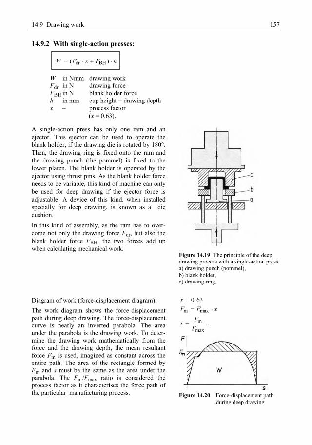
14.9 Drawing work 157
14.9.2 With single-action presses:
dr BH( )W F x F h
W in Nmm drawing work Fdr in N drawing force FBH in N blank holder force h in mm cup height = drawing depth x – process factor (x = 0.63).
A single-action press has only one ram and an ejector. This ejector can be used to operate the blank holder, if the drawing die is rotated by 180°. Then, the drawing ring is fixed onto the ram and the drawing punch (the pommel) is fixed to the lower platen. The blank holder is operated by the ejector using thrust pins. As the blank holder force needs to be variable, this kind of machine can only be used for deep drawing if the ejector force is adjustable. A device of this kind, when installed specially for deep drawing, is known as a die cushion. In this kind of assembly, as the ram has to over-come not only the drawing force Fdr, but also the blank holder force FBH, the two forces add up when calculating mechanical work.
Figure 14.19 The principle of the deep drawing process with a single-action press, a) drawing punch (pommel), b) blank holder, c) drawing ring,
Diagram of work (force-displacement diagram): The work diagram shows the force-displacement path during deep drawing. The force-displacement curve is nearly an inverted parabola. The area under the parabola is the drawing work. To deter-mine the drawing work mathematically from the force and the drawing depth, the mean resultant force Fm is used, imagined as constant across the entire path. The area of the rectangle formed by Fm and s must be the same as the area under the parabola. The Fm/Fmax ratio is considered the process factor as it characterises the force path of the particular manufacturing process.
0,63xm maxF F x
m
max.Fx
F
Figure 14.20 Force-displacement path during deep drawing

158 14 Deep drawing
14.10 Drawing tooling (Figure 14.17)
14.10.1 Drawing clearance w
The drawing clearance, w, is half the difference between the diameter of the drawing ring and the diameter of the punch.
Dw sd
w in mm drawing clearance D in mm diameter of the blank d in mm punch diameter s in mm sheet thickness
For more precise calculations, the following applies (according to Oehler):
w s k s
Table 14.5 Material factor k to determine the drawing clearance w
Material Steel High-temperature alloys Aluminium Other nonferrous
metals
k in mm 0.07 0.2 0.02 0.04
14.10.2 Punch radius rp for cylindrical parts
p (4 ... 5)r s
This depends upon the part being drawn.

14.10 Drawing tooling (Figure 14.17) 159
14.10.3 Die edge curvature rM
For cylindrical parts: Too small radii subject the sheet to additional strain. Too large radii lead to the formation of wrinkles at the end of the draw, as then the blank holder is no longer effective.
M0.035 50 mm ( )
mmr D d s
rM in mm die edge curvature radius D in mm diameter of the blank d in mm diameter of the finished part = punch diameter s in mm sheet thickness
So rM depends upon: the sheet thickness sthe blank diameter Dthe diameter of the finished part d (= punch diameter). With low drawing depths, a smaller rM must be selected as otherwise, the area where the blank holder presses is too small. The parts of the drawing rings which come into contact with the sheet must be kept smoothly ground and polished to reduce frictional forces.
For rectangular parts:
a) for rectangle side a: (see Figure 14.11)
a a e0.035 50 mm 2( )
mmr H r s
b) for rectangle side b:
b b e0.035 50 mm 2( )
mmr H r s
c) radii in the corners of the rectangular die:
e a1.5 .r r
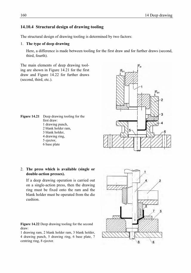
160 14 Deep drawing
14.10.4 Structural design of drawing tooling
The structural design of drawing tooling is determined by two factors:
1. The type of deep drawing
Here, a difference is made between tooling for the first draw and for further draws (second, third, fourth).
The main elements of deep drawing tool-ing are shown in Figure 14.21 for the first draw and Figure 14.22 for further draws (second, third, etc.).
Figure 14.21 Deep drawing tooling for the first draw: 1 drawing punch,2 blank holder ram,3 blank holder,4 drawing ring,5 ejector,6 base plate
2. The press which is available (single or double-action presses).If a deep drawing operation is carried out on a single-action press, then the drawing ring must be fixed onto the ram and the blank holder must be operated from the die cushion.
Figure 14.22 Deep drawing tooling for the second draw:1 drawing ram, 2 blank holder ram, 3 blank holder, 4 drawing punch, 5 drawing ring, 6 base plate, 7 centring ring, 8 ejector.
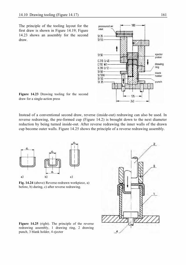
14.10 Drawing tooling (Figure 14.17) 161
The principle of the tooling layout for the first draw is shown in Figure 14.19; Figure 14.23 shows an assembly for the second draw.
Figure 14.23 Drawing tooling for the second draw for a single-action press
Instead of a conventional second draw, reverse (inside-out) redrawing can also be used. In reverse redrawing, the pre-formed cup (Figure 14.2) is brought down to the next diameter reduction by being turned inside-out. After reverse redrawing the inner walls of the drawn cup become outer walls. Figure 14.25 shows the principle of a reverse redrawing assembly.
Fig. 14.24 (above) Reverse-redrawn workpiece, a) before, b) during, c) after reverse redrawing.
Figure 14.25 (right). The principle of the reverse redrawing assembly, 1 drawing ring, 2 drawing punch, 3 blank holder, 4 ejector
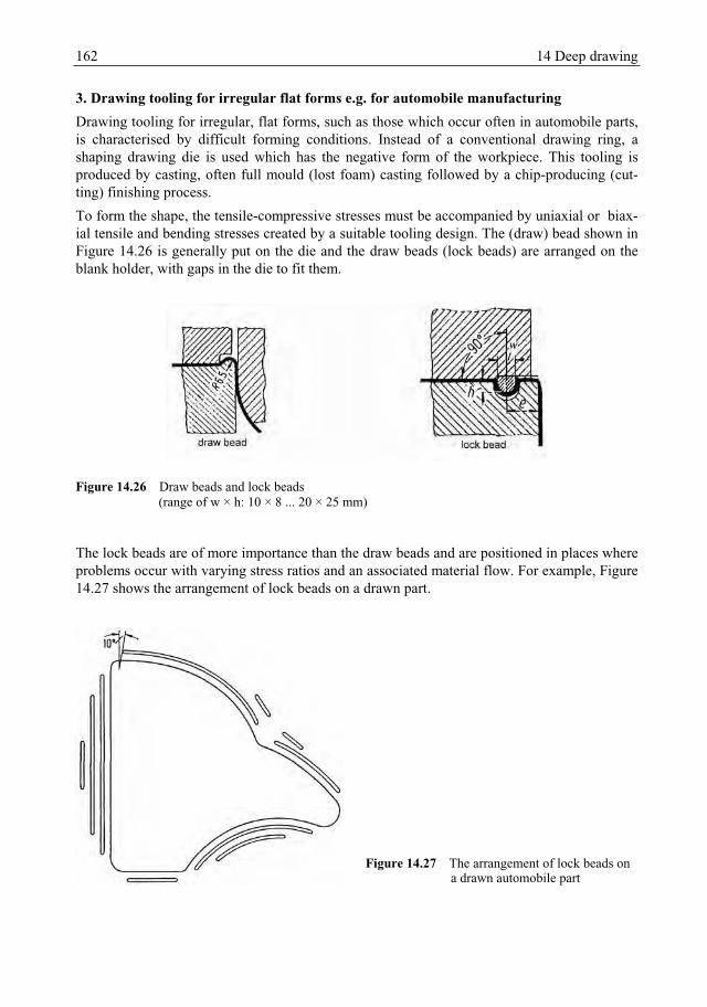
162 14 Deep drawing
3. Drawing tooling for irregular flat forms e.g. for automobile manufacturing Drawing tooling for irregular, flat forms, such as those which occur often in automobile parts, is characterised by difficult forming conditions. Instead of a conventional drawing ring, a shaping drawing die is used which has the negative form of the workpiece. This tooling is produced by casting, often full mould (lost foam) casting followed by a chip-producing (cut-ting) finishing process. To form the shape, the tensile-compressive stresses must be accompanied by uniaxial or biax-ial tensile and bending stresses created by a suitable tooling design. The (draw) bead shown in Figure 14.26 is generally put on the die and the draw beads (lock beads) are arranged on the blank holder, with gaps in the die to fit them.
Figure 14.26 Draw beads and lock beads (range of w × h: 10 × 8 ... 20 × 25 mm)
The lock beads are of more importance than the draw beads and are positioned in places where problems occur with varying stress ratios and an associated material flow. For example, Figure 14.27 shows the arrangement of lock beads on a drawn part.
Figure 14.27 The arrangement of lock beads on a drawn automobile part
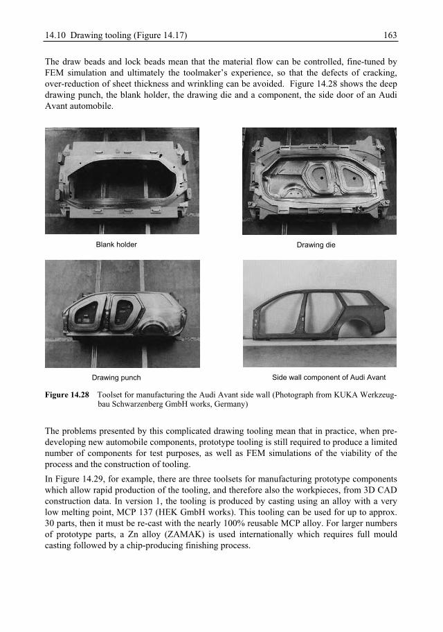
14.10 Drawing tooling (Figure 14.17) 163
The draw beads and lock beads mean that the material flow can be controlled, fine-tuned by FEM simulation and ultimately the toolmaker’s experience, so that the defects of cracking, over-reduction of sheet thickness and wrinkling can be avoided. Figure 14.28 shows the deep drawing punch, the blank holder, the drawing die and a component, the side door of an Audi Avant automobile.
Blank holder Drawing die
Drawing punch Side wall component of Audi Avant
Figure 14.28 Toolset for manufacturing the Audi Avant side wall (Photograph from KUKA Werkzeug-bau Schwarzenberg GmbH works, Germany)
The problems presented by this complicated drawing tooling mean that in practice, when pre-developing new automobile components, prototype tooling is still required to produce a limited number of components for test purposes, as well as FEM simulations of the viability of the process and the construction of tooling. In Figure 14.29, for example, there are three toolsets for manufacturing prototype components which allow rapid production of the tooling, and therefore also the workpieces, from 3D CAD construction data. In version 1, the tooling is produced by casting using an alloy with a very low melting point, MCP 137 (HEK GmbH works). This tooling can be used for up to approx. 30 parts, then it must be re-cast with the nearly 100% reusable MCP alloy. For larger numbers of prototype parts, a Zn alloy (ZAMAK) is used internationally which requires full mould casting followed by a chip-producing finishing process.
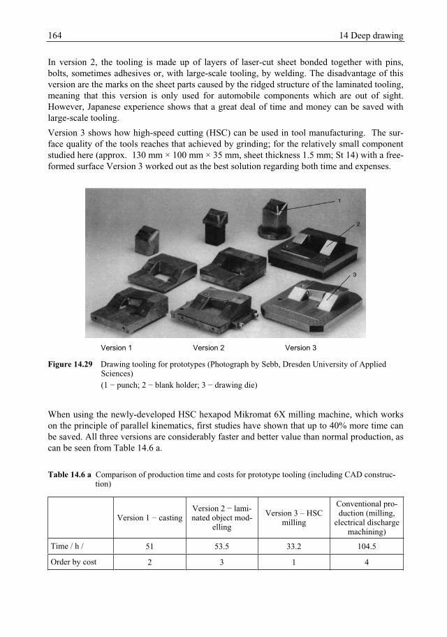
164 14 Deep drawing
In version 2, the tooling is made up of layers of laser-cut sheet bonded together with pins, bolts, sometimes adhesives or, with large-scale tooling, by welding. The disadvantage of this version are the marks on the sheet parts caused by the ridged structure of the laminated tooling, meaning that this version is only used for automobile components which are out of sight. However, Japanese experience shows that a great deal of time and money can be saved with large-scale tooling.Version 3 shows how high-speed cutting (HSC) can be used in tool manufacturing. The sur-face quality of the tools reaches that achieved by grinding; for the relatively small component studied here (approx. 130 mm × 100 mm × 35 mm, sheet thickness 1.5 mm; St 14) with a free-formed surface Version 3 worked out as the best solution regarding both time and expenses.
Version 1 Version 2 Version 3
Figure 14.29 Drawing tooling for prototypes (Photograph by Sebb, Dresden University of Applied Sciences) (1 punch; 2 blank holder; 3 drawing die)
When using the newly-developed HSC hexapod Mikromat 6X milling machine, which works on the principle of parallel kinematics, first studies have shown that up to 40% more time can be saved. All three versions are considerably faster and better value than normal production, as can be seen from Table 14.6 a.
Table 14.6 a Comparison of production time and costs for prototype tooling (including CAD construc-tion)
Version 1 castingVersion 2 lami-nated object mod-
elling
Version 3 – HSC milling
Conventional pro-duction (milling,
electrical discharge machining)
Time / h / 51 53.5 33.2 104.5
Order by cost 2 3 1 4
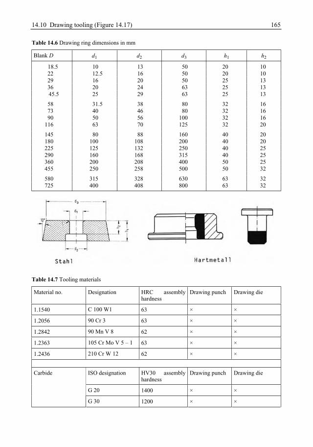
14.10 Drawing tooling (Figure 14.17) 165
Table 14.6 Drawing ring dimensions in mm
Blank D d1 d2 d3 h1 h2
18.5 10 13 50 20 1022 12.5 16 50 20 1029 16 20 50 25 1336 20 24 63 25 1345.5 25 29 63 25 13
58 31.5 38 80 32 1673 40 46 80 32 1690 50 56 100 32 16
116 63 70 125 32 20
145 80 88 160 40 20180 100 108 200 40 20225 125 132 250 40 25290 160 168 315 40 25360 200 208 400 50 25455 250 258 500 50 32
580 315 328 630 63 32725 400 408 800 63 32
Table 14.7 Tooling materials
Material no. Designation HRC assembly hardness
Drawing punch Drawing die
1.1540 C 100 W1 63 × ×
1.2056 90 Cr 3 63 × ×
1.2842 90 Mn V 8 62 × ×
1.2363 105 Cr Mo V 5 – 1 63 × ×
1.2436 210 Cr W 12 62 × ×
ISO designation HV30 assembly hardness
Drawing punch Drawing die
G 20 1400 × ×
Carbide
G 30 1200 × ×
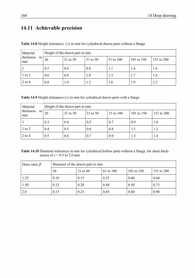
166 14 Deep drawing
14.11 Achievable precision
Table 14.8 Height tolerances (±) in mm for cylindrical drawn parts without a flange
Height of the drawn part in mm Materialthickness in mm 20 21 to 30 31 to 50 51 to 100 101 to 150 151 to 200
1 0.5 0.6 0.8 1.1 1.4 1.6
1 to 2 0.6 0.8 1.0 1.3 1.7 1.8
2 to 4 0.8 1.0 1.2 1.6 1.9 2.2
Table 14.9 Height tolerances (±) in mm for cylindrical drawn parts with a flange
Height of the drawn part in mm Materialthickness in mm 20 21 to 30 31 to 50 51 to 100 101 to 150 151 to 200
1 0.3 0.4 0.5 0.7 0.9 1.0
1 to 2 0.4 0.5 0.6 0.8 1.1 1.2
2 to 4 0.5 0.6 0.7 0.9 1.3 1.4
Table 14.10 Diameter tolerances in mm for cylindrical hollow parts without a flange, for sheet thick-nesses of s = 0.5 to 2.0 mm
Diameter of the drawn part in mm Draw ratio
30 31 to 60 61 to 100 101 to 150 151 to 200
1.25 0.10 0.15 0.25 0.40 0.60
1.50 0.12 0.20 0.40 0.50 0.75
2.0 0.15 0.25 0.45 0.60 0.90
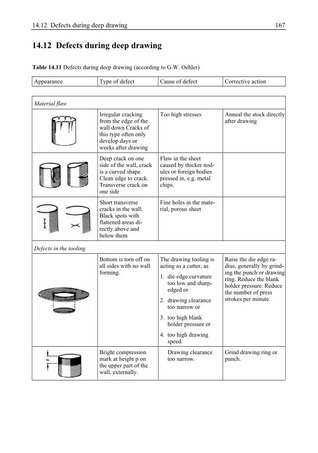
14.12 Defects during deep drawing 167
14.12 Defects during deep drawing
Table 14.11 Defects during deep drawing (according to G.W. Oehler)
Appearance Type of defect Cause of defect Corrective action
Material flaw
Irregular cracking from the edge of the wall down Cracks of this type often only develop days or weeks after drawing
Too high stresses Anneal the stock directly after drawing
Deep crack on one side of the wall, crack is a curved shape. Clean edge to crack. Transverse crack on one side
Flaw in the sheet caused by thicker nod-ules or foreign bodies pressed in, e.g. metal chips.
Short transverse cracks in the wall. Black spots with flattened areas di-rectly above and below them
Fine holes in the mate-rial, porous sheet
Defects in the tooling
Bottom is torn off on all sides with no wall forming.
The drawing tooling is acting as a cutter, as
1. die edge curvature too low and sharp-edged or
2. drawing clearance too narrow or
3. too high blank holder pressure or
4. too high drawing speed.
Raise the die edge ra-dius, generally by grind-ing the punch or drawing ring. Reduce the blank holder pressure. Reduce the number of press strokes per minute.
Bright compression mark at height p on the upper part of the wall, externally.
Drawing clearance too narrow.
Grind drawing ring or punch.
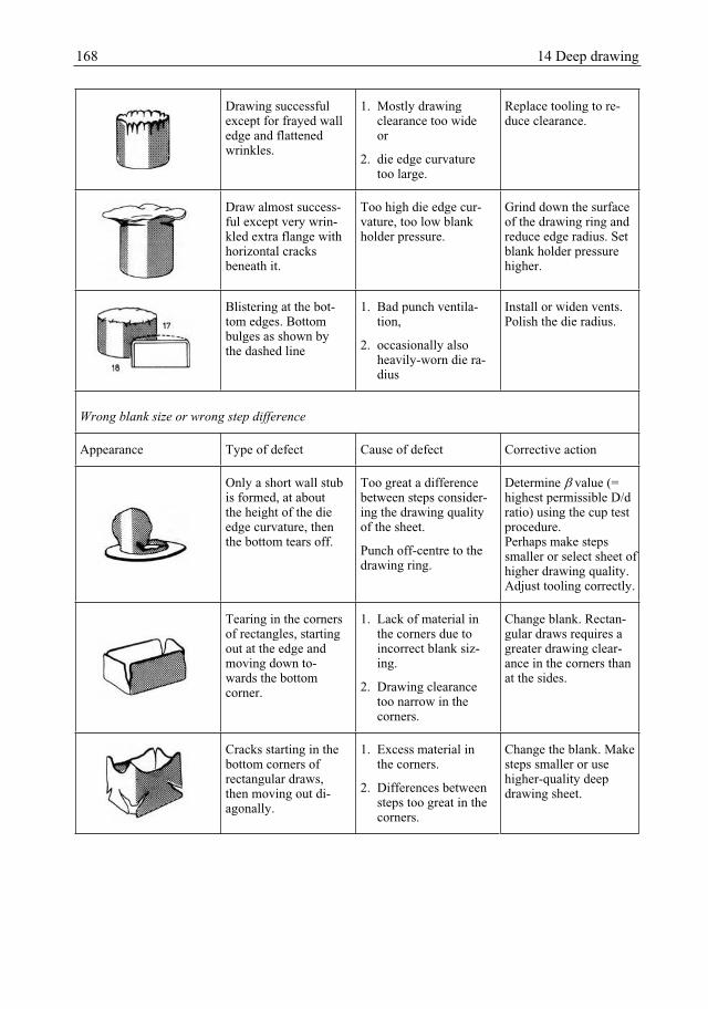
168 14 Deep drawing
Drawing successful except for frayed wall edge and flattened wrinkles.
1. Mostly drawing clearance too wide or
2. die edge curvature too large.
Replace tooling to re-duce clearance.
Draw almost success-ful except very wrin-kled extra flange with horizontal cracks beneath it.
Too high die edge cur-vature, too low blank holder pressure.
Grind down the surface of the drawing ring and reduce edge radius. Set blank holder pressure higher.
Blistering at the bot-tom edges. Bottom bulges as shown by the dashed line
1. Bad punch ventila-tion,
2. occasionally also heavily-worn die ra-dius
Install or widen vents. Polish the die radius.
Wrong blank size or wrong step difference
Appearance Type of defect Cause of defect Corrective action
Only a short wall stub is formed, at about the height of the die edge curvature, then the bottom tears off.
Too great a difference between steps consider-ing the drawing quality of the sheet.
Punch off-centre to the drawing ring.
Determine value (= highest permissible D/d ratio) using the cup test procedure.Perhaps make steps smaller or select sheet of higher drawing quality. Adjust tooling correctly.
Tearing in the corners of rectangles, starting out at the edge and moving down to-wards the bottom corner.
1. Lack of material in the corners due to incorrect blank siz-ing.
2. Drawing clearance too narrow in the corners.
Change blank. Rectan-gular draws requires a greater drawing clear-ance in the corners than at the sides.
Cracks starting in the bottom corners of rectangular draws, then moving out di-agonally.
1. Excess material in the corners.
2. Differences between steps too great in the corners.
Change the blank. Make steps smaller or use higher-quality deep drawing sheet.
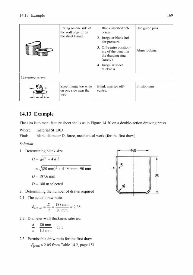
14.13 Example 169
Earing on one side of the wall edge or on the sheet flange.
1. Blank inserted off-centre.
2. Irregular blank hol-der pressure.
3. Off-centre position-ing of the punch in the drawing ring (rarely).
4. Irregular sheet thickness
Use guide pins.
Align tooling.
Operating errors
Sheet flange too wide on one side near the web.
Blank inserted off-centre.
Fit stop pins.
14.13 Example The aim is to manufacture sheet shells as in Figure 14.30 on a double-action drawing press.
Where: material St 1303 Find: blank diameter D, force, mechanical work (for the first draw)
Solution:
1. Determining blank size
2 4D d d h
2(80 mm) 4 80 mm 90 mm
187.6 mmD
188 m selectedD
2. Determining the number of draws required 2.1. The actual draw ratio
actual188 mm 2.3580 mm
Dd
2.2. Diameter-wall thickness ratio d/s80 mm 53.31.5 mm
ds
2.3. Permissible draw ratio for the first draw
perm 2.05 from Table 14.2, page 151

170 14 Deep drawing
2.4. Decision
as 0 perm actual
2.05 2.35
the part can not be produced in one draw as in Figure 14.26.
2.5. Deep drawing steps
1. draw 10
188 mm 91.7 mm2.05
Dd
12
1
91.7 mm 70.5 mm1.3
dd
i.e. the drawn part can be produced with two draws.
So that it is not necessary to go up to the deformability limit at the first draw,
d1 = 94.0 mm is selected.
Thus
actual188 mm 2.094 mm
At the second draw, this then produces an actual of
1actual
2
94 mm 1.1780 mm
dd
i.e. d2 will also be safely achieved.
2.6. Height of the cup after the first draw
From 2 4D d d h we get:
2 2 2 2 2 21
(188 mm) (94 mm) 35 344 mm 8836 mm4 4 94 mm 376 mm
D dhd
h1 = 70.5 mm.

14.13 Example 171
As slight earing is to be expected, h = 70.5 mm + 1.5 mm = 72 mm is assumed.
3. Drawing force Fdr
2dr m 94 mm 1.5 mm 400 N/ mm 1.1F d s R n
dr 194 904 N 195 kNF
For ( actual = 2.0 then n = 1.1 from Table 14.3, Rm = 400 N/mm2 from Table 14.4.
4. Drawing clearance w
188 mm1.5 mm 2.12 mm94 mm
Dw sd
w = 2.1 selected.
5. Die edge curvature rM
M0.035 [50 mm ( )]
mmr D d s
M0.035 [50 mm (188 mm 94 mm)] 1.5 mm
mmr
rM = 6.17 mm rM = 6.0 mm selected.
6. Blank holder force FBH
6.1. Blank holder pressure
m2actual( 1)200 400
d Rps
22 294 400 N/ mm(2 1) 1.31 N/ mm .
200 1.5 mm 400
6.2. Blank holder area (see Figure 14.17) de = d + 2 · w + 2 · rM = 94 mm + 2 · 2.1 mm + 2 · 6 mm = 110.2 mm
2 2 2 2 2BH e 4 4( ) (188 110.2 ) 18 221.2 mmA D d
6.3. Blank holder force FBH = ABH · p = 18 221.2 mm2 · 1.31 N/mm2 = 23 869 N = 23.9 kN.
7. Work WW = Fdr · x · h1 = 195 kN · 0.63 · 0.072 m = 8.84 kNm.

172 14 Deep drawing
14.14 Hydromechanical deep drawing (HDD)
14.14.1 Definitions In hydromechanical deep drawing (Figure 14.31) the circular blank to be formed (first draw) is pressed directly onto the downward-moving drawing die by a pressurised water pad giving it the exact shape of the drawing punch.
Figure 14.31 The principle of hydromechanical deep drawing, a) before, b) during, c) at the end of the first draw. 1 drawing punch, 2 blank holder, 3 blank, 4 drawing ring, 5 seal, 6 water chamber
For the second draw (Figure 14.32) the process is similar. Here, the outer diameter of the blankholder is the inner diameter of the cup after the first draw. This means that before the second draw, the cup is centred in the blank holder. The punch has the new, reduced diameter to be produced in the second draw.
Figure 14.32 Tooling for the second draw:1 drawing punch, 2 blank holder,3 workpiece before the 2nd draw, 4 drawing ring,5 water chamber
14.14.2 Advantages of hydromechanical deep drawing When a processing medium is used in place of the rigid drawing ring, as the punch is moved down, this processing medium produces pressure on all sides, pressing the workpiece being formed onto the punch.
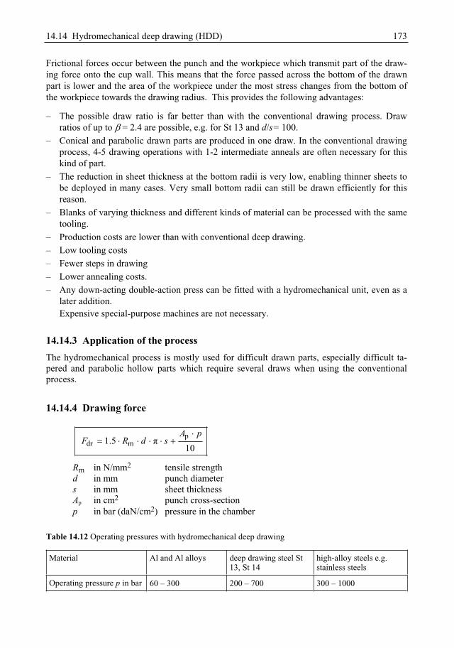
14.14 Hydromechanical deep drawing (HDD) 173
Frictional forces occur between the punch and the workpiece which transmit part of the draw-ing force onto the cup wall. This means that the force passed across the bottom of the drawn part is lower and the area of the workpiece under the most stress changes from the bottom of the workpiece towards the drawing radius. This provides the following advantages:
– The possible draw ratio is far better than with the conventional drawing process. Draw ratios of up to = 2.4 are possible, e.g. for St 13 and d/s= 100.
– Conical and parabolic drawn parts are produced in one draw. In the conventional drawing process, 4-5 drawing operations with 1-2 intermediate anneals are often necessary for this kind of part.
– The reduction in sheet thickness at the bottom radii is very low, enabling thinner sheets to be deployed in many cases. Very small bottom radii can still be drawn efficiently for this reason.
– Blanks of varying thickness and different kinds of material can be processed with the same tooling.
– Production costs are lower than with conventional deep drawing. – Low tooling costs – Fewer steps in drawing – Lower annealing costs. – Any down-acting double-action press can be fitted with a hydromechanical unit, even as a
later addition. Expensive special-purpose machines are not necessary.
14.14.3 Application of the process The hydromechanical process is mostly used for difficult drawn parts, especially difficult ta-pered and parabolic hollow parts which require several draws when using the conventional process.
14.14.4 Drawing force
pdr m1.5
10A p
F R d s
Rm in N/mm2 tensile strength d in mm punch diameter s in mm sheet thickness Ap in cm2 punch cross-section p in bar (daN/cm2) pressure in the chamber
Table 14.12 Operating pressures with hydromechanical deep drawing
Material Al and Al alloys deep drawing steel St 13, St 14
high-alloy steels e.g. stainless steels
Operating pressure p in bar 60 – 300 200 – 700 300 – 1000
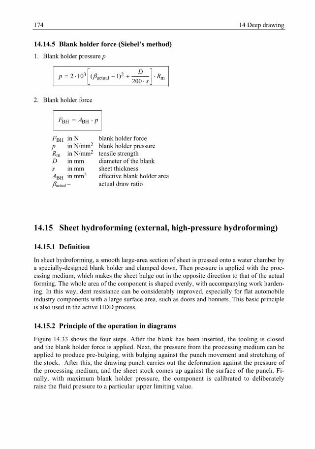
174 14 Deep drawing
14.14.5 Blank holder force (Siebel’s method) 1. Blank holder pressure p
3 2actual m2 10 ( 1)200
Dp Rs
2. Blank holder force
BH BHF A p
FBH in N blank holder force p in N/mm2 blank holder pressure Rm in N/mm2 tensile strength D in mm diameter of the blank s in mm sheet thickness ABH in mm2 effective blank holder area
actual – actual draw ratio
14.15 Sheet hydroforming (external, high-pressure hydroforming)
14.15.1 Definition
In sheet hydroforming, a smooth large-area section of sheet is pressed onto a water chamber by a specially-designed blank holder and clamped down. Then pressure is applied with the proc-essing medium, which makes the sheet bulge out in the opposite direction to that of the actual forming. The whole area of the component is shaped evenly, with accompanying work harden-ing. In this way, dent resistance can be considerably improved, especially for flat automobile industry components with a large surface area, such as doors and bonnets. This basic principle is also used in the active HDD process.
14.15.2 Principle of the operation in diagrams
Figure 14.33 shows the four steps. After the blank has been inserted, the tooling is closed and the blank holder force is applied. Next, the pressure from the processing medium can be applied to produce pre-bulging, with bulging against the punch movement and stretching of the stock. After this, the drawing punch carries out the deformation against the pressure of the processing medium, and the sheet stock comes up against the surface of the punch. Fi-nally, with maximum blank holder pressure, the component is calibrated to deliberately raise the fluid pressure to a particular upper limiting value.
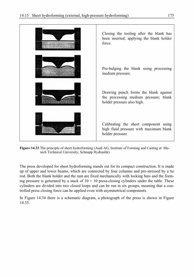
14.15 Sheet hydroforming (external, high-pressure hydroforming) 175
Closing the tooling after the blank has been inserted; applying the blank holder force.
Pre-bulging the blank using processing medium pressure.
Drawing punch forms the blank against the processing medium pressure; blank holder pressure also high.
Calibrating the sheet component using high fluid pressure with maximum blank holder pressure
Figure 14.33 The principle of sheet hydroforming (Audi AG, Institute of Forming and Casting at Mu-nich Technical University, Schnupp Hydraulik)
The press developed for sheet hydroforming stands out for its compact construction. It is made up of upper and lower beams, which are connected by four columns and pre-stressed by a tie rod. Both the blank holder and the ram are fixed mechanically with locking bars and the form-ing pressure is generated by a stack of 10 × 10 press-closing cylinders under the table. These cylinders are divided into two closed loops and can be run in six groups, meaning that a con-trolled press closing force can be applied even with asymmetrical components.
In Figure 14.34 there is a schematic diagram, a photograph of the press is shown in Figure 14.35.
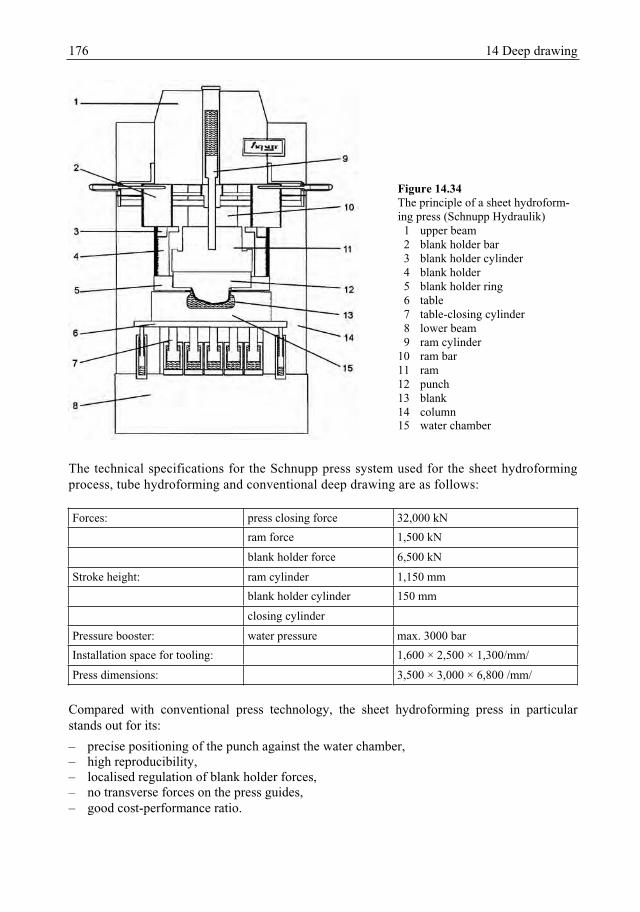
176 14 Deep drawing
Figure 14.34 The principle of a sheet hydroform-ing press (Schnupp Hydraulik) 1 upper beam 2 blank holder bar 3 blank holder cylinder 4 blank holder 5 blank holder ring 6 table 7 table-closing cylinder 8 lower beam 9 ram cylinder 10 ram bar 11 ram 12 punch 13 blank 14 column 15 water chamber
The technical specifications for the Schnupp press system used for the sheet hydroforming process, tube hydroforming and conventional deep drawing are as follows:
Forces: press closing force 32,000 kN ram force 1,500 kN
blank holder force 6,500 kN
Stroke height: ram cylinder 1,150 mm blank holder cylinder 150 mm
closing cylinder
Pressure booster: water pressure max. 3000 bar Installation space for tooling: 1,600 × 2,500 × 1,300/mm/
Press dimensions: 3,500 × 3,000 × 6,800 /mm/
Compared with conventional press technology, the sheet hydroforming press in particular stands out for its: – precise positioning of the punch against the water chamber, – high reproducibility, – localised regulation of blank holder forces, – no transverse forces on the press guides, – good cost-performance ratio.
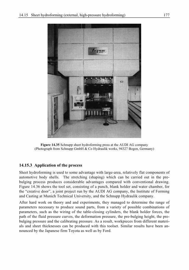
14.15 Sheet hydroforming (external, high-pressure hydroforming) 177
Figure 14.35 Schnupp sheet hydroforming press at the AUDI AG company (Photograph from Schnupp GmbH & Co Hydraulik works, 94327 Bogen, Germany)
14.15.3 Application of the process Sheet hydroforming is used to some advantage with large-area, relatively flat components of automotive body shells. The stretching (shaping) which can be carried out in the pre-bulging process produces considerable advantages compared with conventional drawing. Figure 14.36 shows the tool set, consisting of a punch, blank holder and water chamber, for the “creative door”, a joint project run by the AUDI AG company, the Institute of Forming and Casting at Munich Technical University, and the Schnupp Hydraulik company. After hard work on theory and and experiments, they managed to determine the range of parameters necessary to produce sound parts, from a variety of possible combinations of parameters, such as the wiring of the table-closing cylinders, the blank holder forces, the path of the fluid pressure curves, the deformation pressure, the pre-bulging height, the pre-bulging pressure and the calibrating pressure. As a result, workpieces from different materi-als and sheet thicknesses can be produced with this toolset. Similar results have been an-nounced by the Japanese firm Toyota as well as by Ford.
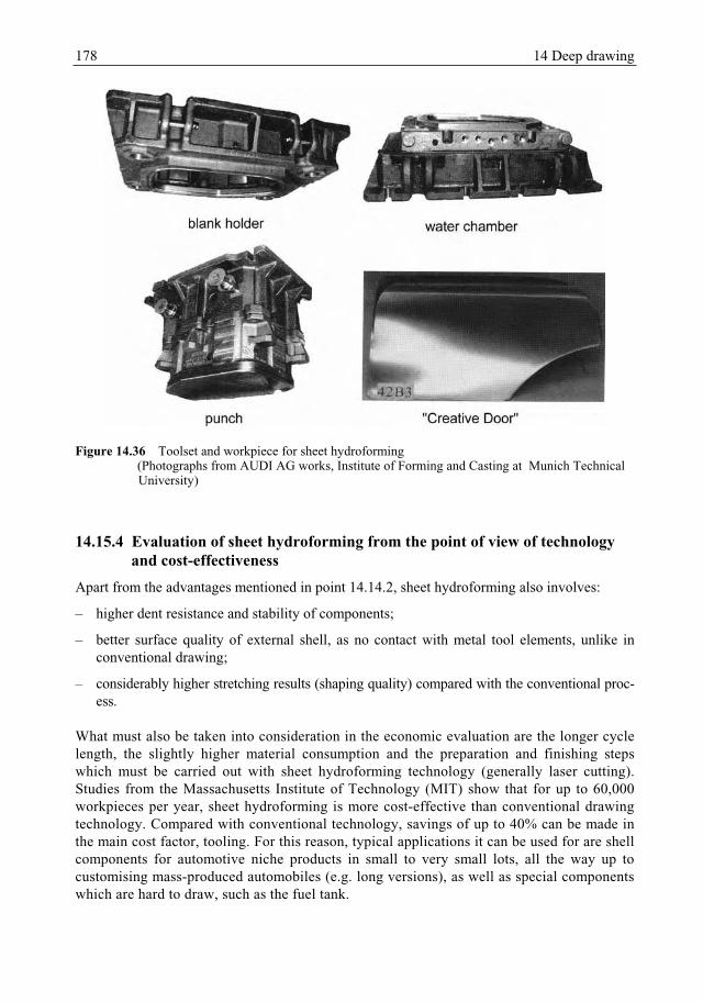
178 14 Deep drawing
Figure 14.36 Toolset and workpiece for sheet hydroforming (Photographs from AUDI AG works, Institute of Forming and Casting at Munich Technical University)
14.15.4 Evaluation of sheet hydroforming from the point of view of technology and cost-effectiveness
Apart from the advantages mentioned in point 14.14.2, sheet hydroforming also involves:
– higher dent resistance and stability of components;
– better surface quality of external shell, as no contact with metal tool elements, unlike in conventional drawing;
– considerably higher stretching results (shaping quality) compared with the conventional proc-ess.
What must also be taken into consideration in the economic evaluation are the longer cycle length, the slightly higher material consumption and the preparation and finishing steps which must be carried out with sheet hydroforming technology (generally laser cutting). Studies from the Massachusetts Institute of Technology (MIT) show that for up to 60,000 workpieces per year, sheet hydroforming is more cost-effective than conventional drawing technology. Compared with conventional technology, savings of up to 40% can be made in the main cost factor, tooling. For this reason, typical applications it can be used for are shell components for automotive niche products in small to very small lots, all the way up to customising mass-produced automobiles (e.g. long versions), as well as special components which are hard to draw, such as the fuel tank.
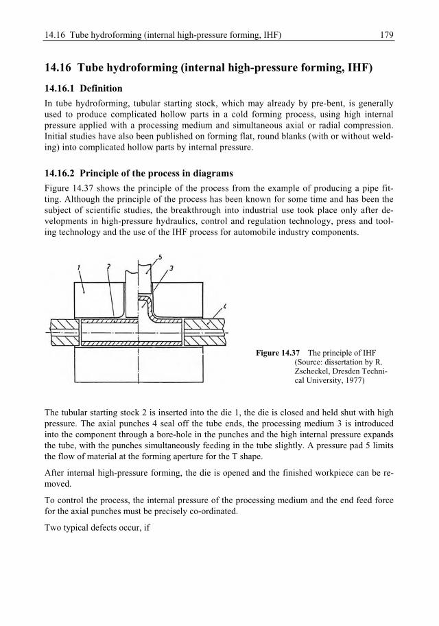
14.16 Tube hydroforming (internal high-pressure forming, IHF) 179
14.16 Tube hydroforming (internal high-pressure forming, IHF)
14.16.1 Definition In tube hydroforming, tubular starting stock, which may already by pre-bent, is generally used to produce complicated hollow parts in a cold forming process, using high internal pressure applied with a processing medium and simultaneous axial or radial compression. Initial studies have also been published on forming flat, round blanks (with or without weld-ing) into complicated hollow parts by internal pressure.
14.16.2 Principle of the process in diagrams Figure 14.37 shows the principle of the process from the example of producing a pipe fit-ting. Although the principle of the process has been known for some time and has been the subject of scientific studies, the breakthrough into industrial use took place only after de-velopments in high-pressure hydraulics, control and regulation technology, press and tool-ing technology and the use of the IHF process for automobile industry components.
Figure 14.37 The principle of IHF (Source: dissertation by R. Zscheckel, Dresden Techni-cal University, 1977)
The tubular starting stock 2 is inserted into the die 1, the die is closed and held shut with high pressure. The axial punches 4 seal off the tube ends, the processing medium 3 is introduced into the component through a bore-hole in the punches and the high internal pressure expands the tube, with the punches simultaneously feeding in the tube slightly. A pressure pad 5 limits the flow of material at the forming aperture for the T shape.
After internal high-pressure forming, the die is opened and the finished workpiece can be re-moved.
To control the process, the internal pressure of the processing medium and the end feed force for the axial punches must be precisely co-ordinated.
Two typical defects occur, if
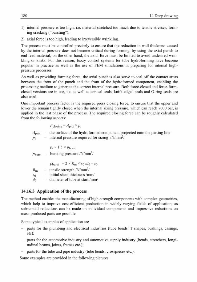
180 14 Deep drawing
1) internal pressure is too high, i.e. material stretched too much due to tensile stresses, form-ing cracking (“bursting”);
2) axial force is too high, leading to irreversible wrinkling. The process must be controlled precisely to ensure that the reduction in wall thickness caused by the internal pressure does not become critical during forming, by using the axial punch to end feed material; on the other hand, the axial force must be limited to avoid undesired wrin-kling or kinks. For this reason, fuzzy control systems for tube hydroforming have become popular in practice as well as the use of FEM simulations in preparing for internal high-pressure processes. As well as providing forming force, the axial punches also serve to seal off the contact areas between the front of the punch and the front of the hydroformed component, enabling the processing medium to generate the correct internal pressure. Both force-closed and force-form-closed versions are in use, i.e. as well as conical seals, knife-edged seals and O-ring seals are also used. One important process factor is the required press closing force, to ensure that the upper and lower die remain tightly closed when the internal sizing pressure, which can reach 7000 bar, is applied in the last phase of the process. The required closing force can be roughly calculated from the following aspects:
Fclosing = Aproj × pi
Aproj – the surface of the hydroformed component projected onto the parting line pi – internal pressure required for sizing /N/mm2/
pi ~ 1.5 × pburst
pburst – bursting pressure /N/mm2/
pburst = 2 × Rm × s0 /d0 – s0
Rm – tensile strength /N/mm2/s0 – initial sheet thickness /mm/ d0 – diameter of tube at start /mm/
14.16.3 Application of the process The method enables the manufacturing of high-strength components with complex geometries, which help to improve cost-efficient production in widely-varying fields of application, as substantial reductions can be made on individual components and impressive reductions on mass-produced parts are possible.
Some typical examples of application are – parts for the plumbing and electrical industries (tube bends, T shapes, bushings, casings,
etc);– parts for the automotive industry and automotive supply industry (bends, stretchers, longi-
tudinal beams, joints, frames etc.); – parts for the tube and pipe industry (tube bends, crosspieces etc.).
Some examples are provided in the following pictures.
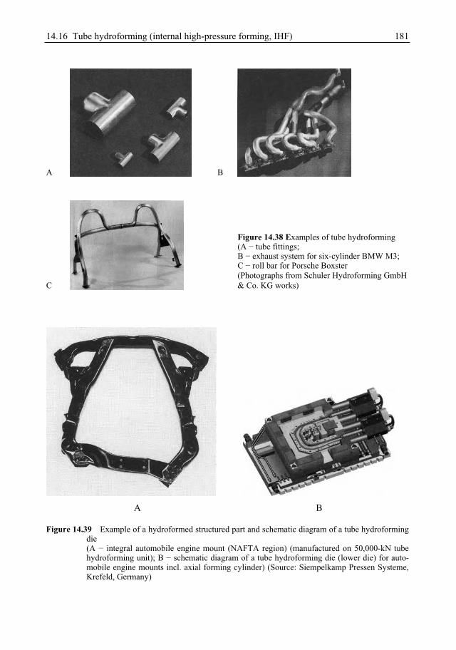
14.16 Tube hydroforming (internal high-pressure forming, IHF) 181
A B
C
Figure 14.38 Examples of tube hydroforming (A tube fittings;B exhaust system for six-cylinder BMW M3; C roll bar for Porsche Boxster (Photographs from Schuler Hydroforming GmbH & Co. KG works)
A B
Figure 14.39 Example of a hydroformed structured part and schematic diagram of a tube hydroforming die(A integral automobile engine mount (NAFTA region) (manufactured on 50,000-kN tube hydroforming unit); B schematic diagram of a tube hydroforming die (lower die) for auto-mobile engine mounts incl. axial forming cylinder) (Source: Siempelkamp Pressen Systeme, Krefeld, Germany)
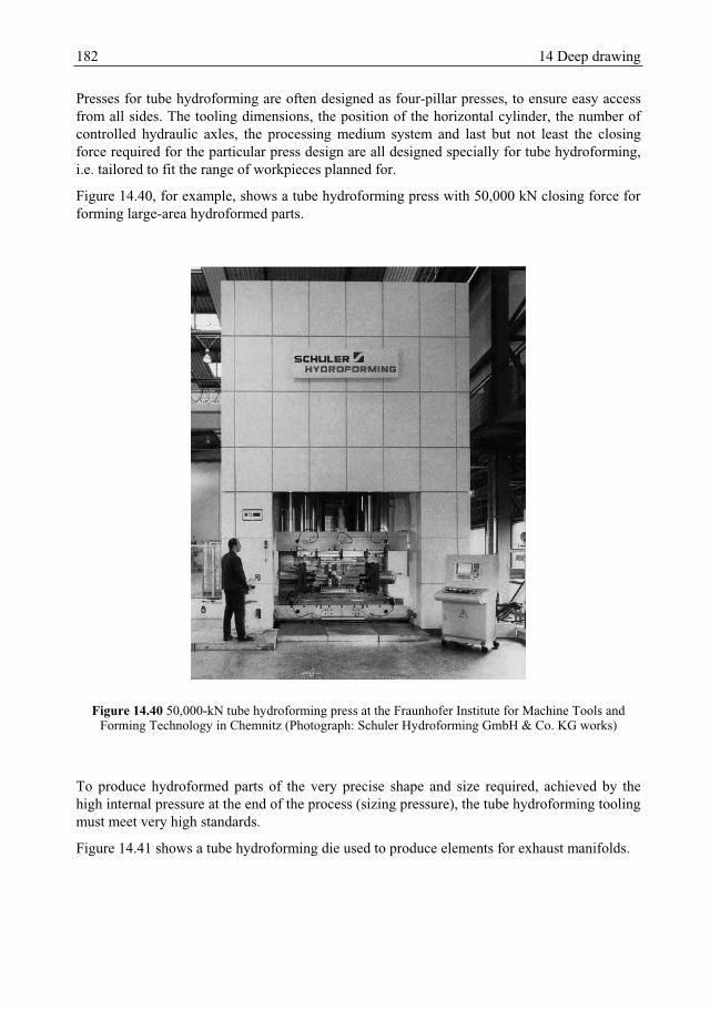
182 14 Deep drawing
Presses for tube hydroforming are often designed as four-pillar presses, to ensure easy access from all sides. The tooling dimensions, the position of the horizontal cylinder, the number of controlled hydraulic axles, the processing medium system and last but not least the closing force required for the particular press design are all designed specially for tube hydroforming, i.e. tailored to fit the range of workpieces planned for.
Figure 14.40, for example, shows a tube hydroforming press with 50,000 kN closing force for forming large-area hydroformed parts.
Figure 14.40 50,000-kN tube hydroforming press at the Fraunhofer Institute for Machine Tools and Forming Technology in Chemnitz (Photograph: Schuler Hydroforming GmbH & Co. KG works)
To produce hydroformed parts of the very precise shape and size required, achieved by the high internal pressure at the end of the process (sizing pressure), the tube hydroforming tooling must meet very high standards.
Figure 14.41 shows a tube hydroforming die used to produce elements for exhaust manifolds.
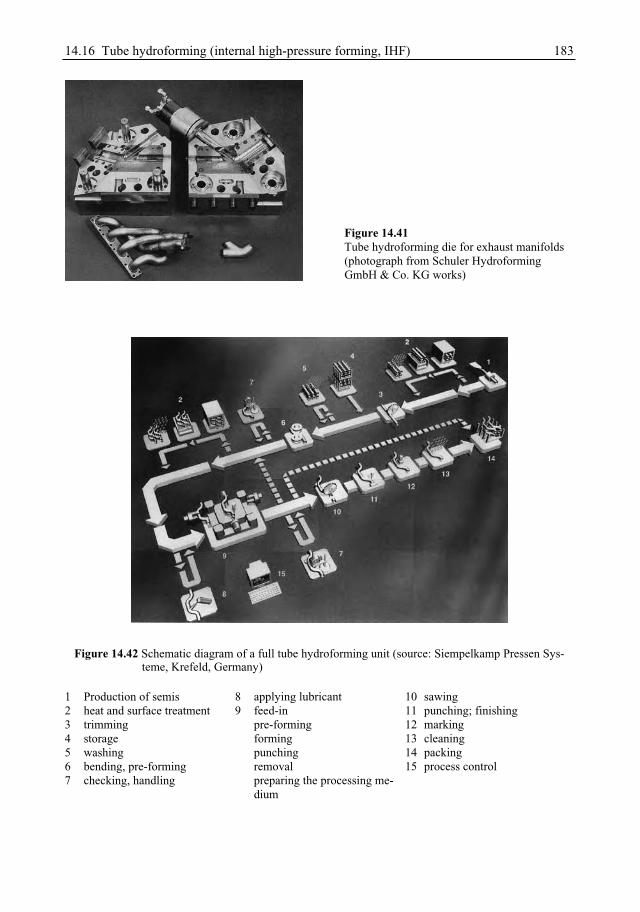
14.16 Tube hydroforming (internal high-pressure forming, IHF) 183
Figure 14.41 Tube hydroforming die for exhaust manifolds (photograph from Schuler Hydroforming GmbH & Co. KG works)
Figure 14.42 Schematic diagram of a full tube hydroforming unit (source: Siempelkamp Pressen Sys-teme, Krefeld, Germany)
1 Production of semis 2 heat and surface treatment 3 trimming 4 storage 5 washing 6 bending, pre-forming 7 checking, handling
8 applying lubricant 9 feed-in
pre-forming forming punchingremovalpreparing the processing me-dium
10 sawing 11 punching; finishing 12 marking 13 cleaning 14 packing 15 process control

184 14 Deep drawing
The disadvantage of the sometimes relatively long cycle compared with competing processes, which affects the number of parts which can be produced economically, is often balanced out by the superior qualities of the tube hydroformed components. The cost-effective production of IHF parts is only possible when the process is seen as a whole, from the pre-treatment of the starting stock, to heat and surface treatment, up to finishing. Figure 14.42 shows an example of a complete tube hydroforming unit.
14.16.3 Advantages of tube hydroforming The crucial advantages of tube hydroforming are: – the production of complicated components which could previously only be produced from
several separate parts, – very precise sizing and shaping of components, – increase in strength due to work hardening, – low weight with optimum strengh, – high rigidity, – high fatigue strength, – fewer welding joints for complex components, – low flow resistance (exhaust systems).
14.17 Exercise on Chapter 14 1. What kind of forming process is deep drawing? 2. Name typical workpieces which are produced using this process. 3. What are “characteristic triangles” and how are they formed? 4. Why can it be assumed that the surface of the workpiece and blank is equal when determin-
ing the blank dimensions? 5. Name the most important elements of deep drawing tooling. 6. How is the drawing tooling for the first draw different to that for the second draw? 7. What happens when the blank holder pressure is too low and what happens when it is too
high? 8. Name the most important advantages of sheet hydroforming. 9. What main areas of application for sheet hydroforming do you know? Name their eco-
nomic limits. 10. Explain the priniple of the tube hydroforming (IHF) process. 11. Name typical workpieces which are produced using these processes. 12. How can the process factor of closing force be roughly calculated? 13. Name the most important advantages of tube hydroforming (IHF). 14. What typical defects occur with tube hydroforming?

15 Deep drawing without a blank holder; metal spin
15.1 Deep drawing without a blank holder When deep drawing without a blank holder, the die assembly is simpler as the blank holder is not used. What is more, deep drawing without a blank holder can be carried out on any single-action press.
15.1.1 Deep drawing limits without a blank holder The permissible limits for the deep drawing steels St 12 – St 14 are around:
Table 15.1 Permissible drawing ratios
Draw lst draw 2nd draw
permDd
1.8 1.2
D/s 58 60
15.1.2 Deep drawing die shape when deep drawing without a blank holder The optimum drawing ratios which can be achieved are with a drawing die whose curve is an involute (Figure 15.1b).
Figure 15.1 Shapes of the drawing die when deep drawing without a blank holder
Drawing dies of c shape have also proved themselves, as the lubricant adheres well. How-ever, they are more expensive to manufacture. The a shape conical drawing die, with a 60° cone angle (Figures 15.1a and 15.2) is the most useful drawing die. It is easy to produce and can achieve maximum drawing ratios.
ning
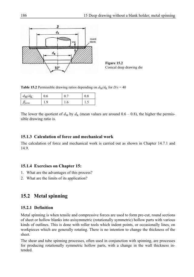
186 15 Deep drawing without a blank holder; metal spinning
Figure 15.2Conical deep drawing die
Table 15.2 Permissible drawing ratios depending on dM/dK for D/s = 40
dM/dK 0.6 0.7 0.8
perm 1.9 1.6 1.5
The lower the quotient of dM by dK (mean values are around 0.6 – 0.8), the higher the permis-sible drawing ratio is.
15.1.3 Calculation of force and mechanical work The calculation of force and mechanical work is carried out as shown in Chapter 14.7.1 and 14.9.
15.1.4 Exercises on Chapter 15: 1. What are the advantages of this process? 2. What are the limits of its application?
15.2 Metal spinning
15.2.1 Definition Metal spinning is when tensile and compressive forces are used to form pre-cut, round sections of sheet or hollow blanks into axisymmetric (rotationally symmetric) hollow parts with various kinds of outlines. This is done with roller tools which indent points, or occasionally lines, on workpieces which are generally rotating. There is no intention to change the thickness of the sheet.The shear and tube spinning processes, often used in conjunction with spinning, are processes for producing rotationally symmetric hollow parts, with a change in the wall thickness in-tended.
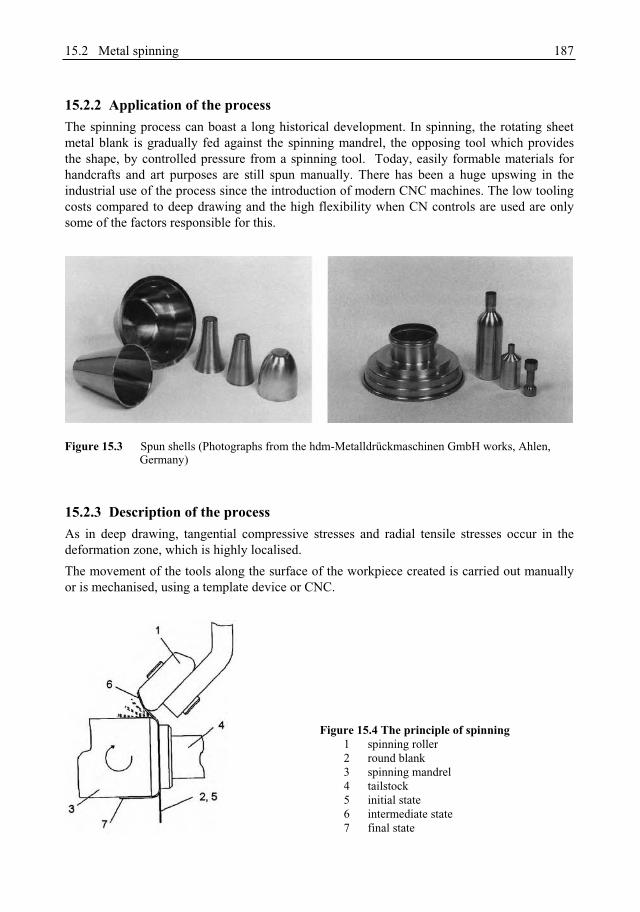
15.2 Metal spinning 187
15.2.2 Application of the process The spinning process can boast a long historical development. In spinning, the rotating sheet metal blank is gradually fed against the spinning mandrel, the opposing tool which provides the shape, by controlled pressure from a spinning tool. Today, easily formable materials for handcrafts and art purposes are still spun manually. There has been a huge upswing in the industrial use of the process since the introduction of modern CNC machines. The low tooling costs compared to deep drawing and the high flexibility when CN controls are used are only some of the factors responsible for this.
Figure 15.3 Spun shells (Photographs from the hdm-Metalldrückmaschinen GmbH works, Ahlen, Germany)
15.2.3 Description of the process As in deep drawing, tangential compressive stresses and radial tensile stresses occur in the deformation zone, which is highly localised. The movement of the tools along the surface of the workpiece created is carried out manually or is mechanised, using a template device or CNC.
Figure 15.4 The principle of spinning 1 spinning roller 2 round blank 3 spinning mandrel 4 tailstock 5 initial state 6 intermediate state 7 final state
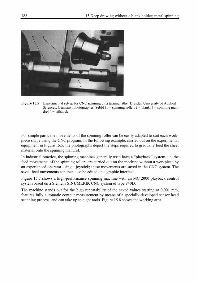
188 15 Deep drawing without a blank holder; metal spinning
Figure 15.5 Experimental set-up for CNC spinning on a turning lathe (Dresden University of Applied Sciences, Germany; photographer: Sebb) (1 spinning roller, 2 blank, 3 spinning man-drel 4 tailstock
For simple parts, the movements of the spinning roller can be easily adapted to suit each work-piece shape using the CNC program. In the following example, carried out on the experimental equipment in Figure 15.5, the photographs depict the steps required to gradually feed the sheet material onto the spinning mandrel. In industrial practice, the spinning machines generally used have a “playback” system, i.e. the feed movements of the spinning rollers are carried out on the machine without a workpiece by an experienced operator using a joystick; these movements are saved in the CNC system. The saved feed movements can then also be edited on a graphic interface. Figure 15.7 shows a high-performance spinning machine with an MC 2000 playback control system based on a Siemens SINUMERIK CNC system of type 840D. The machine stands out for the high repeatability of the saved values starting at 0.001 mm, features fully automatic contour measurement by means of a specially-developed sensor head scanning process, and can take up to eight tools. Figure 15.8 shows the working area.
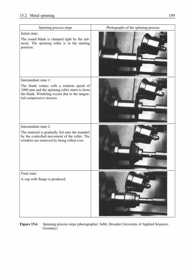
15.2 Metal spinning 189
Spinning process steps Photographs of the spinning process Initial state: The round blank is clamped tight by the tail-stock. The spinning roller is in the starting position.
Intermediate state 1: The blank rotates with a rotation speed of 1000 rpm and the spinning roller starts to form the blank. Wrinkling occurs due to the tangen-tial compressive stresses
Intermediate state 2: The material is gradually fed onto the mandrel by the controlled movement of the roller. The wrinkles are removed by being rolled over.
Final state: A cup with flange is produced.
Figure 15.6 Spinning process steps (photographer: Sebb, Dresden University of Applied Sciences, Germany)
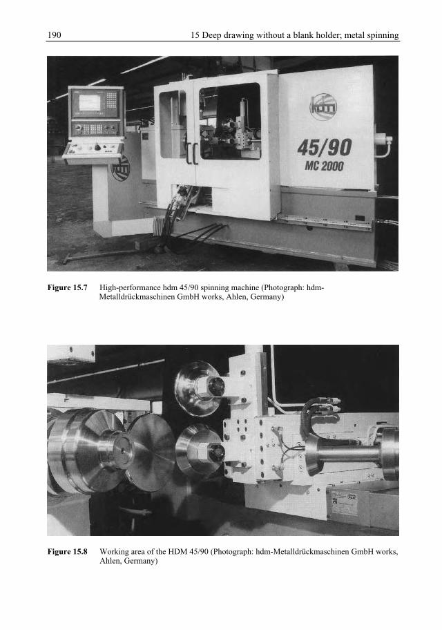
190 15 Deep drawing without a blank holder; metal spinning
Figure 15.7 High-performance hdm 45/90 spinning machine (Photograph: hdm-Metalldrückmaschinen GmbH works, Ahlen, Germany)
Figure 15.8 Working area of the HDM 45/90 (Photograph: hdm-Metalldrückmaschinen GmbH works, Ahlen, Germany)
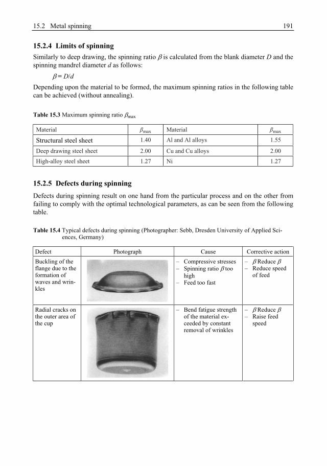
15.2 Metal spinning 191
15.2.4 Limits of spinning Similarly to deep drawing, the spinning ratio is calculated from the blank diameter D and the spinning mandrel diameter d as follows:
= D/dDepending upon the material to be formed, the maximum spinning ratios in the following table can be achieved (without annealing).
Table 15.3 Maximum spinning ratio max
Material max Material max
Structural steel sheet 1.40 Al and Al alloys 1.55
Deep drawing steel sheet 2.00 Cu and Cu alloys 2.00
High-alloy steel sheet 1.27 Ni 1.27
15.2.5 Defects during spinning Defects during spinning result on one hand from the particular process and on the other from failing to comply with the optimal technological parameters, as can be seen from the following table.
Table 15.4 Typical defects during spinning (Photographer: Sebb, Dresden University of Applied Sci-ences, Germany)
Defect Photograph Cause Corrective action Buckling of the flange due to the formation of waves and wrin-kles
– Compressive stresses – Spinning ratio too
high– Feed too fast
– Reduce – Reduce speed
of feed
Radial cracks on the outer area of the cup
– Bend fatigue strength of the material ex-ceeded by constant removal of wrinkles
– Reduce – Raise feed
speed
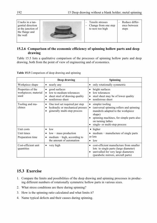
192 15 Deep drawing without a blank holder; metal spinning
Cracks in a tan-gential direction at the junction of the flange and the wall
– Tensile stresses – Change from one step
to next too high
– Reduce differ-ence between steps
15.2.6 Comparison of the economic efficiency of spinning hollow parts and deep drawing
Table 15.5 lists a qualitative comparison of the processes of spinning hollow parts and deep drawing, both from the point of view of engineering and of economics.
Table 15.5 Comparison of deep drawing and spinning
Deep drawing SpinningWorkpiece shape nearly any only rotationally symmetric Properties of the workpieces; material used
good surfaces low to medium tolerances sheet steel of drawing quality nonferrous sheet
bright surfaces low tolerances steel sheet may be of lower quality nonferrous sheet
Tooling and ma-chines
One tool set required per step hydraulic or mechanical presses generally multi-step process
simpler tooling (universal spinning rollers and spinning
mandrels adapted to the workpiece shape)
spinning machines, for simple parts also on turning lathes
single- or multi-step process Unit costs Unit times Preparation time
low low mass production medium high, according to
the amount of automation
higher medium manufacture of single parts
or lots low
Cost-efficient unit quantities
very high cost-efficient manufacture from smaller lots to single parts (large diameter)
unrivalled for very large diameters (parabolic mirrors, aircraft parts)
15.3 Exercise 1. Compare the limits and possibilities of the deep drawing and spinning processes in produc-
ing different numbers of rotationally symmetric hollow parts in various sizes. 2. What stress conditions are there during spinning? 3. How is the spinning ratio calculated and what limits it? 4. Name typical defects and their causes during spinning.
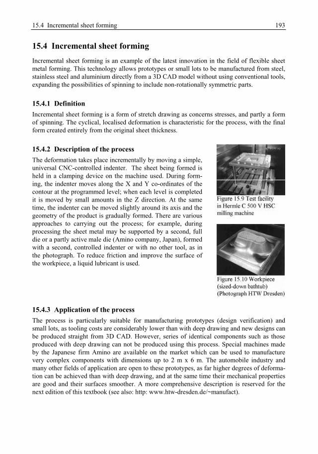
15.4 Incremental sheet forming 193
15.4 Incremental sheet formingIncremental sheet forming is an example of the latest innovation in the field of flexible sheet metal forming. This technology allows prototypes or small lots to be manufactured from steel, stainless steel and aluminium directly from a 3D CAD model without using conventional tools, expanding the possibilities of spinning to include non-rotationally symmetric parts.
15.4.1 DefinitionIncremental sheet forming is a form of stretch drawing as concerns stresses, and partly a form of spinning. The cyclical, localised deformation is characteristic for the process, with the final form created entirely from the original sheet thickness.
15.4.2 Description of the processThe deformation takes place incrementally by moving a simple, universal CNC-controlled indenter. The sheet being formed is held in a clamping device on the machine used. During form-ing, the indenter moves along the X and Y co-ordinates of the contour at the programmed level; when each level is completed it is moved by small amounts in the Z direction. At the same time, the indenter can be moved slightly around its axis and the geometry of the product is gradually formed. There are various approaches to carrying out the process; for example, during processing the sheet metal may be supported by a second, full die or a partly active male die (Amino company, Japan), formed with a second, controlled indenter or with no other tool, as in the photograph. To reduce friction and improve the surface of the workpiece, a liquid lubricant is used.
15.4.3 Application of the processThe process is particularly suitable for manufacturing prototypes (design verification) and small lots, as tooling costs are considerably lower than with deep drawing and new designs can be produced straight from 3D CAD. However, series of identical components such as those produced with deep drawing can not be produced using this process. Special machines made by the Japanese firm Amino are available on the market which can be used to manufacture very complex components with dimensions up to 2 m x 6 m. The automobile industry and many other fields of application are open to these prototypes, as far higher degrees of deforma-tion can be achieved than with deep drawing, and at the same time their mechanical properties are good and their surfaces smoother. A more comprehensive description is reserved for the next edition of this textbook (see also: http: www.htw-dresden.de/~manufact).
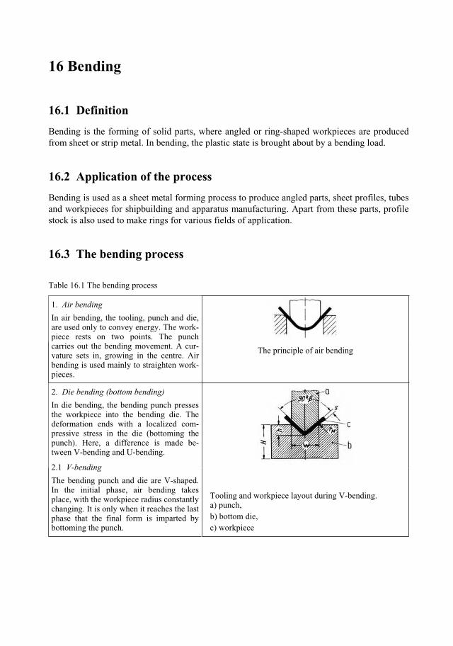
16 Bending
16.1 Definition Bending is the forming of solid parts, where angled or ring-shaped workpieces are produced from sheet or strip metal. In bending, the plastic state is brought about by a bending load.
16.2 Application of the process Bending is used as a sheet metal forming process to produce angled parts, sheet profiles, tubes and workpieces for shipbuilding and apparatus manufacturing. Apart from these parts, profile stock is also used to make rings for various fields of application.
16.3 The bending process
Table 16.1 The bending process
1. Air bendingIn air bending, the tooling, punch and die, are used only to convey energy. The work-piece rests on two points. The punch carries out the bending movement. A cur-vature sets in, growing in the centre. Air bending is used mainly to straighten work-pieces.
The principle of air bending
2. Die bending (bottom bending)In die bending, the bending punch presses the workpiece into the bending die. The deformation ends with a localized com-pressive stress in the die (bottoming the punch). Here, a difference is made be-tween V-bending and U-bending.
2.1 V-bendingThe bending punch and die are V-shaped. In the initial phase, air bending takes place, with the workpiece radius constantly changing. It is only when it reaches the last phase that the final form is imparted by bottoming the punch.
Tooling and workpiece layout during V-bending. a) punch,b) bottom die,c) workpiece
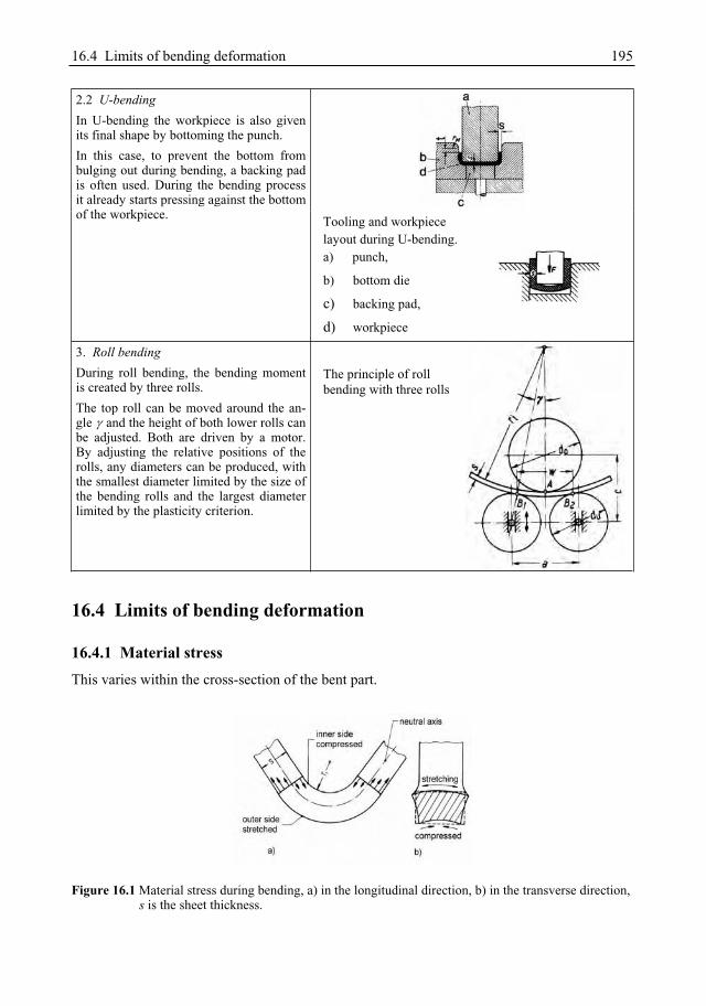
16.4 Limits of bending deformation 195
2.2 U-bendingIn U-bending the workpiece is also given its final shape by bottoming the punch. In this case, to prevent the bottom from bulging out during bending, a backing pad is often used. During the bending process it already starts pressing against the bottom of the workpiece. Tooling and workpiece
layout during U-bending.a) punch,
b) bottom die
c) backing pad,
d) workpiece
3. Roll bendingDuring roll bending, the bending moment is created by three rolls. The top roll can be moved around the an-gle and the height of both lower rolls can be adjusted. Both are driven by a motor. By adjusting the relative positions of the rolls, any diameters can be produced, with the smallest diameter limited by the size of the bending rolls and the largest diameter limited by the plasticity criterion.
The principle of roll bending with three rolls
16.4 Limits of bending deformation
16.4.1 Material stress This varies within the cross-section of the bent part.
Figure 16.1 Material stress during bending, a) in the longitudinal direction, b) in the transverse direction, s is the sheet thickness.
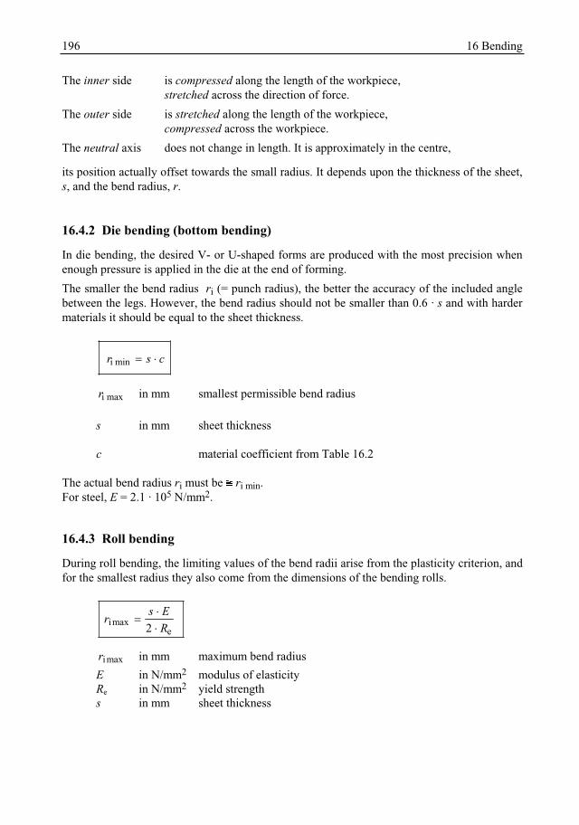
196 16 Bending
The inner side is compressed along the length of the workpiece, stretched across the direction of force.
The outer side is stretched along the length of the workpiece, compressed across the workpiece.
The neutral axis does not change in length. It is approximately in the centre,
its position actually offset towards the small radius. It depends upon the thickness of the sheet, s, and the bend radius, r.
16.4.2 Die bending (bottom bending)
In die bending, the desired V- or U-shaped forms are produced with the most precision when enough pressure is applied in the die at the end of forming. The smaller the bend radius ri (= punch radius), the better the accuracy of the included angle between the legs. However, the bend radius should not be smaller than 0.6 · s and with harder materials it should be equal to the sheet thickness.
i minr s c
i maxr in mm smallest permissible bend radius
s in mm sheet thickness
c material coefficient from Table 16.2
The actual bend radius ri must be ri min.For steel, E = 2.1 · 105 N/mm2.
16.4.3 Roll bending
During roll bending, the limiting values of the bend radii arise from the plasticity criterion, and for the smallest radius they also come from the dimensions of the bending rolls.
imaxe2
s ErR
imaxr in mm maximum bend radius E in N/mm2 modulus of elasticity Re in N/mm2 yield strength s in mm sheet thickness
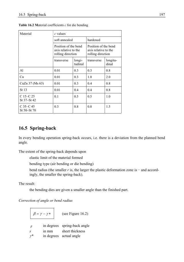
16.5 Spring-back 197
Table 16.2 Material coefficients c for die bending
c values
soft annealed hardened
Position of the bend axis relative to the rolling direction
Position of the bend axis relative to the rolling direction
Material
transverse longi-tudinal
transverse longitu-dinal
Al 0.01 0.3 0.3 0.8
Cu 0.01 0.3 1.0 2.0
CuZn 37 (Ms 63) 0.01 0.3 0.4 0.8
St 13 0.01 0.4 0.4 0.8
C 15–C 25 St 37–St 42
0.1 0.5 0.5 1.0
C 35–C 45 St 50–St 70
0.3 0.8 0.8 1.5
16.5 Spring-back
In every bending operation spring-back occurs, i.e. there is a deviation from the planned bend angle.
The extent of the spring-back depends upon elastic limit of the material formed bending type (air bending or die bending) bend radius (the smaller r is, the larger the plastic deformation zone is and accord-ingly, the smaller the spring-back).
The result: the bending dies are given a smaller angle than the finished part.
Correction of angle or bend radius
(see Figure 16.2)
in degrees spring-back angle s in mm sheet thickness
* in degrees actual angle

198 16 Bending
Figure 16.2 Spring-back of bent parts, a) before, b) after spring-back
Table 16.3 Spring-back angle = f (r1, s) for St up to Rm = 400 N/mm2 and Ms up to Rm = 300 N/mm2
in degrees 5 3 1
s in mm 0.1 to 0.7 0.8 to 1.9 2 to 4
ri in mm 1 · s to 5 · s 1 · s to 5 · s 1 · s to 5 · s
16.6 Determining the blank length L
L = effective length, = the sum of all straight and curved sections
L = l1 + lcu + l2
L in mm effective length Lcu in mm length of the curve l1 in mm length of the leg l2 in mm length of the leg ri in mm bend radius
1 i 2180° 2e sL l r l
s in mm sheet thickness e correction value
in degrees bend angle
for = 90° then L is:
1 i 2 1.57 2
e sL l r l

16.7 Bending force Fb 199
Figure 16.3 Measurements of the bent part for determining blank size
Table 16.4 Correction value e = f (ri/s)
irs
5.0 3.0 2.0 1.2 0.8 0.5
e 1.0 0.9 0.8 0.7 0.6 0.5
The correction value e takes into account the fact that the neutral axis is not exactly in the centre.
16.7 Bending force Fb
16.7.1 Bending in a V-shaped die
2 mb
1.2 b s RFdw
Fb in N bending force w in mm width of the part s in mm thickness of the part Rm in N/mm2 tensile strength dw in mm die width ri in mm bend radius ri min in mm smallest radius still permissible
Figure 16.4 Size and shape of the V-shaped die
6l s
dw = 5 · riif ri ri min 2 · s up to 5 · s
dw = 7 · riif ri = ri min 1.3 · s
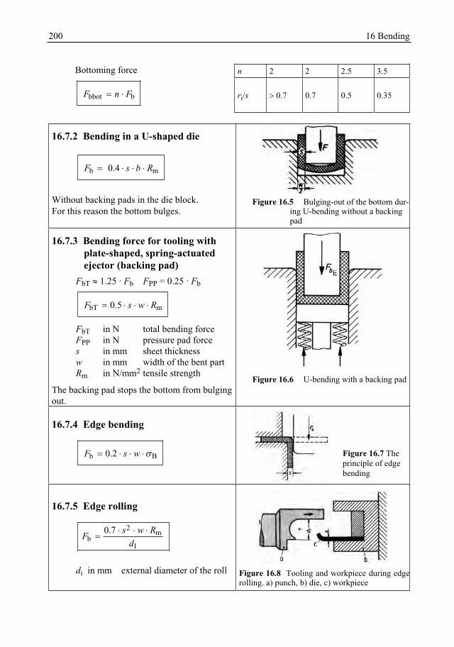
200 16 Bending
n 2 2 2.5 3.5 Bottoming force
bbot bF n F ri/s 0.7 0.7 0.5 0.35
16.7.2 Bending in a U-shaped die
b m 0.4 F s b R
Without backing pads in the die block. For this reason the bottom bulges.
Figure 16.5 Bulging-out of the bottom dur-ing U-bending without a backing pad
16.7.3 Bending force for tooling with plate-shaped, spring-actuated ejector (backing pad)
FbT 1.25 · Fb FPP = 0.25 · Fb
bT m0.5 F s w R
FbT in N total bending force FPP in N pressure pad force s in mm sheet thickness w in mm width of the bent part Rm in N/mm2 tensile strength
The backing pad stops the bottom from bulging out.
Figure 16.6 U-bending with a backing pad
16.7.4 Edge bending
b B0.2 F s w Figure 16.7 Theprinciple of edge bending
16.7.5 Edge rolling
2 mb
1
0.7 s w RFd
di in mm external diameter of the roll Figure 16.8 Tooling and workpiece during edge rolling. a) punch, b) die, c) workpiece
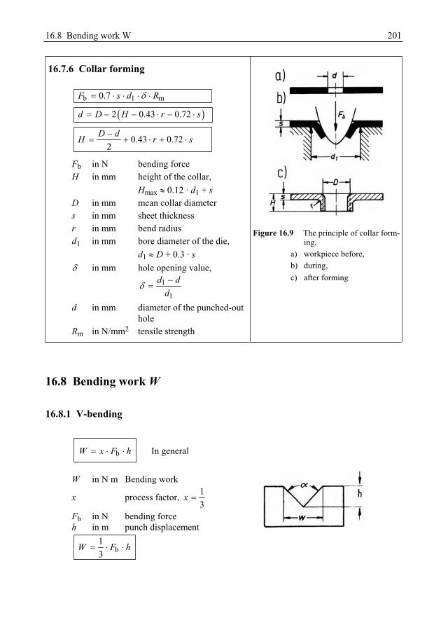
16.8 Bending work W 201
16.7.6 Collar forming
b 1 m 0.7 F s d R
2 0.43 0.72 d D H r s
0.43 0.72 2
D dH r s
Fb in N bending force H in mm height of the collar,
Hmax 0.12 · d1 + sD in mm mean collar diameter s in mm sheet thickness r in mm bend radius d1 in mm bore diameter of the die,
d1 D + 0.3 · s in mm hole opening value,
1
1
d dd
d in mm diameter of the punched-out hole
Rm in N/mm2 tensile strength
Figure 16.9 The principle of collar form-ing,
a) workpiece before, b) during, c) after forming
16.8 Bending work W
16.8.1 V-bending
bW x F h In general
W in N m Bending work
x process factor, 13
x
Fb in N bending force h in m punch displacement
b13
W F h
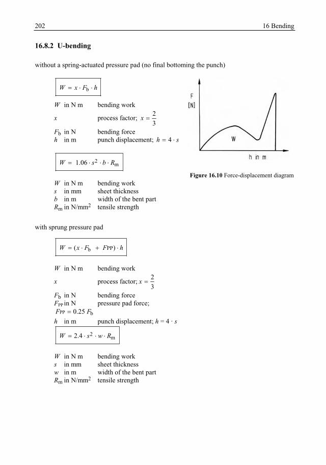
202 16 Bending
16.8.2 U-bending
without a spring-actuated pressure pad (no final bottoming the punch)
bW x F h
W in N m bending work
x process factor; 23
x
Fb in N bending force h in m punch displacement; 4h s
2 m 1.06 W s b R
W in N m bending work s in mm sheet thicknessb in m width of the bent part Rm in N/mm2 tensile strength
with sprung pressure pad
PPb( ) W x F F h
W in N m bending work
x process factor; 23
x
Fb in N bending force FPP in N pressure pad force;
PP b0.25 F Fh in m punch displacement; h = 4 · s
2 m2.4 W s w R
W in N m bending work s in mm sheet thickness w in m width of the bent part Rm in N/mm2 tensile strength
Figure 16.10 Force-displacement diagram
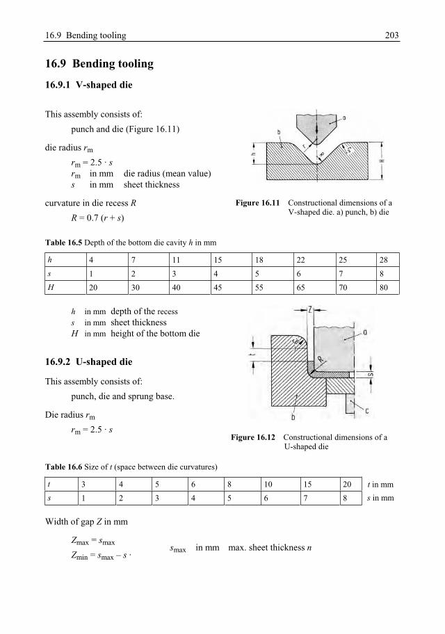
16.9 Bending tooling 203
16.9 Bending tooling
16.9.1 V-shaped die
This assembly consists of: punch and die (Figure 16.11)
die radius rm
rm = 2.5 · srm in mm die radius (mean value) s in mm sheet thickness
curvature in die recess RR = 0.7 (r + s)
Figure 16.11 Constructional dimensions of a V-shaped die. a) punch, b) die
Table 16.5 Depth of the bottom die cavity h in mm
h 4 7 11 15 18 22 25 28s 1 2 3 4 5 6 7 8H 20 30 40 45 55 65 70 80
h in mm depth of the recesss in mm sheet thicknessH in mm height of the bottom die
16.9.2 U-shaped die
This assembly consists of: punch, die and sprung base.
Die radius rm
rm = 2.5 · sFigure 16.12 Constructional dimensions of a
U-shaped die
Table 16.6 Size of t (space between die curvatures)
t 3 4 5 6 8 10 15 20 t in mm s 1 2 3 4 5 6 7 8 s in mm
Width of gap Z in mm
Zmax = smax
Zmin = smax – s ·smax in mm max. sheet thickness n
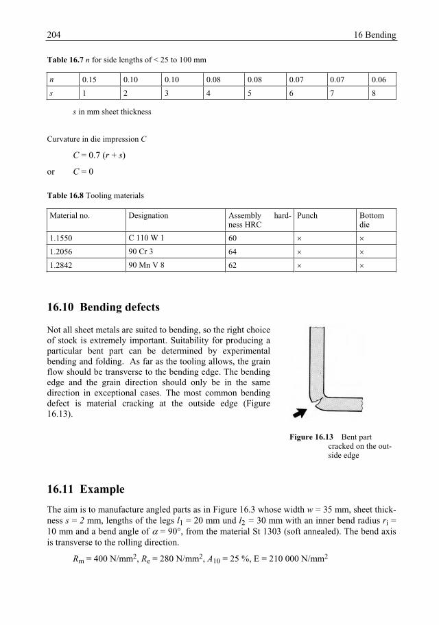
204 16 Bending
Table 16.7 n for side lengths of < 25 to 100 mm
n 0.15 0.10 0.10 0.08 0.08 0.07 0.07 0.06s 1 2 3 4 5 6 7 8
s in mm sheet thickness
Curvature in die impression C
C = 0.7 (r + s)
or C = 0
Table 16.8 Tooling materials
Material no. Designation Assembly hard-ness HRC
Punch Bottom die
1.1550 C 110 W 1 60
1.2056 90 Cr 3 64
1.2842 90 Mn V 8 62
16.10 Bending defects
Not all sheet metals are suited to bending, so the right choice of stock is extremely important. Suitability for producing a particular bent part can be determined by experimental bending and folding. As far as the tooling allows, the grain flow should be transverse to the bending edge. The bending edge and the grain direction should only be in the same direction in exceptional cases. The most common bending defect is material cracking at the outside edge (Figure 16.13).
Figure 16.13 Bent part cracked on the out-side edge
16.11 Example The aim is to manufacture angled parts as in Figure 16.3 whose width w = 35 mm, sheet thick-ness s = 2 mm, lengths of the legs l1 = 20 mm und l2 = 30 mm with an inner bend radius ri = 10 mm and a bend angle of = 90°, from the material St 1303 (soft annealed). The bend axis is transverse to the rolling direction.
Rm = 400 N/mm2, Re = 280 N/mm2, A10 = 25 %, E = 210 000 N/mm2

16.12 Bending machines 205
Find:1. Length of blank 2. Smallest permissible bend radius ri min3. Die width dw4. Bending force 5. Bending work
Solution:
1. 1 i 2180° 2e sL l r l
90° 1 2 mm20 mm 10 mm 30 mm 67.27 mm180° 2
2. ri min = c · s = 0.01 · 2 mm = 0.02 mm c from Table 16.2 ri actual ri min
3. dw = 5 · ri = 5 · 10 mm = 50 mm
4.2 2 2m
b1.2 1.2 35 mm (2 mm) 400 N/mm 1344 N
50 mmw s RF
dw
5. W = x · Fb · h = 13
· 1344 N · 0.025 m = 11.1 N m
50 mm 25 mm2 2
dwh
16.12 Bending machines
Bending machines are sorted according to their fields of application into machines:
1. To produce folded profiles1.1 Press brakes 1.2 Folders (bending brakes)
2. To produce rings and tubes2.1 Three-roll bending machines 2.2 Profile steel bending machines
3. To produce sheet profiles3.1 Beading machines
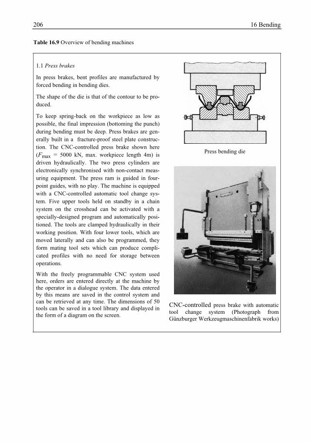
206 16 Bending
Table 16.9 Overview of bending machines
1.1 Press brakes
In press brakes, bent profiles are manufactured by forced bending in bending dies.
The shape of the die is that of the contour to be pro-duced.
To keep spring-back on the workpiece as low as possible, the final impression (bottoming the punch) during bending must be deep. Press brakes are gen-erally built in a fracture-proof steel plate construc-tion. The CNC-controlled press brake shown here (Fmax = 5000 kN, max. workpiece length 4m) is driven hydraulically. The two press cylinders are electronically synchronised with non-contact meas-uring equipment. The press ram is guided in four-point guides, with no play. The machine is equipped with a CNC-controlled automatic tool change sys-tem. Five upper tools held on standby in a chain system on the crosshead can be activated with a specially-designed program and automatically posi-tioned. The tools are clamped hydraulically in their working position. With four lower tools, which are moved laterally and can also be programmed, they form mating tool sets which can produce compli-cated profiles with no need for storage between operations.
With the freely programmable CNC system used here, orders are entered directly at the machine by the operator in a dialogue system. The data entered by this means are saved in the control system and can be retrieved at any time. The dimensions of 50 tools can be saved in a tool library and displayed in the form of a diagram on the screen.
Press bending die
CNC-controlled press brake with automatic tool change system (Photograph from Günzburger Werkzeugmaschinenfabrik works)
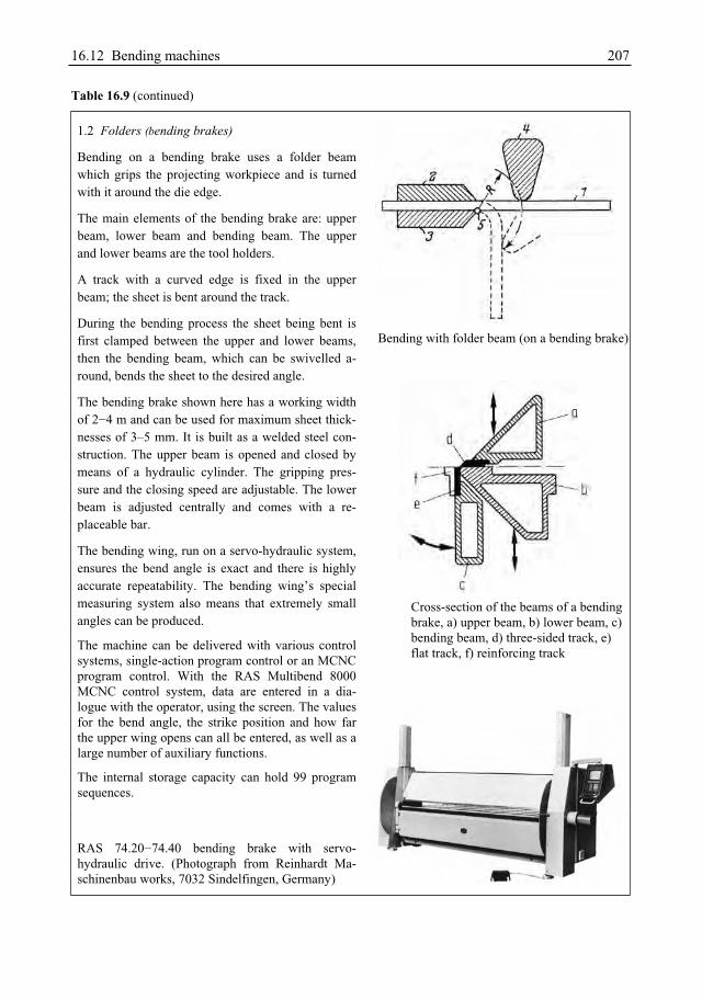
16.12 Bending machines 207
Table 16.9 (continued)
1.2 Folders (bending brakes)
Bending on a bending brake uses a folder beam which grips the projecting workpiece and is turned with it around the die edge.
The main elements of the bending brake are: upper beam, lower beam and bending beam. The upper and lower beams are the tool holders.
A track with a curved edge is fixed in the upper beam; the sheet is bent around the track.
During the bending process the sheet being bent is first clamped between the upper and lower beams, then the bending beam, which can be swivelled a-round, bends the sheet to the desired angle.
The bending brake shown here has a working width of 2 4 m and can be used for maximum sheet thick-nesses of 3–5 mm. It is built as a welded steel con-struction. The upper beam is opened and closed by means of a hydraulic cylinder. The gripping pres-sure and the closing speed are adjustable. The lower beam is adjusted centrally and comes with a re-placeable bar.
The bending wing, run on a servo-hydraulic system, ensures the bend angle is exact and there is highly accurate repeatability. The bending wing’s special measuring system also means that extremely small angles can be produced.
The machine can be delivered with various control systems, single-action program control or an MCNC program control. With the RAS Multibend 8000 MCNC control system, data are entered in a dia-logue with the operator, using the screen. The values for the bend angle, the strike position and how far the upper wing opens can all be entered, as well as a large number of auxiliary functions.
The internal storage capacity can hold 99 program sequences.
RAS 74.20 74.40 bending brake with servo-hydraulic drive. (Photograph from Reinhardt Ma-schinenbau works, 7032 Sindelfingen, Germany)
Bending with folder beam (on a bending brake)
Cross-section of the beams of a bending brake, a) upper beam, b) lower beam, c) bending beam, d) three-sided track, e) flat track, f) reinforcing track
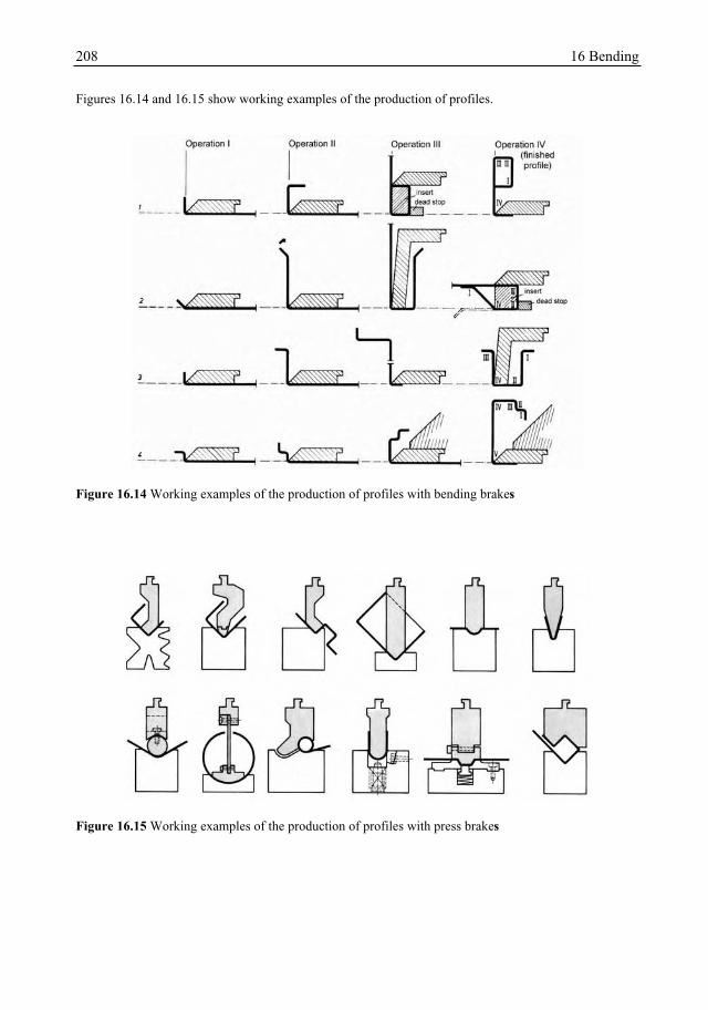
208 16 Bending
Figures 16.14 and 16.15 show working examples of the production of profiles.
Figure 16.14 Working examples of the production of profiles with bending brakes
Figure 16.15 Working examples of the production of profiles with press brakes
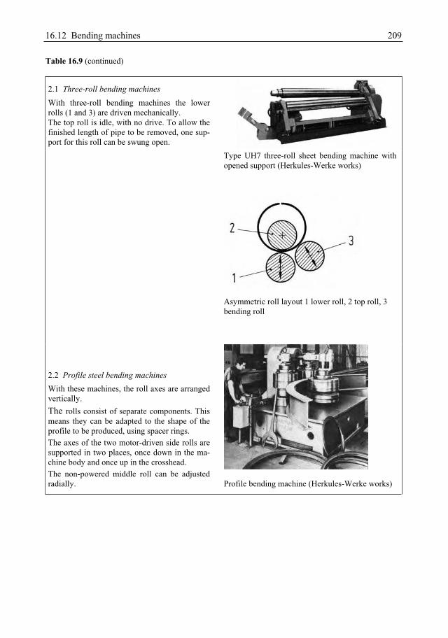
16.12 Bending machines 209
Table 16.9 (continued)
2.1 Three-roll bending machinesWith three-roll bending machines the lower rolls (1 and 3) are driven mechanically. The top roll is idle, with no drive. To allow the finished length of pipe to be removed, one sup-port for this roll can be swung open.
Type UH7 three-roll sheet bending machine with opened support (Herkules-Werke works)
Asymmetric roll layout 1 lower roll, 2 top roll, 3 bending roll
2.2 Profile steel bending machinesWith these machines, the roll axes are arranged vertically.The rolls consist of separate components. This means they can be adapted to the shape of the profile to be produced, using spacer rings.The axes of the two motor-driven side rolls are supported in two places, once down in the ma-chine body and once up in the crosshead.The non-powered middle roll can be adjusted radially. Profile bending machine (Herkules-Werke works)
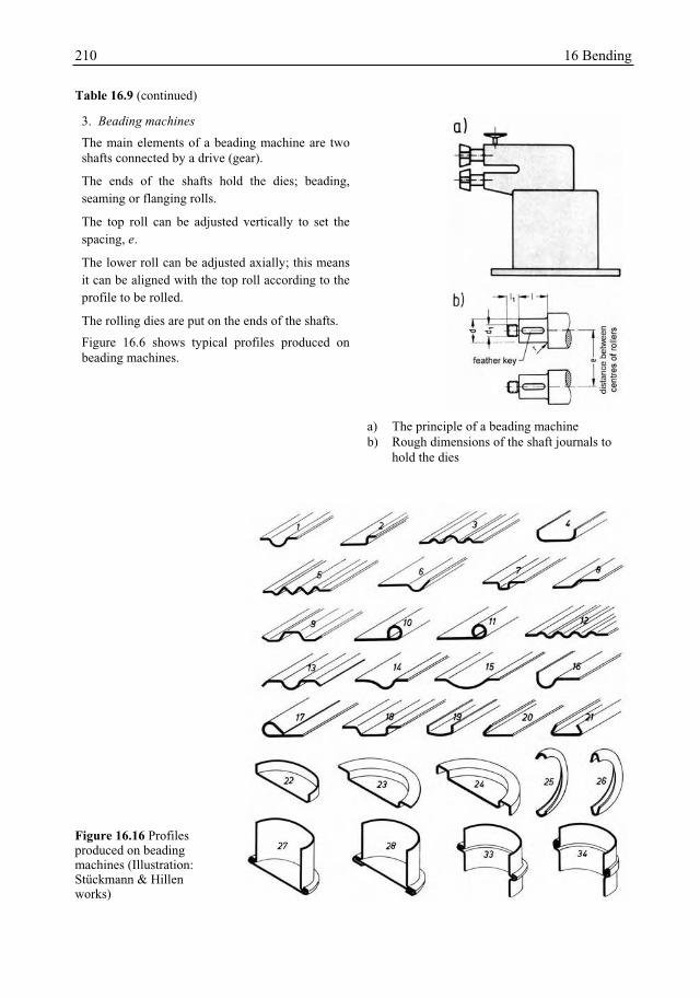
210 16 Bending
Table 16.9 (continued)
3. Beading machinesThe main elements of a beading machine are twoshafts connected by a drive (gear).
The ends of the shafts hold the dies; beading,seaming or flanging rolls.
The top roll can be adjusted vertically to set thespacing, e.
The lower roll can be adjusted axially; this meansit can be aligned with the top roll according to theprofile to be rolled.
The rolling dies are put on the ends of the shafts.
Figure 16.6 shows typical profiles produced onbeading machines.
a) The principle of a beading machineb) Rough dimensions of the shaft journals to
hold the dies
Figure 16.16 Profiles produced on beading machines (Illustration: Stückmann & Hillen works)

16.13 Exercise on Chapter 16 211
16.13 Exercise on Chapter 16
1. What different types of bending process are there? 2. How is the length of the blank determined? 3. What bending machines do you know? 4. Name the three main bending processes. 5. What kinds of workpieces are produced using roll bending? 6. What machines is roll bending carried out on? 7. What are beading machines used for?
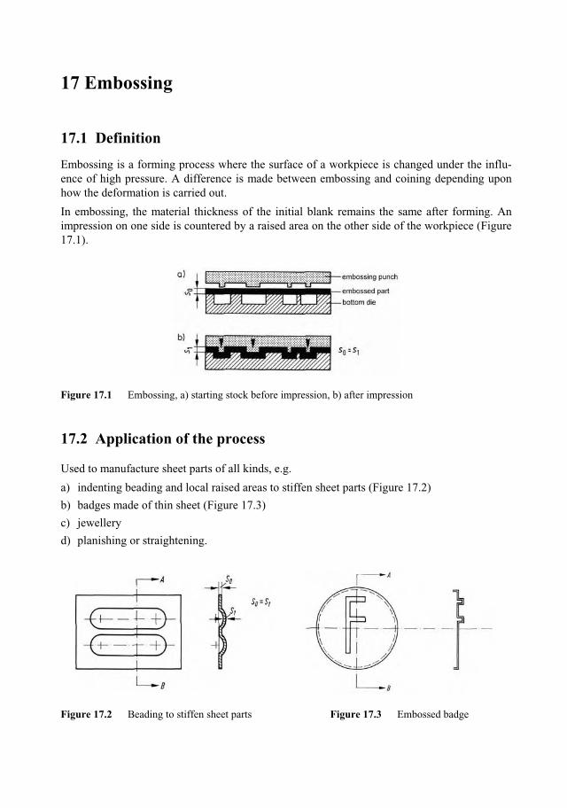
17 Embossing
17.1 Definition Embossing is a forming process where the surface of a workpiece is changed under the influ-ence of high pressure. A difference is made between embossing and coining depending upon how the deformation is carried out. In embossing, the material thickness of the initial blank remains the same after forming. An impression on one side is countered by a raised area on the other side of the workpiece (Figure 17.1).
Figure 17.1 Embossing, a) starting stock before impression, b) after impression
17.2 Application of the process
Used to manufacture sheet parts of all kinds, e.g. a) indenting beading and local raised areas to stiffen sheet parts (Figure 17.2) b) badges made of thin sheet (Figure 17.3) c) jewellery d) planishing or straightening.
Figure 17.2 Beading to stiffen sheet parts Figure 17.3 Embossed badge
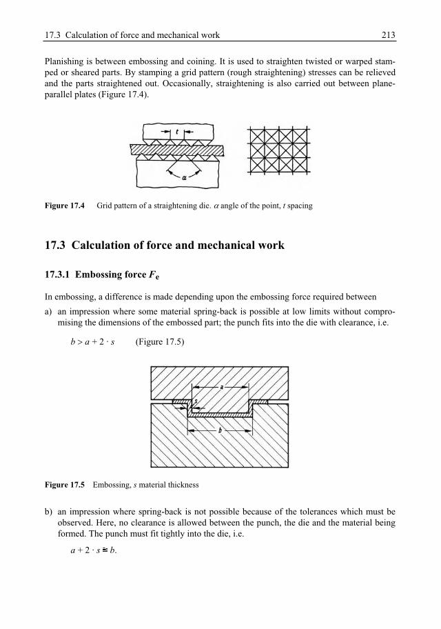
17.3 Calculation of force and mechanical work 213
Planishing is between embossing and coining. It is used to straighten twisted or warped stam-ped or sheared parts. By stamping a grid pattern (rough straightening) stresses can be relieved and the parts straightened out. Occasionally, straightening is also carried out between plane-parallel plates (Figure 17.4).
Figure 17.4 Grid pattern of a straightening die. angle of the point, t spacing
17.3 Calculation of force and mechanical work
17.3.1 Embossing force Fe
In embossing, a difference is made depending upon the embossing force required between a) an impression where some material spring-back is possible at low limits without compro-
mising the dimensions of the embossed part; the punch fits into the die with clearance, i.e.
b a + 2 · s (Figure 17.5)
Figure 17.5 Embossing, s material thickness
b) an impression where spring-back is not possible because of the tolerances which must be observed. Here, no clearance is allowed between the punch, the die and the material being formed. The punch must fit tightly into the die, i.e.
a + 2 · s b.
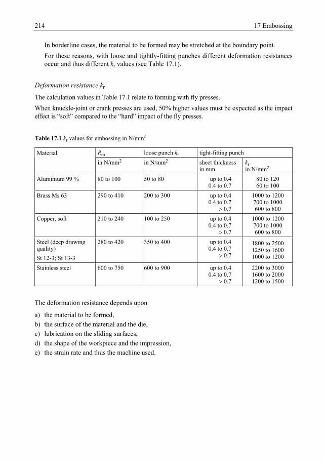
214 17 Embossing
In borderline cases, the material to be formed may be stretched at the boundary point. For these reasons, with loose and tightly-fitting punches different deformation resistances occur and thus different kr values (see Table 17.1).
Deformation resistance kr
The calculation values in Table 17.1 relate to forming with fly presses. When knuckle-joint or crank presses are used, 50% higher values must be expected as the impact effect is “soft” compared to the “hard” impact of the fly presses.
Table 17.1 kr values for embossing in N/mm2
Rm loose punch kr tight-fitting punch Material in N/mm2 in N/mm2 sheet thickness
in mm krin N/mm2
Aluminium 99 % 80 to 100 50 to 80 up to 0.4 0.4 to 0.7
80 to 120 60 to 100
Brass Ms 63 290 to 410 200 to 300 up to 0.4 0.4 to 0.7
0.7
1000 to 1200 700 to 1000 600 to 800
Copper, soft 210 to 240 100 to 250 up to 0.4 0.4 to 0.7
0.7
1000 to 1200 700 to 1000 600 to 800
Steel (deep drawing quality) St 12-3; St 13-3
280 to 420 350 to 400 up to 0.4 0.4 to 0.7
0.7
1800 to 2500 1250 to 1600 1000 to 1200
Stainless steel 600 to 750 600 to 900 up to 0.4 0.4 to 0.7
0.7
2200 to 3000 1600 to 2000 1200 to 1500
The deformation resistance depends upon
a) the material to be formed, b) the surface of the material and the die, c) lubrication on the sliding surfaces, d) the shape of the workpiece and the impression, e) the strain rate and thus the machine used.
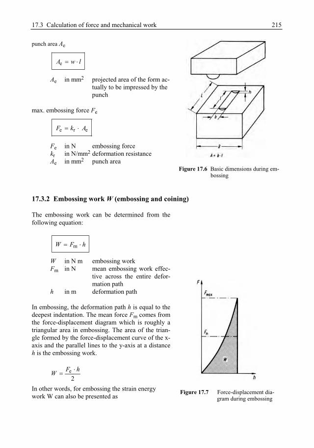
17.3 Calculation of force and mechanical work 215
punch area Ae
eA w l
Ae in mm2 projected area of the form ac-tually to be impressed by the punch
max. embossing force Fe
e r eF k A
Fe in N embossing force kr in N/mm2 deformation resistance Ae in mm2 punch area
Figure 17.6 Basic dimensions during em-bossing
17.3.2 Embossing work W (embossing and coining)
The embossing work can be determined from the following equation:
mW F h
W in N m embossing work Fm in N mean embossing work effec-
tive across the entire defor-mation path
h in m deformation path
In embossing, the deformation path h is equal to the deepest indentation. The mean force Fm comes fromthe force-displacement diagram which is roughly a triangular area in embossing. The area of the trian-gle formed by the force-displacement curve of the x-axis and the parallel lines to the y-axis at a distance h is the embossing work.
e2
F hW
In other words, for embossing the strain energy work W can also be presented as
Figure 17.7 Force-displacement dia-gram during embossing
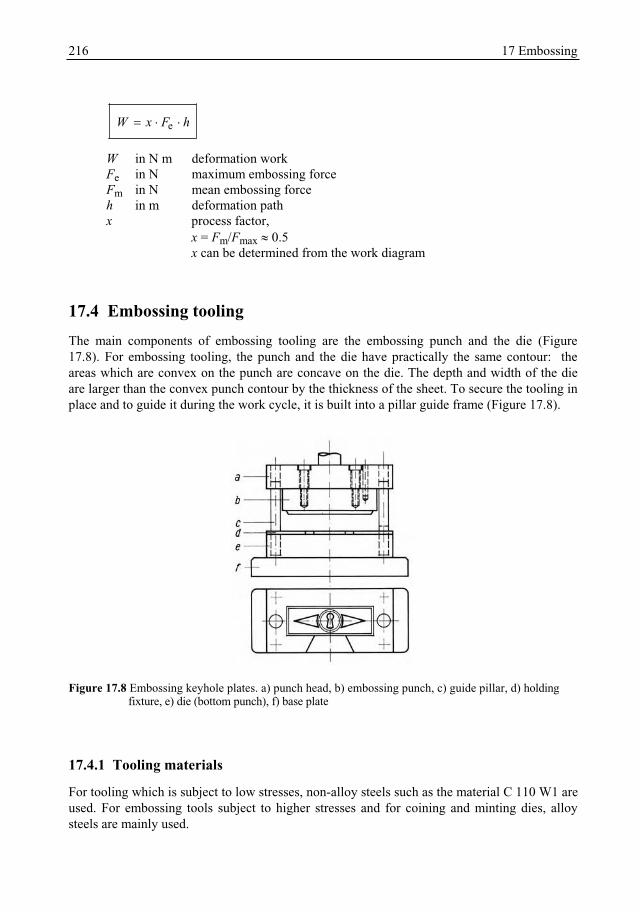
216 17 Embossing
eW x F h
W in N m deformation work Fe in N maximum embossing force Fm in N mean embossing force h in m deformation path x process factor, x = Fm/Fmax 0.5
x can be determined from the work diagram
17.4 Embossing tooling The main components of embossing tooling are the embossing punch and the die (Figure 17.8). For embossing tooling, the punch and the die have practically the same contour: the areas which are convex on the punch are concave on the die. The depth and width of the die are larger than the convex punch contour by the thickness of the sheet. To secure the tooling in place and to guide it during the work cycle, it is built into a pillar guide frame (Figure 17.8).
Figure 17.8 Embossing keyhole plates. a) punch head, b) embossing punch, c) guide pillar, d) holding fixture, e) die (bottom punch), f) base plate
17.4.1 Tooling materials
For tooling which is subject to low stresses, non-alloy steels such as the material C 110 W1 are used. For embossing tools subject to higher stresses and for coining and minting dies, alloy steels are mainly used.
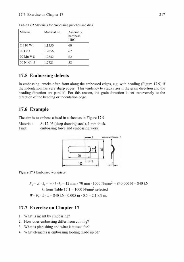
17.7 Exercise on Chapter 17 217
Table 17.2 Materials for embossing punches and dies
Material Material no. Assembly hardnessHRC
C 110 W1 1.1550 6090 Cr 3 1.2056 6290 Mn V 8 1.2842 6250 Ni Cr l3 1.2721 58
17.5 Embossing defects In embossing, cracks often form along the embossed edges, e.g. with beading (Figure 17.9) if the indentation has very sharp edges. This tendency to crack rises if the grain direction and the beading direction are parallel. For this reason, the grain direction is set transversely to the direction of the beading or indentation edge.
17.6 Example The aim is to emboss a bead in a sheet as in Figure 17.9. Material: St 12-03 (deep drawing steel), 1 mm thick. Find: embossing force and embossing work.
Figure 17.9 Embossed workpiece
Fe = A · kr = w · l · kr = 12 mm · 70 mm · 1000 N/mm2 = 840 000 N = 840 kN kr from Table 17.1 = 1000 N/mm2 selected W= Fe · h · x = 840 kN · 0.005 m · 0.5 = 2.1 kN m.
17.7 Exercise on Chapter 17 1. What is meant by embossing? 2. How does embossing differ from coining? 3. What is planishing and what is it used for? 4. What elements is embossing tooling made up of?
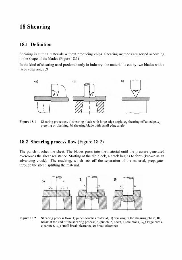
18 Shearing
18.1 Definition
Shearing is cutting materials without producing chips. Shearing methods are sorted according to the shape of the blades (Figure 18.1) In the kind of shearing used predominantly in industry, the material is cut by two blades with a large edge angle .
Figure 18.1 Shearing processes, a) shearing blade with large edge angle: a1 shearing off an edge, a2piercing or blanking, b) shearing blade with small edge angle
18.2 Shearing process flow (Figure 18.2)
The punch touches the sheet. The blades press into the material until the pressure generated overcomes the shear resistance. Starting at the die block, a crack begins to form (known as an advancing crack). The cracking, which sets off the separation of the material, propagates through the sheet, splitting the material.
Figure 18.2 Shearing process flow. I) punch touches material, II) cracking in the shearing phase, III) break at the end of the shearing process, a) punch, b) sheet, c) die block, uL) large break clearance, uS) small break clearance, u) break clearance
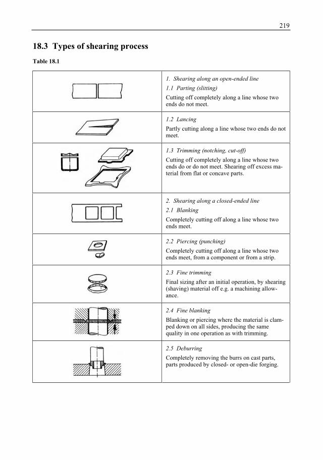
219
18.3 Types of shearing process Table 18.1
1. Shearing along an open-ended line 1.1 Parting (slitting) Cutting off completely along a line whose two ends do not meet.
1.2 Lancing Partly cutting along a line whose two ends do not meet.
1.3 Trimming (notching, cut-off) Cutting off completely along a line whose two ends do or do not meet. Shearing off excess ma-terial from flat or concave parts.
2. Shearing along a closed-ended line 2.1 BlankingCompletely cutting off along a line whose two ends meet.
2.2 Piercing (punching) Completely cutting off along a line whose two ends meet, from a component or from a strip.
2.3 Fine trimming Final sizing after an initial operation, by shearing (shaving) material off e.g. a machining allow-ance.
2.4 Fine blankingBlanking or piercing where the material is clam-ped down on all sides, producing the same quality in one operation as with trimming.
2.5 Deburring Completely removing the burrs on cast parts, parts produced by closed- or open-die forging.

220 18 Shearing
18.4 Permissible deformation The deformation limits arise mainly from the shape of the stamped parts. The shape and ar-rangement of the parts to be produced determine which tools are used and their design.
18.5 Calculation of force and mechanical work
1. Shearing along an open-ended line 1.1 with a straight blade
A w sShearing area
1.2 with an angled blade (e.g. with sheet shears)
2inc
2 2 tanl s sA
2 ; 2 10tan
l to
Shearing area with an angled blade
2. Shearing along a closed-ended line
Shearing area
A C s
Shearing force
BF A
Shearing work
W F s x
The principle of shearing along a closed-ended line

18.5 Calculation of force and mechanical work 221
m
max
FxF
Required machine power
M
F vP
F in N shearing force A in mm2 shearing area s in mm sheet thickness w in mm width l in mm length
B in N/mm2 shear strength in degrees angle of inclination
v in m/s shearing speed
M machine efficiency; M 0.7 W in N m shearing work x process factor, results from force-
displacement diagram; x = 0.6 for shearing
P in W required machine power
Force-displacement diagram
The shear strength B can be roughly calculated mathematically from the tensile strength Rm at:
B mc R
c 0.8 (mean value)
For sheet metals with higher fracture resistance: c = 0.7 For sheet metal with lower fracture resistance and higher failure strain: c = 0.9
Table 18.2 Shear strengths B of various materials
Material Shear strength B in N/mm2
soft hard
St 12 240 300
St 13 240 300
St 14 250 320
St 37 310 –
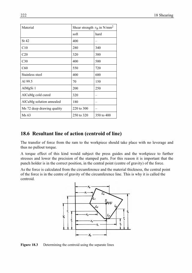
222 18 Shearing
Material Shear strength B in N/mm2
soft hard
St 42 400 –
C10 280 340
C20 320 380
C30 400 500
C60 550 720
Stainless steel 400 600
Al 99.5 70 150
AlMgSi 1 200 250
AlCuMg cold cured 320 –
AlCuMg solution annealed 180 –
Ms 72 deep drawing quality 220 to 300 –
Ms 63 250 to 320 350 to 400
18.6 Resultant line of action (centroid of line) The transfer of force from the ram to the workpiece should take place with no leverage and thus no pullout torque. A torque effect of this kind would subject the press guides and the workpiece to further stresses and lower the precision of the stamped parts. For this reason it is important that the punch holder is in the correct position, in the central point (centre of gravity) of the force. As the force is calculated from the circumference and the material thickness, the central point of the force is in the centre of gravity of the circumference line. This is why it is called the centroid.
Figure 18.3 Determining the centroid using the separate lines

18.6 Resultant line of action (centroid of line) 223
Determining the centroidThe circumference lines are divided into segments with known centroids. Then the product of the segment distances and the segment lengths is found, these products are added together and this sum is divided by the sum of all the segment lengths. For all figures, a circumference line is always made up of the same basic elements. These basic elements are:
circles, arcs and straight lines. The centroids of these basic elements must be known (see Table 18.3).
1 1 2 2 3 3 4 4 5 50
1 2 3 4 5
L x L x L x L x L xxL L L L L
1 1 2 2 3 3 4 4 5 50
1 2 3 4 5
L y L y L y L y L yyL L L L L
L length of the segment xn distance from the ordinates yn distance from the abscissa s (x0/y0) centroid
When piercing symmetric openings, the centroid is not determined from the centroids of the individual lines, but from the circumferences of the symmetrical figures and the centroid of the area.
Example: Where: tooling arranged as in the sketch (Figure 18.4) Find: force centroid
Figure 18.4 Determining the centroid ofthe line when piercing symmetrical openings

224 18 Shearing
Solution:
1. 1 1 2 2 3 3 4 40
1 2 3 4
2
15mm 40mm 37.5mm 50mm 40mm 31.4mm 90 mm 220 mm40mm 50mm 31.4mm 220mm
23531 mm 68.9 mm341.4 mm
x C x C x C x CxC C C C
2. 1 1 2 2 3 3 4 40
1 2 3 4
2
55mm 40 mm 35mm 50mm 15mm 31, 4mm 40mm 220 mm40mm 50mm 31.4mm 220mm
13221mm 38.7 mm341.4mm
y C y C y C y CyC C C C
Table 18.3 Line centroids
Semicircle
0 0.637y r
Quarter circle
0 0.9y r
Any arc
0114.6 sin / 2 2r ry
cu
2 2 sin / 2360
curve length chord length
rcu ch r
cu ch
Straight line
012
y
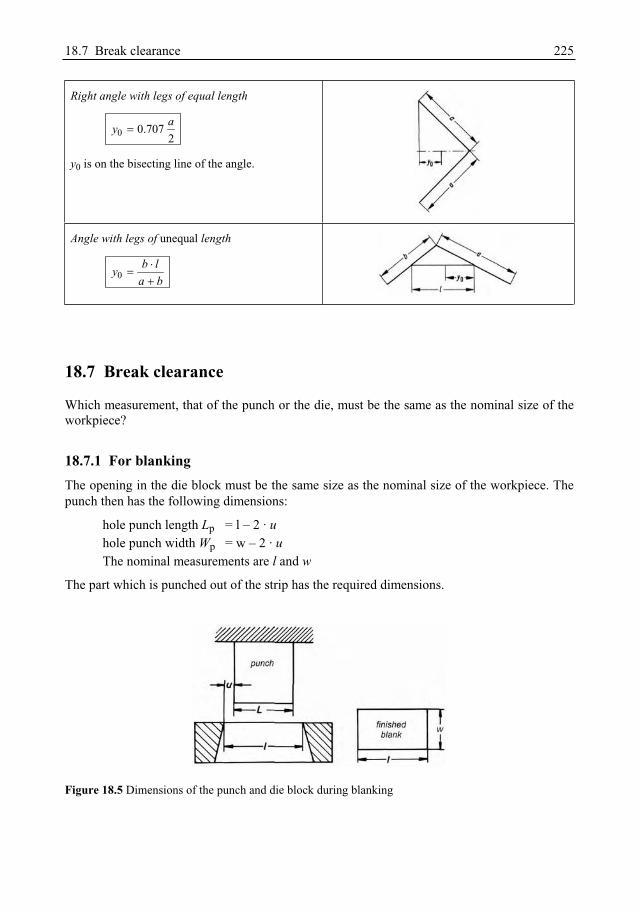
18.7 Break clearance 225
Right angle with legs of equal length
0 0.7072ay
y0 is on the bisecting line of the angle.
Angle with legs of unequal length
0b ly
a b
18.7 Break clearance
Which measurement, that of the punch or the die, must be the same as the nominal size of the workpiece?
18.7.1 For blanking The opening in the die block must be the same size as the nominal size of the workpiece. The punch then has the following dimensions:
hole punch length Lp = l – 2 · uhole punch width Wp = w – 2 · uThe nominal measurements are l and w
The part which is punched out of the strip has the required dimensions.
Figure 18.5 Dimensions of the punch and die block during blanking

226 18 Shearing
18.7.2 For piercing (punching) The punch must be the same size as the nominal size of the workpiece. Here, the diameter of the die measures:
d = nominal size D = d + 2 · u
The hole has the required dimensions.
Figure 18.6 Dimensions of the punch and the die block during punching
18.7.3 Size of the break clearance uFor thin sheet up to 3 mm thick (empirical equation)
2 B0.007 mm /u N s
u in mm break clearance s in mm sheet thickness
B in N/mm2 shear strength
For sheet > 3 mm thick
2 B(0.007 0.005mm) mm /u s N
punch clearance c
2c u
c in mm punch clearance
The break clearance influences the cleanness of the sheared surface, the shearing force and the shearing work. With thinner sheet steels (< 2.5 mm), the proportion of the fracture surface is higher when the break clearance is larger. Too narrow break clearances, less than u = 0.1 · s, lead to earing.
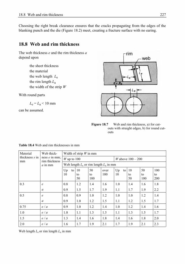
18.8 Web and rim thickness 227
Choosing the right break clearance ensures that the cracks propagating from the edges of the blanking punch and the die (Figure 18.2) meet, creating a fracture surface with no earing.
18.8 Web and rim thickness The web thickness e and the rim thickness adepend upon
the sheet thickness the material the web length Lethe rim length Lathe width of the strip W
With round parts
Le = La < 10 mm
can be assumed.
Figure 18.7 Web and rim thickness, a) for cut-outs with straight edges, b) for round cut-outs
Table 18.4 Web and rim thicknesses in mm
Width of strip W in mm W up to 100 W above 100 – 200 Web length Le or rim length La in mm
Material thickness s in mm
Web thick-ness e in mm; rim thickness a in mm
Up to10
10to50
50to100
over100
Up to10
10to50
50to100
100to200
0.3 ea
0.80.9
1.21.5
1.41.7
1.61.9
1.01.1
1.41.7
1.61.9
1.82.2
0.5 ea
0.80.9
0.91.0
1.01.2
1.21.5
1.01.1
1.01.2
1.21.5
1.41.7
0.75 e / a 0.9 1.0 1.2 1.4 1.0 1.2 1.4 1.6
1.0 e / a 1.0 1.1 1.3 1.5 1.1 1.3 1.5 1.7
1.5 e / a 1.3 1.4 1.6 1.8 1.4 1.6 1.8 2.0
2.0 e / a 1.6 1.7 1.9 2.1 1.7 1.9 2.1 2.3
Web length Le or rim length La in mm

228 18 Shearing
18.9 Achievable precision Tables 18.5, 18.6 and 18.7 show the tolerances which can be met when piercing or blanking. When piercing openings, higher precision can generally be achieved than with blanking. The values in the table can be halved when higher precision is required by using especially pre-cisely-manufactured tooling. By additional trimming, the tolerances in Tables 18.5 and 18.6 can be reduced to one fifth of the values in the tables.
Table 18.5 Tolerances in mm when piercing openings
Size of the opening in mm Material thickness s in mm
up to 10 11 to 30 31 to 50 51 to 100
0.3 to 1.0 0.05 0.07 0.08 0.12
1 to 2 0.06 0.08 0.10 0.14
2 to 4 0.08 0.10 0.12 0.15
Table 18.6 Tolerances in mm when blanking
Max. side length of the cut-out in mm Material thickness s in mm
up to 10 11 to 30 31 to 50 51 to 100 101 to 200
0.3 to 1.0 0.10 0.14 0.16 0.20 0.25
1 to 2 0.18 0.20 0.22 0.28 0.40
2 to 4 0.24 0.26 0.28 0.34 0.60
Table 18.7 Tolerances in mm for the distance between the centres of the openings
Distance between the centres in mm Material thickness s in mm
up to 50 51 to 100 101 to 200
0.3 to 1.0 ± 0.1 ± 0.15 ± 0.20
1 to 2 ± 0.12 ± 0.20 ± 0.25
2 to 4 ± 0.15 ± 0.25 ± 0.30
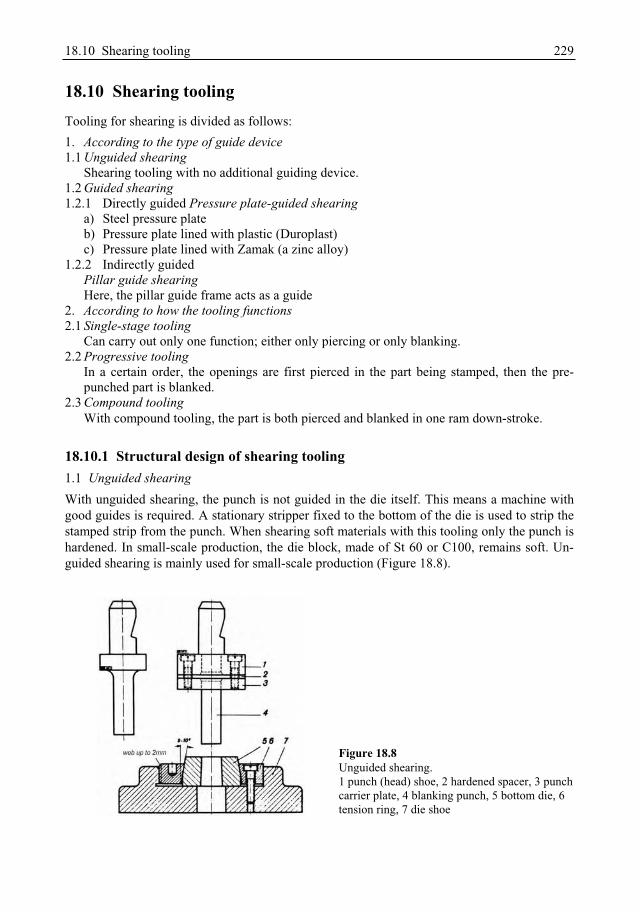
18.10 Shearing tooling 229
18.10 Shearing tooling Tooling for shearing is divided as follows: 1. According to the type of guide device1.1 Unguided shearing
Shearing tooling with no additional guiding device. 1.2 Guided shearing1.2.1 Directly guided Pressure plate-guided shearing
a) Steel pressure plate b) Pressure plate lined with plastic (Duroplast) c) Pressure plate lined with Zamak (a zinc alloy)
1.2.2 Indirectly guided Pillar guide shearingHere, the pillar guide frame acts as a guide
2. According to how the tooling functions2.1 Single-stage tooling
Can carry out only one function; either only piercing or only blanking. 2.2 Progressive tooling
In a certain order, the openings are first pierced in the part being stamped, then the pre-punched part is blanked.
2.3 Compound toolingWith compound tooling, the part is both pierced and blanked in one ram down-stroke.
18.10.1 Structural design of shearing tooling 1.1 Unguided shearingWith unguided shearing, the punch is not guided in the die itself. This means a machine with good guides is required. A stationary stripper fixed to the bottom of the die is used to strip the stamped strip from the punch. When shearing soft materials with this tooling only the punch is hardened. In small-scale production, the die block, made of St 60 or C100, remains soft. Un-guided shearing is mainly used for small-scale production (Figure 18.8).
Figure 18.8 Unguided shearing.1 punch (head) shoe, 2 hardened spacer, 3 punch carrier plate, 4 blanking punch, 5 bottom die, 6 tension ring, 7 die shoe
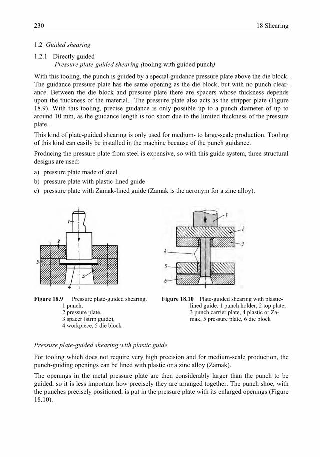
230 18 Shearing
1.2 Guided shearing
1.2.1 Directly guided Pressure plate-guided shearing (tooling with guided punch)
With this tooling, the punch is guided by a special guidance pressure plate above the die block. The guidance pressure plate has the same opening as the die block, but with no punch clear-ance. Between the die block and pressure plate there are spacers whose thickness depends upon the thickness of the material. The pressure plate also acts as the stripper plate (Figure 18.9). With this tooling, precise guidance is only possible up to a punch diameter of up to around 10 mm, as the guidance length is too short due to the limited thickness of the pressure plate.This kind of plate-guided shearing is only used for medium- to large-scale production. Tooling of this kind can easily be installed in the machine because of the punch guidance. Producing the pressure plate from steel is expensive, so with this guide system, three structural designs are used: a) pressure plate made of steel b) pressure plate with plastic-lined guide c) pressure plate with Zamak-lined guide (Zamak is the acronym for a zinc alloy).
Figure 18.9 Pressure plate-guided shearing. 1 punch,2 pressure plate, 3 spacer (strip guide), 4 workpiece, 5 die block
Figure 18.10 Plate-guided shearing with plastic-lined guide. 1 punch holder, 2 top plate, 3 punch carrier plate, 4 plastic or Za-mak, 5 pressure plate, 6 die block
Pressure plate-guided shearing with plastic guide
For tooling which does not require very high precision and for medium-scale production, the punch-guiding openings can be lined with plastic or a zinc alloy (Zamak). The openings in the metal pressure plate are then considerably larger than the punch to be guided, so it is less important how precisely they are arranged together. The punch shoe, with the punches precisely positioned, is put in the pressure plate with its enlarged openings (Figure 18.10).
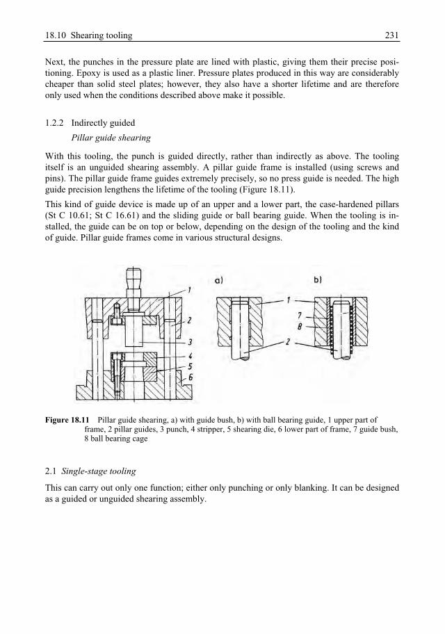
18.10 Shearing tooling 231
Next, the punches in the pressure plate are lined with plastic, giving them their precise posi-tioning. Epoxy is used as a plastic liner. Pressure plates produced in this way are considerably cheaper than solid steel plates; however, they also have a shorter lifetime and are therefore only used when the conditions described above make it possible.
1.2.2 Indirectly guided Pillar guide shearing
With this tooling, the punch is guided directly, rather than indirectly as above. The tooling itself is an unguided shearing assembly. A pillar guide frame is installed (using screws and pins). The pillar guide frame guides extremely precisely, so no press guide is needed. The high guide precision lengthens the lifetime of the tooling (Figure 18.11). This kind of guide device is made up of an upper and a lower part, the case-hardened pillars (St C 10.61; St C 16.61) and the sliding guide or ball bearing guide. When the tooling is in-stalled, the guide can be on top or below, depending on the design of the tooling and the kind of guide. Pillar guide frames come in various structural designs.
Figure 18.11 Pillar guide shearing, a) with guide bush, b) with ball bearing guide, 1 upper part of frame, 2 pillar guides, 3 punch, 4 stripper, 5 shearing die, 6 lower part of frame, 7 guide bush, 8 ball bearing cage
2.1 Single-stage tooling
This can carry out only one function; either only punching or only blanking. It can be designed as a guided or unguided shearing assembly.
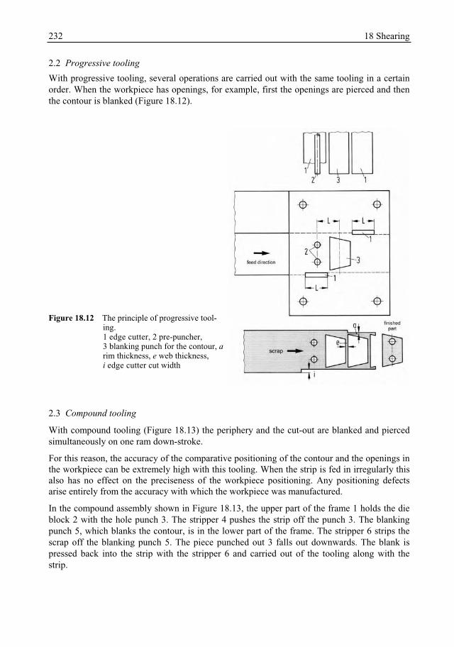
232 18 Shearing
2.2 Progressive toolingWith progressive tooling, several operations are carried out with the same tooling in a certain order. When the workpiece has openings, for example, first the openings are pierced and then the contour is blanked (Figure 18.12).
Figure 18.12 The principle of progressive tool-ing.1 edge cutter, 2 pre-puncher, 3 blanking punch for the contour, arim thickness, e web thickness,i edge cutter cut width
2.3 Compound tooling
With compound tooling (Figure 18.13) the periphery and the cut-out are blanked and pierced simultaneously on one ram down-stroke.
For this reason, the accuracy of the comparative positioning of the contour and the openings in the workpiece can be extremely high with this tooling. When the strip is fed in irregularly this also has no effect on the preciseness of the workpiece positioning. Any positioning defects arise entirely from the accuracy with which the workpiece was manufactured.
In the compound assembly shown in Figure 18.13, the upper part of the frame 1 holds the die block 2 with the hole punch 3. The stripper 4 pushes the strip off the punch 3. The blanking punch 5, which blanks the contour, is in the lower part of the frame. The stripper 6 strips the scrap off the blanking punch 5. The piece punched out 3 falls out downwards. The blank is pressed back into the strip with the stripper 6 and carried out of the tooling along with the strip.
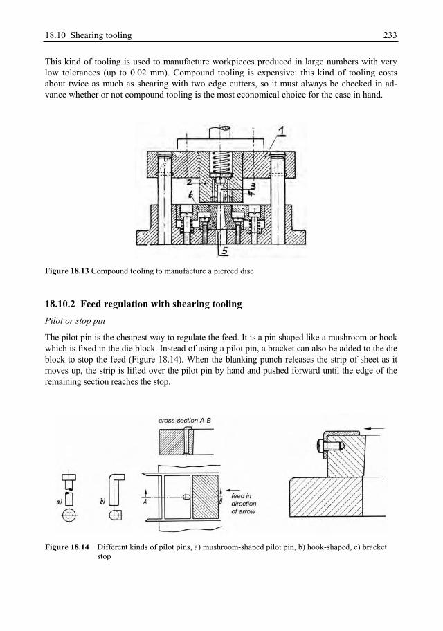
18.10 Shearing tooling 233
This kind of tooling is used to manufacture workpieces produced in large numbers with very low tolerances (up to 0.02 mm). Compound tooling is expensive: this kind of tooling costs about twice as much as shearing with two edge cutters, so it must always be checked in ad-vance whether or not compound tooling is the most economical choice for the case in hand.
Figure 18.13 Compound tooling to manufacture a pierced disc
18.10.2 Feed regulation with shearing tooling Pilot or stop pin
The pilot pin is the cheapest way to regulate the feed. It is a pin shaped like a mushroom or hook which is fixed in the die block. Instead of using a pilot pin, a bracket can also be added to the die block to stop the feed (Figure 18.14). When the blanking punch releases the strip of sheet as it moves up, the strip is lifted over the pilot pin by hand and pushed forward until the edge of the remaining section reaches the stop.
Figure 18.14 Different kinds of pilot pins, a) mushroom-shaped pilot pin, b) hook-shaped, c) bracket stop
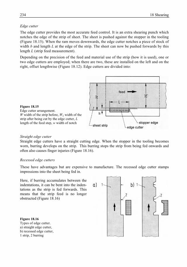
234 18 Shearing
Edge cutterThe edge cutter provides the most accurate feed control. It is an extra shearing punch which notches the edge of the strip of sheet. The sheet is pushed against the stopper in the tooling (Figure 18.15). When the ram moves downwards, the edge cutter notches a piece of stock of width b and length L at the edge of the strip. The sheet can now be pushed forwards by this length L (strip feed measurement). Depending on the precision of the feed and material use of the strip (how it is used), one or two edge cutters are employed; when there are two, these are installed on the left and on the right, offset lengthwise (Figure 18.12). Edge cutters are divided into:
Figure 18.15 Edge cutter arrangement.W width of the strip before, W1 width of the strip after being cut by the edge cutter, Llength of the feed step, w width of notch
Straight edge cutter Straight edge cutters have a straight cutting edge. When the stopper in the tooling becomes worn, burring develops on the strip. This burring stops the strip from being fed onwards and often also causes finger injuries (Figure 18.16).
Recessed edge cutters
These have advantages but are expensive to manufacture. The recessed edge cutter stamps impressions into the sheet being fed in.
Here, if burring accumulates between the indentations, it can be bent into the inden-tations as the strip is fed forwards. This means that the strip feed is no longer obstructed (Figure 18.16)
Figure 18.16 Types of edge cutter. a) straight edge cutter, b) recessed edge cutter, 1 strip, 2 burring
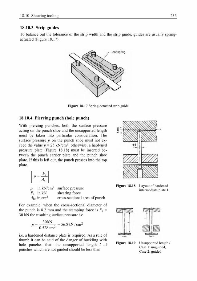
18.10 Shearing tooling 235
18.10.3 Strip guides To balance out the tolerance of the strip width and the strip guide, guides are usually spring-actuated (Figure 18.17).
Figure 18.17 Spring-actuated strip guide
18.10.4 Piercing punch (hole punch) With piercing punches, both the surface pressure acting on the punch shoe and the unsupported length must be taken into particular consideration. The surface pressure p on the punch shoe must not ex-ceed the value p = 25 kN/cm2; otherwise, a hardened pressure plate (Figure 18.18) must be inserted be-tween the punch carrier plate and the punch shoe plate. If this is left out, the punch presses into the top plate.
s
k
FpA
p in kN/cm2 surface pressure Fs in kN shearing force Ahd in cm2 cross-sectional area of punch
For example, when the cross-sectional diameter ofthe punch is 8.2 mm and the stamping force is Fs =30 kN the resulting surface pressure is:
22
30kN 56.8kN / cm0.528cm
p
i.e. a hardened distance plate is required. As a rule ofthumb it can be said of the danger of buckling with hole punches that: the unsupported length l ofpunches which are not guided should be less than
Figure 18.18 Layout of hardened intermediate plate 1
Figure 18.19 Unsupported length lCase 1: unguided, Case 2: guided
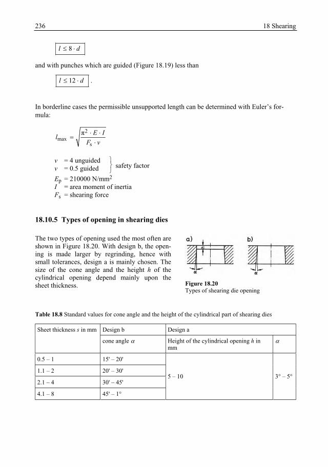
236 18 Shearing
8l d
and with punches which are guided (Figure 18.19) less than
12l d .
In borderline cases the permissible unsupported length can be determined with Euler’s for-mula:
2max
s
E IlF v
v = 4 unguidedv = 0.5 guided safety factor
Ep = 210000 N/mm2
I = area moment of inertia Fs = shearing force
18.10.5 Types of opening in shearing dies
The two types of opening used the most often are shown in Figure 18.20. With design b, the open-ing is made larger by regrinding, hence with small tolerances, design a is mainly chosen. The size of the cone angle and the height h of the cylindrical opening depend mainly upon the sheet thickness. Figure 18.20
Types of shearing die opening
Table 18.8 Standard values for cone angle and the height of the cylindrical part of shearing dies
Design b Design a Sheet thickness s in mm
cone angle Height of the cylindrical opening h in mm
0.5 – 1 15' – 20'
1.1 – 2 20' – 30'
2.1 – 4 30' – 45'
4.1 – 8 45' – 1°
5 – 10 3° – 5°
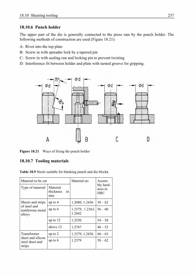
18.10 Shearing tooling 237
18.10.6 Punch holder The upper part of the die is generally connected to the press ram by the punch holder. The following methods of construction are used (Figure 18.21):
A: Rivet into the top plate B: Screw in with spreader lock by a tapered pin C: Screw in with sealing run and locking pin to prevent twisting D: Interference fit between holder and plate with turned groove for gripping.
Figure 18.21 Ways of fixing the punch holder
18.10.7 Tooling materials
Table 18.9 Steels suitable for blanking punch and die blocks
Material to be cut
Type of material Material thickness in mm
Material no. Assem-bly hard-ness in HRC
up to 4 1.2080, 1.2436 58 – 62
up to 6 1.2379, 1.2363, 1.2842
56 – 60
up to 12 1.2550 54 – 58
Sheets and strips of steel and nonferrous metal alloys
above 12 1.2767 48 – 52
up to 2 1.2379, 1.2436 60 – 63 Transformer sheet and silicon steel sheet and strips
up to 6 1.2379 58 – 62
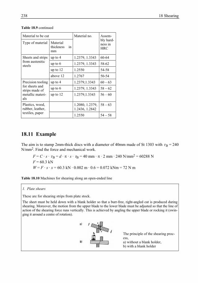
238 18 Shearing
Table 18.9 continued
Material to be cut
Type of material Material thickness in mm
Material no. Assem-bly hard-ness in HRC
up to 4 1.2379, 1.3343 60-64 up to 6 1.2379, 1.3343 58-62 up to 12 1.2550 54-58
Sheets and strips from austenitic steels
above 12 1.2767 50-54 up to 4 1.2379,1.3343 60 – 63 up to 6 1.2379, 1.3343 58 – 62
Precision tooling for sheets and strips made of metallic materi-als
up to 12 1.2379,1.3343 56 – 60
1.2080, 1.2379, 1.2436, 1.2842
58 – 63 Plastics, wood, rubber, leather, textiles, paper 1.2550 54 – 58
18.11 Example
The aim is to stamp 2mm-thick discs with a diameter of 40mm made of St 1303 with B = 240 N/mm2. Find the force and mechanical work.
F = C · s · B = d · · s · B = 40 mm · · 2 mm · 240 N/mm2 = 60288 N F = 60.3 kN W = F · s · x = 60.3 kN · 0.002 m · 0.6 = 0.072 kNm = 72 N m
Table 18.10 Machines for shearing along an open-ended line
1. Plate shears
These are for shearing strips from plate stock. The sheet must be held down with a blank holder so that a burr-free, right-angled cut is produced during shearing. Moreover, the motion from the upper blade to the lower blade must be adjusted so that the line of action of the shearing force runs vertically. This is achieved by angling the upper blade or rocking it (swin-ging it around a centre of rotation).
The principle of the shearing proc-ess, a) without a blank holder,b) with a blank holder
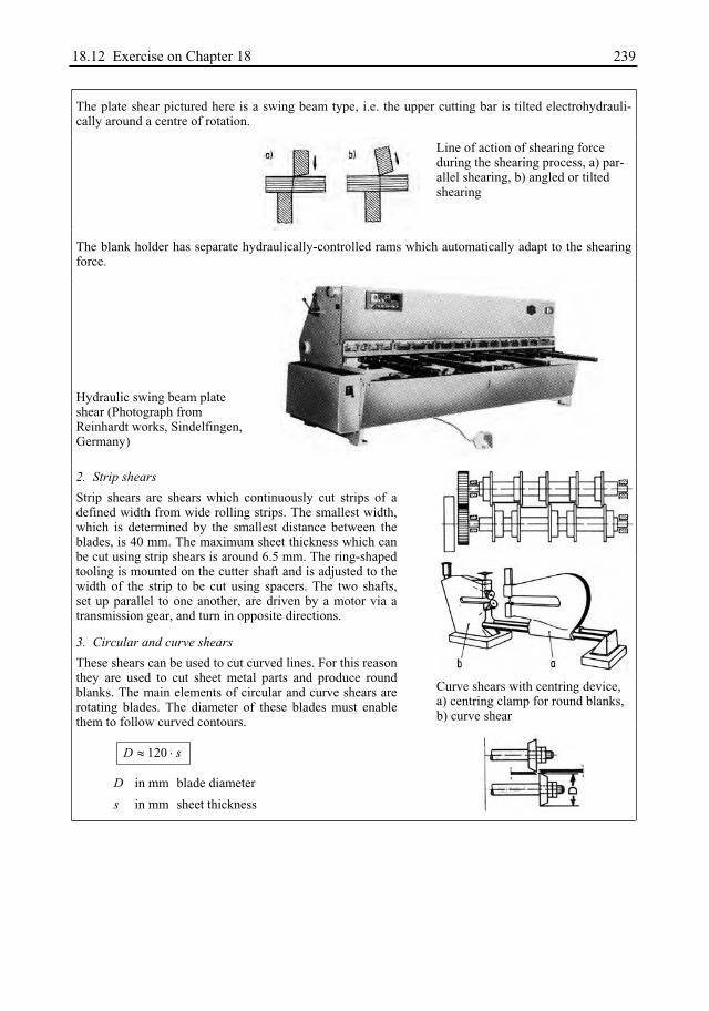
18.12 Exercise on Chapter 18 239
The plate shear pictured here is a swing beam type, i.e. the upper cutting bar is tilted electrohydrauli-cally around a centre of rotation.
Line of action of shearing force during the shearing process, a) par-allel shearing, b) angled or tilted shearing
The blank holder has separate hydraulically-controlled rams which automatically adapt to the shearing force.
Hydraulic swing beam plate shear (Photograph fromReinhardt works, Sindelfingen, Germany)
Curve shears with centring device, a) centring clamp for round blanks, b) curve shear
2. Strip shears Strip shears are shears which continuously cut strips of a defined width from wide rolling strips. The smallest width, which is determined by the smallest distance between the blades, is 40 mm. The maximum sheet thickness which can be cut using strip shears is around 6.5 mm. The ring-shaped tooling is mounted on the cutter shaft and is adjusted to the width of the strip to be cut using spacers. The two shafts, set up parallel to one another, are driven by a motor via a transmission gear, and turn in opposite directions.
3. Circular and curve shears These shears can be used to cut curved lines. For this reason they are used to cut sheet metal parts and produce round blanks. The main elements of circular and curve shears are rotating blades. The diameter of these blades must enable them to follow curved contours.
120D s
D in mm blade diameter s in mm sheet thickness

240 18 Shearing
18.12 Exercise on Chapter 18
1. What are the different types of shearing process? 2. Describe the different phases of the shearing process. 3. Why is the movable upper blade of sheet cutting shears tilted towards the table area? 4. In shearing assemblies, why must the punch holder be in the centroid of the blanking
punch? 5. What is meant by “break clearance”, “web thickness” and “rim thickness”? 6. What kinds of shearing tooling are there? 7. What is progressive tooling and what stamped parts is it used for? 8. How does compound shearing tooling work? 9. What is an edge cutter and what is its function? 10. Why is a recessed edge cutter better than a straight edge cutter? 11. What must be taken into consideration for guiding the strip? 12. Why must the blanking punch not be too long? 13. What are the following needed for: a plate shear
a strip shear a circular shear?
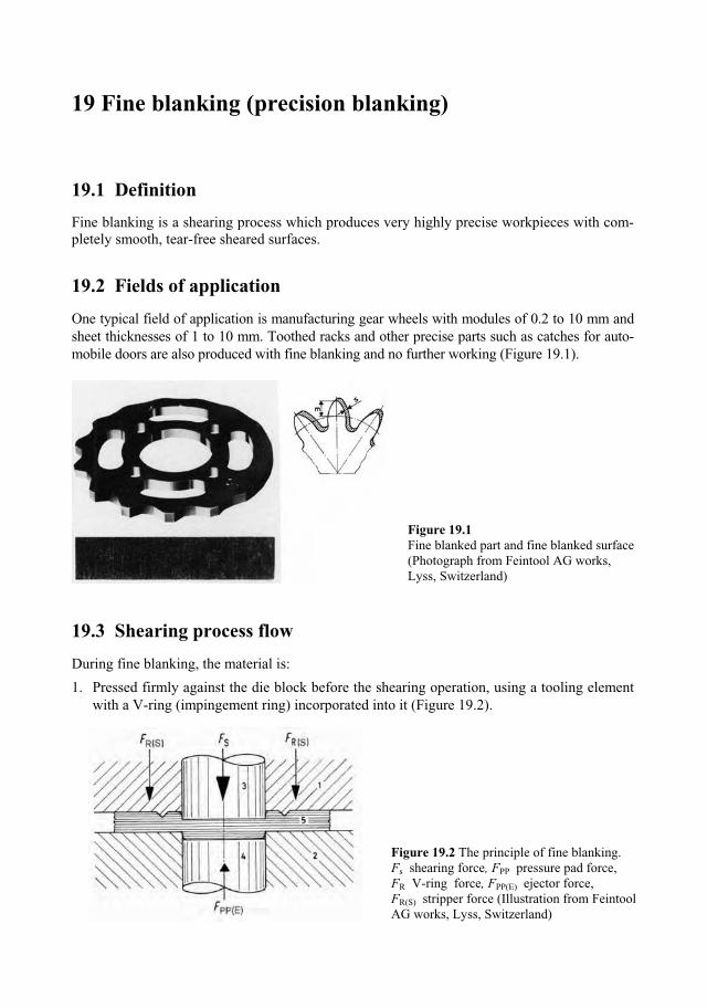
19 Fine blanking (precision blanking)
19.1 Definition Fine blanking is a shearing process which produces very highly precise workpieces with com-pletely smooth, tear-free sheared surfaces.
19.2 Fields of application One typical field of application is manufacturing gear wheels with modules of 0.2 to 10 mm and sheet thicknesses of 1 to 10 mm. Toothed racks and other precise parts such as catches for auto-mobile doors are also produced with fine blanking and no further working (Figure 19.1).
Figure 19.1 Fine blanked part and fine blanked surface (Photograph from Feintool AG works, Lyss, Switzerland)
19.3 Shearing process flow During fine blanking, the material is: 1. Pressed firmly against the die block before the shearing operation, using a tooling element
with a V-ring (impingement ring) incorporated into it (Figure 19.2).
Figure 19.2 The principle of fine blanking. Fs shearing force, FPP pressure pad force,FR V-ring force, FPP(E) ejector force,FR(S) stripper force (Illustration from Feintool AG works, Lyss, Switzerland)
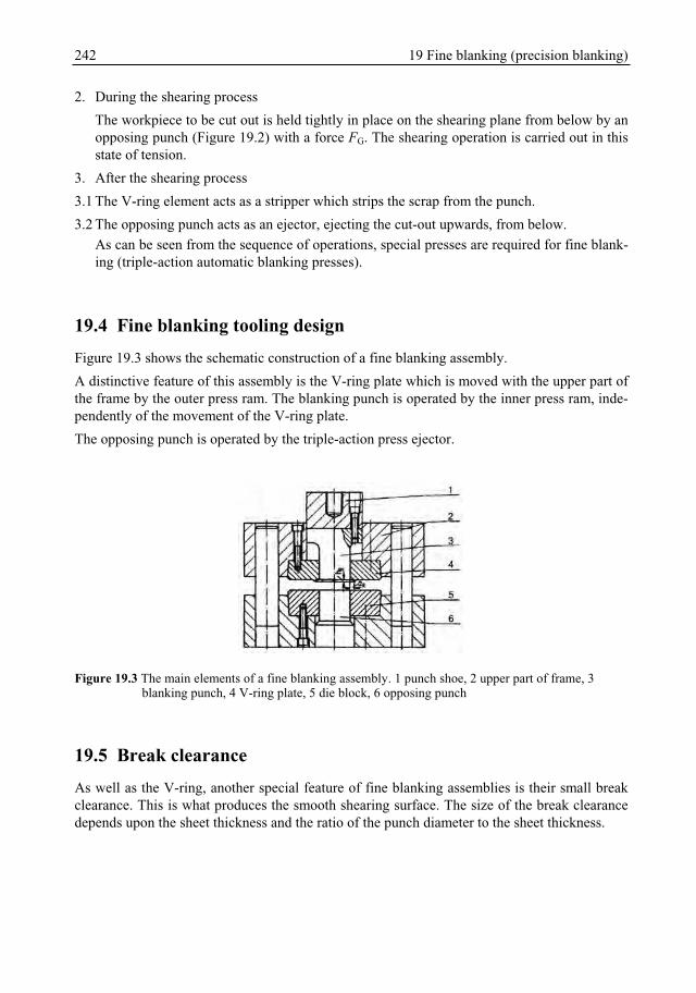
242 19 Fine blanking (precision blanking)
2. During the shearing process The workpiece to be cut out is held tightly in place on the shearing plane from below by an opposing punch (Figure 19.2) with a force FG. The shearing operation is carried out in this state of tension.
3. After the shearing process 3.1 The V-ring element acts as a stripper which strips the scrap from the punch. 3.2 The opposing punch acts as an ejector, ejecting the cut-out upwards, from below.
As can be seen from the sequence of operations, special presses are required for fine blank-ing (triple-action automatic blanking presses).
19.4 Fine blanking tooling design Figure 19.3 shows the schematic construction of a fine blanking assembly. A distinctive feature of this assembly is the V-ring plate which is moved with the upper part of the frame by the outer press ram. The blanking punch is operated by the inner press ram, inde-pendently of the movement of the V-ring plate. The opposing punch is operated by the triple-action press ejector.
Figure 19.3 The main elements of a fine blanking assembly. 1 punch shoe, 2 upper part of frame, 3 blanking punch, 4 V-ring plate, 5 die block, 6 opposing punch
19.5 Break clearance As well as the V-ring, another special feature of fine blanking assemblies is their small break clearance. This is what produces the smooth shearing surface. The size of the break clearance depends upon the sheet thickness and the ratio of the punch diameter to the sheet thickness.

19.6 Forces during fine blanking 243
Table 19.1 Break clearance u subject to the sheet thickness s and the punch diameter to sheet thickness ratio d/s
s in mm 1 2 3 4 5 8
u in mm for q = 0.7 0.012 0.024 0.036 0.048 0.06 0.095
u in mm for q = 1.0 0.01 0.02 0.03 0.04 0.05 0.08
u in mm for q = 1.2 0.005 0.01 0.015 0.02 0.025 0.04
;dqs
d in mm punch diameter, s in mm sheet thickness
19.6 Forces during fine blanking
Shearing force
s B · · F C s
Fs in N shearing force C in mm circumference of the blanking punch s in mm sheet thickness
B in N/mm2 shear strength (see Table 18.2 Chapter 18.5).
V-ring force (Figure 19.4)
R m4F L h R
L in mm length of the V-ring h in mm V-ring height (Figure 19.4) Rm in N/mm2 tensile strength FR in N V-ring force
Figure 19.4 Shape of the V-ring
Table 19.2 V-ring height h subject to the sheet thickness s
h in mm 0.3 0.5 0.7 0.8 1.0
s in mm 1 – 2 2.1 – 3 3.1 – 6 6.1 – 9 9.1 – 11
244 19 Fine blanking (precision blanking)
Opposing force
oppF A p
p = 20 N/mm2 to 70 N/mm2
p = 20 for thin parts with a small area Fopp in N opposing force A in mm2 area of the fine-blanked part (top view of the part being blanked) p in N/mm2 specific contact pressure
Stripper force or ejector force
E s0.12F F
FE in N stripper force / ejector force
The V-ring plate strips the scrap from the blanking punch (stripper force) and the opposing punch pushes the part out of the die block (ejector force).
19.7 Fine blanking presses
Fine blanking presses are triple-action mechanically-driven presses with up to 2500 kN press force or hydraulically-driven presses with up to 14000 kN press force. These CNC-controlled machines have a ram which operates vertically from below to above; the se-quence of movements is regulated with a precise upper ram reversal point; the ram is pre-cisely guided and the columns are very rigid.
Feintool mechanical fine blanking presses (Figure 19.5) are driven by a fully variable DC motor via the flywheel, a multi-plate clutch and a worm gear on two synchronously-running crankshafts of different eccentricity. These crankshafts drive a double knuckle-joint system which produces the controlled sequence of movements.
Feintool hydraulic fine blanking presses (Figure 19.6) are fitted with an accumulator drive. The hydraulic pump continually charges a high-pressure accumulator, storing energy something like the flywheel of a mechanical fine blanking press. During the shearing proc-ess, this accumulator powers the main ram cylinder. This means that unlike a direct drive, the shearing speed does not depend upon the pump capacity. At the same time, the hydraulic pump also powers the low-pressure accumulator which powers the high-speed closing cyl-inder. As a result, each phase of the movement can be tailored to any kind of tooling de-pending upon the path, the pressure and the speed. At the end of the shearing process, the ram comes up against a mechanically adjustable positive stop at the upper reversal point.
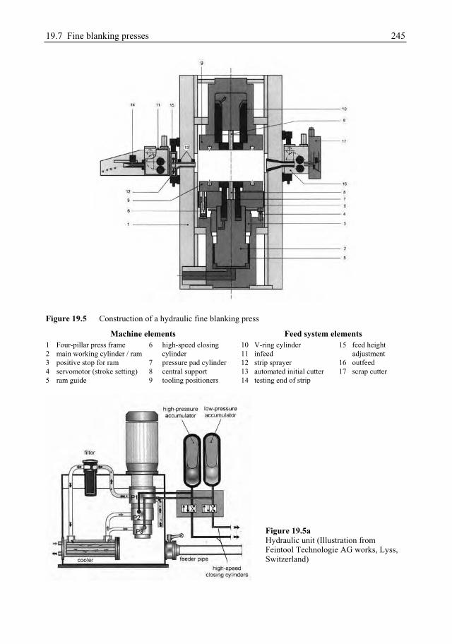
19.7 Fine blanking presses 245
Figure 19.5 Construction of a hydraulic fine blanking press
Machine elements Feed system elements1 Four-pillar press frame 2 main working cylinder / ram 3 positive stop for ram 4 servomotor (stroke setting) 5 ram guide
6 high-speed closing cylinder
7 pressure pad cylinder 8 central support 9 tooling positioners
10 V-ring cylinder 11 infeed 12 strip sprayer 13 automated initial cutter 14 testing end of strip
15 feed height adjustment
16 outfeed 17 scrap cutter
Figure 19.5a Hydraulic unit (Illustration from Feintool Technologie AG works, Lyss, Switzerland)
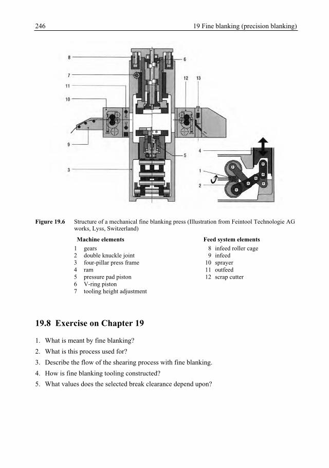
246 19 Fine blanking (precision blanking)
Figure 19.6 Structure of a mechanical fine blanking press (Illustration from Feintool Technologie AG works, Lyss, Switzerland)
Machine elements Feed system elements 1 gears 2 double knuckle joint 3 four-pillar press frame 4 ram 5 pressure pad piston 6 V-ring piston 7 tooling height adjustment
8 infeed roller cage 9 infeed 10 sprayer 11 outfeed 12 scrap cutter
19.8 Exercise on Chapter 19
1. What is meant by fine blanking? 2. What is this process used for? 3. Describe the flow of the shearing process with fine blanking. 4. How is fine blanking tooling constructed? 5. What values does the selected break clearance depend upon?
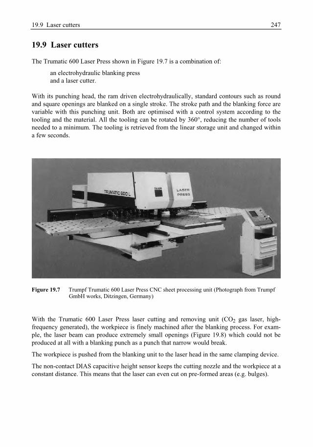
19.9 Laser cutters 247
19.9 Laser cutters
The Trumatic 600 Laser Press shown in Figure 19.7 is a combination of:
an electrohydraulic blanking press and a laser cutter.
With its punching head, the ram driven electrohydraulically, standard contours such as round and square openings are blanked on a single stroke. The stroke path and the blanking force are variable with this punching unit. Both are optimised with a control system according to the tooling and the material. All the tooling can be rotated by 360°, reducing the number of tools needed to a minimum. The tooling is retrieved from the linear storage unit and changed within a few seconds.
Figure 19.7 Trumpf Trumatic 600 Laser Press CNC sheet processing unit (Photograph from Trumpf GmbH works, Ditzingen, Germany)
With the Trumatic 600 Laser Press laser cutting and removing unit (CO2 gas laser, high-frequency generated), the workpiece is finely machined after the blanking process. For exam-ple, the laser beam can produce extremely small openings (Figure 19.8) which could not be produced at all with a blanking punch as a punch that narrow would break.
The workpiece is pushed from the blanking unit to the laser head in the same clamping device.
The non-contact DIAS capacitive height sensor keeps the cutting nozzle and the workpiece at a constant distance. This means that the laser can even cut on pre-formed areas (e.g. bulges).
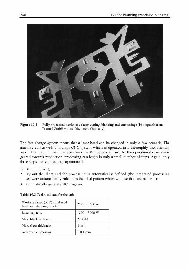
248 19 Fine blanking (precision blanking)
Figure 19.8 Fully processed workpiece (laser cutting, blanking and embossing) (Photograph from Trumpf GmbH works, Ditzingen, Germany)
The fast change system means that a laser head can be changed in only a few seconds. The machine comes with a Trumpf CNC system which is operated in a thoroughly user-friendly way. The graphic user interface meets the Windows standard. As the operational structure is geared towards production, processing can begin in only a small number of steps. Again, only three steps are required to programme it:
1. read in drawing; 2. lay out the sheet and the processing is automatically defined (the integrated processing
software automatically calculates the ideal pattern which will use the least material); 3. automatically generate NC program.
Table 19.3 Technical data for the unit
Working range (X,Y) combined laser and blanking function 2585 1600 mm
Laser capacity 1800 – 3000 W
Max. blanking force 220 kN
Max. sheet thickness 8 mm
Achievable precision + 0.1 mm
20 Joining by forming
Joining by forming includes all processes where parts being joined or involved in the join-ing are formed locally, sometimes also completely. The deformation forces may be gener-ated mechanically, electromagnetically or in another way e.g. by an explosion. Generally, the joint is kept from unintentionally coming undone by positive locking. With joining, a difference is made between
– forming wire-shaped bodies (e.g. braiding)
– forming sheet, tube and profiled parts (flanging, bending, clinching) and
– riveting processes (hollow riveting, punch riveting).
This chapter deals with clinching and punch riveting with no pre-punching, as these methods have been growing in importance since the mid-1990s. The advantages they confer in automo-bile production mean that they can largely replace conventional resistance spot welding.
Their economic advantages are in the joinability of differing materials (e.g. aluminium with steel), the longer tooling life and avoiding heat input. With higher-strength sheet in particular, the latter means that better use can be made of its strength, as the original properties of the material are not changed thermally.
At the point of joining, the deformation is carried out by deliberately changing the thickness of the semi-finished product. This is a bulk forming operation made up of different, overlapping processes, e.g. pushing through, compressing, extrusion.
Difficulties still arise when calculating theoretical values such as the required force and work, or describing process limits (joinable sheet thicknesses, joinable strengths) due to the complex triaxial changes in the states of tension and deformation involved. For this reason, until now development has been shaped by experiments. In future, the increasing use of numerical simu-lation will reduce the number of experiments needed.
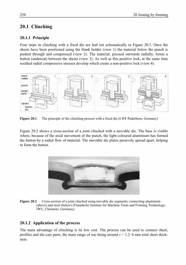
250 20 Joining by forming
20.1 Clinching
20.1.1 Principle Four steps in clinching with a fixed die are laid out schematically in Figure 20.1. Once the sheets have been positioned using the blank holder (view 1) the material below the punch is pushed through and compressed (view 2). The material, pressed outwards radially, forms a button (undercut) between the sheets (view 3). As well as this positive lock, at the same time residual radial compressive stresses develop which create a non-positive lock (view 4).
Figure 20.1 The principle of the clinching process with a fixed die (LWF Paderborn, Germany)
Figure 20.2 shows a cross-section of a joint clinched with a movable die. The base is visible where, because of the axial movement of the punch, the light-coloured aluminium has formed the button by a radial flow of material. The movable die plates passively spread apart, helping to form the button.
Figure 20.2 Cross-section of a joint clinched using movable die segments; connecting aluminium (above) and steel (below) (Fraunhofer Institute for Machine Tools and Forming Technology, IWU, Chemnitz, Germany)
20.1.2 Application of the process The main advantage of clinching is its low cost. The process can be used to connect sheet, profiles and die-cast parts, the main range of use being around s = 1.2–4 mm total sheet thick-ness.
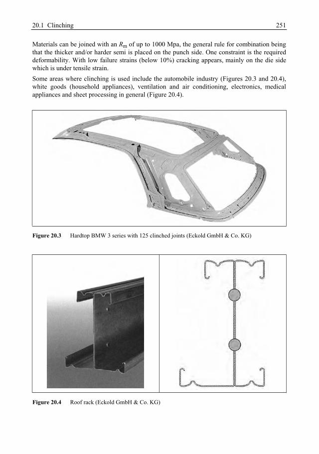
20.1 Clinching 251
Materials can be joined with an Rm of up to 1000 Mpa, the general rule for combination being that the thicker and/or harder semi is placed on the punch side. One constraint is the required deformability. With low failure strains (below 10%) cracking appears, mainly on the die side which is under tensile strain. Some areas where clinching is used include the automobile industry (Figures 20.3 and 20.4), white goods (household appliances), ventilation and air conditioning, electronics, medical appliances and sheet processing in general (Figure 20.4).
Figure 20.3 Hardtop BMW 3 series with 125 clinched joints (Eckold GmbH & Co. KG)
Figure 20.4 Roof rack (Eckold GmbH & Co. KG)
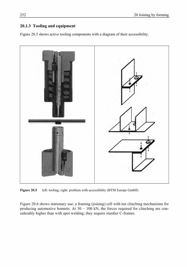
252 20 Joining by forming
20.1.3 Tooling and equipment
Figure 20.5 shows active tooling components with a diagram of their accessibility.
Figure 20.5 left: tooling; right: problem with accessibility (BTM Europe GmbH)
Figure 20.6 shows stationary use; a framing (joining) cell with ten clinching mechanisms for producing automotive bonnets. At 30 100 kN, the forces required for clinching are con-siderably higher than with spot welding; they require sturdier C-frames.
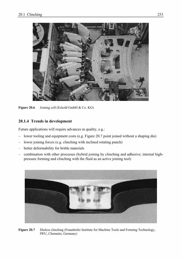
20.1 Clinching 253
Figure 20.6 Joining cell (Eckold GmbH & Co. KG)
20.1.4 Trends in development
Future applications will require advances in quality, e.g.:
– lower tooling and equipment costs (e.g. Figure 20.7 point joined without a shaping die) – lower joining forces (e.g. clinching with inclined rotating punch) – better deformability for brittle materials – combination with other processes (hybrid joining by clinching and adhesive; internal high-
pressure forming and clinching with the fluid as an active joining tool)
Figure 20.7 Dieless clinching (Fraunhofer Institute for Machine Tools and Forming Technology, IWU, Chemnitz, Germany)
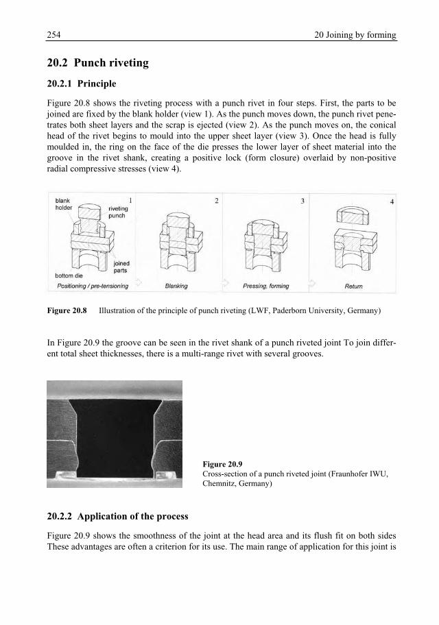
254 20 Joining by forming
20.2 Punch riveting
20.2.1 Principle
Figure 20.8 shows the riveting process with a punch rivet in four steps. First, the parts to be joined are fixed by the blank holder (view 1). As the punch moves down, the punch rivet pene-trates both sheet layers and the scrap is ejected (view 2). As the punch moves on, the conical head of the rivet begins to mould into the upper sheet layer (view 3). Once the head is fully moulded in, the ring on the face of the die presses the lower layer of sheet material into the groove in the rivet shank, creating a positive lock (form closure) overlaid by non-positive radial compressive stresses (view 4).
Figure 20.8 Illustration of the principle of punch riveting (LWF, Paderborn University, Germany)
In Figure 20.9 the groove can be seen in the rivet shank of a punch riveted joint To join differ-ent total sheet thicknesses, there is a multi-range rivet with several grooves.
Figure 20.9Cross-section of a punch riveted joint (Fraunhofer IWU, Chemnitz, Germany)
20.2.2 Application of the process
Figure 20.9 shows the smoothness of the joint at the head area and its flush fit on both sides These advantages are often a criterion for its use. The main range of application for this joint is
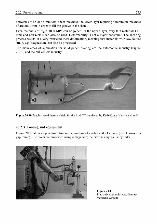
20.2 Punch riveting 255
between s = 1.5 and 5 mm total sheet thickness, the lower layer requiring a minimum thickness of around 1 mm in order to fill the groove in the shank. Even materials of Rm > 1000 MPa can be joined. In the upper layer, very thin materials (< 1 mm) and non-metals can also be used. Deformability is not a major constraint. The shearing process results in a very restricted local deformation, meaning that materials with low failure strain, e.g. Magnesium, can also be processed. The main areas of application for solid punch riveting are the automobile industry (Figure 20.10) and the rail vehicle industry.
Figure 20.10 Punch-riveted thermal shield for the Audi TT (produced by Kerb-Konus-Vertriebs-GmbH)
20.2.3 Tooling and equipment Figure 20.11 shows a punch-riveting unit consisting of a robot and a C-frame (also known as a gap frame). The rivets are processed using a magazine; the drive is a hydraulic cylinder.
Figure 20.11 Punch-riveting unit (Kerb-Konus-Vertriebs-GmbH)
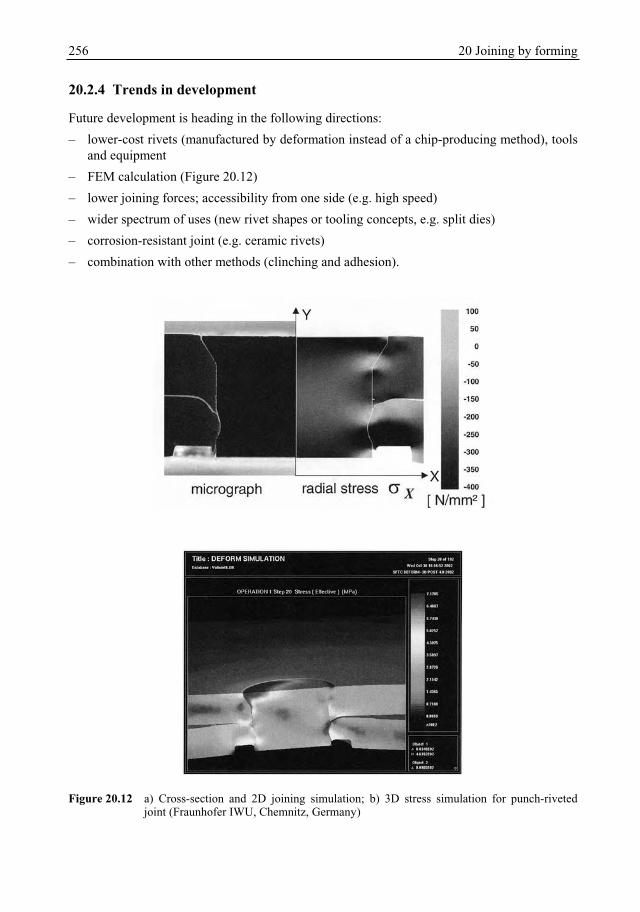
256 20 Joining by forming
20.2.4 Trends in development
Future development is heading in the following directions: – lower-cost rivets (manufactured by deformation instead of a chip-producing method), tools
and equipment – FEM calculation (Figure 20.12) – lower joining forces; accessibility from one side (e.g. high speed) – wider spectrum of uses (new rivet shapes or tooling concepts, e.g. split dies) – corrosion-resistant joint (e.g. ceramic rivets) – combination with other methods (clinching and adhesion).
Figure 20.12 a) Cross-section and 2D joining simulation; b) 3D stress simulation for punch-riveted joint (Fraunhofer IWU, Chemnitz, Germany)
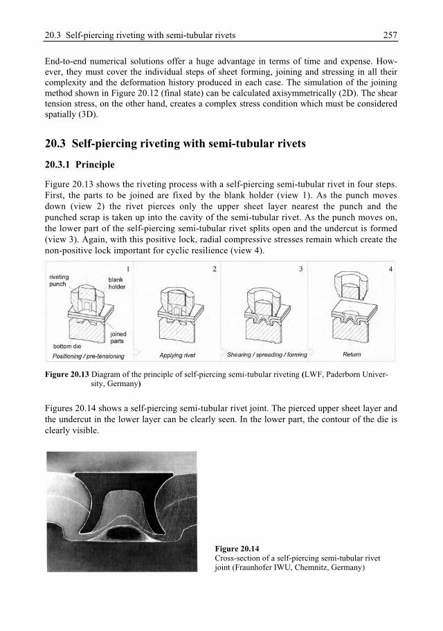
20.3 Self-piercing riveting with semi-tubular rivets 257
End-to-end numerical solutions offer a huge advantage in terms of time and expense. How-ever, they must cover the individual steps of sheet forming, joining and stressing in all their complexity and the deformation history produced in each case. The simulation of the joining method shown in Figure 20.12 (final state) can be calculated axisymmetrically (2D). The shear tension stress, on the other hand, creates a complex stress condition which must be considered spatially (3D).
20.3 Self-piercing riveting with semi-tubular rivets
20.3.1 Principle
Figure 20.13 shows the riveting process with a self-piercing semi-tubular rivet in four steps. First, the parts to be joined are fixed by the blank holder (view 1). As the punch moves down (view 2) the rivet pierces only the upper sheet layer nearest the punch and the punched scrap is taken up into the cavity of the semi-tubular rivet. As the punch moves on, the lower part of the self-piercing semi-tubular rivet splits open and the undercut is formed (view 3). Again, with this positive lock, radial compressive stresses remain which create the non-positive lock important for cyclic resilience (view 4).
Figure 20.13 Diagram of the principle of self-piercing semi-tubular riveting (LWF, Paderborn Univer-sity, Germany)
Figures 20.14 shows a self-piercing semi-tubular rivet joint. The pierced upper sheet layer and the undercut in the lower layer can be clearly seen. In the lower part, the contour of the die is clearly visible.
Figure 20.14 Cross-section of a self-piercing semi-tubular rivet joint (Fraunhofer IWU, Chemnitz, Germany)
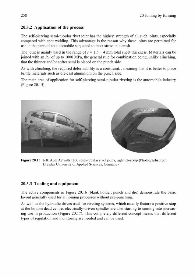
258 20 Joining by forming
20.3.2 Application of the process
The self-piercing semi-tubular rivet joint has the highest strength of all such joints, especially compared with spot welding. This advantage is the reason why these joints are permitted for use in the parts of an automobile subjected to most stress in a crash. The joint is mainly used in the range of s = 1.5 4 mm total sheet thickness. Materials can be joined with an Rm of up to 1000 MPa, the general rule for combination being, unlike clinching, that the thinner and/or softer semi is placed on the punch side. As with clinching, the required deformability is a constraint. , meaning that it is better to place brittle materials such as die-cast aluminium on the punch side. The main area of application for self-piercing semi-tubular riveting is the automobile industry (Figure 20.15).
Figure 20.15 left: Audi A2 with 1800 semi-tubular rivet joints, right: close-up (Photographs from Dresden University of Applied Sciences, Germany)
20.3.3 Tooling and equipment
The active components in Figure 20.16 (blank holder, punch and die) demonstrate the basic layout generally used for all joining processes without pre-punching. As well as the hydraulic drives used for riveting systems, which usually feature a positive stop at the bottom dead centre, electrically-driven spindles are also starting to coming into increas-ing use in production (Figure 20.17). This completely different concept means that different types of regulation and monitoring are needed and can be used.
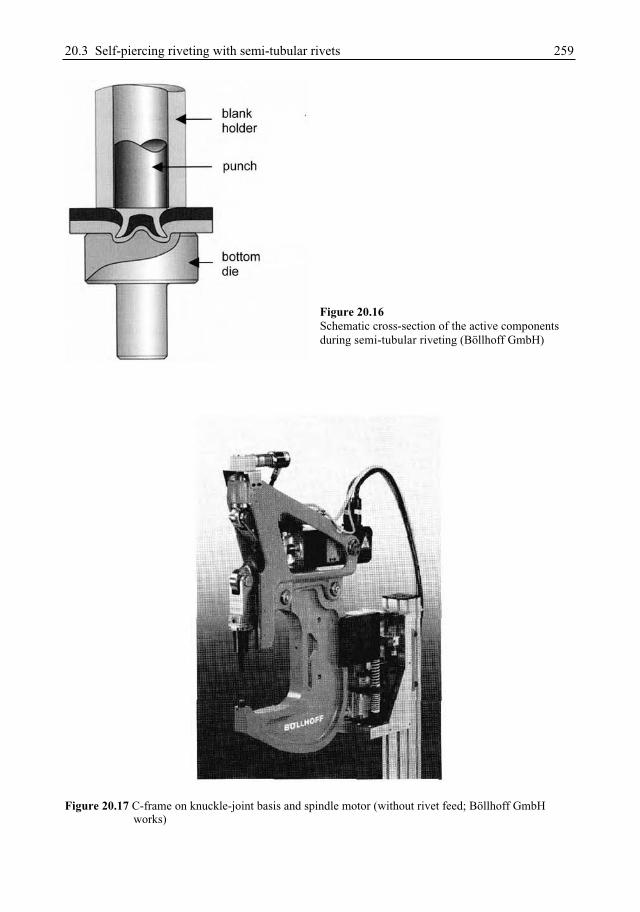
20.3 Self-piercing riveting with semi-tubular rivets 259
Figure 20.16 Schematic cross-section of the active components during semi-tubular riveting (Böllhoff GmbH)
Figure 20.17 C-frame on knuckle-joint basis and spindle motor (without rivet feed; Böllhoff GmbH works)
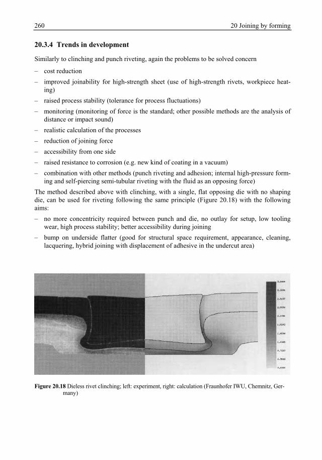
260 20 Joining by forming
20.3.4 Trends in development
Similarly to clinching and punch riveting, again the problems to be solved concern
– cost reduction – improved joinability for high-strength sheet (use of high-strength rivets, workpiece heat-
ing) – raised process stability (tolerance for process fluctuations) – monitoring (monitoring of force is the standard; other possible methods are the analysis of
distance or impact sound) – realistic calculation of the processes – reduction of joining force – accessibility from one side – raised resistance to corrosion (e.g. new kind of coating in a vacuum) – combination with other methods (punch riveting and adhesion; internal high-pressure form-
ing and self-piercing semi-tubular riveting with the fluid as an opposing force) The method described above with clinching, with a single, flat opposing die with no shaping die, can be used for riveting following the same principle (Figure 20.18) with the following aims: – no more concentricity required between punch and die, no outlay for setup, low tooling
wear, high process stability; better accessibility during joining – bump on underside flatter (good for structural space requirement, appearance, cleaning,
lacquering, hybrid joining with displacement of adhesive in the undercut area)
Figure 20.18 Dieless rivet clinching; left: experiment, right: calculation (Fraunhofer IWU, Chemnitz, Ger-many)

Part II: Presses
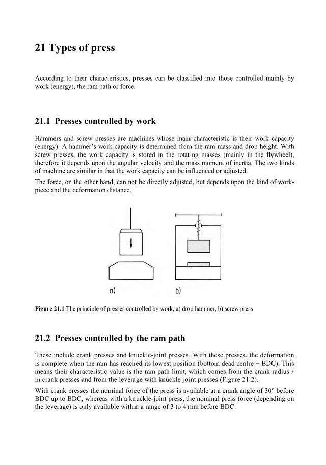
21 Types of press
According to their characteristics, presses can be classified into those controlled mainly by work (energy), the ram path or force.
21.1 Presses controlled by work
Hammers and screw presses are machines whose main characteristic is their work capacity (energy). A hammer’s work capacity is determined from the ram mass and drop height. With screw presses, the work capacity is stored in the rotating masses (mainly in the flywheel), therefore it depends upon the angular velocity and the mass moment of inertia. The two kinds of machine are similar in that the work capacity can be influenced or adjusted. The force, on the other hand, can not be directly adjusted, but depends upon the kind of work-piece and the deformation distance.
Figure 21.1 The principle of presses controlled by work, a) drop hammer, b) screw press
21.2 Presses controlled by the ram path
These include crank presses and knuckle-joint presses. With these presses, the deformation is complete when the ram has reached its lowest position (bottom dead centre BDC). This means their characteristic value is the ram path limit, which comes from the crank radius rin crank presses and from the leverage with knuckle-joint presses (Figure 21.2). With crank presses the nominal force of the press is available at a crank angle of 30° before BDC up to BDC, whereas with a knuckle-joint press, the nominal press force (depending on the leverage) is only available within a range of 3 to 4 mm before BDC.
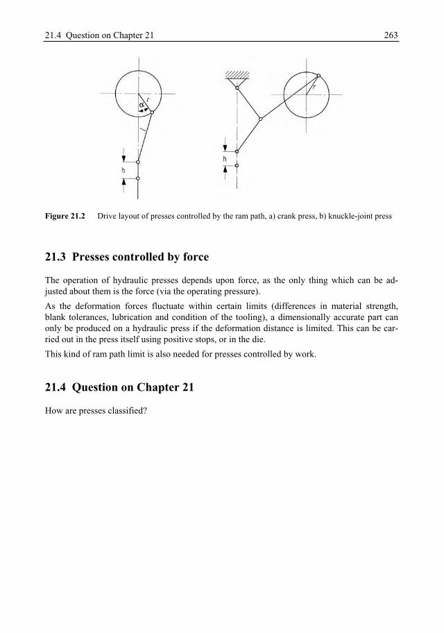
21.4 Question on Chapter 21 263
Figure 21.2 Drive layout of presses controlled by the ram path, a) crank press, b) knuckle-joint press
21.3 Presses controlled by force
The operation of hydraulic presses depends upon force, as the only thing which can be ad-justed about them is the force (via the operating pressure). As the deformation forces fluctuate within certain limits (differences in material strength, blank tolerances, lubrication and condition of the tooling), a dimensionally accurate part can only be produced on a hydraulic press if the deformation distance is limited. This can be car-ried out in the press itself using positive stops, or in the die. This kind of ram path limit is also needed for presses controlled by work.
21.4 Question on Chapter 21
How are presses classified?

22 Hammers
22.1 Columns and frames Figure 22.1 shows the most important types of hammer column.
Figure 22.1 Hammer frame designs. I) Single-column frame, 1 anvil, 2 column, 3 ram guide, 4 ram, 5 air cylinder; II) structural designs of two-column frames, a) anvil 1, side column 2 and head 3, separate, b) side columns and head in one piece, c) anvil, side columns and head in one piece
22.2 Types of hammer
Hammers are classified according to the drive design into: drop hammers double-acting hammers counterblow hammers. With drop hammers, the ram drops freely. The impact energy comes from the mass of the ram and the drop height. Belts, chains or with hydraulic drives the piston rod are used to lift the ram. At present, hydraulic lifting devices are mainly used for reasons of cost-efficiency.
W = m · g · HWith double-acting hammers a pressure medium (air or compressed oil) is used as well as the drop energy to further accelerate the ram. This means that higher ram impact velocities can be achieved, thus raising the impact energy.
W = 22m

Tab
le 2
2.1
Type
s of h
amm
er
Ham
mer
s with
anv
il bl
ock
Ham
mer
s with
out a
nvil
bloc
k D
rop
ham
mer
s C
ount
erbl
ow h
amm
ers
Cou
plin
g w
ith
belt
with
cha
in
with
hyd
raul
ics
with
ban
ds
with
hyd
raul
ics
Elem
ents
and
par
amet
ers
Dou
ble-
actin
g ha
m-
mer
s
Lifti
ng m
echa
nism
B
elt
Cha
inPi
ston
rod
Pist
on ro
d D
iffer
entia
l pis
ton
Pres
sure
mec
hani
sm
––
–Pi
ston
Pist
on
Ener
gy fo
r wor
king
mo-
vem
ent
Free
fall
Air
Com
pres
sed
oil
Air
Com
pres
sed
oil
Com
pres
sed
oil
Max
. dro
p he
ight
in m
2
1.3
1.3
1.3
––
Ram
acc
eler
atio
n a
(m/s
) a
ga
ga
gIm
pact
vel
ocity
A
(m/s
)ap
prox
. 5
66
– 8
8 –
14
Wor
k ca
paci
ty W
=m
· 2 /
2m
· g
· hm
· g
· H+
P · 1
0–1 ·
A · H
12
2(
)2
mm
Max
. wor
k ca
paci
ty W
(kN
m
)80
100
160
200
1000
1000
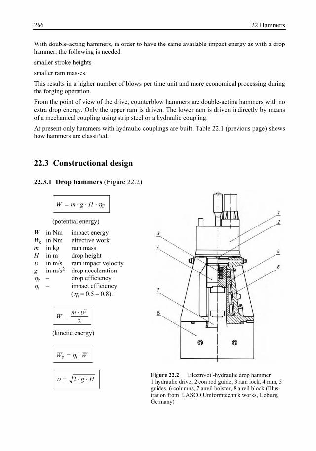
266 22 Hammers
With double-acting hammers, in order to have the same available impact energy as with a drop hammer, the following is needed: smaller stroke heights smaller ram masses. This results in a higher number of blows per time unit and more economical processing during the forging operation. From the point of view of the drive, counterblow hammers are double-acting hammers with no extra drop energy. Only the upper ram is driven. The lower ram is driven indirectly by means of a mechanical coupling using strip steel or a hydraulic coupling. At present only hammers with hydraulic couplings are built. Table 22.1 (previous page) shows how hammers are classified.
22.3 Constructional design
22.3.1 Drop hammers (Figure 22.2)
FW m g H
(potential energy)
W in Nm impact energy We in Nm effective work m in kg ram mass H in m drop height
in m/s ram impact velocity g in m/s2 drop acceleration
F – drop efficiency i – impact efficiency
( i = 0.5 – 0.8).
2
2mW
(kinetic energy)
e iW W
2 g H Figure 22.2 Electro/oil-hydraulic drop hammer 1 hydraulic drive, 2 con rod guide, 3 ram lock, 4 ram, 5 guides, 6 columns, 7 anvil bolster, 8 anvil block (Illus-tration from LASCO Umformtechnik works, Coburg, Germany)

22.3 Constructional design 267
The hydraulic drop hammer shown in Figure 22.2 has a three-part frame. The materials used are:
a) Anvil and side columns: grey cast iron with added steel. This special cast iron is a better damper and has a more ho-
mogeneous structure than cast steel. b) Ram: high-alloy, hardened and tempered cast electric steel or
quenched and tempered steel. c) Guides: hardened, ground steel prism guides.
For hammers with an anvil block, the impact effect depends upon the ratio of
impact energymass of the anvil
.
Modern hammers have values of Q = 1.0 – 1.2.
a
(Nm)m (kg)WQ
The impact efficiency of a hammer is determined by this value. In the past, the following ratio was used to measure the impact effect:
anvil mass (kg) 10 20toram mass (kg) 1 1
However, as the anvil mass remains relatively small with small ram masses, this mass ratio can not be used to measure the impact effect.
22.3.2 Double-acting hammers With double-acting hammers the work capacity of the falling ram is raised further by a propel-lant (air or compressed oil).
W = m · g · H + p · 10–1 · A · H
1( 10 )W H m g p A
W in Nm impact energy m in kg ram mass g in m/s2 drop acceleration H in mm drop height p in bar operating pressure A in cm2 piston area 10–1 conversion from bar to N/cm2
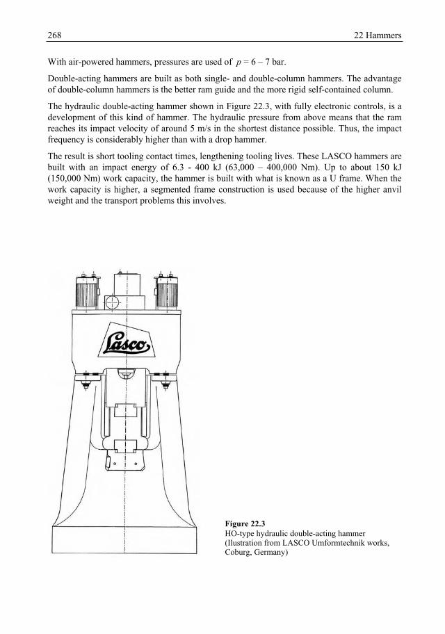
268 22 Hammers
With air-powered hammers, pressures are used of p = 6 – 7 bar.
Double-acting hammers are built as both single- and double-column hammers. The advantage of double-column hammers is the better ram guide and the more rigid self-contained column.
The hydraulic double-acting hammer shown in Figure 22.3, with fully electronic controls, is a development of this kind of hammer. The hydraulic pressure from above means that the ram reaches its impact velocity of around 5 m/s in the shortest distance possible. Thus, the impact frequency is considerably higher than with a drop hammer.
The result is short tooling contact times, lengthening tooling lives. These LASCO hammers are built with an impact energy of 6.3 - 400 kJ (63,000 – 400,000 Nm). Up to about 150 kJ (150,000 Nm) work capacity, the hammer is built with what is known as a U frame. When the work capacity is higher, a segmented frame construction is used because of the higher anvil weight and the transport problems this involves.
Figure 22.3 HO-type hydraulic double-acting hammer (Ilustration from LASCO Umformtechnik works, Coburg, Germany)
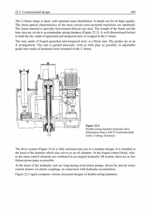
22.3 Constructional design 269
The U-frame shape is ideal, with optimum mass distribution. It stands out for its high rigidity. The stress-optical characteristics of the most crucial cross-sectional transitions are optimised. The frame material is specially heat-treated alloyed cast steel. The weight of the frame and the base area are set up to accommodate spring dampers (Figure 22.3). A well-dimensioned bolster to hold the die, made of quenched and tempered steel, is wedged in the U frame. The ram, made of forged quenched and tempered steel, is a block ram. The guides are in an X arrangement. The ram is guided precisely, with as little play as possible, in adjustable guide bars made of hardened steel mounted in the U frame.
Figure 22.4 Double-acting hammer hydraulic drive (Illustration from LASCO Umformtechnik works, Coburg, Germany)
The drive system (Figure 22.4) is fully enclosed and cast in a modular design. It is installed in the head of the hammer which also serves as an oil chamber. In the forged control block, whe-re the main control elements are combined in an integral hydraulic lift system, there are as few failure-prone pipes as possible. At the heart of the hydraulic unit are long-lasting axial piston pumps, driven by special rotary current motors via elastic couplings, in connection with hydraulic accumulators. Figure 22.5 again compares various structural designs of double-acting hammers.
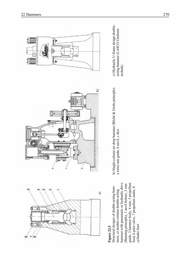
22 Hammers 270
Figu
re 2
2.5
Stru
ctur
al d
esig
ns o
f dou
ble-
actin
g ha
m-
mer
s, a)
dou
ble-
colu
mn
doub
le-a
ctin
g ha
mm
er w
ith p
neum
atic
or h
ydra
ulic
driv
e (B
anni
ng p
rinci
ple)
, 1 a
nvil
bols
ter,
2 ra
m
guid
e, 3
ham
mer
bod
y, 4
ram
, 5 p
rope
llant
fe
ed, 6
pilo
t val
ve, 7
pro
pella
nt o
utle
t, 8
cylin
der l
iner
b) S
ingl
e-co
lum
n ai
r dro
p ha
mm
er (B
êché
& G
rohs
prin
cipl
e).
a ex
tra ra
m g
uide
, b a
nvil,
c d
ies
c) H
ydra
ulic
U-f
ram
e de
sign
dou
ble-
actin
g ha
mm
er (L
ASC
O U
mfo
rm-
tech
nik)
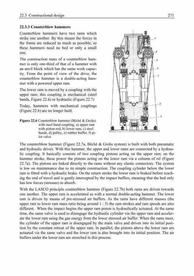
22.3 Constructional design 271
22.3.3 Counterblow hammersCounterblow hammers have two rams which strike one another. By this means the forces in the frame are reduced as much as possible, so these hammers need no bed or only a small one.The construction mass of a counterblow ham-mer is only one-third of that of a hammer with an anvil block which has the same work capac-ity. From the point of view of the drive, the counterblow hammer is a double-acting ham-mer with a powered upper ram. The lower ram is moved by a coupling with the upper ram; this coupling is mechanical (steel bands, Figure 22.6) or hydraulic (Figure 22.7) Today, hammers with mechanical couplings (Figure 22.6) are no longer built.
Figure 22.6 Counterblow hammer (Bêché & Grohs) with steel band coupling, a) upper ram with piston rod, b) lower ram, c) steel bands, d) pulley, e) rubber buffer, f) pi-lot valve
The counterblow hammer (Figure 22.7a, Bêché & Grohs system) is built with both pneumatic and hydraulic drives. With this hammer, the upper and lower rams are connected by a hydrau-lic coupling. It basically consists of two coupling pistons acting on the upper ram; on the hammer stroke, these power the pistons acting on the lower ram via a column of oil (Figure 22.7a). The pistons are linked directly to the rams without any elastic connectors. The system is low on maintenance due to its simple construction. The coupling cylinder below the lower ram is fitted with a hydraulic brake. On the return stroke the lower ram is braked before reach-ing the end of travel and is gently intercepted by the impact buffers, meaning that the bed only has low forces (stresses) to absorb.With the LASCO principle counterblow hammer (Figure 22.7b) both rams are driven towards one another. The upper ram is accelerated as with a normal double-acting hammer. The lower ram is driven by means of pre-stressed air buffers. As the rams have different masses (the upper ram to lower ram mass ratio being around 1 : 5) the ram strokes and ram speeds are also different. When the impact begins the upper ram piston is hydraulically actuated. At the same time, the same valve is used to disengage the hydraulic cylinder via the upper ram and acceler-ate the lower ram using the gas energy from the lower stressed air buffer. When the rams meet, the cylinder of the upper ram is disengaged by the main valve and driven into its initial posi-tion by the constant retreat of the upper ram. In parallel, the pistons above the lower ram are actuated via the same valve and the lower ram is also brought into its initial position. The air buffers under the lower ram are stretched in this process.
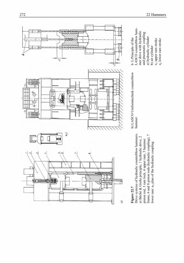
272 22 Hammers
b 1)
Prin
cipl
e of
the
LASC
O c
ount
erbl
ow h
am-
mer
driv
e w
ith h
ydra
ulic
an
d pn
eum
atic
cou
plin
g a)
hyd
raul
ic c
ylin
der
b) a
ir cy
linde
r s 1
upp
er ra
m st
roke
s 2
low
er ra
m st
roke
b) L
ASC
O U
mfo
rmte
chni
k co
unte
rblo
w
ham
mer
Figu
re 2
2.7
Driv
e sy
stem
s of h
ydra
ulic
cou
nter
blow
ham
mer
s. a)
Bêc
hé &
Gro
hs p
rinci
ple,
1 h
ydra
ulic
driv
e, 2
pi
ston
rod,
3 ra
m lo
ck, 4
upp
er ra
m, 5
ham
mer
fr
ame,
6 a
nd 8
pis
ton
rods
(hyd
raul
ic c
oupl
ing)
, 7
low
er ra
m: a
1 pla
n of
the
hydr
aulic
cou
plin
g.

273
As the ram drive is controlled by a single valve, the impact plane (forging plane) is precisely fixed. The lower ram stroke is about 120 150 mm. Its low impact velocity of around 1.2 m/s means that both flat and complicated forgings lie steady in the die on impact. The resultant impact velocity is around 6 8 m/s. With these hammers the maximum ram impact velocity is around 8 to 14 m/s. The impact energy can be determined from the resultant impact velocity of the rams and the ram masses.
Impact energy:
2 21 2( )2 2
m m mW
W in Nm impact energy m1 in kg mass of the upper ram m2 in kg mass of the lower ram
in m/s final velocity before impact.
In order for the counterblow hammer to open automatically when the machine stops, the lower ram mass is set about 5 % higher than that of the upper ram. Thus, for hammers with band couplings
1 22.052
mW
22.4 Fields of application for hammers Table 22.2 shows which kinds of hammers are used with different types of impression-die forging.
Table 22.2 Uses for hammer types
Hammer type Application
Drop hammers small to medium-sized impression-die forgings, e.g. wrenches, levers, coupling components
Double-acting hammers medium to large-sized impression-die forgings,
(double-column) e.g. camshafts, flanges
Counterblow hammers difficult and extremely difficult impression-die forgings, e.g. large crankshafts, levers which are hard to form, large coupling components

274 22 Hammers
22.5 Example Where: Drop height H = 1.6 m Ram mass m = 500 kg Drop efficiency F = 0.7 Impact efficiency i = 0.8.
Find: theoretical ram impact velocity , effective work.
Solution:Ram impact velocity:
22 2 9.81 m/s 1.6 m 5.6 m/sg H
The actual impact velocity is lower due to friction losses in the guides.
actual = fr · fr = 0.8 – 0.9 Impact energy:
W = m · q · H · F = 500 kg · 9.81 m/s2 · 1.6 m · 0.7 W = 5493.6 N m 5.5 kN m
Effective work: We = i · W = 0.8 · 5.5 kN m = 4.4 kN m
If the actual impact velocity is known then the impact energy can also be determined thus:
actual = fr · = 0.84 · 5.6 m/s = 4.7 m/s
fr = 0.84 selected.
W =2 2 2
3500 kg 4.7 m / s 5.5 kN m
2 2 10m
22.6 Exercise on Chapter 22
1. What kinds of hammer frame construction are there? 2. How are hammers classified? 3. What advantages do double-acting hammers have over drop hammers? 4. When are counterblow hammers used?
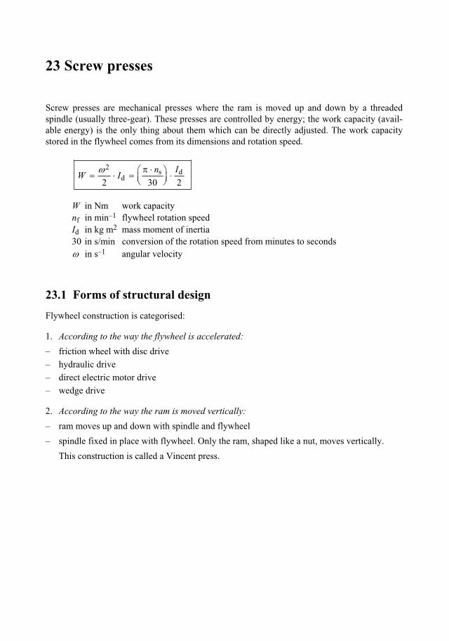
23 Screw presses
Screw presses are mechanical presses where the ram is moved up and down by a threaded spindle (usually three-gear). These presses are controlled by energy; the work capacity (avail-able energy) is the only thing about them which can be directly adjusted. The work capacity stored in the flywheel comes from its dimensions and rotation speed.
2 s dd2 30 2
n IW I
W in Nm work capacity nf in min–1 flywheel rotation speed Id in kg m2 mass moment of inertia 30 in s/min conversion of the rotation speed from minutes to seconds
in s–1 angular velocity
23.1 Forms of structural design Flywheel construction is categorised:
1. According to the way the flywheel is accelerated:– friction wheel with disc drive – hydraulic drive – direct electric motor drive – wedge drive
2. According to the way the ram is moved vertically:– ram moves up and down with spindle and flywheel – spindle fixed in place with flywheel. Only the ram, shaped like a nut, moves vertically.
This construction is called a Vincent press.
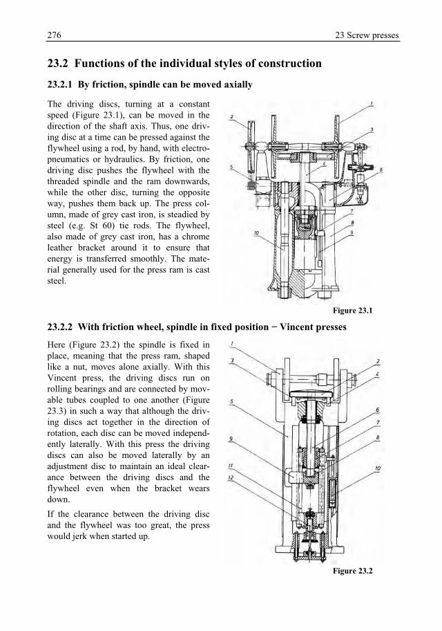
276 23 Screw presses
23.2 Functions of the individual styles of construction
23.2.1 By friction, spindle can be moved axially
The driving discs, turning at a constant speed (Figure 23.1), can be moved in the direction of the shaft axis. Thus, one driv-ing disc at a time can be pressed against the flywheel using a rod, by hand, with electro-pneumatics or hydraulics. By friction, one driving disc pushes the flywheel with the threaded spindle and the ram downwards, while the other disc, turning the opposite way, pushes them back up. The press col-umn, made of grey cast iron, is steadied by steel (e.g. St 60) tie rods. The flywheel, also made of grey cast iron, has a chrome leather bracket around it to ensure that energy is transferred smoothly. The mate-rial generally used for the press ram is cast steel.
Figure 23.1
23.2.2 With friction wheel, spindle in fixed position Vincent presses
Here (Figure 23.2) the spindle is fixed in place, meaning that the press ram, shaped like a nut, moves alone axially. With this Vincent press, the driving discs run on rolling bearings and are connected by mov-able tubes coupled to one another (Figure 23.3) in such a way that although the driv-ing discs act together in the direction ofrotation, each disc can be moved independ-ently laterally. With this press the driving discs can also be moved laterally by an adjustment disc to maintain an ideal clear-ance between the driving discs and the flywheel even when the bracket wears down.If the clearance between the driving disc and the flywheel was too great, the press would jerk when started up.
Figure 23.2
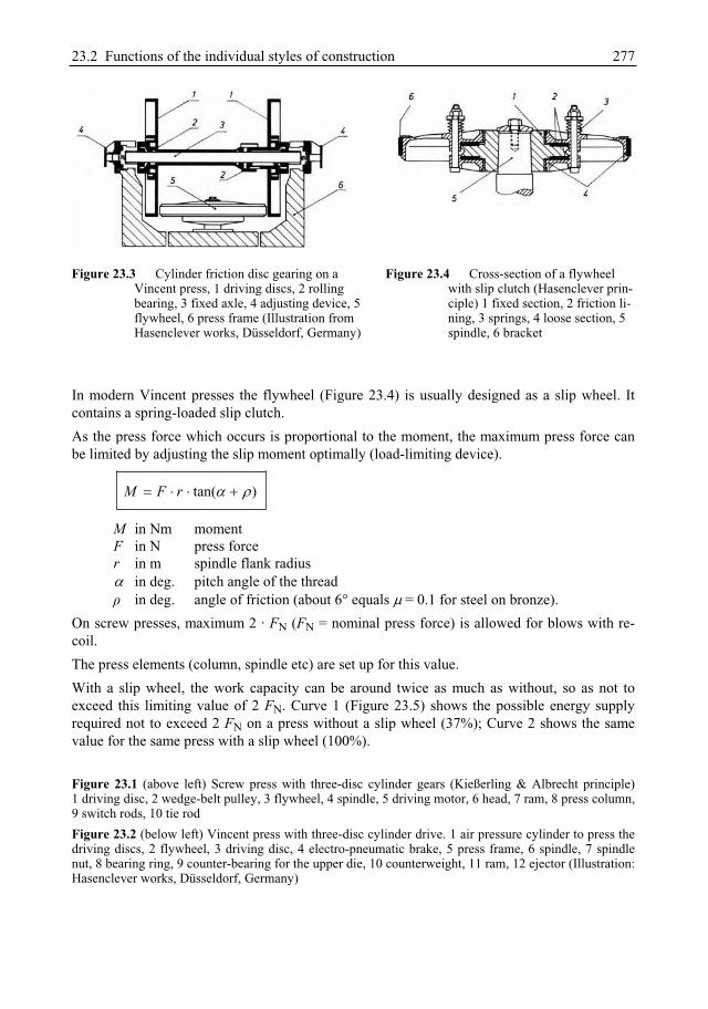
23.2 Functions of the individual styles of construction 277
Figure 23.3 Cylinder friction disc gearing on a Vincent press, 1 driving discs, 2 rolling bearing, 3 fixed axle, 4 adjusting device, 5 flywheel, 6 press frame (Illustration from Hasenclever works, Düsseldorf, Germany)
Figure 23.4 Cross-section of a flywheel with slip clutch (Hasenclever prin-ciple) 1 fixed section, 2 friction li-ning, 3 springs, 4 loose section, 5 spindle, 6 bracket
In modern Vincent presses the flywheel (Figure 23.4) is usually designed as a slip wheel. It contains a spring-loaded slip clutch. As the press force which occurs is proportional to the moment, the maximum press force can be limited by adjusting the slip moment optimally (load-limiting device).
tan( )M F r
M in Nm moment F in N press force r in m spindle flank radius
in deg. pitch angle of the thread in deg. angle of friction (about 6° equals = 0.1 for steel on bronze).
On screw presses, maximum 2 · FN (FN = nominal press force) is allowed for blows with re-coil. The press elements (column, spindle etc) are set up for this value. With a slip wheel, the work capacity can be around twice as much as without, so as not to exceed this limiting value of 2 FN. Curve 1 (Figure 23.5) shows the possible energy supply required not to exceed 2 FN on a press without a slip wheel (37%); Curve 2 shows the same value for the same press with a slip wheel (100%).
Figure 23.1 (above left) Screw press with three-disc cylinder gears (Kießerling & Albrecht principle) 1 driving disc, 2 wedge-belt pulley, 3 flywheel, 4 spindle, 5 driving motor, 6 head, 7 ram, 8 press column, 9 switch rods, 10 tie rod Figure 23.2 (below left) Vincent press with three-disc cylinder drive. 1 air pressure cylinder to press the driving discs, 2 flywheel, 3 driving disc, 4 electro-pneumatic brake, 5 press frame, 6 spindle, 7 spindle nut, 8 bearing ring, 9 counter-bearing for the upper die, 10 counterweight, 11 ram, 12 ejector (Illustration: Hasenclever works, Düsseldorf, Germany)
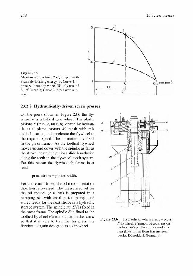
278 23 Screw presses
Figure 23.5 Maximum press force 2 FN subject to the available forming energy W. Curve 1: press without slip wheel (W only around 1/3 of Curve 2) Curve 2: press with slip wheel
23.2.3 Hydraulically-driven screw presses
On the press shown in Figure 23.6 the fly-wheel F is a helical gear wheel. The plastic pinions P (min. 2, max. 8), driven by hydrau-lic axial piston motors M, mesh with this helical gearing and accelerate the flywheel to the required speed. The oil motors are fixed in the press frame. As the toothed flywheel moves up and down with the spindle as far as the stroke length, the pinions slide lengthwise along the teeth in the flywheel tooth system. For this reason the flywheel thickness is at least
press stroke + pinion width.
For the return stroke, the oil motors’ rotation direction is reversed. The pressurised oil forthe oil motors (210 bar) is prepared in a pumping set with axial piston pumps and stored ready for the next stroke in a hydraulic storage system. The spindle nut SN is fixed in the press frame. The spindle S is fixed to the toothed flywheel F and mounted in the ram Rso that it is able to turn. In this press, the flywheel is again designed as a slip wheel.
Figure 23.6 Hydraulically-driven screw press. F flywheel, P pinion, M axial piston motors, SN spindle nut, S spindle, Rram (Illustration from Hasenclever works, Düsseldorf, Germany)
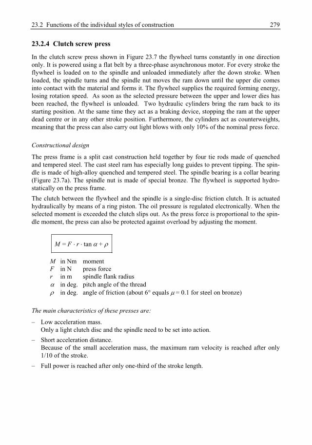
23.2 Functions of the individual styles of construction 279
23.2.4 Clutch screw press
In the clutch screw press shown in Figure 23.7 the flywheel turns constantly in one direction only. It is powered using a flat belt by a three-phase asynchronous motor. For every stroke the flywheel is loaded on to the spindle and unloaded immediately after the down stroke. When loaded, the spindle turns and the spindle nut moves the ram down until the upper die comes into contact with the material and forms it. The flywheel supplies the required forming energy, losing rotation speed. As soon as the selected pressure between the upper and lower dies has been reached, the flywheel is unloaded. Two hydraulic cylinders bring the ram back to its starting position. At the same time they act as a braking device, stopping the ram at the upper dead centre or in any other stroke position. Furthermore, the cylinders act as counterweights, meaning that the press can also carry out light blows with only 10% of the nominal press force.
Constructional design
The press frame is a split cast construction held together by four tie rods made of quenched and tempered steel. The cast steel ram has especially long guides to prevent tipping. The spin-dle is made of high-alloy quenched and tempered steel. The spindle bearing is a collar bearing (Figure 23.7a). The spindle nut is made of special bronze. The flywheel is supported hydro-statically on the press frame. The clutch between the flywheel and the spindle is a single-disc friction clutch. It is actuated hydraulically by means of a ring piston. The oil pressure is regulated electronically. When the selected moment is exceeded the clutch slips out. As the press force is proportional to the spin-dle moment, the press can also be protected against overload by adjusting the moment.
tanM = F r +
M in Nm moment F in N press force r in m spindle flank radius
in deg. pitch angle of the thread in deg. angle of friction (about 6° equals = 0.1 for steel on bronze)
The main characteristics of these presses are:
– Low acceleration mass. Only a light clutch disc and the spindle need to be set into action.
– Short acceleration distance. Because of the small acceleration mass, the maximum ram velocity is reached after only 1/10 of the stroke.
– Full power is reached after only one-third of the stroke length.
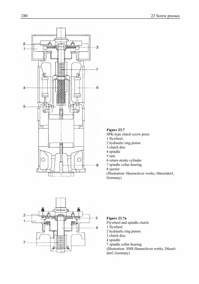
280 23 Screw presses
Figure 23.7 SPK-type clutch screw press 1 flywheel, 2 hydraulic ring piston 3 clutch disc 4 spindle 5 ram 6 return stroke cylinder 7 spindle collar bearing 8 ejector (Illustration: Hasenclever works, Düsseldorf, Germany)
Figure 23.7a Flywheel and spindle clutch 1 flywheel 2 hydraulic ring piston 3 clutch disc 4 spindle 7 spindle collar bearing(Illustration: SMS Hasenclever works, Düssel-dorf, Germany)
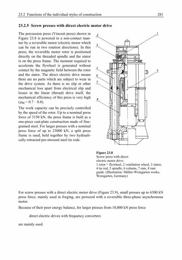
23.2 Functions of the individual styles of construction 281
23.2.5 Screw presses with direct electric motor drive
The percussion press (Vincent press) shown in Figure 23.8 is powered in a non-contact man-ner by a reversible motor (electric motor which can be run in two rotation directions). In this press, the reversible motor rotor is positioned directly on the threaded spindle and the stator is on the press frame. The moment required to accelerate the flywheel is generated without contact by the magnetic field between the rotor and the stator. The direct electric drive means there are no parts which are subject to wear in the drive system. As there is no slip or other mechanical loss apart from electrical slip and losses in the linear (thread) drive itself, the mechanical efficiency of this press is very high ( M = 0.7 – 0.8). The work capacity can be precisely controlled by the speed of the rotor. Up to a nominal press force of 3150 kN, the press frame is built as a one-piece cast-plate construction made of fine-grained steel. For larger presses with a nominal press force of up to 23000 kN, a split press frame is used, held together by two hydrauli-cally-retracted pre-stressed steel tie rods.
Figure 23.8Screw press with directelectric motor drive. 1 rotor = flywheel, 2 ventilation wheel, 3 stator, 4 tie rod, 5 spindle, 6 column, 7 ram, 8 ram guide. (Illustration: Müller-Weingarten works, Weingarten, Germany)
For screw presses with a direct electric motor drive (Figure 23.9), small presses up to 6300 kN press force, mainly used in forging, are powered with a reversible three-phase asynchronous motor. Because of their poor energy balance, for larger presses from 10,000 kN press force
direct electric drives with frequency converters
are mainly used.
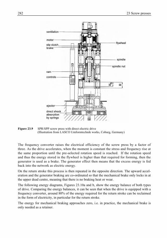
282 23 Screw presses
Figure 23.9 SPR/SPP screw press with direct electric drive (Illustration from LASCO Umformtechnik works, Coburg, Germany)
The frequency converter raises the electrical efficiency of the screw press by a factor of three. As the drive accelerates, when the moment is constant the stress and frequency rise at the same proportion until the pre-selected rotation speed is reached. If the rotation speed and thus the energy stored in the flywheel is higher than that required for forming, then the generator is used as a brake. The generator effect then means that the excess energy is fed back into the network as electric energy. On the return stroke this process is then repeated in the opposite direction. The upward accel-eration and the generator braking are co-ordinated so that the mechanical brake only locks in at the upper dead centre, meaning that there is no braking heat or wear. The following energy diagrams, Figures 23.10a and b, show the energy balance of both types of drive. Comparing the energy balances, it can be seen that when the drive is equipped with a frequency converter, around 80% of the energy required for the return stroke can be reclaimed in the form of electricity, in particular for the return stroke. The energy for mechanical braking approaches zero, i.e. in practice, the mechanical brake is only needed as a retainer.
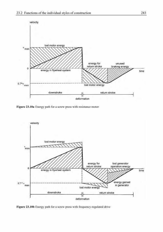
23.2 Functions of the individual styles of construction 283
Figure 23.10a Energy path for a screw press with resistance motor
Figure 23.10b Energy path for a screw press with frequency-regulated drive

284 23 Screw presses
The energy from the electricity network (useful energy) is equal to the gross energy of the press plus electric and mechanical losses. With a frequency-regulated drive the total energy is reduced by the amount of energy which flows back into the network due to the generator effect during braking. With the resistance rotor this energy is lost as heat. The advantages of the frequency-regulated drive with reactive current compensation are: – lower load on electricity network – lower energy costs – low wear in clutch and brake – lower maintenance costs – shorter cycle times with reduced impact energy – higher efficiency.
Table 23.1 below shows the energy balance in figures, taking as an example a screw press with 10,000 kN nominal press force and 130 kWs gross energy.
Table 23.1 Energy balance
Resistance rotor [kWs] Frequency-regulated drive [kWs]
Total energy loss 480.0 161.0
Mechanical work 130.0 130.0
Energy from the network 610.0 291.0
Generator gain 0.0 49.1
Energy from the network, taking into ac-count the generator gain 610.0 241.9
Constructional design
The press frame is a multi-part cast construction whose elements (table, side columns and head) are joined to the press frame by four pre-stressed tie rods. The bronze spindle nut is held in a steel casing, thus lengthening the guide. The threaded spin-dle is forged and made of high-alloy CrNiMo steel. The shape of the thread is optimised to have an extremely high fatigue strength. The cast steel flywheel is made up of several parts with an independent load-limiting device. The ram is also made of cast steel. The extremely long, heat-neutral guide system, mounted below 45 , has nitrated guide bars. Plastic-coated support blocks, which can be adjusted from any direction, allow a very small guide clearance. By mounting the press on spring dampers to insulate it against vibration and structure-borne sound, press-induced vibrations can be almost completely avoided.
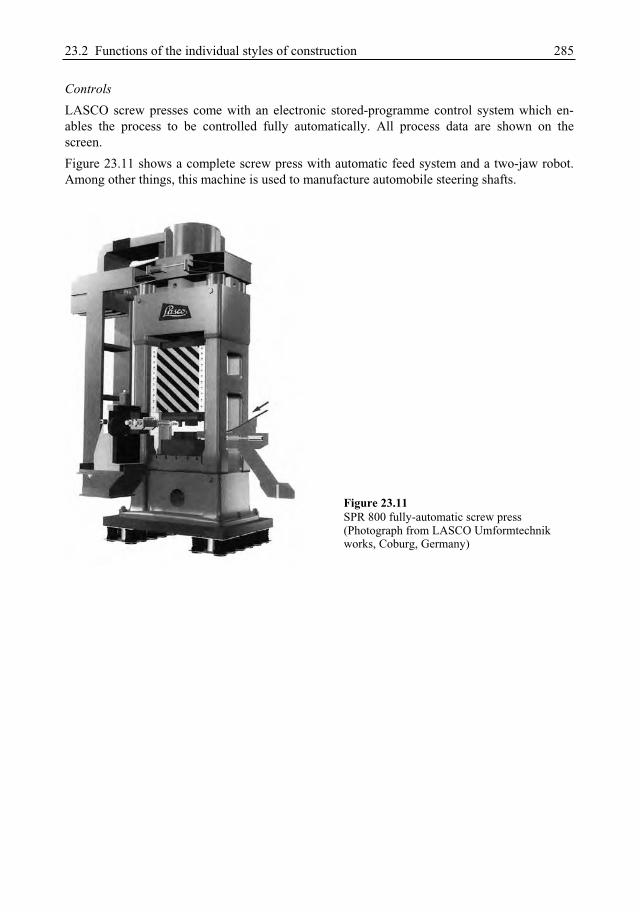
23.2 Functions of the individual styles of construction 285
ControlsLASCO screw presses come with an electronic stored-programme control system which en-ables the process to be controlled fully automatically. All process data are shown on the screen.Figure 23.11 shows a complete screw press with automatic feed system and a two-jaw robot. Among other things, this machine is used to manufacture automobile steering shafts.
Figure 23.11 SPR 800 fully-automatic screw press (Photograph from LASCO Umformtechnik works, Coburg, Germany)
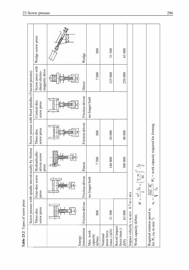
23 Screw presses 286
Tab
le 2
3.2
Type
s of s
crew
pre
ss
Scre
w p
ress
es w
ith sp
indl
e m
oved
axi
ally
by
fric
tion
Scre
w p
ress
es w
ith fi
xed
spin
dles
(Vin
cent
pre
sses
) Th
ree-
disc
sc
rew
pre
ss
Four
-dis
c sc
rew
pr
ess
Hyd
raul
ical
ly-
driv
en sc
rew
pr
ess
Thre
e-di
sc
scre
w p
ress
C
onic
al d
isc
scre
w p
ress
Sc
rew
pre
ss w
ith
dire
ct e
lect
ro-
mag
netic
driv
e
Wed
ge sc
rew
pre
ss
Ener
gy
trans
mis
sion
Fr
ictio
n-dr
iven
Fric
tion-
driv
enPi
nion
Fric
tion-
driv
enFr
ictio
n-dr
iven
Dire
ctW
edge
Max
. wor
k ca
paci
ty
(kN
m)
800
7 50
0 80
07
000
800
Nom
inal
pres
s for
ce
(max
.) (k
N)
31 5
00
140
000
20 0
00
125
000
31 5
00
Rec
oil i
mpa
ct
forc
e (m
ax.)
(kN
)63
000
no lo
nger
bui
lt
300
000
40 0
00
no lo
nger
bui
lt
250
000
63 0
00
Impa
ct v
eloc
ity v
in m
/s
0.7
to 1
m/s
W
ork
capa
city
(kN
m)
f2
2d
d2
3 02
In
IW
Req
uire
d ro
tatio
n sp
eed
n ffo
r W1 (
n f in
min
–1)
1f
d
182
Wn
IW
1 = w
ork
capa
city
requ
ired
for f
orm
ing

23.3 Calculating the parameters for screw presses 287
23.3 Calculating the parameters for screw presses
23.3.1 Work capacity
2 s dd2 2
n IW I
W in Nm work capacity (stored in the flywheel) nf in min–1 flywheel rotation speed Id in kg m2 mass moment of inertia 30 in s/min conversion figure for the rotation speed from minutes to seconds
in s–1 angular velocity.
23.3.2 Mass moment of inertia With the most common flywheel forms (Figure 23.12), the mass moment of inertia is made up of several elements.
tot webcrown hubd d d dI I I I Figure 23.12 Flywheel made up of three hollow cylinders
The mass moment of inertia for a solid cylinder can be determined as follows:
2d 2mI r
Id in kg m2 mass moment of inertia r in m radius of the solid cylinder m in kg mass of the cylinder g in kg/m3 density h in m height / length of the cylinder.
The mass m is:
2m r h
For cast iron, which is the material mainly used for flywheels, the expression · /2 can be condensed into a constant, z.
z = 37250 kg/m2 2
311382kg/mz
With this constant, z, it is easy to determine the mass moments of inertia. For the most com-mon forms, this results in:
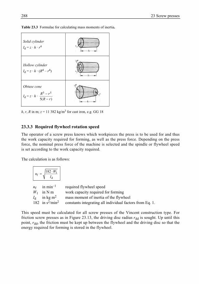
288 23 Screw presses
Table 23.3 Formulae for calculating mass moments of inertia.
Solid cylinder Id = z · h · r4
Hollow cylinder Id = z · h · (R4 – r4)
Obtuse cone
Id = z · h · 5 5
5( )R r
R r
h, r, R in m; z = 11 382 kg/m3 for cast iron, e.g. GG 18
23.3.3 Required flywheel rotation speed The operator of a screw press knows which workpieces the press is to be used for and thus the work capacity required for forming, as well as the press force. Depending on the press force, the nominal press force of the machine is selected and the spindle or flywheel speed is set according to the work capacity required.
The calculation is as follows:
1f
d
182 WnI
nf in min–1 required flywheel speed W1 in N m work capacity required for forming Id in kg m2 mass moment of inertia of the flywheel 182 in s2/min2 constants integrating all individual factors from Eq. 1.
This speed must be calculated for all screw presses of the Vincent construction type. For friction screw presses as in Figure 23.13, the driving disc radius rdd is sought. Up until this point, rdd, the friction must be kept up between the flywheel and the driving disc so that the energy required for forming is stored in the flywheel.
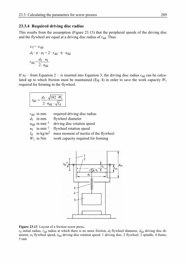
23.3 Calculating the parameters for screw presses 289
23.3.4 Required driving disc radius This results from the assumption (Figure 23.13) that the peripheral speeds of the driving disc and the flywheel are equal at a driving disc radius of rdd. Thus:
f = dd
df · · nf = 2 · rdd · · ndd
rdd = f f
dd2d n
n
If nf from Equation 2 is inserted into Equation 3, the driving disc radius rdd can be calcu-lated up to which friction must be maintained (Eq. 4) in order to save the work capacity W1required for forming in the flywheel.
f 1dd
dd d
1822
d Wr
n I
rdd in mm required driving disc radius df in mm flywheel diameter ndd in mm–1 driving disc rotation speed nf in min–1 flywheel rotation speed Id in kg/m2 mass moment of inertia of the flywheel W1 in Nm work capacity required for forming
Figure 23.13 Layout of a friction screw press.r0 initial radius, rdd radius at which there is no more friction, df flywheel diameter, ddd driving disc di-ameter, nf flywheel speed, ndd driving disc rotation speed: 1 driving disc, 2 flywheel, 3 spindle, 4 frame, 5 ram
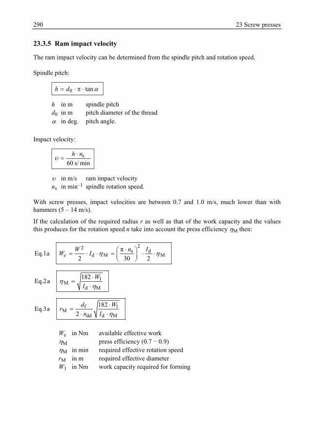
290 23 Screw presses
23.3.5 Ram impact velocity
The ram impact velocity can be determined from the spindle pitch and rotation speed.
Spindle pitch:
0 tanh d
h in m spindle pitch d0 in m pitch diameter of the thread
in deg. pitch angle.
Impact velocity:
s60 s/ min
h n
in m/s ram impact velocity ns in min–1 spindle rotation speed.
With screw presses, impact velocities are between 0.7 and 1.0 m/s, much lower than with hammers (5 – 14 m/s).
If the calculation of the required radius r as well as that of the work capacity and the values this produces for the rotation speed n take into account the press efficiency M then:
22 s dd M M
1M
d M
f 1M
dd d M
Eq.1a2 30 2
182Eq.2a
182Eq.3a2
eW n IW I
WI
d Wrn I
We in Nm available effective work M press efficiency (0.7 0.9) M in min required effective rotation speed
rM in m required effective diameter W1 in Nm work capacity required for forming
23.6 Examples 291
23.4 Advantages of screw presses (compared to hammers and crank presses)
1. Screw presses require only a small base.
2. The noise level is far lower than with hammers.
3. Screw presses are high-energy machines. For this reason, workpieces which require a lot of energy can be formed with them.
4. The dwell periods (the time during which the workpiece is being forged) are short. This means that tool life is improved.
5. The spindle thread is not self-locking. This means that a screw press can not block under stress.
6. Screw presses convert their energy abruptly, similarly to hammers. Because of the lower ram impact velocity ( = 0.7 – 1.0 m/s) the deformation resistance during hot forming is lower than with hammers ( = 5 – 14 m/s).
7. Like hammers, screw presses have no kinetically-fixed bottom dead centre. It is no lon-ger necessary to adjust the height of the tooling. Forging can also take place in a closed die, as the excess material can be balanced out in the height of the workpiece.
23.5 Typical fields of application of screw presses 1. Embossing work
Because of their hard impact, screw presses are ideal for embossing work, e.g. embossing and shaping cutlery, clutch cases made of sheet metal, etc.
2. Calibration For example, finishing gears with tolerances of around ± 0.02 mm.
3. Precision forgingForging where a hard final impression is required to ensure that the workpiece stays still and there is no spring-back. e.g. manufacturing turbine blades. These are produced to high dimensional accuracy on screw presses with no reworking apart from a polishing operation.
4. Workpieces with high energy requirementsHere, impression-die forgings are involved which require high work capacity (up to 6000 kN m) for forming.

292 23 Screw presses
23.6 Examples Example 1 In order to manufacture a workpiece, a work capacity of W1 = 8000 Nm is required. A screw press with the following specifications is available: 1. Flywheel dimensions 2. Driving disc diameter ddd = 1200 mm 3. Driving disc rotation speed ndd = 125 min–1
Figure 23.14 Flywheel
Find: Can the workpiece be manufactured on this screw press?
Solution: 1. Determining the mass moment of inertia
Id tot = Id1 + Id2 + Id3
Id1 = z · h (R4 –r4) = 11382 kg/m3 · 0.1 m (0.84 m4 – 0.74 m4) Id1 = 192.92 kg m2
Id2 = 11382 kg/m3 · 0.05 m (0.74 m4 – 0.24 m4) Id2 = 135.73 kg m2
Id3 = 11382 kg/m3 · 0.15 m (0.24 m4 – 0.044 m4) Id3 = 2.73 kg m2
Id tot = 331.38 kg m2
2. Maximum press work capacity
max
1dd dd 1ff
22 1 2f dmax
max
1200 mm 125 min 93.75 mm1600 mm
93.75 min 331.38 kg m30 2 30 2
15970 Nm
d nnd
n IW
W
As Wmax W1, the press can be used for this deformation.

23.6 Examples 293
Example 2 In a workshop there is a screw press (Figure 22.12) with the following specifications:
Mass moment of inertia of the flywheel Id = 80 kg/m2
Driving disc diameter ddd = 1.6 m Flywheel diameter df = 2.0 m Driving disc rotation speed ndd = 125 min–1
nominal press force Fn = 1000 kN
Find:
1. Can the press be used if the following data are needed to manufacture a workpiece? press force F = 700 kN work capacity W = 4200 Nm
2. What flywheel rotation speed is needed to store a work capacity of 4200 Nm?
Solution:
1.1 As the nominal press force Fn = 1000 kN is higher than the force needed for the deforma-tion, F = 700 kN, the press can be used from the point of view of the force required.
1.2 Max. press work capacity
from Eq. 3:
max
1dd dd dd dd 1ff f
2 1.6 m 125 min 100 mm2.0 mm
r n d nnd d
from Eq. 1:
2s d
2n IW
21 2100 min 80 kg m 4386.5 Nm30 s/min 2
W
As the max. work capacity of the press is also higher than that required for the deformation, the press can be used for this work.
2. Required flywheel rotation speed
from Eq. 2:
2 21 1f 2d
182 182 s / min 4200 Nm 97.7 min .80 kg m
WnI

294 23 Screw presses
A comparison of the parameters for hammers, screw and crank presses once more provides some indications for these machines’ fields of application.
Table 23.4 Parameters of hammers and presses
Hammer Screw press Crank press
Impact velocity 4 – 6 0.6 – 0.8 0.3 – 0.7
Recoil time (m/s) 2 – 3 30 – 60 30 – 60
Deformation time (m/s) 5 – 15 30 – 150 80 – 120
23.7 Exercise on Chapter 23
1. Explain the structure of the main screw press construction types and how they work. 2. Why is the flywheel of most screw presses made with a slip clutch? 3. Why is it that on screw presses, the force can not be adjusted or only to a limited extent? 4. What are the advantages of screw presses compared to hammers? 5. What is meant by a percussion screw press ? 6. How is the impact energy produced by a screw press? 7. How is the work capacity required for forming on a screw press adjusted? 8. Why are screw presses commonly used for embossing work?
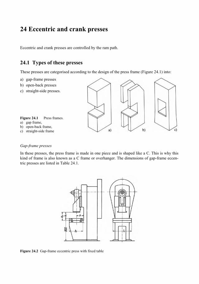
24 Eccentric and crank presses
Eccentric and crank presses are controlled by the ram path.
24.1 Types of these presses These presses are categorised according to the design of the press frame (Figure 24.1) into:
a) gap-frame presses b) open-back presses c) straight-side presses.
Figure 24.1 Press frames. a) gap frame, b) open-back frame, c) straight-side frame
Gap-frame presses
In these presses, the press frame is made in one piece and is shaped like a C. This is why this kind of frame is also known as a C frame or overhanger. The dimensions of gap-frame eccen-tric presses are listed in Table 24.1.
Figure 24.2 Gap-frame eccentric press with fixed table

296 24 Eccentric and crank presses
Tab
le 2
4.1
Dim
ensi
ons o
f gap
-fra
me
ecce
ntric
pre
sses
Dim
ensi
ons
Pre
ss fo
rce
in k
N
100
160
250
400
630
1000
1600
2500
4000
Thro
at (g
ap)
a16
018
020
028
022
031
525
035
528
0
400
315
450
355
500
400
560
A
rea
wid
th ·
leng
th
w
1 · l 1
315
400
355
450
400
500
560
710
450
560
630
800
500
630
710
900
560
80
071
0 1
000
630
800
900
1120
710
900
1000
1250
800
1000
1120
1400
with
bol
ster
pla
te e
113
515
017
516
020
018
023
019
026
5
215
300
275
325
310
360
340
Plat
en
Dis
tanc
e fr
om ra
m
with
out b
olst
er p
late
e 2
200
220
250
280
315
355
400
450
500
8 –
112
2
0 –
120
32
– 13
2 4
0 –
140
Stro
ke a
djus
tmen
t ran
ge fr
om
to
6 –
60
8 –
68
8 –
80
8 –
88
8 –
100
20 –
140
2
0 –
160
32
– 20
0 4
0 –
220
Ram
Hei
ght a
djus
tmen
t M
inim
um
4050
5063
6380
100
125
160
All
mea
sure
men
ts in
mm
Tab
le 2
3.2
Dim
ensi
ons o
f ope
n-ba
ck e
ccen
tric
pres
ses
Dim
ensi
ons
Pre
ss fo
rce
in k
N
160
250
400
630
1000
1600
2500
4000
Thro
at (g
ap)
180
200
220
250
280
400
315
450
355
500
400
560
Plat
en
Are
aw
idth
· le
ngth
w1 ·
l 135
550
040
056
045
063
050
071
056
080
0 8
0010
0063
090
0 9
0011
20 7
1010
0010
0012
50 8
0011
2011
2014
00D
ista
nce
from
ram
w
ithou
t bol
ster
pla
te
e 222
025
028
031
535
540
045
050
0
8 –
112
2
0 –
120
32
– 13
2 4
0 –
140
Stro
ke a
djus
tmen
t ran
ge fr
om
to
8 –
68
8 –
80
8 –
88
8 –
100
20 –
140
2
0 –
160
32
– 20
0 4
0 –
220
Ram
Hei
ght a
djus
tmen
t M
inim
um
5050
6363
8010
012
516
0
All
mea
sure
men
ts in
mm
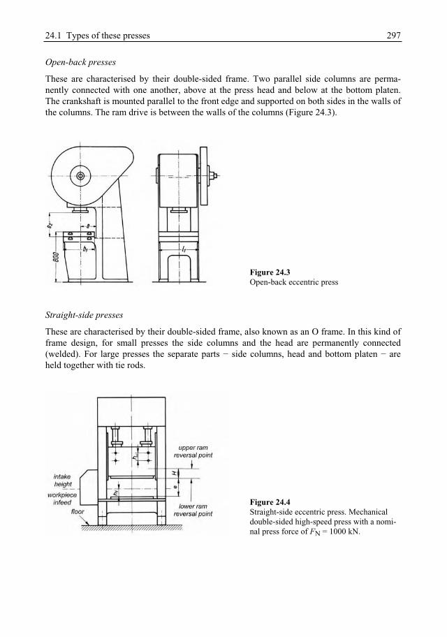
24.1 Types of these presses 297
Open-back presses
These are characterised by their double-sided frame. Two parallel side columns are perma-nently connected with one another, above at the press head and below at the bottom platen. The crankshaft is mounted parallel to the front edge and supported on both sides in the walls of the columns. The ram drive is between the walls of the columns (Figure 24.3).
Figure 24.3 Open-back eccentric press
Straight-side presses
These are characterised by their double-sided frame, also known as an O frame. In this kind of frame design, for small presses the side columns and the head are permanently connected (welded). For large presses the separate parts side columns, head and bottom platen are held together with tie rods.
Figure 24.4Straight-side eccentric press. Mechanical double-sided high-speed press with a nomi-nal press force of FN = 1000 kN.
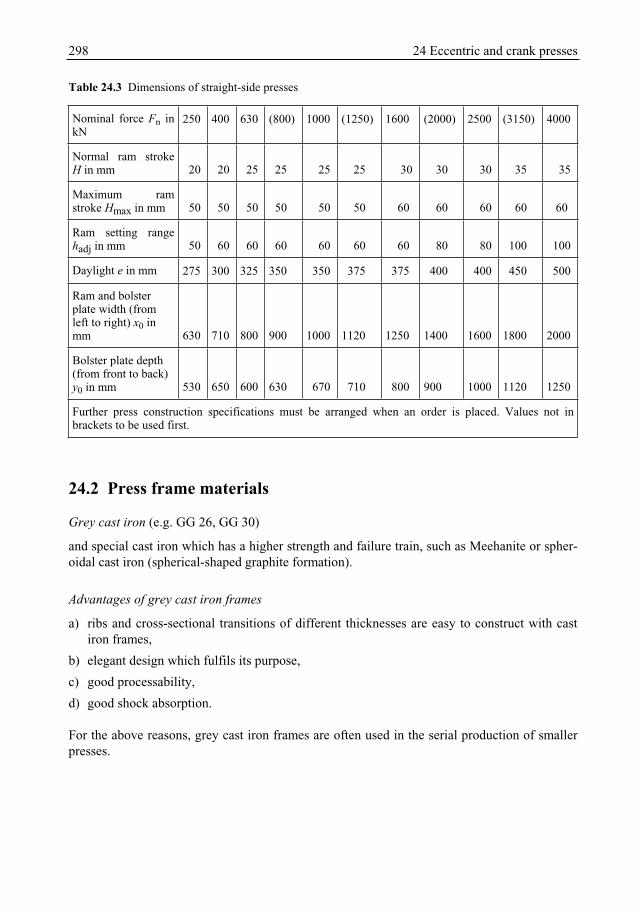
298 24 Eccentric and crank presses
Table 24.3 Dimensions of straight-side presses
Nominal force Fn inkN
250 400 630 (800) 1000 (1250) 1600 (2000) 2500 (3150) 4000
Normal ram stroke H in mm 20 20 25 25 25 25 30 30 30 35 35
Maximum ram stroke Hmax in mm 50 50 50 50 50 50 60 60 60 60 60
Ram setting range hadj in mm 50 60 60 60 60 60 60 80 80 100 100
Daylight e in mm 275 300 325 350 350 375 375 400 400 450 500
Ram and bolster plate width (from left to right) x0 inmm 630 710 800 900 1000 1120 1250 1400 1600 1800 2000
Bolster plate depth (from front to back) y0 in mm 530 650 600 630 670 710 800 900 1000 1120 1250
Further press construction specifications must be arranged when an order is placed. Values not in brackets to be used first.
24.2 Press frame materials
Grey cast iron (e.g. GG 26, GG 30)
and special cast iron which has a higher strength and failure train, such as Meehanite or spher-oidal cast iron (spherical-shaped graphite formation).
Advantages of grey cast iron frames
a) ribs and cross-sectional transitions of different thicknesses are easy to construct with cast iron frames,
b) elegant design which fulfils its purpose, c) good processability, d) good shock absorption.
For the above reasons, grey cast iron frames are often used in the serial production of smaller presses.

24.3 Frame deflection and deflection energy 299
Disadvantages of grey cast iron frames
The lower strength of cast iron frames means they have larger cross sections and thus larger masses than steel frames.
Cast steel (e.g. GS 45, GS 52)
is used most often in presses with a higher ultimate power which can easily be overloaded (forging presses) because of its good malleability and weldability, higher strength and failure strain.
Steel (e.g. constructional steel St 42)
is used with frames built in a framework or steel-plate design. The advantages of steel con-struction over a cast iron design are: a) higher modulus of elasticity, b) higher strength, c) due to a) and b), smaller cross-sections and lighter frames, d) no pattern costs, meaning that steel constructions are commonly used for single-part and
small lot production.
The disadvantages of a steel construction is the poor shock absorption and the complex stress-relief annealing which has to be carried out after welding.
24.3 Frame deflection and deflection energy
On every stroke, the press frame must absorb deflection energy Wd. When the press force Frises, the press frame stretches by the frame deflection f, thus acquiring a potential energy of
4d 31 5 10 m/ mm2 10 mm /m
F fW F f
Wd in Nm potential energy F in N press force f in mm frame deflection.
The resistance to deflection C of a press frame is defined as
FCf
C in kN/mm resistance to deflection F in kN press force f in mm frame deflection.
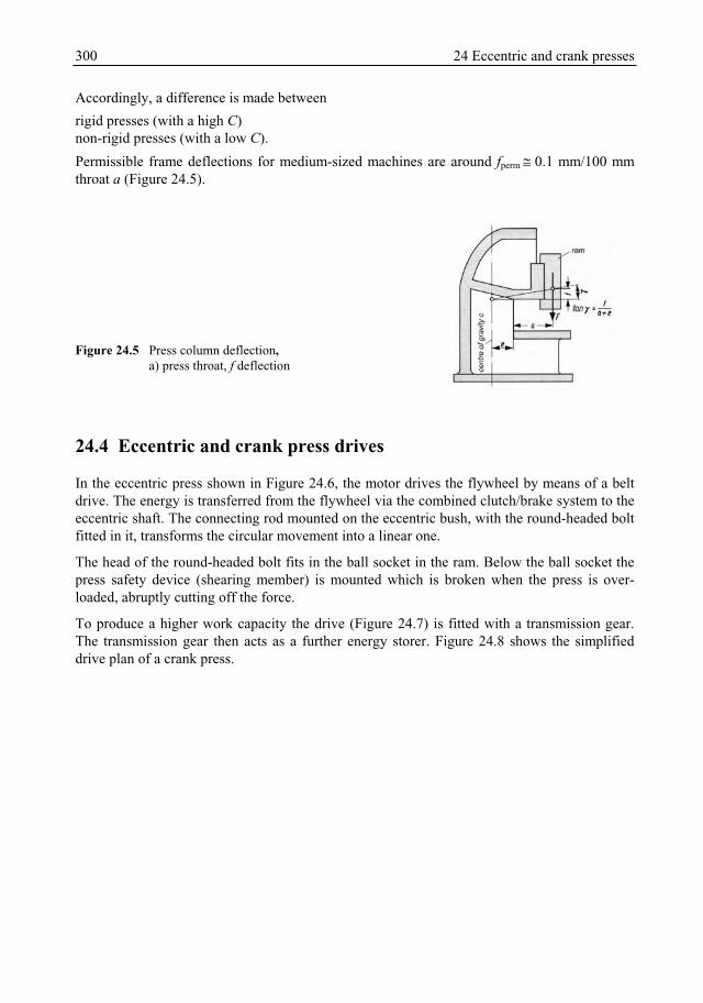
300 24 Eccentric and crank presses
Accordingly, a difference is made between rigid presses (with a high C)non-rigid presses (with a low C).Permissible frame deflections for medium-sized machines are around fperm 0.1 mm/100 mm throat a (Figure 24.5).
Figure 24.5 Press column deflection,a) press throat, f deflection
24.4 Eccentric and crank press drives
In the eccentric press shown in Figure 24.6, the motor drives the flywheel by means of a belt drive. The energy is transferred from the flywheel via the combined clutch/brake system to the eccentric shaft. The connecting rod mounted on the eccentric bush, with the round-headed bolt fitted in it, transforms the circular movement into a linear one.
The head of the round-headed bolt fits in the ball socket in the ram. Below the ball socket the press safety device (shearing member) is mounted which is broken when the press is over-loaded, abruptly cutting off the force.
To produce a higher work capacity the drive (Figure 24.7) is fitted with a transmission gear. The transmission gear then acts as a further energy storer. Figure 24.8 shows the simplified drive plan of a crank press.
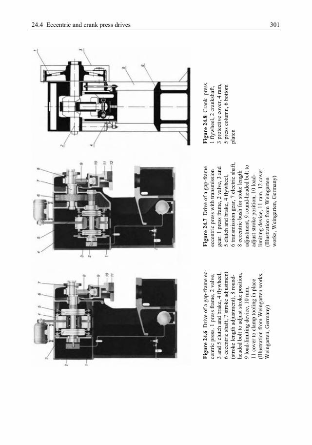
24.4 Eccentric and crank press drives 301
Figu
re 2
4.8
Cra
nk p
ress
.1
flyw
heel
, 2 c
rank
shaf
t,3
prot
ectiv
e co
ver,
4 ra
m,
5 pr
ess c
olum
n, 6
bot
tom
plat
en
Figu
re 2
4.7
Driv
e of
a g
ap-f
ram
e ec
cent
ric p
ress
with
tran
smis
sion
ge
ar. 1
pre
ss fr
ame,
2 v
alve
, 3 a
nd
5 cl
utch
and
bra
ke, 4
flyw
heel
,6
trans
mis
sion
gea
r, 7
elec
tric
shaf
t, 8
ecce
ntric
bus
h fo
r sto
ke le
ngth
ad
just
men
t, 9
roun
d-he
aded
bol
t to
adju
st st
roke
pos
ition
, 10
load
-lim
iting
dev
ice,
11
ram
, 12
cove
r (I
llust
ratio
n fr
om W
eing
arte
n w
orks
, Wei
ngar
ten,
Ger
man
y)
Figu
re 2
4.6
Driv
e of
a g
ap-f
ram
e ec
-ce
ntric
pre
ss. 1
pre
ss fr
ame,
2 v
alve
, 3
and
5 cl
utch
and
bra
ke, 4
flyw
heel
,6
ecce
ntric
shaf
t, 7
stro
ke a
djus
tmen
t (s
troke
leng
th a
djus
tmen
t), 8
roun
d-he
aded
bol
t to
adju
st st
roke
pos
ition
,9
load
-lim
iting
dev
ice,
10
ram
,11
cov
er to
cla
mp
tool
ing
in p
lace
(I
llust
ratio
n fr
om W
eing
arte
n w
orks
, W
eing
arte
n, G
erm
any)
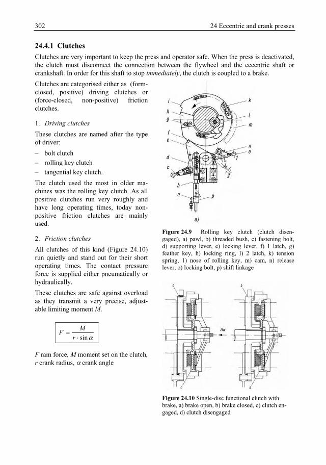
302 24 Eccentric and crank presses
24.4.1 Clutches Clutches are very important to keep the press and operator safe. When the press is deactivated, the clutch must disconnect the connection between the flywheel and the eccentric shaft or crankshaft. In order for this shaft to stop immediately, the clutch is coupled to a brake. Clutches are categorised either as (form-closed, positive) driving clutches or (force-closed, non-positive) friction clutches.
1. Driving clutches These clutches are named after the type of driver: – bolt clutch – rolling key clutch – tangential key clutch. The clutch used the most in older ma-chines was the rolling key clutch. As all positive clutches run very roughly and have long operating times, today non-positive friction clutches are mainly used.
2. Friction clutchesAll clutches of this kind (Figure 24.10) run quietly and stand out for their short operating times. The contact pressure force is supplied either pneumatically or hydraulically. These clutches are safe against overload as they transmit a very precise, adjust-able limiting moment M.
sinMF
r
F ram force, M moment set on the clutch,r crank radius, crank angle
Figure 24.9 Rolling key clutch (clutch disen-gaged), a) pawl, b) threaded bush, c) fastening bolt, d) supporting lever, e) locking lever, f) 1 latch, g) feather key, h) locking ring, I) 2 latch, k) tension spring, 1) nose of rolling key, m) cam, n) release lever, o) locking bolt, p) shift linkage
Figure 24.10 Single-disc functional clutch with brake, a) brake open, b) brake closed, c) clutch en-gaged, d) clutch disengaged
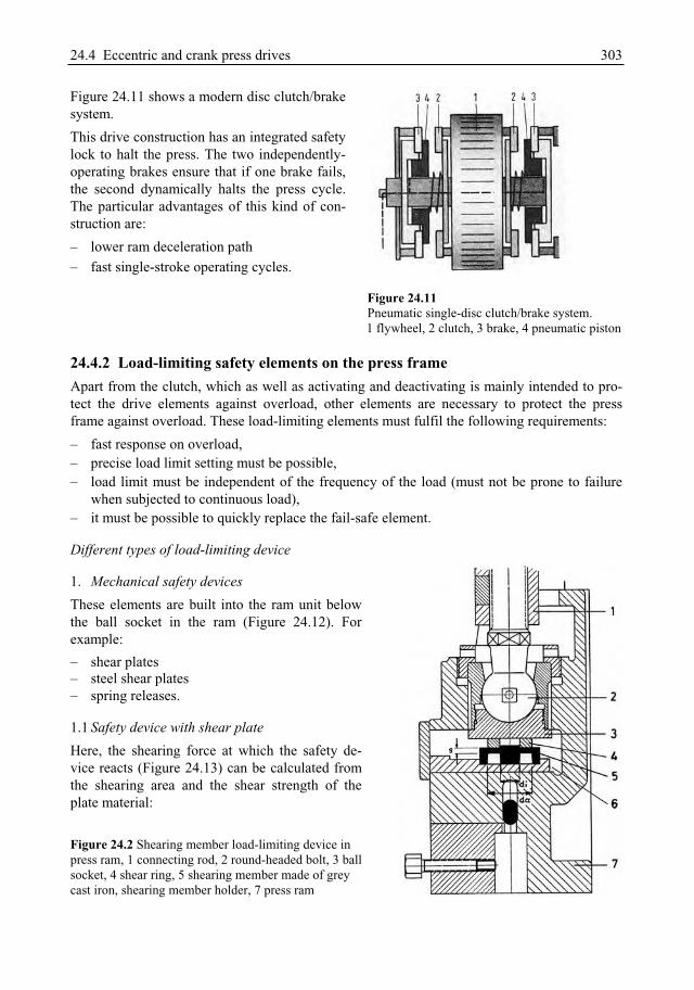
24.4 Eccentric and crank press drives 303
Figure 24.11 shows a modern disc clutch/brake system. This drive construction has an integrated safety lock to halt the press. The two independently-operating brakes ensure that if one brake fails, the second dynamically halts the press cycle. The particular advantages of this kind of con-struction are: – lower ram deceleration path – fast single-stroke operating cycles.
Figure 24.11 Pneumatic single-disc clutch/brake system. 1 flywheel, 2 clutch, 3 brake, 4 pneumatic piston
24.4.2 Load-limiting safety elements on the press frame Apart from the clutch, which as well as activating and deactivating is mainly intended to pro-tect the drive elements against overload, other elements are necessary to protect the press frame against overload. These load-limiting elements must fulfil the following requirements: – fast response on overload, – precise load limit setting must be possible, – load limit must be independent of the frequency of the load (must not be prone to failure
when subjected to continuous load), – it must be possible to quickly replace the fail-safe element.
Different types of load-limiting device
1. Mechanical safety devicesThese elements are built into the ram unit below the ball socket in the ram (Figure 24.12). For example: – shear plates – steel shear plates – spring releases.
1.1 Safety device with shear plateHere, the shearing force at which the safety de-vice reacts (Figure 24.13) can be calculated from the shearing area and the shear strength of the plate material:
Figure 24.2 Shearing member load-limiting device in press ram, 1 connecting rod, 2 round-headed bolt, 3 ball socket, 4 shear ring, 5 shearing member made of grey cast iron, shearing member holder, 7 press ram
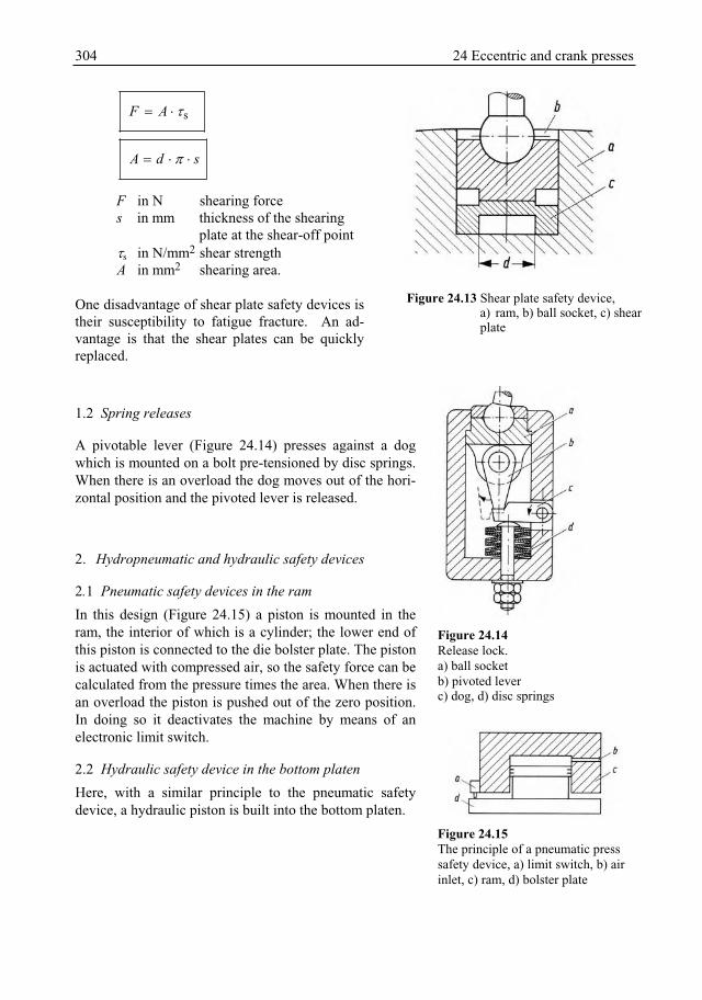
304 24 Eccentric and crank presses
sF A
A d s
F in N shearing force s in mm thickness of the shearing
plate at the shear-off point s in N/mm2 shear strength
A in mm2 shearing area.
One disadvantage of shear plate safety devices is their susceptibility to fatigue fracture. An ad-vantage is that the shear plates can be quickly replaced.
Figure 24.13 Shear plate safety device, a) ram, b) ball socket, c) shear plate
1.2 Spring releases
A pivotable lever (Figure 24.14) presses against a dog which is mounted on a bolt pre-tensioned by disc springs. When there is an overload the dog moves out of the hori-zontal position and the pivoted lever is released.
2. Hydropneumatic and hydraulic safety devices
2.1 Pneumatic safety devices in the ramIn this design (Figure 24.15) a piston is mounted in the ram, the interior of which is a cylinder; the lower end of this piston is connected to the die bolster plate. The piston is actuated with compressed air, so the safety force can be calculated from the pressure times the area. When there is an overload the piston is pushed out of the zero position. In doing so it deactivates the machine by means of an electronic limit switch.
2.2 Hydraulic safety device in the bottom platenHere, with a similar principle to the pneumatic safety device, a hydraulic piston is built into the bottom platen.
Figure 24.14Release lock. a) ball socket b) pivoted lever c) dog, d) disc springs
Figure 24.15The principle of a pneumatic press safety device, a) limit switch, b) air inlet, c) ram, d) bolster plate
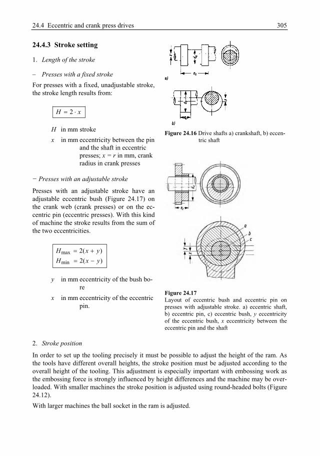
24.4 Eccentric and crank press drives 305
Figure 24.16 Drive shafts a) crankshaft, b) eccen-tric shaft
24.4.3 Stroke setting
1. Length of the stroke
– Presses with a fixed strokeFor presses with a fixed, unadjustable stroke, the stroke length results from:
2H x
H in mm stroke x in mm eccentricity between the pin
and the shaft in eccentric presses; x = r in mm, crank radius in crank presses
Presses with an adjustable stroke
Presses with an adjustable stroke have an adjustable eccentric bush (Figure 24.17) on the crank web (crank presses) or on the ec-centric pin (eccentric presses). With this kind of machine the stroke results from the sum of the two eccentricities.
max
min
2( )2( )
H x yH x y
y in mm eccentricity of the bush bo-re
x in mm eccentricity of the eccentric pin.
Figure 24.17Layout of eccentric bush and eccentric pin on presses with adjustable stroke. a) eccentric shaft, b) eccentric pin, c) eccentric bush, y eccentricity of the eccentric bush, x eccentricity between the eccentric pin and the shaft
2. Stroke position
In order to set up the tooling precisely it must be possible to adjust the height of the ram. As the tools have different overall heights, the stroke position must be adjusted according to the overall height of the tooling. This adjustment is especially important with embossing work as the embossing force is strongly influenced by height differences and the machine may be over-loaded. With smaller machines the stroke position is adjusted using round-headed bolts (Figure 24.12).With larger machines the ball socket in the ram is adjusted.

306 24 Eccentric and crank presses
24.5 Calculating the parameters
24.5.1 Clutch moment
def M9554 PMn
def(360 )P P
in deg. crank angle M in Nm moment n in min–1 strokes per minute P in kW motor power Pdef in kW short-term capacity available for forming between and BDC
in deg. angle at which the energy is released until BDC M – press efficiency.
Because the energy stored in the flywheel is released between and the BDC (bottom dead centre), in this range a short-term power of Pdef is available.
24.5.2 Tangential force
– Dynamic tangential force
The dynamic tangential force results from:
def d c
defd
c
30
30
nP M T r
PTr n
Td in N dynamic tangential force T in N static tangential force rk in m effective radius on the clutch.
Static tangential force
The static tangential force results from:
c
30PTr n
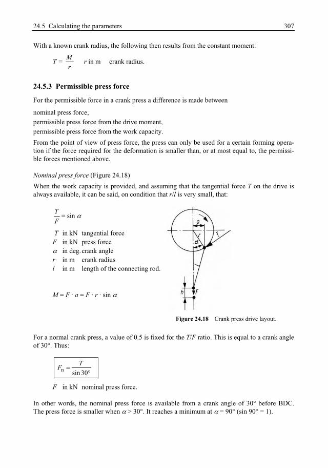
24.5 Calculating the parameters 307
With a known crank radius, the following then results from the constant moment:
T = Mr
r in m crank radius.
24.5.3 Permissible press force
For the permissible force in a crank press a difference is made between
nominal press force, permissible press force from the drive moment, permissible press force from the work capacity. From the point of view of press force, the press can only be used for a certain forming opera-tion if the force required for the deformation is smaller than, or at most equal to, the permissi-ble forces mentioned above.
Nominal press force (Figure 24.18) When the work capacity is provided, and assuming that the tangential force T on the drive is always available, it can be said, on condition that r/l is very small, that:
TF
= sin
T in kN tangential force F in kN press force
in deg. crank angle r in m crank radius l in m length of the connecting rod.
M = F · a = F · r · sin
Figure 24.18 Crank press drive layout.
For a normal crank press, a value of 0.5 is fixed for the T/F ratio. This is equal to a crank angle of 30°. Thus:
n sin 30TF
F in kN nominal press force.
In other words, the nominal press force is available from a crank angle of 30° before BDC. The press force is smaller when > 30°. It reaches a minimum at = 90° (sin 90° = 1).
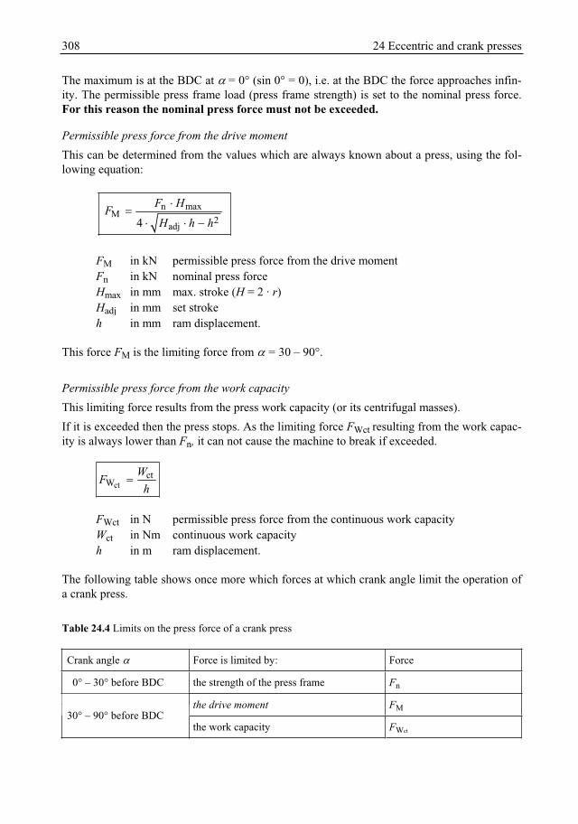
308 24 Eccentric and crank presses
The maximum is at the BDC at = 0° (sin 0° = 0), i.e. at the BDC the force approaches infin-ity. The permissible press frame load (press frame strength) is set to the nominal press force. For this reason the nominal press force must not be exceeded.
Permissible press force from the drive momentThis can be determined from the values which are always known about a press, using the fol-lowing equation:
n maxM 2adj4
F HFH h h
FM in kN permissible press force from the drive moment Fn in kN nominal press force Hmax in mm max. stroke (H = 2 · r)Hadj in mm set stroke h in mm ram displacement.
This force FM is the limiting force from = 30 – 90°.
Permissible press force from the work capacityThis limiting force results from the press work capacity (or its centrifugal masses). If it is exceeded then the press stops. As the limiting force FWct resulting from the work capac-ity is always lower than Fn, it can not cause the machine to break if exceeded.
ctct
WWF
h
FWct in N permissible press force from the continuous work capacity Wct in Nm continuous work capacity h in m ram displacement.
The following table shows once more which forces at which crank angle limit the operation of a crank press.
Table 24.4 Limits on the press force of a crank press
Crank angle Force is limited by: Force
0° – 30° before BDC the strength of the press frame Fn
the drive moment FM30° – 90° before BDC
the work capacity FWct
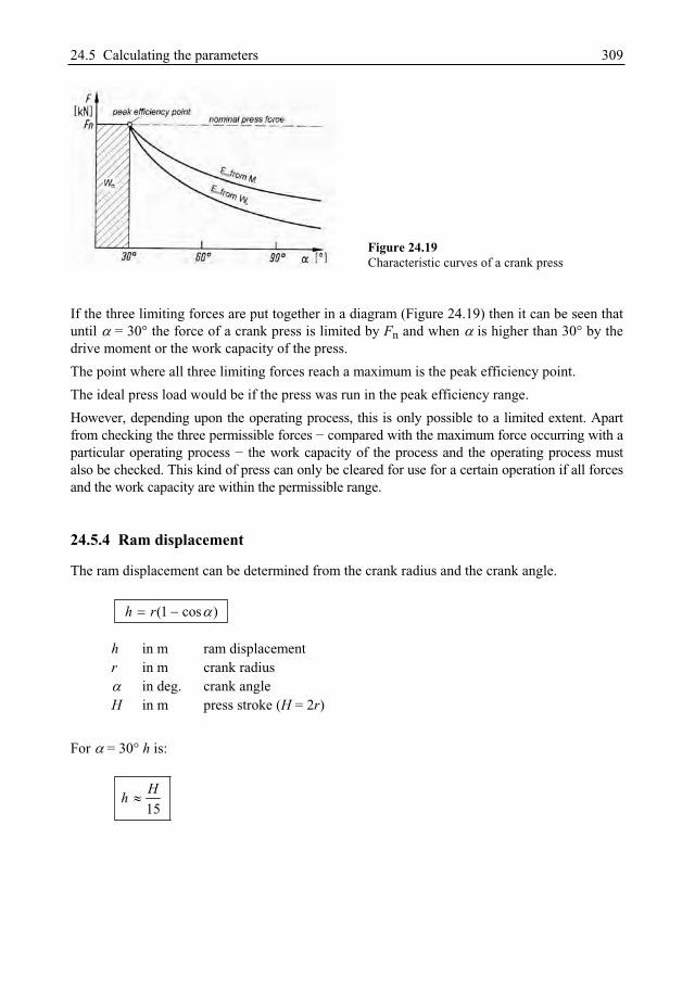
24.5 Calculating the parameters 309
Figure 24.19Characteristic curves of a crank press
If the three limiting forces are put together in a diagram (Figure 24.19) then it can be seen that until = 30° the force of a crank press is limited by Fn and when is higher than 30° by the drive moment or the work capacity of the press. The point where all three limiting forces reach a maximum is the peak efficiency point. The ideal press load would be if the press was run in the peak efficiency range.However, depending upon the operating process, this is only possible to a limited extent. Apart from checking the three permissible forces compared with the maximum force occurring with a particular operating process the work capacity of the process and the operating process must also be checked. This kind of press can only be cleared for use for a certain operation if all forces and the work capacity are within the permissible range.
24.5.4 Ram displacement
The ram displacement can be determined from the crank radius and the crank angle.
(1 cos )h r
h in m ram displacement r in m crank radius
in deg. crank angle H in m press stroke (H = 2r)
For = 30° h is:
15Hh

310 24 Eccentric and crank presses
24.5.5 Work capacity
1. Continuous work capacity
This means the work capacity of a press in continuous mode, i.e. if the press runs without interruption. The continuous mode requires an automatic material and workpiece feed system.
nct 15
F HW
Wct in Nm work capacity in continuous mode Wsi in Nm work capacity in single-stroke mode H in m press stroke (H = 2r) r in m crank radius Fn in N nominal press force.
2. Work capacity in single-stroke mode
si ct2W W
Single-stroke mode is when the press stops after every stroke and needs to be initiated again (clutch engaged). When workpieces need to be inserted by hand, presses are run in single-stroke mode. As the flywheel speed, which drops on the working stroke, can be fully recovered during the insertion period (unlike in automatic mode), the work capacity in single-stroke mode is around double that of continuous mode.
24.6 Example The following must be found for an extrusion: max. press force F = 1200 kN with a ram displacement of h = 20 mm.
A crank press is available with a nominal press force of Fn = 2000 kN and astroke of H = Hadj = 200 mm (not adjustable). Can the press be used for this operation?
Solution:
1. Determining the extrusion work
WF1 = F · h · x = 1200 kN · 20 mm · 1 = 24 000 kNmm

24.6 Example 311
2. Work capacity of the press in continuous mode Wct
nct
20 00 kN 200 mm 26 666.7 kN mm15 15
F HW
3. Comparison of both work capacities. The work capacity of the press in continuous mode, Wct, is higher than that required for the deformation, WF1
Wct > WF1
26 666.7 kN mm > 24 000 kN mm i.e. the press can be used for this operation in continuous mode.
4. Assessing the forces.
4.1. Nominal press force Fn
The nominal press force is higher than the force required for the deformation Fn > FF1
2000 kN > 1200 kN For this reason, the press can be used for this operation from the point of view of the nominal press force.
4.2. Determining the permissible press force FM from the drive moment
n maxM 2 2 2adj
2000 kN 200 mm 1 666.7 kN4 4 200 20mm 20 mm
F HFH h h
The permissible press force resulting from the drive moment and taking into account the stroke is higher than the extrusion force,
FM > FF1
1666.7 kN > 1200 kN meaning that the press can also be used from this point of view.
4.3. Determining the permissible press force from the continuous work capacity of the press
ctct
W26 666.7 kN 1333.3 kN
20mmWF
hFWct > FF1 so it can be used.
Decision: As the permissible forces and the continuous work capacity of the press are higher under the given conditions than the deformation forces and the work capacity required for the deformation, the press can be used.

312 24 Eccentric and crank presses
24.7 Application of eccentric and crank presses Eccentric pressesare mainly used for blanking, embossing and bending, as long as only small displacements are required, as the eccentric demands.
Crank pressesare used for all chipless forming methods where the deformation force does not have to be constant over a long distance, i.e. for the forward extrusion of short components, deep draw-ing, bending and impression-die forging on heavy forging presses.
24.8 Exercise on Chapter 24 1. What kinds of frame construction are there for eccentric and crank presses? 2. Why is the press frame’s resistance to deflection of great importance? 3. What kinds of drive are there for eccentric and crank presses? 4. What kinds of clutches are there for crank presses? 5. What load-limiting safety devices do you know? 6. How is the ram stroke length adjusted on an eccentric press? 7. How is an eccentric press protected against overload? 8. What different types of eccentric and crank press construction are there?
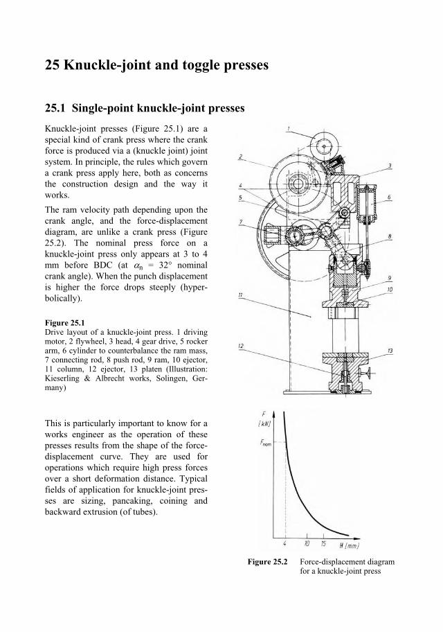
25 Knuckle-joint and toggle presses
25.1 Single-point knuckle-joint presses Knuckle-joint presses (Figure 25.1) are a special kind of crank press where the crank force is produced via a (knuckle joint) joint system. In principle, the rules which govern a crank press apply here, both as concerns the construction design and the way it works.The ram velocity path depending upon the crank angle, and the force-displacement diagram, are unlike a crank press (Figure 25.2). The nominal press force on a knuckle-joint press only appears at 3 to 4 mm before BDC (at n = 32° nominal crank angle). When the punch displacement is higher the force drops steeply (hyper-bolically).
Figure 25.1Drive layout of a knuckle-joint press. 1 driving motor, 2 flywheel, 3 head, 4 gear drive, 5 rocker arm, 6 cylinder to counterbalance the ram mass, 7 connecting rod, 8 push rod, 9 ram, 10 ejector, 11 column, 12 ejector, 13 platen (Illustration: Kieserling & Albrecht works, Solingen, Ger-many)
This is particularly important to know for a works engineer as the operation of these presses results from the shape of the force-displacement curve. They are used for operations which require high press forces over a short deformation distance. Typical fields of application for knuckle-joint pres-ses are sizing, pancaking, coining and backward extrusion (of tubes).
Figure 25.2 Force-displacement diagram for a knuckle-joint press
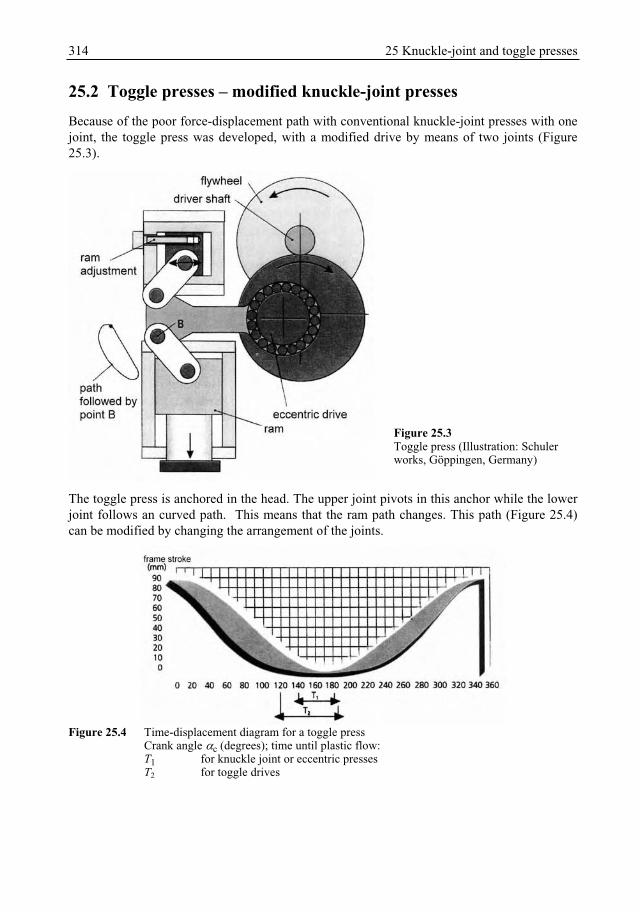
314 25 Knuckle-joint and toggle presses
25.2 Toggle presses – modified knuckle-joint presses Because of the poor force-displacement path with conventional knuckle-joint presses with one joint, the toggle press was developed, with a modified drive by means of two joints (Figure 25.3).
Figure 25.3Toggle press (Illustration: Schuler works, Göppingen, Germany)
The toggle press is anchored in the head. The upper joint pivots in this anchor while the lower joint follows an curved path. This means that the ram path changes. This path (Figure 25.4) can be modified by changing the arrangement of the joints.
Figure 25.4 Time-displacement diagram for a toggle press Crank angle c (degrees); time until plastic flow: T1 for knuckle joint or eccentric pressesT2 for toggle drives
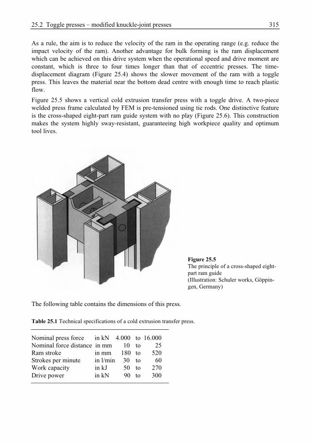
25.2 Toggle presses – modified knuckle-joint presses 315
As a rule, the aim is to reduce the velocity of the ram in the operating range (e.g. reduce the impact velocity of the ram). Another advantage for bulk forming is the ram displacement which can be achieved on this drive system when the operational speed and drive moment are constant, which is three to four times longer than that of eccentric presses. The time-displacement diagram (Figure 25.4) shows the slower movement of the ram with a toggle press. This leaves the material near the bottom dead centre with enough time to reach plastic flow.Figure 25.5 shows a vertical cold extrusion transfer press with a toggle drive. A two-piece welded press frame calculated by FEM is pre-tensioned using tie rods. One distinctive feature is the cross-shaped eight-part ram guide system with no play (Figure 25.6). This construction makes the system highly sway-resistant, guaranteeing high workpiece quality and optimum tool lives.
Figure 25.5The principle of a cross-shaped eight-part ram guide(Illustration: Schuler works, Göppin-gen, Germany)
The following table contains the dimensions of this press.
Table 25.1 Technical specifications of a cold extrusion transfer press.
Nominal press force in kN 4.000 to 16.000 Nominal force distance in mm 10 to 25 Ram stroke in mm 180 to 520 Strokes per minute in l/min 30 to 60 Work capacity in kJ 50 to 270 Drive power in kN 90 to 300
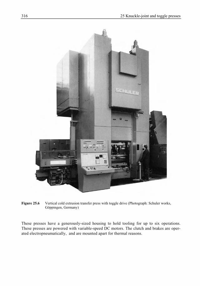
316 25 Knuckle-joint and toggle presses
Figure 25.6 Vertical cold extrusion transfer press with toggle drive (Photograph: Schuler works, Göppingen, Germany)
These presses have a generously-sized housing to hold tooling for up to six operations. These presses are powered with variable-speed DC motors. The clutch and brakes are oper-ated electropneumatically, and are mounted apart for thermal reasons.
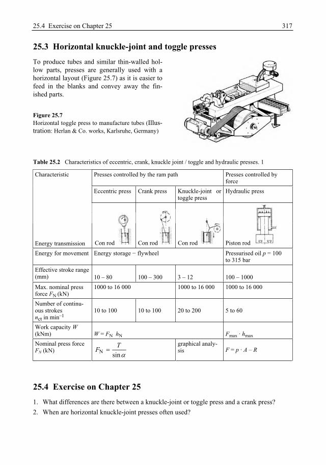
25.4 Exercise on Chapter 25 317
25.3 Horizontal knuckle-joint and toggle presses To produce tubes and similar thin-walled hol-low parts, presses are generally used with a horizontal layout (Figure 25.7) as it is easier to feed in the blanks and convey away the fin-ished parts.
Figure 25.7 Horizontal toggle press to manufacture tubes (Illus-tration: Herlan & Co. works, Karlsruhe, Germany)
Table 25.2 Characteristics of eccentric, crank, knuckle joint / toggle and hydraulic presses. 1
Presses controlled by the ram path Presses controlled by force
Eccentric press Crank press Knuckle-joint or toggle press
Hydraulic press
Characteristic
Energy transmission Con rod Con rod Con rod Piston rod
Energy for movement Energy storage flywheel Pressurised oil p = 100 to 315 bar
Effective stroke range (mm) 10 – 80 100 – 300 3 – 12 100 – 1000 Max. nominal press force FN (kN)
1000 to 16 000 1000 to 16 000 1000 to 16 000
Number of continu-ous strokes nct in min–1
10 to 100 10 to 100 20 to 200 5 to 60
Work capacity W(kNm) W = FN hN Fmax · hmax
Nominal press force FN (kN) N sin
TFgraphical analy-sis F = p · A – R
25.4 Exercise on Chapter 25 1. What differences are there between a knuckle-joint or toggle press and a crank press? 2. When are horizontal knuckle-joint presses often used?

26 Hydraulic presses
The frames of hydraulic presses are mainly built as welded steel O-frames (straight-side fra-mes) (Figure 26.1). In smaller presses the frame is built in one piece and in larger presses in three pieces. The three main elements (bottom platen, side columns and head) are held together with tie rods.
26.1 Hydraulic press drives The ram movement (Figure 26.2) is produced by a differential piston. In small presses, the required amount of compressed oil is provided by means of constant feed pumps (gear or screw pumps) and in larger presses by adjustable axial or radial piston pumps. The operating pressure for hydraulic presses is between 200 and 300 bar. Too low a pressure would require an oversized piston and too high a pressure would mean leakage would be hard to control. The most important technical data can be determined as follows:
Figure 26.1 Three-part hydraulic press. 1 head, 2 pump, 3 side column, 4 press cylinder, 5 ram, 6 guide, 7 cross-section of side col-umn, 8 tie rod, 9 bottom platen (Illustra-tion from LASCO Umformtechnik works, Coburg, Germany)
Figure 26.2 Highly simplified drive layout ofa hydraulic press

26.1 Hydraulic press drives 319
1. Drive power:
QP = QPth · Pvol
QP in l/min actual pump capacity QPth in l/min theoretical pump capacity P in kW drive power p in bar pressure in the system QPvol – volumetric efficiency of the
pump Pm – mechanical efficiency of the
pump M – machine (press) efficiency
th
Pm M600Q pP
2. Piston speeds:
2.1 Forward stroke (working stroke):
QP = Qpi
Api in cm2 piston area during working stro-ke
d1 in cm diameter of the piston d2 in cm diameter of the differential pis-
ton
volp piA
pi1
21
pi1
10
4
Qv
A
dA
Qpi in l/min actual piston inward oil flow Qp in l/min actual pump outflow
ws in m/min speed of piston on forward stroke R in m/min speed of piston on return stroke pivol – volumetric efficiency of piston
2.2 Return stroke:
volp piR
pi2
2 2pi2 1 2
10
( )4
Qv
A
A d d
Api2 in cm2 piston area on return stroke Figure 26.3 Hydraulic cylinder with dif-ferential piston

320 26 Hydraulic presses
3. Piston force (without considering piston own weight and friction)
3.1 Press force (working stroke)
pi1210
p AF
F in kN press force p in bar operating pressure (as N/cm2)
3.2 Ram retraction force
pi2R 210
p AF
FR in kN retraction force.
26.2 Example A constant feed pump providing a feed flow of Qp = 200 l /min at an operating pressure of p = 150 bar is to be used to power a small hydraulic press.
Where: diameter of the working piston d1 = 200 mm; diameter of the differential piston d2 = 160 mm; pivol = 0.97
Find:
1. press force2. retraction force
without considering own weight and friction
3. speed of piston on forward stroke (operating speed) 4. speed on return stroke.
Solution:
1.2pi1
def 2 2 2150 daN (20 cm) 471.2 kN
10 N/ kN cm 10 N/ kN 4p A
F
2.2 2 2 2 2 21 2
R 2 2 2( ) 150 daN (20 cm 16 cm ) 159 kN10 4 cm 10 4
p d dF
3. volp piA 2 2pi1
10 200 l 10 0.97 6.17 m/ minmin 20 cm / 4
Qv
A
4. p pivolR 2 2 2 2pi2
10 200 l 10 0.97 17.1 m/ minmin (20 cm 16 cm ) / 4
Qv
A.
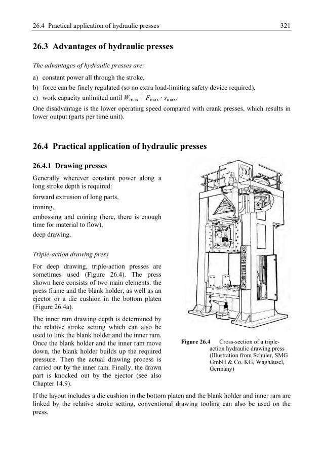
26.4 Practical application of hydraulic presses 321
26.3 Advantages of hydraulic presses
The advantages of hydraulic presses are:
a) constant power all through the stroke, b) force can be finely regulated (so no extra load-limiting safety device required), c) work capacity unlimited until Wmax = Fmax · smax.One disadvantage is the lower operating speed compared with crank presses, which results in lower output (parts per time unit).
26.4 Practical application of hydraulic presses
26.4.1 Drawing presses Generally wherever constant power along a long stroke depth is required: forward extrusion of long parts, ironing, embossing and coining (here, there is enough time for material to flow), deep drawing.
Triple-action drawing press
For deep drawing, triple-action presses are sometimes used (Figure 26.4). The press shown here consists of two main elements: the press frame and the blank holder, as well as an ejector or a die cushion in the bottom platen (Figure 26.4a).
The inner ram drawing depth is determined by the relative stroke setting which can also be used to link the blank holder and the inner ram. Once the blank holder and the inner ram move down, the blank holder builds up the required pressure. Then the actual drawing process is carried out by the inner ram. Finally, the drawn part is knocked out by the ejector (see also Chapter 14.9).
Figure 26.4 Cross-section of a triple-action hydraulic drawing press (Illustration from Schuler, SMG GmbH & Co. KG, Waghäusel, Germany)
If the layout includes a die cushion in the bottom platen and the blank holder and inner ram are linked by the relative stroke setting, conventional drawing tooling can also be used on the press.
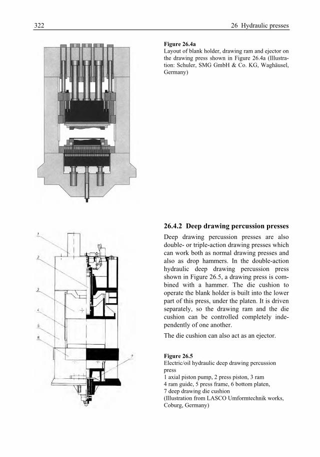
322 26 Hydraulic presses
Figure 26.4a Layout of blank holder, drawing ram and ejector on the drawing press shown in Figure 26.4a (Illustra-tion: Schuler, SMG GmbH & Co. KG, Waghäusel, Germany)
26.4.2 Deep drawing percussion presses Deep drawing percussion presses are also double- or triple-action drawing presses which can work both as normal drawing presses and also as drop hammers. In the double-action hydraulic deep drawing percussion press shown in Figure 26.5, a drawing press is com-bined with a hammer. The die cushion to operate the blank holder is built into the lower part of this press, under the platen. It is driven separately, so the drawing ram and the die cushion can be controlled completely inde-pendently of one another. The die cushion can also act as an ejector.
Figure 26.5 Electric/oil hydraulic deep drawing percussion press 1 axial piston pump, 2 press piston, 3 ram4 ram guide, 5 press frame, 6 bottom platen,7 deep drawing die cushion(Illustration from LASCO Umformtechnik works, Coburg, Germany)
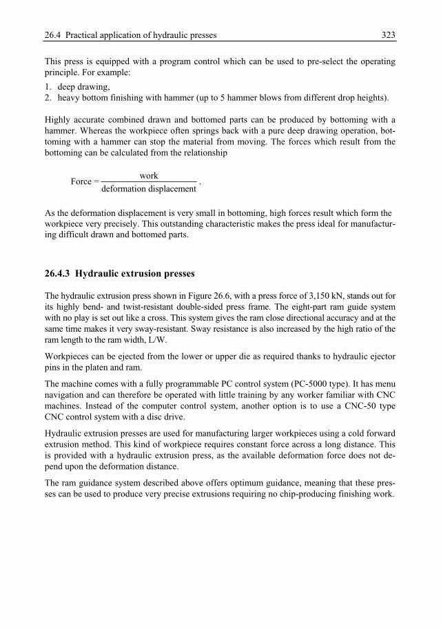
26.4 Practical application of hydraulic presses 323
This press is equipped with a program control which can be used to pre-select the operating principle. For example: 1. deep drawing, 2. heavy bottom finishing with hammer (up to 5 hammer blows from different drop heights).
Highly accurate combined drawn and bottomed parts can be produced by bottoming with a hammer. Whereas the workpiece often springs back with a pure deep drawing operation, bot-toming with a hammer can stop the material from moving. The forces which result from the bottoming can be calculated from the relationship
Force = workdeformation displacement
.
As the deformation displacement is very small in bottoming, high forces result which form the workpiece very precisely. This outstanding characteristic makes the press ideal for manufactur-ing difficult drawn and bottomed parts.
26.4.3 Hydraulic extrusion presses
The hydraulic extrusion press shown in Figure 26.6, with a press force of 3,150 kN, stands out for its highly bend- and twist-resistant double-sided press frame. The eight-part ram guide system with no play is set out like a cross. This system gives the ram close directional accuracy and at the same time makes it very sway-resistant. Sway resistance is also increased by the high ratio of the ram length to the ram width, L/W.
Workpieces can be ejected from the lower or upper die as required thanks to hydraulic ejector pins in the platen and ram.
The machine comes with a fully programmable PC control system (PC-5000 type). It has menu navigation and can therefore be operated with little training by any worker familiar with CNC machines. Instead of the computer control system, another option is to use a CNC-50 type CNC control system with a disc drive.
Hydraulic extrusion presses are used for manufacturing larger workpieces using a cold forward extrusion method. This kind of workpiece requires constant force across a long distance. This is provided with a hydraulic extrusion press, as the available deformation force does not de-pend upon the deformation distance.
The ram guidance system described above offers optimum guidance, meaning that these pres-ses can be used to produce very precise extrusions requiring no chip-producing finishing work.
324 26 Hydraulic presses
Figure 26.6 Hydraulic double-sided extrusion press (Photograph: Dunkes GmbH works, Kirchheim unter Teck, Germany)
26.5 Exercise on Chapter 26
1. Explain the drive layout of a hydraulic press. 2. How is the ram speed raised on the return stroke? 3. Why is high speed on the return stroke desirable? 4. What is the difference between a double-action and a single-action press? 5. What kind of operations are double-action or triple-action presses needed for?
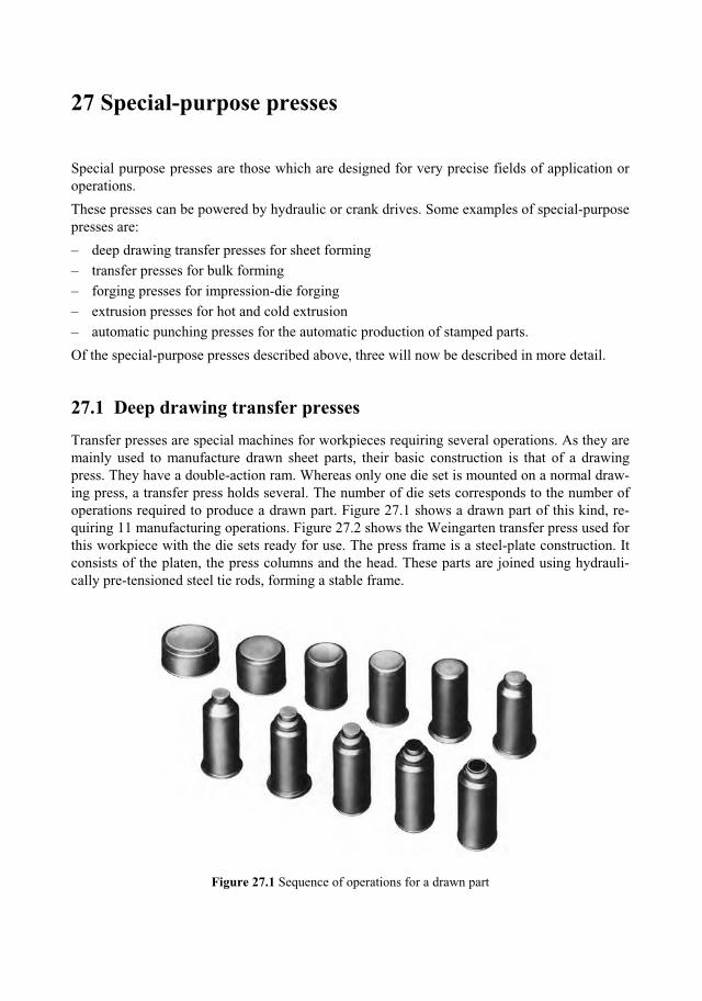
27 Special-purpose presses
Special purpose presses are those which are designed for very precise fields of application or operations. These presses can be powered by hydraulic or crank drives. Some examples of special-purpose presses are: – deep drawing transfer presses for sheet forming – transfer presses for bulk forming – forging presses for impression-die forging – extrusion presses for hot and cold extrusion – automatic punching presses for the automatic production of stamped parts. Of the special-purpose presses described above, three will now be described in more detail.
27.1 Deep drawing transfer presses Transfer presses are special machines for workpieces requiring several operations. As they are mainly used to manufacture drawn sheet parts, their basic construction is that of a drawing press. They have a double-action ram. Whereas only one die set is mounted on a normal draw-ing press, a transfer press holds several. The number of die sets corresponds to the number of operations required to produce a drawn part. Figure 27.1 shows a drawn part of this kind, re-quiring 11 manufacturing operations. Figure 27.2 shows the Weingarten transfer press used for this workpiece with the die sets ready for use. The press frame is a steel-plate construction. It consists of the platen, the press columns and the head. These parts are joined using hydrauli-cally pre-tensioned steel tie rods, forming a stable frame.
Figure 27.1 Sequence of operations for a drawn part
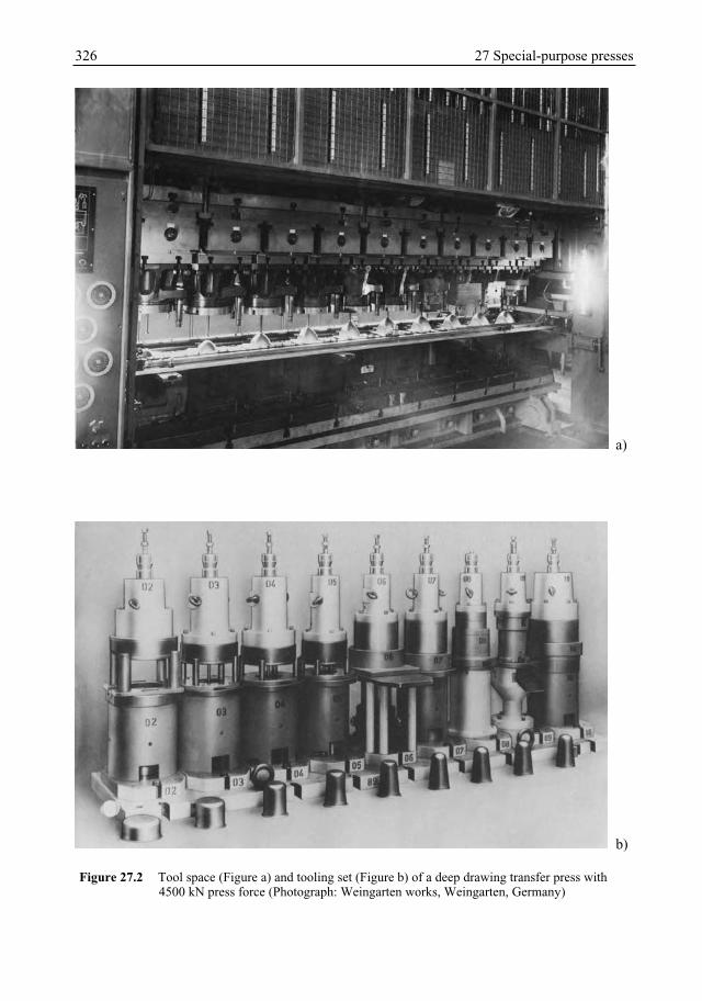
326 27 Special-purpose presses
a)
b)
Figure 27.2 Tool space (Figure a) and tooling set (Figure b) of a deep drawing transfer press with 4500 kN press force (Photograph: Weingarten works, Weingarten, Germany)
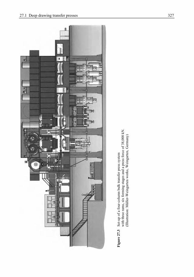
27.1 Deep drawing transfer presses 327
Figu
re 2
7.3
Set-u
p of
a fo
ur-c
olum
n bu
lk tr
ansf
er p
ress
syst
em
with
thre
e ra
ms,
six
form
ing
stag
es a
nd a
pre
ss fo
rce
of 3
8,00
0 kN
. (I
llust
ratio
n: M
ülle
r-W
eing
arte
n w
orks
, Wei
ngar
ten,
Ger
man
y)
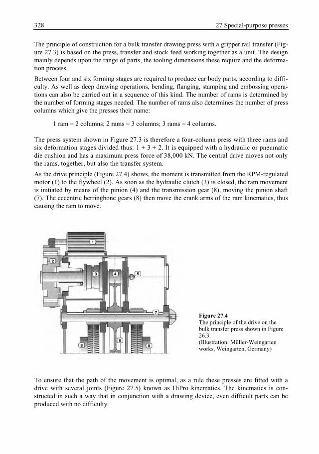
328 27 Special-purpose presses
The principle of construction for a bulk transfer drawing press with a gripper rail transfer (Fig-ure 27.3) is based on the press, transfer and stock feed working together as a unit. The design mainly depends upon the range of parts, the tooling dimensions these require and the deforma-tion process. Between four and six forming stages are required to produce car body parts, according to diffi-culty. As well as deep drawing operations, bending, flanging, stamping and embossing opera-tions can also be carried out in a sequence of this kind. The number of rams is determined by the number of forming stages needed. The number of rams also determines the number of press columns which give the presses their name:
1 ram = 2 columns; 2 rams = 3 columns; 3 rams = 4 columns.
The press system shown in Figure 27.3 is therefore a four-column press with three rams and six deformation stages divided thus: 1 + 3 + 2. It is equipped with a hydraulic or pneumatic die cushion and has a maximum press force of 38,000 kN. The central drive moves not only the rams, together, but also the transfer system. As the drive principle (Figure 27.4) shows, the moment is transmitted from the RPM-regulated motor (1) to the flywheel (2). As soon as the hydraulic clutch (3) is closed, the ram movement is initiated by means of the pinion (4) and the transmission gear (8), moving the pinion shaft (7). The eccentric herringbone gears (8) then move the crank arms of the ram kinematics, thus causing the ram to move.
Figure 27.4 The principle of the drive on the bulk transfer press shown in Figure 26.3.(Illustration: Müller-Weingarten works, Weingarten, Germany)
To ensure that the path of the movement is optimal, as a rule these presses are fitted with a drive with several joints (Figure 27.5) known as HiPro kinematics. The kinematics is con-structed in such a way that in conjunction with a drawing device, even difficult parts can be produced with no difficulty.
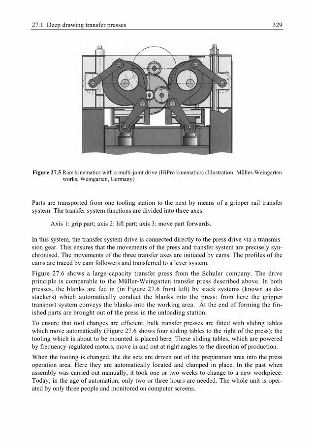
27.1 Deep drawing transfer presses 329
Figure 27.5 Ram kinematics with a multi-joint drive (HiPro kinematics) (Illustration: Müller-Weingarten works, Weingarten, Germany)
Parts are transported from one tooling station to the next by means of a gripper rail transfer system. The transfer system functions are divided into three axes.
Axis 1: grip part; axis 2: lift part; axis 3: move part forwards.
In this system, the transfer system drive is connected directly to the press drive via a transmis-sion gear. This ensures that the movements of the press and transfer system are precisely syn-chronised. The movements of the three transfer axes are initiated by cams. The profiles of the cams are traced by cam followers and transferred to a lever system. Figure 27.6 shows a large-capacity transfer press from the Schuler company. The drive principle is comparable to the Müller-Weingarten transfer press described above. In both presses, the blanks are fed in (in Figure 27.6 front left) by stack systems (known as de-stackers) which automatically conduct the blanks into the press: from here the gripper transport system conveys the blanks into the working area. At the end of forming the fin-ished parts are brought out of the press in the unloading station. To ensure that tool changes are efficient, bulk transfer presses are fitted with sliding tables which move automatically (Figure 27.6 shows four sliding tables to the right of the press); the tooling which is about to be mounted is placed here. These sliding tables, which are powered by frequency-regulated motors, move in and out at right angles to the direction of production. When the tooling is changed, the die sets are driven out of the preparation area into the press operation area. Here they are automatically located and clamped in place. In the past when assembly was carried out manually, it took one or two weeks to change to a new workpiece. Today, in the age of automation, only two or three hours are needed. The whole unit is oper-ated by only three people and monitored on computer screens.
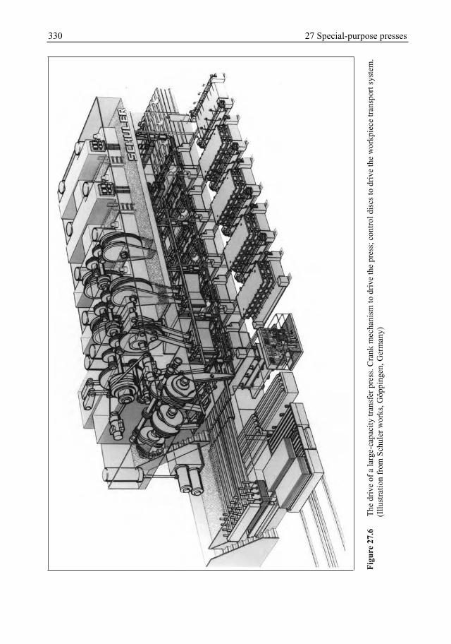
330 27 Special-purpose presses
Figu
re 2
7.6
The
driv
e of
a la
rge-
capa
city
tran
sfer
pre
ss. C
rank
mec
hani
sm to
driv
e th
e pr
ess;
con
trol d
iscs
to d
rive
the
wor
kpie
ce tr
ansp
o rt s
yste
m.
(Illu
stra
tion
from
Sch
uler
wor
ks, G
öppi
ngen
, Ger
man
y)
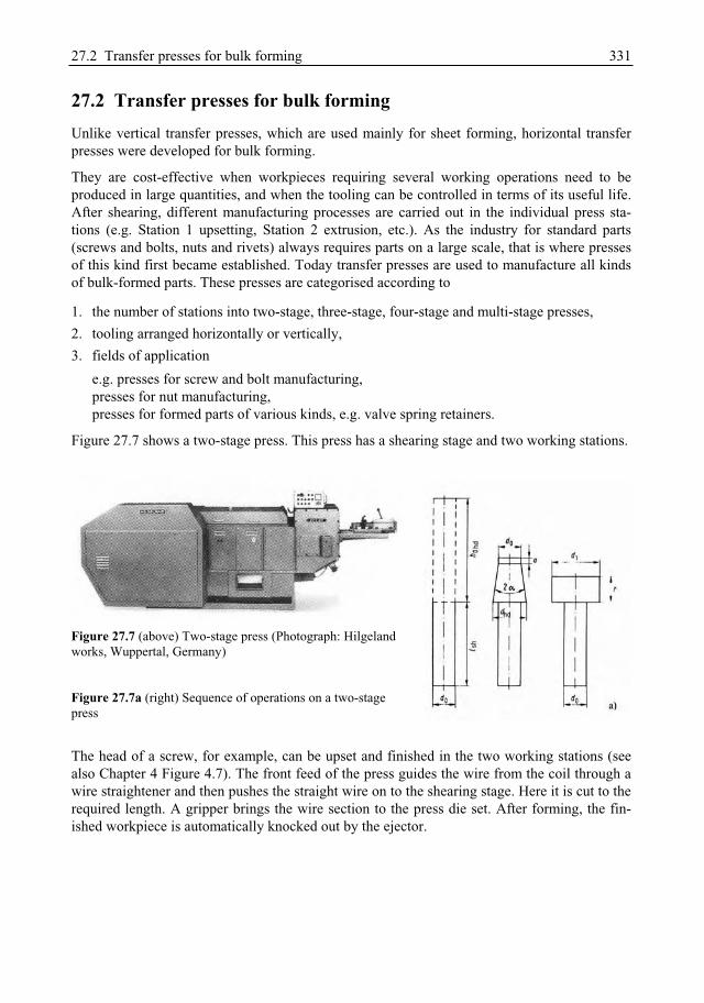
27.2 Transfer presses for bulk forming 331
27.2 Transfer presses for bulk forming Unlike vertical transfer presses, which are used mainly for sheet forming, horizontal transfer presses were developed for bulk forming.
They are cost-effective when workpieces requiring several working operations need to be produced in large quantities, and when the tooling can be controlled in terms of its useful life. After shearing, different manufacturing processes are carried out in the individual press sta-tions (e.g. Station 1 upsetting, Station 2 extrusion, etc.). As the industry for standard parts (screws and bolts, nuts and rivets) always requires parts on a large scale, that is where presses of this kind first became established. Today transfer presses are used to manufacture all kinds of bulk-formed parts. These presses are categorised according to
1. the number of stations into two-stage, three-stage, four-stage and multi-stage presses, 2. tooling arranged horizontally or vertically, 3. fields of application
e.g. presses for screw and bolt manufacturing, presses for nut manufacturing, presses for formed parts of various kinds, e.g. valve spring retainers.
Figure 27.7 shows a two-stage press. This press has a shearing stage and two working stations.
Figure 27.7 (above) Two-stage press (Photograph: Hilgeland works, Wuppertal, Germany)
Figure 27.7a (right) Sequence of operations on a two-stage press
The head of a screw, for example, can be upset and finished in the two working stations (see also Chapter 4 Figure 4.7). The front feed of the press guides the wire from the coil through a wire straightener and then pushes the straight wire on to the shearing stage. Here it is cut to the required length. A gripper brings the wire section to the press die set. After forming, the fin-ished workpiece is automatically knocked out by the ejector.
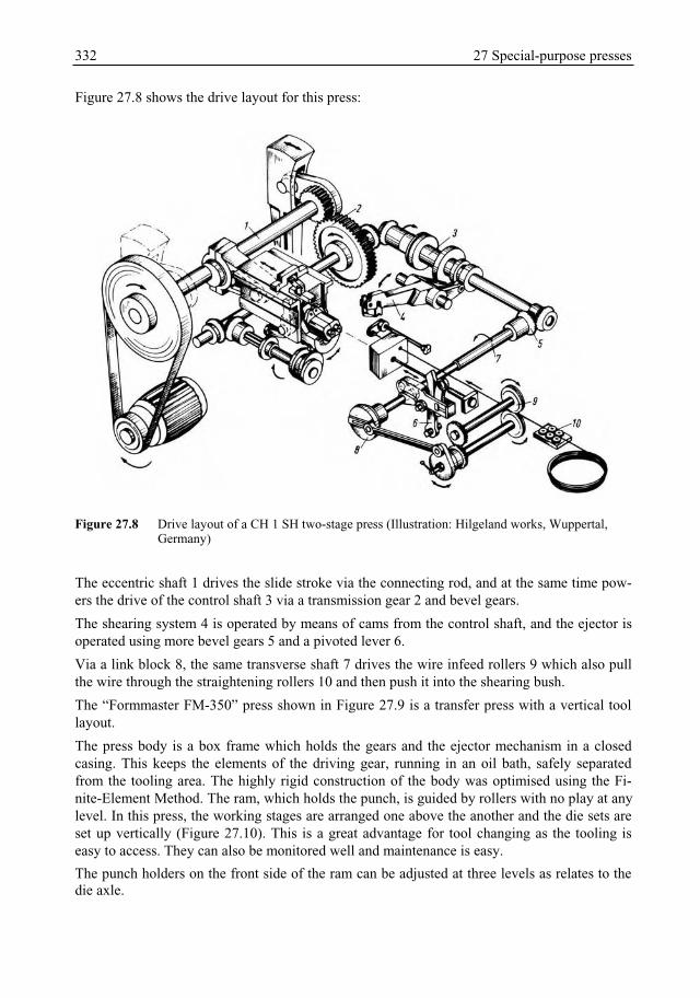
332 27 Special-purpose presses
Figure 27.8 shows the drive layout for this press:
Figure 27.8 Drive layout of a CH 1 SH two-stage press (Illustration: Hilgeland works, Wuppertal, Germany)
The eccentric shaft 1 drives the slide stroke via the connecting rod, and at the same time pow-ers the drive of the control shaft 3 via a transmission gear 2 and bevel gears. The shearing system 4 is operated by means of cams from the control shaft, and the ejector is operated using more bevel gears 5 and a pivoted lever 6. Via a link block 8, the same transverse shaft 7 drives the wire infeed rollers 9 which also pull the wire through the straightening rollers 10 and then push it into the shearing bush. The “Formmaster FM-350” press shown in Figure 27.9 is a transfer press with a vertical tool layout. The press body is a box frame which holds the gears and the ejector mechanism in a closed casing. This keeps the elements of the driving gear, running in an oil bath, safely separated from the tooling area. The highly rigid construction of the body was optimised using the Fi-nite-Element Method. The ram, which holds the punch, is guided by rollers with no play at any level. In this press, the working stages are arranged one above the another and the die sets are set up vertically (Figure 27.10). This is a great advantage for tool changing as the tooling is easy to access. They can also be monitored well and maintenance is easy. The punch holders on the front side of the ram can be adjusted at three levels as relates to the die axle.
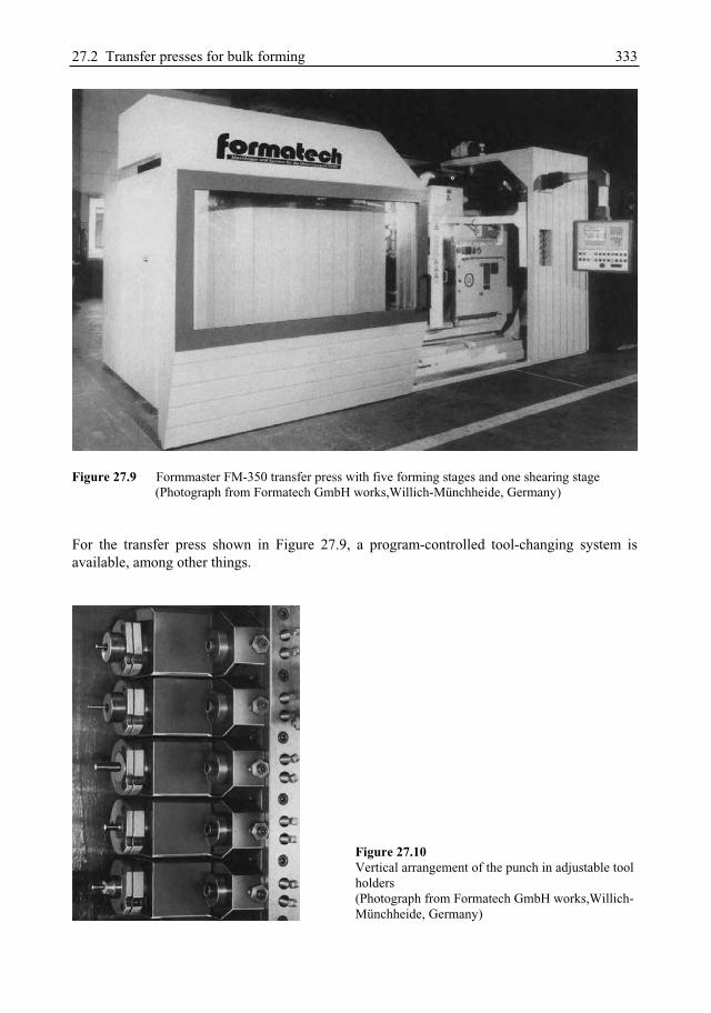
27.2 Transfer presses for bulk forming 333
Figure 27.9 Formmaster FM-350 transfer press with five forming stages and one shearing stage (Photograph from Formatech GmbH works,Willich-Münchheide, Germany)
For the transfer press shown in Figure 27.9, a program-controlled tool-changing system is available, among other things.
Figure 27.10 Vertical arrangement of the punch in adjustable tool holders(Photograph from Formatech GmbH works,Willich-Münchheide, Germany)

334 27 Special-purpose presses
The fact that the punch holder and punch can be precisely adjusted and the ram is guided with no play guarantees consistently small tolerances in the finished part and long tool lives. The manufacturing plants typically used in bulk forming are capital-intensive, and their cost-efficiency depends crucially upon the percentage of the total production time taken up by non-productive time and set-up time. Here, tool changing and set-up systems can make a vital con-tribution to shortening these non-productive times and lengthening the time the press is in action.
As manufacturing structures can differ greatly as concerns part size, lot size, processing and the manufacturing sequence, various systems for fast tool changing are available on the mar-ket: the operator can choose a combination suited to the operation.
With this tool-changing system all the tooling is adjusted and changed fully automatically when the press set-up is changed. This reduces changeover times drastically. The result is flexible manufacturing which means these presses can also be used economically for smaller lot sizes.
The die block, shearing block and punch blocks, which are mounted on a single die plate, are changed as one unit. The press is equipped with a special device to help carry out the change. The die block and the die plate are clamped in place with quick-action hydraulic devices which can easily be released.
The shearing blade, shearing bush, punch and die can still be changed separately, independ-ently of this fast tool-changing system.
The tooling being changed can be adjusted before it is mounted in the press. For this purpose the press has a tooling support area for adjusting tools, and a fixed holder for the die block and die plate, as well as appropriate adjustment devices.
The optimum settings for the X, Y and Z coordinates of a workpiece are determined once for every stage and then saved in the tooling databank. When the tooling is changed, these saved parameters can be called up at any time, even when the work is not being done on the press.
This makes tool changing faster, easier and safer. When the conditions of a process are the same, sound parts are produced right from the first strokes. With this system, a program ad-justs peripheral units: this is fully automatic. The ejector stroke and return stroke are adjusted with a motor. The feed system is set up to fit a wide range of diameters so that the grippers do not need changing when production is switched over.
A numerically controlled transfer system (Figure 27.11) is used to transport the workpieces within the press. The transfer system and grippers are operated by individually-controlled electric servo drives. The settings are adjusted using a menu it is no longer necessary to change camshafts or adjust cams. These settings are saved in a tooling databank and can be called up when needed within seconds.
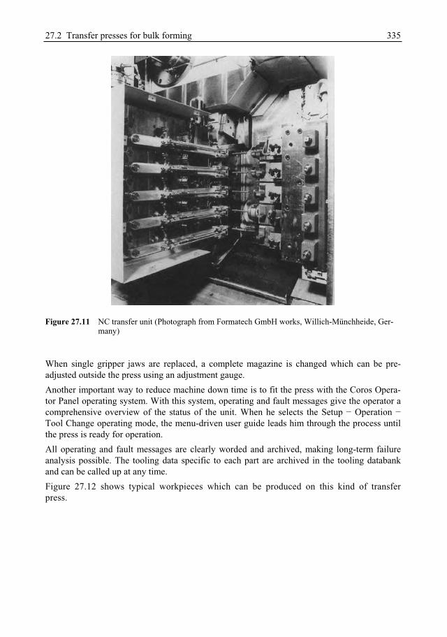
27.2 Transfer presses for bulk forming 335
Figure 27.11 NC transfer unit (Photograph from Formatech GmbH works, Willich-Münchheide, Ger-many)
When single gripper jaws are replaced, a complete magazine is changed which can be pre-adjusted outside the press using an adjustment gauge. Another important way to reduce machine down time is to fit the press with the Coros Opera-tor Panel operating system. With this system, operating and fault messages give the operator a comprehensive overview of the status of the unit. When he selects the Setup Operation Tool Change operating mode, the menu-driven user guide leads him through the process until the press is ready for operation. All operating and fault messages are clearly worded and archived, making long-term failure analysis possible. The tooling data specific to each part are archived in the tooling databank and can be called up at any time. Figure 27.12 shows typical workpieces which can be produced on this kind of transfer press.
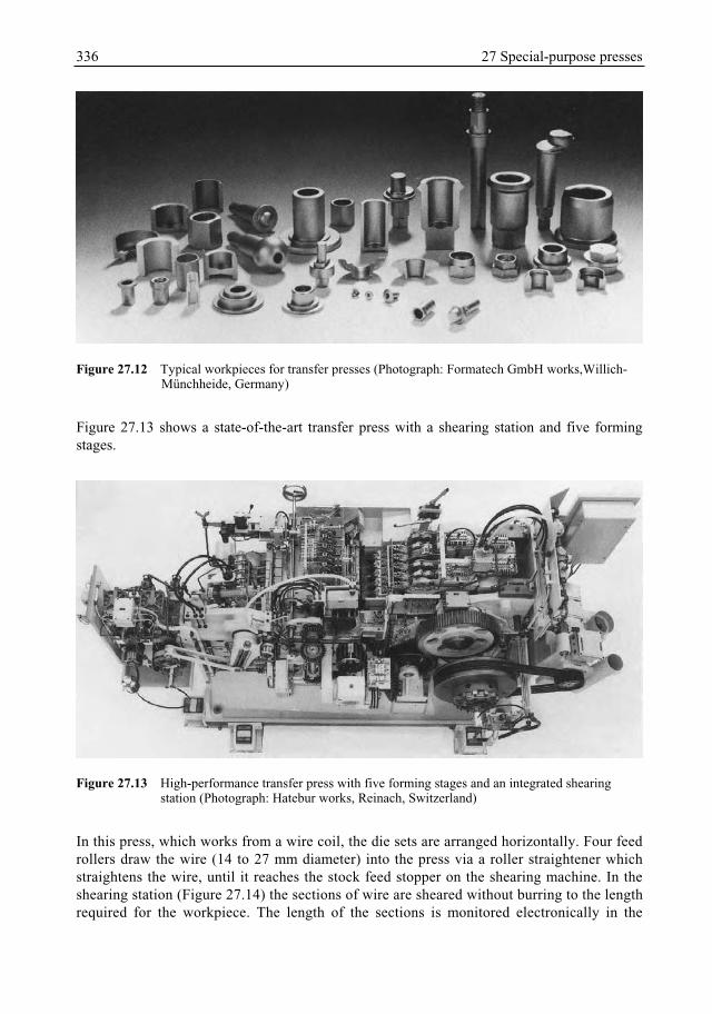
336 27 Special-purpose presses
Figure 27.12 Typical workpieces for transfer presses (Photograph: Formatech GmbH works,Willich-Münchheide, Germany)
Figure 27.13 shows a state-of-the-art transfer press with a shearing station and five forming stages.
Figure 27.13 High-performance transfer press with five forming stages and an integrated shearing station (Photograph: Hatebur works, Reinach, Switzerland)
In this press, which works from a wire coil, the die sets are arranged horizontally. Four feed rollers draw the wire (14 to 27 mm diameter) into the press via a roller straightener which straightens the wire, until it reaches the stock feed stopper on the shearing machine. In the shearing station (Figure 27.14) the sections of wire are sheared without burring to the length required for the workpiece. The length of the sections is monitored electronically in the
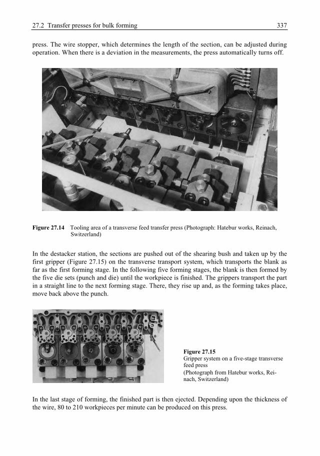
27.2 Transfer presses for bulk forming 337
press. The wire stopper, which determines the length of the section, can be adjusted during operation. When there is a deviation in the measurements, the press automatically turns off.
Figure 27.14 Tooling area of a transverse feed transfer press (Photograph: Hatebur works, Reinach, Switzerland)
In the destacker station, the sections are pushed out of the shearing bush and taken up by the first gripper (Figure 27.15) on the transverse transport system, which transports the blank as far as the first forming stage. In the following five forming stages, the blank is then formed by the five die sets (punch and die) until the workpiece is finished. The grippers transport the part in a straight line to the next forming stage. There, they rise up and, as the forming takes place, move back above the punch.
Figure 27.15 Gripper system on a five-stage transverse feed press (Photograph from Hatebur works, Rei-nach, Switzerland)
In the last stage of forming, the finished part is then ejected. Depending upon the thickness of the wire, 80 to 210 workpieces per minute can be produced on this press.
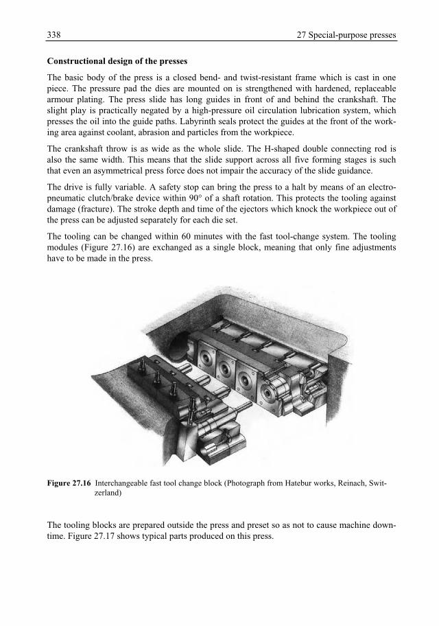
338 27 Special-purpose presses
Constructional design of the presses
The basic body of the press is a closed bend- and twist-resistant frame which is cast in one piece. The pressure pad the dies are mounted on is strengthened with hardened, replaceable armour plating. The press slide has long guides in front of and behind the crankshaft. The slight play is practically negated by a high-pressure oil circulation lubrication system, which presses the oil into the guide paths. Labyrinth seals protect the guides at the front of the work-ing area against coolant, abrasion and particles from the workpiece.
The crankshaft throw is as wide as the whole slide. The H-shaped double connecting rod is also the same width. This means that the slide support across all five forming stages is such that even an asymmetrical press force does not impair the accuracy of the slide guidance.
The drive is fully variable. A safety stop can bring the press to a halt by means of an electro-pneumatic clutch/brake device within 90° of a shaft rotation. This protects the tooling against damage (fracture). The stroke depth and time of the ejectors which knock the workpiece out of the press can be adjusted separately for each die set.
The tooling can be changed within 60 minutes with the fast tool-change system. The tooling modules (Figure 27.16) are exchanged as a single block, meaning that only fine adjustments have to be made in the press.
Figure 27.16 Interchangeable fast tool change block (Photograph from Hatebur works, Reinach, Swit-zerland)
The tooling blocks are prepared outside the press and preset so as not to cause machine down-time. Figure 27.17 shows typical parts produced on this press.
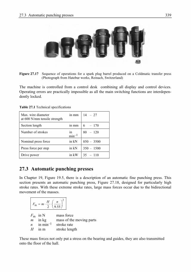
27.3 Automatic punching presses 339
Figure 27.17 Sequence of operations for a spark plug barrel produced on a Coldmatic transfer press (Photograph from Hatebur works, Reinach, Switzerland)
The machine is controlled from a control desk combining all display and control devices. Operating errors are practically impossible as all the main switching functions are interdepen-dently locked.
Table 27.1 Technical specifications
Max. wire diameter in mm at 600 N/mm tensile strength
14 – 27
Section length in mm 6 – 170
Number of strokes in min–1
80 – 120
Nominal press force in kN 850 – 3500
Press force per step in kN 350 – 1500
Drive power in kW 35 – 110
27.3 Automatic punching presses In Chapter 19, Figure 19.5, there is a description of an automatic fine punching press. This section presents an automatic punching press, Figure 27.18, designed for particularly high stroke rates. With these extreme stroke rates, large mass forces occur due to the bidirectional movement of the masses.
2
m 2 9.55H nF m
Fm in N mass force m in kg mass of the moving parts n in min–1 stroke rate H in m stroke length
These mass forces not only put a stress on the bearing and guides, they are also transmitted onto the floor of the hall.
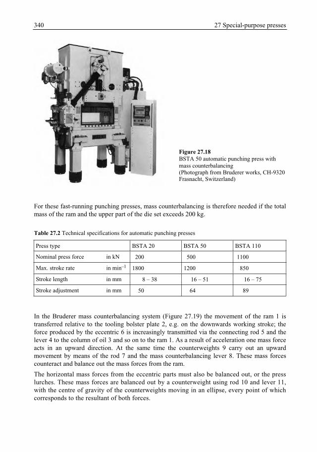
340 27 Special-purpose presses
Figure 27.18 BSTA 50 automatic punching press with mass counterbalancing (Photograph from Bruderer works, CH-9320 Frasnacht, Switzerland)
For these fast-running punching presses, mass counterbalancing is therefore needed if the total mass of the ram and the upper part of the die set exceeds 200 kg.
Table 27.2 Technical specifications for automatic punching presses
Press type BSTA 20 BSTA 50 BSTA 110
Nominal press force in kN 200 500 1100
Max. stroke rate in min–1 1800 1200 850
Stroke length in mm 8 – 38 16 – 51 16 – 75
Stroke adjustment in mm 50 64 89
In the Bruderer mass counterbalancing system (Figure 27.19) the movement of the ram 1 is transferred relative to the tooling bolster plate 2, e.g. on the downwards working stroke; the force produced by the eccentric 6 is increasingly transmitted via the connecting rod 5 and the lever 4 to the column of oil 3 and so on to the ram 1. As a result of acceleration one mass force acts in an upward direction. At the same time the counterweights 9 carry out an upward movement by means of the rod 7 and the mass counterbalancing lever 8. These mass forces counteract and balance out the mass forces from the ram. The horizontal mass forces from the eccentric parts must also be balanced out, or the press lurches. These mass forces are balanced out by a counterweight using rod 10 and lever 11, with the centre of gravity of the counterweights moving in an ellipse, every point of which corresponds to the resultant of both forces.
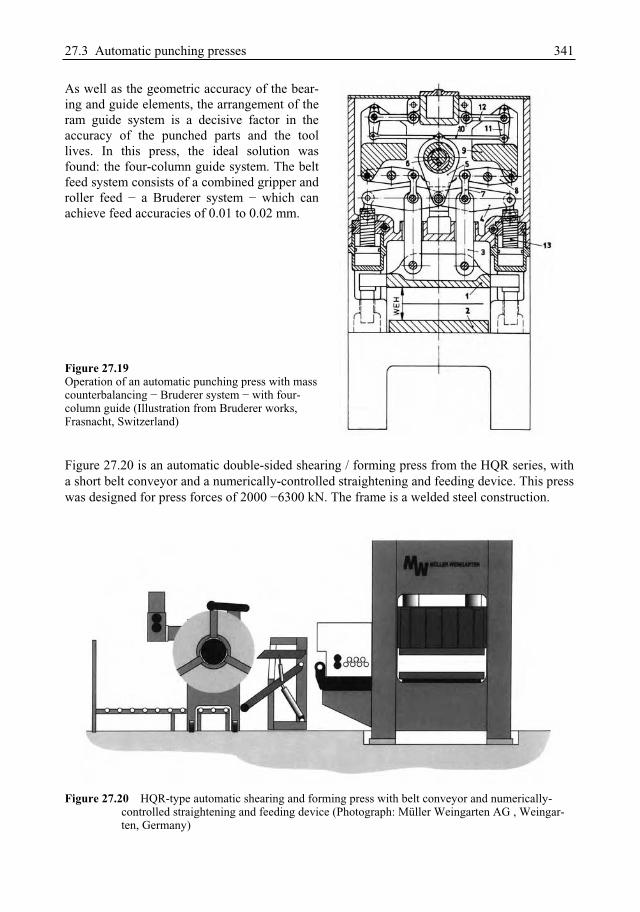
27.3 Automatic punching presses 341
As well as the geometric accuracy of the bear-ing and guide elements, the arrangement of the ram guide system is a decisive factor in the accuracy of the punched parts and the tool lives. In this press, the ideal solution was found: the four-column guide system. The belt feed system consists of a combined gripper and roller feed a Bruderer system which can achieve feed accuracies of 0.01 to 0.02 mm.
Figure 27.19 Operation of an automatic punching press with mass counterbalancing Bruderer system with four-column guide (Illustration from Bruderer works, Frasnacht, Switzerland)
Figure 27.20 is an automatic double-sided shearing / forming press from the HQR series, with a short belt conveyor and a numerically-controlled straightening and feeding device. This press was designed for press forces of 2000 6300 kN. The frame is a welded steel construction.
Figure 27.20 HQR-type automatic shearing and forming press with belt conveyor and numerically-controlled straightening and feeding device (Photograph: Müller Weingarten AG , Weingar-ten, Germany)
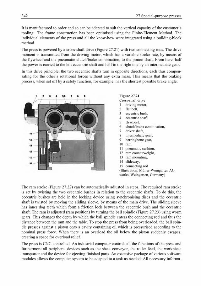
342 27 Special-purpose presses
It is manufactured to order and so can be adapted to suit the vertical capacity of the customer’s tooling The frame construction has been optimised using the Finite-Element Method. The individual elements of the press and all the know-how were integrated using a building-block method. The press is powered by a cross-shaft drive (Figure 27.21) with two connecting rods. The drive moment is transmitted from the driving motor, which has a variable stroke rate, by means of the flywheel and the pneumatic clutch/brake combination, to the pinion shaft. From here, half the power is carried to the left eccentric shaft and half to the right one by an intermediate gear. In this drive principle, the two eccentric shafts turn in opposite directions, each thus compen-sating for the other’s rotational forces without any extra mass. This means that the braking process, when set off by a safety function, for example, has the shortest possible brake angle.
Figure 27.21Cross-shaft drive 1 driving motor, 2 flat belt, 3 eccentric bush, 4 eccentric shaft, 5 flywheel, 6 clutch/brake combination, 7 driver shaft, 8 intermediate gear, 9 herringbone gear, 10 ram, 11 pneumatic cushion, 12 ram counterweight, 13 ram mounting, 14 slideway, 15 connecting rod (Illustration: Müller-Weingarten AG works, Weingarten, Germany)
The ram stroke (Figure 27.22) can be automatically adjusted in steps. The required ram stroke is set by twisting the two eccentric bushes in relation to the eccentric shafts. To do this, the eccentric bushes are held in the locking device using synchronising discs and the eccentric shaft is twisted by moving the sliding sleeve, by means of the main drive. The sliding sleeve has inner dog teeth which form a friction lock between the eccentric bush and the eccentric shaft. The ram is adjusted (ram position) by turning the ball spindle (Figure 27.23) using worm gears. This changes the depth by which the ball spindle enters the connecting rod and thus the distance between the ram and the table. To stop the press from being overloaded, the ball spin-dle presses against a piston onto a cavity containing oil which is pressurised according to the nominal press force. When there is an overload the oil below the piston suddenly escapes, creating a space for overload relief.The press is CNC controlled. An industrial computer controls all the functions of the press and furthermore all peripheral devices such as the sheet conveyor, the roller feed, the workpiece transporter and the device for ejecting finished parts. An extensive package of various software modules allows the computer system to be adapted to a task as needed. All necessary informa-
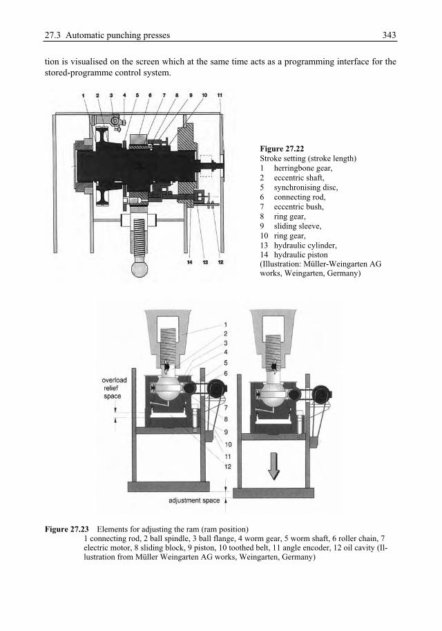
27.3 Automatic punching presses 343
tion is visualised on the screen which at the same time acts as a programming interface for the stored-programme control system.
Figure 27.22 Stroke setting (stroke length) 1 herringbone gear, 2 eccentric shaft, 5 synchronising disc, 6 connecting rod, 7 eccentric bush, 8 ring gear, 9 sliding sleeve, 10 ring gear, 13 hydraulic cylinder, 14 hydraulic piston (Illustration: Müller-Weingarten AG works, Weingarten, Germany)
Figure 27.23 Elements for adjusting the ram (ram position) 1 connecting rod, 2 ball spindle, 3 ball flange, 4 worm gear, 5 worm shaft, 6 roller chain, 7
electric motor, 8 sliding block, 9 piston, 10 toothed belt, 11 angle encoder, 12 oil cavity (Il-lustration from Müller Weingarten AG works, Weingarten, Germany)

344 27 Special-purpose presses
Table 27.3 Technical specifications for HQR automatic punching presses
Nominal press force kN 2000 – 6300 Stroke rate per min. 80 – 150 Ram stroke mm 200 – 250 Bolster plate mm
Length 1900 – 2800
Depth 1100 – 1400
27.4 Exercise on Chapter 27
1. What are the distinctive features of a transfer drawing press and what workpieces is it used for?
2. How do transfer presses for bulk forming differ and what are they used for? 3. What number of strokes per minute do automatic punching presses have? 4. Why do automatic punching presses require mass counterbalancing? 5. How is the stroke adjusted on an eccentric press? 6. Why are hydraulic extrusion presses used for long extruded workpieces? 7. What is the advantage of transfer presses? 8. What different types of transfer press construction are there? 9. Which workpieces are manufactured only on transfer presses? 10. Which elements of a transfer press transport the workpieces from die set to die set? 11. What is meant by a flexible manufacturing system?
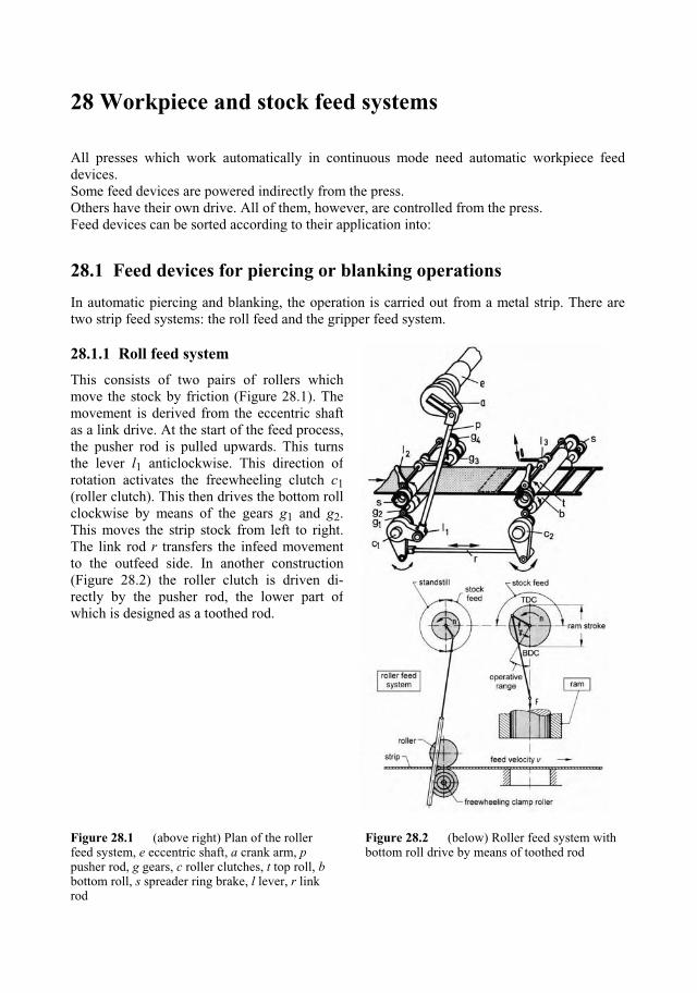
28 Workpiece and stock feed systems
All presses which work automatically in continuous mode need automatic workpiece feed devices. Some feed devices are powered indirectly from the press. Others have their own drive. All of them, however, are controlled from the press. Feed devices can be sorted according to their application into:
28.1 Feed devices for piercing or blanking operations In automatic piercing and blanking, the operation is carried out from a metal strip. There are two strip feed systems: the roll feed and the gripper feed system.
28.1.1 Roll feed system This consists of two pairs of rollers which move the stock by friction (Figure 28.1). The movement is derived from the eccentric shaft as a link drive. At the start of the feed process, the pusher rod is pulled upwards. This turns the lever l1 anticlockwise. This direction ofrotation activates the freewheeling clutch c1(roller clutch). This then drives the bottom roll clockwise by means of the gears g1 and g2.This moves the strip stock from left to right. The link rod r transfers the infeed movement to the outfeed side. In another construction (Figure 28.2) the roller clutch is driven di-rectly by the pusher rod, the lower part ofwhich is designed as a toothed rod.
Figure 28.1 (above right) Plan of the roller feed system, e eccentric shaft, a crank arm, ppusher rod, g gears, c roller clutches, t top roll, bbottom roll, s spreader ring brake, l lever, r link rod
Figure 28.2 (below) Roller feed system with bottom roll drive by means of toothed rod
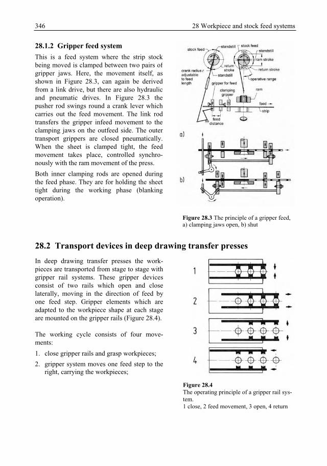
346 28 Workpiece and stock feed systems
28.1.2 Gripper feed system This is a feed system where the strip stock being moved is clamped between two pairs ofgripper jaws. Here, the movement itself, as shown in Figure 28.3, can again be derived from a link drive, but there are also hydraulic and pneumatic drives. In Figure 28.3 the pusher rod swings round a crank lever which carries out the feed movement. The link rod transfers the gripper infeed movement to the clamping jaws on the outfeed side. The outer transport grippers are closed pneumatically. When the sheet is clamped tight, the feed movement takes place, controlled synchro-nously with the ram movement of the press. Both inner clamping rods are opened during the feed phase. They are for holding the sheet tight during the working phase (blanking operation).
Figure 28.3 The principle of a gripper feed, a) clamping jaws open, b) shut
28.2 Transport devices in deep drawing transfer presses In deep drawing transfer presses the work-pieces are transported from stage to stage with gripper rail systems. These gripper devices consist of two rails which open and close laterally, moving in the direction of feed by one feed step. Gripper elements which are adapted to the workpiece shape at each stage are mounted on the gripper rails (Figure 28.4).
The working cycle consists of four move-ments: 1. close gripper rails and grasp workpieces; 2. gripper system moves one feed step to the
right, carrying the workpieces;
Figure 28.4 The operating principle of a gripper rail sys-tem. 1 close, 2 feed movement, 3 open, 4 return
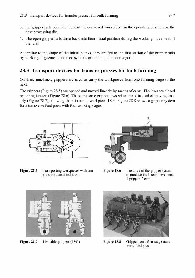
28.3 Transport devices for transfer presses for bulk forming 347
3. the gripper rails open and deposit the conveyed workpieces in the operating position on the next processing die.
4. The open gripper rails drive back into their initial position during the working movement of the ram.
According to the shape of the initial blanks, they are fed to the first station of the gripper rails by stacking magazines, disc feed systems or other suitable conveyors.
28.3 Transport devices for transfer presses for bulk forming On these machines, grippers are used to carry the workpieces from one forming stage to the next. The grippers (Figure 28.5) are opened and moved linearly by means of cams. The jaws are closed by spring tension (Figure 28.6). There are some gripper jaws which pivot instead of moving line-arly (Figure 28.7), allowing them to turn a workpiece 180°. Figure 28.8 shows a gripper system for a transverse feed press with four working stages.
Figure 28.5 Transporting workpieces with sim-ple spring-actuated jaws
Figure 28.6 The drive of the gripper system to produce the linear movement.1 gripper, 2 cam
Figure 28.7 Pivotable grippers (180°) Figure 28.8 Grippers on a four-stage trans-verse feed press
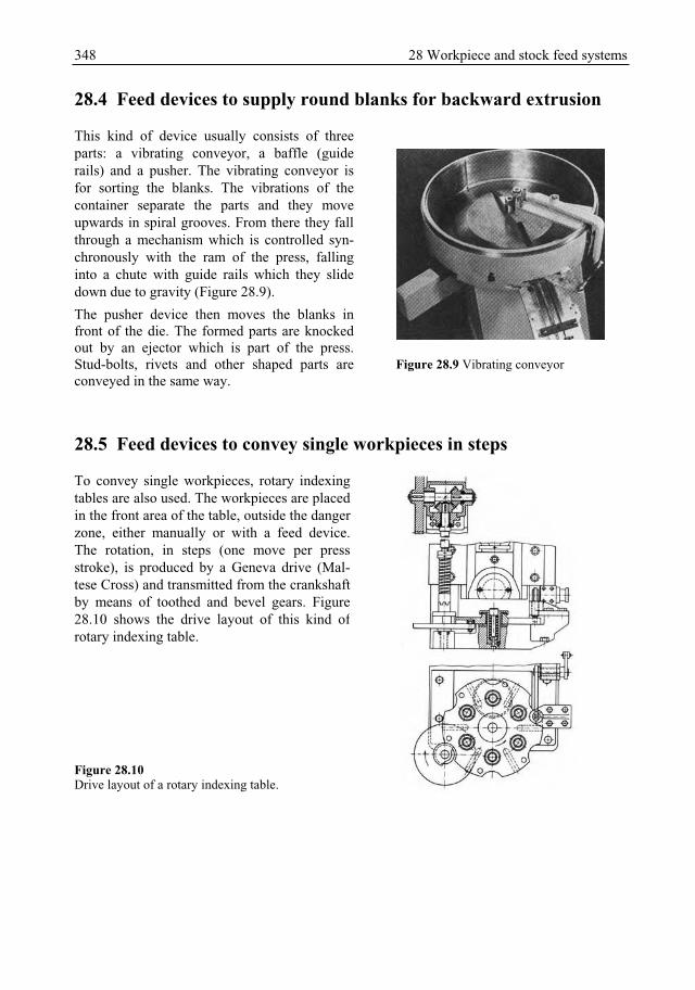
348 28 Workpiece and stock feed systems
28.4 Feed devices to supply round blanks for backward extrusion
This kind of device usually consists of three parts: a vibrating conveyor, a baffle (guide rails) and a pusher. The vibrating conveyor is for sorting the blanks. The vibrations of the container separate the parts and they move upwards in spiral grooves. From there they fall through a mechanism which is controlled syn-chronously with the ram of the press, falling into a chute with guide rails which they slide down due to gravity (Figure 28.9). The pusher device then moves the blanks in front of the die. The formed parts are knocked out by an ejector which is part of the press. Stud-bolts, rivets and other shaped parts are conveyed in the same way.
Figure 28.9 Vibrating conveyor
28.5 Feed devices to convey single workpieces in steps
To convey single workpieces, rotary indexing tables are also used. The workpieces are placed in the front area of the table, outside the danger zone, either manually or with a feed device. The rotation, in steps (one move per press stroke), is produced by a Geneva drive (Mal-tese Cross) and transmitted from the crankshaft by means of toothed and bevel gears. Figure 28.10 shows the drive layout of this kind ofrotary indexing table.
Figure 28.10 Drive layout of a rotary indexing table.

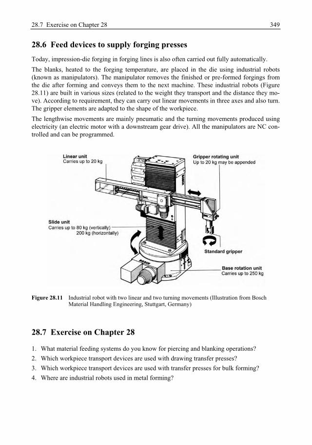
28.7 Exercise on Chapter 28 349
28.6 Feed devices to supply forging presses Today, impression-die forging in forging lines is also often carried out fully automatically. The blanks, heated to the forging temperature, are placed in the die using industrial robots (known as manipulators). The manipulator removes the finished or pre-formed forgings from the die after forming and conveys them to the next machine. These industrial robots (Figure 28.11) are built in various sizes (related to the weight they transport and the distance they mo-ve). According to requirement, they can carry out linear movements in three axes and also turn. The gripper elements are adapted to the shape of the workpiece. The lengthwise movements are mainly pneumatic and the turning movements produced using electricity (an electric motor with a downstream gear drive). All the manipulators are NC con-trolled and can be programmed.
Figure 28.11 Industrial robot with two linear and two turning movements (Illustration from Bosch Material Handling Engineering, Stuttgart, Germany)
28.7 Exercise on Chapter 28
1. What material feeding systems do you know for piercing and blanking operations? 2. Which workpiece transport devices are used with drawing transfer presses? 3. Which workpiece transport devices are used with transfer presses for bulk forming? 4. Where are industrial robots used in metal forming?
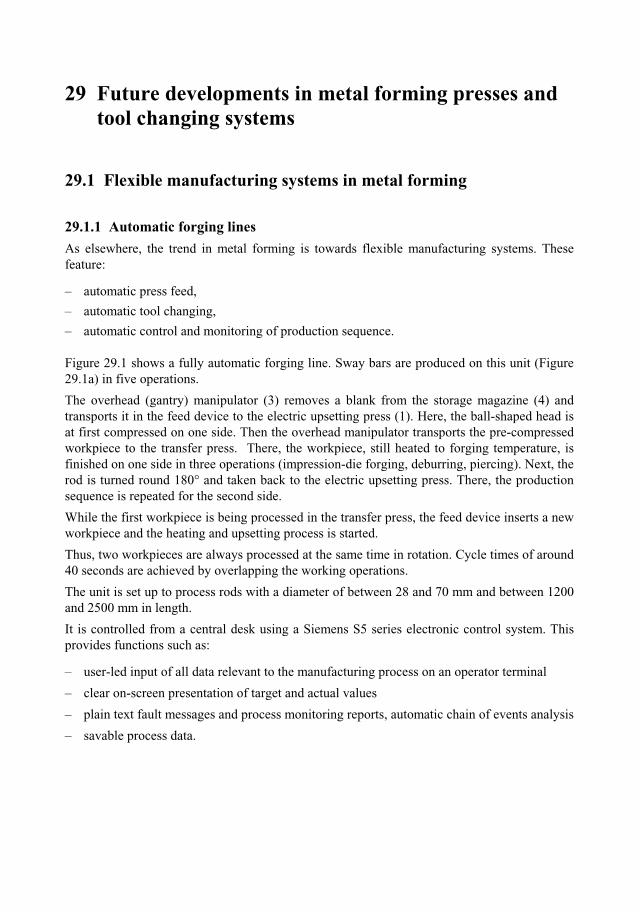
29 Future developments in metal forming presses and tool changing systems
29.1 Flexible manufacturing systems in metal forming
29.1.1 Automatic forging lines As elsewhere, the trend in metal forming is towards flexible manufacturing systems. These feature:
– automatic press feed, – automatic tool changing, – automatic control and monitoring of production sequence.
Figure 29.1 shows a fully automatic forging line. Sway bars are produced on this unit (Figure 29.1a) in five operations. The overhead (gantry) manipulator (3) removes a blank from the storage magazine (4) and transports it in the feed device to the electric upsetting press (1). Here, the ball-shaped head is at first compressed on one side. Then the overhead manipulator transports the pre-compressed workpiece to the transfer press. There, the workpiece, still heated to forging temperature, is finished on one side in three operations (impression-die forging, deburring, piercing). Next, the rod is turned round 180° and taken back to the electric upsetting press. There, the production sequence is repeated for the second side. While the first workpiece is being processed in the transfer press, the feed device inserts a new workpiece and the heating and upsetting process is started. Thus, two workpieces are always processed at the same time in rotation. Cycle times of around 40 seconds are achieved by overlapping the working operations. The unit is set up to process rods with a diameter of between 28 and 70 mm and between 1200 and 2500 mm in length. It is controlled from a central desk using a Siemens S5 series electronic control system. This provides functions such as:
– user-led input of all data relevant to the manufacturing process on an operator terminal – clear on-screen presentation of target and actual values – plain text fault messages and process monitoring reports, automatic chain of events analysis – savable process data.
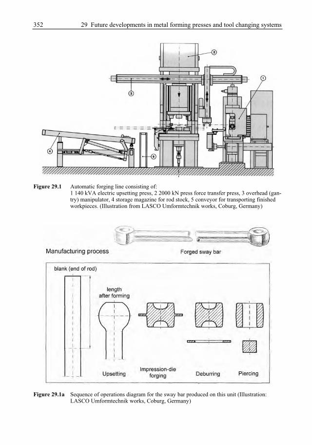
352 29 Future developments in metal forming presses and tool changing systems
Figure 29.1 Automatic forging line consisting of: 1 140 kVA electric upsetting press, 2 2000 kN press force transfer press, 3 overhead (gan-try) manipulator, 4 storage magazine for rod stock, 5 conveyor for transporting finished workpieces. (Illustration from LASCO Umformtechnik works, Coburg, Germany)
Figure 29.1a Sequence of operations diagram for the sway bar produced on this unit (Illustration: LASCO Umformtechnik works, Coburg, Germany)
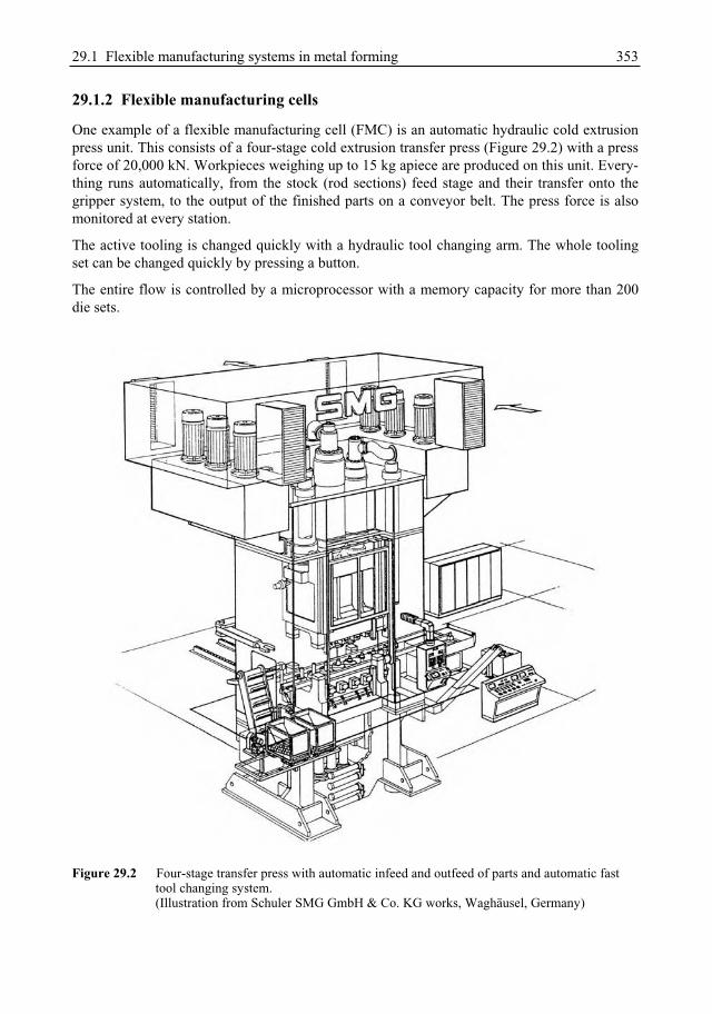
29.1 Flexible manufacturing systems in metal forming 353
29.1.2 Flexible manufacturing cells
One example of a flexible manufacturing cell (FMC) is an automatic hydraulic cold extrusion press unit. This consists of a four-stage cold extrusion transfer press (Figure 29.2) with a press force of 20,000 kN. Workpieces weighing up to 15 kg apiece are produced on this unit. Every-thing runs automatically, from the stock (rod sections) feed stage and their transfer onto the gripper system, to the output of the finished parts on a conveyor belt. The press force is also monitored at every station.
The active tooling is changed quickly with a hydraulic tool changing arm. The whole tooling set can be changed quickly by pressing a button.
The entire flow is controlled by a microprocessor with a memory capacity for more than 200 die sets.
Figure 29.2 Four-stage transfer press with automatic infeed and outfeed of parts and automatic fast tool changing system. (Illustration from Schuler SMG GmbH & Co. KG works, Waghäusel, Germany)
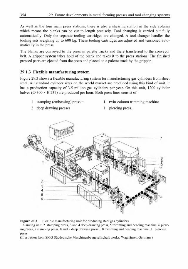
354 29 Future developments in metal forming presses and tool changing systems
As well as the four main press stations, there is also a shearing station in the side column which means the blanks can be cut to length precisely. Tool changing is carried out fully automatically. Only the separate tooling cartridges are changed. A tool changer handles the tooling sets weighing up to 600 kg. These tooling cartridges are adjusted and tensioned auto-matically in the press. The blanks are conveyed to the press in palette trucks and there transferred to the conveyor belt. A gripper system takes hold of the blank and takes it to the press stations. The finished pressed parts are ejected from the press and placed on a palette truck by the gripper.
29.1.3 Flexible manufacturing system Figure 29.3 shows a flexible manufacturing system for manufacturing gas cylinders from sheet steel. All standard cylinder sizes on the world market are produced using this kind of unit. It has a production capacity of 3.5 million gas cylinders per year. On this unit, 1200 cylinder halves ( 300 × H 235) are produced per hour. Both press lines consist of:
1 stamping (embossing) press 1 twin-column trimming machine 2 deep drawing presses 1 piercing press.
Figure 29.3 Flexible manufacturing unit for producing steel gas cylinders. 1 blanking unit, 2 stamping press, 3 and 4 deep drawing press, 5 trimming and beading machine, 6 pierc-ing press, 7 stamping press, 8 and 9 deep drawing press, 10 trimming and beading machine, 11 piercing press (Illustration from SMG Süddeutsche Maschinenbaugesellschaft works, Waghäusel, Germany)
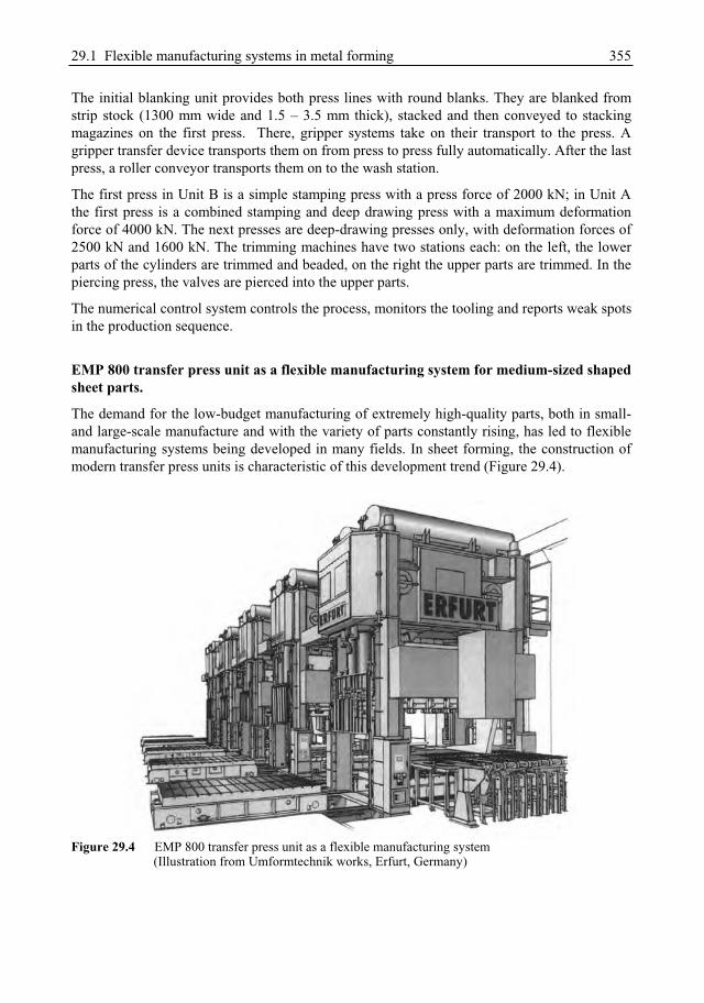
29.1 Flexible manufacturing systems in metal forming 355
The initial blanking unit provides both press lines with round blanks. They are blanked from strip stock (1300 mm wide and 1.5 – 3.5 mm thick), stacked and then conveyed to stacking magazines on the first press. There, gripper systems take on their transport to the press. A gripper transfer device transports them on from press to press fully automatically. After the last press, a roller conveyor transports them on to the wash station.
The first press in Unit B is a simple stamping press with a press force of 2000 kN; in Unit A the first press is a combined stamping and deep drawing press with a maximum deformation force of 4000 kN. The next presses are deep-drawing presses only, with deformation forces of 2500 kN and 1600 kN. The trimming machines have two stations each: on the left, the lower parts of the cylinders are trimmed and beaded, on the right the upper parts are trimmed. In the piercing press, the valves are pierced into the upper parts.
The numerical control system controls the process, monitors the tooling and reports weak spots in the production sequence.
EMP 800 transfer press unit as a flexible manufacturing system for medium-sized shaped sheet parts.
The demand for the low-budget manufacturing of extremely high-quality parts, both in small- and large-scale manufacture and with the variety of parts constantly rising, has led to flexible manufacturing systems being developed in many fields. In sheet forming, the construction of modern transfer press units is characteristic of this development trend (Figure 29.4).
Figure 29.4 EMP 800 transfer press unit as a flexible manufacturing system (Illustration from Umformtechnik works, Erfurt, Germany)
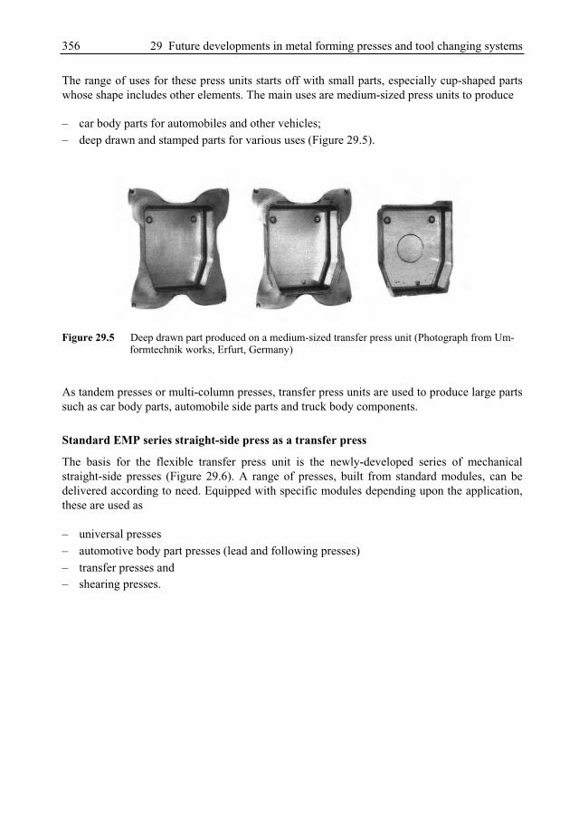
356 29 Future developments in metal forming presses and tool changing systems
The range of uses for these press units starts off with small parts, especially cup-shaped parts whose shape includes other elements. The main uses are medium-sized press units to produce
– car body parts for automobiles and other vehicles; – deep drawn and stamped parts for various uses (Figure 29.5).
Figure 29.5 Deep drawn part produced on a medium-sized transfer press unit (Photograph from Um-formtechnik works, Erfurt, Germany)
As tandem presses or multi-column presses, transfer press units are used to produce large parts such as car body parts, automobile side parts and truck body components.
Standard EMP series straight-side press as a transfer press
The basis for the flexible transfer press unit is the newly-developed series of mechanical straight-side presses (Figure 29.6). A range of presses, built from standard modules, can be delivered according to need. Equipped with specific modules depending upon the application, these are used as
– universal presses – automotive body part presses (lead and following presses) – transfer presses and – shearing presses.
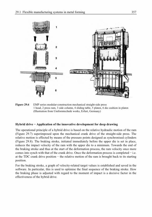
29.1 Flexible manufacturing systems in metal forming 357
Figure 29.6 EMP series modular-construction mechanical straight-side press 1 head, 2 press ram, 3 side column, 4 sliding table, 5 platen, 6 die cushion in platen(Illustration from Umformtechnik works, Erfurt, Germany)
Hybrid drive Application of the innovative development for deep drawing
The operational principle of a hybrid drive is based on the relative hydraulic motion of the ram (Figure 29.7) superimposed upon the mechanical crank drive of the straight-side press. The relative motion is effected by means of the pressure points designed as synchronised cylinders (Figure 29.8). The braking stroke, initiated immediately before the upper die is set in place, reduces the impact velocity of the ram with the upper die to a minimum. Towards the end of the braking stroke and thus at the start of the deformation process, the ram velocity once more comes into synch with that of the crank drive. Once the deformation process is completed i.e. at the TDC crank drive position the relative motion of the ram is brought back to its starting position. For the braking stroke, a graph of velocity-related target values is established and saved in the software. In particular, this is used to optimise the final sequence of the braking stroke. How the braking phase is adjusted with regard to the moment of impact is a decisive factor in the effectiveness of the hybrid drive.
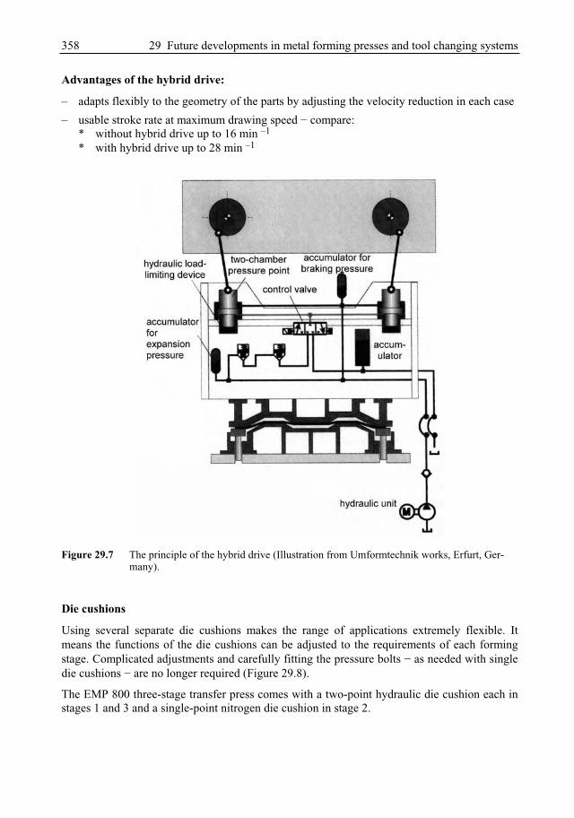
358 29 Future developments in metal forming presses and tool changing systems
Advantages of the hybrid drive:
– adapts flexibly to the geometry of the parts by adjusting the velocity reduction in each case – usable stroke rate at maximum drawing speed compare:
* without hybrid drive up to 16 min –1
* with hybrid drive up to 28 min –1
Figure 29.7 The principle of the hybrid drive (Illustration from Umformtechnik works, Erfurt, Ger-many).
Die cushions
Using several separate die cushions makes the range of applications extremely flexible. It means the functions of the die cushions can be adjusted to the requirements of each forming stage. Complicated adjustments and carefully fitting the pressure bolts as needed with single die cushions are no longer required (Figure 29.8).
The EMP 800 three-stage transfer press comes with a two-point hydraulic die cushion each in stages 1 and 3 and a single-point nitrogen die cushion in stage 2.
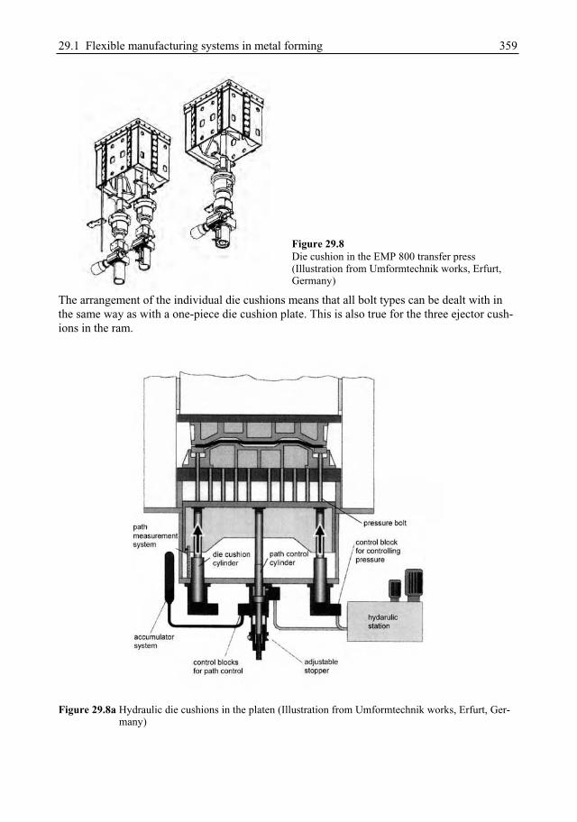
29.1 Flexible manufacturing systems in metal forming 359
Figure 29.8 Die cushion in the EMP 800 transfer press (Illustration from Umformtechnik works, Erfurt, Germany)
The arrangement of the individual die cushions means that all bolt types can be dealt with in the same way as with a one-piece die cushion plate. This is also true for the three ejector cush-ions in the ram.
Figure 29.8a Hydraulic die cushions in the platen (Illustration from Umformtechnik works, Erfurt, Ger-many)
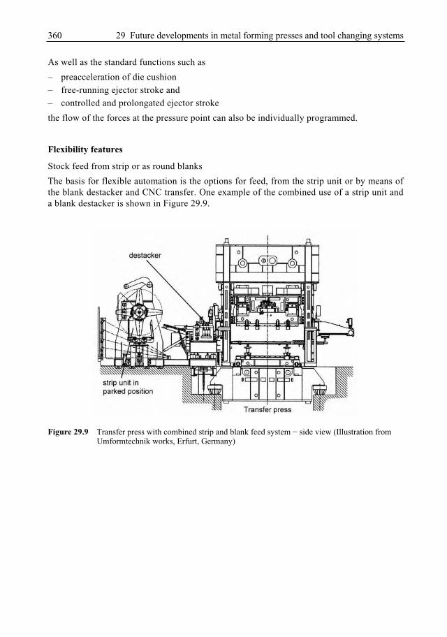
360 29 Future developments in metal forming presses and tool changing systems
As well as the standard functions such as – preacceleration of die cushion – free-running ejector stroke and – controlled and prolongated ejector stroke the flow of the forces at the pressure point can also be individually programmed.
Flexibility features
Stock feed from strip or as round blanks The basis for flexible automation is the options for feed, from the strip unit or by means of the blank destacker and CNC transfer. One example of the combined use of a strip unit and a blank destacker is shown in Figure 29.9.
Figure 29.9 Transfer press with combined strip and blank feed system side view (Illustration from Umformtechnik works, Erfurt, Germany)
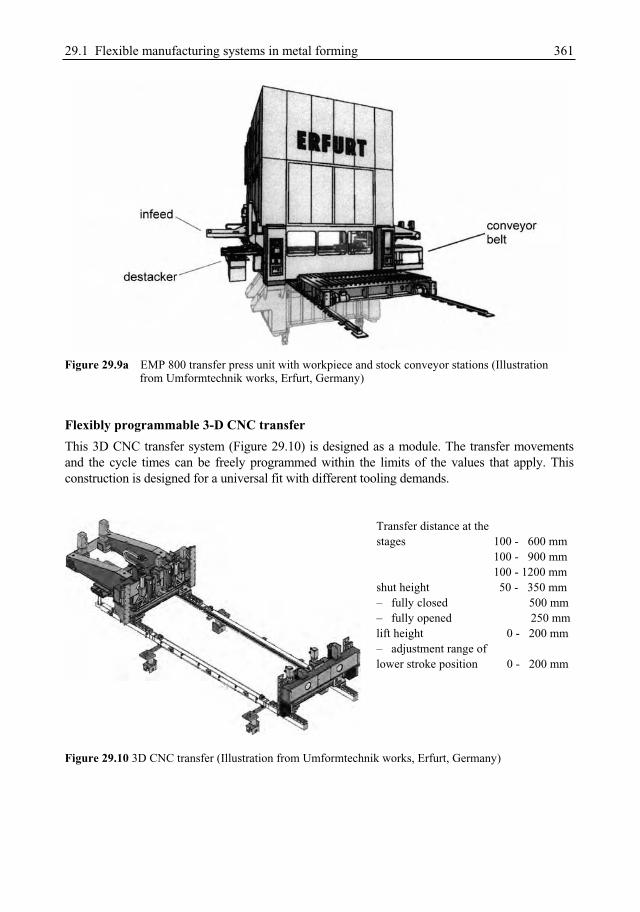
29.1 Flexible manufacturing systems in metal forming 361
Figure 29.9a EMP 800 transfer press unit with workpiece and stock conveyor stations (Illustration from Umformtechnik works, Erfurt, Germany)
Flexibly programmable 3-D CNC transfer This 3D CNC transfer system (Figure 29.10) is designed as a module. The transfer movements and the cycle times can be freely programmed within the limits of the values that apply. This construction is designed for a universal fit with different tooling demands.
Transfer distance at the stages 100 - 600 mm 100 - 900 mm 100 - 1200 mm shut height 50 - 350 mm– fully closed 500 mm– fully opened 250 mm lift height 0 - 200 mm– adjustment range of lower stroke position 0 - 200 mm
Figure 29.10 3D CNC transfer (Illustration from Umformtechnik works, Erfurt, Germany)

362 29 Future developments in metal forming presses and tool changing systems
Modular control system in an open, extendable structureAll necessary press control functions are fitted into a basic module according to the schematic design of the press control system. To add the many functions which make the transfer press unit fully automatic, and for a user-friendly display, each add-on module can be integrated as needed.
The most-used PLCs are: – SIMATIC S7 for Europe and – Allen Bradley PLC5 for the United States
Automatic tool changing reduces non-productive times
The press and transfer system adjustment data required for each die set can be saved in the press control system under a code number of the user’s choice. When the code number is en-tered the separate steps of the automatic tool changing process are activated by the sequence control system.
The destacker and strip handling unit also come with automatic devices for fast blank or coil changes.
Integrating the controls of the destacker and the strip unit in the press control system reduces the changeover time for the whole press unit to a minimum.
29.2 Automatic tool change systems One way to shorten tool changing times is to use cartridge-style tool holders (Figure 29.11). These cartridges are fixed in the working area of the press using quick-action hydraulic de-vices. These devices are released from the control desk, the cartridge is pulled onto a change-over table or changeover truck and replaced with a ready-to-install cartridge preheated to the operating temperature.
The sequence of events for tool changing is as follows:
1. Tooling cartridges are locked. The ram is moved down. 2. The lock is released and the ram is moved up. 3. The tool changing truck drives up to the press. The cartridge pack is lifted and coupled on
to the changing truck. 4. The cartridge pack is pulled onto the changing truck and is ready to be taken away.
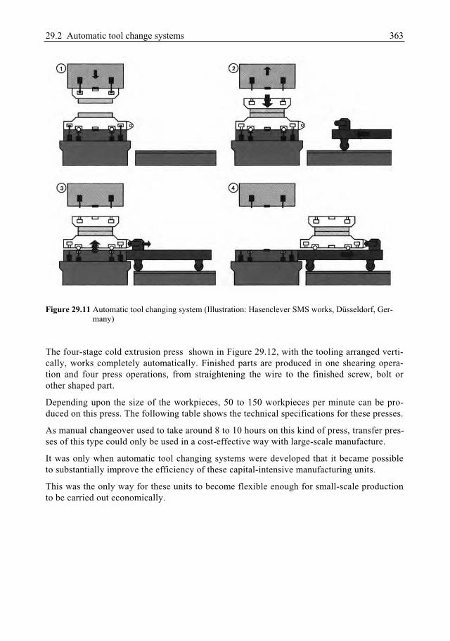
29.2 Automatic tool change systems 363
Figure 29.11 Automatic tool changing system (Illustration: Hasenclever SMS works, Düsseldorf, Ger-many)
The four-stage cold extrusion press shown in Figure 29.12, with the tooling arranged verti-cally, works completely automatically. Finished parts are produced in one shearing opera-tion and four press operations, from straightening the wire to the finished screw, bolt or other shaped part.
Depending upon the size of the workpieces, 50 to 150 workpieces per minute can be pro-duced on this press. The following table shows the technical specifications for these presses.
As manual changeover used to take around 8 to 10 hours on this kind of press, transfer pres-ses of this type could only be used in a cost-effective way with large-scale manufacture.
It was only when automatic tool changing systems were developed that it became possible to substantially improve the efficiency of these capital-intensive manufacturing units.
This was the only way for these units to become flexible enough for small-scale production to be carried out economically.
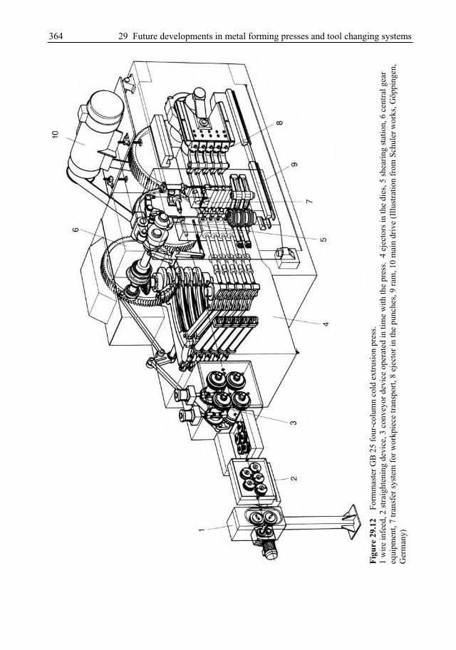
364 29 Future developments in metal forming presses and tool changing systems
Figu
re 2
9.12
Fo
rmm
aste
r GB
25
four
-col
umn
cold
ext
rusi
on p
ress
. 1
wire
infe
ed, 2
stra
ight
enin
g de
vice
, 3 c
onve
yor d
evic
e op
erat
ed in
tim
e w
ith th
e pr
ess.
4 e
ject
ors i
n th
e di
es, 5
shea
ring
s tatio
n, 6
cen
tral g
ear
equi
pmen
t, 7
trans
fer s
yste
m fo
r wor
kpie
ce tr
ansp
ort,
8 ej
ecto
r in
the
punc
hes,
9 ra
m, 1
0 m
ain
driv
e (I
llust
ratio
n fr
om S
chul
er w
orks
, Göp
ping
en,
Ger
man
y)
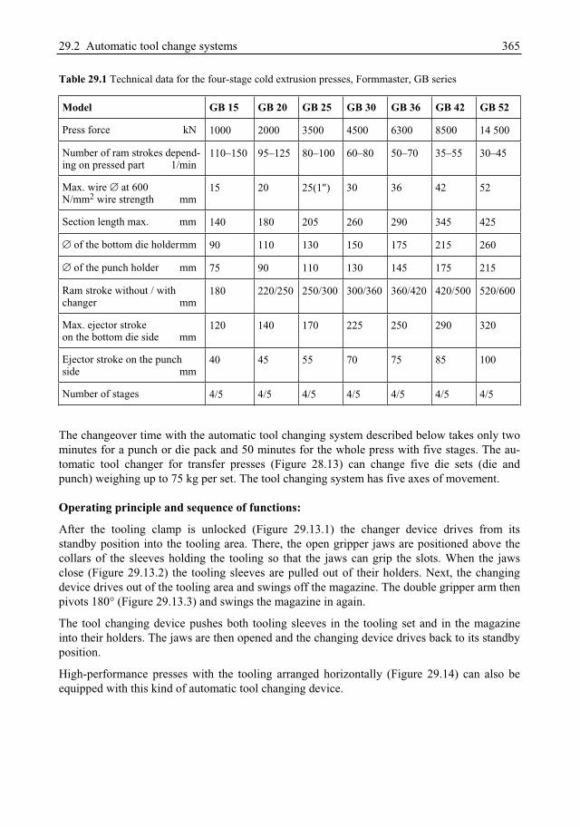
29.2 Automatic tool change systems 365
Table 29.1 Technical data for the four-stage cold extrusion presses, Formmaster, GB series
Model GB 15 GB 20 GB 25 GB 30 GB 36 GB 42 GB 52
Press force kN 1000 2000 3500 4500 6300 8500 14 500
Number of ram strokes depend-ing on pressed part 1/min
110–150 95–125 80–100 60–80 50–70 35–55 30–45
Max. wire at 600 N/mm2 wire strength mm
15 20 25(1") 30 36 42 52
Section length max. mm 140 180 205 260 290 345 425
of the bottom die holder mm 90 110 130 150 175 215 260
of the punch holder mm 75 90 110 130 145 175 215
Ram stroke without / with changer mm
180 220/250 250/300 300/360 360/420 420/500 520/600
Max. ejector stroke on the bottom die side mm
120 140 170 225 250 290 320
Ejector stroke on the punch side mm
40 45 55 70 75 85 100
Number of stages 4/5 4/5 4/5 4/5 4/5 4/5 4/5
The changeover time with the automatic tool changing system described below takes only two minutes for a punch or die pack and 50 minutes for the whole press with five stages. The au-tomatic tool changer for transfer presses (Figure 28.13) can change five die sets (die and punch) weighing up to 75 kg per set. The tool changing system has five axes of movement.
Operating principle and sequence of functions:
After the tooling clamp is unlocked (Figure 29.13.1) the changer device drives from its standby position into the tooling area. There, the open gripper jaws are positioned above the collars of the sleeves holding the tooling so that the jaws can grip the slots. When the jaws close (Figure 29.13.2) the tooling sleeves are pulled out of their holders. Next, the changing device drives out of the tooling area and swings off the magazine. The double gripper arm then pivots 180° (Figure 29.13.3) and swings the magazine in again.
The tool changing device pushes both tooling sleeves in the tooling set and in the magazine into their holders. The jaws are then opened and the changing device drives back to its standby position.
High-performance presses with the tooling arranged horizontally (Figure 29.14) can also be equipped with this kind of automatic tool changing device.
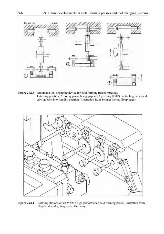
366 29 Future developments in metal forming presses and tool changing systems
Figure 29.13 Automatic tool changing device for cold forming transfer presses. 1 starting position, 2 tooling packs being gripped, 3 pivoting (180°) the tooling packs and driving back into standby position (Illustration from Schuler works, Göppingen)
Figure 29.14 Forming stations on an M2/M3 high-performance cold forming press (Illustration from Hilgeland works, Wuppertal, Germany)

Part III: Technical tables

368 Technical tables
Tab
le 1
kf 1
= f
(p)
in N
/mm
2 – so
ft an
neal
ed–
cold
form
ing
–
k f1 =
f(
p)M
ater
ial
f k0
0.1
0.2
0.4
0.6
0.8
1.0
1.2
1.4
1.6
1.8
2.0
p
QSt
32-
3(M
a 8)
25
042
049
658
664
669
273
076
379
281
8–
–C
k 10
26
045
052
360
766
370
674
077
079
681
9–
–C
q l5
/Ck
l5
280
520
583
654
700
733
760
783
803
821
––
Cq
22/C
k 22
32
053
059
165
870
273
476
078
280
181
8–
–C
q 35
/Ck
35
340
630
713
807
867
913
950
982
1008
1033
––
Cq
45/C
k 45
39
068
076
485
891
896
310
0010
3110
5810
82–
–C
f 53
430
770
867
975
1049
1098
1140
1176
––
––
15 C
rNi 6
42
070
076
784
188
892
295
097
399
310
11–
–16
MnC
r 5
380
630
702
780
832
869
900
926
948
968
34 C
rMo
4 41
073
080
889
394
799
810
2010
4810
7110
9242
CrM
o 4
420
780
865
959
1019
1064
1100
1130
1156
1180
CuZ
n 37
(Ms 6
3)
280
325
438
592
706
799
880
952
1018
1078
1134
1188
CuZ
n 30
(Ms 7
0)
250
280
395
558
682
788
880
964
1040
1112
1179
1242
Ti 9
9.8
600
700
862
1062
1200
1309
1400
1479
1549
1612
Al 9
9.8
6090
105
122
134
143
150
156
162
166
171
175
AlM
gSi 1
13
016
518
921
723
524
926
027
027
828
529
229
8
Con
tinue
d A
L 2.
42.
62.
83.
03.
23.
43.
63.
84.
04.
55.
0p
Al 9
9.8
60
182
185
188
191
194
196
200
202
204
210
214
Al M
gSi 1
13
030
931
431
832
332
733
133
533
834
2–
–
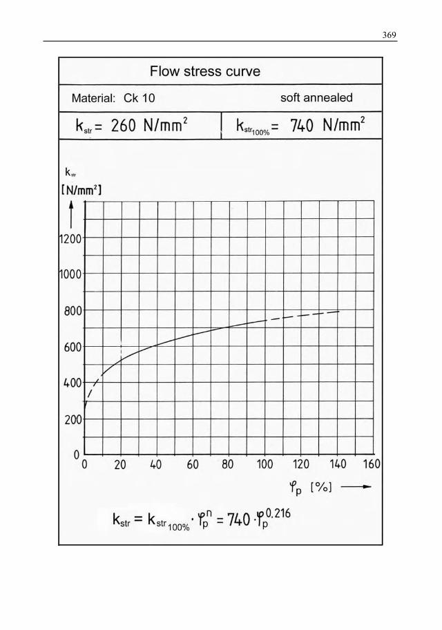
369
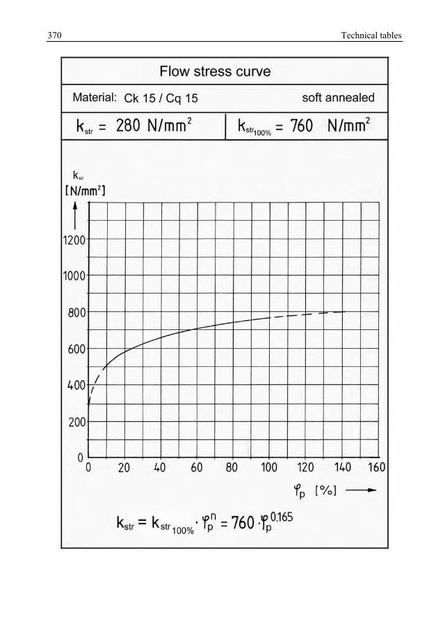
370 Technical tables
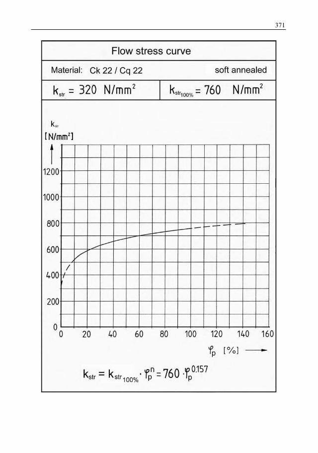
371
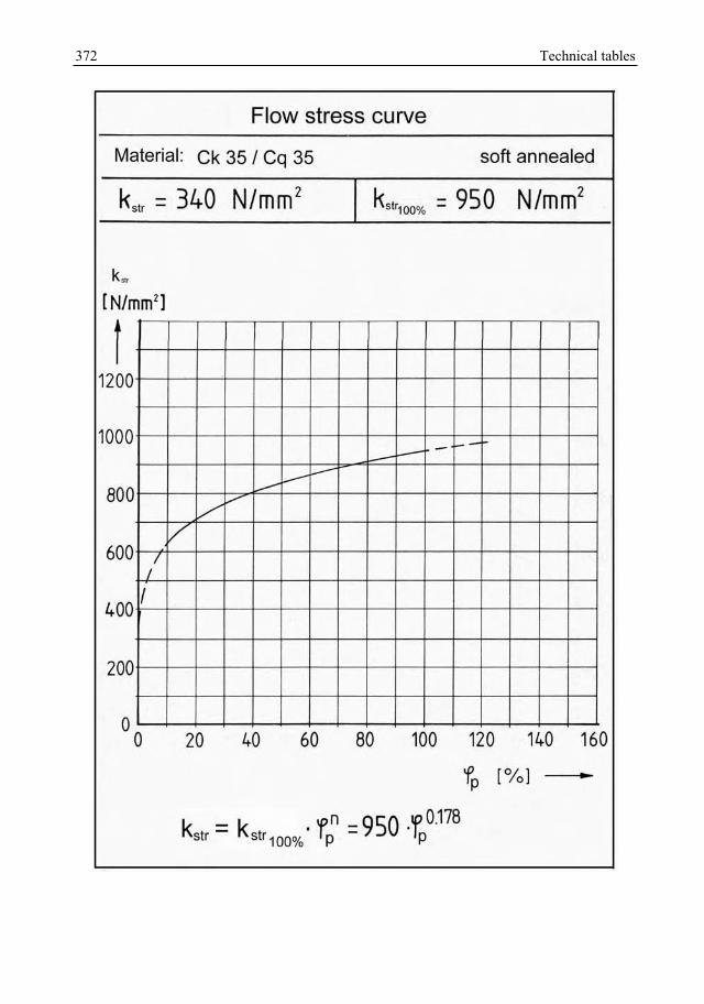
372 Technical tables
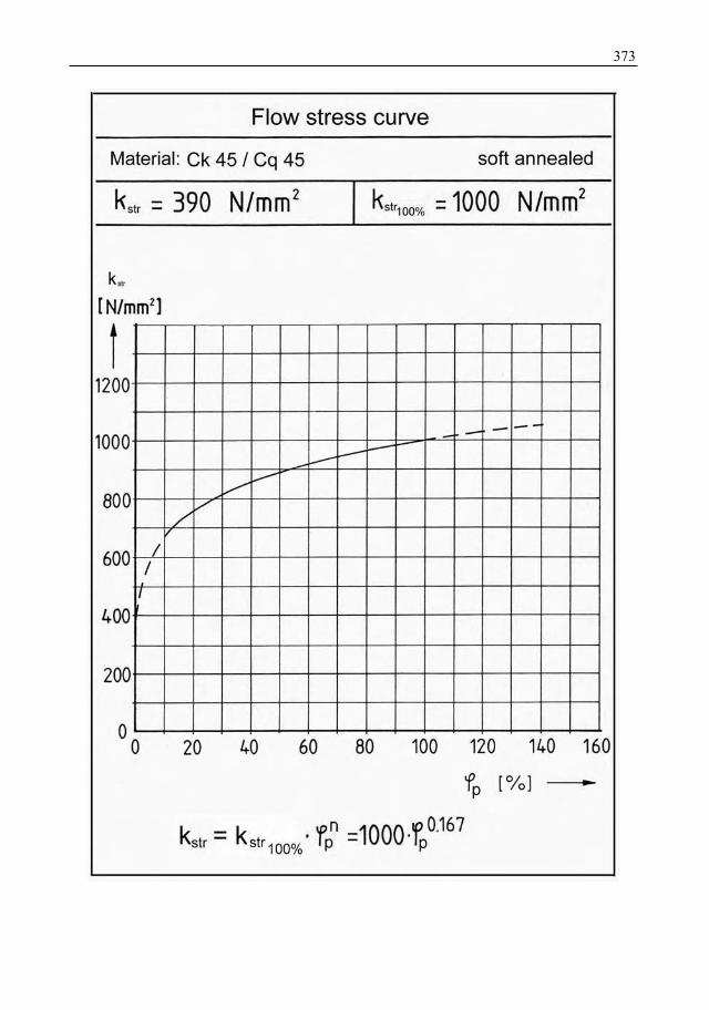
373
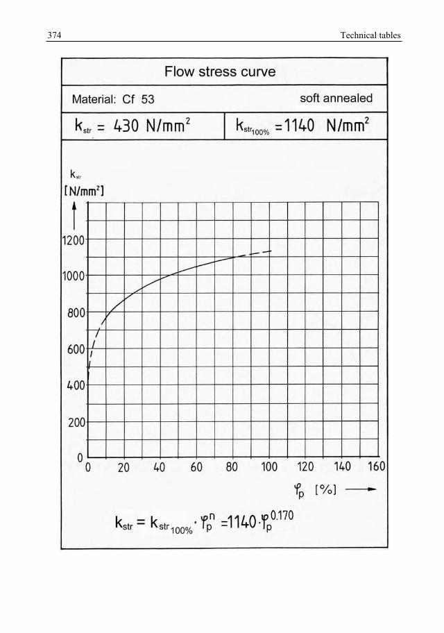
374 Technical tables
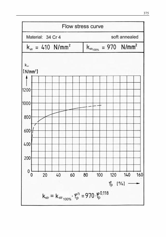
375

376 Technical tables
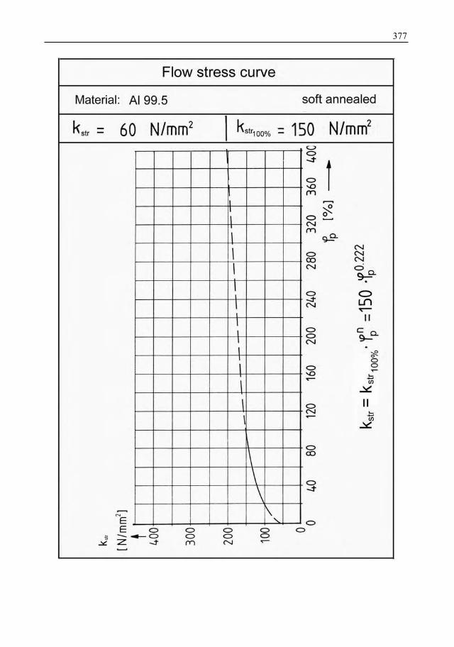
377
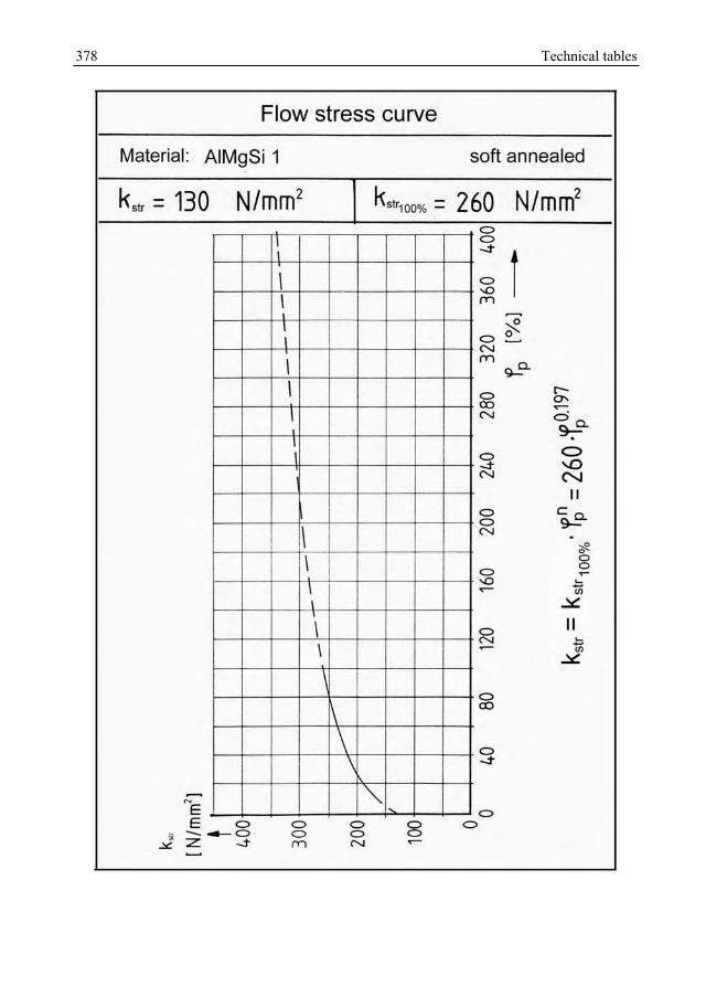
378 Technical tables
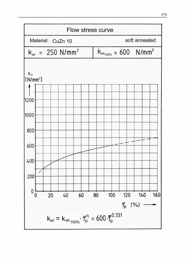
379
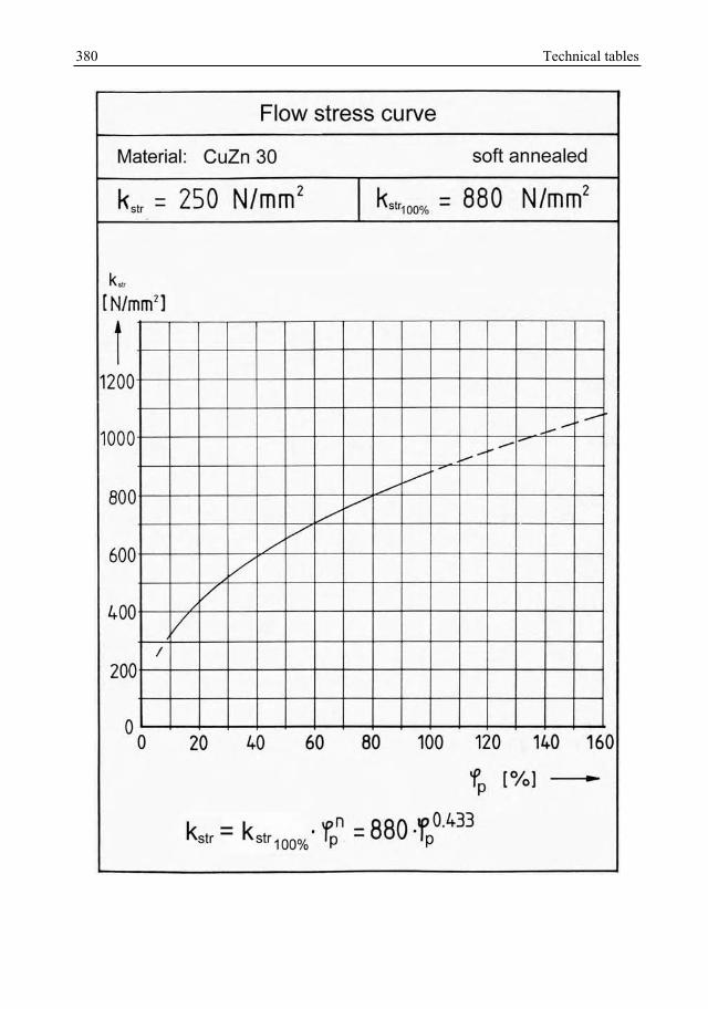
380 Technical tables

381
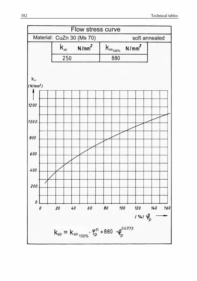
382 Technical tables
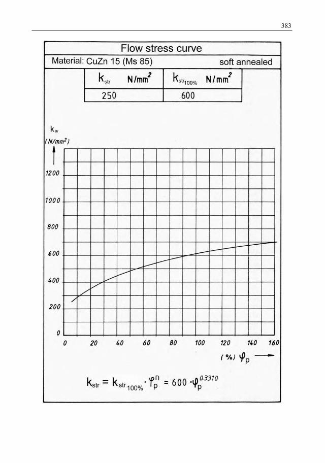
383

384 Technical tables
Table 2 Circumference and area of circles from 1 to 150 diameter
d Circumf. Area d Circumf. Area d Circumf. Area
1 3.1416 0.7854 51 160.22 2042.82 101 317.30 8 012 2 6.2832 3.1416 52 163.36 2123.72 102 320.44 8 171 3 9.4248 7.0686 53 166.50 2006.18 103 323.58 8 332 4 12.566 12.57 54 169.65 2290.22 104 326.73 8 495 5 15.708 19.63 55 172.79 2375.83 105 329.87 8 659 6 18.850 28.27 56 175.93 2463.01 106 333.01 8 825 7 21.991 38.48 57 179.07 2551.76 107 336.15 8 992 8 25.133 50.27 58 182.21 2642.08 108 339.29 9 161 9 28.274 63.62 59 185.35 2733.97 109 342.43 9 331 10 31.616 78.54 60 188.50 2827.43 110 345.58 9 503 11 34.588 95.03 61 191.64 2922.47 111 348.72 9 677 12 37.699 113.10 62 194.78 3019.07 112 351.86 9 852 13 40.841 132.73 63 197.92 3117.25 113 355.00 10 029 14 43.982 153.94 64 201.06 3216.99 114 358.14 10 207 15 47.124 176.71 65 204.20 3318.31 115 361.28 10 387 16 50.265 201.06 66 207.35 3421.19 116 364.42 10 568 17 53.407 226.98 67 210.49 3525.65 117 367.57 10 751 18 56.549 254.47 68 213.63 3631.68 118 370.71 10 936 19 59.690 283.53 69 216.77 3739.28 119 373.85 11 122 20 62.832 314.16 70 219.91 3848.45 120 376.99 1131021 65.973 346.36 71 223.05 3959.19 121 380.13 1149922 69.115 380.13 72 226.19 4071.50 122 383.27 1169023 72.257 415.48 73 229.34 4185.39 123 386.42 1188224 75.398 452.39 74 232.48 4300.84 124 389.56 12 076 25 78.540 490.87 75 235.62 4417.86 125 392.70 12 272 26 81.681 530.93 76 238.76 4536.46 126 394.84 12 469 27 84.823 572.56 77 241.90 4656.63 127 398.98 12 668 28 87.965 615.75 78 245.04 4778.36 128 402.12 12 868 29 91.106 660.52 79 248.19 4901.67 129 405.27 13 070 30 94.25 706.86 80 251.33 5026.55 130 408.41 13 273 31 97.39 754.77 81 254.47 5153.00 131 411.55 13 478 32 100.53 804.25 82 257.61 5281.02 132 414.69 13 685 33 103.67 855.30 83 260.75 5410.61 133 417.83 13 983 34 106.81 907.92 84 263.89 5541.77 134 420.97 14 103 35 109.96 962.11 85 267.04 5674.50 135 424.12 1431436 113.10 1017.88 86 270.18 5808.80 136 427.26 14 527 37 116.24 1075.21 87 273.32 5944.68 137 430.40 14 741 38 119.38 1134.11 88 276.46 6082.12 138 433.54 14 957 39 122.52 1194.59 89 279.60 6221.14 139 436.68 15 175 40 125.66 1256.64 90 282.74 6361.73 140 439.82 15 394 41 128.81 1320.2 91 285.88 6504 141 442.96 15 615 42 131.95 1385.44 92 289.03 6648 142 446.11 15 837 43 135.09 1452.20 93 292.17 6793 143 449.25 16 061 44 138.23 1520.53 94 295.31 6940 144 452.39 16 286 45 141.37 1590.43 95 298.45 7088 145 455.53 1651346 144.51 1661.90 96 301.59 7238 146 458.67 16 742 47 147.65 1734.94 97 304.73 7390 147 461.81 16 972 48 150.80 1809.56 98 307.88 7543 148 464.96 17 203 49 153.94 1885.74 99 311.02 7698 149 468.10 17 437 50 157.08 1963.50 100 314.16 7854 150 471.24 17 671

385
d Circumf. Area d Circumf. Area d Circumf. Area151 474.38 17 908 201 631.46 31731 251 788.54 49 481 152 477.52 18 146 202 634.60 32 047 252 791.68 49 876 153 480.66 18 385 203 637.74 32 365 253 794.82 50 273 154 483.81 18 627 204 640.88 32 685 254 797.96 50 671 155 486.95 18 869 205 644.03 33 006 255 801.11 51071156 490.09 19 113 206 647.17 33 329 256 804.25 51472157 493.23 19 359 207 650.31 33 654 257 807.39 51 875 158 496.37 19 607 208 653.45 33 979 258 810.53 52 279 159 499.51 19 856 209 656.59 34 307 259 813.67 52 685 160 502.65 20 106 210 659.73 34 636 260 816.81 53 093 161 505.80 20 358 211 662.88 34 967 261 819.96 53 502 162 508.94 20 612 212 666.02 35 299 262 823.10 53 913 163 512.08 20 867 213 669.16 35 633 263 826.24 54 325 164 515.22 21 124 214 672.30 35 968 264 829.38 54 739 165 518.36 21382 215 675.44 36 305 265 832.52 55 155 166 521.50 21642 216 678.58 36 644 266 835.66 55 572 167 524.65 21904 217 681.73 36 984 267 838.81 55 990 168 527.79 22 167 218 684.87 37 325 268 841.95 56 410 169 530.93 22 432 219 688.01 37 668 269 845.09 56 832 170 534.07 22 698 220 691.15 38 013 270 848.23 57 256 171 573.21 22 966 221 694.29 38 360 271 851.37 57 680 172 540.35 23 235 222 697.43 38 708 272 854.51 58 107 173 543.50 23 506 223 700.58 39 057 273 857.65 58 535 174 546.64 23 779 224 703.72 39 408 274 860.80 58 965 175 549.78 24 053 225 706.86 39 761 275 863.94 59 396 176 552.92 24 328 226 710.00 40 115 276 867.08 59 828 177 556.06 24 606 227 713.14 40 471 277 870.22 60 263 178 559.20 24 885 228 716.28 40 828 278 873.36 60 699 179 562.35 25 165 229 719.42 41 187 279 876.50 61 136 180 565.49 25 447 230 722.57 41548 280 879.65 61 575 181 568.63 25 730 231 725.71 41910 281 882.79 62 016 182 571.77 26 016 232 728.85 42 273 282 885.93 62 458 183 574.91 26 302 233 731.99 42 638 283 889.07 62 902 184 578.05 26 590 234 735.13 43 005 284 892.21 63 347 185 581.19 26 880 235 738.27 43 374 285 895.35 63 794 186 584.34 27 172 236 741.42 43 744 286 898.50 64 242 187 587.48 27 465 237 744.56 44 115 287 901.64 64 692 188 590.62 27 759 238 747.70 44 488 288 904.78 65 144 189 593.76 28 055 239 750.84 44 863 289 907.92 65 597 190 596.90 28 353 240 753.98 45 239 290 911.06 66 052 191 600.04 28 652 241 757.12 45 617 291 914.20 66 508 192 603.19 28 953 242 760.27 45 996 292 917.35 66 966193 606.33 29 255 243 763.41 46 377 293 920.49 67 426 194 609.47 29 559 244 766.55 46 759 294 923.63 67 887 195 612.61 29 865 245 769.69 47 144 295 926.77 68 349 196 615.75 30 172 246 772.83 47 529 296 929.91 68 813 197 618.89 30 481 247 775.97 47 916 297 933.05 69 279 198 622.04 30 791 248 779.11 48 305 298 936.19 69 746 199 625.18 31 103 249 782.26 48 695 299 939.34 70 215 200 628.32 31 416 250 785.40 49 087 300 942.48 70 686
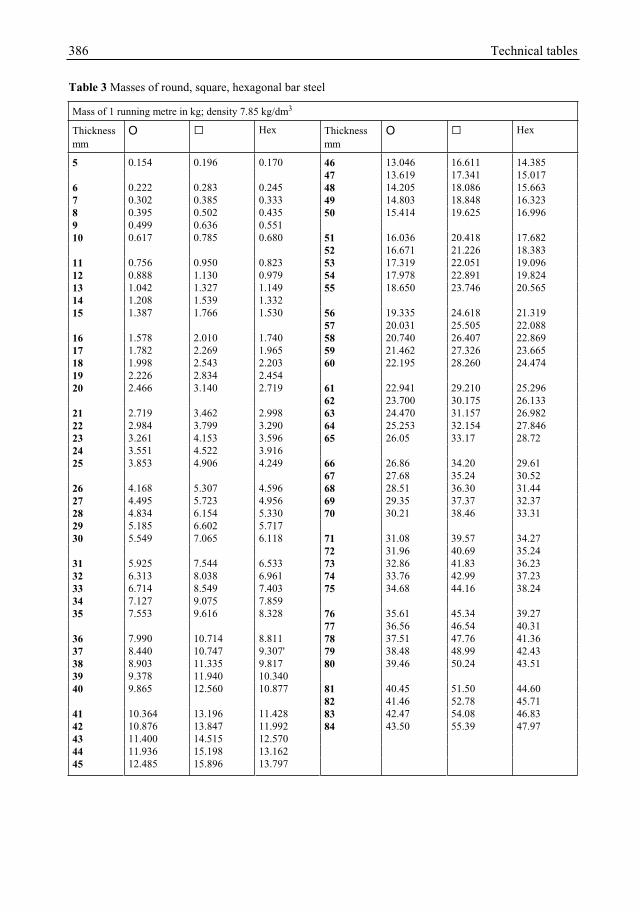
386 Technical tables
Table 3 Masses of round, square, hexagonal bar steel
Mass of 1 running metre in kg; density 7.85 kg/dm3
Thickness mm
O Hex Thickness mm
O Hex
5 0.154 0.196 0.170 46 13.046 16.611 14.385 47 13.619 17.341 15.017
6 0.222 0.283 0.245 48 14.205 18.086 15.663 7 0.302 0.385 0.333 49 14.803 18.848 16.323 8 0.395 0.502 0.435 50 15.414 19.625 16.996 9 0.499 0.636 0.551 10 0.617 0.785 0.680 51 16.036 20.418 17.682
52 16.671 21.226 18.383 11 0.756 0.950 0.823 53 17.319 22.051 19.096 12 0.888 1.130 0.979 54 17.978 22.891 19.824 13 1.042 1.327 1.149 55 18.650 23.746 20.565 14 1.208 1.539 1.332 15 1.387 1.766 1.530 56 19.335 24.618 21.319
57 20.031 25.505 22.088 16 1.578 2.010 1.740 58 20.740 26.407 22.869 17 1.782 2.269 1.965 59 21.462 27.326 23.665 18 1.998 2.543 2.203 60 22.195 28.260 24.474 19 2.226 2.834 2.454 20 2.466 3.140 2.719 61 22.941 29.210 25.296
62 23.700 30.175 26.133 21 2.719 3.462 2.998 63 24.470 31.157 26.982 22 2.984 3.799 3.290 64 25.253 32.154 27.846 23 3.261 4.153 3.596 65 26.05 33.17 28.72 24 3.551 4.522 3.916 25 3.853 4.906 4.249 66 26.86 34.20 29.61
67 27.68 35.24 30.52 26 4.168 5.307 4.596 68 28.51 36.30 31.44 27 4.495 5.723 4.956 69 29.35 37.37 32.37 28 4.834 6.154 5.330 70 30.21 38.46 33.31 29 5.185 6.602 5.717 30 5.549 7.065 6.118 71 31.08 39.57 34.27
72 31.96 40.69 35.24 31 5.925 7.544 6.533 73 32.86 41.83 36.23 32 6.313 8.038 6.961 74 33.76 42.99 37.23 33 6.714 8.549 7.403 75 34.68 44.16 38.24 34 7.127 9.075 7.859 35 7.553 9.616 8.328 76 35.61 45.34 39.27
77 36.56 46.54 40.31 36 7.990 10.714 8.811 78 37.51 47.76 41.36 37 8.440 10.747 9.307' 79 38.48 48.99 42.43 38 8.903 11.335 9.817 80 39.46 50.24 43.51 39 9.378 11.940 10.340 40 9.865 12.560 10.877 81 40.45 51.50 44.60
82 41.46 52.78 45.71 41 10.364 13.196 11.428 83 42.47 54.08 46.83 42 10.876 13.847 11.992 84 43.50 55.39 47.97 43 11.400 14.515 12.570 44 11.936 15.198 13.162 45 12.485 15.896 13.797
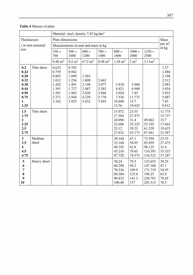
387
Table 4 Masses of plate
Material: steel, density 7.85 kg/dm3
Plate dimensions Measurements in mm and mass in kg
530760
5001000
6001200
7001400
8001600
10002000
12502500
Thicknesses s in min nominal size
0.40 m2 0.5 m2 0.72 m2 0.98 m2 1.28 m2 2 m2 3.11m2
Mass per m2
in kg
0.20.240.280.320.380.440.500.751
1.25
Thin sheet 0.6320.7590.8851.0121.2021.3911.5812.3713.162
0.7850.9421.0991.2561.4911.7271.9622.9443.925
1.5831.8092.1482.4872.8264.2395.652
2.4623.0773.3853.8465.7707.693
3.818 4.421 5.024 7.536 10.04812.56
5.966 6.908 7.85 11.77515.719.625
1.57 1.884 2.198 2.512 2.983 3.454 3.925 5.887 7.85 9.812
1.51.752
2.252.52.75
Thin sheet 15.07217.58420.09622.60825.1227.632
23.5527.47531.435.32539.2543.175
49.06255.19561.32867.461
11.77513.73715.717.66219.62521.587
3 3.5 4 4.54.75
Mediumsheet
30.14435.16840.19245.21647.728
47.154.9562.870.6574.575
73.59485.85998.125110.391116.523
23.5527.47531.435.32537.287
5 6 7 8 910
Heavy sheet 50.2460.28870.33680.38490.432100.48
78.594.2109.9125.6141.3157
122.655147.188171.719196.25220.781245.312
39.2547.154.9562.870.6578.5
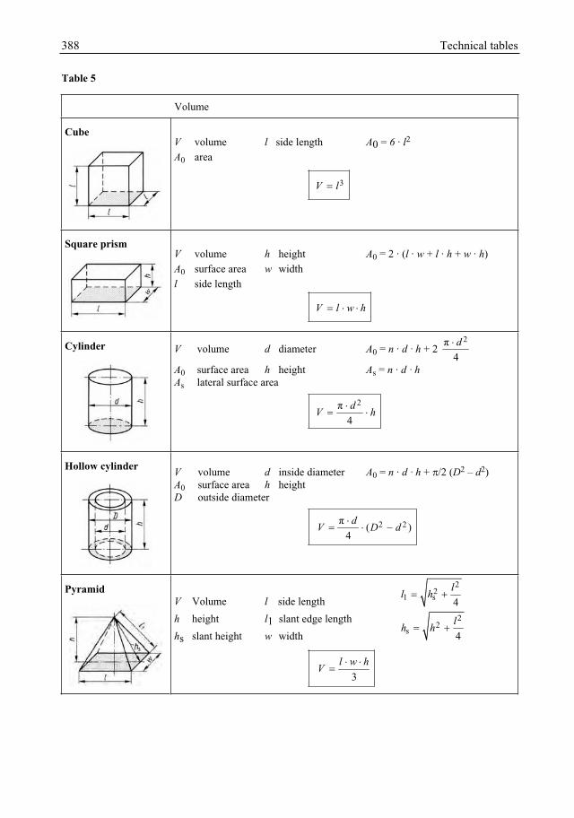
388 Technical tables
Table 5
Volume
Cube V volume l side length A0 = 6 · l2
A0 area
3V l
Square prismV volume h height A0 = 2 · (l · w + l · h + w · h)A0 surface area w widthl side length
V l w h
Cylinder V volume d diameter A0 = n · d · h + 2 2
4d
A0 surface area h height As = n · d · hAs lateral surface area
2
4dV h
Hollow cylinder V volume d inside diameter A0 = n · d · h + /2 (D2 – d2)A0 surface area h heightD outside diameter
2 2( )4
dV D d
Pyramid V Volume l side length h height l1 slant edge length hs slant height w width
3l w hV
22
1 s
22
s
4
4
ll h
lh h

389
Table 5 (continued)
Cone V volume h heightAM lateral surface area hs slant height d diameter
2
4 3d hV
sM 2
d hA
22
s 4dh h
V volume h heightA1 lower base area hs slant height A2 upper base area l1, l2 side length w1, w2width
A1 = l1 · w1A2 = l2 · w2
21 2
s 2 2l lh h
Pyramidal frustum
1 2 1 2( )3hV A A A A
V volumeAs lateral surface area D bottom diameter
d top diameter h heighths slant height
ss
22
s
( )2
2
hA D d
D dh h
Cone frustum
2 2( )12
hV D d D d
V volumeA0 surface area
d sphere diameter A0 = · d 2 Sphere
3
6hV
V volumeAs lateral surface areaA0 surface area
d sphere diameter d1 small diameterh height
As = · d · h A0 = · h · (2 · d – h)
Spherical segment
22 3d hV h

390 Technical tables
Table 6 Types and strengths of sheets less than 3 mm thick
Shortdesignation
Steelmak-ingprocess
Castingprocess
C%
N/mm2 ReN/mm2
N/mm2 Failure strain A %
Properties Old designation
T St 1001 to 03
T 0.15 280 to 500 – 300 to 350 – Basic quality, easy to form
–
St 1001 to 03
M or Y 0.15 280 to 500 – 300 to 350 – Basic quality, easy to form
St II 23 to St IV 23
WU St 1203to 05
W R 0.10 270 to 410 – 240 to 300 24 Drawing quality –
U St 1203 to 05
M or Y R 0.10 270 to 410 – 240 to 300 24 Drawing quality St V 23 to St VI 23
U St 1303 to 05
U R 0.10 270 to 370 270 240 to 300 27 Deep drawing quality
–
R St 1303 to 05
M or Y K 0.10 270 to 370 270 240 to 300 27 Deep drawing quality
St VII 23
U St 1404 to 05
M or Y R 0.10 280 to 350 240 250 to 320 30 Extra deep draw-ing quality
St VII 23
RR St 1404 to
M or Y FK 0.10 270 to 350 240 250 to 320 30 Extra deep draw-ing quality
St VIII 23

391
Table 7 Low-carbon unalloyed steels for screws and bolts, nuts and rivets. Guaranteed chemical compo-sition
Steel grade Chemical composition in wt %
Short name Materialnumber
Deoxida-tiontype1) C2) Si Mn P S
USt 36 1.0203 R 0.143) traces 0.25 to 0.50 0.050 0.050
UQSt 36 1.0204 R 0.143) traces 0.25 to 0.50 0.040 0.040
RSt 36 1.0205 K 0.143) 0.30 0.25 to 0.50 0.050 0.050
USt 384) 1.02174) R 0.195) traces 0.25 to 0.50 0.050 0.050
UQSt 384) 1.02244) R 0.195) traces 0.25 to 0.50 0.040 0.040
RSt 38 1.0223 K 0.195) 0.30 0.25 to 0.50 0.050 0.050
U 7 S 66) 1.07086) U6) 0.10 traces 0.30 to 0.60 0.050 0.04 to 0.08
U 10 S 107) 1.07027) U7) 0.15 traces 0.30 to 0.60 0.050 0.08 to 0.12
1) R rimmed, K killed (including semikilled). 2) On ordering a lower maximum carbon content can be agreed on; in this case, however, the minimum tensile
strength value according to Table 2 no longer applies.3) For dimensions above 22 mm the maximum content is 0.18% C. 4) In the next version of this norm, this steel may be deleted subject to verification (see annotations). 5) For dimensions above 22 mm the maximum content is 0.22% C. 6) When ordering, the killed steel R 7 S 6 (material number 1.0709) with max. 0.40% Si and an upper manga-
nese level of 0.80% may be delivered on agreement. 7) When ordering, the killed steel R 10 S 10 (material number 1.0709) with max. 0.40% Si and an upper man-
ganese level of 0.80% may be delivered on agreement.

392 Technical tables
Table 8 Selection of steels suitable for cold extrusion
Short designation of material Material no. Notes
UQSt 36-2 (Muk 7) Ma 8 (Mbk 6)
1.0204 1.0303
Later treatment possible if necessary. Steels with no further heat treatment
Steels with particularly low C content = 0.05%
Only relevant magnetic properties affect selection.
Steels for later heat treatment
unalloyed Ck 10 Cq 15
1.1121 1.1132
Also C10, C15 and Ck 15 if required Case hard-ened steels
alloyed 15 Cr 3 16 MnCr 5 20 MnCr 5 15 CrNi 6 17 CrNiMo 6 20 MoCr 4
1.7015 1.7131 1.7147 1.5919 1.6587 1.7321
C contents generally below 0.25%; the core strength is heavily influenced by the alloy elements.
unalloyed Cq 22
Cq 35 Cq 45
1.1152
1.1172 1.1197
Quenchedand tempered steels
alloyed 34 Cr 4 37 Cr 4 41 Cr 4 25 CrMo 4 34 CrMo 4 42 CrMo 4 34 CrNiMo 6
1.7033 1.7034 1.7035 1.7218 1.7220 1.7225 1.6582
Also C 35 and C 45 if necessary
Quenching and tempering can be used to reach the tensile strength required for a certain application, with sufficient toughness. The hardenability depends upon the composition; with unalloyed materials the C and Mn contents determine the material properties which can be achieved when quenching and tempering (oil or water hardening must be agreed on when ordering). With high degrees of deformation, high strengths can also be achieved with no subsequent heat treatment. Steels with a guaranteed Cr content, e.g. 38 Crl, 46 Crl, 38 Cr2, 46 Cr2, are easier to quench and temper but do not necessarily have a better deformability than steels with no guaranteed Cr content; for this reason they are not listed in this table. A special check should always be made to see whether they need to be used.
ferritic X 7 Cr 13 X 10 Cr 13 X 22 CrNi 17 X 12 CrMoS 17
1.4000 1.4006 1.4057 1.4104
heat treatableheat treatableheat treatableheat treatable
Corrosion-resistantsteels
austenitic X 5 CrNi 18 9 X 2 CrNi 18 9 X 2 NiCr 18 16 X 5 CrNiMo 18 10 X 10 CrNiTi 18 9 X 10 CrNiMoTi 18 10 X 2 CrNiMo 18 12
1.4301 1.4306 1.4321 1.4401 1.4541 1.4571 1.4435
with higher degrees of deformation
in special cases
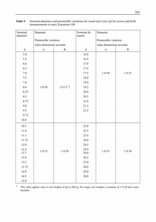
393
Table 9 Nominal diameters and permissible variations for round steel wire rod for screws and bolts (measurements in mm), Euronorm 108
Nominal diameter
Diameter Nominal di-ameter
Diameter
Permissible variation Permissible variation when dimensions accurate when dimensions accurate
d A B d A B
5.0 16.05.5 16.56.0 17.06.5 17.47.0 17.5 0.30 0.25 7.5 18.07.8 19.08.0 0.20 0.15 1) 19.58.25 20.08.5 20.58.75 21.09.0 21.39.5 21.59.75
10.0
10.5 22.011.0 22.511.5 23.011.75 24.012.0 24.512.512.7 0.25 0.20 25.0
26.0 0.35 0.30
13.0 26.513.5 27.013.75 28.014.0 29.014.5 30.015.0
1) This value applies only to coil weights of up to 200 kg. For larger coil weights a variation of 0.20 mm is per-missible.

394 Technical tables
Tab
le 1
0 To
olin
g m
ater
ials
Mat
eria
l To
olin
g ty
pe a
nd H
RC
ass
embl
y ha
rdne
ss (m
ean
valu
es)
Shea
ring
Dra
win
gSt
ampi
ngB
endi
ngC
old
sink
ing
Extru
sion
Shrin
king
Ups
ettin
gIm
pres
sion
die
Mat
eria
l nu
mbe
rD
esig
natio
nM
ax.
HR
Cha
rd-
ness
Stre
ss
Pch
Die
Pc
h D
ie
Pch
Die
Pc
h D
ie
Pch
–Pc
h D
ie
1st ring
2nd ring
Pch
Die
Upp
.Lo
w.
1530
C 8
5 W
1
6361
6161
6161
6161
61
1540
C 1
00 W
1
6462
6262
6262
6262
6262
62
1550
C 1
10 W
1
6562
6262
6262
6262
6262
1620
C 7
0 W
2
6360
60
1640
C 1
00 W
2
6562
6262
6262
62
1650
C 1
15 W
2
6562
6262
62
1660
C 1
30 W
2
65
nor-
mal
6262
2025
110
Cr 2
65
5959
2056
90 C
r 65
6262
6262
6262
2057
105
Cr 4
65
6161
61
2060
105
Cr 5
65
6161
2063
145
Cr 6
65
6161
6161
6161
6161
2067
100
Cr 6
64
6363
6363
6363
2080
X 2
10 C
r 12
6562
6262
6262
6262
6262
6262
2127
105
MnC
r 4
65
high
6060
6060
6060
6060

395
Tab
le 1
0 (c
ontin
ued)
2243
61 C
rSiV
5
6054
54
2248
38 S
iCrV
8
5452
52
2249
45 S
iCrV
6
5854
54
2323
45 C
rMoV
67
5755
5555
5555
5555
55
2419
105
WC
r 6
6461
6161
6161
6161
61
2436
X 2
10 C
rW 1
2 65
6161
6161
6161
6161
2541
35 W
CrV
7
5853
53
2542
45 W
CrV
7
5853
53
2547
45 W
CrV
77
5855
55
2550
60 W
CrV
7
6058
5858
5858
5858
5858
58
2567
X 3
0 W
CrV
53
5252
5250
50
2603
45 C
rMoW
58
5350
50
2713
55 N
iCrM
oV 6
48
4648
48
2714
56 N
iCrM
oV 7
48
4646
2721
50 N
iCr 1
3 59
5555
5555
5555
5555
6055
55
2767
X 4
5 N
iCrM
o 4
5050
5050
5050
5058
48
2842
90 M
nV 8
64
6060
2080
X 2
10 C
r 12
65v. hi
gh62
6262
6363
62
2201
62 S
iMnC
r 4
6560
6060
6060
6060
6060

396 Technical tables
Tab
le 1
0 (c
ontin
ued)
Mat
eria
l To
olin
g ty
pe a
nd H
RC
ass
embl
y ha
rdne
ss (m
ean
valu
es)
Shea
ring
Dra
win
gSt
ampi
ngB
endi
ngC
old
sink
ing
Extru
sion
Shrin
king
Ups
ettin
gim
pres
s. di
eM
ate-
rial
No.
DIN
1700
6M
ax.
HR
Cha
rd-
ness
Stre
ss
Pch
Die
Pc
h D
ie
Pch
Die
Pc
h D
ie
Pch
–Pc
h D
ie
1st ring
2nd ring
Pch
Die
Upp
.Lo
w.
2343
X 3
8 C
rMoV
51
5652
52
2363
X10
0 C
rMoV
5-1
64
6161
6161
2365
X 3
2 C
rMoV
33
5549
49
2436
X 2
10 C
rW 1
2 65
6060
60
2601
X 1
65 C
rMoV
12
6460
6060
6062
2884
X 2
10 C
rCoW
12
64
v. high
6161

397T
able
28.
2 St
rain
rate
= f
(r a
nd in
itial
hei
ght h
0 of t
he b
lank
)
Mac
hine
R
am im
pact
velo
city
in
m/s
0h
(s
–1)
for h
0=
(mm
)
h 05
1020
3040
5010
015
020
025
030
040
050
0
Dro
p ~
5.6
1120
560
280
187
140
112
5637
.328
22.4
18.6
1411
.2
Dou
ble-
actin
g6
1200
600
300
200
150
120
6040
3024
2015
12
Hammer
Cou
nter
blow
~12
2400
1200
600
400
300
240
120
8060
4840
3024
Scre
w p
ress
1.
020
010
050
33.3
2520
106.
75.
04.
03.
32.
52.
0
Hyd
raul
ic p
ress
es
0.25
5025
12.5
8.3
6.2
52.
51.
71.
251.
00.
830.
60.
5
Cra
nk p
r. w
here
=
30
º 0.
612
060
3020
1512
6.0
4.0
3.0
2.4
2.0
1.5
1.2
Tables for hot and semi-hot forming
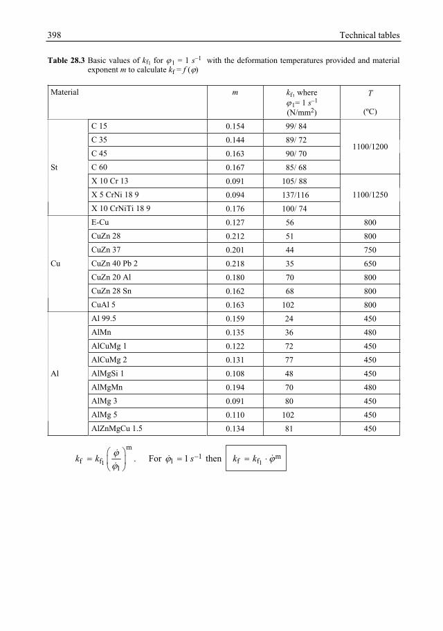
398 Technical tables
Table 28.3 Basic values of kf1 for 1 = 1 s–1 with the deformation temperatures provided and material exponent m to calculate kf = f ( )
Material m kf1 where 1= 1 s–1
(N/mm2)
T
(ºC)
C 15 0.154 99/ 84 C 35 0.144 89/ 72 C 45 0.163 90/ 70 C 60 0.167 85/ 68
1100/1200
X 10 Cr 13 0.091 105/ 88 X 5 CrNi 18 9 0.094 137/116
St
X 10 CrNiTi 18 9 0.176 100/ 74
1100/1250
E-Cu 0.127 56 800CuZn 28 0.212 51 800CuZn 37 0.201 44 750CuZn 40 Pb 2 0.218 35 650CuZn 20 Al 0.180 70 800CuZn 28 Sn 0.162 68 800
Cu
CuAl 5 0.163 102 800Al 99.5 0.159 24 450AlMn 0.135 36 480AlCuMg 1 0.122 72 450AlCuMg 2 0.131 77 450AlMgSi 1 0.108 48 450AlMgMn 0.194 70 480AlMg 3 0.091 80 450AlMg 5 0.110 102 450
Al
AlZnMgCu 1.5 0.134 81 450
1
m
f f1
.k k For 11 1 s then 1mf fk k

399
Table 28.4 Flow stress depending on the forming speed for the forging temperature T = constant
Material T(ºC)
f ( )k f for T = const. kf in N/mm2
1(s–1)
2(s–1)
4(s–1)
6(s–1)
10(s–1)
20(s–1)
30(s–1)
40(s–1)
50(s–1)
C 15 1200 84 93 104 110 120 133 141 145 153C 35 1200 72 80 88 93 100 111 118 122 126C 45 1200 70 78 88 94 102 114 122 128 132C 60 1200 68 76 86 92 100 112 120 126 131X 10Cr 13 1250 88 94 100 104 109 116 120 123 126X 5CrNi 18 9 1250 116 124 132 137 144 154 160 164 168
X10CrNiTi189 1250 74 84 94 101 111 125 135 142 147E-Cu 800 56 61 67 70 75 82 86 89 92CuZn 28 800 51 59 68 75 83 96 105 111 117CuZn 37 750 44 51 58 63 70 80 87 92 97CuZn 40 Pb 2 650 35 41 47 51 58 67 73 78 82CuZn 20 Al 800 70 79 90 97 106 120 129 136 142CuZn 28 Sn 800 68 76 85 91 99 110 118 124 128
CuA1 5 800 102 114 128 137 148 166 178 186 193Al 99.5 450 24 27 30 32 35 39 41 43 45AlMn 480 36 40 44 46 49 54 57 59 61AlCuMg 1 450 72 78 85 90 95 104 109 113 116AlCuMg 2 450 77 84 92 97 104 114 120 125 129AlMgSi 1 450 48 52 56 58 62 66 69 71 73AlMgMn 480 70 80 92 99 109 125 135 143 150AlMg 3 450 80 85 91 94 99 105 109 112 114AlMg 5 450 102 110 119 124 131 142 148 153 157AlZnMgCu 1.5 450 81 89 98 103 110 121 128 133 137

400 Technical tables
70(s–1)
100(s–1)
150(s–1)
200(s–1)
250(s–1)
300(s–1)
161 170 181 189 196 201
133 140 148 154 159 164
140 148 158 166 172 177
138 147 157 164 171 176
130 134 139 143 145 148
173 179 186 191 195 198
156 166 179 188 196 202
96 101 106 110 113 116
126 135 148 157 164 171
103 111 120 128 133 138
88 96 104 111 117 121
150 160 172 182 189 195
135 143 153 160 166 171
204 216 231 242 251 258
47 50 53 56 58 59
64 67 71 74 76 78
121 126 133 137 141 144
134 141 148 154 159 163
76 79 82 85 87 89
160 171 185 196 204 212
118 122 126 130 132 134
163 169 177 183 187 191
143 150 159 165 170 174
Bibliography
1 Books
1.1 Fundamental principles 1 W. Dahl, R. Kopp, O. Pawelski, Umformtechnik, Plastomechanik und Werkstoffkunde, Verlag Stahle-
isen GmbH, Düsseldorf (1993) 2 Bergmann, Werkstofftechnik Teil 1 und 2, Carl Hanser Verlag, Munich/Vienna (2000) 3 Lange, Lehrbuch der Umformtechnik, Volume 1: Grundlagen, Volume 4: Sonderverfahren, Prozess-
simulation, Werkzeugtechnik, Produktion, Springer Verlag, Berlin/Heidelberg (1993)
1.2 Bulk forming 4 Lange, Lehrbuch der Umformtechnik, Grundlagen, Springer Verlag, Berlin/Heidelberg (2002) 5 Spur, Stöferle, Handbuch der Fertigungstechnik, Volumes 2/1 and 2/2: Umformen, Carl Hanser
Verlag, Munich/Vienna (1985) 6 W. König, Fertigungsverfahren, Volume 4: Massivumformung, VDI-Verlag, Düsseldorf (1996) 7 Schal, Fertigungstechnik 2, Massivumformen und Stanzen, Verlag Handwerk und Technik, Hamburg
(1995)8 Kleiner, Schilling, Prozesssimulation in der Umformtechnik, Teubner Verlag, Stuttgart (1994) 9 Pöhlandt, Werkstoffe und Werkstoffprüfung für die Kalt-Massivumformung, Expert-Verlag, Essen
(1994)10 L Budde, R. Pilgrim, Stanznieten und Durchsetzfügen, Die Bibliothek der Technik, Vol. 115, Verlag
moderne industrie, Landsberg (1995) 11 Wojahn and Breitkopf, Übungsbuch Fertigungstechnik – Urformen, Umformen. Vieweg Verlag,
Braunschweig/Wiesbaden (1996) 12 N. Becker, Weiterentwicklung von Verfahren zur Aufnahme von Fließkurven im Bereich hoher Um-
formgrade, Springer Verlag, Berlin/Heidelberg (1994) 13 G. Du, Ein wissensbasiertes System zur Stadienplanermittlung beim Kaltmassivumformen, Springer
Verlag, Berlin/Heidelberg (1991)
1.3 Sheet metal forming 14 Lange, Lehrbuch der Umformformtechnik, Volume 3: Blechbearbeitung, Springer Verlag, Ber-
lin/Heidelberg (1990) 15 G. Spur, T. Stöferle, Handbuch der Fertigungstechnik, Volume 2/3: Umformen – Zerteilen, Carl
Hanser Verlag, Munich/Vienna (1985) 16 W. König, Fertigungsverfahren, Volume 5: Blechumformung, VDI-Verlag, Düsseldorf (1990) 17 Hellwig, Semlinger, Spanlose Fertigung – Stanzen, Vieweg Verlag, Braunschweig/Wiesbaden (2001) 18 Oehler, Kaiser, Schnitt-, Stanz- und Ziehwerkzeuge, Springer Verlag, Berlin/Heidelberg (1993) 19 Oehler, Panknin, Schneid- und Stanzwerkzeuge, Springer Verlag, Berlin/Heidelberg (1995) 20 Schilling, Finite-Elemente-Analyse des Biegeumformens von Blech, Verlag Stahleisen, Düsseldorf
(1992)21 A.H. Fritz, G. Schulze, Fertigungstechnik, Springer Verlag, Berlin/Heidelberg (2001)
402 Bibliography
1.4 Metal forming machines 22 Wagner, Pahl, Mechanische und Hydraulische Pressen, VDI-Verlag, Düsseldorf (1992) 23 Schuler GmbH, Göppingen, Handbuch der Umformtechnik, Springer Verlag, Berlin/Heidelberg (2003)24 M. Weck, Werkzeugmaschinen Volumes 1-5, Maschinenarten, Konstruktion und Berechnung,
Automatisierung and Steuerungstechnik. Springer Verlag, Berlin/Heidelberg (2001) 25 H. Tschätsch, Werkzeugmaschinen in der spanlosen und spangebenden Formgebung, Carl Hanser
Verlag, Munich (2003)
1.5 Scientific publications U. Helfritzsch, Verfahren und Maschinen für das Walzen von Verzahnungen, research report for the Fraunhofer Institute for Machine Tools and Forming Technology, Chemnitz, Jan. 2001 T. Nakagawa, K. Nakamura, H. Amino, Various Applications of Hydraulic Counter-Pressure Deep-Drawing, Journal of Materials Processing Technology, vol. 71, pp 160, 1997 J. Dietrich et al. Vergleichende Untersuchung zur schnellen Fertigung von Umformwerkzeugen für Proto-typen (Rapid-Die-Making RDM), 6. Sächsische Fachtagung Umformtechnik, Tagungsband pp 288-303 (1999)M. Schmiedchen, Tür kreativ (Außenhochdruckumformung im Karosseriebau), dissertation, Dresden University of Applied Sciences, Germany (2000) R. Neugebauer, R. Mauermann, S. Dietrich, Spot-Joining – New technologies in the field of joining by forming, 7th International Conference on Technology of Plasticity, Vol. 2, Yokohama, Oct. 27th-Nov. 1st
2002R. Mauermann, S. Dietrich, Entwicklungsfortschritte beim matrizenlosen Clinchen und Nietclinchen, 2. Europäische Automobilkonferenz „Fügen im Automobilleichtbau“, Bad Nauheim, 8/9 April 2003 R. Neugebauer, M. Putz, Hydroforming in Prozessketten für Karosseriekomponenten, 3. Chemnitzer Karosseriekolloquium, Chemnitz 25/26.9.2002, Tagungsband (ISBN: 3-928921-80-0) R. Neugebauer, H. Bräunlich, Erhöhung der Produktionsstabilität durch Prozessregelung beim Tiefzie-hen, EFB-Kolloquium “Prozessoptimierung in der Blechumformung”, Fellbach 13/14.3.2001, EFB con-ference proceedings T21 L. Klose, H. Bräunlich, Erweiterung der umformtechnischen Grenzen durch vibrationsüberlagerten Tie-fziehprozess, Studiengesellschaft Stahlanwendung e.V., Dokumentation Forschung für die Praxis P383 L. Klose, V. Kräusel, P. Kügler, Innovationen auf dem Gebiet der Umform- und Schneidwerkzeuge, “Der Schnitt- und Stanz Werkzeugbau”, 5/2001 R. Neugebauer, S. Pannasch, B. Lorenz, Optimierung von Verfahren und Anlagen für eine durchgängige Prozesskette beim Schmieden, 4. Sächsische Fachtagung Umformtechnik organised by the Fraunhofer Institute for Machine Tools and Forming Technology, Chemnitz, 5/6.11.1997, conference proceedings R. Mauermann, Umformendes Fügen (see Chapter 20). Extract from the 2003 research report by the Fraunhofer Institute for Machine Tools and Forming Technology, Chemnitz U. Klemens, O. Hahn, Nietsysteme: Verbindungen mit Zukunft, joint editors: Interessengemeinschaft Umformtechnisches Fügen and Laboratorium für Werkstoff- und Fügetechnik, Paderborn University O. Hahn, U. Klemens, Fügen durch Umformen. Nieten und Durchsetzfügen – Innovative Verbindungsver-fahren für die Praxis. Studiengesellschaft Stahlanwendung e.V., Dokumentation 707, Düsseldorf, Verlag und Vertriebsgesellschaft Stahlanwendung mbH 1996, ISBN 3-930621-56-8 bedingungen, Teil 2

Index
AAir bending 194 Automatic tool change
systems 362
BBend radius 196 Bending brakes 207 Bending machines 205 Bending machines, three-
roller 209 Bibliography 403 Blank holder area 155 Blank holder force 156 Blank size, determining
during bending 198 Blank size, determining
during deep drawing axisymmetric parts 143 rectangular parts 148
Blanking 218 Blanking, fine 241 Bolt, production of a 44 Break clearance 225 Bulk forming 15
CCentroid of a line 222 Characteristic triangles 142 Classification, shape 49 Clinching 250 Clutches for presses 302 Clutches, press
non-positive friction clutches 302
positive driver clutches302
Coining 86 Cold hubbing 77 Cold hubbing presses 83 Continuous work capacity
310Conveyor, vibrating 348 Counterblow hammers 271 Crank presses 295 Crank presses, press force of
305
DDeep drawing 14 Deep drawing 141
sheet hydroforming 174 tube hydroforming 179
Deep drawing steps axisymmetric parts 152 rectangular drawn parts153
Deep drawing transfer presses 325
Deep drawing, stress distri-bution during 143
Defects during processing bending 204 cold hubbing 83 deep drawing 167 extrusion 44 impression-die forging 136
upset forging 27 Deformability 11 Deformation resistance 10 Deformation, degree of 11
cold hubbing 78 extrusion 113 extrusion 35 impression-die forging 129
ironing 91 tube drawing 107 upset forging 20 wire drawing 96
Degree of deformation 11 Die bending 199 Die edge curvature 159Die, forging 134 Double-acting hammer
267Draw ratio 158 Drawing clearance 15 Drawing presses 321 Drawing ring dimensions
152Drawing without a blank
holder 185
Drives eccentric and crank presses 300
hydraulic presses 318 knuckle-joint and toggle presses 313
screw presses 275 Drop hammers 266
EEccentric presses
gap-frame 295 open-back 297 straight-side 297
Edge cutter 234 Elastic deformation 7 Embossing 212 Embossing 86, 212 Example calculations
bending 204 blanking 238 cold hubbing 84 deep drawing 16 embossing 89, 217 extrusion 121 extrusion 44 impression-die forging 137
ironing 93 thread rolling 63 tube drawing 108 upset forging 27 wire drawing 103
Exercises bending 211 cold hubbing 85 deep drawing 161 embossing 90, 217 extrusion 122 extrusion 55 impression-die forging 139
ironing 94 surface treatment 17 terms and parameters 14 thread rolling 68

404 Index
tube drawing 108 upset forging 32 wire drawing 104
Extrusion 109 Extrusion 33 Extrusion 33 Extrusion presses 120
FFeed devices 345 Feed system, gripper 346 Feed system, roll 345 Feed system, workpiece
345Fine blanking 241 Fine blanking press, auto-
matic 245 Flexible manufacturing
systems 351 Flow stress 8 Flow stress curves 9, 368 Folded profiles 208 Force calculation
bending 199 blanking 220 cold hubbing 78 deep drawing 154 deep drawing without a blank holder 173
embossing 87, 215 extrusion 114 extrusion 36 impression-die forging 129
ironing 93 tube drawing 107 upset forging 23 wire drawing 97
Forging die, processes in the126
Frame deflection (press columns) 300
GGear rolling 69 Gear rolling 69 Gripper feed system 346 Gripper systems 345 Grippers 346
HHammer, counterblow 271 Hammer, double-acting 267
Hammer drives air 269 hydraulic 268
Hammer frames 269 Hammer guides 267 Hydraulic presses 318 Hydroforming, sheet 174 Hydroforming, tube 179 Hydromechanical deep
drawing 172
IImpression-die forging 123
from billets 124 from cropped blanks 124 from rods 124
Indirect extrusion 35 Industrial robot 349 Ironing 91
JJoining 249 Joining by forming 249
KKnuckle-joint and toggle
presses 313 Knuckle-joint presses 313
LLine centroid 222
MMetal forming process,
types of 5
PPeak efficiency point 309 Percussion presses, deep
drawing 322 Permissible deformation
deep drawing 150 extrusion 36, 114 ironing 93 tube drawing 107 upset forging 20 wire drawing 96
Pilot pin 233 Plastic deformation 7 Press brakes 206 Press, types of 262 Presses, hydraulic 318
extrusion presses 323
drawing presses 321 Production process, types of
5Punch displacement 309 Punch holder 237 Punch riveting 254 Punching presses, automatic
339
RRam guides 267 Resistance to flow 10 Reverse drawing 160 Reverse redrawing assembly
160Robot, industrial 349 Roll bending 209 Rotary indexing tables 348
SSafety devices for press
303Screw presses
with cylinder friction disc gearing 276
with direct electric drive281
with hydraulic drive 278 Sequence of operations
diagram 43 Shape classification 49 Sheared surface 220 Shearing 218 Shearing member 303 Shears
circular and curve shears 239
plate shears 239 strip shears 239
Sheet metal forming 16 Special-purpose presses
punching presses, auto-matic 339
transfer presses for deep drawing 325
transfer presses for bulk forming 331
Spinning 186 Starting stock
bending 199 ironing 91 wire drawing 91
Strain rate 13

Index 405
Stress distribution during deep drawing 143
Strip guide 235 Stroke adjustment 305 Surface treatment 1
cold bulk forming 15 hot forming 17 sheet metal forming 16
TTables 367 Terms and parameters of
metal forming 7 Thread rolling 56
with cylindrical dies 57 combined infeed-
through-feed method 57
infeed method 57 through-feed method
57 with flat dies 56 with segments 56
Thread rolling machines with cylindrical dies 65 with flat dies 64
Toggle presses 313 Tolerances 166
blanking 228 cold hubbing 82 deep drawing 166 extrusion 42 impression-die forging 137
upset forging 26
Tooling bending 203 blanking 229 cold hubbing 81 deep drawing 160 embossing 88, 216 extrusion 113 extrusion 38 impression-die forging 134
ironing 91 thread rolling 61 tube drawing 107 upset forging 24 wire drawing 100
Tooling materials bending 204 blanking 236 cold hubbing 82 deep drawing 165 embossing 89, 217 extrusion 119 extrusion 39 impression-die forging 133
thread rolling 62 tube drawing 107 upset forging 24 wire drawing 100
Transfer presses 331 Transport devices
for deep drawing transfer presses 346
for transfer presses for bulk forming 347
Triangles, characteristic 142
Tube drawing 105 Types of metal forming
process 5 Types of press 262
UU-bending 200 Upset forging 18 Upsetting ratio 20
VV-bending 199 Volume, constancy of 12
WWeb and rim widths 227 Wire drawing 95 Wire drawing machines 99 Work capacity of presses
crank presses 310 hammers 266 screw presses 287
Work, required bending 201 blanking 220 deep drawing 156 embossing 88 extrusion 116 extrusion 37 impression-die forging 127
ironing 93 upset forging 23