Embed Size (px)
Citation preview

W e l e a d
The Hashtag Tower (Seoul , Korea)
REG 162- INTRODUCTION OF STRUCTURES

W e l e a d
REG 162- INTRODUCTION OF STRUCTURES

W e l e a d
REG 162- INTRODUCTION OF STRUCTURES

W e l e a d
REG 162- INTRODUCTION OF STRUCTURES

W e l e a d
REG 162- INTRODUCTION OF STRUCTURES

W e l e a d
REG 162- INTRODUCTION OF STRUCTURES

W e l e a d
REG 162- INTRODUCTION OF STRUCTURES

W e l e a d
REG 162- INTRODUCTION OF STRUCTURES

W e l e a d
REG 162- INTRODUCTION OF STRUCTURES

W e l e a d
REG 162- INTRODUCTION OF STRUCTURES
W e l e a d
LECTURE OUTCOME
• Audiences will comprehend the various stages of building construction
• Audiences will be able to distinguish the various classes of structures
• Audiences will be able to determine the structural determinancy of a truss structure
• Audiences will be able to perform the structural analysis of a determinate truss structure
REG 162- INTRODUCTION OF STRUCTURES

W e l e a d
WHO ARE WE?
• ARCHITECTS
• URBAN PLANNERS
• BUILDING ENGINEERS
• PROJECT MANAGERS
• BUILDING SURVEYORS
• QUANTITY SURVEYORS
• INTERIOR DESIGNERS
W e l e a d
WHAT DO WE DO?
• To ensure a structure is erected at the right location, aesthetically appealing and safe for occupancy with optimum cost of construction.
REG 163- Theory of Structures I
W e l e a d
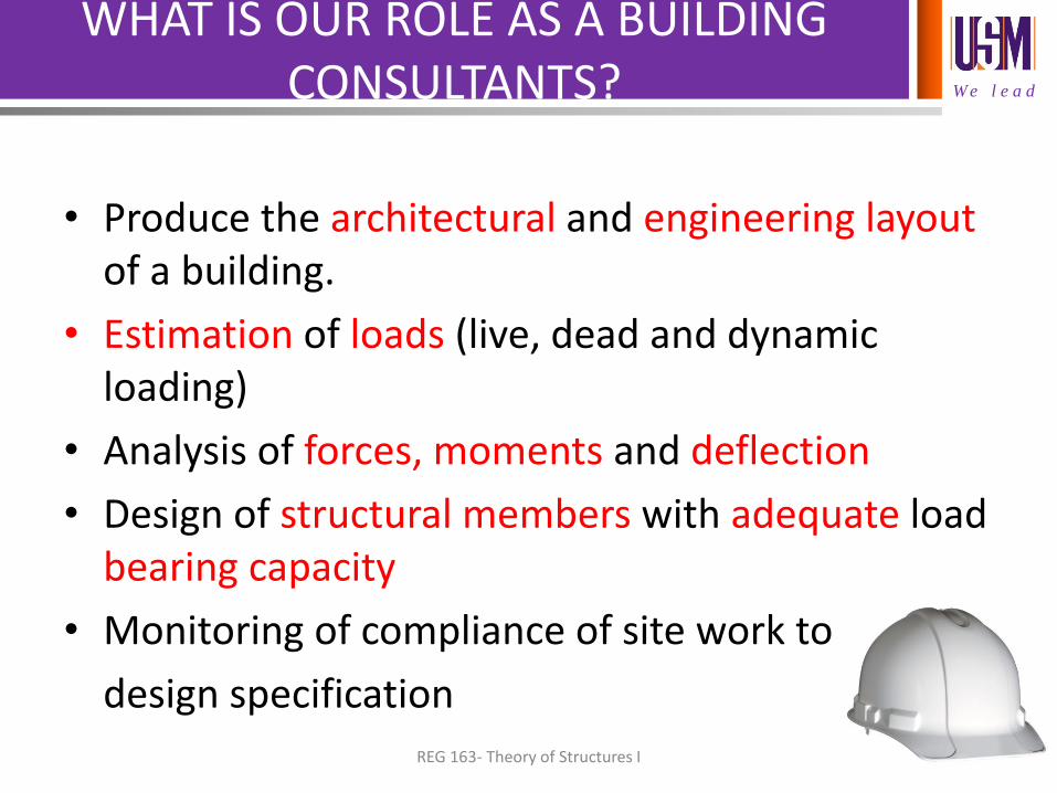
WHAT IS OUR ROLE AS A BUILDING CONSULTANTS?
• Produce the architectural and engineering layout of a building.
• Estimation of loads (live, dead and dynamic loading)
• Analysis of forces, moments and deflection
• Design of structural members with adequate load bearing capacity
• Monitoring of compliance of site work to
design specification
REG 163- Theory of Structures I
W e l e a d
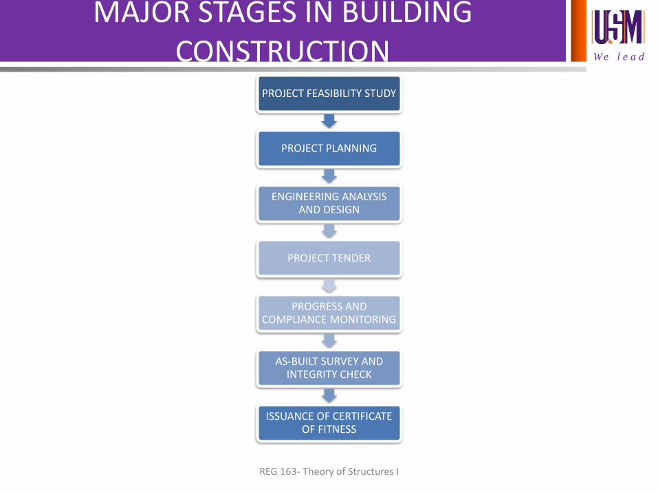
MAJOR STAGES IN BUILDING CONSTRUCTION
PROJECT FEASIBILITY STUDY
PROJECT PLANNING
ENGINEERING ANALYSIS AND DESIGN
PROJECT TENDER
PROGRESS AND COMPLIANCE MONITORING
AS-BUILT SURVEY AND INTEGRITY CHECK
ISSUANCE OF CERTIFICATE OF FITNESS
REG 163- Theory of Structures I
W e l e a d
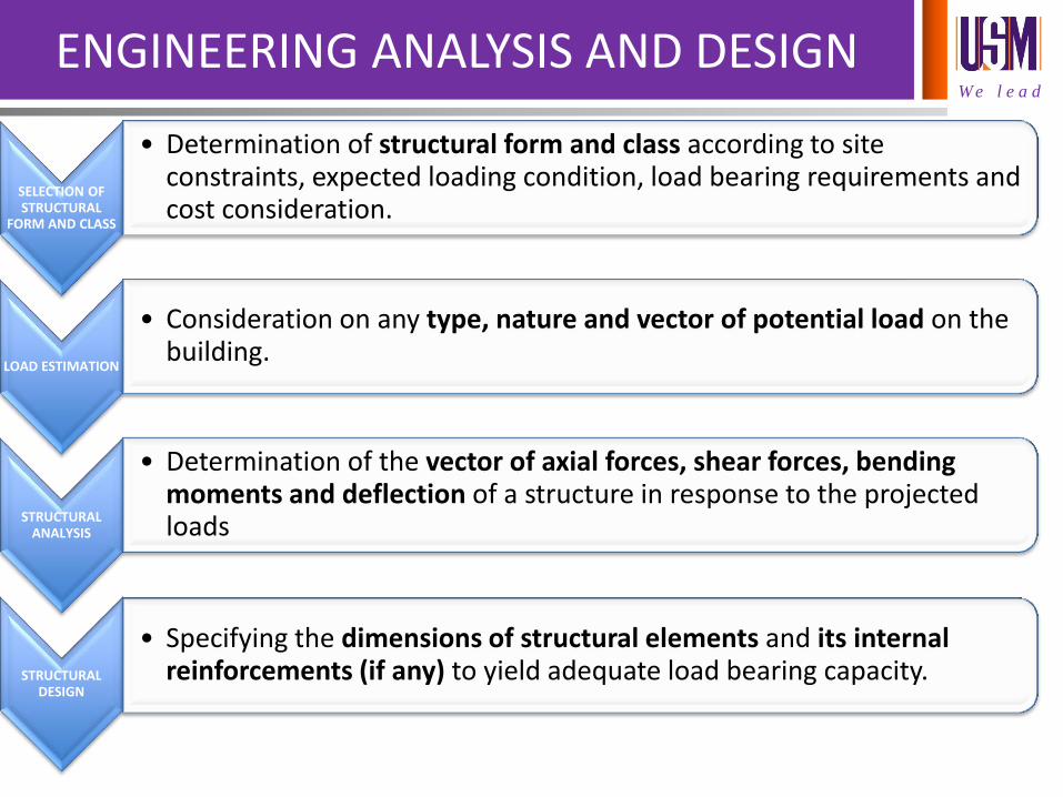
ENGINEERING ANALYSIS AND DESIGN
SELECTION OF STRUCTURAL
FORM AND CLASS
• Determination of structural form and class according to site constraints, expected loading condition, load bearing requirements and cost consideration.
LOAD ESTIMATION
• Consideration on any type, nature and vector of potential load on the building.
STRUCTURAL ANALYSIS
• Determination of the vector of axial forces, shear forces, bending moments and deflection of a structure in response to the projected loads
STRUCTURAL DESIGN
• Specifying the dimensions of structural elements and its internal reinforcements (if any) to yield adequate load bearing capacity.
W e l e a d
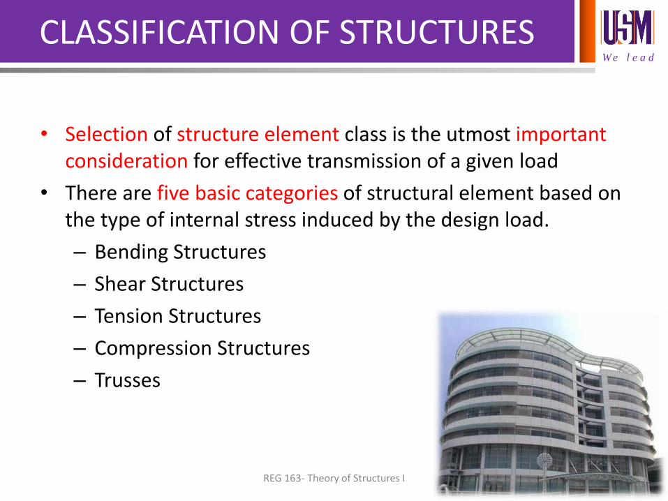
CLASSIFICATION OF STRUCTURES
• Selection of structure element class is the utmost important consideration for effective transmission of a given load
• There are five basic categories of structural element based on the type of internal stress induced by the design load.
– Bending Structures
– Shear Structures
– Tension Structures
– Compression Structures
– Trusses
REG 163- Theory of Structures I
W e l e a d
CLASSIFICATION OF STRUCTURES
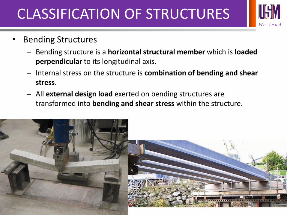
• Bending Structures – Bending structure is a horizontal structural member which is loaded
perpendicular to its longitudinal axis.
– Internal stress on the structure is combination of bending and shear stress.
– All external design load exerted on bending structures are transformed into bending and shear stress within the structure.
W e l e a d
CLASSIFICATION OF STRUCTURES
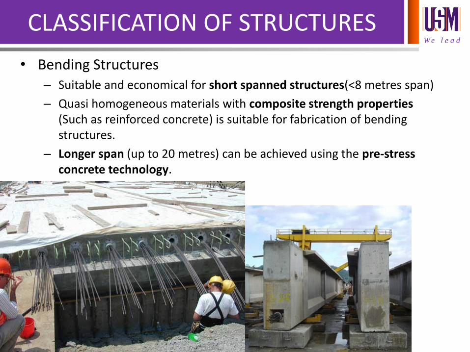
• Bending Structures – Suitable and economical for short spanned structures(<8 metres span)
– Quasi homogeneous materials with composite strength properties (Such as reinforced concrete) is suitable for fabrication of bending structures.
– Longer span (up to 20 metres) can be achieved using the pre-stress concrete technology.
W e l e a d
CLASSIFICATION OF STRUCTURES
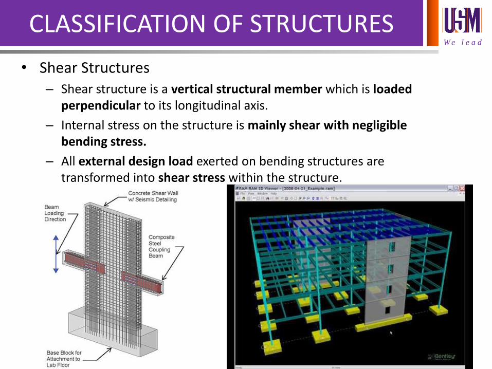
• Shear Structures – Shear structure is a vertical structural member which is loaded
perpendicular to its longitudinal axis.
– Internal stress on the structure is mainly shear with negligible bending stress.
– All external design load exerted on bending structures are transformed into shear stress within the structure.
W e l e a d
CLASSIFICATION OF STRUCTURES
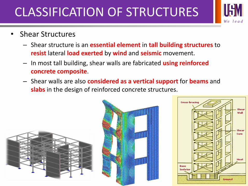
• Shear Structures – Shear structure is an essential element in tall building structures to
resist lateral load exerted by wind and seismic movement.
– In most tall building, shear walls are fabricated using reinforced concrete composite.
– Shear walls are also considered as a vertical support for beams and slabs in the design of reinforced concrete structures.
W e l e a d
CLASSIFICATION OF STRUCTURES
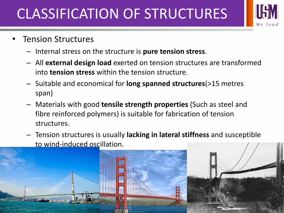
• Tension Structures – Internal stress on the structure is pure tension stress.
– All external design load exerted on tension structures are transformed into tension stress within the tension structure.
– Suitable and economical for long spanned structures(>15 metres span)
– Materials with good tensile strength properties (Such as steel and fibre reinforced polymers) is suitable for fabrication of tension structures.
– Tension structures is usually lacking in lateral stiffness and susceptible to wind-induced oscillation.
W e l e a d
CLASSIFICATION OF STRUCTURES
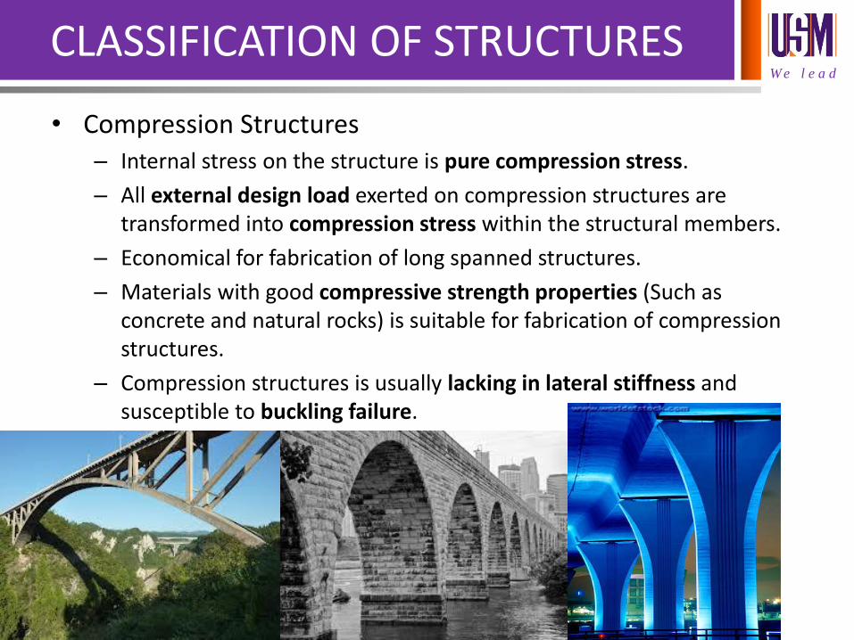
• Compression Structures – Internal stress on the structure is pure compression stress.
– All external design load exerted on compression structures are transformed into compression stress within the structural members.
– Economical for fabrication of long spanned structures.
– Materials with good compressive strength properties (Such as concrete and natural rocks) is suitable for fabrication of compression structures.
– Compression structures is usually lacking in lateral stiffness and susceptible to buckling failure.
W e l e a d
CLASSIFICATION OF STRUCTURES
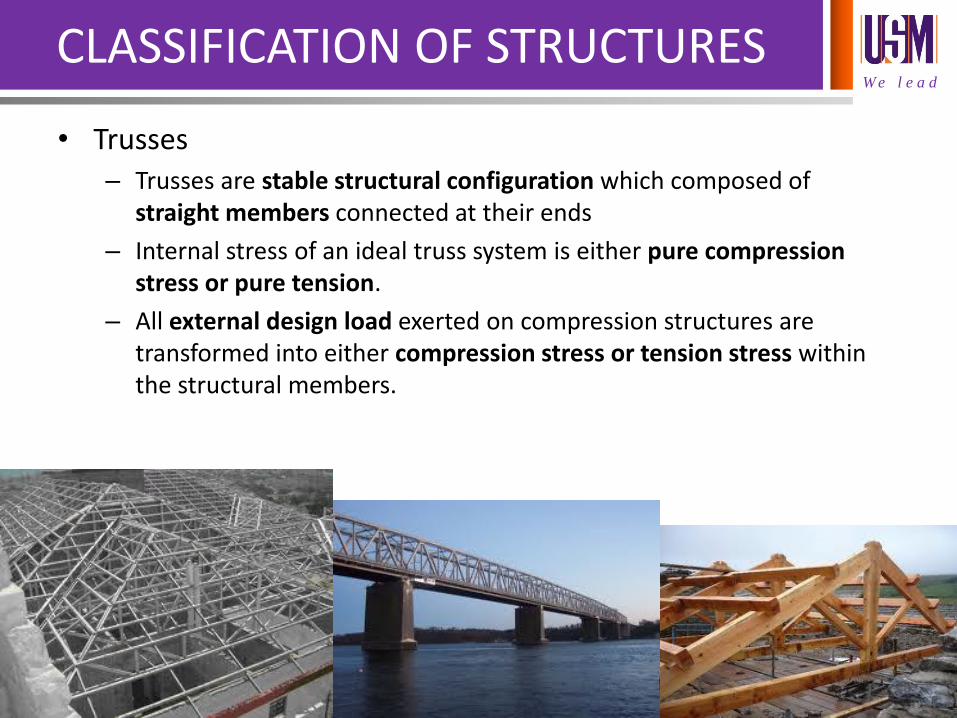
• Trusses – Trusses are stable structural configuration which composed of
straight members connected at their ends
– Internal stress of an ideal truss system is either pure compression stress or pure tension.
– All external design load exerted on compression structures are transformed into either compression stress or tension stress within the structural members.
W e l e a d
CLASSIFICATION OF STRUCTURES
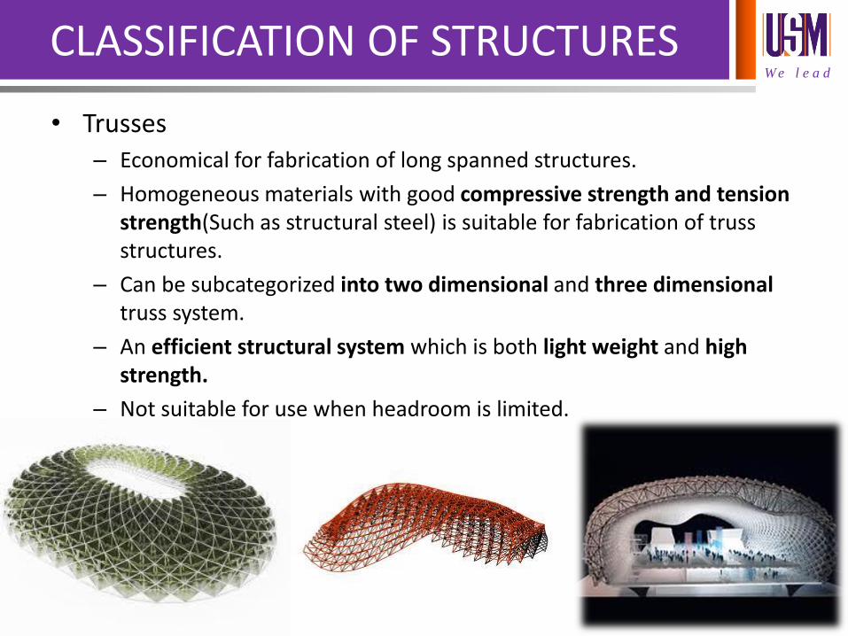
• Trusses – Economical for fabrication of long spanned structures.
– Homogeneous materials with good compressive strength and tension strength(Such as structural steel) is suitable for fabrication of truss structures.
– Can be subcategorized into two dimensional and three dimensional truss system.
– An efficient structural system which is both light weight and high strength.
– Not suitable for use when headroom is limited.

W e l e a d
PROJECT BRIEF
• TOTAL GROUP:25
• NUMBER OF STUDENTS PER GROUP:7-8
• NOTE: GROUP LIST CAN BE REFERRED IN THE ELEARN @ USM (elearning.usm.my) Portal
REG 163- Theory of Structures I
W e l e a d
PROJECT BRIEF
• PART 1: ASSESSMENT ON BENDING STRUCTURES 1.1 SUPPORT REACTION ASSESSMENT
1.2 SHEAR FORCE ASSESSMENT
1.3 BENDING MOMENT ASSESSMENT
• LABORATORY TECHNICIAN-IN-CHARGE:
PN DIANA ISME ISHAK
• GROUP COORDINATORS NEED TO BOOK THE LAB SCHEDULE WITH PN DIANA IMMEDIATELY AFTER TODAY CLASS.
• LAB ASSESSMENT WILL COMMENCE ON THE SECOND WEEK OF THE ACADEMIC SEMESTER
• THREE GROUP PER LAB SESSION
W e l e a d
PROJECT BRIEF
• PART 2: ASSESSMENT ON THE MECHANICAL PERFORMANCE OF STEEL REINFORCEMENT
2.1 PREPARATION OF STEEL REBAR AND PHYSICAL PROPERTIES ASSESSMENT
2.2 TENSILE AND YIELD STRENGTH PERFORMANCE
2.3 ASSESSMENT ON YOUNG’S MODULUS
• LABORATORY TECHNICIAN-IN-CHARGE:
PN. DIANA ISME ISHAK
• GROUP COORDINATORS NEED TO BOOK THE LAB SCHEDULE WITH THE TUTOR
• LAB WORK WILL COMMENCE ON THE SECOND WEEK OF THE ACADEMIC SEMESTER
• TWO GROUP PER LAB SESSION
W e l e a d
PROJECT REPORTING FORMAT
• TITLE PAGE (REFER TO STANDARD TEMPLATE IN E-LEARN)
• ACKNOWLEDGEMENT
• TABLE OF CONTENT
• CHAPTER 1:STRUCTURAL ASSESSMENT
• CHAPTER 2:PROPERTIES OF STEEL REINFORCEMENT
• CHAPTER 3:CONCLUSIONS
REG 163- Theory of Structures I
W e l e a d
REPORT SUBMISSION
• REPORT SHALL BE SUBMITTED INDIVIDUALLY
• SUBMISSION DATELINE:10TH MAY 2016
• CHANNEL OF SUBMISSION: E-LEARN SYSTEM
• DOCUMENT SHALL BE IN MS WORD FORMAT(doc. File)
• File name nomenclature order:
Group No._Student Name_Matric Number
• Severe action will be taken in the event of plagiarism
REG 163- Theory of Structures I
W e l e a d
ANALYSIS OF PLANE TRUSSES
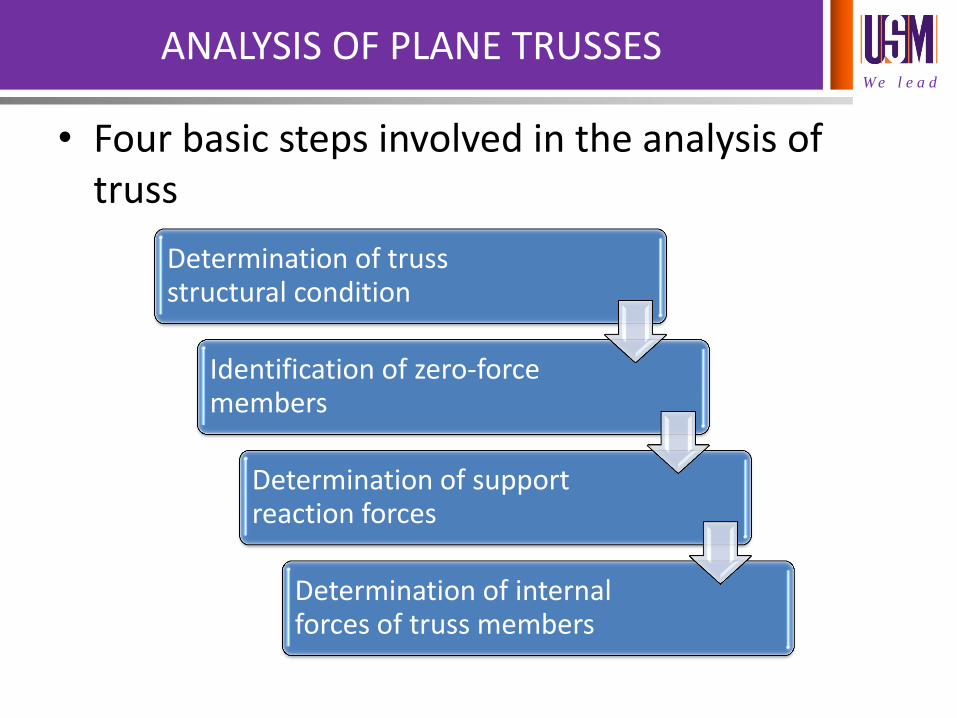
• Four basic steps involved in the analysis of truss
Determination of truss structural condition
Identification of zero-force members
Determination of support reaction forces
Determination of internal forces of truss members
W e l e a d
ANALYSIS OF PLANE TRUSSES-STEP 1
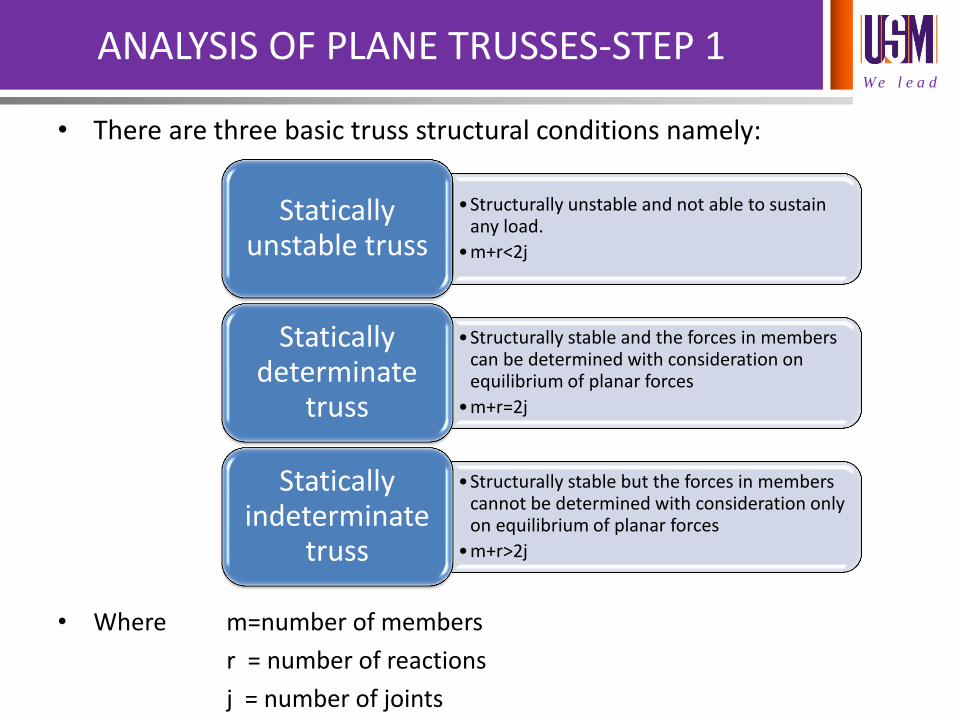
• There are three basic truss structural conditions namely:
• Where m=number of members
r = number of reactions
j = number of joints
•Structurally unstable and not able to sustain any load.
•m+r<2j
Statically unstable truss
•Structurally stable and the forces in members can be determined with consideration on equilibrium of planar forces
•m+r=2j
Statically determinate
truss
•Structurally stable but the forces in members cannot be determined with consideration only on equilibrium of planar forces
•m+r>2j
Statically indeterminate
truss
W e l e a d
ANALYSIS OF PLANE TRUSSES
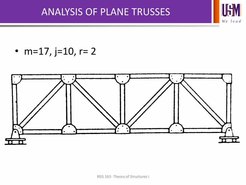
• m=17, j=10, r= 2
REG 163- Theory of Structures I
W e l e a d
ANALYSIS OF PLANE TRUSSES
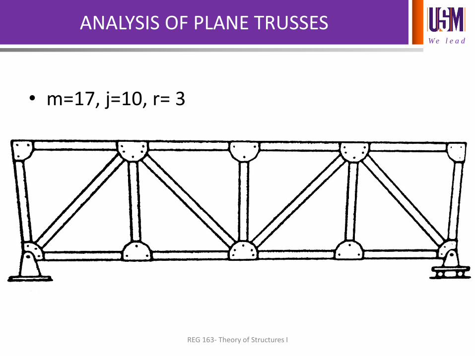
• m=17, j=10, r= 3
REG 163- Theory of Structures I
W e l e a d
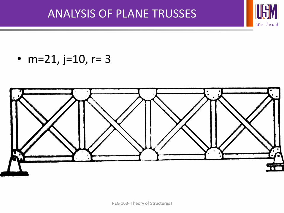
ANALYSIS OF PLANE TRUSSES
• m=21, j=10, r= 3
REG 163- Theory of Structures I
W e l e a d
ANALYSIS OF PLANE TRUSSES-STEP 2
• Identification of zero force members:
– Performed to expedite the analysis of forces of members in a truss system.
– There is only two conditions that a member of truss will have zero force.
REG 163- Theory of Structures I
W e l e a d
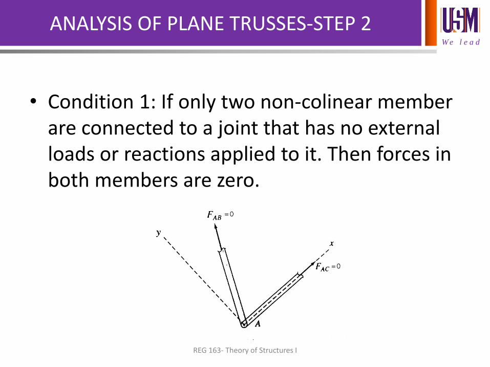
ANALYSIS OF PLANE TRUSSES-STEP 2
• Condition 1: If only two non-colinear member are connected to a joint that has no external loads or reactions applied to it. Then forces in both members are zero.
REG 163- Theory of Structures I
W e l e a d
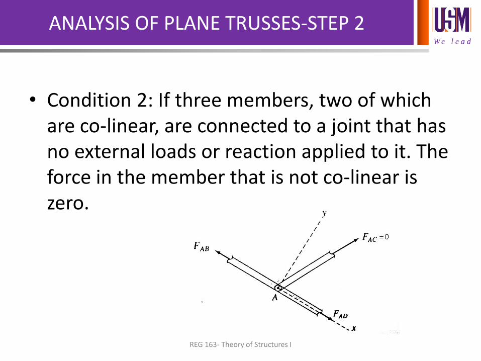
ANALYSIS OF PLANE TRUSSES-STEP 2
• Condition 2: If three members, two of which are co-linear, are connected to a joint that has no external loads or reaction applied to it. The force in the member that is not co-linear is zero.
REG 163- Theory of Structures I
W e l e a d
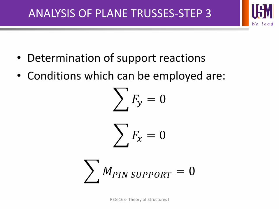
ANALYSIS OF PLANE TRUSSES-STEP 3
• Determination of support reactions
• Conditions which can be employed are:
𝐹𝑦 = 0
𝐹𝑥 = 0
𝑀𝑃𝐼𝑁 𝑆𝑈𝑃𝑃𝑂𝑅𝑇 = 0
REG 163- Theory of Structures I
W e l e a d
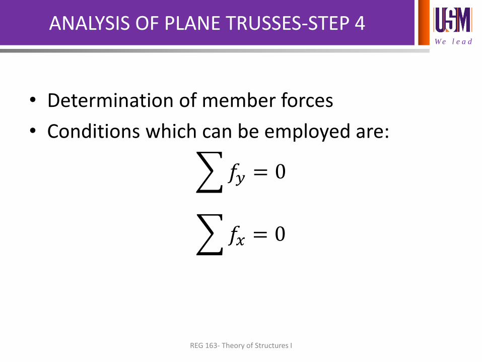
ANALYSIS OF PLANE TRUSSES-STEP 4
• Determination of member forces
• Conditions which can be employed are:
𝑓𝑦 = 0
𝑓𝑥 = 0
REG 163- Theory of Structures I
W e l e a d
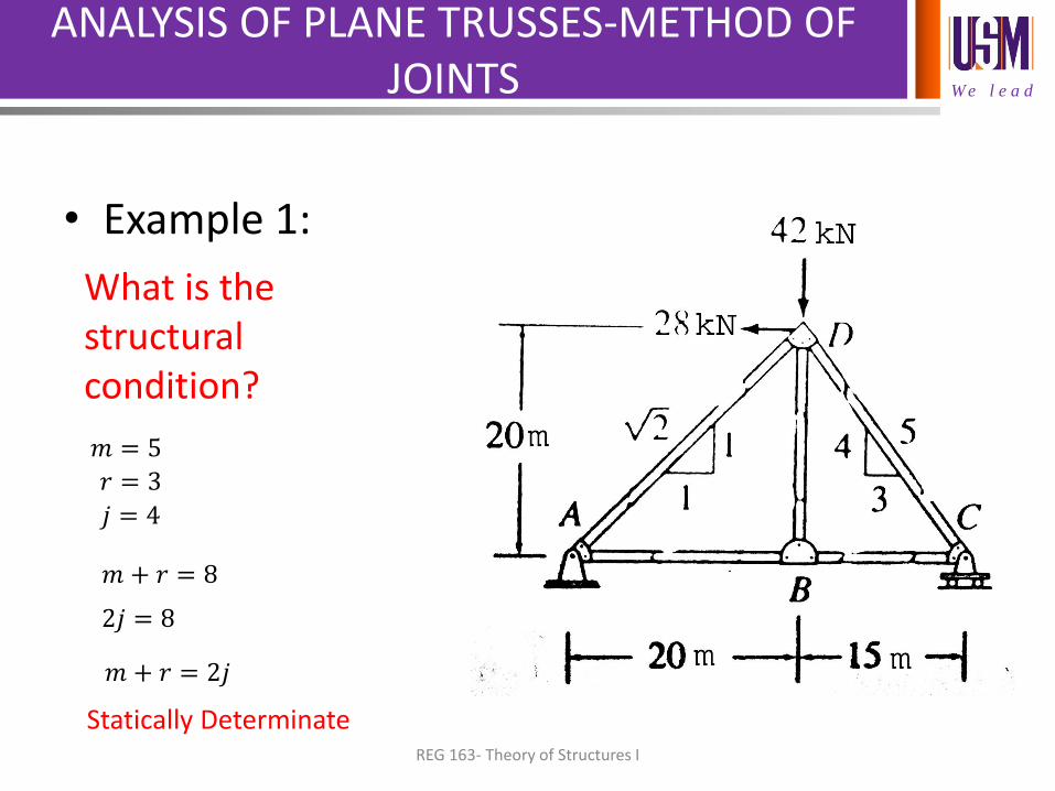
ANALYSIS OF PLANE TRUSSES-METHOD OF JOINTS
• Example 1:
What is the structural condition?
REG 163- Theory of Structures I
𝑚 = 5
𝑟 = 3
𝑗 = 4
𝑚 + 𝑟 = 8
2𝑗 = 8
𝑚 + 𝑟 = 2𝑗
Statically Determinate
W e l e a d
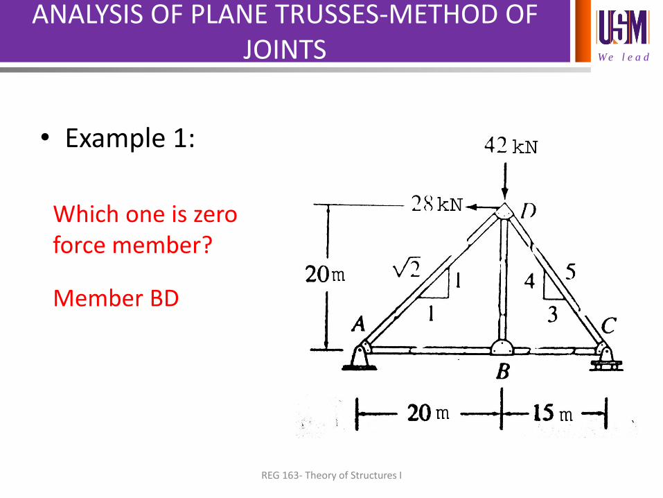
ANALYSIS OF PLANE TRUSSES-METHOD OF JOINTS
• Example 1:
Which one is zero force member?
Member BD
REG 163- Theory of Structures I
W e l e a d
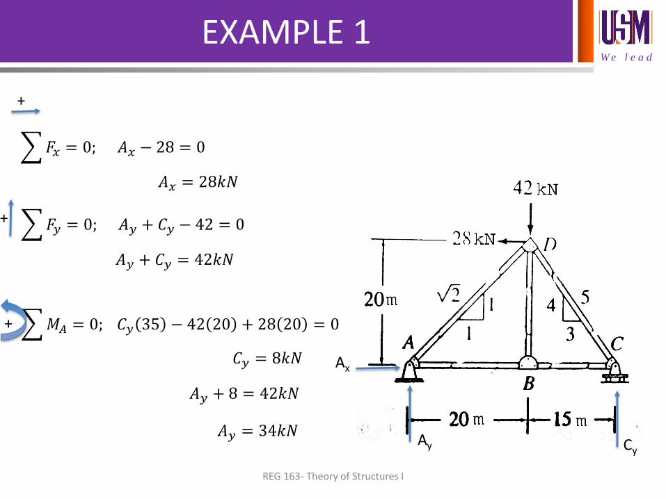
EXAMPLE 1
Ax
Ay Cy
𝐹𝑥 = 0; 𝐴𝑥 − 28 = 0
𝐴𝑥 = 28𝑘𝑁
+
𝐹𝑦 = 0; 𝐴𝑦 + 𝐶𝑦 − 42 = 0
𝐴𝑦 + 𝐶𝑦 = 42𝑘𝑁
+
𝑀𝐴 = 0; 𝐶𝑦 35 − 42 20 + 28 20 = 0 +
𝐶𝑦 = 8𝑘𝑁
𝐴𝑦 + 8 = 42𝑘𝑁
𝐴𝑦 = 34𝑘𝑁
REG 163- Theory of Structures I
W e l e a d
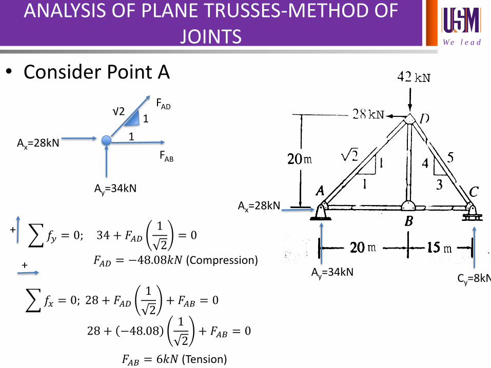
ANALYSIS OF PLANE TRUSSES-METHOD OF JOINTS
• Consider Point A
Ax=28kN
Ay=34kN Cy=8kN
Ax=28kN
1
1
√2
Ay=34kN
FAD
FAB
𝑓𝑦 = 0; 34 + 𝐹𝐴𝐷1
2= 0
𝐹𝐴𝐷 = −48.08𝑘𝑁 (Compression)
+
𝑓𝑥 = 0; 28 + 𝐹𝐴𝐷1
2+ 𝐹𝐴𝐵 = 0
𝐹𝐴𝐵 = 6𝑘𝑁 (Tension)
+
28 + −48.081
2+ 𝐹𝐴𝐵 = 0
W e l e a d
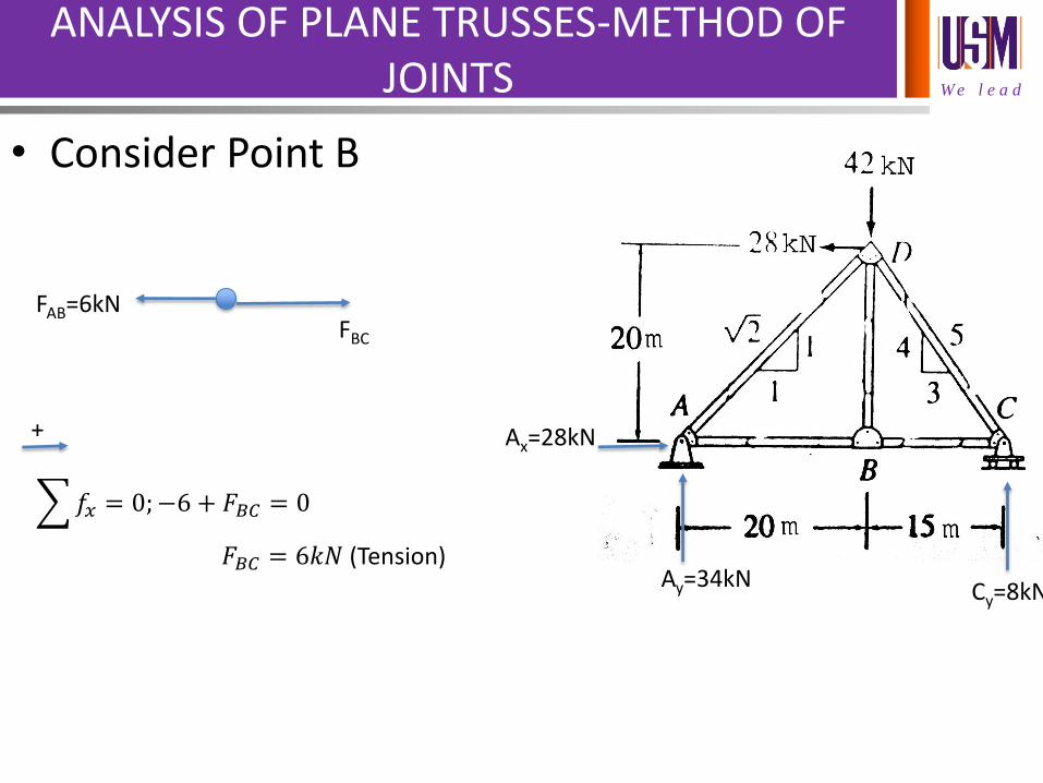
ANALYSIS OF PLANE TRUSSES-METHOD OF JOINTS
• Consider Point B
Ax=28kN
Ay=34kN Cy=8kN
FAB=6kN FBC
𝑓𝑥 = 0;−6 + 𝐹𝐵𝐶 = 0
𝐹𝐵𝐶 = 6𝑘𝑁 (Tension)
+
W e l e a d
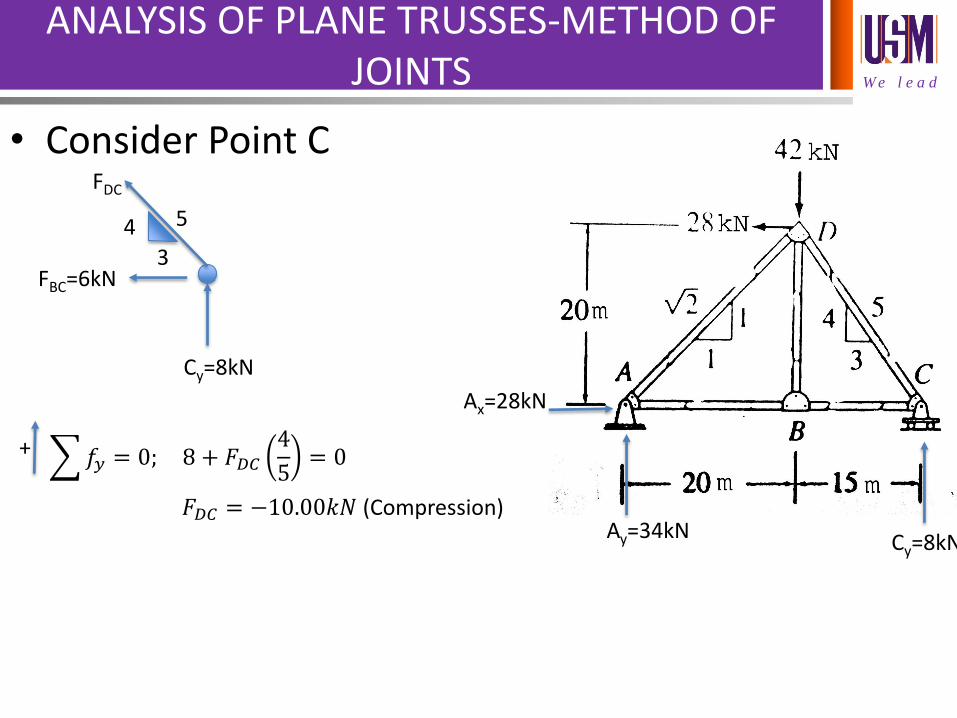
ANALYSIS OF PLANE TRUSSES-METHOD OF JOINTS
• Consider Point C
Ax=28kN
Ay=34kN Cy=8kN
FBC=6kN
4
3
5
Cy=8kN
FDC
𝑓𝑦 = 0; 8 + 𝐹𝐷𝐶4
5= 0
𝐹𝐷𝐶 = −10.00𝑘𝑁 (Compression)
+
W e l e a d
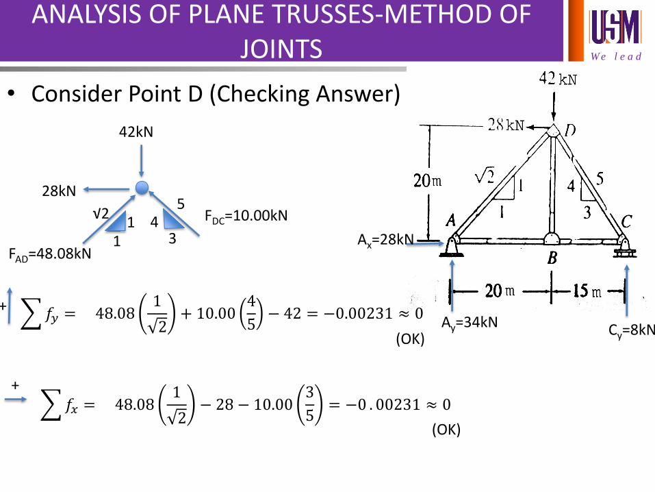
ANALYSIS OF PLANE TRUSSES-METHOD OF JOINTS
• Consider Point D (Checking Answer)
Ax=28kN
Ay=34kN Cy=8kN
28kN
1 1
√2
3 4
5
FAD=48.08kN
FDC=10.00kN
42kN
𝑓𝑦 = 48.081
2+ 10.00
4
5− 42 = −0.00231 ≈ 0
(OK)
+
𝑓𝑥 = 48.081
2− 28 − 10.00
3
5= −0 . 00231 ≈ 0
(OK)
+
W e l e a d
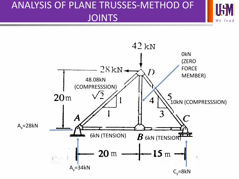
ANALYSIS OF PLANE TRUSSES-METHOD OF JOINTS
Ax=28kN
Ay=34kN Cy=8kN
0kN (ZERO FORCE MEMBER)
10kN (COMPRESSSION)
6kN (TENSION) 6kN (TENSION)
48.08kN (COMPRESSSION)
W e l e a d
TEST
• DATE:8 MARCH 2016
• DURATION: 1.5 HOURS
• SCOPE:
STRUCTURE CLASSES
TRUSS ANALYSIS
STRUCTURE FORM
REG 163- Theory of Structures I
W e l e a d
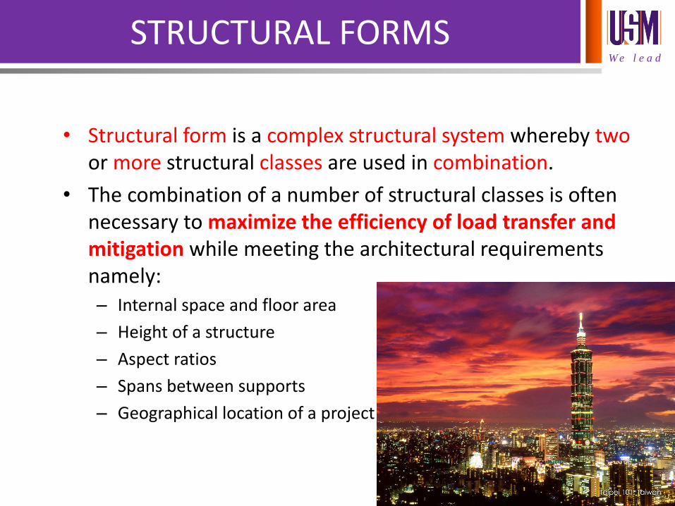
STRUCTURAL FORMS
• Structural form is a complex structural system whereby two or more structural classes are used in combination.
• The combination of a number of structural classes is often necessary to maximize the efficiency of load transfer and mitigation while meeting the architectural requirements namely: – Internal space and floor area
– Height of a structure
– Aspect ratios
– Spans between supports
– Geographical location of a project
W e l e a d
STRUCTURAL FORMS
• The five main structural form of building which can be found locally are as follows:
– Braced frame structure
– Rigid frame structure
– In-filled frame structure
– Shear walls structure
– Wall-frame structure
W e l e a d
BRACED FRAME STRUCTURE
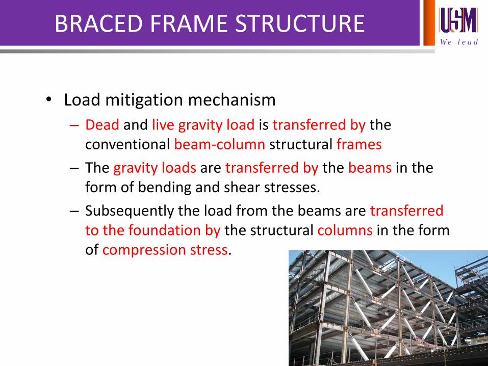
• Load mitigation mechanism
– Dead and live gravity load is transferred by the conventional beam-column structural frames
– The gravity loads are transferred by the beams in the form of bending and shear stresses.
– Subsequently the load from the beams are transferred to the foundation by the structural columns in the form of compression stress.
W e l e a d
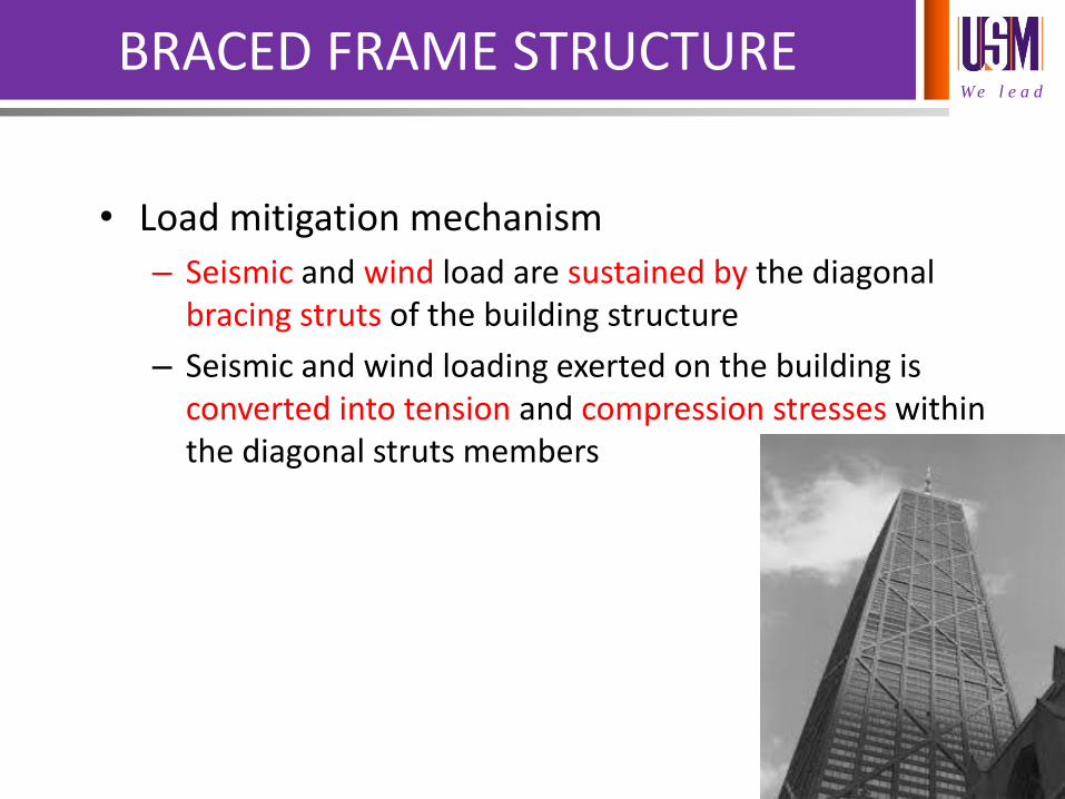
BRACED FRAME STRUCTURE
• Load mitigation mechanism
– Seismic and wind load are sustained by the diagonal bracing struts of the building structure
– Seismic and wind loading exerted on the building is converted into tension and compression stresses within the diagonal struts members
W e l e a d
BRACED FRAME STRUCTURE
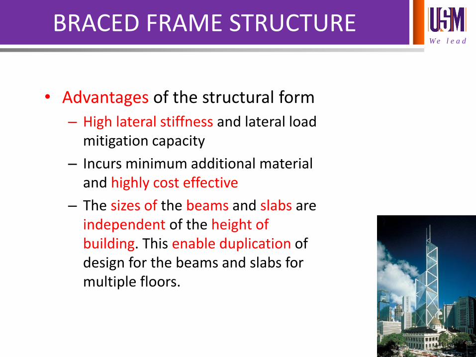
• Advantages of the structural form
– High lateral stiffness and lateral load mitigation capacity
– Incurs minimum additional material and highly cost effective
– The sizes of the beams and slabs are independent of the height of building. This enable duplication of design for the beams and slabs for multiple floors.
W e l e a d
BRACED FRAME STRUCTURE
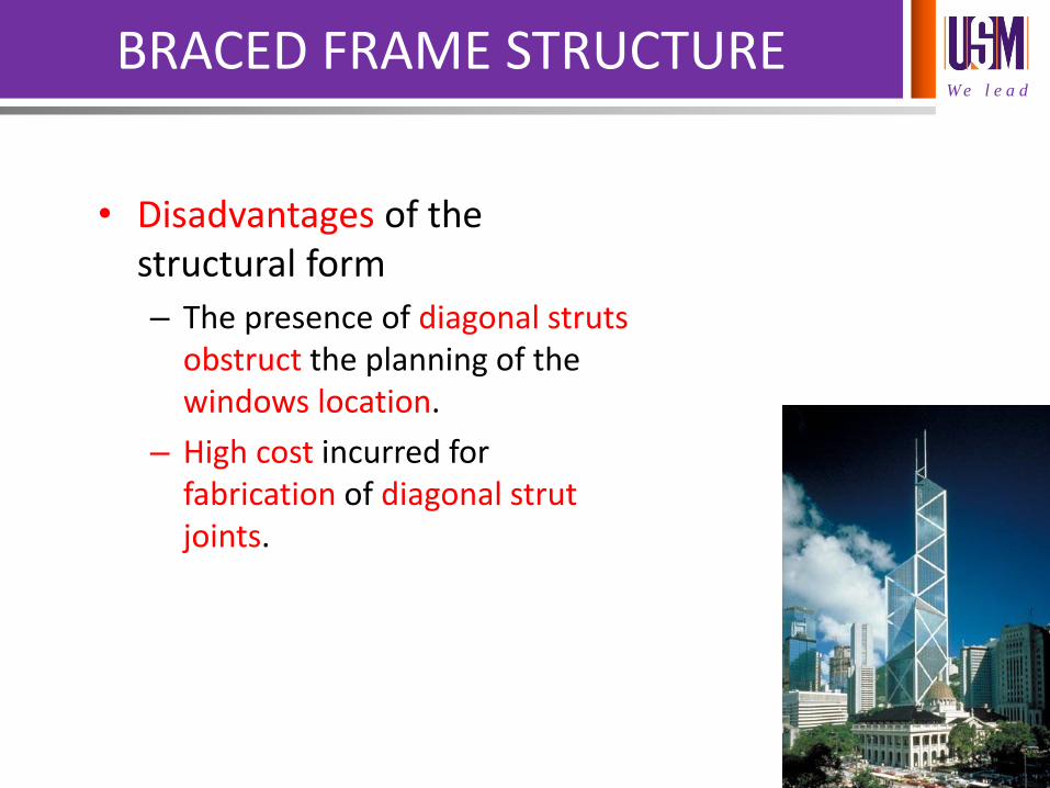
• Disadvantages of the structural form
– The presence of diagonal struts obstruct the planning of the windows location.
– High cost incurred for fabrication of diagonal strut joints.
W e l e a d
RIGID FRAME STRUCTURE
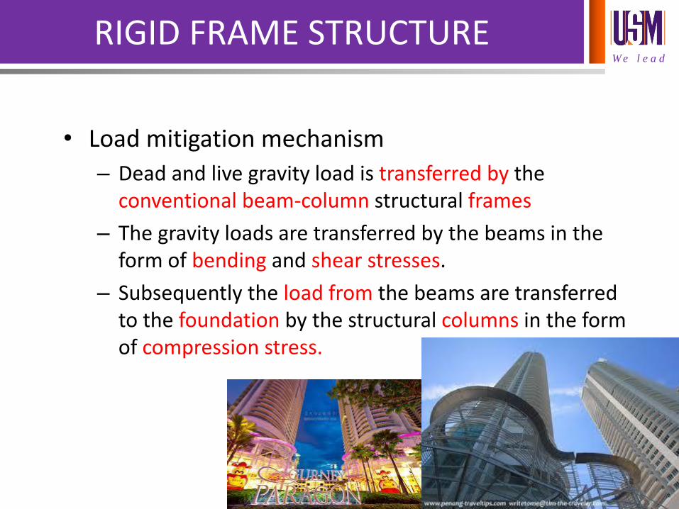
• Load mitigation mechanism
– Dead and live gravity load is transferred by the conventional beam-column structural frames
– The gravity loads are transferred by the beams in the form of bending and shear stresses.
– Subsequently the load from the beams are transferred to the foundation by the structural columns in the form of compression stress.
W e l e a d
RIGID FRAME STRUCTURE
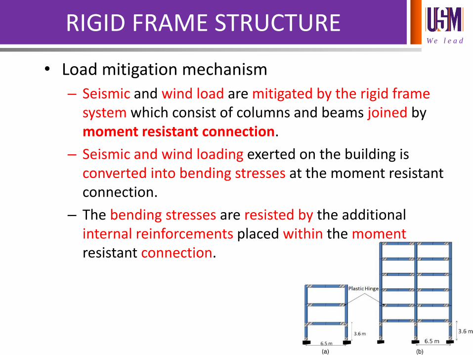
• Load mitigation mechanism
– Seismic and wind load are mitigated by the rigid frame system which consist of columns and beams joined by moment resistant connection.
– Seismic and wind loading exerted on the building is converted into bending stresses at the moment resistant connection.
– The bending stresses are resisted by the additional internal reinforcements placed within the moment resistant connection.
W e l e a d
RIGID FRAME STRUCTURE
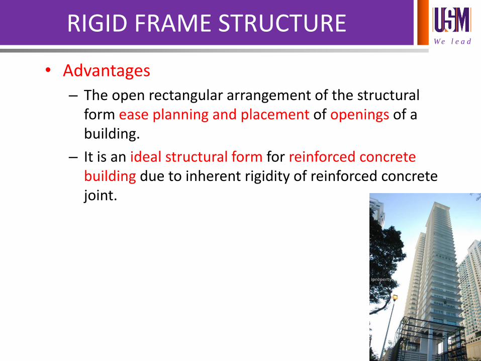
• Advantages
– The open rectangular arrangement of the structural form ease planning and placement of openings of a building.
– It is an ideal structural form for reinforced concrete building due to inherent rigidity of reinforced concrete joint.
W e l e a d
RIGID FRAME STRUCTURE
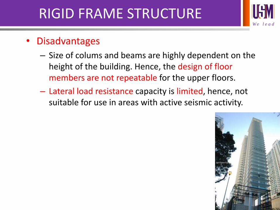
• Disadvantages
– Size of colums and beams are highly dependent on the height of the building. Hence, the design of floor members are not repeatable for the upper floors.
– Lateral load resistance capacity is limited, hence, not suitable for use in areas with active seismic activity.
W e l e a d
INFILLED FRAME STRUCTURE
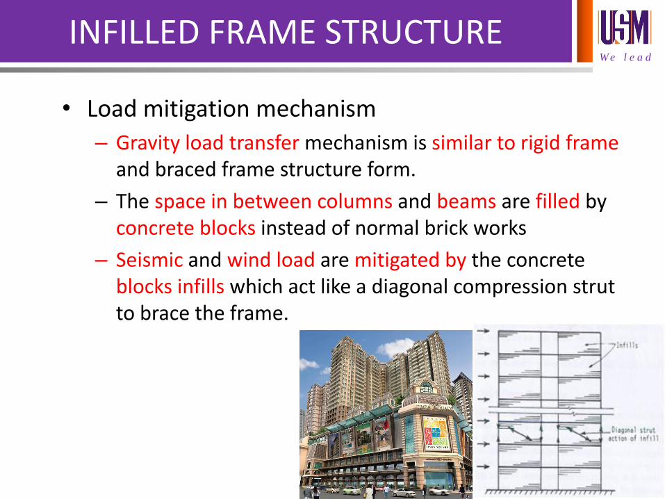
• Load mitigation mechanism
– Gravity load transfer mechanism is similar to rigid frame and braced frame structure form.
– The space in between columns and beams are filled by concrete blocks instead of normal brick works
– Seismic and wind load are mitigated by the concrete blocks infills which act like a diagonal compression strut to brace the frame.
W e l e a d
INFILLED FRAME STRUCTURE
• Advantages
– Infills which normally serves as external or internal walls serves additional function of increasing lateral stiffness to resist lateral loads
• Disadvantages
– Unpredictable infill strength due to complex interaction behavior of infill and frame.
– Higher cost for placement of concrete blocks instead of conventional bricks.
W e l e a d
SHEAR WALL STRUCTURE
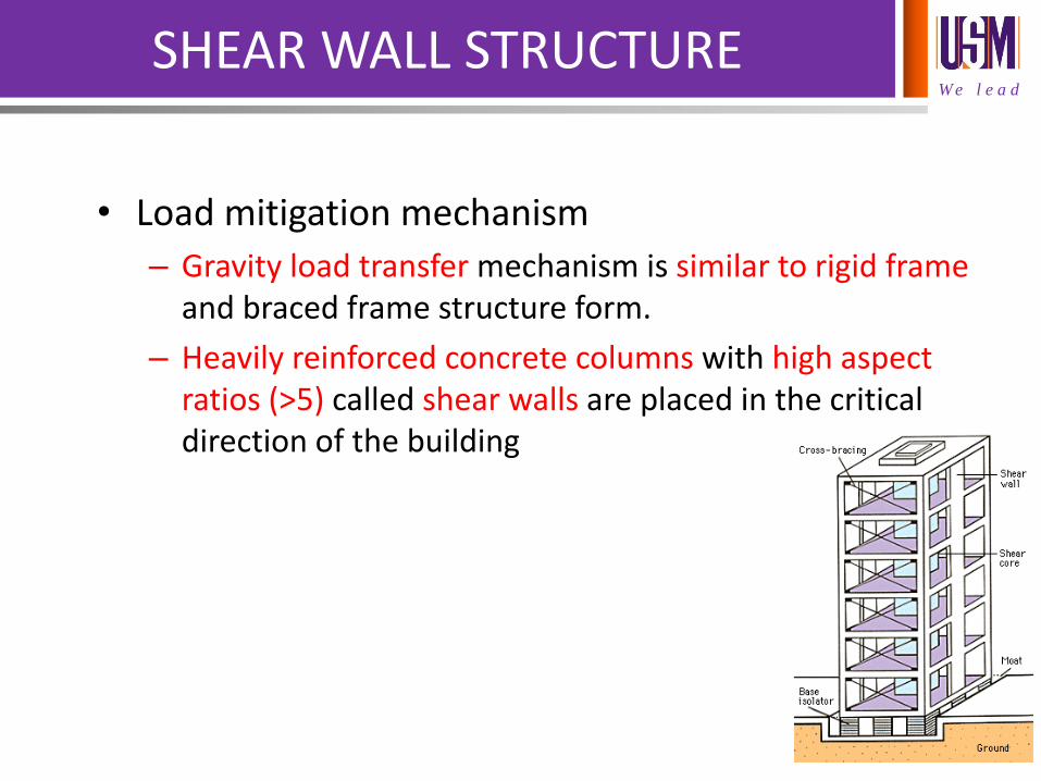
• Load mitigation mechanism
– Gravity load transfer mechanism is similar to rigid frame and braced frame structure form.
– Heavily reinforced concrete columns with high aspect ratios (>5) called shear walls are placed in the critical direction of the building
W e l e a d
SHEAR WALL STRUCTURE
• Load mitigation mechanism
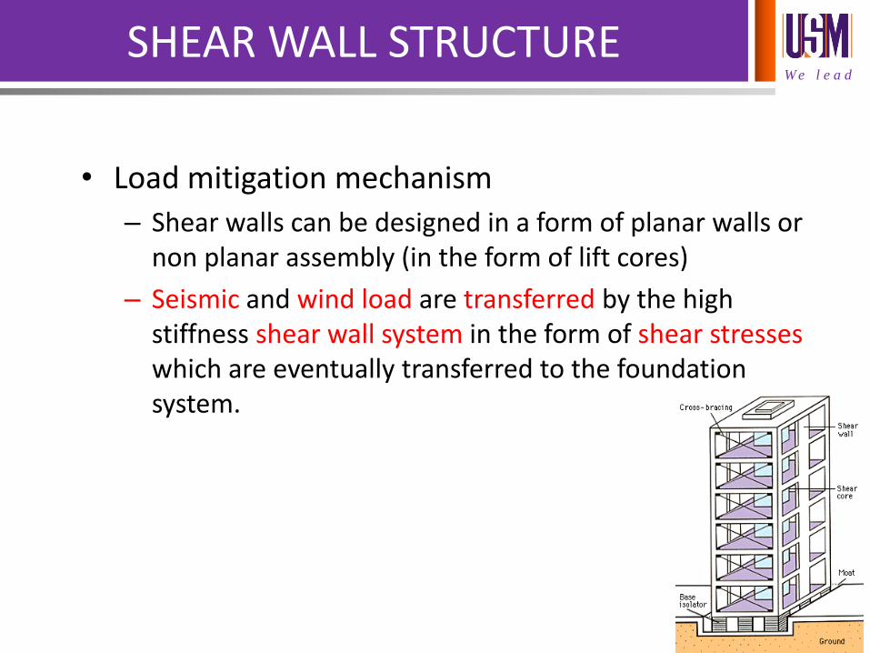
– Shear walls can be designed in a form of planar walls or non planar assembly (in the form of lift cores)
– Seismic and wind load are transferred by the high stiffness shear wall system in the form of shear stresses which are eventually transferred to the foundation system.
W e l e a d
SHEAR WALL STRUCTURE
• Advantages
– Higher lateral stiffness and lateral load resistance as compared to infilled frame and rigid frame structures
– Exceptional seismic load resisting performance.
• Disadvantages
– The presence of large numbers of shear walls impose restriction on the planning of the internal spaces of a building.
W e l e a d
WALL-FRAME STRUCTURE
• Load mitigation mechanism
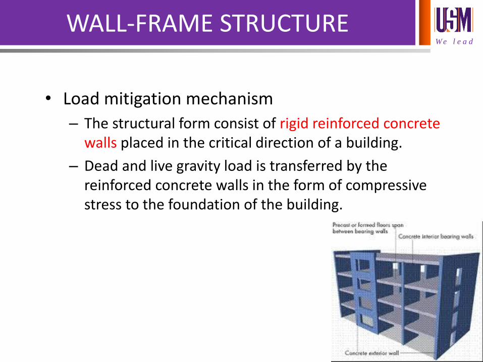
– The structural form consist of rigid reinforced concrete walls placed in the critical direction of a building.
– Dead and live gravity load is transferred by the reinforced concrete walls in the form of compressive stress to the foundation of the building.
W e l e a d
WALL-FRAME STRUCTURE
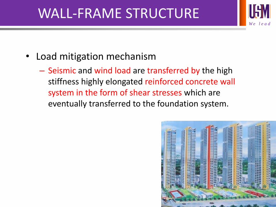
• Load mitigation mechanism
– Seismic and wind load are transferred by the high stiffness highly elongated reinforced concrete wall system in the form of shear stresses which are eventually transferred to the foundation system.
W e l e a d
WALL-FRAME STRUCTURE
• Advantages
– Very high lateral stiffness and lateral load resistance.
– The dimension of walls and floors are highly uniform. This allows the use of system form work which greatly expedite the construction progress.
• Disadvantages
– The presence of large numbers of elongated reinforced concrete walls impose heavy restriction on the planning of the internal spaces of a building.

Presented by
DR CHEAH CHEE BAN | SENIOR LECTURER, SCHOOL OF HOUSING, BUILDING AND PLANNING