Embed Size (px)
Citation preview

Applying Laser Physics to Electron MicroscopyAndrew and Kevin

Theory
● An optical cavity is used to trap and intensify light
● We used two supermirrors with 99.99% reflectivity

How light affects electrons
● intensified resonating light utilizes the compton effect

Ponderomotive Force
● Compton effect on the large scale

How an electron microscope works
● Zernike phase plate shifts electrons to increase phase contrast

Our Professor’s theory
● The effect the Zernike phase plate creates can be replicated by an optical cavity
● Gets rid of durability issues

Implementation: Laser Power
The necessary laser power can be calculated using the following equation:
where delta is the deflection of the electrons, gamma =1/(1-(v^2c^2)), v is the velocity of the electrons, P is the
power required, and N = 0.030(Numerical Aperature)/1-r, where r is the reflectivity of our mirrors. ???

Basically, because we want our phase shift ( ) to be pi/2, ẟwe, want the right part of the equation to be equal to 1. This means that, after plugging in numbers, we wanted to make an optical cavity where we maximized our numerical aperture and finesse on our cavity. Numerical aperture can be thought of as the range at which an optical tool can accept light, and finesse can be thought of as how effective the cavity is at trapping light. So we want a cavity that accepts light over a wide range and has high reflectivity

Approach 1: Parabolic Cavity
The first way that was attempted was to use a parabolic shaped optical cavity to focus light at the parabola focus.

Advantages of this were that 1. The parabolic mirror was actually easier to manufacture than the next method we will describe2. It is easier to reduce loss with this system, resulting in a greater finesse

However, a disadvantage was that a lot of light spilled over the edge of the parabola, resulting in a low Numerical Aperture (acceptance angle). In addition, a lot of efficiency was lost because the light wasn’t radially polarized.

Radially Polarizing the Light
● waveplates work because they are birefringent! (polarization affects refractive index)

Segmented Waveplate80k euros :(

Approach 2: Spherical Cavity
We get a pair of mirrors that make parts of a sphere, and place them so that they are concentric: as in the diagram below:
L
RM = 2(f)
R(L/2)

Advantages of this were a higher Numerical Aperture, while keeping a pretty high finesse.
This is the design that we worked on

This was our schematic
It looks scary but much of it was for shaping and directing the laser beam so that it suited our needs

This is what our lab table looked like
LASER SOURCECAVITY

Close-up of Cavity Setup
MIRROR 2
MIRROR 1MEASURINGEQUIPMENT
Determining Numerical AperatureWe used a camera to capture the light that left the cavityThe bright spot in the middle shows the size of the light leaving the cavity (should be same as the light entering the cavity), giving us our Numerical Aperture

Determining Finesse
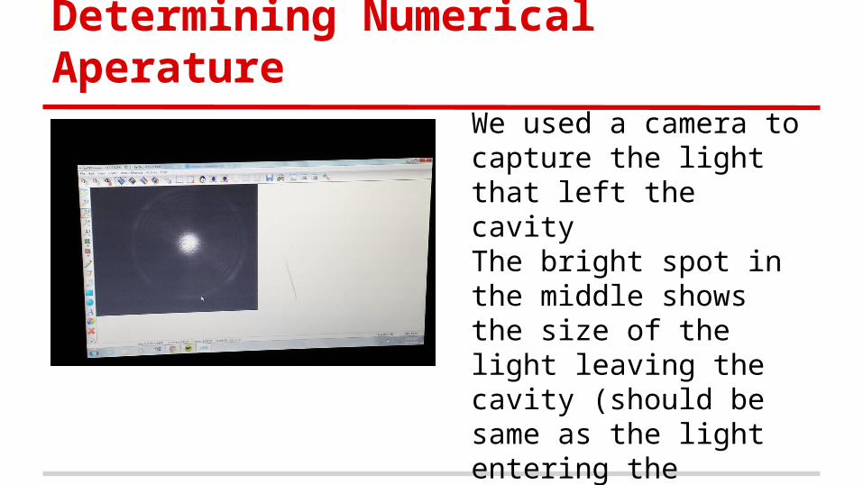
We scanned the frequency of the cavity, and plotted the light brightness vs. frequency on an oscilloscope. The brightness of the light spikes at the resonant frequency of the cavity.

The thinner and taller the spike was, the higher the finesse of our cavity turned out to be. Thus, you can see we had a fairly thin and tall spike, indicating a decently high finesse. The high NA and finesse fit our power requirements as calculated before, and so we proved that the theory of using lasers to create phase contrast is viable.

Keeping the Cavity Locked
One issue we had was that the resonance of the cavity kept drifting away due to uncontrollable factors (room temperature, shaking, frequency drift, etc). We decided to implement a negative feedback loop to correct the cavity
Pound-Drever-Hall Lock
Commonly used technique in laser optics, basically implemented a feedback loop to correct the cavity of any errors. By taking data using a photodetector, we could generate an error signal to show how much the frequency was off by, and autocorrect the laser.


![Ultrafast transmission electron microscopy using a laser ...transmission electron microscopy [4], scanning electron microscopy [5], x-ray diffraction [6], scanning tunneling and atomic](https://img.pdfslide.us/doc/110x75/607eb1335ce8082131294459/ultrafast-transmission-electron-microscopy-using-a-laser-transmission-electron.jpg)