Embed Size (px)
Citation preview

EAST WEST UNIVERSITY
DEPARTMENT OF ELECTRICAL AND ELECTRONIC ENGINEERING
LAB-REPORT
Experiment No: 05
Experiment Name : Introducing Router & Basic Router Configuration
Course code : EEE 433
Course Name: COMPUTER NETWORKS
Section: 1
SUBMITTED BY
Name: Md. Rouzatun Rafiue
ID: 2011-1-80-060
SUBMITTED TO
FMA
Date of Performance: 18-11-2014
Date of submission : 20-11-2014

Objective:
The objective of this experiment is to learn about the routers, their various features and the basic configuration command.
Fig-1: The topology diagram of the network
PC configuration :
AUST
Gateway : 192.168.1.1
DNS Server : 192.168.1.5
IP Address : 192.168.1.2
EWU
Gateway : 192.168.1.1
DNS Server : 192.168.1.5
IP Address : 192.168.1.3
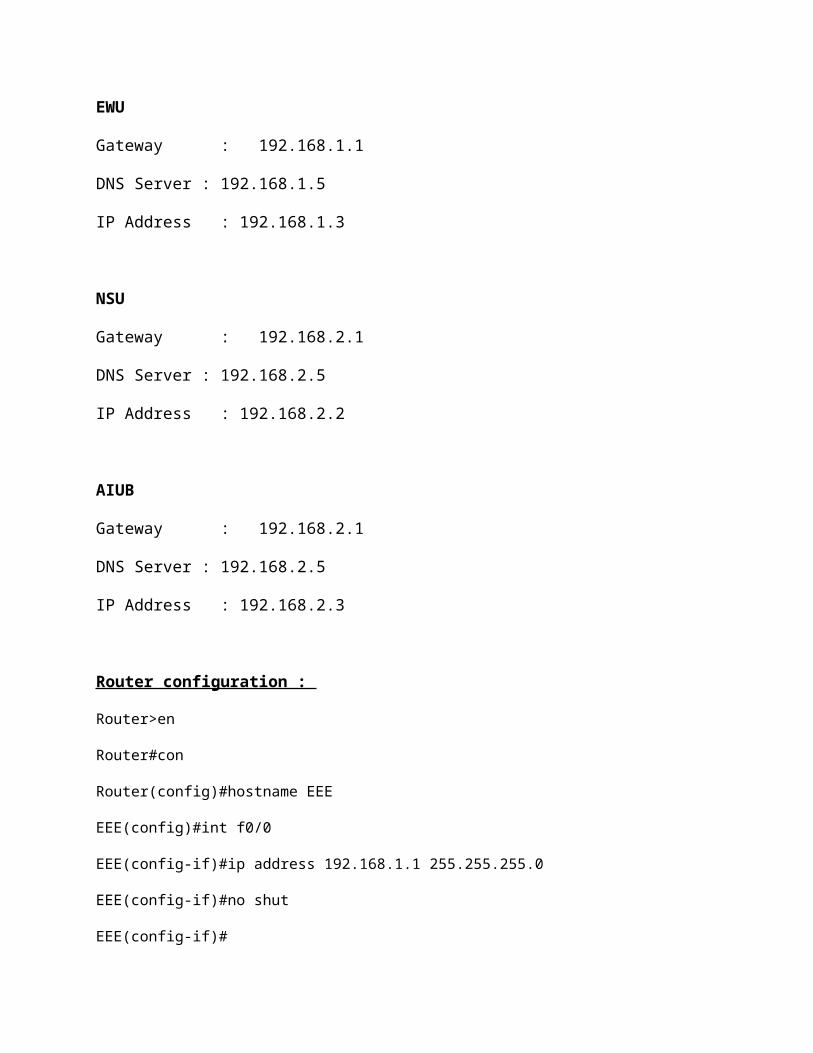
NSU
Gateway : 192.168.2.1
DNS Server : 192.168.2.5
IP Address : 192.168.2.2
AIUB
Gateway : 192.168.2.1
DNS Server : 192.168.2.5
IP Address : 192.168.2.3
Router configuration :
Router>en
Router#con
Router(config)#hostname EEE
EEE(config)#int f0/0
EEE(config-if)#ip address 192.168.1.1 255.255.255.0
EEE(config-if)#no shut
EEE(config-if)#
EEE(config-if)#exit
EEE(config)#
EEE(config)#int f1/0
EEE(config-if)#ip address 192.168.2.1 255.255.255.0
EEE(config-if)#no shut
EEE(config-if)#exit
EEE(config)#router rip

EEE(config-router)#version 2
EEE(config-router)#network 192.168.1.0
EEE(config-router)#network 192.168.2.0
EEE(config-router)#exit
EEE(config)#ip host AUST 192.168.1.2
EEE(config)#ip host EWU 192.168.1.3
EEE(config)#ip host NSU 192.168.2.2
EEE(config)#ip host AIUB 192.168.2.3
EEE(config)#exit
EEE#copy run start
EEE#sh run
EEE#sh int
FastEthernet0/0 is up, line protocol is up (connected)
Hardware is Lance, address is 0060.4785.add2 (bia 0060.4785.add2)
Internet address is 192.168.1.1/24
MTU 1500 bytes, BW 100000 Kbit, DLY 100 usec,
reliability 255/255, txload 1/255, rxload 1/255
Encapsulation ARPA, loopback not set
ARP type: ARPA, ARP Timeout 04:00:00,
Last input 00:00:08, output 00:00:05, output hang never
Last clearing of "show interface" counters never
Input queue: 0/75/0 (size/max/drops); Total output drops: 0
Queueing strategy: fifo
Output queue :0/40 (size/max)
5 minute input rate 0 bits/sec, 0 packets/sec
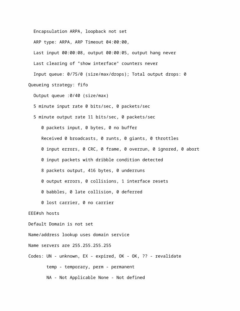
5 minute output rate 11 bits/sec, 0 packets/sec
0 packets input, 0 bytes, 0 no buffer
Received 0 broadcasts, 0 runts, 0 giants, 0 throttles
0 input errors, 0 CRC, 0 frame, 0 overrun, 0 ignored, 0 abort
0 input packets with dribble condition detected
8 packets output, 416 bytes, 0 underruns
0 output errors, 0 collisions, 1 interface resets
0 babbles, 0 late collision, 0 deferred
0 lost carrier, 0 no carrier
EEE#sh hosts
Default Domain is not set
Name/address lookup uses domain service
Name servers are 255.255.255.255
Codes: UN - unknown, EX - expired, OK - OK, ?? - revalidate
temp - temporary, perm - permanent
NA - Not Applicable None - Not defined
Host Port Flags Age Type Address(es)
AIUB None (perm, OK) 0 IP 192.168.2.3
AUST None (perm, OK) 0 IP 192.168.1.2
EWU None (perm, OK) 0 IP 192.168.1.3
NSU None (perm, OK) 0 IP 192.168.2.2
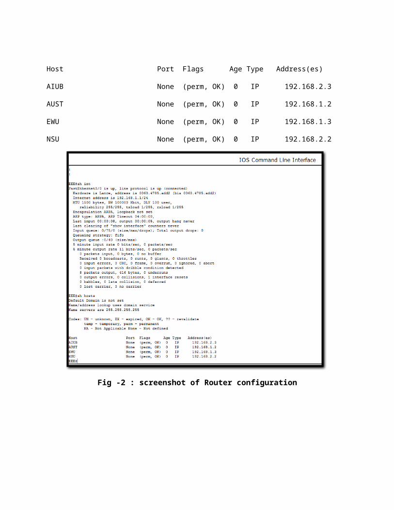
Fig -2 : screenshot of Router configuration
Fig -3 : Successful reply for PC AUST

Fig -4 : Successful reply for PC EWU
Fig -5 : Successful reply for PC NSU
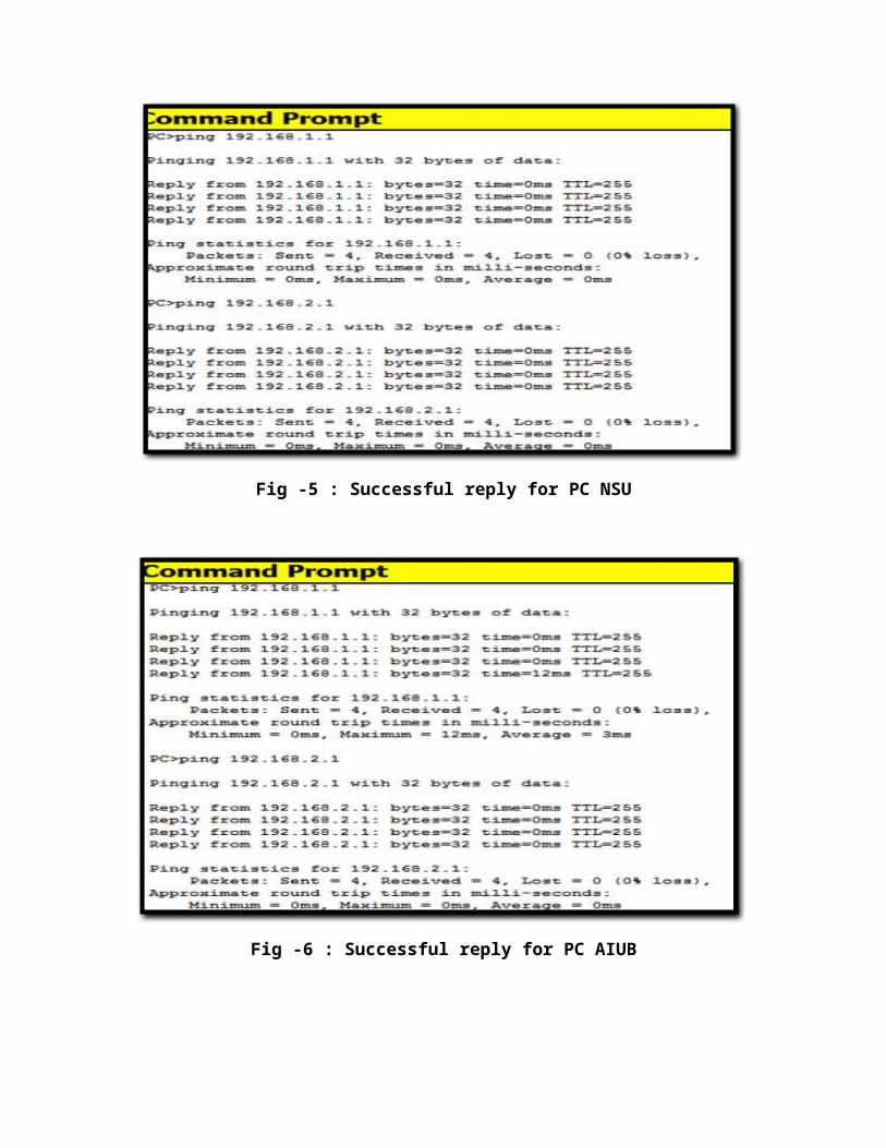
Fig -6 : Successful reply for PC AIUB
Fig -7 : Successful Sending operation in Realtime with PDU list

Fig-8: Sending process in simulation when operation is in process
Fig-9: Sending process in simulation when operation is successful

Comments :
We connect four computer,two switch and one router.Configured all the PC.And to configured the Router we go to the Router CLI and write down the commend on it step by step.And we successfully done it.To check the connection we ping from all PC’’s with both IP address and get reply from it.Finally we send packet to one PC to another and all packets are successfully sends.
Basic Router configuration :
Step-1 : Connecting Router with the PC/Laptop
Connect the console or rollover cable to the router console port,an RJ-45 connector.Next connect the other end of the console or rollover cable to the RJ-45 or RJ-45 to DB-25 adapter depending on the available PC serial port.Finally attached the adepter to a PC serial port,either DB-9 DB-25,depending on the computer.
Fig-10 : Connecting diagram
Step-2 : Start HyperTerminal program :
a.Turn on the computer and router.Then
Fig -11:Turn on Hyper terminal

But in the lab we use Tera Term software to do this.
Step-3 : Name the Hyper Terminal session :
At the connection description popup enter a name in the connection name field and select OK.
Step-4 : Specify the computer connecting interface :
At the “Connect To” popup use the drop down arrow in the Connect using field to select COM-1 and Select OK.
Step-5 : Specify the interface connection properties :
a.At the COM-1 Properties use the drop down arrow to select.
Bit per second :9600
Data bits : 8
Parity : None
Stop bit : 1
Flow control : None
Then select OK
b.The Hyper Terminal session window comes up turn on the router.If the router is already on press the enter key.There should be a respons from the router.If there is then the connection has been successfully completed.
Router Modes :
Router> User mode
Router# Privileged mode (also known as EXEC-level mode)
Router(config)# Global configuration mode
Router(config-if)# Interface mode
Router(config-subif)# Subinterface mode
Router(config-line)# Line mode
Router(config-router)# Router configuration mode

Interface:Supports commands that configure operations on a per-interface basis
Subinterface:Supports commands that configure multiple virtual interfaces on a single physical interface
Controller: Supports commands that configure controllers (for example, E1 and T1 controllers)
Line:Supports commands that configure the operation of a terminal line (for example, the console or the vty ports)
Router:Supports commands that configure an IP routing protocolIf we enter the exit command, the router backs out one level, eventually logging out. In general, we enter the exit command from one of the specific configuration modes to return to global configuration mode. Press Ctrl+Z or enter end to leave configuration mode completely and return to the privileged EXEC mode.
Commands that affect the entire device are called global commands.The hostname and enable password commands are examples of global commands.
Discussion:
In this experiment, at first, Packet Tracer is used to simulate a computer network with four computers, two switches, and one router. A router is a computer networking device that buffers and forwards data packets across an internetwork toward their destinations, through a process known as routing. A router acts as a junction between two or more networks to buffer and transfer data packets among them. A router is different from a switch. A router works on layer 3 of OSI model, while a switch works on layer 2. This experiment gives us a hand on experience of using Packet Tracer for simulating a computer network and pinging from one network’s PC to another network’s PC. While sending PDU from one PC to another, the process became failed sometimes. It happened because the network needs a minimal time to synchronous all the devices. But after trying some more times the PDU could successfully be transferred between the PCs.
Conclusion :
In this lab we learn about the router configuration.Now we are able to setup a router and properly configured it.It was very interesting lab its extend our knowledge about computer networking.