Embed Size (px)
Citation preview
Unit-5
Miscellaneous Converters &
Control Schemes
EE-321 N
Lecture-14
Cosine Control Scheme

Introduction
• A power electronic converter is useful only when its output voltage is controllable
• There are different techniques available for controlling the output of different converters like time ratio control for DC choppers, PWM control for inverters etc.
• For phase controlled rectifiers the technique is control of switching angle
9-Nov-12 EE-321N, Lec-14 3
Contd...
• Moreover, the previously described techniques (Unit-2) are not suitable if the converter has more than one thyristor (which is generally the case)
• The schemes employed for switching angle control are:
1. Cosine wave crossing control
2. Ramp comparator control
3. Digital firing scheme
4. Equidistant pulse firing scheme
9-Nov-12 EE-321N, Lec-14 4
1. Cosine Control
• This method employs a cosine wave obtained from the input supply thru an integrator.
• The cosine wave is compared against a dc reference signal and correspondingly trigger pulses are obtained
• The basic principle is similar to that of a dual converter in which output voltage ratio is equal to cosine of the firing angle
• Based on this the rectifier can be thought of as a amplifier with linear transfer characteristic
9-Nov-12 EE-321N, Lec-14 5

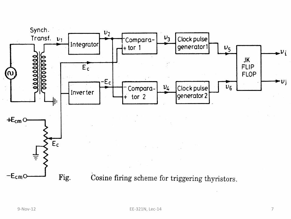
Block Diagram
9-Nov-12 EE-321N, Lec-14 6
9-Nov-12 EE-321N, Lec-14 7
Waveforms
9-Nov-12 EE-321N, Lec-14 8

9-Nov-12 EE-321N, Lec-14 9
9-Nov-12 EE-321N, Lec-14 10
Operation
• The input supply is synchronized and stepped down through a synchronizing t/f to obtain v1
• Then it is fed to integrator to obtain the cosine signal v2
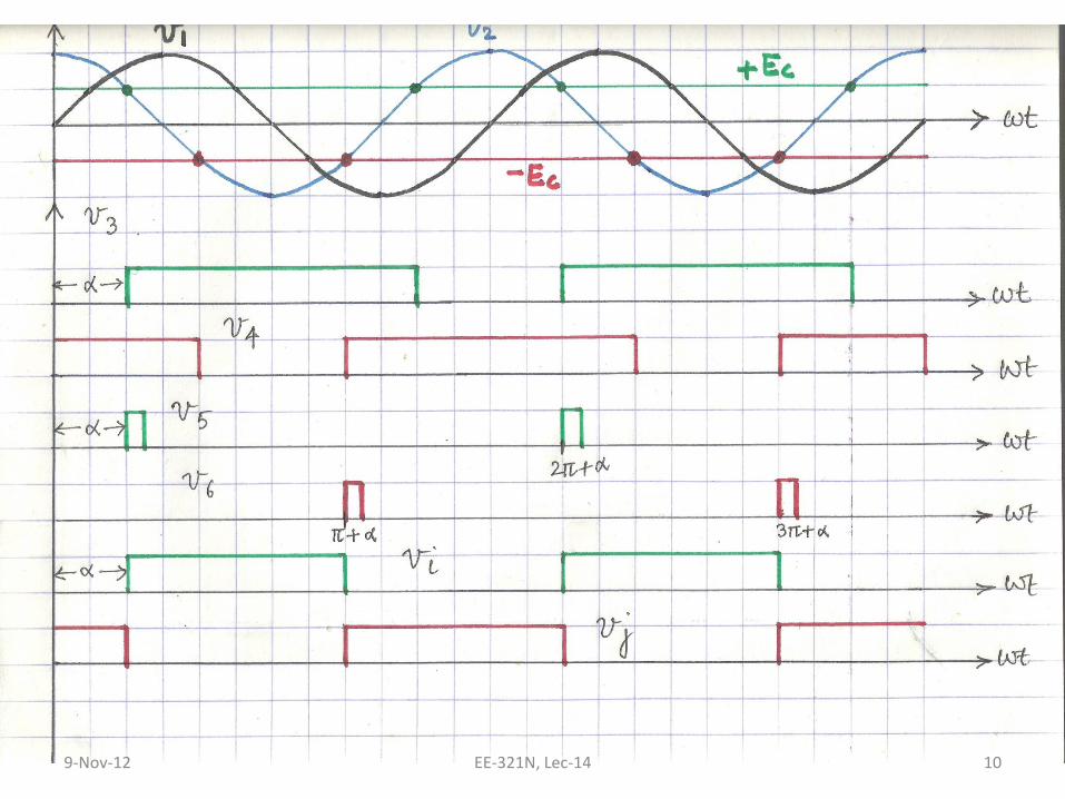
• This cosine wave is compared against the dc control voltage which is limited to ±Ecm
• v3 is the o/p of comparator 1 which is obtained when Ec is higher than v2
9-Nov-12 EE-321N, Lec-14 11
Operation...contd
• Similarly, output v4 is obtained from comparator 2.
• The signals v3 & v4 make the clock pulse generators to produce output pulses which in turn set the respective F/Fs
• The o/ps vi & vj of the F/Fs can be used to trigger SCRs in a single phase converter
• In practice, F/F outputs are ANDed with high frequency carrier wave (3-5 kHz) to obtain pulse train
9-Nov-12 EE-321N, Lec-14 12
Relation between Output Voltage & Control Voltage
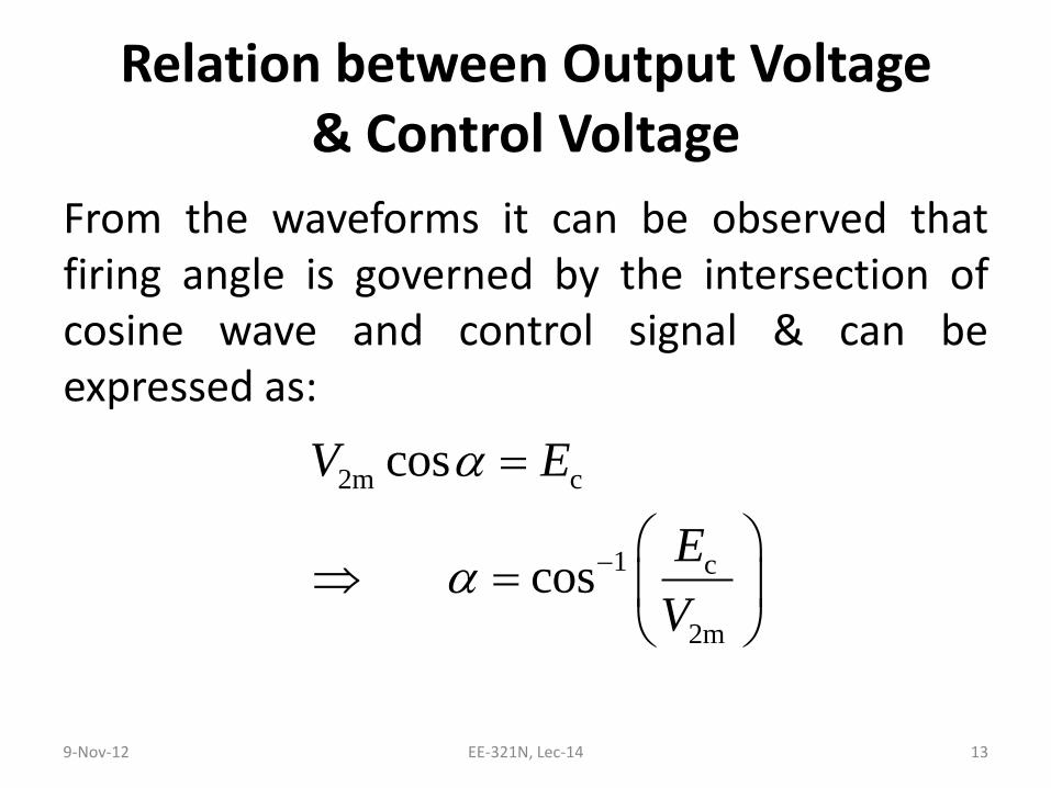
From the waveforms it can be observed that firing angle is governed by the intersection of cosine wave and control signal & can be expressed as:
9-Nov-12 EE-321N, Lec-14 13
2m c
1 c
2m
cos
cos
V E
E
V
Contd...
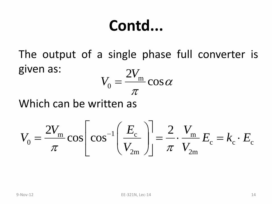
The output of a single phase full converter is given as:
Which can be written as
9-Nov-12 EE-321N, Lec-14 14
m0
2cos
VV
1 cm m0 c c c
2m 2m
2 2cos cos
EV VV E k E
V V
Contd...
This shows that cosine control scheme provides a linear transfer characteristic which improves the closed loop response of the converter
9-Nov-12 EE-321N, Lec-14 15
Remark 1
• This scheme is sensitive to line supply variations. For 3 ph converters adjustments should be made to equalize all the line voltages otherwise firing angles will be unequal
• But this scheme has a “self-regulating” property because any change in the input voltage will lead to corresponding change in the cosine wave leading to mean dc voltage being constant
9-Nov-12 EE-321N, Lec-14 16
Remark 2
• The size of the control scheme circuit increases as the number of phases/pulses increases because firing pulse is produced individually for each thyristor
• This can be overcome by using a cosine time multiplexing instead of individual timing control
• Cosine control scheme also applies to dual and cycloconverters
9-Nov-12 EE-321N, Lec-14 17
Further Reading
1. Dubey, G. K., et. al. , “Thyristorized Power Controllers”, New-Age International, 1986.
2. Pelley, B. R., “Thyristor Phase-Controlled Converters & Cycloconverters”. Wiley-Interscience, 1971.
3. Arora, O. P., “Power Electronics Laboratory: Theory, Practice & Organization ”, Narosa Publishing House, 2007.
9-Nov-12 EE-321N, Lec-14 18