Embed Size (px)
Citation preview
KITE WIND GENERATOR
CHAPTER 1: INTRODUCTION
1.1 BACKGROUND
To overcome the limitations of current wind power technology, the KiteGen project
was initiated at Politecnico di Torino to design and build a new class of wind energy
generators in collaboration with Sequoia Automation, Modelway, and Centro
StudiIndustriali.The project focusis to capture wind energy by means of controlled
tethered airfoils, that is, kites; The KiteGen project has designed and simulated a small-
scale prototype ,The two kite lines are rolled around two drums and linked to two electric
drives, which are fixed to the ground. The flight of the kite is con- trolled by regulating
the pulling force on each line. Energy is collected when the wind force on the kite unrolls
the lines, and the electric drives act as generators due to the rotation of the drums. When
the maximal line length of about 300 m is reached, the drives act as motors to recover the
kite, spending a small percentage of the previously
This yo-yo configuration is under the control of the kite steering unit,which includes the
electric drives, the drums, and all of the hardware needed to control a single kite. The
aims of the prototype are to demonstrate the abil- ity to control the flight of a single kite,
to produce a signifi- cant amount of energy, and to verify the energy production levels
predicted in simulation studies
India is the home of 1.25 billon people i.e. 17.5% of the total world population,
which makes it second most populous country in world. India has the second fastest
growing economy of the world. India’s substantial and sustained economic growth over
the years is placing enormous demand on its energy resources. The electricity sector in
India had an installed capacity of 253.389 GW as of August 2014 .India became the
world's third largest producer of electricity in the year 2013 with 4.8% global share in
electricity generation surpassing Japan and Russia. Power development in India was first
started in 1897 in Darjeeling, followed by commissioning of a hydropower station at
Sivansamudram in Karnataka during 1902. Thermal power stations which generate
electricity more than 1000 MW are referred as Super Thermal Power Stations. India's
electricity generation capacity additions from 1950 to 1985 were very low when
compared to developed nations. Since 1990, India has been one of the fastest growing
SIET VIJAYAPURA EEE DEPT Page 1
KITE WIND GENERATOR
markets for new electricity generation capacity .India's electricity generation capacity has
increased from 179 TW-h in 1985 to 1053 TW-h in 2012. Wind energy is indigenous and
helps in reducing the dependency on fossil fuels. Wind occurrence is due to the
differential heating of the earth's crust by the sun. Approximately 10 million MW of
wind energy is continuously available to India. India's Power Finance Corporation
Limited projects that current and approved electricity capacity addition projects in India
are expected to add about 100 GW of installed capacity between 2012 and 2017. This
growth makes India one of the fastest growing markets for electricity infrastructure
equipment. Of the 1.4 billion people of the world who have no access to electricity in the
world, India accounts for over 300 million. The International Energy Agency estimates
India will add between 600 GW to 1,200 GW of additional new power generation
capacity before 2050 .To fill the needs of the energy of this population, India have to
look towards non conventional energy resource which can fill a huge demand of energy
generated by the population of India. India is fulfilling its 85% of energy demand from
the conventional recourses such as coal, nuclear energy, natural gas and petroleum which
generate many greenhouse gases. Green houses gases- carbon dioxide (CO2), sulfur
dioxide (SO2), nitrous oxide (N2O) etc. are produced in the energy generation process
are not only harmful for people’s health but it also deteriorates the environment vis-à-vis
global warming and hole in the ozone layer. Thus it is the need of time that country
should look towards the green & renewable methods for the generation of energy so that
environment can be saved from those harmful effects. Wind energy, solar energy,
biomass & other renewable methods can be used for the generation of energy to fulfill
the energy demands of the country. Present paper has divided into three parts; Sources of
the wind energy in India, future scope of the wind energy in India & Conclusion. Wind
power was widely available and not confined to the banks of fast-flowing streams, or later,
requiring sources of fuel. Wind-powered pumps drained the polders of the Netherlands, and in
arid regions such as the American mid-west or the Australian outback, wind pumps provided
water for live stock and steam engines.
With the development of electric power, wind power found new applications in lighting
buildings remote from centrally-generated power. Throughout the 20th century parallel paths
developed small wind plants suitable for farms or residences, and larger utility-scale wind
generators that could be connected to electricity grids for remote use of power. Today wind
powered generators operate in every size range between tiny plants for battery charging at
SIET VIJAYAPURA EEE DEPT Page 2
KITE WIND GENERATOR
isolated residences, up to near-gigawatt sized offshore wind farms that provide electricity to
national electrical networks.
1.2MOTIVATION
A kite is traditionally a tethered heavier-than-air craft with wing surfaces that react against
the air to create lift and drag. A kite consists of wings, tethers and anchors. Kites have a
bridle to guide the face of the kite at the correct angle so the wind can lift it. A kite may have
fixed or moving anchors.
The lift that sustains the kite in flight is generated when air flows around the kite's surface,
producing low pressure above and high pressure below the wings. The interaction with the
wind also generates horizontal drag along the direction of the wind. The resultant force vector
from the lift and drag force components is opposed by the tension of one or more of the lines
or tethers to which the kite is attached. The anchor point of the kite line may be static or
moving.
The same principles of fluid flow apply in liquids and kites are also used under water.
CHAPTER 2: TYPES OF KITE WIND GENERATORS
2.1 Multiple unit kites
SIET VIJAYAPURA EEE DEPT Page 3
KITE WIND GENERATOR
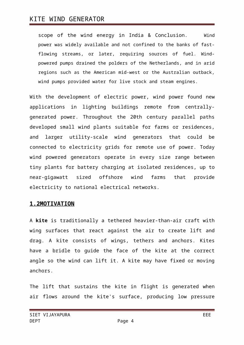
Fig 2.1Multiple unit kites
A multiple unit kite may be made of a single wing, several wings, or several sub-kite
unitsarranged as trains, chains, coterie, single-branching, multiple-branching, arch-kite,
"ladder" mill dynamic kite-chain, or combinations of these patterns. World records for the
number of kites in a kite train are in the literature; teams of people are used to fly kites of
high-count sub-kite units.Parafoil stacks have been built with over 200 kite units.
2.2 Multiple pilot
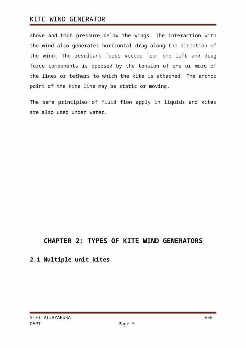
Fig 2.2Multiple pilot
Large kite systems may require more than one pilot. In a team like the "Flying Squad" of nine
kite pilots each person might fly his own sub-kite while, as a team, its kites form a unified
display. One pilot may simultaneously fly several kites; the pilot with several kites forms one
kite system of two, three or more kites in the system.
SIET VIJAYAPURA EEE DEPT Page 4
KITE WIND GENERATOR
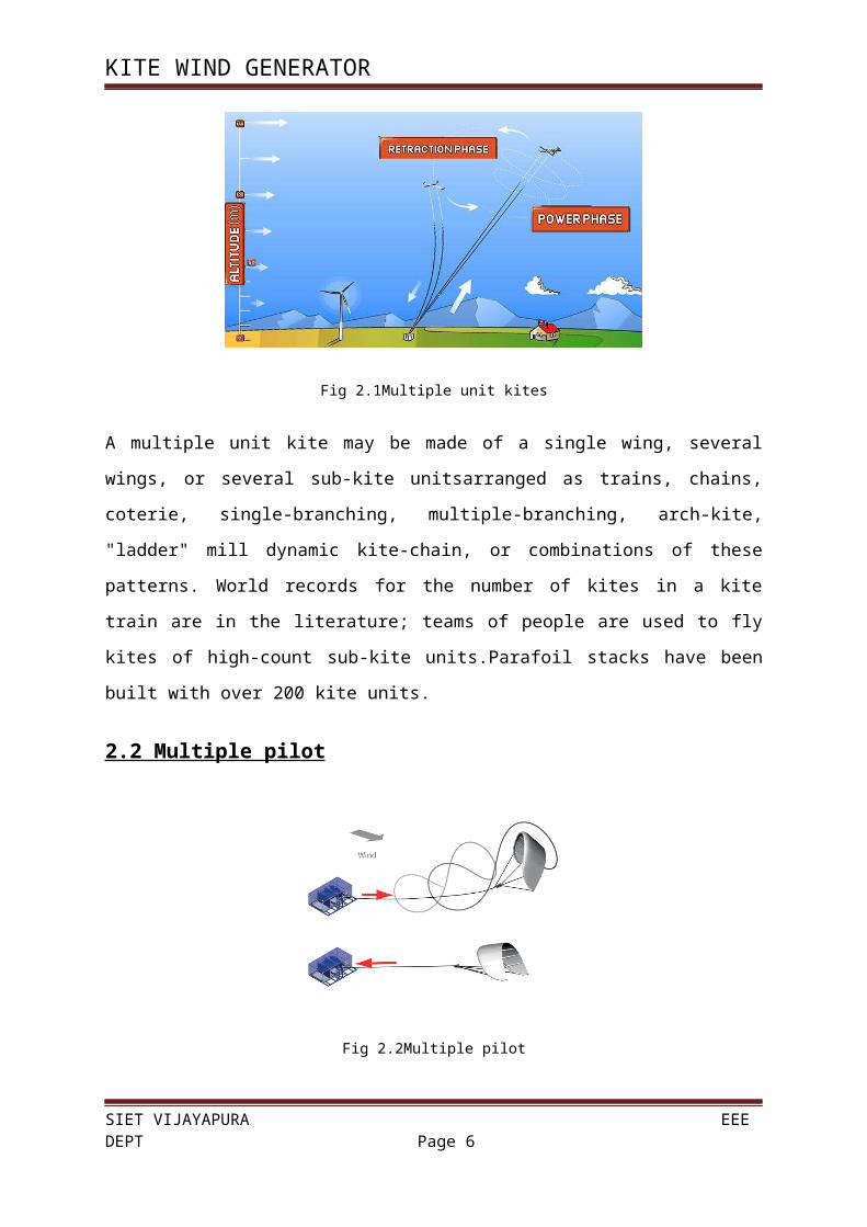
2.3 Airplane kites
Fig 2.3 Airplane kites
Large kite planes are finding an application in renewable energy generation.
2.5 Aqua-glider
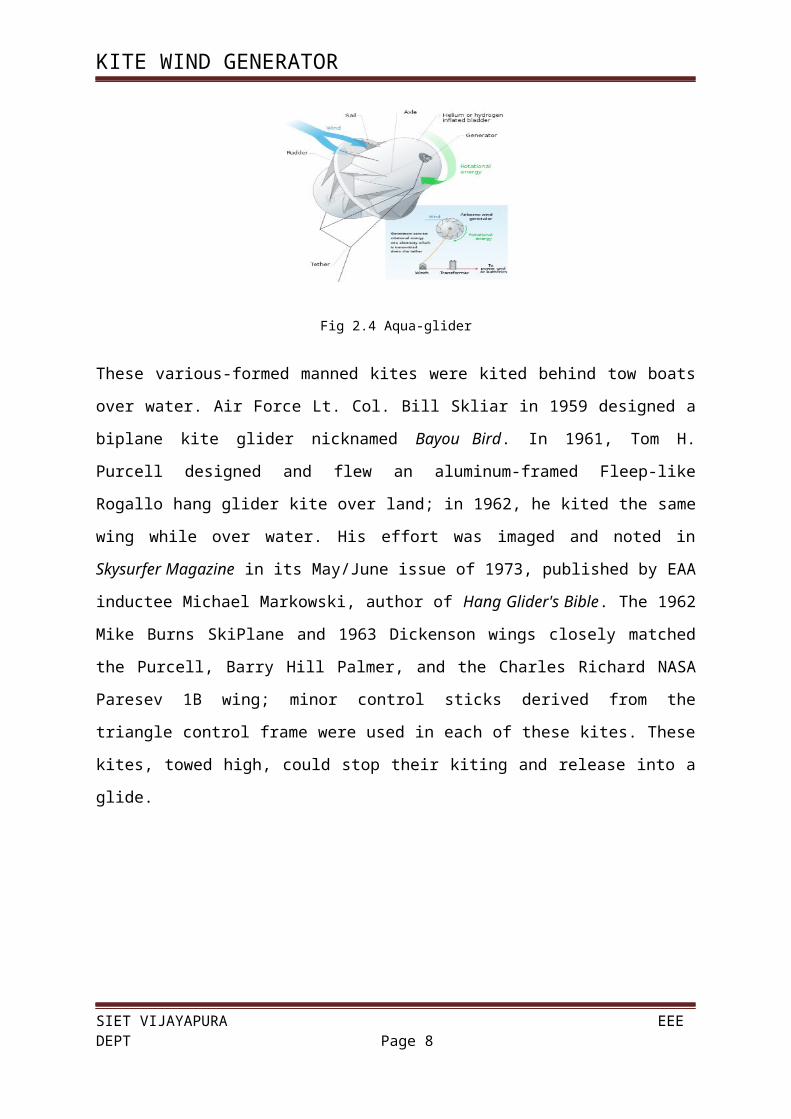
Fig 2.4 Aqua-glider
These various-formed manned kites were kited behind tow boats over water. Air Force Lt.
Col. Bill Skliar in 1959 designed a biplane kite glider nicknamed Bayou Bird. In 1961, Tom
H. Purcell designed and flew an aluminum-framed Fleep-like Rogallo hang glider kite over
land; in 1962, he kited the same wing while over water. His effort was imaged and noted in
Skysurfer Magazine in its May/June issue of 1973, published by EAA inductee Michael
Markowski, author of Hang Glider's Bible. The 1962 Mike Burns SkiPlane and 1963
Dickenson wings closely matched the Purcell, Barry Hill Palmer, and the Charles Richard
NASA Paresev 1B wing; minor control sticks derived from the triangle control frame were
SIET VIJAYAPURA EEE DEPT Page 5
KITE WIND GENERATOR
used in each of these kites. These kites, towed high, could stop their kiting and release into a
glide.
CHAPTER 3: WORKING PRINCIPLE
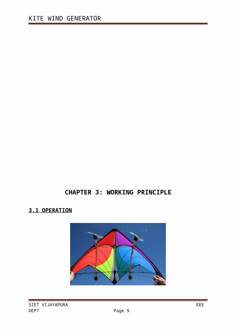
3.1 OPERATION
SIET VIJAYAPURA EEE DEPT Page 6
KITE WIND GENERATOR
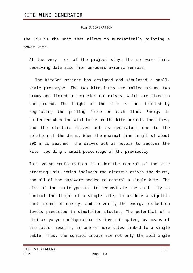
Fig 3.1OPERATION
The KSU is the unit that allows to automatically piloting a power kite.
At the very core of the project stays the software that, receiving data also from on-board
avionic sensors.
The KiteGen project has designed and simulated a small-scale prototype. The two kite
lines are rolled around two drums and linked to two electric drives, which are fixed to the
ground. The flight of the kite is con- trolled by regulating the pulling force on each line.
Energy is collected when the wind force on the kite unrolls the lines, and the electric
drives act as generators due to the rotation of the drums. When the maximal line length of
about 300 m is reached, the drives act as motors to recover the kite, spending a small
percentage of the previously
This yo-yo configuration is under the control of the kite steering unit, which includes the
electric drives the drums, and all of the hardware needed to control a single kite. The aims
of the prototype are to demonstrate the abil- ity to control the flight of a single kite, to
produce a signifi-cant amount of energy, and to verify the energy production levels
predicted in simulation studies. The potential of a similar yo-yo configuration is investi-
gated, by means of simulation results, in one or more kites linked to a single cable. Thus,
the control inputs are not only the roll angle ψ and the cable winding speed, as considered
in this article, but also the lift coefficient CL. For medium-to-large-scale energy
generators, an alter- native KiteGen configuration is being studied, namely, the carousel
configuration. In this configuration, several airfoils are controlled by their KSUs placed
on the arms of a verti- cal-axis rotor. The controller of each kite is designed to maximize
SIET VIJAYAPURA EEE DEPT Page 7
KITE WIND GENERATOR
the torque exerted on the rotor, which transmits its motion to an electric generator. For a
given wind direction, each airfoil can produce energy for about 300◦ of carousel rotation;
only a small fraction of the generated energy is used to drag the kite against the wind for
the remaining 60◦. According to our simulation results, it is estimated that the required
land usage for a kite generator may be lower than a current wind farm of the same power
by a factor of up to 30–50, with electric energy
Expert kite-surfers drive kites to obtain energy for propulsion. Control technology can be
applied to exploit this technique for electric energy generation.
The kite lines are linked to two electric drives. The flight of the kite is controlled by
regulating the pulling force on each line, and energy is generated as the kite unrolls the
lines.
The kite steering unit, which provides auto- matic control for KiteGen, includes the
electric drives, drums, and all of the hardware needed to control a single kite.
Production costs lower by a factor up to 10–20. Such potential improvement over
current wind technology is due to several aerodynamic and mechanical reasons.This
dependence is due to the fact that the aerodynamic forces on each infinitesimal section of
the blades are proportional to the square of its speed with respect to the air, and this speed
increases toward the tip of the blades. In KiteGen, the tethered airfoils act as the outer
portions of the blades, without the need for mechanical support of the tower and of the
less-productive inner blade portions. Indeed, a mean generated power of 620 kW is
obtained in the simulation reported for a single kite of 100-m2 area and 300-m line
length.
3.2 SYSTEM AND CONTROL TECHNOLOGIES NEEDED FOR
KITEGEN
3.2.1 Control Design
SIET VIJAYAPURA EEE DEPT Page 8
KITE WIND GENERATOR
The main objective of KiteGen control is to maximize energy generation
while preventing the airfoils from falling to the ground or the lines from
tangling. The control problem can be expressed in terms of maximizing a
cost function that predicts the net energy generation while satisfying
constraints on the input and state variables. Nonlinear model predictive
control (MPC) is employed to accomplish these objectives, since it aims to
optimize a given cost function and fulfill constraints at the same time.
However, fast implementation is needed to allow real-time control at the
required sampling time, which is on the order of 0.1 s. In particular, the
implementation of fast model predictive control (FMPC) based on set
membership approximation methodologies.
3.2.2 Model Identification
Optimizing performance for Kite- Gen relies on predicting the behavior
of the system dynamics as accurately as possible. However, since accurately
modeling the dynamics of a nonrigid airfoil is challenging, model-based
control design may not perform satisfactorily on the real system. In this case,
methods for identifying nonlinear systems can be applied to derive more
accurate models.
3.2.3 Sensors and Sensor Fusion
The KiteGen controller is based on feedback of the kite position and
speed vector, which must be mea- sured or accurately estimated. Each
airfoil is thus equipped with a pair of triaxial accelerometers and a pair
SIET VIJAYAPURA EEE DEPT Page 9
KITE WIND GENERATOR
fulfilled, the DVS gives the same accuracy as the theoreti-cal minimal
variance filter. Moreover, in the presence of modeling errors and
nonlinearities, the DVS guarantees stability and performs tradeoffs
between optimality and robustness, which are not achievable with EKF.
CHAPTER 4: APPLICATIONS
4.1 Teaching
The kite is frequently the vehicle for teaching aerodynamics, mathematics, art, history,
culture, materials, cooperation, physical education, and problem solving
4.2 Transport
SIET VIJAYAPURA EEE DEPT Page 10
KITE WIND GENERATOR
Long-distance travel across land, ice, and sea started centuries ago, but today significant tasks
of moving people and goods from point A to point B are occurring; this is so in great part
from the advances in kites and kite systems designs and technology, better understanding of
winds, and use of computers.In 1889 kite sailing was carefully instructed via controlling large
kite systems towing boats.
Free-flight cross-country hang gliding kites both in the hang glider style and the paraglider
style are permitting trips of hundreds of miles; records are recorded by the FAI. George
Pocock was an early pioneer in kites for transportation. NASA continues to explore free-
flying kites for delivering goods to earth surface and non-earth planet surfaces, including
Mars. There are several projects for using very large kites to sail cargo ships currently
underway: KiteSail(tm) and KiteShip along with a series of patents and improvements in
control of large ship-carried kite systems aim to save significant amounts of fuel.
4.3 Military
Kites have been used for military uses in the past for signaling, for delivery of munitions, for
free-flight kiting payloads from aircraft to ground positions, for kiting troops to points where
they could parachute to destinations, for underwater kiting via paravanes to perform various
underwater duties, for lifting payloads from one point to another, for raising rescue signals
from rafts or stressed areas, for raising communications antenna, and for observation by
lifting an observer above the field of battle, and by using kite aerial photography. Barrage
kites have been used in both open frame kites and kytoon types to defend against enemy
aircraft.
Kim Yu-Sin,a Korean general, in 637 C.E. rallied his troops to defeat rebels by kite lofting a
burning ball.Kites were also used by Admiral Yi of the Joseon Dynasty of Korea. During the
Japanese invasions of Korea , Admiral Yi commanded his navy with kites. His kites had
specific markings directing his fleet to perform his order. Admiral Yi was said to have over
300 such kites. The war eventually resulted in a Chinese and Korean victory; the kites played
a minor role in the war's conclusion.
4.4 Energy generation
SIET VIJAYAPURA EEE DEPT Page 11
KITE WIND GENERATOR
Both air and hydro kites are used to generate electricity; the kite is set in the stream of air or
water; various schemes are used to extract some of the stream's energy for converting that
energy to electricity.
A major research and development project called Makani Power, based in California and
funded by Google.org, is investigating the use of kites in harnessing high altitude wind
currents to generate electricity.Tidal kites operate underwater, using the tidal stream's greater
mass to generate far more electricity than available in wind-borne environments.
CHAPTER 5: ADVANTAGES & DISADVANTAGES
5.1 Advantages
The wind is free and with modern technology it can be captured efficiently
Once the wind turbine is built the energy it produces does not cause green house gases
or other pollutants
Although wind turbines can be very tall each takes up only a small plot of land. This
means that the land below can still be used. This is especially the case in agricultural
areas as farming can still continue
SIET VIJAYAPURA EEE DEPT Page 12
KITE WIND GENERATOR
Many people find wind farms an interesting feature of the landscape
Remote areas that are not connected to the electricity power grid can use wind
turbines to produce their own supply
Wind turbines have a role to play in both the developed and third world
5.2 Disadvantages The strength of the wind is not constant and it varies from zero to storm force. This
means that wind turbines do not produce the same amount of electricity all the time.
There will be times when they produce no electricity at all.
Many people feel that the countryside should be left untouched, without these large
structures being built. The landscape should left in its natural form for everyone to
enjoy
Wind turbines are noisy. Each one can generate the same level of noise as a family car
travelling at 70 mph
Many people see large wind turbines as unsightly structures and not pleasant or
interesting to look at. They disfigure the countryside and are generally ugly
When wind turbines are being manufactured some pollution is produced. Therefore
wind power does produce some pollution
Large wind farms are needed to provide entire communities with enough electricity.
For example, the largest single turbine available today can only provide enough
electricity for 475 homes, when running at full capacity.
CHAPTER 6: FUTURE SCOPE & CONCLUSION
6.1 Future scope
Trading torque for tension
Pumping
Changing tacks
Blowing in the wind
Military
6.2 conclusion
SIET VIJAYAPURA EEE DEPT Page 13
KITE WIND GENERATOR
Fig 6.2
It is a new class of wind energy generators able to overcome the main
limitations of the present Aeolian technology based on wind mills.
REFERENCE
1. "About KiteGen". 2010-05-08. Retrieved 2011-03-15.
2. Bardi, Ugo (2010-06-10). "Da Berzano, ilkitegen in costruzione"Retrieved2011-03-
15.
3. "Flugdrachen-SegelerzeugtbilligeWindenergie" [Kite produces cheap wind energy]
(in German). 2009-10-30. Retrieved 2011-03-15.
4. "A big energy reservoir: the altitude wind". Retrieved 2011-03-15.
5. "Kite Gen". Retrieved 2011-03-15.
6. "Kite Gen: KonzeptversprichtbilligeWindenergie" (in German). 2009-10-28.
Retrieved 16 March 2011.
7. "NASA untersuchtMöglichkeitfürWindfarmen in luftigenHöhen" (in German). 2010-
12-22. Retrieved 15 March 2011.
SIET VIJAYAPURA EEE DEPT Page 14
KITE WIND GENERATOR
8. "Campagna "ScoprireilNucleare"" (in Italian). 2011-03-01. Retrieved 16 March
2011.
9. Jewkes, Stephen; Lalor, Dan (12 September 2012). "Third buyer interested in Alcoa
Sardinia smelter". Reuters. Retrieved 27 September 2012.
10. Sapellani, Niccolò(20 September 2012). "Alcoa, ilterzopretendente è la KiteGen:
"Produrrealluminioutilizzandoilvento". IlFattoQuotidiano. Retrieved 27 September
2012.
11. Jucca, Lisa "Italy's Sardinia struggles to leave state aid behind". Reuters. Retrieved
27 September 2012
SIET VIJAYAPURA EEE DEPT Page 15


![Optimal Control of Power Kites for Wind Power Productionee08225/wp-content/uploads/... · 2014-02-18 · (c) Wind generator kite system [18]. (d) Airship-floated wind turbine [19]](https://img.pdfslide.us/doc/110x75/5fa1f6495621030a8f24a1af/optimal-control-of-power-kites-for-wind-power-production-ee08225wp-contentuploads.jpg)