Embed Size (px)
Citation preview
IT6601 MOBILE COMPUTING
UNIT – II
Dr.A.Kathirvel, Professor and Head, Dept of IT
Anand Institute of Higher Technology, Chennai
Unit - II
MOBILE INTERNET PROTOCOL AND TRANSPORT LAYER
Overview of Mobile IP – Features of Mobile IP – Key Mechanism in
Mobile IP – route Optimization. Overview of TCP/IP – Architecture
of TCP/IP- Adaptation of TCP Window – Improvement in TCP
Performance.
*Prasant Kumar Pattnaik, Rajib Mall, “Fundamentals of Mobile Computing”, PHI Learning Pvt. Ltd, New Delhi
2
Why Mobile IP?
What do cellular networks and wireless LANs provide?
Wireless connectivity
Mobility at the data link layer
What is Dynamic Host Configuration Protocol (DHCP)?
It provides local IP addresses for mobile hosts
Is not secure
Does not maintain network connectivity when moving around
What they do not provide:
Transparent connectivity at the network layer
Mobility with local access
The difference between mobility and nomadicity!
3
What is Mobile IP?
Mobile IP provides network layer
mobility
Provides seamless roaming
‘‘Extends’’ the home network over
the entire Internet
4
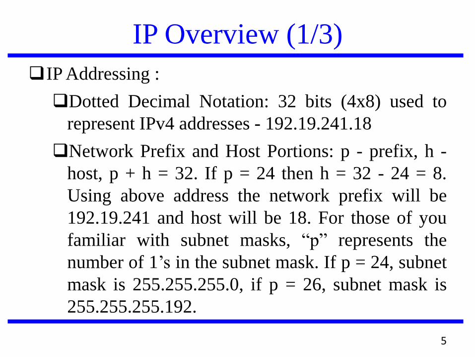
IP Overview (1/3)
IP Addressing :
Dotted Decimal Notation: 32 bits (4x8) used to
represent IPv4 addresses - 192.19.241.18
Network Prefix and Host Portions: p - prefix, h -
host, p + h = 32. If p = 24 then h = 32 - 24 = 8.
Using above address the network prefix will be
192.19.241 and host will be 18. For those of you
familiar with subnet masks, “p” represents the
number of 1’s in the subnet mask. If p = 24, subnet
mask is 255.255.255.0, if p = 26, subnet mask is
255.255.255.192.
5
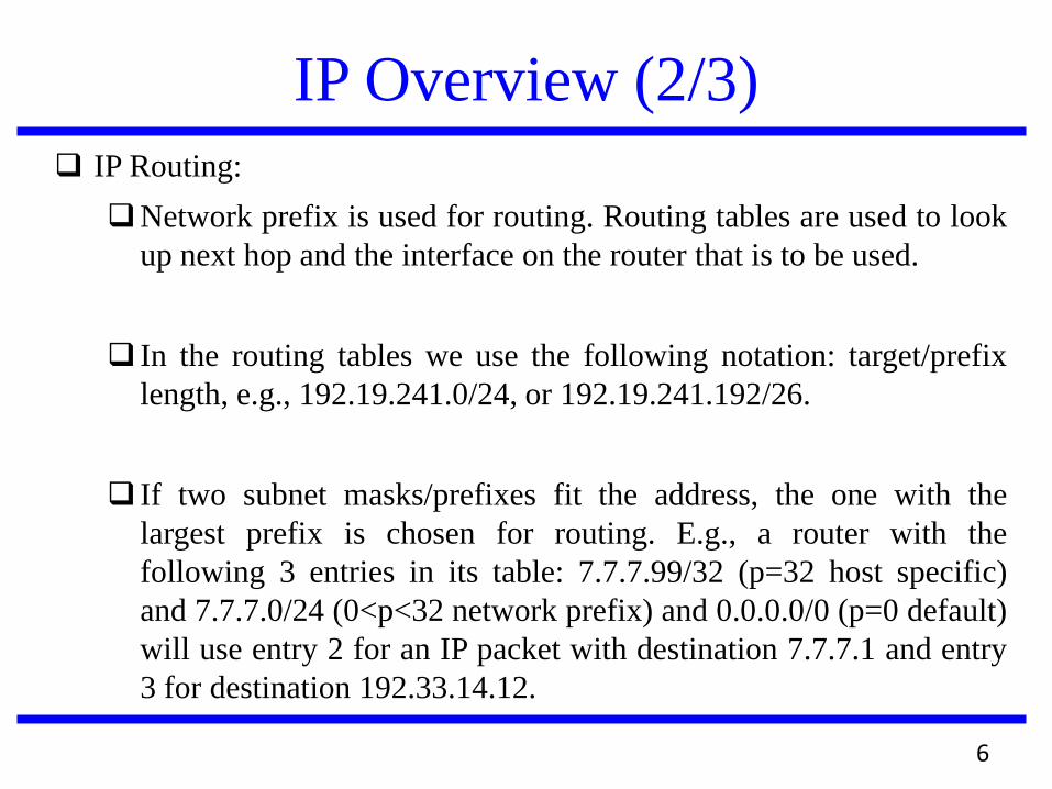
IP Overview (2/3)
IP Routing:
Network prefix is used for routing. Routing tables are used to look
up next hop and the interface on the router that is to be used.
In the routing tables we use the following notation: target/prefix
length, e.g., 192.19.241.0/24, or 192.19.241.192/26.
If two subnet masks/prefixes fit the address, the one with the
largest prefix is chosen for routing. E.g., a router with the
following 3 entries in its table: 7.7.7.99/32 (p=32 host specific)
and 7.7.7.0/24 (0<p<32 network prefix) and 0.0.0.0/0 (p=0 default)
will use entry 2 for an IP packet with destination 7.7.7.1 and entry
3 for destination 192.33.14.12.
6
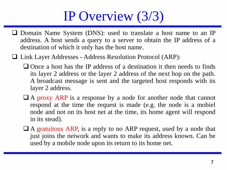
IP Overview (3/3) Domain Name System (DNS): used to translate a host name to an IP
address. A host sends a query to a server to obtain the IP address of a destination of which it only has the host name.
Link Layer Addresses - Address Resolution Protocol (ARP):
Once a host has the IP address of a destination it then needs to finds its layer 2 address or the layer 2 address of the next hop on the path. A broadcast message is sent and the targeted host responds with its layer 2 address.
A proxy ARP is a response by a node for another node that cannot respond at the time the request is made (e.g. the node is a mobiel node and not on its host net at the time, its home agent will respond in its stead).
A gratuitous ARP, is a reply to no ARP request, used by a node that just joins the network and wants to make its address known. Can be used by a mobile node upon its return to its home net.
7
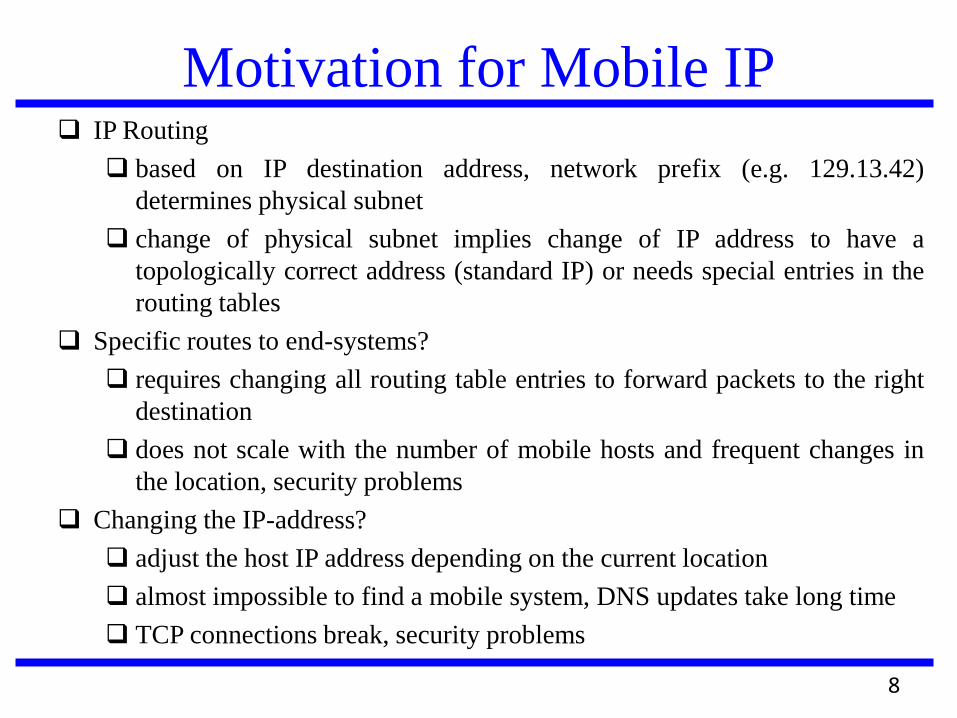
Motivation for Mobile IP IP Routing
based on IP destination address, network prefix (e.g. 129.13.42)
determines physical subnet
change of physical subnet implies change of IP address to have a
topologically correct address (standard IP) or needs special entries in the
routing tables
Specific routes to end-systems?
requires changing all routing table entries to forward packets to the right
destination
does not scale with the number of mobile hosts and frequent changes in
the location, security problems
Changing the IP-address?
adjust the host IP address depending on the current location
almost impossible to find a mobile system, DNS updates take long time
TCP connections break, security problems
8
What Mobile IP does? Mobile IP solves the following problems:
if a node moves without changing its IP address it will be unable to receive its packets,
if a node changes its IP address it will have to terminate and restart its ongoing connections everytime it moves to a new network area (new network prefix).
Mobile IP is a routing protocol with a very specific purpose.
Mobile IP is a network layer solution to node mobility in the Internet.
Mobile IP is not a complete solution to mobility, changes to the transport protocols need to be made for a better solution (i.e., the transport layers are unaware of the mobile node’s point of attachment and it might be useful if, e.g., TCP knew that a wireless link was being used!).
9
Requirements to Mobile IP Transparency
mobile end-systems keep their IP address
continuation of communication after interruption of link possible
point of connection to the fixed network can be changed
Compatibility
support of the same layer 2 protocols as IP
no changes to current end-systems and routers required
mobile end-systems can communicate with fixed systems
Security
authentication of all registration messages
Efficiency and scalability
only little additional messages to the mobile system required (connection typically via a low bandwidth radio link)
world-wide support of a large number of mobile systems in the whole Internet
10
Mobile IP Terminology Mobile Node (MN)
system (node) that can change the point of connection to the
network without changing its IP address
Home Agent (HA)
system in the home network of the MN, typically a router
registers the location of the MN, tunnels IP datagrams to the COA
Foreign Agent (FA)
system in the current foreign network of the MN, typically a router
forwards the tunneled datagrams to the MN, typically also the
default router for the MN
Care-of Address (COA)
address of the current tunnel end-point for the MN (at FA or MN)
actual location of the MN from an IP point of view
can be chosen, e.g., via DHCP
Correspondent Node (CN)
communication partner 11
Properties of COA
A care-of address is an IP address associated with mobile node that is visiting a foreign link:
A care-of address is specific to the foreign link currently being visited by a mobile node
Generally changes every time the mobile node moves from one foreign link to another
No Mobile IP-specific procedures are needed in order to deliver packets to a care-of address
Is used as the exit-point of a tunnel from the home agent toward the mobile node
Is never returned by DNS when another node looks up the mobile node’s hostname
12
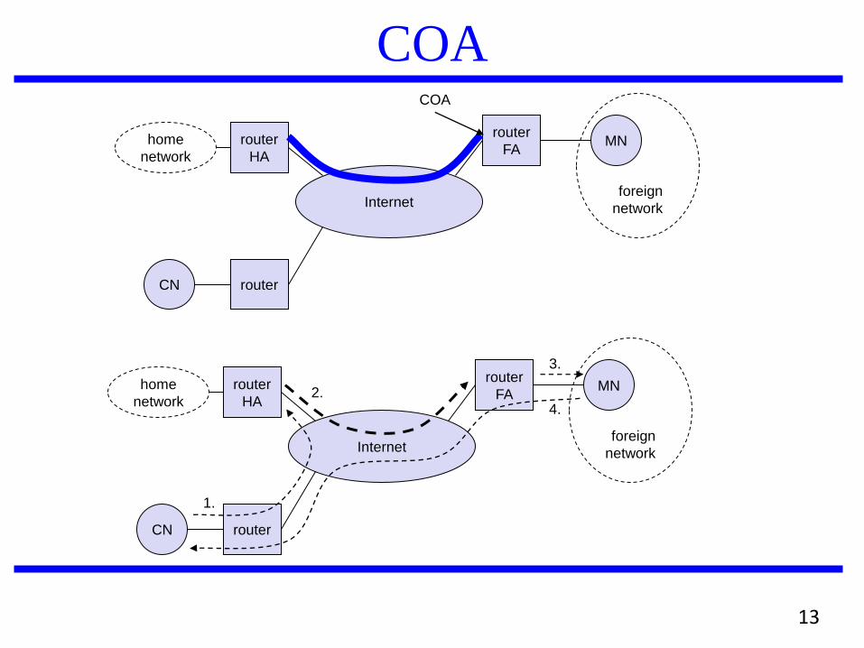
COA
CN
router
HA
router
FA
Internet
router
1.
2.
3.
home
network MN
foreign
network
4.
CN
router
HA
router
FA
Internet
router
home
network MN
foreign
network
COA
13
Types of COA
A foreign agent care-of address is an IP address of a foreign
agent which has an interface on the foreign link being visited
by a mobile node. Can be shared by many mobile nodes
simultaneously
A collocated care-of address is an IP address temporarily
assigned to an interface of the mobile node itself. The
network-prefix of a collocated care-of address must equal the
network-prefix that has been assigned to the foreign link being
visited by a mobile node. This type of c/o address might be
used by mobile node in situations where no foreign agents are
available on a foreign link. A collocated c/o address can be
used by only one mobile node at a time
14
Mobile IP Features
Allows a host to be reachable at the same
address, even as it changes its location
makes it seem as one network extends over
the entire Internet
continuous connectivity, seamless roaming
even while network applications are running
fully transparent to the user
15
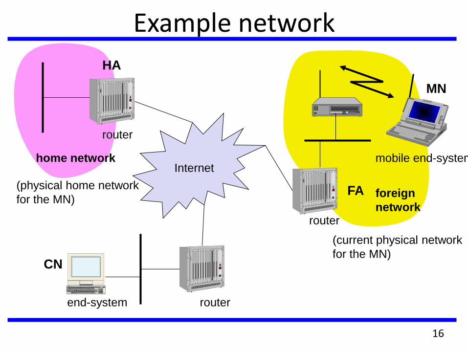
Example network
mobile end-system Internet
router
router
router
end-system
FA
HA
MN
home network
foreign
network
(physical home network
for the MN)
(current physical network
for the MN) CN
16
Key Mechanism in Mobile IP
Home Agents and Foreign Agents advertise their presence on
any attached links by periodically multicasting or broadcasting
special Mobile IP messages called Agent Advertisements
Mobile Nodes listen to these Agent Advertisements and
examine their contents to determine whether they are
connected to their home link or a foreign link
A Mobile Node connected to a foreign link acquires a care-of
address. A foreign agent care-of address can be read from one
of the fields within the foreign agent’s Agent Advertisement. A
collocated care-of address must be acquired by some
assignment procedure, such as Dynamic Host Configuration
Protocol (DHCP), the Point-to-Point Protocol’s IP Control
Protocol (IPCP), or manual configuration
17
Data transfer to the mobile system
Internet
sender
FA
HA
MN
home network
foreign
network
receiver
1
2
3
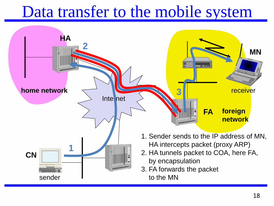
1. Sender sends to the IP address of MN,
HA intercepts packet (proxy ARP)
2. HA tunnels packet to COA, here FA,
by encapsulation
3. FA forwards the packet
to the MN
CN
18
Data transfer from the mobile system
Internet
receiver
FA
HA
MN
home network
foreign
network
sender
1
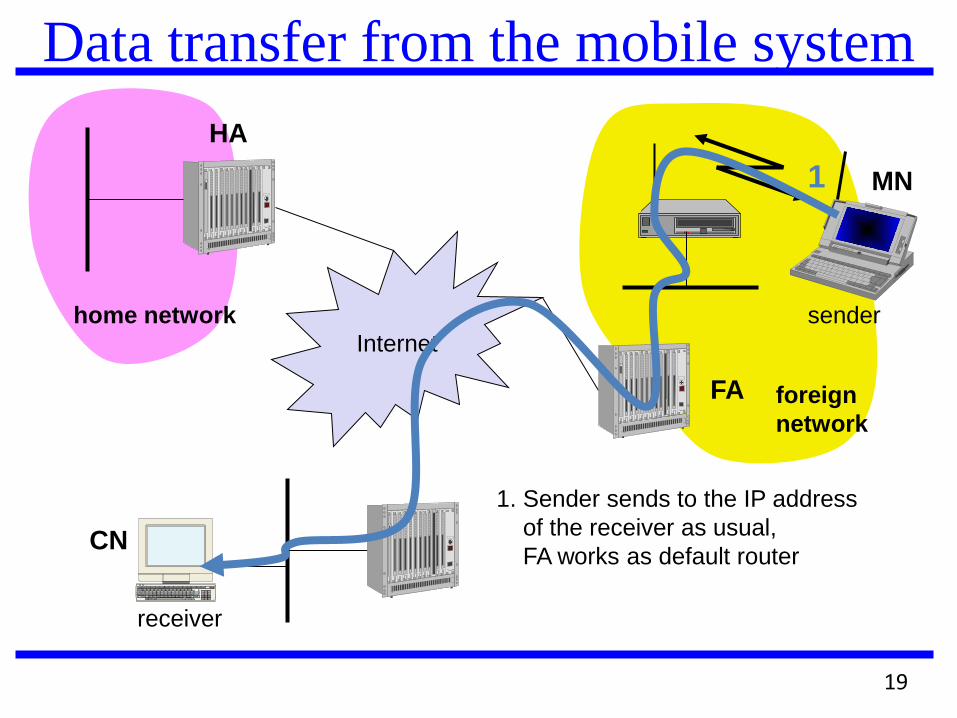
1. Sender sends to the IP address
of the receiver as usual,
FA works as default router CN
19
Key Mechanism in Mobile IP The mobile IP Registers the care-of address acquired previously with its
home agent, using a message-exchange defined by Mobile IP. It asks for service from a Foreign Agent, if one is present on the link. In order to prevent Denial-of-Service attacks, the registration messages are required to be authenticated
The Home Agent or some other router on the home link advertises reachability to the network-prefix of the Mobile Node’s home address, thus attracting packets that are destined to the Mobile Node’s home address. The Home Agent intercepts these packets, and tunnels them to the care-of address that the mobile node registered previously
At the care-of address – at either the Foreign Agent or one of the interfaces of the mobile node itself – the original packet is extracted from the tunnel and then delivered to the Mobile Node
In the reverse direction, packets sent by the Mobile Node are routed directly to their destination, without any need for tunneling. The Foreign Agent serves as a default router for all packets generated by visiting node
20
Route Optimization
Triangle Routing: tunneling in its simplest form has all packets go to home network (HA) and then sent to MN via a tunnel.
This involves two IP routes that need to be set-up, one original and the second the tunnel route.
Causes unnecessary network overhead and adds to the latency.
Route optimization: allows the correspondent node to learn the current location of the MN and tunnel its own packets directly. Problems arise with
mobility: correspondent node has to update/maintain its cache.
authentication: HA has to communicate with the correspondent node to do authentication, i.e., security association is with HA not with MN.
21
Optimization of Packet Forwarding
Change of FA
packets on-the-fly during the change can be
lost
new FA informs old FA to avoid packet loss,
old FA now forwards remaining packets to
new FA
this information also enables the old FA to
release resources for the MN
22
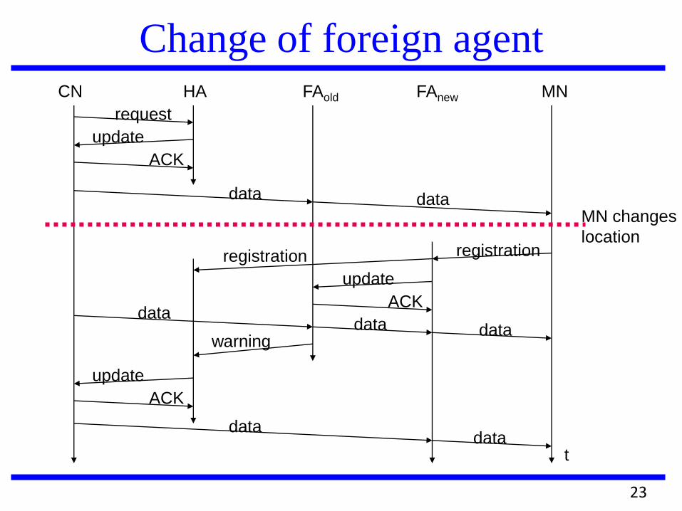
Change of foreign agent CN HA FAold FAnew MN
t
request
update
ACK
data data MN changes
location registration
update
ACK data
data data warning
update
ACK
data data
registration
23
Problems with Triangle Routing
Triangle routing has the MN correspond directly with the CN
using its home address as the SA
Firewalls at the foreign network may not allow that
Multicasting: if a MN is to participate in a multicast group, it
needs to use a reverse tunnel to maintain its association with
the home network.
TTL: a MN might have a TTL that is suitable for
communication when it is in its HM. This TTL may not be
sufficient when moving around (longer routes possibly). When
using a reverse tunnel, it only counts as a single hop. A MN
does not want to change the TTL everytime it moves.
Solution: reverse tunneling
24
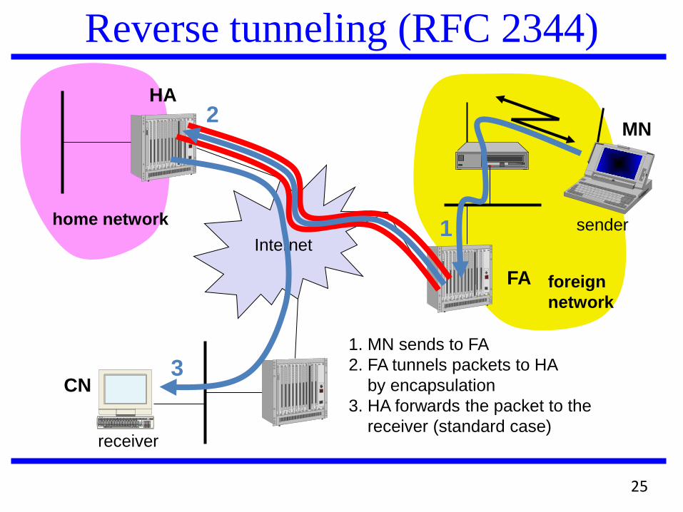
Reverse tunneling (RFC 2344)
Internet
receiver
FA
HA
MN
home network
foreign
network
sender
3
2
1
1. MN sends to FA
2. FA tunnels packets to HA
by encapsulation
3. HA forwards the packet to the
receiver (standard case)
CN
25
Mobile IP with reverse tunneling
Routers accept often only “topologically correct“ addresses
(firewall!)
a packet from the MN encapsulated by the FA is now
topologically correct
Multicast and TTL problems solved
Reverse tunneling does not solve
all problems with firewalls, the reverse tunnel can be abused to
circumvent security mechanisms (tunnel hijacking)
optimization of data paths, i.e. packets will be forwarded through
the tunnel via the HA to a sender (longer routes)
The new standard is backwards compatible
the extensions can be implemented easily
26
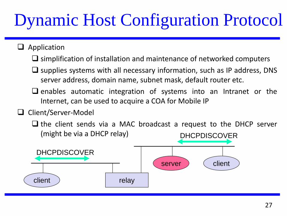
Dynamic Host Configuration Protocol
Application
simplification of installation and maintenance of networked computers
supplies systems with all necessary information, such as IP address, DNS server address, domain name, subnet mask, default router etc.
enables automatic integration of systems into an Intranet or the Internet, can be used to acquire a COA for Mobile IP
Client/Server-Model
the client sends via a MAC broadcast a request to the DHCP server (might be via a DHCP relay)
client relay
client server
DHCPDISCOVER
DHCPDISCOVER
27
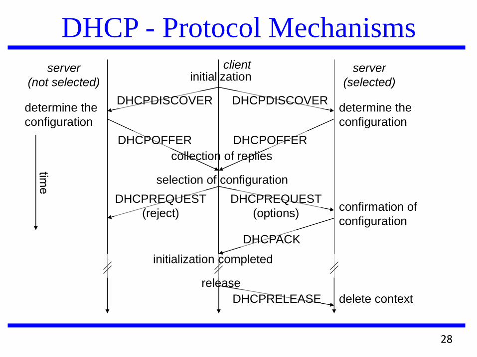
DHCP - Protocol Mechanisms
server
(not selected)
client server
(selected) initialization
collection of replies
selection of configuration
initialization completed
release
confirmation of
configuration
delete context
determine the
configuration
DHCPDISCOVER
DHCPOFFER
DHCPREQUEST
(reject)
DHCPACK
DHCPRELEASE
DHCPDISCOVER
DHCPOFFER
DHCPREQUEST
(options)
determine the
configuration
28
DHCP characteristics
Server
several servers can be configured for DHCP, coordination not
yet standardized (i.e., manual configuration)
Renewal of configurations
IP addresses have to be requested periodically, simplified
protocol
Options
available for routers, subnet mask, NTP (network time
protocol) timeserver, SLP (service location protocol)
directory, DNS (domain name system)
Big security problems!
no authentication of DHCP information specified
29
Mobile IP Summary Allows node mobility across media of similar or dissimilar types
Uses the Mobile Node’s permanent home address when it changes its point of attachment to the Internet
Not requires any hardware and software upgrades to the existing, installed base of IPv4 hosts and routers – other than those nodes specifically involved in the provision of mobility services
Mobile Node must provide strong authentication when it informs its Home Agent of its current location
Uses tunneling to deliver packets that are destined to the Mobile Node’s home address
3 main entities: Mobile Nodes, Foreign Agents and Home Agents
3 basic functions: Agent Discovery, Registration, Packet Routing
30
Origins of TCP/IP
Transmission Control Protocol/Internet Protocol
(TCP/IP)
Resulted from a coordinated effort by the U.S. Department
of Defense (DOD)
Advanced Research Projects Agency (ARPA)
Charged with creating a wide area network (WAN)
Results were TCP/IP and ARPANET
DOD funded two projects
The adaptation of TCP/IP to work with UNIX
The inclusion of the TCP/IP protocol with Berkeley UNIX
(BSD UNIX)
31
Overview of TCP/IP
Reliable, full-duplex, connection-
oriented, stream delivery
Interface presented to the application
doesn’t require data in individual packets
Data is guaranteed to arrive, and in the
correct order without duplications
Or the connection will be dropped
Imposes significant overheads
32
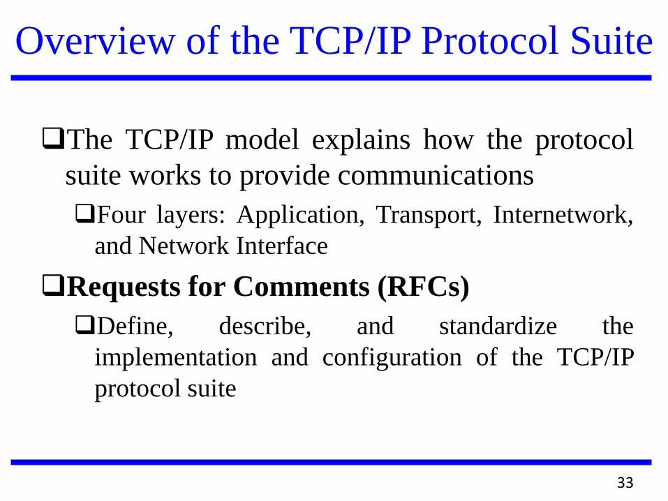
Overview of the TCP/IP Protocol Suite
The TCP/IP model explains how the protocol
suite works to provide communications
Four layers: Application, Transport, Internetwork,
and Network Interface
Requests for Comments (RFCs)
Define, describe, and standardize the
implementation and configuration of the TCP/IP
protocol suite
33
34
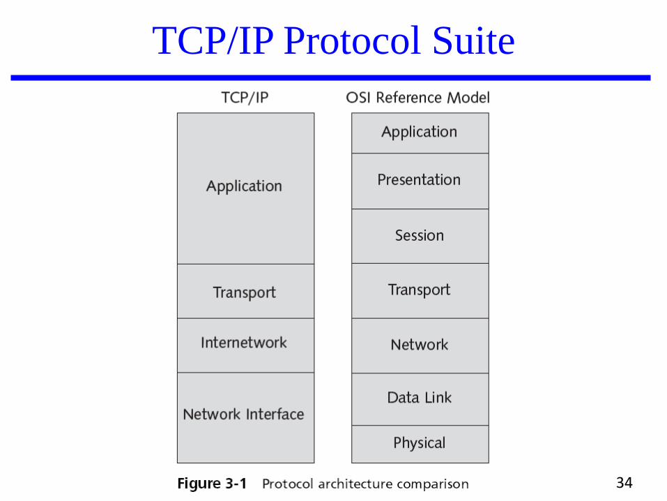
TCP/IP Protocol Suite
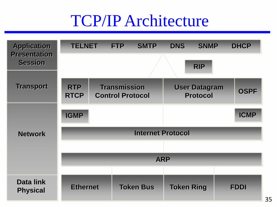
TCP/IP Architecture
Ethernet Token Bus Token Ring FDDI
Internet Protocol
ARP
TELNET FTP SMTP DNS SNMP DHCP
Data link
Physical
Network
Transport
Application
Presentation
Session
ICMP IGMP
RTP
RTCP
Transmission
Control Protocol
User Datagram
Protocol OSPF
RIP
35
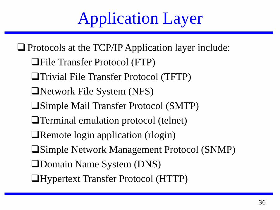
Application Layer
Protocols at the TCP/IP Application layer include:
File Transfer Protocol (FTP)
Trivial File Transfer Protocol (TFTP)
Network File System (NFS)
Simple Mail Transfer Protocol (SMTP)
Terminal emulation protocol (telnet)
Remote login application (rlogin)
Simple Network Management Protocol (SNMP)
Domain Name System (DNS)
Hypertext Transfer Protocol (HTTP)
36
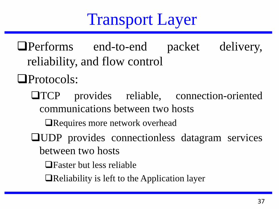
Transport Layer
Performs end-to-end packet delivery,
reliability, and flow control
Protocols:
TCP provides reliable, connection-oriented
communications between two hosts
Requires more network overhead
UDP provides connectionless datagram services
between two hosts
Faster but less reliable
Reliability is left to the Application layer
37
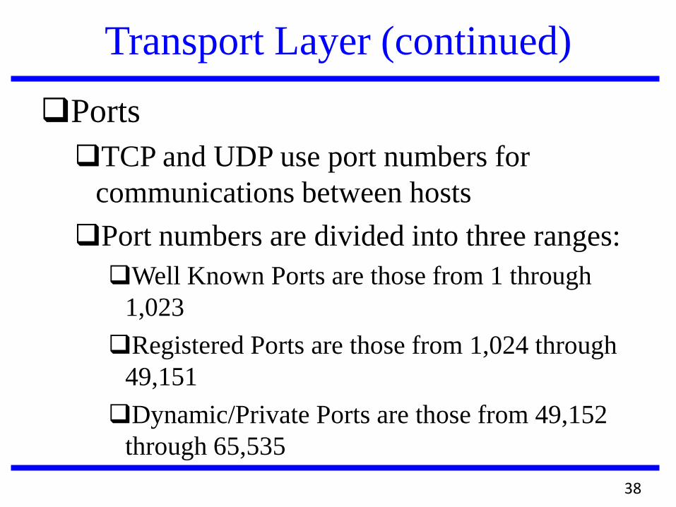
Transport Layer (continued)
Ports
TCP and UDP use port numbers for
communications between hosts
Port numbers are divided into three ranges:
Well Known Ports are those from 1 through
1,023
Registered Ports are those from 1,024 through
49,151
Dynamic/Private Ports are those from 49,152
through 65,535
38
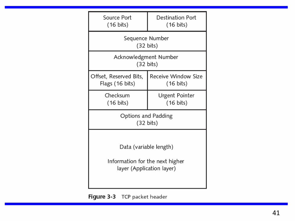
39
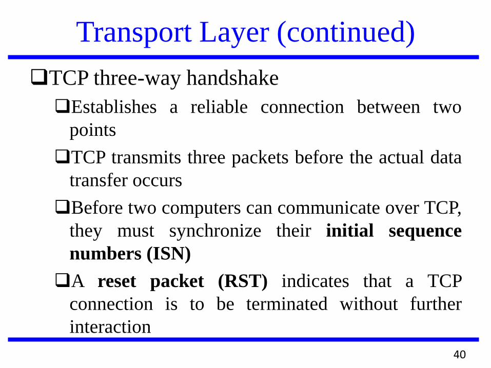
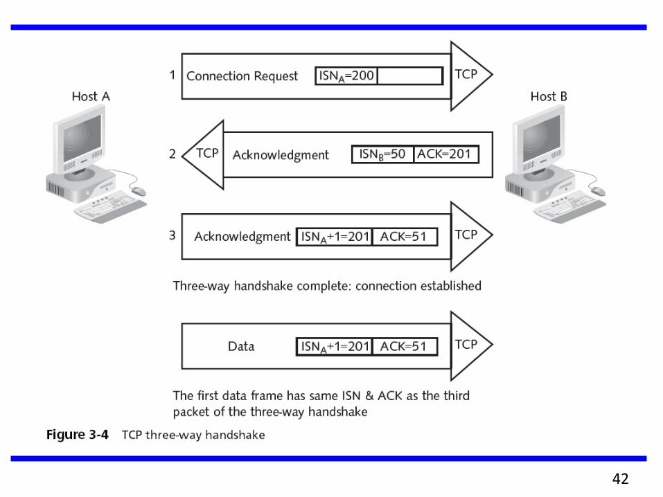
Transport Layer (continued)
TCP three-way handshake
Establishes a reliable connection between two
points
TCP transmits three packets before the actual data
transfer occurs
Before two computers can communicate over TCP,
they must synchronize their initial sequence
numbers (ISN)
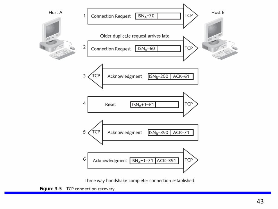
A reset packet (RST) indicates that a TCP
connection is to be terminated without further
interaction
40
41
42
43
Adaption of TCP Window
TCP sliding windows
Control the flow and efficiency of communication
Also known as windowing
A method of controlling packet flow between hosts
Allows multiple packets to be sent and affirmed with a
single acknowledgment packet
The size of the TCP window determines the
number of acknowledgments sent for a given data
transfer
Networks that perform large data transfers should
use large window sizes
44
Adaption of TCP Window
TCP sliding windows (continued)
Other flow control methods include
Buffering
Congestion avoidance
45
Internetwork Layer
Four main protocols function at this layer
Internet Protocol (IP)
Internet Control Message Protocol (ICMP)
Address Resolution Protocol (ARP)
Reverse Address Resolution Protocol (RARP)
ARP
A routed protocol
Maps IP addresses to MAC addresses
ARP tables contain the MAC and IP addresses of
other devices on the network
46
Internetwork Layer (continued)
ARP (continued)
When a computer transmits a frame to a
destination on the local network
It checks the ARP cache for an IP to MAC
address mapping for the destination node
ARP request
If a source computer cannot locate an IP to
MAC address mapping in its ARP table
It must obtain the correct mapping
47
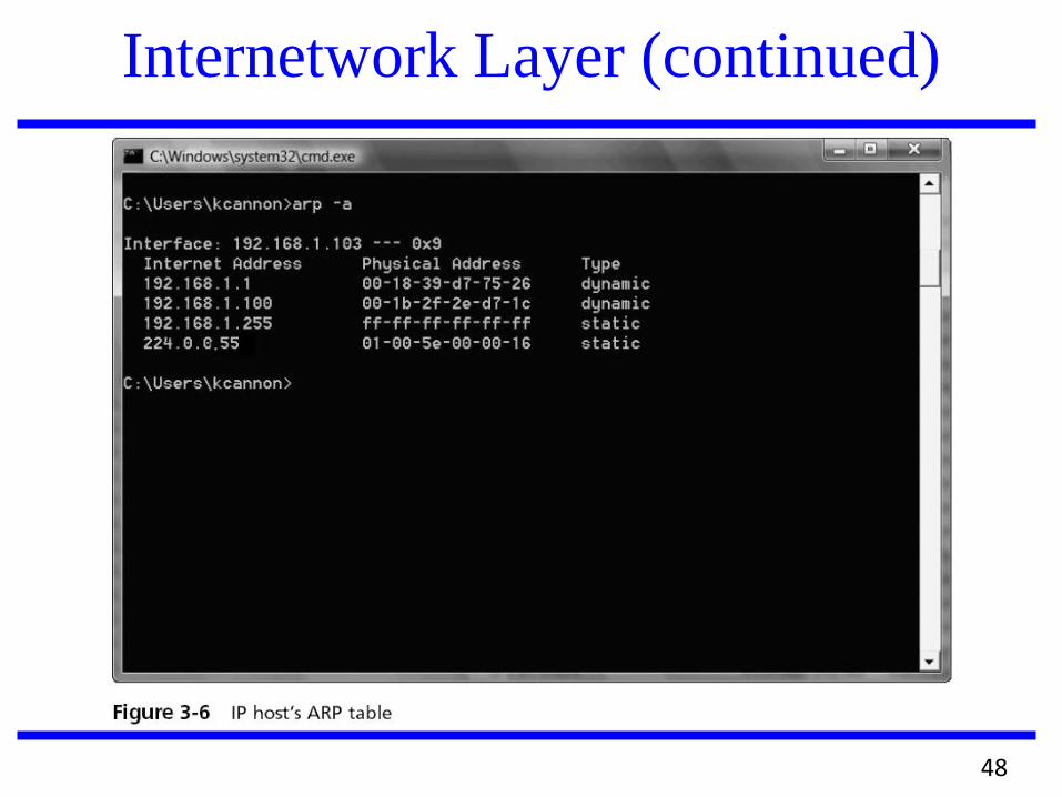
Internetwork Layer (continued)
48
Internetwork Layer (continued)
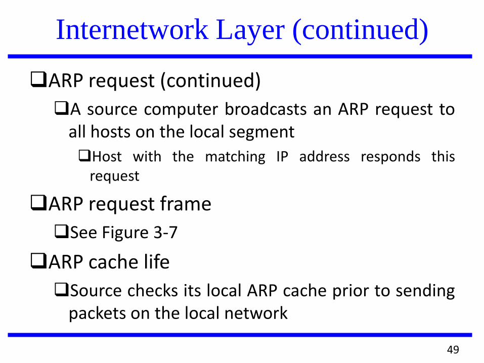
ARP request (continued)
A source computer broadcasts an ARP request to all hosts on the local segment
Host with the matching IP address responds this request
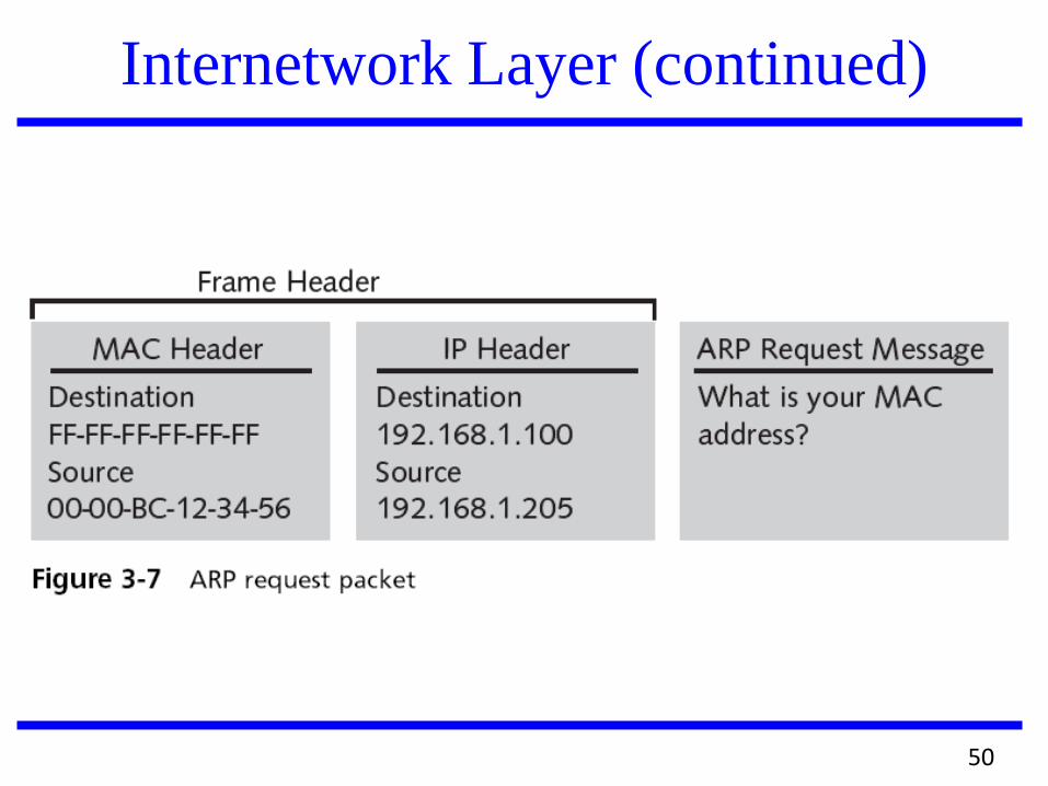
ARP request frame
See Figure 3-7
ARP cache life
Source checks its local ARP cache prior to sending packets on the local network
49
Internetwork Layer (continued)
50
Internetwork Layer (continued) ARP cache life (continued)
Important that the mappings are correct
Network devices place a timer on ARP entries
ARP tables reduce network traffic
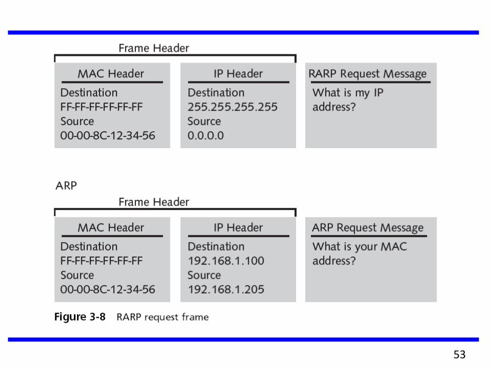
Reverse Address Resolution Protocol (RARP)
Similar to ARP
Used primarily by diskless workstations
Which have MAC addresses burned into their network
cards but no IP addresses
Client’s IP configuration is stored on a RARP
server
51
Internetwork Layer (continued) RARP request frame
See Figure 3-8
RARP client
Once a RARP client receives a RARP reply, it
configures its IP networking components
By copying its IP address configuration information
into its local RAM
ARP and RARP compared
ARP is concerned with obtaining the MAC
address of other clients
RARP obtains the IP address of the local host
52
53
Internetwork Layer (continued)
ARP and RARP compared (continued)
The local host maintains the ARP table
A RARP server maintains the RARP table
The local host uses an ARP reply to update its ARP
table and to send frames to the destination
The RARP reply is used to configure the IP protocol
on the local host
Routers and ARP
ARP requests use broadcasts
Routers filter broadcast traffic
Source must forward the frame to the router
54
Internetwork Layer (continued) ARP tables
Routers maintain ARP tables to assist in
transmitting frames from one network to another
A router uses ARP just as other hosts use ARP
Routers have multiple network interfaces and
therefore also include the port numbers of their
NICs in the ARP table
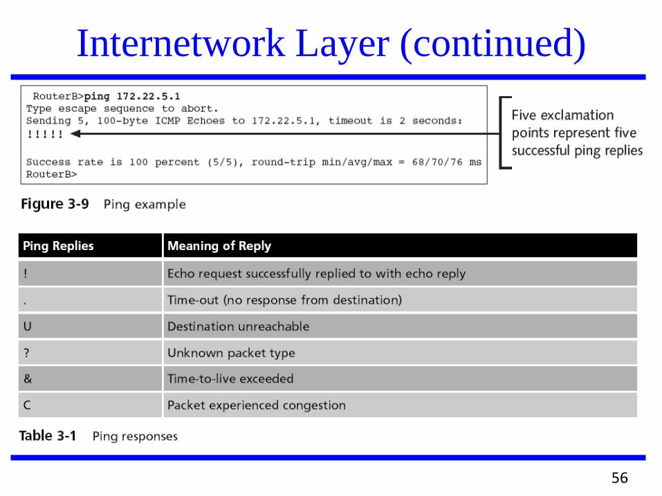
The Ping utility
Packet Internet Groper (Ping) utility verifies
connectivity between two points
Uses ICMP echo request/reply messages
55
Internetwork Layer (continued)
56
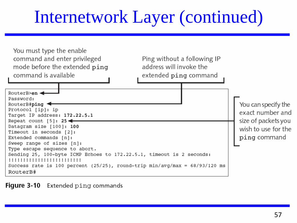
Internetwork Layer (continued)
57
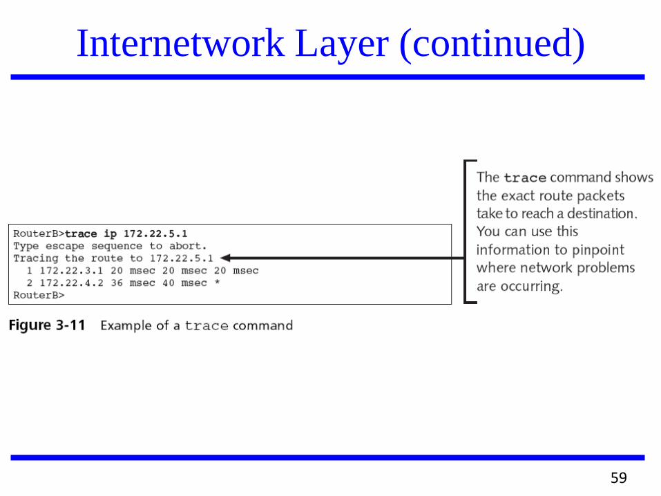
Internetwork Layer (continued)
The Trace utility
Uses ICMP echo request/reply messages
Can verify Internetwork layer (OSI-Network
layer) connectivity
Shows the exact path a packet takes from the
source to the destination
Accomplished through the use of the time-to-live
(TTL) counter
Several different malicious network attacks have
also been created using ICMP messages
Example: ICMP flood
58
59
Internetwork Layer (continued)
Network Interface Layer
Plays the same role as the Data Link and
Physical layers of the OSI model
The MAC address, network card drivers, and
specific interfaces for the network card
function at this level
No specific IP functions exist at this layer
Because the layer’s focus is on communication
with the network card and other networking
hardware
60
Traditional TCP
Assume congestion to be the primary cause for packet losses and unusual delays
Invoke congestion control and avoidance algorithms, resulting in significant degraded end-to-end performance and very high interactive delays
61
TCP in Mobile Wireless Networks
Communication characterized by
sporadic high bit-error rates (10-4 to
10-6)
disconnections
intermittent connectivity due to
handoffs
low bandwidth
62
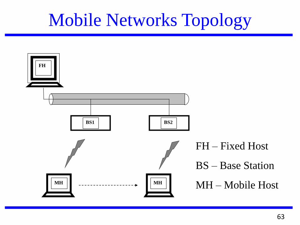
Mobile Networks Topology
FH
BS1 BS2
MH MH
FH – Fixed Host
BS – Base Station
MH – Mobile Host
63
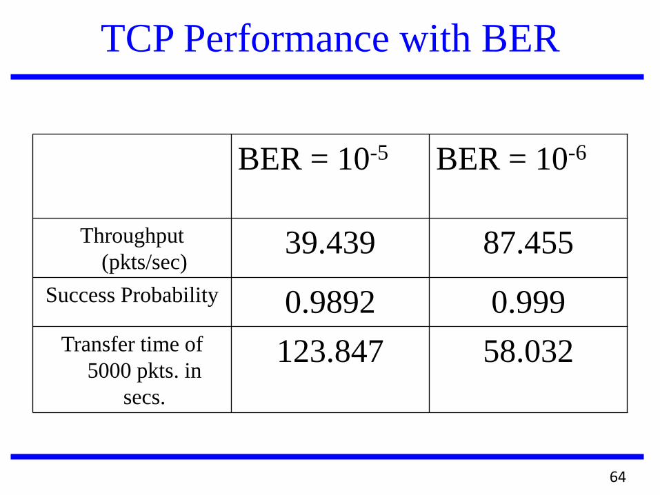
TCP Performance with BER
BER = 10-5 BER = 10-6
Throughput
(pkts/sec) 39.439 87.455
Success Probability 0.9892 0.999
Transfer time of
5000 pkts. in
secs.
123.847 58.032
64
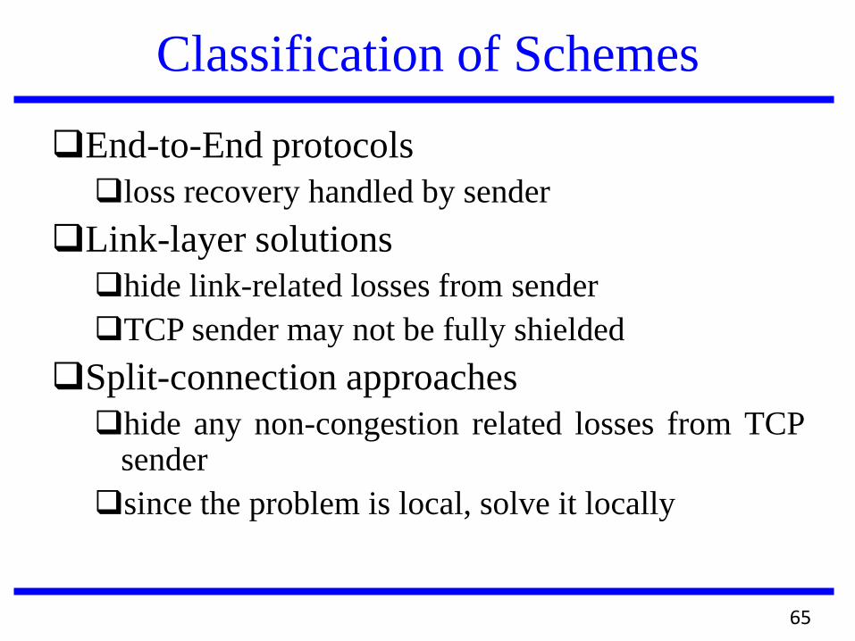
Classification of Schemes
End-to-End protocols
loss recovery handled by sender
Link-layer solutions
hide link-related losses from sender
TCP sender may not be fully shielded
Split-connection approaches
hide any non-congestion related losses from TCP sender
since the problem is local, solve it locally
65
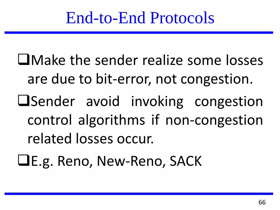
End-to-End Protocols
Make the sender realize some losses are due to bit-error, not congestion.
Sender avoid invoking congestion control algorithms if non-congestion related losses occur.
E.g. Reno, New-Reno, SACK
66
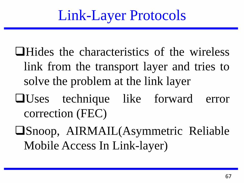
Link-Layer Protocols
Hides the characteristics of the wireless
link from the transport layer and tries to
solve the problem at the link layer
Uses technique like forward error
correction (FEC)
Snoop, AIRMAIL(Asymmetric Reliable
Mobile Access In Link-layer)
67
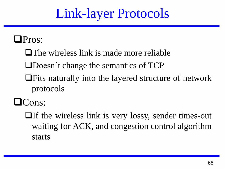
Link-layer Protocols
Pros:
The wireless link is made more reliable
Doesn’t change the semantics of TCP
Fits naturally into the layered structure of network
protocols
Cons:
If the wireless link is very lossy, sender times-out
waiting for ACK, and congestion control algorithm
starts
68
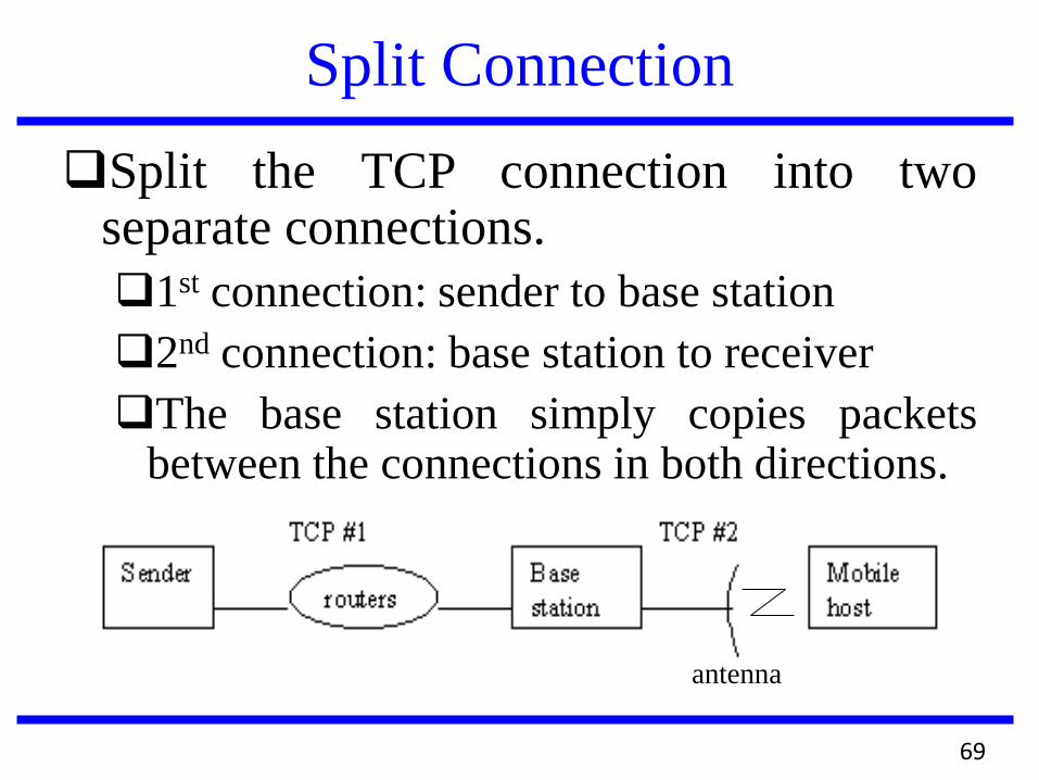
Split Connection
Split the TCP connection into two separate connections.
1st connection: sender to base station
2nd connection: base station to receiver
The base station simply copies packets between the connections in both directions.
antenna
69
Split Connection
Pros:
Sender shielded from wireless link.
Better throughput can be achieved by fine
tuning the wireless protocol link.
Cons:
Violates the semantics of TCP
Extra copying at the Base station.
70
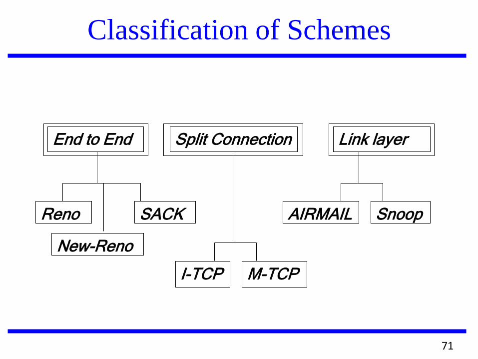
Classification of Schemes
End to End Split Connection Link layer
Reno
New-Reno
SACK
I-TCP M-TCP
AIRMAIL Snoop
71
Improving TCP/IP Performance
Over Wireless Networks
72
Snoop-TCP
A (snoop) layer is added to the routing code at BS which keep track of packets in both directions
Packets meant to MH are cached at BS, and if needed, retransmitted in the wireless link
BS suppress DUPACKs sent from MH to FH
BS use shorter local timer for local timeout
73
Snoop-TCP
Changes are restricted to BS and
optionally to MH as well
E2E TCP semantics is preserved
74
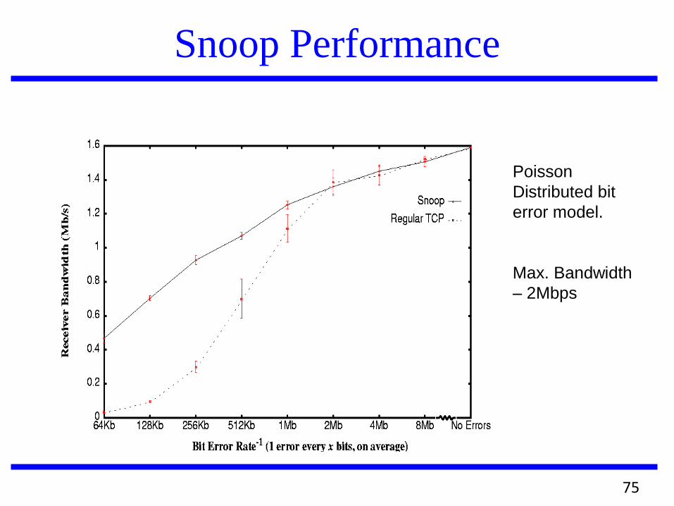
Snoop Performance
Poisson
Distributed bit
error model.
Max. Bandwidth
– 2Mbps
75
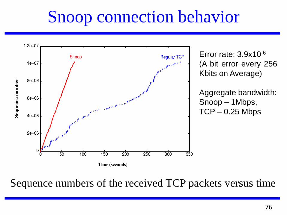
Snoop connection behavior
Error rate: 3.9x10⁻⁶
(A bit error every 256
Kbits on Average)
Aggregate bandwidth:
Snoop – 1Mbps,
TCP – 0.25 Mbps
Sequence numbers of the received TCP packets versus time
76
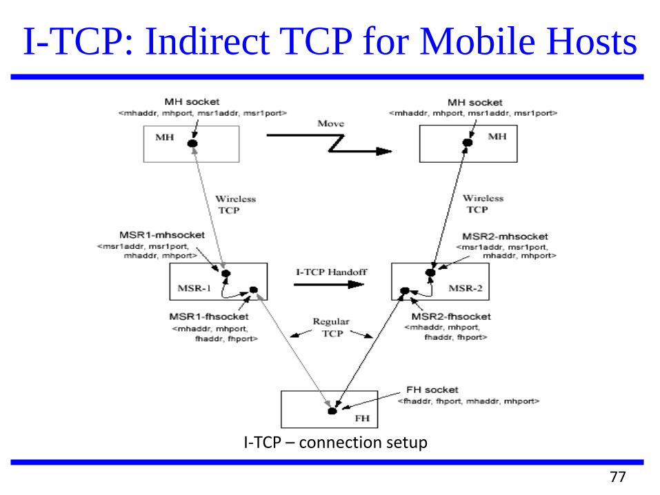
I-TCP – connection setup
I-TCP: Indirect TCP for Mobile Hosts
77
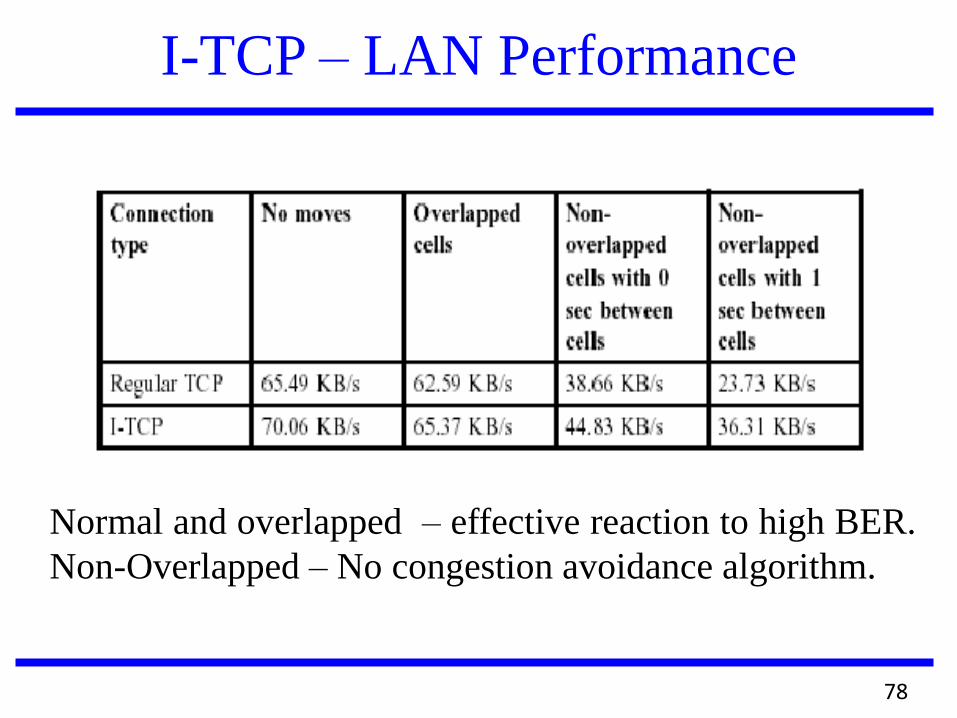
I-TCP – LAN Performance
Normal and overlapped – effective reaction to high BER.
Non-Overlapped – No congestion avoidance algorithm.
78
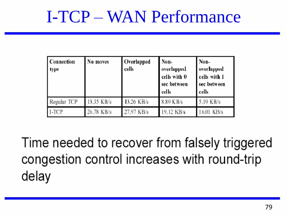
I-TCP – WAN Performance
79
I-TCP
Disadvantages
End-to-end semantics is not followed
MSR sends an ack to the correspondent but
loses the packet to the mobile host
Copying overhead at MSR
Conclusion
I-TCP particularly suited for applications
which are throughput intensive
80
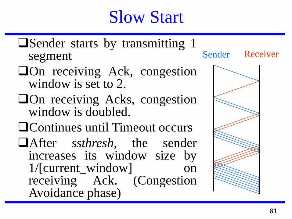
Slow Start
Sender starts by transmitting 1 segment
On receiving Ack, congestion window is set to 2.
On receiving Acks, congestion window is doubled.
Continues until Timeout occurs
After ssthresh, the sender increases its window size by 1/[current_window] on receiving Ack. (Congestion Avoidance phase)
Sender Receiver
81
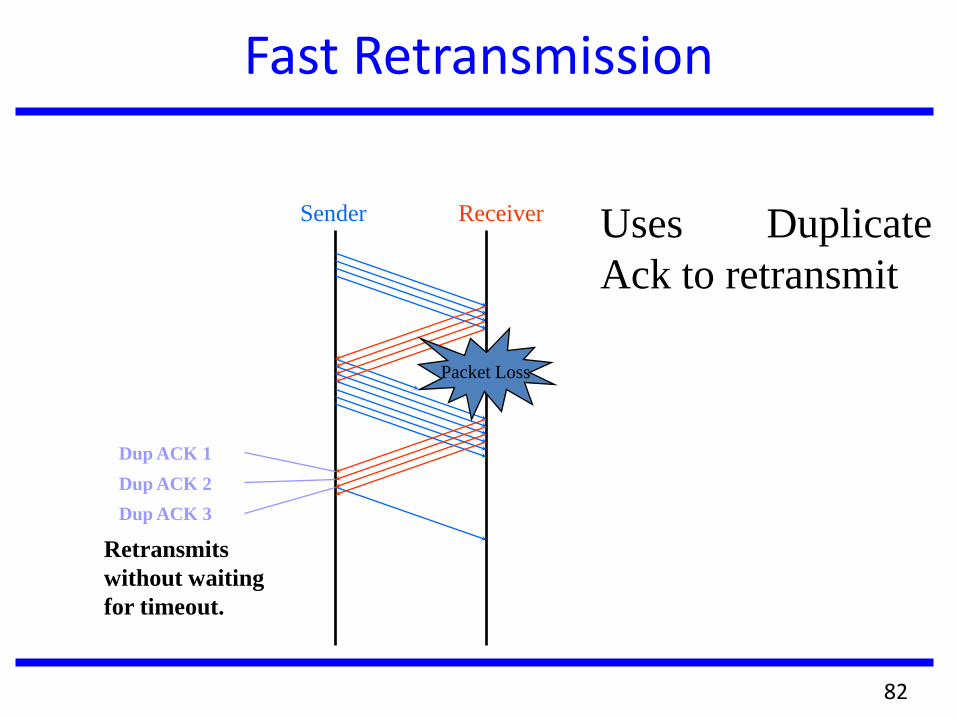
Fast Retransmission
Sender Receiver
Dup ACK 1
Dup ACK 2
Dup ACK 3
Retransmits
without waiting
for timeout.
Packet Loss
Uses Duplicate
Ack to retransmit
82
Fast Recovery
After Fast retransmit, perform congestion
avoidance instead of slow start.
Why?
Duplicate ACK indicates that there are still
data flowing between the two ends →
Network resources are still available.
TCP does not want to reduce the flow
abruptly by going into slow start.
83
End to End Protocols
Tahoe: Original TCP Slow start, Congestion avoidance, Fast retransmit
Reno: TCP Tahoe + Fast Recovery
Significant Improvement - single packet loss.
Suffers when multiple packets are dropped.
New-Reno: Reno + Stay in Fast Recovery
The first non-duplicate ACK but not the expected one.
SACK: Reno + SACK option When multiple packets are dropped
84
Packet Loss Scenario
Tahoe
Fast Retransmission
ssthresh = 0.5 x current window size
congestion window = 1
Reno, New-Reno and SACK
Fast Retransmission
Fast Recovery
congestion window = 0.5 x current window size + 3 x segment size
Increase window size by 1 on receiving a dup ACK
85

Questions ?