Embed Size (px)
Citation preview
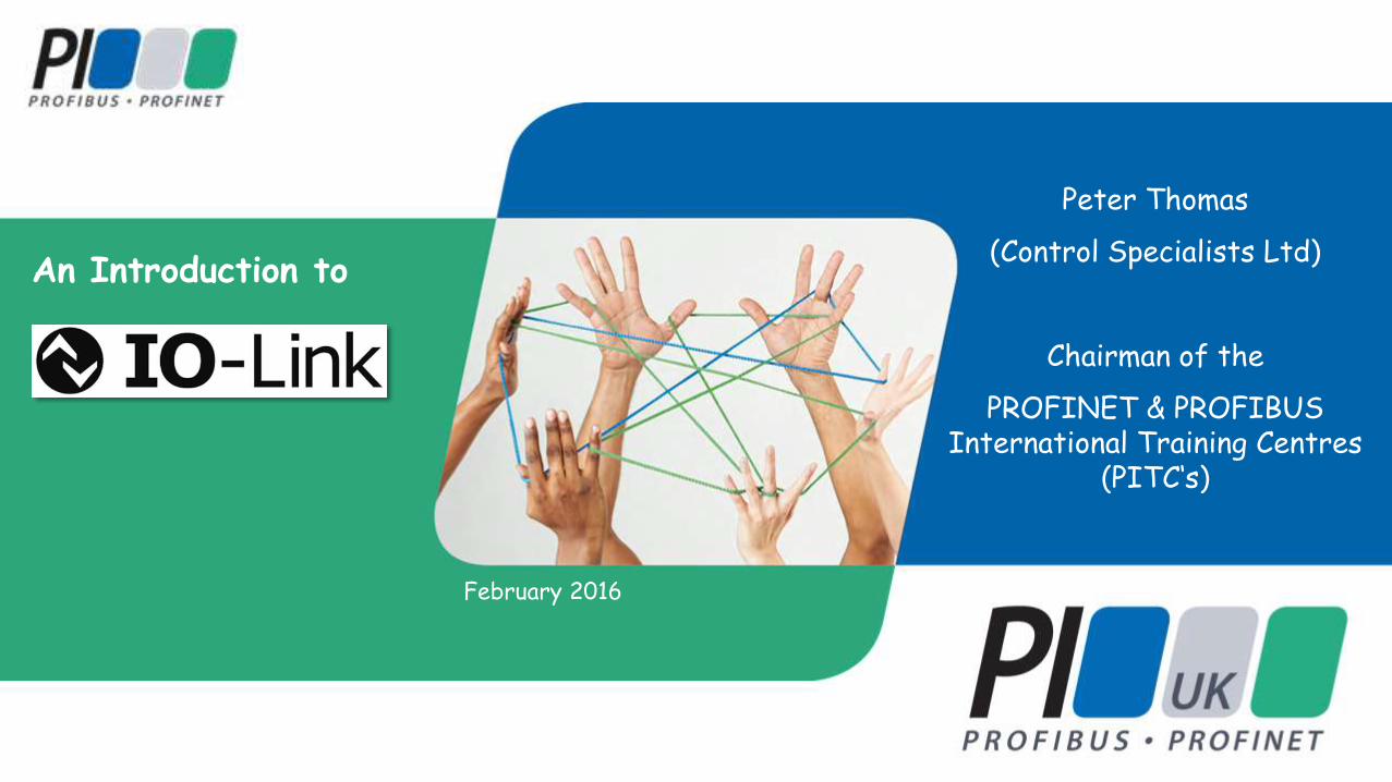
An Introduction to
February 2016
Peter Thomas
(Control Specialists Ltd)
Chairman of the
PROFINET & PROFIBUS International Training Centres
(PITC‘s)
IO-Link – What is it? 2
• IO-Link is the first standardised IO technology worldwide (IEC 61131-9) for the communication with sensors and also actuators.
• It is typically used in an automation environment below the I/O level for individual linking of field devices
• It uses point-to-point communication based on the long established 3-wire sensor and actuator connection without additional requirements regarding cabling.
• IO-Link is not a fieldbus, nor is it a replacement for AS-i. It is however evidence of the further development of the existing, tried-and-tested connection technology for sensors and actuators.
• Since 2010, IO-Link has been incorporated within the PROFIBUS & PROFINET User Organisation (PNO)
IO-Link – Benefits 3
• IEC 61131-9 compliance means that IO-Link devices can be integrated using the same methods used to integrate PROFIBUS and PROFINET devices.
• Simple, standardised wiring and significantly reduced variety of interfaces for sensors and actuators.
• Standardised interface for the configuration of all IO-Link devices irrespective of their complexity.
• Faster commissioning.
• Access to diagnostic data and device information as well as process data.
• Sensors with and without an IO-Link interface can operate together via the same IO-Link Master.
• Dynamic changing of device parameters by PLC (or HMI) during normal plant operation.
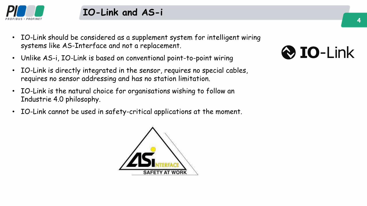
IO-Link and AS-i 4
• IO-Link should be considered as a supplement system for intelligent wiring systems like AS-Interface and not a replacement.
• Unlike AS-i, IO-Link is based on conventional point-to-point wiring
• IO-Link is directly integrated in the sensor, requires no special cables, requires no sensor addressing and has no station limitation.
• IO-Link is the natural choice for organisations wishing to follow an Industrie 4.0 philosophy.
• IO-Link cannot be used in safety-critical applications at the moment.
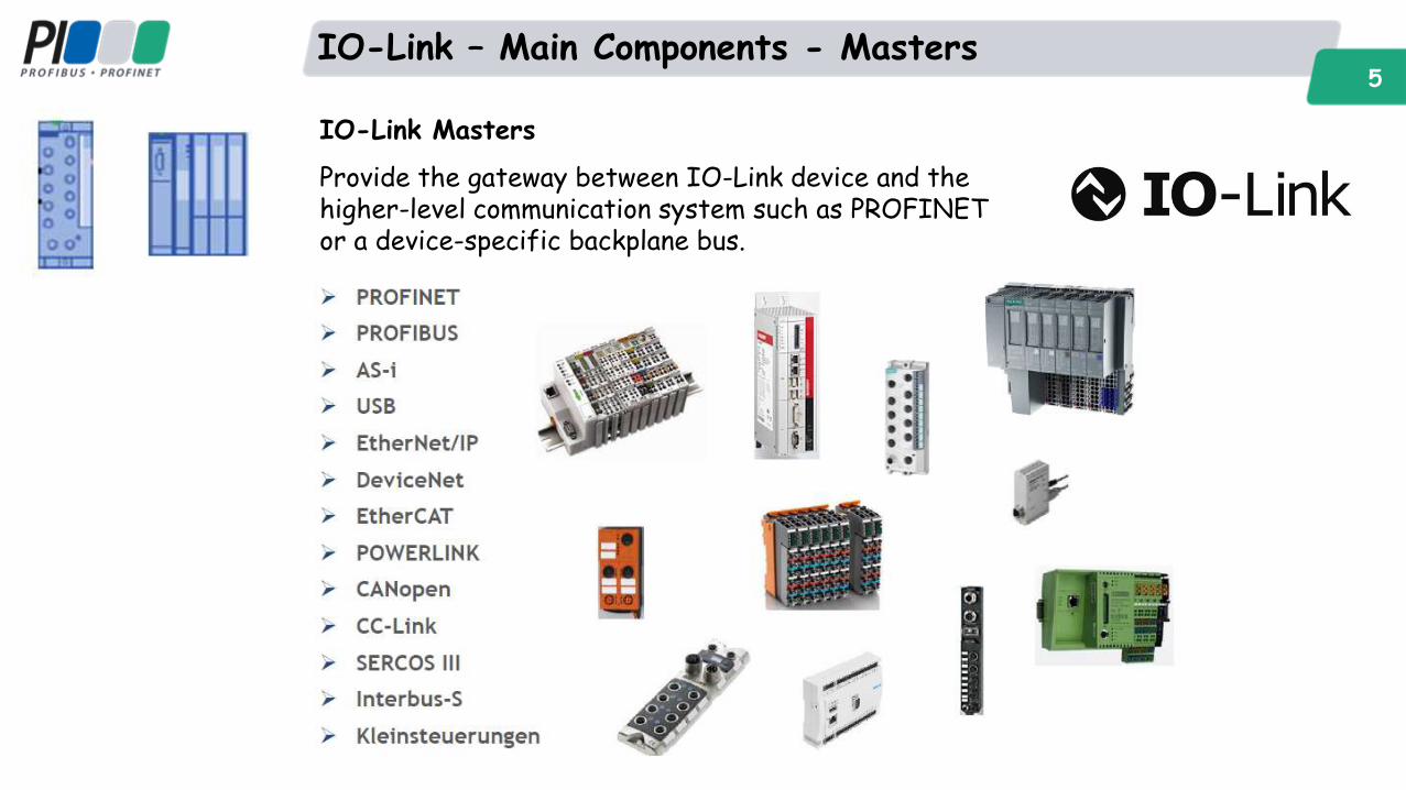
IO-Link – Main Components - Masters 5
IO-Link Masters
Provide the gateway between IO-Link device and the higher-level communication system such as PROFINET or a device-specific backplane bus.
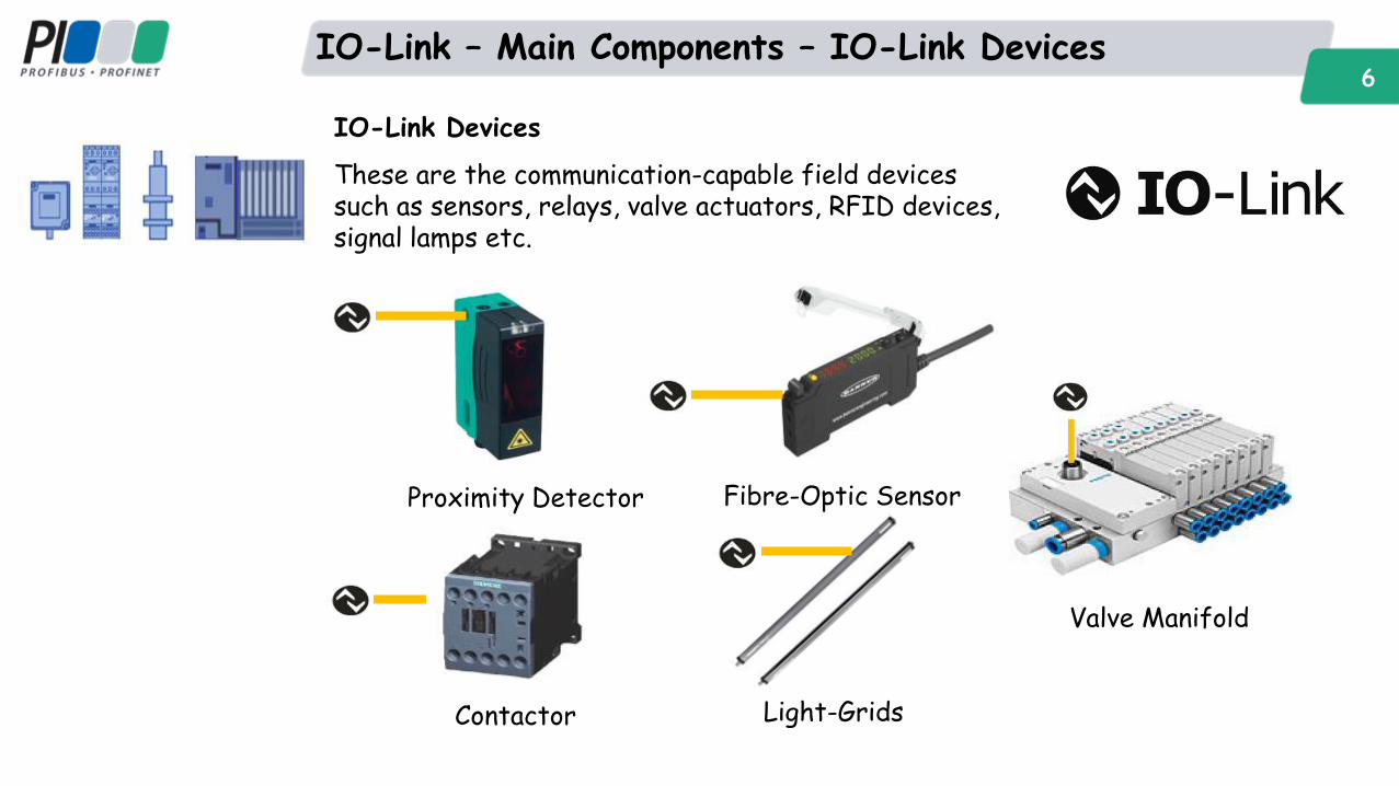
IO-Link – Main Components – IO-Link Devices 6
IO-Link Devices
These are the communication-capable field devices such as sensors, relays, valve actuators, RFID devices, signal lamps etc.
Proximity Detector Fibre-Optic Sensor
Light-Grids
Valve Manifold
Contactor
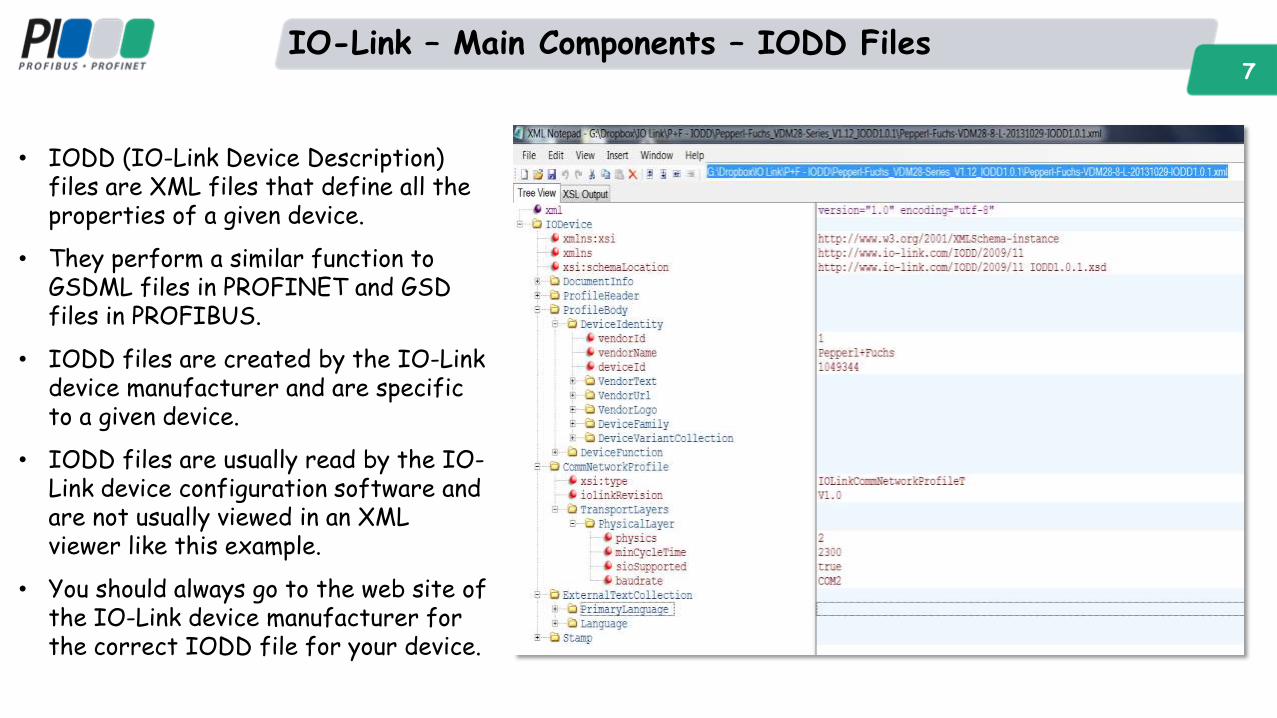
IO-Link – Main Components – IODD Files 7
• IODD (IO-Link Device Description) files are XML files that define all the properties of a given device.
• They perform a similar function to GSDML files in PROFINET and GSD files in PROFIBUS.
• IODD files are created by the IO-Link device manufacturer and are specific to a given device.
• IODD files are usually read by the IO-Link device configuration software and are not usually viewed in an XML viewer like this example.
• You should always go to the web site of the IO-Link device manufacturer for the correct IODD file for your device.
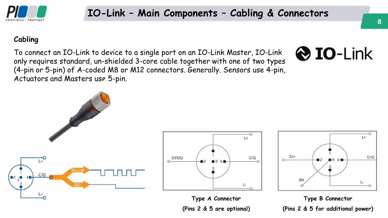
IO-Link – Main Components – Cabling & Connectors 8
Cabling
To connect an IO-Link to device to a single port on an IO-Link Master, IO-Link only requires standard, un-shielded 3-core cable together with one of two types (4-pin or 5-pin) of A-coded M8 or M12 connectors. Generally. Sensors use 4-pin, Actuators and Masters use 5-pin.
Type A Connector
(Pins 2 & 5 are optional)
Type B Connector
(Pins 2 & 5 for additional power)
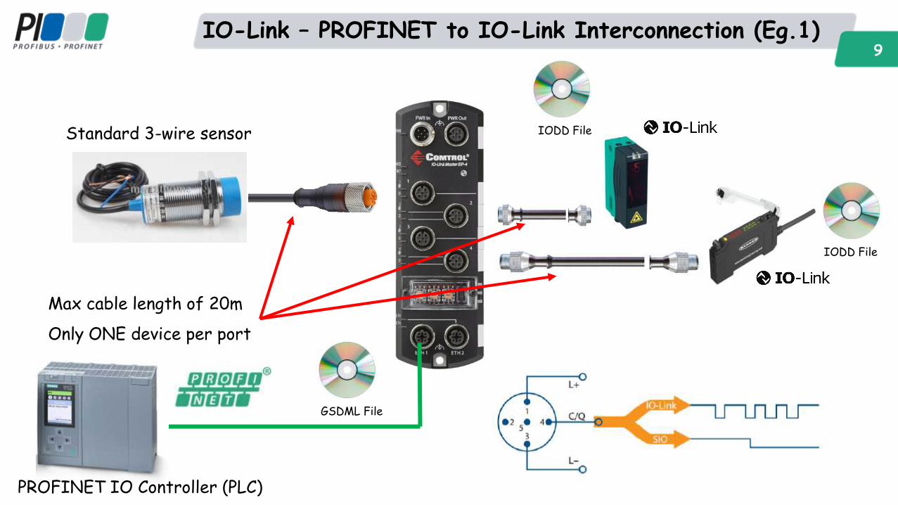
IO-Link – PROFINET to IO-Link Interconnection (Eg.1) 9
Standard 3-wire sensor
Max cable length of 20m
Only ONE device per port
IODD File
IODD File
GSDML File
PROFINET IO Controller (PLC)
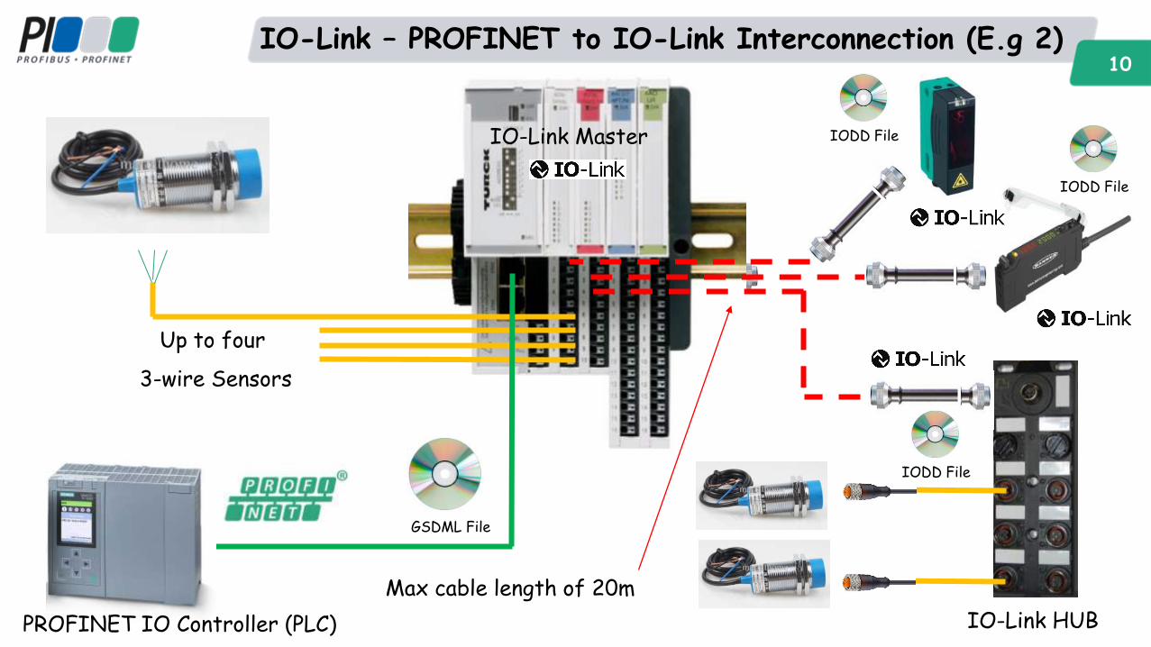
IO-Link – PROFINET to IO-Link Interconnection (E.g 2) 10
Up to four
3-wire Sensors
IO-Link HUB
IO-Link Master IODD File
GSDML File
IODD File
IODD File
PROFINET IO Controller (PLC)
Max cable length of 20m
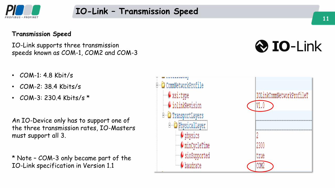
IO-Link – Transmission Speed 11
Transmission Speed
IO-Link supports three transmission speeds known as COM-1, COM2 and COM-3
• COM-1: 4.8 Kbit/s
• COM-2: 38.4 Kbits/s
• COM-3: 230.4 Kbits/s *
An IO-Device only has to support one of the three transmission rates, IO-Masters must support all 3.
* Note – COM-3 only became part of the IO-Link specification in Version 1.1
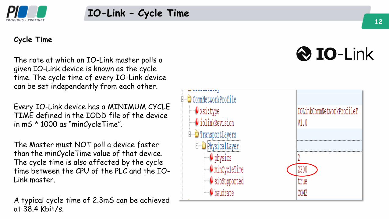
IO-Link – Cycle Time 12
Cycle Time
The rate at which an IO-Link master polls a given IO-Link device is known as the cycle time. The cycle time of every IO-Link device can be set independently from each other.
Every IO-Link device has a MINIMUM CYCLE TIME defined in the IODD file of the device in mS * 1000 as “minCycleTime”.
The Master must NOT poll a device faster than the minCycleTime value of that device. The cycle time is also affected by the cycle time between the CPU of the PLC and the IO-Link master.
A typical cycle time of 2.3mS can be achieved at 38.4 Kbit/s.
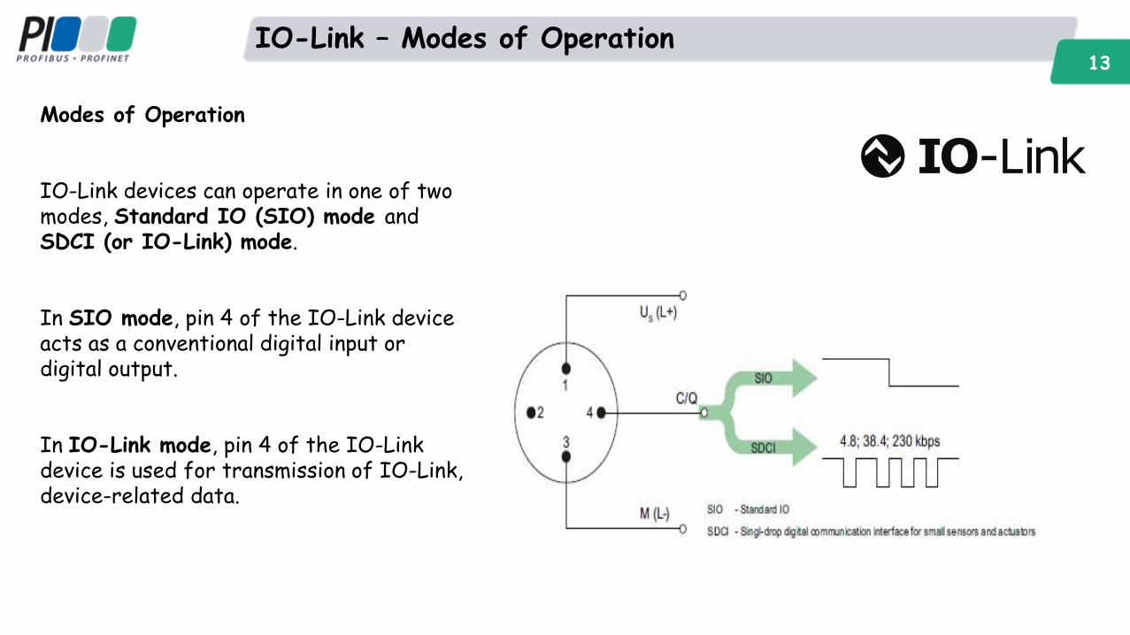
IO-Link – Modes of Operation 13
Modes of Operation
IO-Link devices can operate in one of two modes, Standard IO (SIO) mode and SDCI (or IO-Link) mode.
In SIO mode, pin 4 of the IO-Link device acts as a conventional digital input or digital output.
In IO-Link mode, pin 4 of the IO-Link device is used for transmission of IO-Link, device-related data.
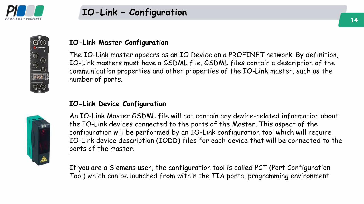
IO-Link – Configuration 14
IO-Link Master Configuration
The IO-Link master appears as an IO Device on a PROFINET network. By definition, IO-Link masters must have a GSDML file. GSDML files contain a description of the communication properties and other properties of the IO-Link master, such as the number of ports.
IO-Link Device Configuration
An IO-Link Master GSDML file will not contain any device-related information about the IO-Link devices connected to the ports of the Master. This aspect of the configuration will be performed by an IO-Link configuration tool which will require IO-Link device description (IODD) files for each device that will be connected to the ports of the master.
If you are a Siemens user, the configuration tool is called PCT (Port Configuration Tool) which can be launched from within the TIA portal programming environment
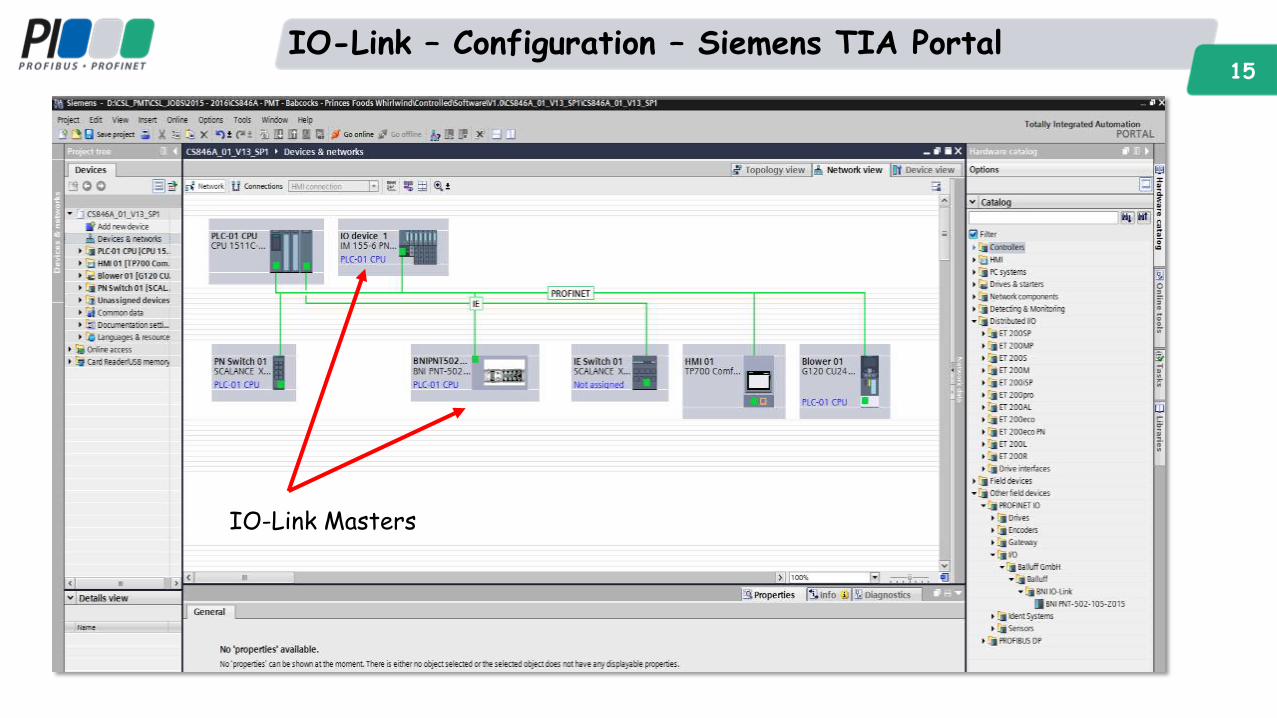
IO-Link – Configuration – Siemens TIA Portal 15
IO-Link Masters
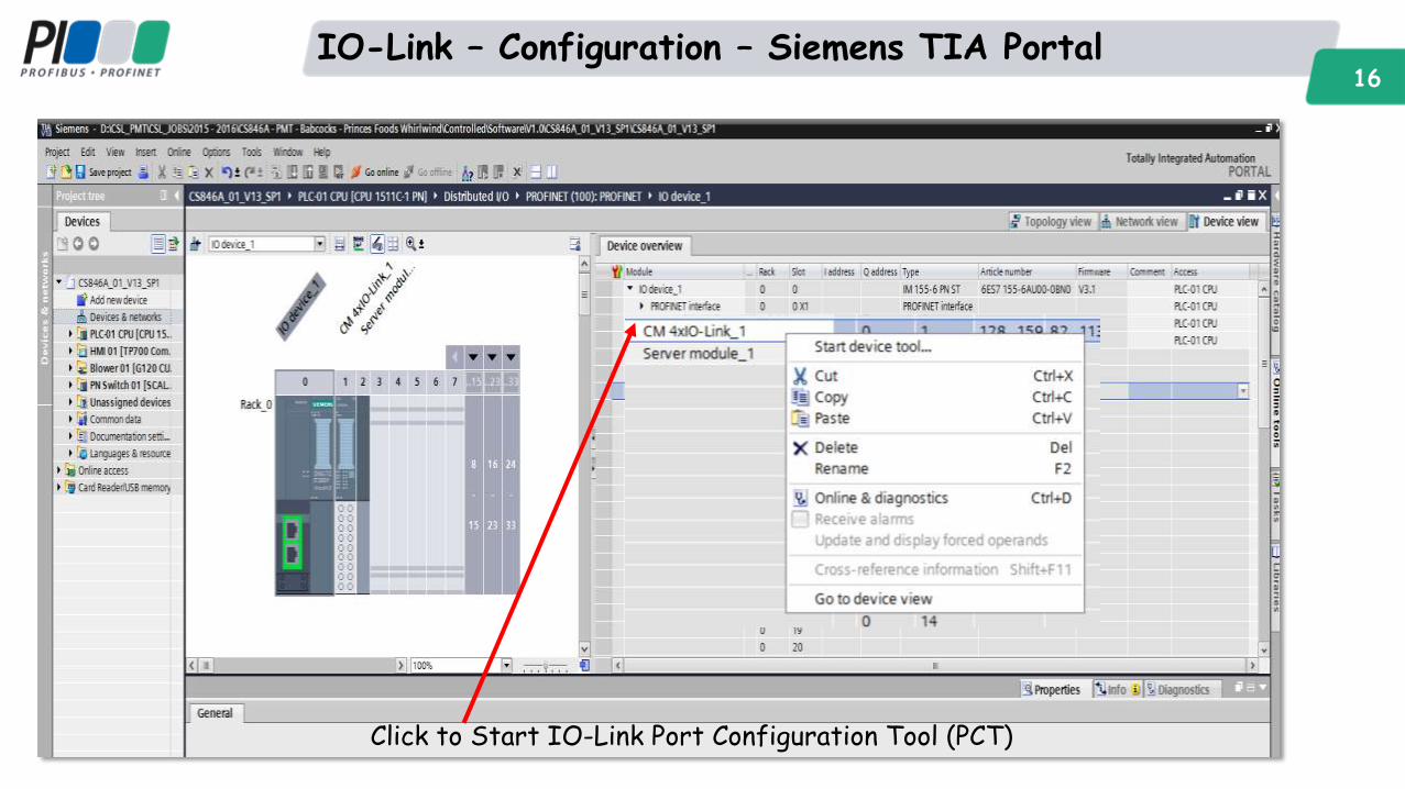
IO-Link – Configuration – Siemens TIA Portal 16
Click to Start IO-Link Port Configuration Tool (PCT)
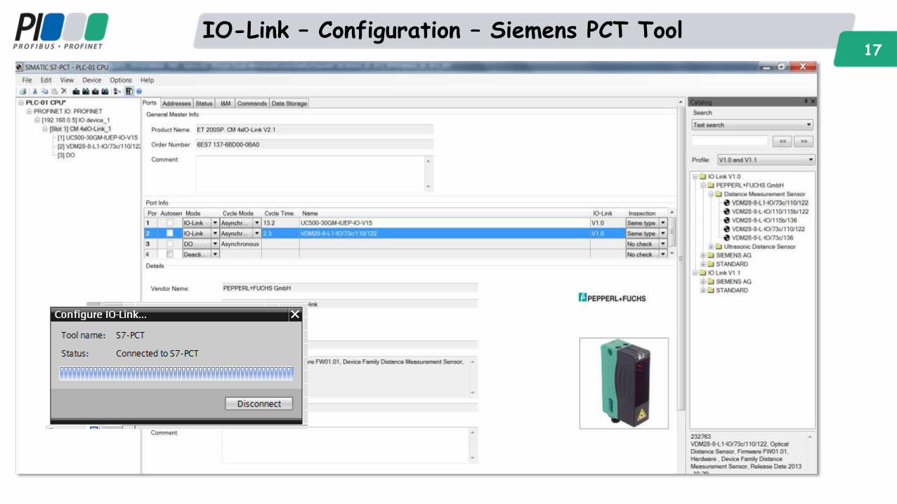
IO-Link – Configuration – Siemens PCT Tool 17
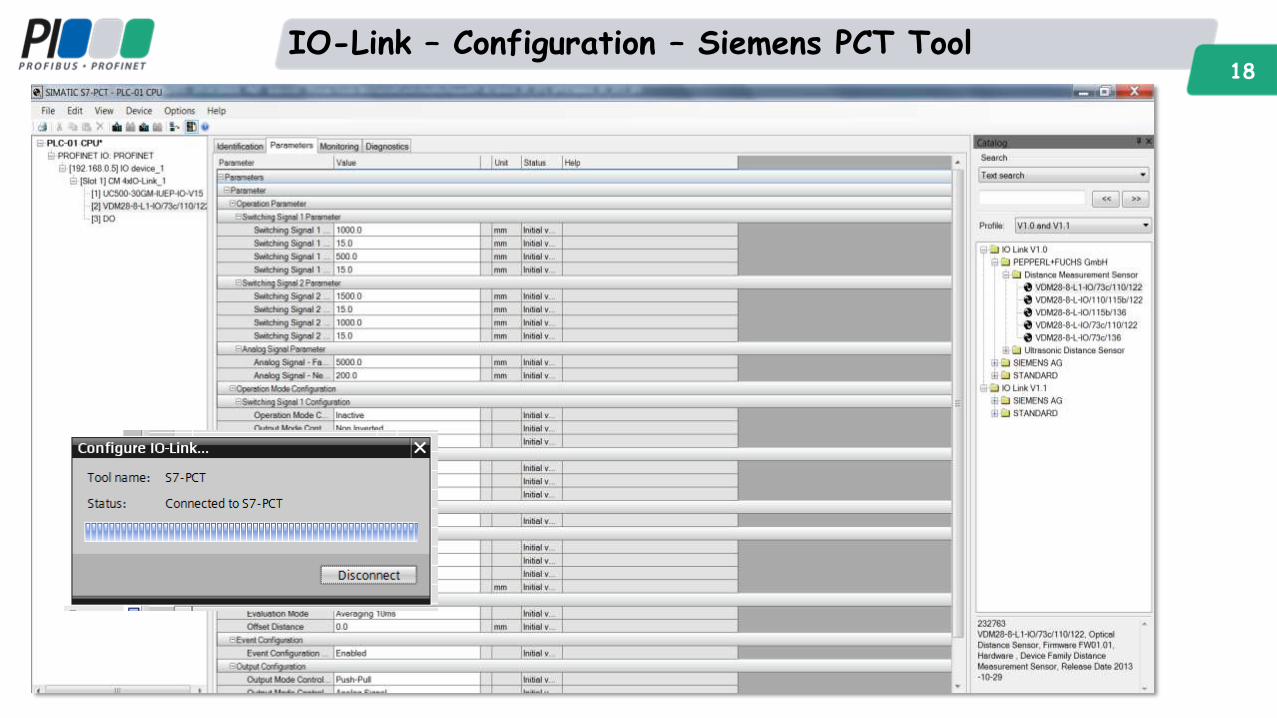
IO-Link – Configuration – Siemens PCT Tool 18
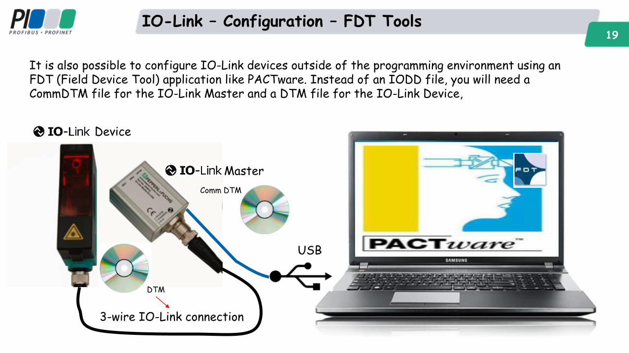
IO-Link – Configuration – FDT Tools 19
It is also possible to configure IO-Link devices outside of the programming environment using an FDT (Field Device Tool) application like PACTware. Instead of an IODD file, you will need a CommDTM file for the IO-Link Master and a DTM file for the IO-Link Device,
3-wire IO-Link connection
USB
Master
Device
DTM
Comm DTM
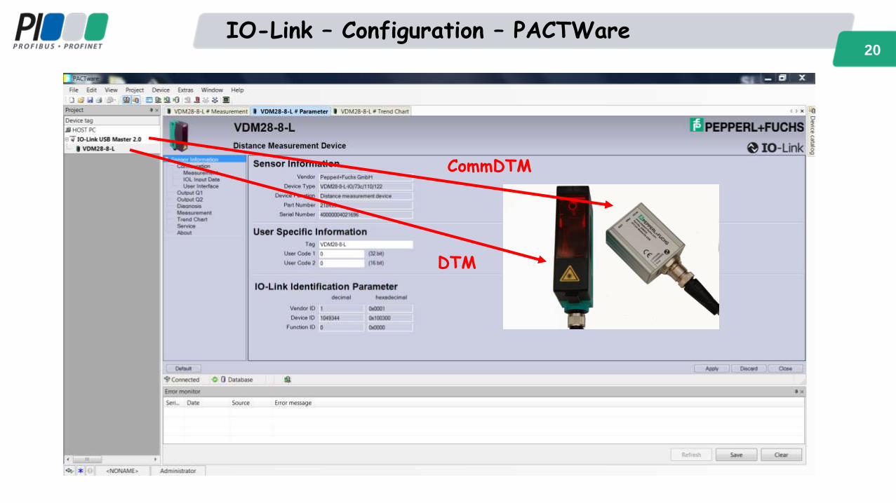
IO-Link – Configuration – PACTWare 20
CommDTM
DTM
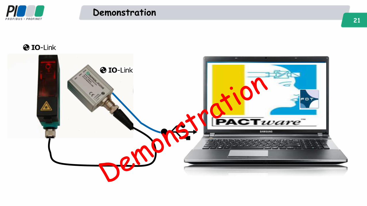
21 Demonstration
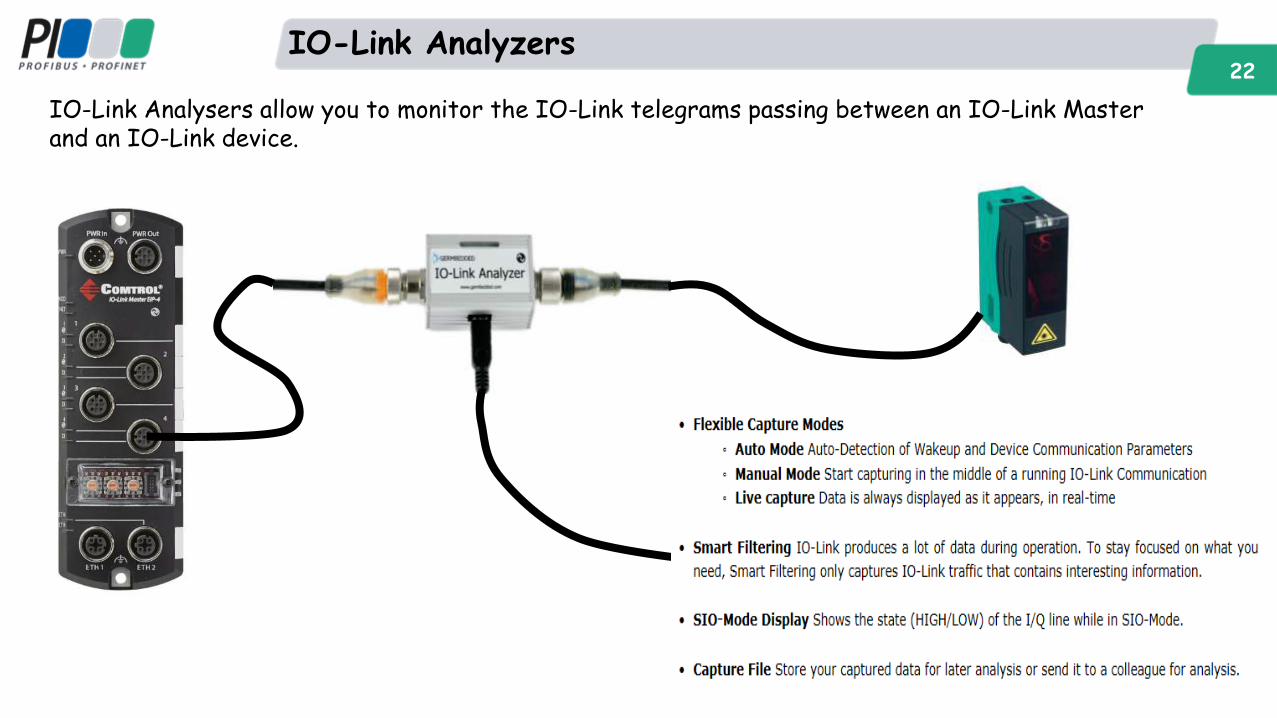
IO-Link Analyzers 22
IO-Link Analysers allow you to monitor the IO-Link telegrams passing between an IO-Link Master and an IO-Link device.
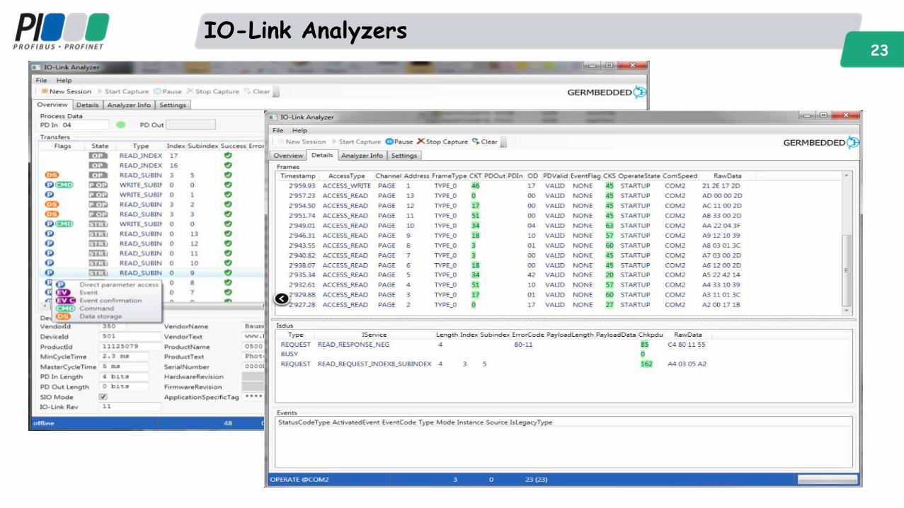
IO-Link Analyzers 23
PROFINET – Questions?