Embed Size (px)
Citation preview

1
By:Ritula Thakur
NITTTR, Chandigarh
2
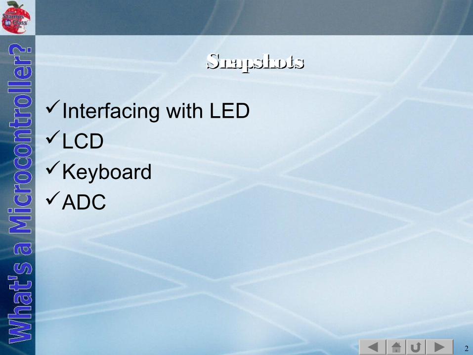
SnapshotsSnapshots
Interfacing with LEDLCDKeyboardADC

3
4
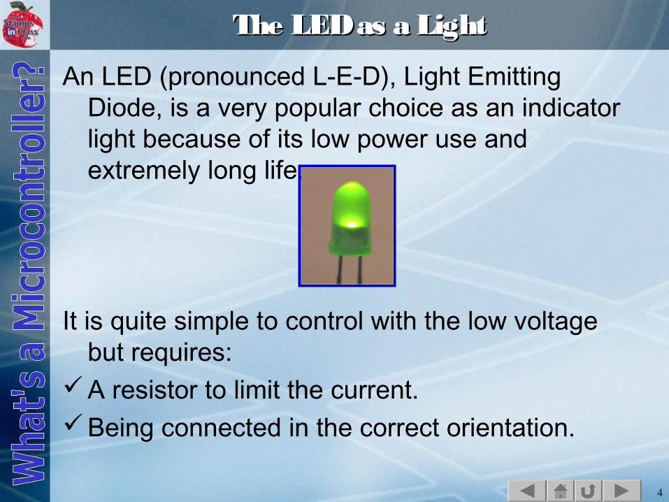
The LED as a LightThe LED as a Light
An LED (pronounced L-E-D), Light Emitting Diode, is a very popular choice as an indicator light because of its low power use and extremely long life.
It is quite simple to control with the low voltage but requires:
A resistor to limit the current.Being connected in the correct orientation.
5
Voltage and CurrentVoltage and Current
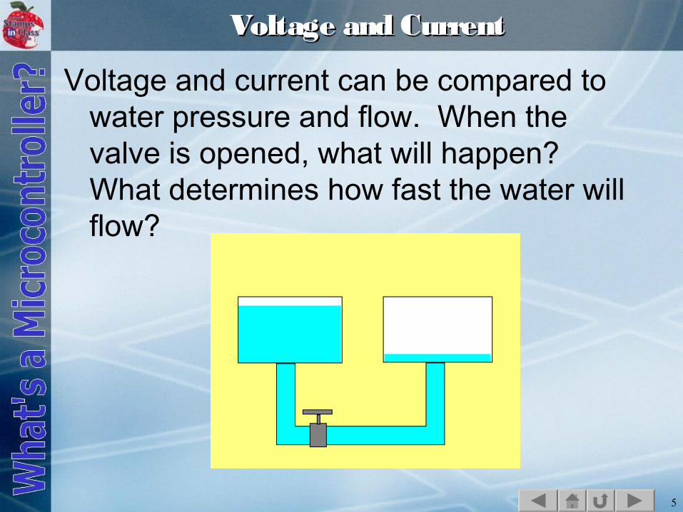
Voltage and current can be compared to water pressure and flow. When the valve is opened, what will happen? What determines how fast the water will flow?
6
Of course water will flow from the fuller tank because it has greater pressure than the empty tank.
The flow rate is dependent on:The difference in pressure between the two
tanks.The amount of restriction to flow in the pipe
and valve.
The water that flows from your facet is dependent on the height of your town's water tank, the size of the pipes, and how far you open the faucet.
7
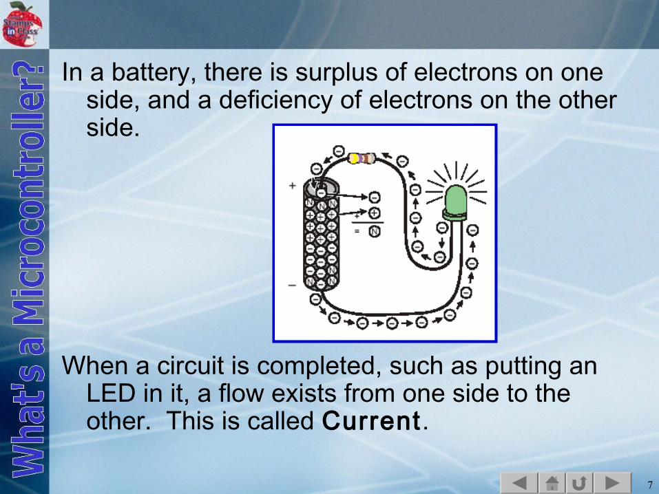
In a battery, there is surplus of electrons on one side, and a deficiency of electrons on the other side.
When a circuit is completed, such as putting an LED in it, a flow exists from one side to the other. This is called Current.
8
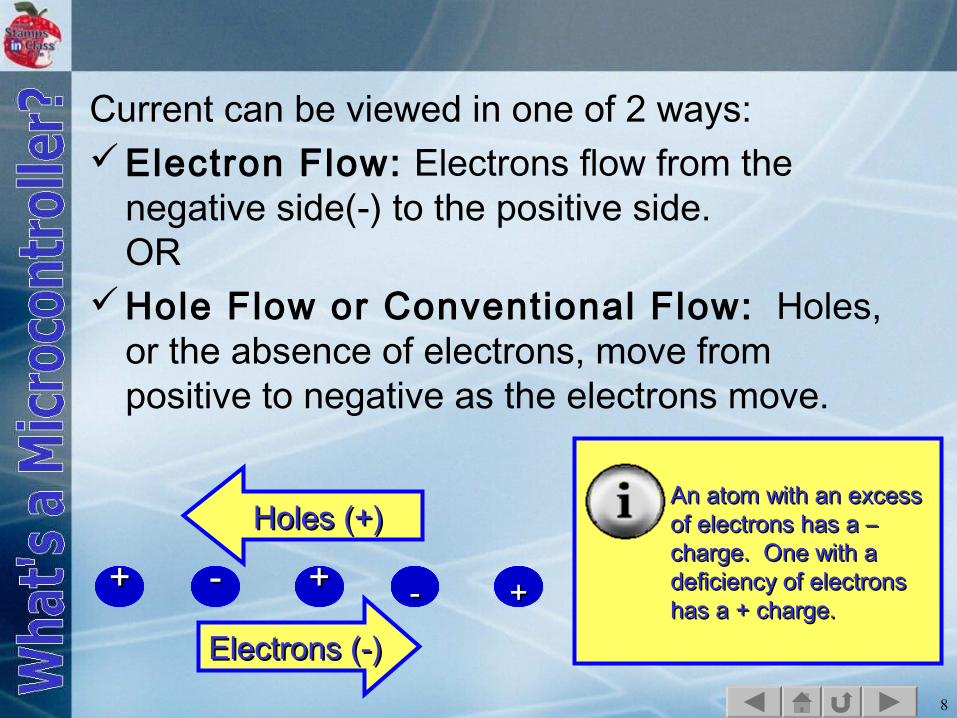
Current can be viewed in one of 2 ways:Electron Flow: Electrons flow from the
negative side(-) to the positive side.OR
Hole Flow or Conventional Flow: Holes, or the absence of electrons, move from positive to negative as the electrons move.
++++-- -- -- ++---- -- ++ --++-- ++ -- ++--++ -- ++
Electrons (-)Electrons (-)
Holes (+)Holes (+)An atom with an excess An atom with an excess of electrons has a – of electrons has a – charge. One with a charge. One with a deficiency of electrons deficiency of electrons has a + charge.has a + charge.
9
Which version of flow is used doesn't matter. How much flows does. Just as with the water tanks:
The greater the pressure, or the difference in potential (Voltage), the greater the amount of current that can flow in a unit time (Amperes).
The greater the restriction to flow (Ohms), the lower the amount current that can flow.
10
Ohm's LawOhm's Law
Ohms Law states: The amount of current (I) that will flow is proportional to the voltage applied (V), and inversely proportional to the resistance (R) of the circuit.
I = V/R
As Resistance increases, current decreases.
11
LEDs have minimal resistance to current flow. A 5 volt source can destroy an LED if current is not restricted. From Ohm's Law, if R is 1 Ω, how much current will try to flow? An LED drops approximately 1.4V, leaving 3.6V.
I = (5V-1.4V)/1Ω = 3.6 A
The maximum current a typical LED can handle is around 30mA, or .030 A.

12
13
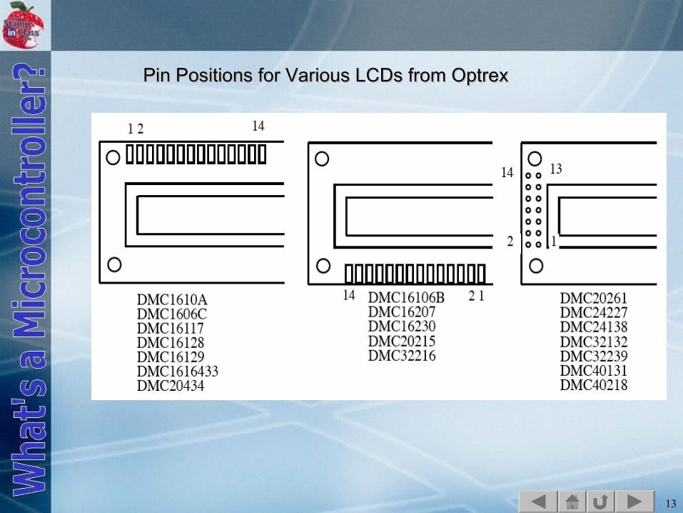
Pin Positions for Various LCDs from OptrexPin Positions for Various LCDs from Optrex
14
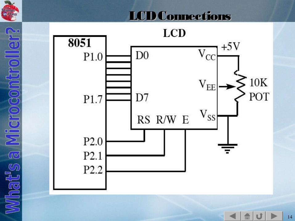
LCD ConnectionsLCD Connections
15
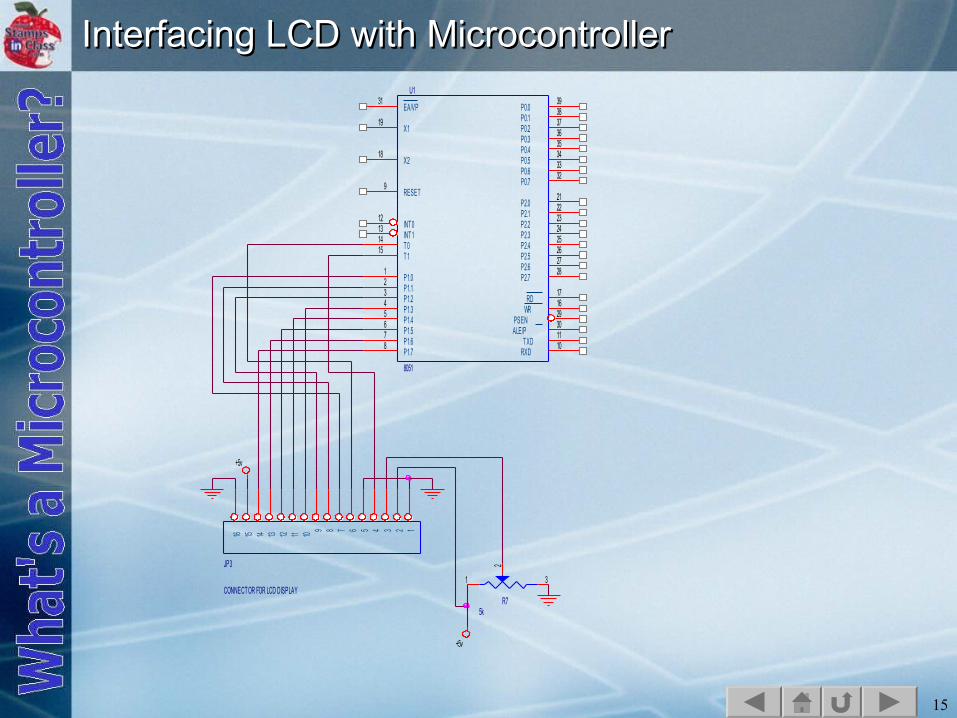
Interfacing LCD with MicrocontrollerInterfacing LCD with Microcontroller
+5v
+5v
JP3
CONNECTOR FOR LCD DISPLAY
12345678910111213141516
R75k
1 3
2
U1
8051
31
19
18
9
12131415
12345678
3938373635343332
2122232425262728
171629301110
EA/VP
X1
X2
RESET
INT0INT1T 0T 1
P1.0P1.1P1.2P1.3P1.4P1.5P1.6P1.7
P0.0P0.1P0.2P0.3P0.4P0.5P0.6P0.7
P2.0P2.1P2.2P2.3P2.4P2.5P2.6P2.7
RDWR
PSENALE/P
TXDRXD
16
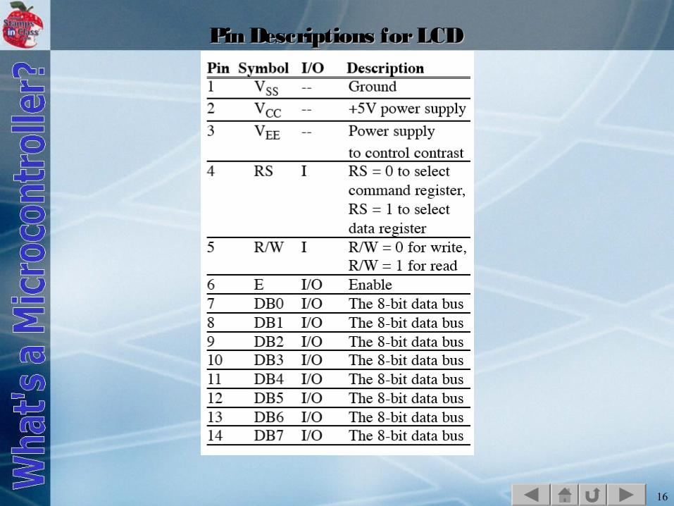
Pin Descriptions for LCDPin Descriptions for LCD
17
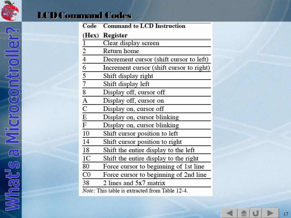
LCD Command CodesLCD Command Codes

18
19
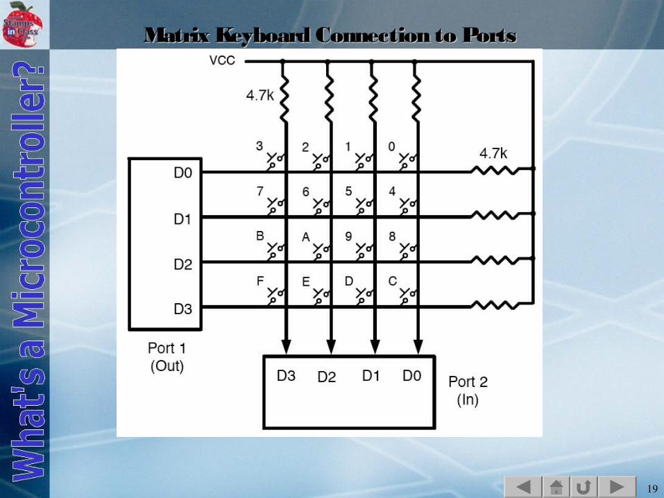
Matrix Keyboard Connection to PortsMatrix Keyboard Connection to Ports

20
FlowchartFlowchart
21
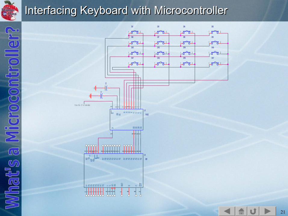
Interfacing Keyboard with MicrocontrollerInterfacing Keyboard with Microcontroller
U5
74C922
12341110875613
1716151412
Y1Y2Y3Y4X1X2X3X4
OSCKBMOE
DOA
DOB
DOC
DOD
DA
U6
8051
31191891213141512345678
39383736353433322122232425262728171629301110
EA/VP
X1X2RESE
T
INT0
INT1
T0T1P1.0
P1.1
P1.2
P1.3
P1.4
P1.5
P1.6
P1.7
P0.0
P0.1
P0.2
P0.3
P0.4
P0.5
P0.6
P0.7
P2.0
P2.1
P2.2
P2.3
P2.4
P2.5
P2.6
P2.7RDWR
PSEN
ALE/PTX
DRX
D
SW1
1 2
SW3
1 2
SW4
1 2
SW5
1 2
SW6
1 2
SW7
1 2
SW8
1 2
SW9
1 2
SW10
1 2
SW11
1 2
SW12
1 2
SW13
1 2
SW14
1 2
SW15
1 2
SW16
1 2
SW17
1 2
C1
C2
From Pin 15 of decoder

22
23
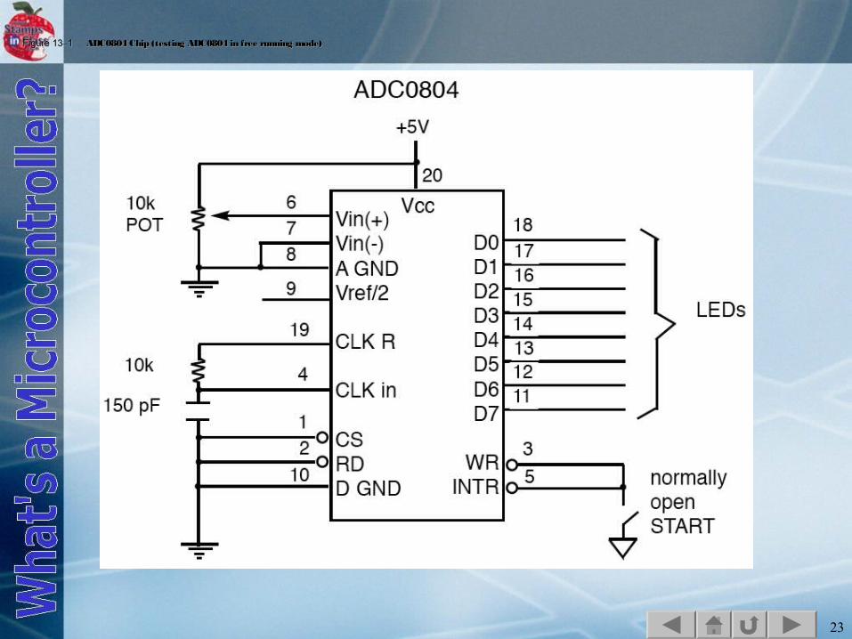
Figure 13Figure 13––1 1 ADC0804 Chip (testing ADC0804 in free running mode)ADC0804 Chip (testing ADC0804 in free running mode)
24
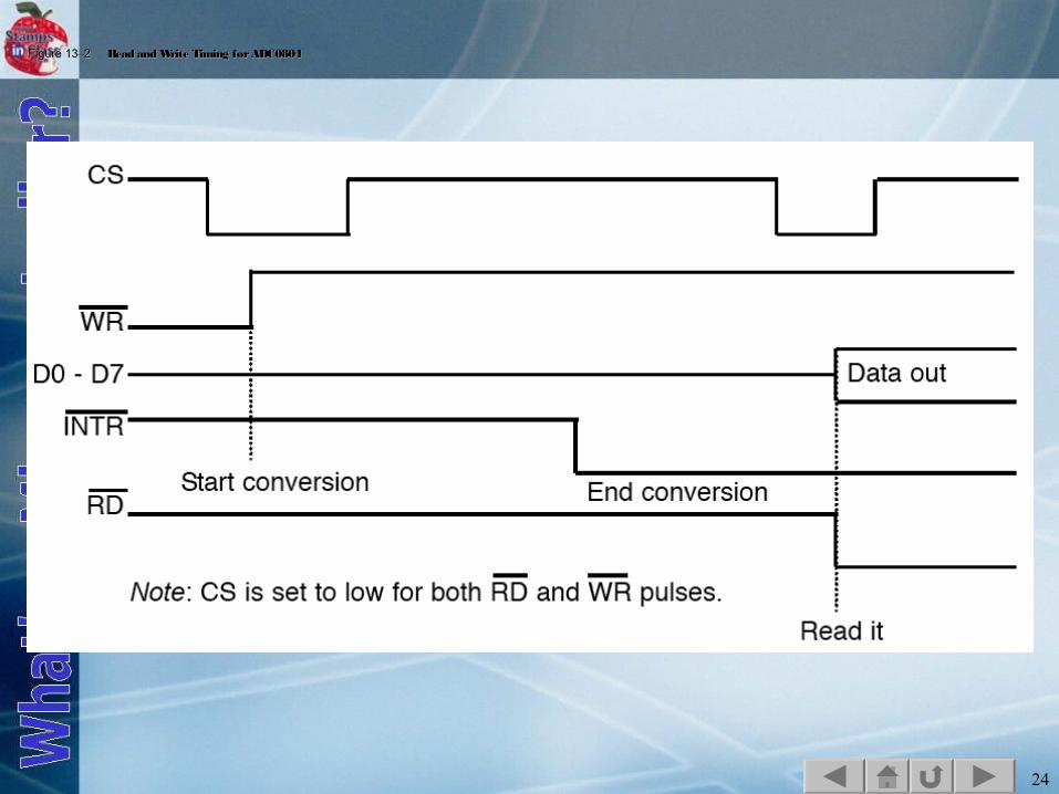
Figure 13Figure 13––2 2 Read and Write Timing for ADC0804Read and Write Timing for ADC0804
25
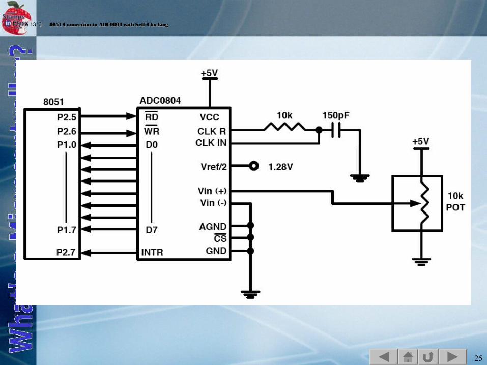
Figure 13Figure 13––3 3 8051 Connection to ADC0804 with Self-Clocking8051 Connection to ADC0804 with Self-Clocking
26
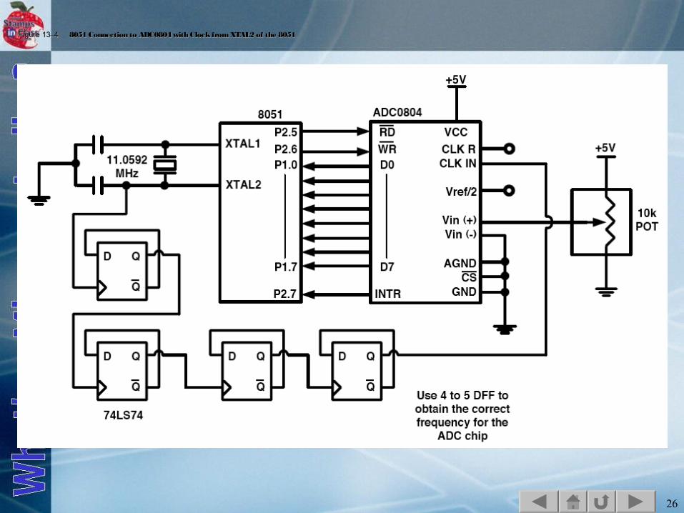
Figure 13Figure 13––4 4 8051 Connection to ADC0804 with Clock from XTAL2 of the 80518051 Connection to ADC0804 with Clock from XTAL2 of the 8051
27
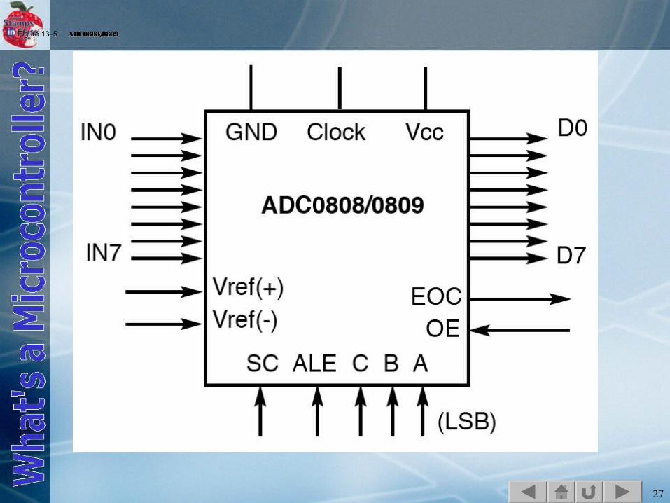
Figure 13Figure 13––5 5 ADC0808/0809 ADC0808/0809
28
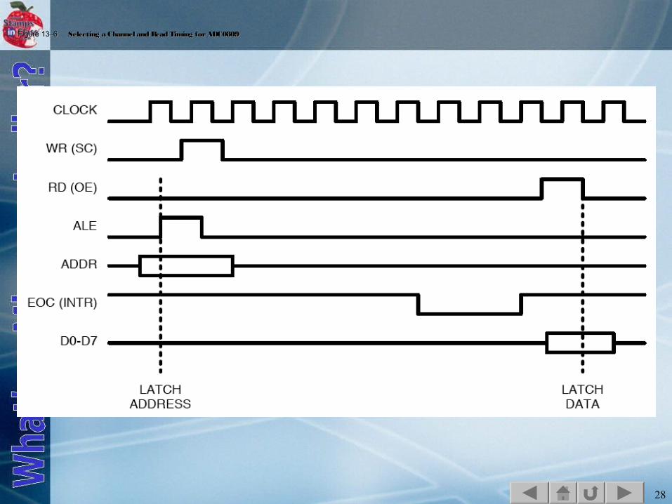
Figure 13Figure 13––6 6 Selecting a Channel and Read Timing for ADC0809Selecting a Channel and Read Timing for ADC0809
29
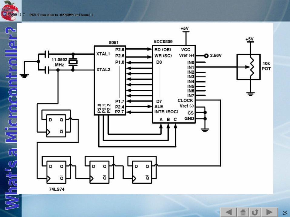
Figure 13Figure 13––7 7 8051 Connection to ADC0809 for Channel 18051 Connection to ADC0809 for Channel 1