Embed Size (px)
Citation preview

International Journal of Research in Science & Technology Volume 2 | Issue 4 | April 2015 | ISSN: 2349-0845
Integration of Unified Power Quality Controller with DG
Page 5
Integration of Unified Power Quality Controller with
DG
Sk. Chinni Bhavani1, T. Prasanth
2 , V. Srilekha
3 , P. Phaneendra
4 and Mrs. M. Anitha
5
1, 2, 3, 4UG Students, Department of EEE, RVR & JC College of Engineering, Guntur, A.P, India. 5Assistant Professor, Department of EEE, RVR & JC College of Engineering, Guntur, A.P, India.
Article Info ABSTRACT
Article history:
Received on 19th April 2015
Accepted on 24th April 2015
Published on 29th April 2015
This paper gives an insight into the analytical results of the intergration of
Unified power quality controller (conditioner) with distribution generation
system. The intergration is achieved by connecting the DClink throught
rectifier to the distribution generatoion along with thwe connection of the
series and shunt inverter to the same dc link. This type of connection can
account for the voltage sag, voltage swell, along with the reduction of
harmonics and also compensation of reactive power. The analysis is
supported with the simulation which will are discussed in detail in the paper.
Keyword:
Controller,
Integration,
Voltage swell
Voltage sag
Copyright © 2015 International Journal of Research in Science & Technology
All rights reserved.
Corresponding Author:
Smt M.Anitha Assistant Professor in EEE Department,
RVR & JC College of Engineering,
Guntur, India
Email Id: [email protected]
International Journal of Research in Science & Technology Volume 2 | Issue 4 | April 2015 | ISSN: 2349-0845
Integration of Unified Power Quality Controller with DG
Page 6
I. INTRODUCTION
Power quality determines the fitness of
electric power to consumer devices. Synchronization of the
voltage frequency and phase allows electrical systems to
function in their intended manner without significant loss
of performance or life.
The main reason for the power quality problems to
arise is due to circuit breakers trip, equipment failure .
UPQC is the device that is used to improve power quality
but due to absence of energy storage it cant mitigate
voltage interruption
II. BASIC CONFIGURATION OF UPQC
A UPQC is a combination of shunt and series APFs,
sharing a common dc link. It is a versatile device that can
compensate almost all power quality problems such as
voltage harmonics, voltage unbalance, voltage flickers,
voltage sags & swells, current harmonics, current
unbalance, reactive current, etc. The Unified Power
Quality Conditioner (UPQC) has evolved to be one of the
most comprehensive custom power solutions for power
quality issues relating to non-linear harmonic producing
loads and the effect of utility voltage disturbance on
sensitive industrial loads.
Figure 1 Basic Configuration of UPQC
III. UPQC WITH DG
This paper proposes a new configuration of UPQC
that has a DG connected to the dc link through the rectifier
as shown in Fig. 1. The UPQC can compensate the voltage
interruption in the source, while the DG supplies power to
the source and load or the load only. There are two
operation modes in the proposed system. One is called the
interconnected mode, in which the DG provides power to
the source and the load. The other is called the islanding
mode, in which the DG provides power to the load only
within its power rating.
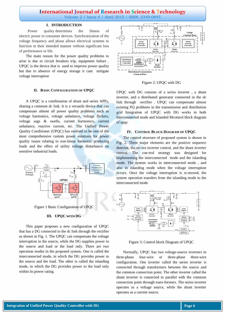
Figure 2: UPQC with DG
UPQC with DG consists of a series inverter , a shunt
inverter, and a distributed generator connected in the dc
link through rectifier . UPQC can compensate almost
existing PQ problems in the transmission and distribution
grid Integration of UPQC with DG works in both
Interconnected mode and Islanded Mcontrol block diagram
of upqc
IV. CONTROL BLOCK DIAGRAM OF UPQC
The control structure of proposed system is shown in
Fig. 2. Three major elements are the positive sequence
detector, the se-ries inverter control, and the shunt inverter
control. The con-trol strategy was designed for
implementing the interconnected mode and the islanding
mode. The system works in interconnected mode , and
also in islanding mode when the voltage interruption
occurs. Once the voltage interruption is re-moved, the
system operation transfers from the islanding mode to the
interconnected mode
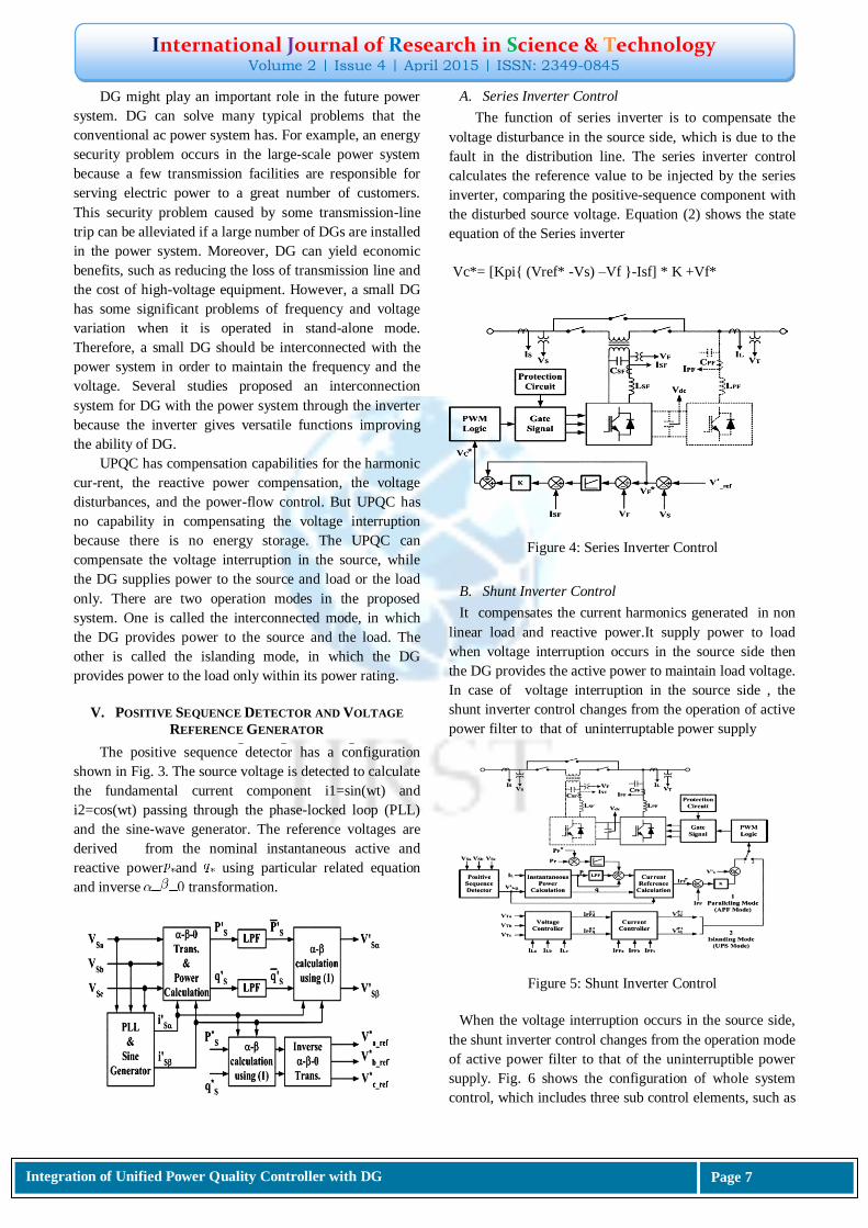
Figure 3: Control block Diagram of UPQC
Normally, UPQC has two voltage-source inverters in
three-phase four-wire or three-phase three-wire
configuration. One inverter called the series inverter is
connected through transformers between the source and
the common connection point. The other inverter called the
shunt inverter is connected in parallel with the common
connection point through trans-formers. The series inverter
operates as a voltage source, while the shunt inverter
operates as a current source.
International Journal of Research in Science & Technology Volume 2 | Issue 4 | April 2015 | ISSN: 2349-0845
Integration of Unified Power Quality Controller with DG
Page 7
DG might play an important role in the future power
system. DG can solve many typical problems that the
conventional ac power system has. For example, an energy
security problem occurs in the large-scale power system
because a few transmission facilities are responsible for
serving electric power to a great number of customers.
This security problem caused by some transmission-line
trip can be alleviated if a large number of DGs are installed
in the power system. Moreover, DG can yield economic
benefits, such as reducing the loss of transmission line and
the cost of high-voltage equipment. However, a small DG
has some significant problems of frequency and voltage
variation when it is operated in stand-alone mode.
Therefore, a small DG should be interconnected with the
power system in order to maintain the frequency and the
voltage. Several studies proposed an interconnection
system for DG with the power system through the inverter
because the inverter gives versatile functions improving
the ability of DG.
UPQC has compensation capabilities for the harmonic
cur-rent, the reactive power compensation, the voltage
disturbances, and the power-flow control. But UPQC has
no capability in compensating the voltage interruption
because there is no energy storage. The UPQC can
compensate the voltage interruption in the source, while
the DG supplies power to the source and load or the load
only. There are two operation modes in the proposed
system. One is called the interconnected mode, in which
the DG provides power to the source and the load. The
other is called the islanding mode, in which the DG
provides power to the load only within its power rating.
V. POSITIVE SEQUENCE DETECTOR AND VOLTAGE
REFERENCE GENERATOR
The positive sequence detector has a configuration
shown in Fig. 3. The source voltage is detected to calculate
the fundamental current component i1=sin(wt) and
i2=cos(wt) passing through the phase-locked loop (PLL)
and the sine-wave generator. The reference voltages are
derived from the nominal instantaneous active and
reactive power and using particular related equation
and inverse transformation.
A. Series Inverter Control
The function of series inverter is to compensate the
voltage disturbance in the source side, which is due to the
fault in the distribution line. The series inverter control
calculates the reference value to be injected by the series
inverter, comparing the positive-sequence component with
the disturbed source voltage. Equation (2) shows the state
equation of the Series inverter
Vc*= [Kpi{ (Vref* -Vs) –Vf }-Isf] * K +Vf*
Figure 4: Series Inverter Control
B. Shunt Inverter Control
It compensates the current harmonics generated in non
linear load and reactive power.It supply power to load
when voltage interruption occurs in the source side then
the DG provides the active power to maintain load voltage.
In case of voltage interruption in the source side , the
shunt inverter control changes from the operation of active
power filter to that of uninterruptable power supply
Figure 5: Shunt Inverter Control
When the voltage interruption occurs in the source side,
the shunt inverter control changes from the operation mode
of active power filter to that of the uninterruptible power
supply. Fig. 6 shows the configuration of whole system
control, which includes three sub control elements, such as
International Journal of Research in Science & Technology Volume 2 | Issue 4 | April 2015 | ISSN: 2349-0845
Integration of Unified Power Quality Controller with DG
Page 8
the current control for harmonic compensation, and the
output voltage control in voltage interruption
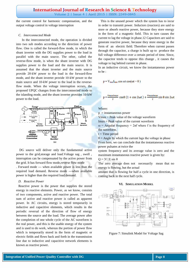
C. Interconnected Mode
In the interconnected mode, the operation is divided
into two sub modes according to the direction of power
flow. One is called the forward-flow mode, in which the
shunt inverter with the DG supplies power to the load in
parallel with the main source. The other, called the
reverse-flow mode, is when the shunt inverter with DG
supplies power to the load and the main source. It is
assumed that the shunt inverter and the main source
provide 20-kW power to the load in the forward-flow
mode, and the shunt inverter provide 10-kW power to the
main source and 10-kW power to the load in the reverse-
flow mode. When the voltage interruption occurs, the
proposed UPQC changes from the interconnected mode to
the islanding mode, and the shunt inverter provides 10-kW
power to the load.
DG source will deliver only the fundamental active
power to the grid,storage and load.Voltage sag , swell ,
interruption can be compensated by the active power from
the grid. It has forward flow mode,reverse flow mode
. Forward mode --- when available power is less than the
required load demand. Reverse mode ---when available
power is higher than the required load demand.
D. Reactive Power
Reactive power is the power that supplies the stored
energy in reactive elements. Power, as we know, consists
of two components, active and reactive power. The total
sum of active and reactive power is called as apparent
power. In AC circuits, energy is stored temporarily in
inductive and capacitive elements, which results in the
periodic reversal of the direction of flow of energy
between the source and the load. The average power after
the completion of one whole cycle of the AC waveform is
the real power, and this is the usable energy of the system
and is used to do work, whereas the portion of power flow
which is temporarily stored in the form of magnetic or
electric fields and flows back and forth in the transmission
line due to inductive and capacitive network elements is
known as reactive power.
This is the unused power which the system has to incur
in order to transmit power. Inductors (reactors) are said to
store or absorb reactive power, because they store energy
in the form of a magnetic field. This in turn causes the
current to lag the voltage in phase.12 Capacitors are said to
generate reactive power, because they store energy in the
form of an electric field. Therefore when current passes
through the capacitor, a charge is built up to produce the
full voltage difference over a certain period of time. Since,
the capacitor tends to oppose this change , it causes the
voltage to lag behind current in phase.
In an inductive circuit, we know the instantaneous power
to be :
Where:
p = instantaneous power
Vmax = Peak value of the voltage waveform
Imax = Peak value of the current waveform
ω = Angular frequency = 2πf where f is the frequency of
the waveform.
t = Time period
θ = Angle by which the current lags the voltage in phase
From here, we can conclude that the instantaneous reactive
power pulsates at twice the
system frequency and its average value is zero and the
maximum instantaneous reactive power is given by:
Q = |V| |I| sin θ
The zero average does not necessarily mean that no
energy is flowing, but the actual
amount that is flowing for half a cycle in one direction, is
coming back in the next half cycle.
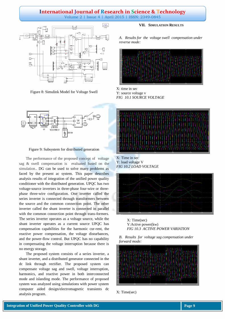
VI. SIMULATION MODEL
Figure 7: Simulink Model for Voltage Sag
International Journal of Research in Science & Technology Volume 2 | Issue 4 | April 2015 | ISSN: 2349-0845
Integration of Unified Power Quality Controller with DG
Page 9
Figure 8: Simulink Model for Voltage Swell
Figure 9: Subsystem for distributed generation
The performance of the proposed concept of voltage
sag & swell compensation is evaluated based on the
simulation.. DG can be used to solve many problems as
faced by the present ac system. This paper describes
analysis results of integration of the unified power quality
conditioner with the distributed generation. UPQC has two
voltage-source inverters in three-phase four-wire or three-
phase three-wire configuration. One inverter called the
series inverter is connected through transformers between
the source and the common connection point. The other
inverter called the shunt inverter is connected in parallel
with the common connection point through trans-formers.
The series inverter operates as a voltage source, while the
shunt inverter operates as a current source UPQC has
compensation capabilities for the harmonic cur-rent, the
reactive power compensation, the voltage disturbances,
and the power-flow control. But UPQC has no capability
in compensating the voltage interruption because there is
no energy storage.
The proposed system consists of a series inverter, a
shunt inverter, and a distributed generator connected in the
dc link through rectifier. The proposed system can
compensate voltage sag and swell, voltage interruption,
harmonics, and reactive power in both interconnected
mode and islanding mode. The performance of proposed
system was analyzed using simulations with power system
computer aided design/electromagnetic transients dc
analysis program.
VII. SIMULATION RESULTS
A. Results for the voltage swell compensation under
reverse mode:
X: time in sec
Y: source voltage v
FIG 10.1 SOURCE VOLTAGE
X: Time in sec
Y: load voltage V
FIG 10.2 LOAD VOLTAGE
B. Results for voltage sag compensation under forward mode:
X: Time(sec)
X: Time(sec) Y:Active power(kw)
FIG 10.3 ACTIVE POWER VARIATION
International Journal of Research in Science & Technology Volume 2 | Issue 4 | April 2015 | ISSN: 2349-0845
Integration of Unified Power Quality Controller with DG
Page 10
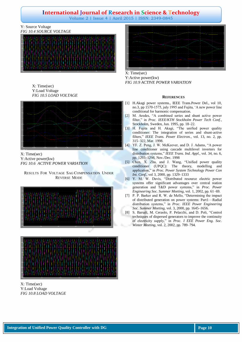
Y: Source Voltage
FIG 10.4 SOURCE VOLTAGE
X: Time(sec)
Y:Active power(kw)
FIG 10.6 ACTIVE POWER VARIATION
RESULTS FOR VOLTAGE SAG COMPENSATION UNDER
REVERSE MODE
X: Time(sec)
Y:Load Voltage
FIG 10.8 LOAD VOLTAGE
X: Time(sec)
Y:Active power(kw)
FIG 10.9 ACTIVE POWER VARIATION
REFERENCES
[1] H.Akagi power systems., IEEE Trans.Power Del., vol 10, no.3, pp 1570-1575, july 1995 and Fujita, ‗A new power line conditional for harmonic compensation.
[2] M. Aredes, ―A combined series and shunt active power filter,‖ in Proc. IEEE/KTH Stockholm Power Tech Conf., Stockholm, Sweden, Jun. 1995, pp. 18–22.
[3] H. Fujita and H. Akagi, ―The unified power quality conditioner: The integration of series and shunt-active filters,‖ IEEE Trans. Power Electron., vol. 13, no. 2, pp. 315–322, Mar. 1998.
[4] YF. Z. Peng, J. W. McKeever, and D. J. Adams, ―A power line conditioner using cascade multilevel inverters for distribution systems,‖ IEEE Trans. Ind. Appl., vol. 34, no. 6, pp. 1293–1298, Nov./Dec. 1998
[5] Chen, X. Zha, and J. Wang, ―Unified power quality conditioner (UPQC): The theory, modelling and application,‖ in Proc. Power System Technology Power Con Int. Conf., vol 3, 2000, pp. 1329–1333
[6] Y. M. W. Davis, ―Distributed resource electric power systems offer significant advantages over central station generation and T&D power systems,‖ in Proc. Power Engineering Soc. Summer Meeting, vol. 1, 2002, pp. 61–69.
[7] P. P. Barker and R. W. de Mello, ―Determining the impact
of distributed generation on power systems: Part1—Radial distribution systems,‖ in Proc. IEEE Power Engineering Soc. Summer Meeting, vol. 3, 2000, pp. 1645–1656.
[8] S. Barsali, M. Ceraolo, P. Pelacchi, and D. Poli, ―Control techniques of dispersed generators to improve the continuity of electricity supply,‖ in Proc. I EEE Power Eng. Soc. Winter Meeting, vol. 2, 2002, pp. 789–794.
X: Time(sec)
Y:Load Voltage
FIG 10.5 LOAD VOLTAGE