Embed Size (px)
Citation preview
HEAT TRANSFER ENHANCEMENT IN PIPE FLOW
A SEMINAR REPORTSubmitted by
Haidar Majeed Hachim
In partial fulfillment for the award of the degreeOf
MASTER OF POWER PLANTIN
MECHANICAL ENGINEERINGProf. Dr. veysel ozceyhan
The need to increase the thermal performance of heat transfer
equipment (for instance heat exchangers) thereby effecting energy ,material and cost saving has led to the development and use of many heat transfer enhancement techniques this seminar deals with the analysis of heat transfer augmentation for fluid flowing through pipes using CFD .using CFD for modeling the heat and fluid flow is an efficient tool for predicting equipment performance .CFD offers a convenient means to study the detailed flows and heat exchange process which takes place inside the tube .friction factor and Nusselt number for air flowing through the specified pipe (diameter 0.06 m ,length 0.8m)were obtained first for smooth pipe and second for roughened pipe.in this seminar the factor that affect the enhancement techniques using roughened pipes are studied. these factor are the ratio of(pitch/pipe diameter),Reynolds numbers
ABSTRACT
The results showed that there is an increase in
heat transfer coefficient is related to the decreasing of ratio of pitch/pipe length ,increasing of Reynolds number .the performance of roughened pipe is evaluated depending on the calculation of thermo-hydraulic performance(THP)and its found that the thermo-hydraulic performance increase as Reynolds number increase and (pitch/pipe daimeter)decrease
ABSTRACT
High performance heat transfer system is great
importance in many industrial applications. The performance of conventional heat exchangers can be substantially improved by a number of heat transfer enhancement techniques.. The process industry is continuously working to incorporate enhancement in heat transfer. Enhancement techniques can be classified as active methods, which require external power and Passive methods, which require no direct application of external power.
INTRODUCTION

The enhanced surfaces are routinely used to
improve thermal and hydraulic performance of heat exchangers. Experimental investigation of heat transfer of circular tube(smooth and roughened pipe) have been studied under uniform heat flux conditions. Air is used as working fluid.
INTRODUCTION

To make the equipment compact To achieve a high heat transfer rate using minimize pumping
power Minimize the cost of energy and material A need for miniaturization of a heat exchanger in specific
applications space, OTEC Working fluids of low thermal conductivity (gases and oils )and
desalination plants Increase efficiency of process and system Design optimum heat exchanger size Transfer required amount of heat with high effectiveness Reduce the volume and weight For given temperature difference improved heat transfer Effective utilization of energy – minimum operating cost
Why need heat transfer enhancement
Active method:-external power input for the
enhancement of heat transfer Passive method:-surface or geometrical
modification to the flow channel by incorporating inserts or additional devices
Compound method:-when any two or more techniques employed simultaneously
Heat transfer enhancement techniques

Treated surface are heat transfer surface that have
affine –scale alteration to their finish or coating .the alteration could be continuous or discontinuous, where the roughness is much smaller than what affects single-phase heat transfer, and they are used primarily for boiling and condensing duties..
Rough surface are generally surface modification that promote turbulence in the flow field, primarily in the single phase flows , and do not increase the heat transfer surface area. Their geometric features range from random sand-grain roughness to discrete three-dimensional,
PASSIVE TECHNIQUES
Extended surfaces, more commonly referred to as finned
surfaces, provide an effective heat transfer surface area enlargement. Plain fins have been used routinely in many heat exchangers. The newer developments, however, have led to modified finned surfaces that also tend to improve the heat transfer coefficients by disturbing the flow field in addition to increasing the surface area
Displaced enhancement device are inserts that are used primarily in confined forced convection, and they improve energy transport indirectly at the heat exchange surface by “displacing” the fluid from the heated or cooled surface of the duct with bulk fluid from the core flow
PASSIVE TECHNIQUES
Swirl flow devices produce and superimpose swirl or
secondary recirculation on the axial flow in a channel. They include helical strip or cored screw-type tube inserts, twisted ducts, and various forms of altered (tangential to axial direction) flow arrangements, and they can be used for single-phase as well as two-phase flows
Coiled tubes are what the name suggests, and they lead to relatively more compact heat exchangers. The tube curvature due to coiling produces secondary flows, which promote higher heat transfer coefficients in single-phase flows as well as in most regions of boiling.
PASSIVE TECHNIQUES
Surface tension devices consist of wicking or grooved
surfaces, which direct and improve the flow of liquid to boiling surfaces and from condensing surfaces
Additives for liquids include the addition of solid particles, soluble trace additives, and gas bubbles in single-phase flows, and trace additives, which usually depress the surface tension of the liquid, for boiling systems
Additives for gases include liquid droplets or solid particles, which are introduced in single-phase gas flows in either a dilute phase (gas–solid suspensions) or dense phase (fluidized beds).
PASSIVE TECHNIQUES

Mechanical aids are those that stir the fluid by
mechanical mean or by rotating the surface. The more prominent examples include rotating tube heat exchangers and scraped-surface heat and mass exchangers
Surface vibration has been applied primarily, at either low or high frequency, in single phase flows to obtain higher convective heat transfer coefficients
Active techniques-:
Fluid vibration or fluid pulsation, with vibrations
ranging from 1.0 Hz to ultrasound, used primarily in single-phase flows, is considered to be perhaps the most practical type of vibration enhancement technique
Electrostatic fields which could be in the form of electric or magnetic fields, or a combination of the two, from dc or ac sources, can be applied in heat exchange systems involving dielectric fluids. Depending on the application, they can promote greater bulk fluid mixing and induce forced convection (corona “wind”) or electromagnetic pumping to enhance heat transfer
Active techniques
Injection, used only in single-phase flow, pertains to the
method of injecting the same or a different fluid into the main bulk fluid either through a porous heat transfer interface or upstream of the heat transfer section
Suction involves either vapor removal through a porous heated surface in nucleate or film boiling, or fluid withdrawal through a porous heated surface in single-phase flow
Jet impingement involves the direction of heating or cooling fluid perpendicularly or obliquely to the heat transfer surface. Single or multiple jets (in clusters or staged axially along the flow channel) may be used in both single-phase and boiling applications
Active techniques

1.These techniques generally use simple
surface or geometrical modifications to the flow channel by incorporation inserts or additional devices
2. It does not need any external power input 3.Insert manufacturing process is simple and
these techniques can be easily employed in an existing heat exchanger
Why passive techniques
4.Passive insert configuration can be selected
according to the heat exchanger working condition
5.It can be used in design of compact heat exchangers
6.It is not only applicable in heat exchanger but also in solar air heater and cooling of electronic components(heat sink)
Why passive techniques
Use of secondary heat transfer surface Disruption the laminar sub layer in the
turbulent boundary layer Disruption of the unenhanced fluid velocity Introduction secondary flows Promoting boundary –layer separation Enhancing effective thermal conductivity of the
fluid under static conditions Enhancing effective thermal conductivity of the
fluid under dynamic Delaying the boundary layer development
Mechanisms of augmentation of heat transfer
Thermal dispersion Increasing the order of the fluid molecules Redistribution of the flow Modification of radiative property of the
convective medium Increasing the difference between the
surface and fluid temperature Increasing fluid flow rate passively Increasing the thermal conductivity of the
solid phase using special nanotechnology fabrications
Mechanisms of augmentation of heat transfer
Resistance to heat transfer should be minimized Contingencies should be anticipated via safety
margins; for example, allowance for fouling during operation
The equipment should be sturdy Cost and material requirements should be low. Corrosion should be avoided Pumping cost should be kept low Space required should be kept low. Required weight should be kept low
DESIGN CONSIDERATIONS
Power plant Air conditioning Refrigeration Process industry Solar water heater Shell and tube heat exchanger Nuclear reactor
application
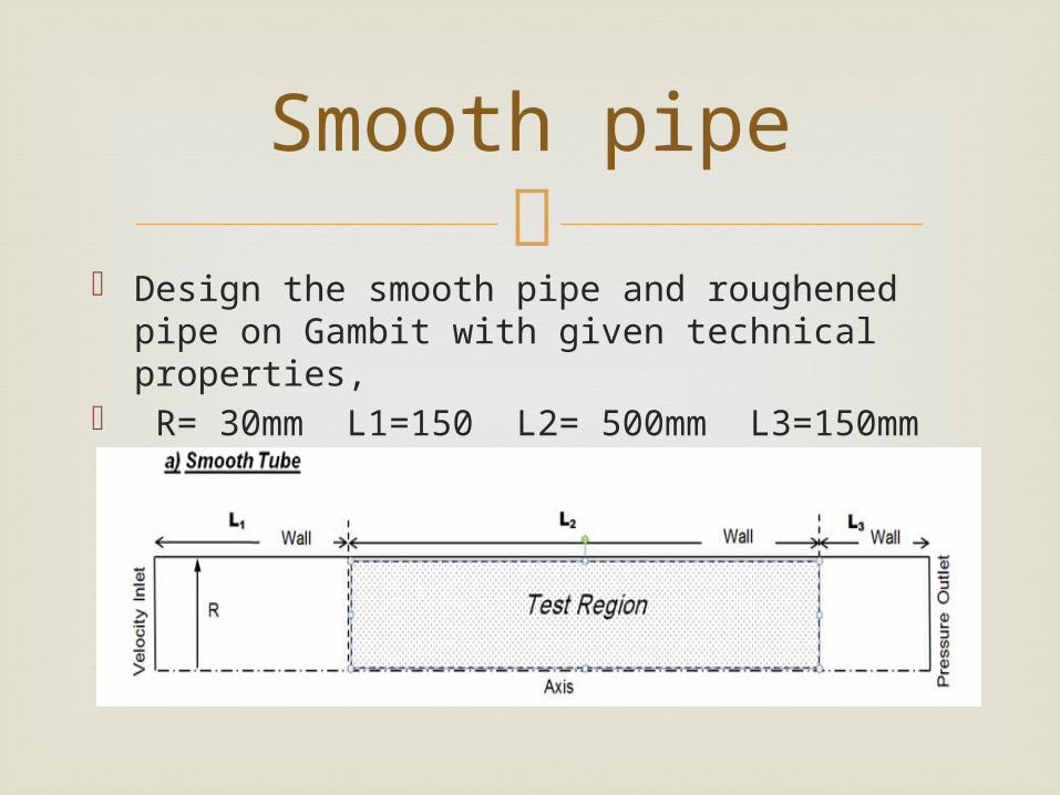
Design the smooth pipe and roughened pipe
on Gambit with given technical properties, R= 30mm L1=150 L2= 500mm L3=150mm
a= 5mm P= 30,60 ,120,180 and solve the problem at Fluent.
Smooth pipe
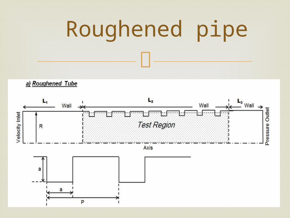
Roughened pipe

L1: Adiabatic wall (Aluminium) L2: Constant heat flux(1500 W/m2)
(Aluminium) L3: Adiabatic wall (Aluminium) Velocity inlet: For Velocity 0.5, 1.0 1.5, 2.0, 2.5
m/s values analysis should be done seperately. Pressure outlet: Gauge Pressure 0 kPa Fluid: Air (ρ=1.225 kg/m3, Cp=1007
j/kgK, k=0.0242 W/mK, μ=1.7894e-5 kg/ms)
Boundry Conditions
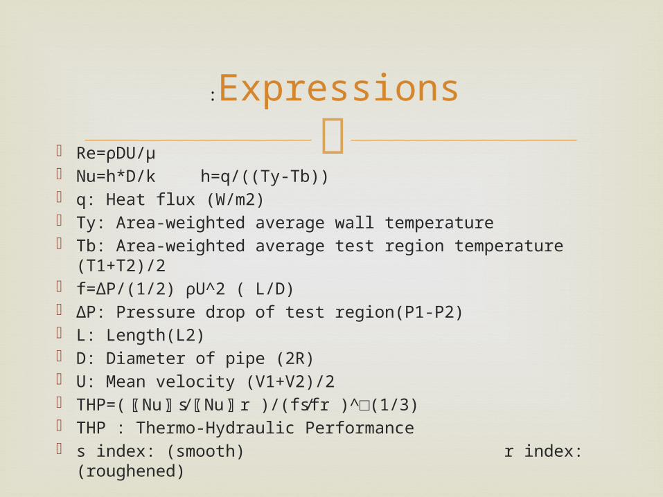
Re=ρDU/μ Nu=h*D/k h=q/((Ty-Tb)) q: Heat flux (W/m2) Ty: Area-weighted average wall temperature Tb: Area-weighted average test region temperature
(T1+T2)/2 f=∆P/(1/2) ρU^2 ( L/D) ΔP: Pressure drop of test region(P1-P2) L: Length(L2) D: Diameter of pipe (2R) U: Mean velocity (V1+V2)/2 THP=(〖Nu〗 s⁄〖Nu〗 r )/(fs⁄fr )^□(1/3) THP : Thermo-Hydraulic Performance s index: (smooth) r index: (roughened)
Expressions:
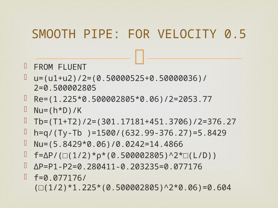
FROM FLUENT u=(u1+u2)/2=(0.50000525+0.50000036)/
2=0.500002805 Re=(1.225*0.500002805*0.06)/2=2053.77 Nu=(h*D)/K Tb=(T1+T2)/2=(301.17181+451.3706)/2=376.27 h=q/(Ty-Tb )=1500/(632.99-376.27)=5.8429 Nu=(5.8429*0.06)/0.0242=14.4866 f=∆P/(□(1/2)*ρ*(0.500002805)^2*□(L/D)) ∆P=P1-P2=0.280411-0.203235=0.077176 f=0.077176/
(□(1/2)*1.225*(0.500002805)^2*0.06)=0.604
SMOOTH PIPE: FOR VELOCITY 0.5
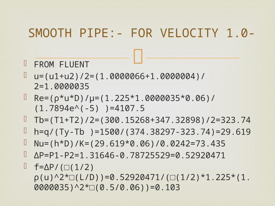
FROM FLUENT u=(u1+u2)/2=(1.0000066+1.0000004)/
2=1.0000035 Re=(ρ*u*D)/μ=(1.225*1.0000035*0.06)/
(1.7894e^(-5) )=4107.5 Tb=(T1+T2)/2=(300.15268+347.32898)/2=323.74 h=q/(Ty-Tb )=1500/(374.38297-323.74)=29.619 Nu=(h*D)/K=(29.619*0.06)/0.0242=73.435 ∆P=P1-P2=1.31646-0.78725529=0.52920471 f=∆P/(□(1/2)
ρ(u)^2*□(L/D))=0.52920471/(□(1/2)*1.225*(1.0000035)^2*□(0.5/0.06))=0.103
-SMOOTH PIPE:- FOR VELOCITY 1.0
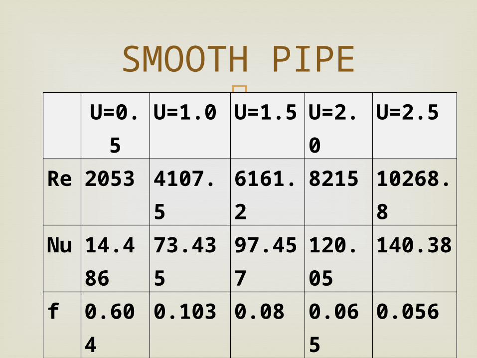
U=0.5 U=1.0 U=1.5 U=2.0 U=2.5
Re 2053 4107.5 6161.2 8215 10268.8
Nu 14.486 73.435 97.457 120.05 140.38
f 0.604 0.103 0.08 0.065 0.056
SMOOTH PIPE
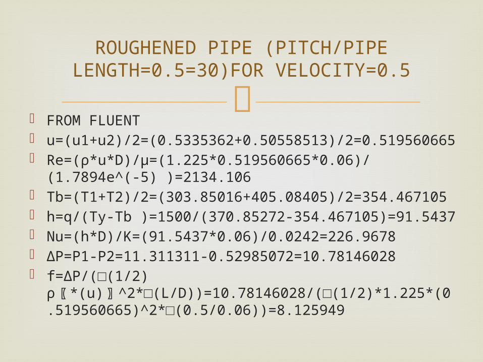
FROM FLUENT u=(u1+u2)/2=(0.5335362+0.50558513)/
2=0.519560665 Re=(ρ*u*D)/μ=(1.225*0.519560665*0.06)/(1.7894e^(-
5) )=2134.106 Tb=(T1+T2)/2=(303.85016+405.08405)/2=354.467105 h=q/(Ty-Tb )=1500/(370.85272-354.467105)=91.5437 Nu=(h*D)/K=(91.5437*0.06)/0.0242=226.9678 ∆P=P1-P2=11.311311-0.52985072=10.78146028 f=∆P/(□(1/2)
ρ〖 *(u)〗^2*□(L/D))=10.78146028/(□(1/2)*1.225*(0.519560665)^2*□(0.5/0.06))=8.125949
ROUGHENED PIPE (PITCH/PIPE LENGTH=0.5=30)FOR VELOCITY=0.5
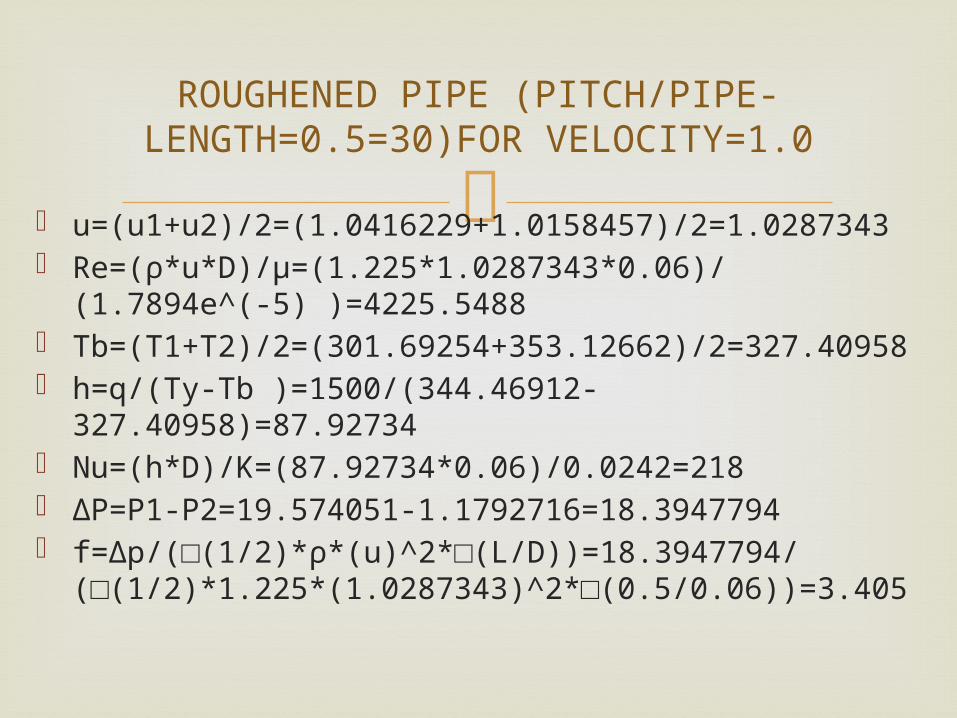
u=(u1+u2)/2=(1.0416229+1.0158457)/2=1.0287343
Re=(ρ*u*D)/μ=(1.225*1.0287343*0.06)/(1.7894e^(-5) )=4225.5488
Tb=(T1+T2)/2=(301.69254+353.12662)/2=327.40958
h=q/(Ty-Tb )=1500/(344.46912-327.40958)=87.92734
Nu=(h*D)/K=(87.92734*0.06)/0.0242=218 ∆P=P1-P2=19.574051-1.1792716=18.3947794 f=∆p/(□(1/2)*ρ*(u)^2*□(L/D))=18.3947794/
(□(1/2)*1.225*(1.0287343)^2*□(0.5/0.06))=3.405
-ROUGHENED PIPE (PITCH/PIPE LENGTH=0.5=30)FOR VELOCITY=1.0

U=0.5 U=1.0 U=1.5 U=2.0 U=2.5
Re 2134.10 4225.548 6339.8 8523.2 10697
Nu 226.967 218 199.076 194.055 199.88
f 8.12594 3.405 2.16318 1.61839 1.2454
ROUGHENED PIPE (PITCH/PIPE diameter=0.5=30)

FROM FLUENT:- P1=7.2058 P2=0.4881
u1=0.50002795 u2=0.50007921 Ty=360.847 T1=303.6272 T2=392.6641
u=(u1+u2)/2=(0.50002795+0.50007921)/2=0.50005358 Re=(ρ*u*D)/μ=(1.225*0.50005358*0.06)/(1.7894e^(-
5) )=2053 Tb=(T1+T2)/2=(303.6272+392.6641)/2=348.14565 h=q/(Ty-Tb )=1500/(360.847-348.14565)=118.09 Nu=(h*D)/K=(118.09*0.06)/0.0242=292.80 ∆P=P1-P2=7.2058-0.4881=6.7177 f=∆P/(□(1/2)*ρ*(u)^2*□(L/D))=6.7177/
(□(1/2)*1.225*(0.50005358)^2*□(0.5/0.06))=5.2633
ROUGHENED PIPE (PITCH/PIPE LENGTH=1=60) FOR VELOCITY=0.5
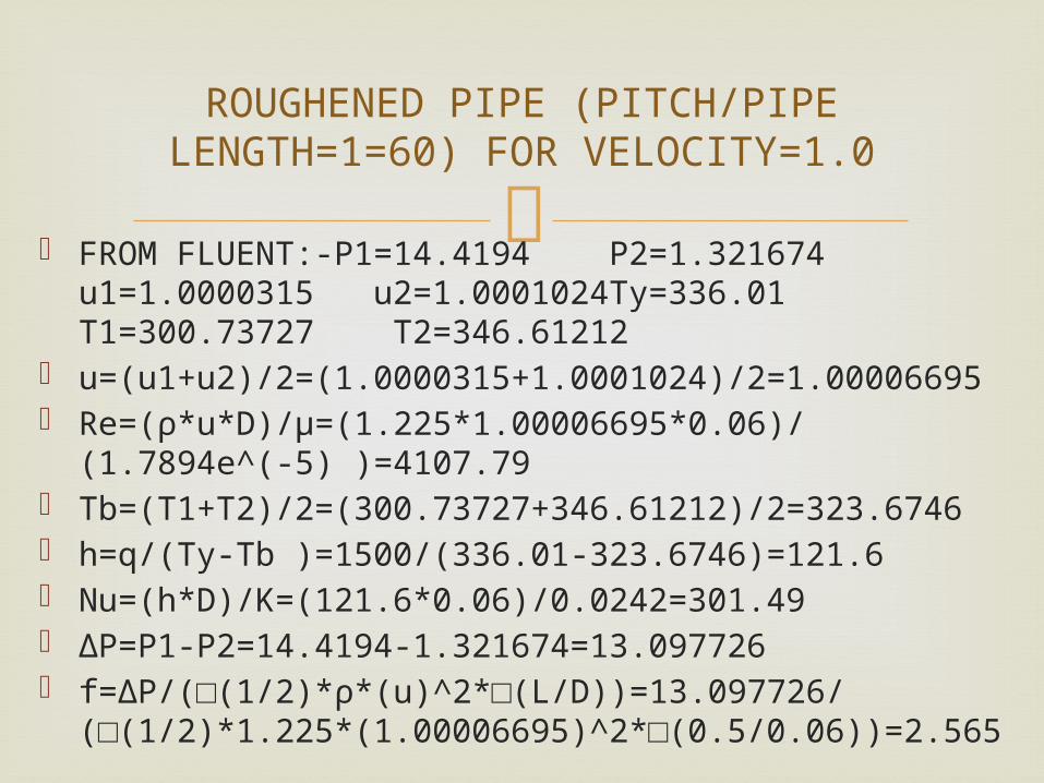
FROM FLUENT:-P1=14.4194 P2=1.321674 u1=1.0000315 u2=1.0001024Ty=336.01 T1=300.73727 T2=346.61212
u=(u1+u2)/2=(1.0000315+1.0001024)/2=1.00006695 Re=(ρ*u*D)/μ=(1.225*1.00006695*0.06)/(1.7894e^(-5)
)=4107.79 Tb=(T1+T2)/2=(300.73727+346.61212)/2=323.6746 h=q/(Ty-Tb )=1500/(336.01-323.6746)=121.6 Nu=(h*D)/K=(121.6*0.06)/0.0242=301.49 ∆P=P1-P2=14.4194-1.321674=13.097726 f=∆P/(□(1/2)*ρ*(u)^2*□(L/D))=13.097726/
(□(1/2)*1.225*(1.00006695)^2*□(0.5/0.06))=2.565
ROUGHENED PIPE (PITCH/PIPE LENGTH=1=60) FOR VELOCITY=1.0
U=0.5 U=1.0 U=1.5 U=2.0 U=2.5
Re 2053 4107.79 6162.21 8217.84 10273
Nu 292.8 301.49 281.721 285.6 301.227
f 5.263 2.565 1.675 1.43243 1.3199
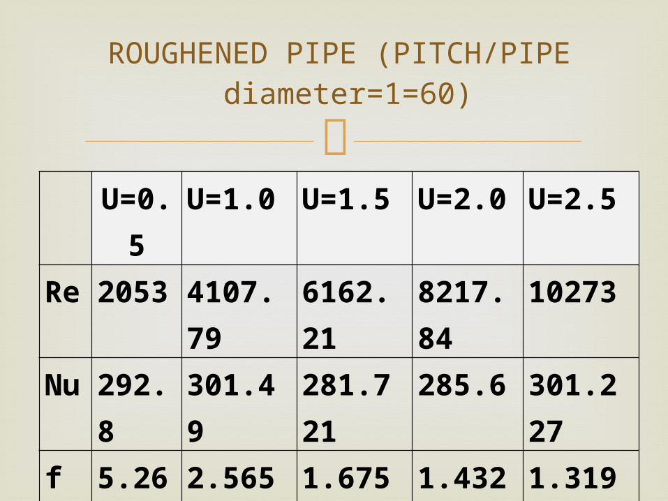
ROUGHENED PIPE (PITCH/PIPE diameter=1=60)
FROM FLUENT:-P1=5.0953159 P2=0.3721281 u1=0.53281337 u2=0.50563174 Ty=358.05173 T1=303.96246 T2=388.91751
u=(u1+u2)/2=(0.53281337+0.50563174)/2=0.519222555 Re=(ρ*u*D)/π=(1.225*0.519222555*0.06)/(1.7894e^(-
5) )=2132.718 T_B=(T1+T2)/2=(303.96246+388.91751)/2=346.439985 h=q/(Ty-Tb )=1500/(358.05173-346.439985)=129.17955 Nu=(h*D)/K=(129.17955*0.06)/0.0242=320.2798 ∆P=P1-P2=5.0953159-0.35721281=4.73810 f=∆P/(□(1/2)
ρ*(u)^2*□(L/D))=4.73810/(□(1/2)*1.225*(0.519222555)^2*□(0.5/0.06))=3.4432
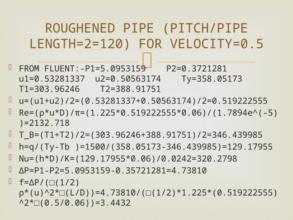
ROUGHENED PIPE (PITCH/PIPE LENGTH=2=120) FOR
VELOCITY=0.5
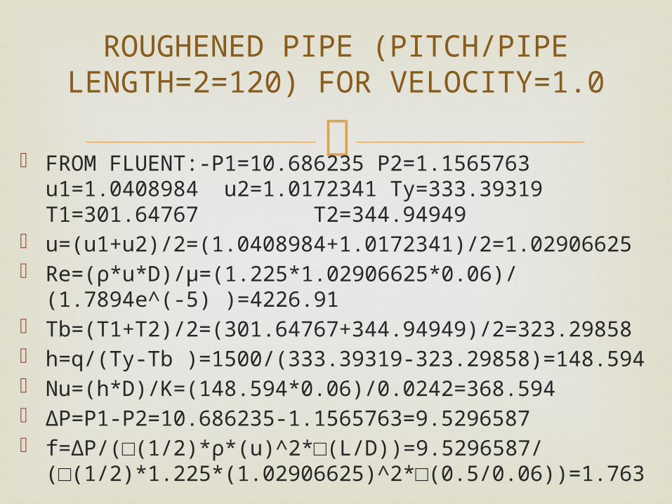
FROM FLUENT:-P1=10.686235 P2=1.1565763 u1=1.0408984 u2=1.0172341 Ty=333.39319 T1=301.64767 T2=344.94949
u=(u1+u2)/2=(1.0408984+1.0172341)/2=1.02906625 Re=(ρ*u*D)/μ=(1.225*1.02906625*0.06)/(1.7894e^(-
5) )=4226.91 Tb=(T1+T2)/2=(301.64767+344.94949)/2=323.29858 h=q/(Ty-Tb )=1500/(333.39319-323.29858)=148.594 Nu=(h*D)/K=(148.594*0.06)/0.0242=368.594 ∆P=P1-P2=10.686235-1.1565763=9.5296587 f=∆P/(□(1/2)*ρ*(u)^2*□(L/D))=9.5296587/
(□(1/2)*1.225*(1.02906625)^2*□(0.5/0.06))=1.763
ROUGHENED PIPE (PITCH/PIPE LENGTH=2=120) FOR
VELOCITY=1.0
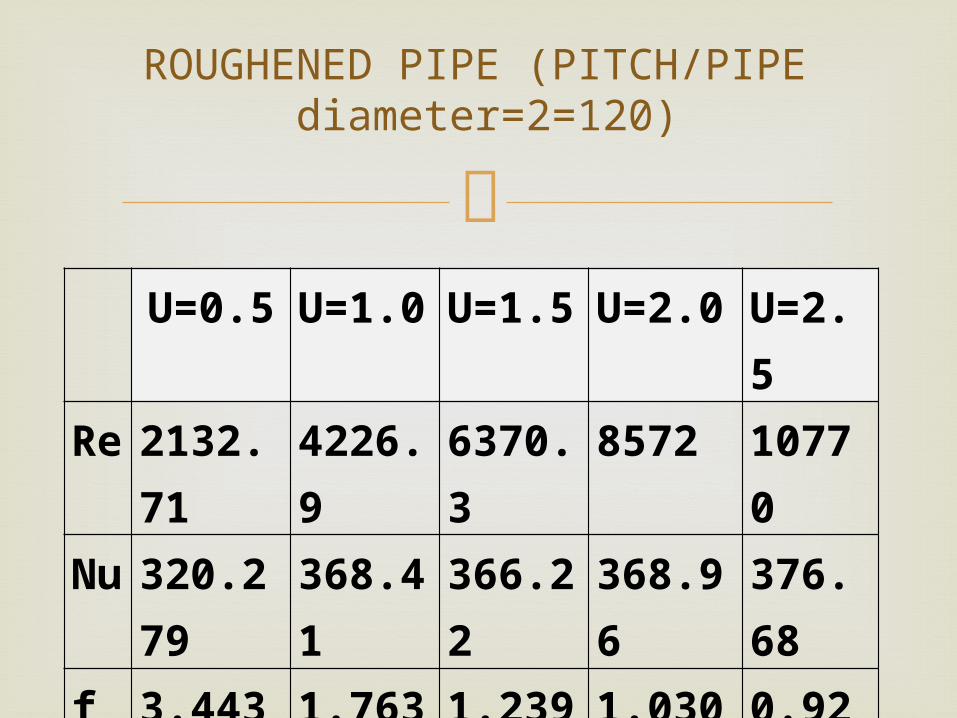
U=0.5 U=1.0 U=1.5 U=2.0 U=2.5
Re 2132.71 4226.9 6370.3 8572 10770
Nu 320.279 368.41 366.22 368.96 376.68
f 3.4432 1.763 1.2396 1.0306 0.9215
ROUGHENED PIPE (PITCH/PIPE diameter=2=120)
FROMFLUENT:-P1=3.43750 P2=0.45387 u1=0.50002003 u2=0.50008273 Ty=356.07758 T1=304.05145 T=385.88266
u=(u1+u2)/2=(0.50002003+0.50008273)/2=0.50005138 Re=(ρ*u*D)/μ=(1.225*0.50005138*0.06)/(1.7894e^(-
5) )=2053.97 Tb=(T1+T2)/2=(304.05145+385.88266)/2=344.967055 h=q/(Ty-Tb )=1500/(356.7758-344.967055)=131.8 Nu=(h*D)/K=(131.8*0.06)/0.0242=326.787 ∆P=P1-P2=3.4375029-0.45387191=2.98363099 f=∆P/(□(1/2)*ρ*(u)^2*□(L/D))=2.98363099/
(□(1/2)*1.225*(0.50005138)^2*□(0.5/0.06))=2.3377
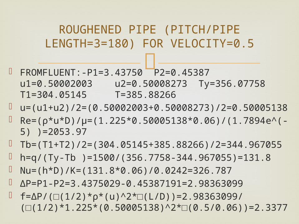
ROUGHENED PIPE (PITCH/PIPE LENGTH=3=180) FOR VELOCITY=0.5
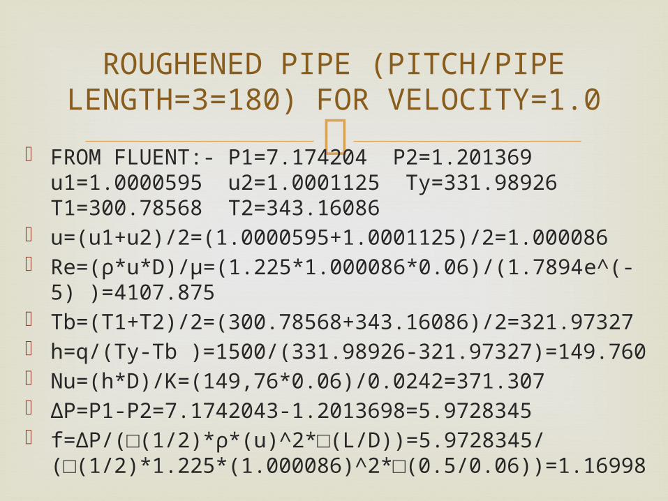
FROM FLUENT:- P1=7.174204 P2=1.201369 u1=1.0000595 u2=1.0001125 Ty=331.98926 T1=300.78568 T2=343.16086
u=(u1+u2)/2=(1.0000595+1.0001125)/2=1.000086 Re=(ρ*u*D)/μ=(1.225*1.000086*0.06)/(1.7894e^(-
5) )=4107.875 Tb=(T1+T2)/2=(300.78568+343.16086)/2=321.97327 h=q/(Ty-Tb )=1500/(331.98926-321.97327)=149.760 Nu=(h*D)/K=(149,76*0.06)/0.0242=371.307 ∆P=P1-P2=7.1742043-1.2013698=5.9728345 f=∆P/(□(1/2)*ρ*(u)^2*□(L/D))=5.9728345/
(□(1/2)*1.225*(1.000086)^2*□(0.5/0.06))=1.16998
ROUGHENED PIPE (PITCH/PIPE LENGTH=3=180) FOR
VELOCITY=1.0
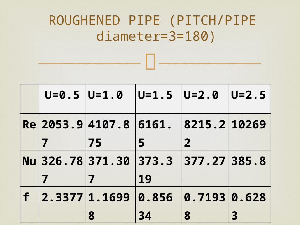
U=0.5 U=1.0 U=1.5 U=2.0 U=2.5
Re 2053.97 4107.875 6161.5 8215.22 10269
Nu 326.787 371.307 373.319 377.27 385.8
f 2.3377 1.16998 0.85634 0.71938 0.6283
ROUGHENED PIPE (PITCH/PIPE diameter=3=180)
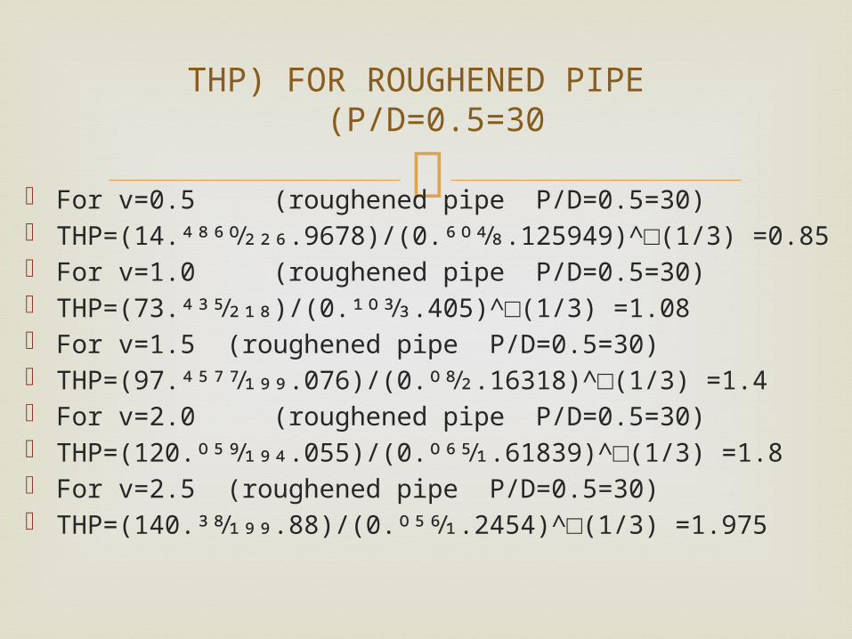
For v=0.5 (roughened pipe P/D=0.5=30) THP=(14.4860⁄226.9678)/(0.604⁄8.125949)^□(1/3)
=0.85 For v=1.0 (roughened pipe P/D=0.5=30) THP=(73.435⁄218)/(0.103⁄3.405)^□(1/3) =1.08 For v=1.5 (roughened pipe P/D=0.5=30) THP=(97.4577⁄199.076)/(0.08⁄2.16318)^□(1/3) =1.4 For v=2.0 (roughened pipe P/D=0.5=30) THP=(120.059⁄194.055)/(0.065⁄1.61839)^□(1/3) =1.8 For v=2.5 (roughened pipe P/D=0.5=30) THP=(140.38⁄199.88)/(0.056⁄1.2454)^□(1/3) =1.975
THP) FOR ROUGHENED PIPE P/D=0.5=30)
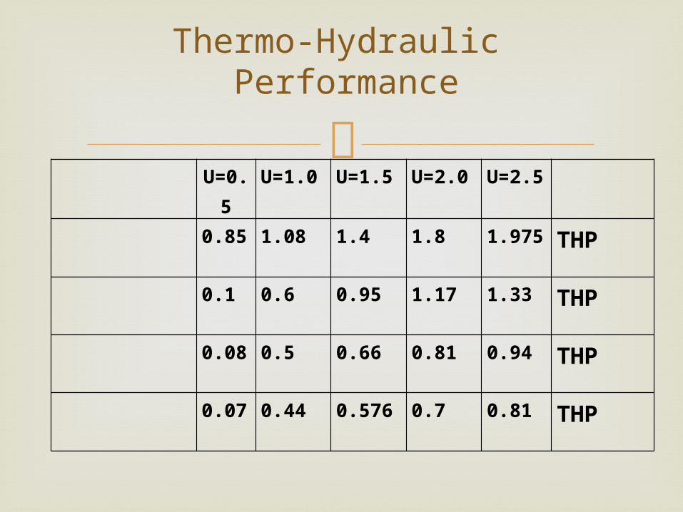
U=0.5 U=1.0 U=1.5 U=2.0 U=2.5
0.85 1.08 1.4 1.8 1.975 THP
0.1 0.6 0.95 1.17 1.33 THP
0.08 0.5 0.66 0.81 0.94 THP
0.07 0.44 0.576 0.7 0.81 THP
Thermo-Hydraulic Performance
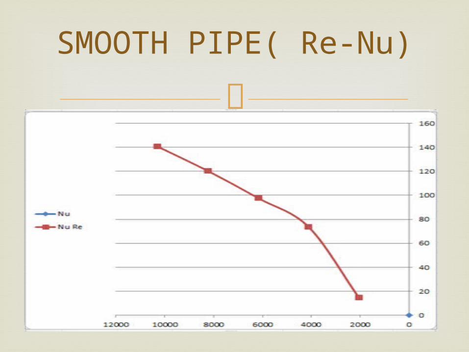
SMOOTH PIPE( Re-Nu)
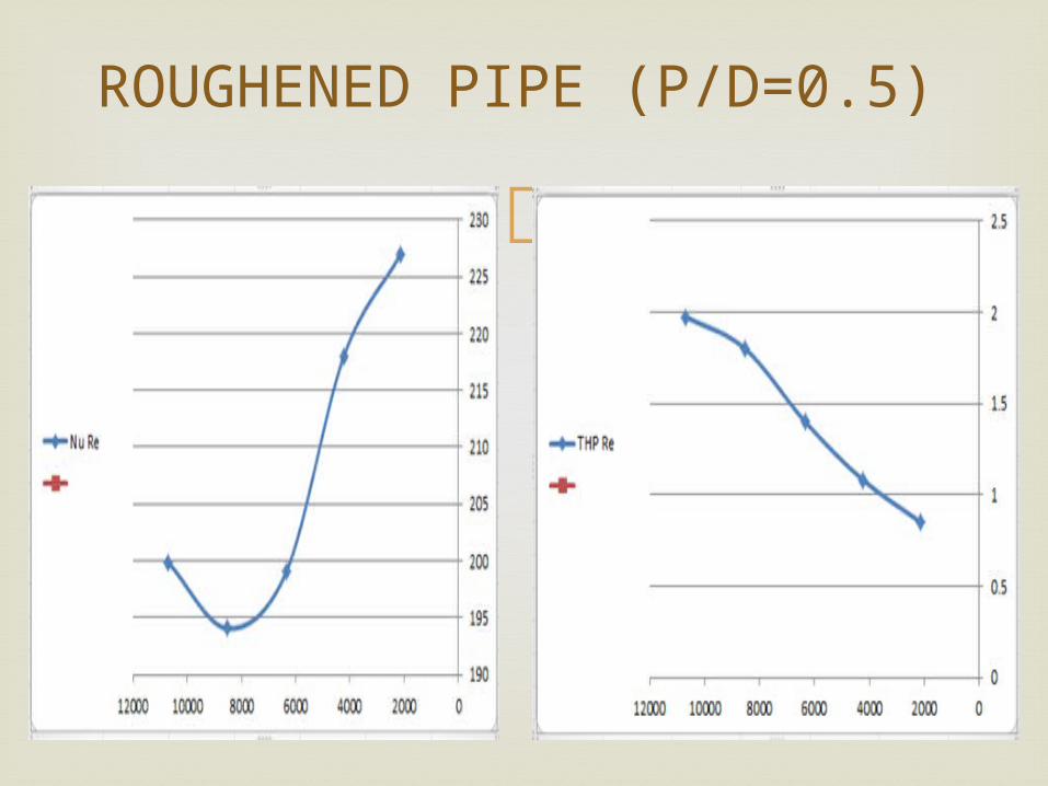
ROUGHENED PIPE (P/D=0.5)
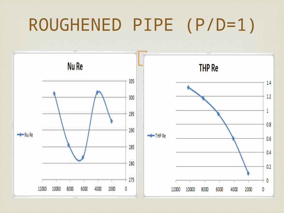
ROUGHENED PIPE (P/D=1)
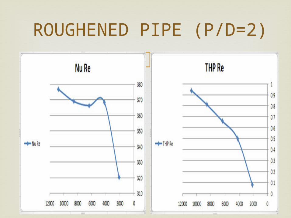
ROUGHENED PIPE (P/D=2)
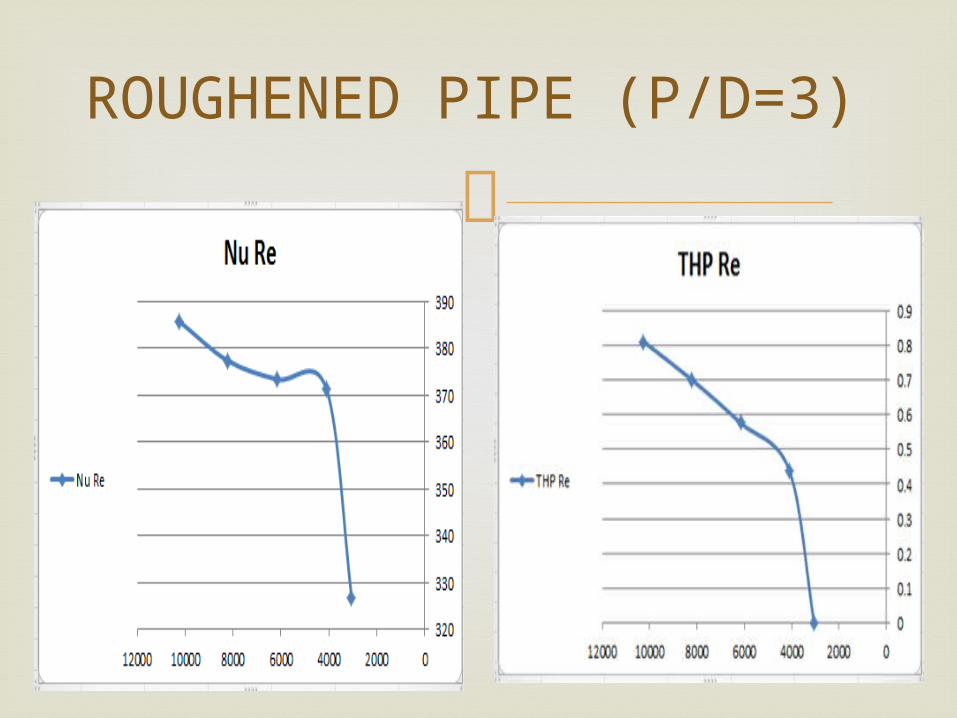
ROUGHENED PIPE (P/D=3)

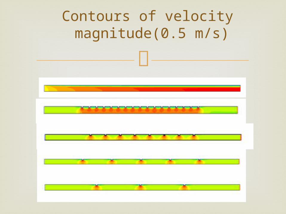
Contours of velocity magnitude(0.5 m/s)
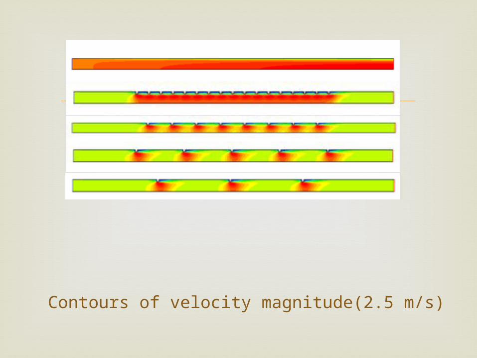
Contours of velocity magnitude(2.5 m/s)
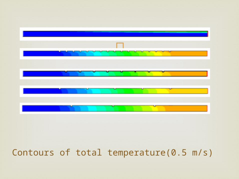
Contours of total temperature(0.5 m/s)

Contours of total temperature(2.5 m/s)
Heat transfer be better when we use
roughened pipe Increase in heat transfer companion with
increase in friction factor because of roughened surface
The results show that better heat transfer when the pitch/diameter is lower( (P/D)=0.5=30) and velocity=2.5
CONCLUSIONS

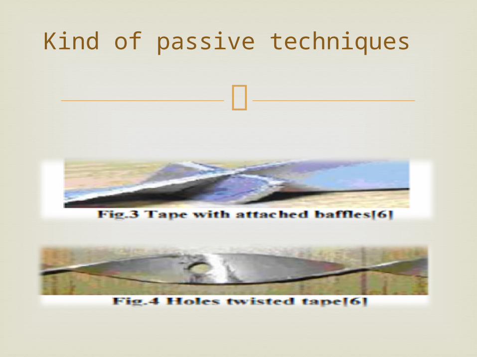
Kind of passive techniques
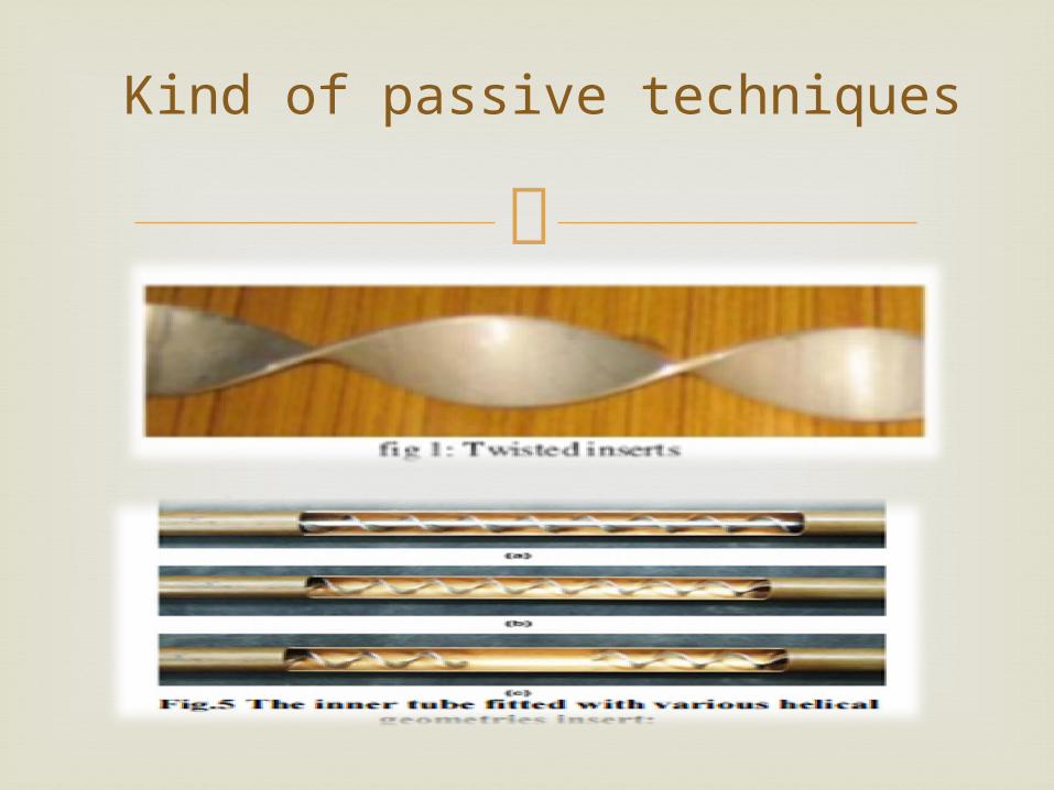
Kind of passive techniques
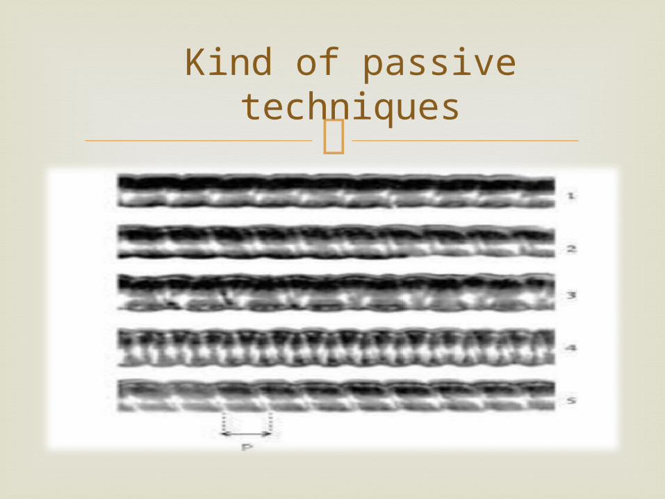
Kind of passive techniques
Kind of passive techniques

Augmentation of heat transfer, single phase(
www.thermopedia/content/574) Saunders, S.A.E “Heat Exchangers’’ John Wiley
& Sons, 2002.
reference