Embed Size (px)
Citation preview
Fundamentals of Heat Pipes
With Applications to Electronics Cooling
-- Widah Saied
Introduction
Things to be discussed: Basic components Advantages Ideal thermodynamic cycle Applications Types Heat transfer limitations Resistance network Wick design Choosing the working fluid Container design Heat pipes in electronics cooling Current research in electronics cooling
Basic Components
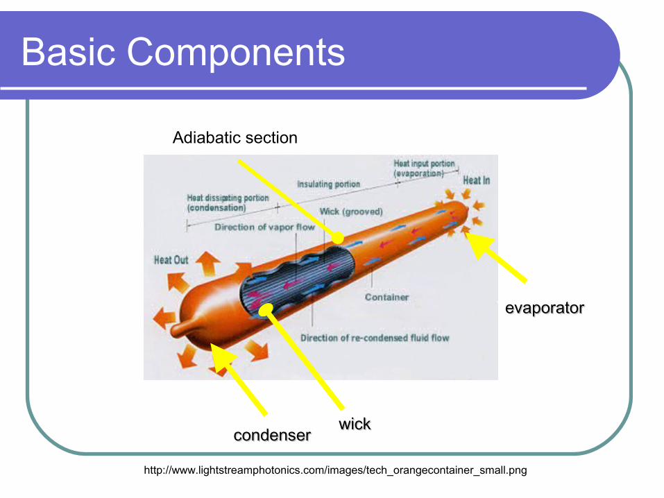
condensercondenser
evaporatorevaporator
wickwick
http://www.lightstreamphotonics.com/images/tech_orangecontainer_small.png
Adiabatic section
Advantages of Heat Pipes
Very high thermal conductivity. Less temperature difference needed to transport heat than traditional materials (thermal conductivity up to 90 times greater than copper for the same size) (Faghiri, 1995) resulting, in low thermal resistance. (Peterson,1994)
Power flattening. A constant condenser heat flux can be maintained while the evaporator experiences variable heat fluxes. (Faghiri, 1995)
Efficient transport of concentrated heat. (Faghiri, 1995)
Advantages of Heat Pipes
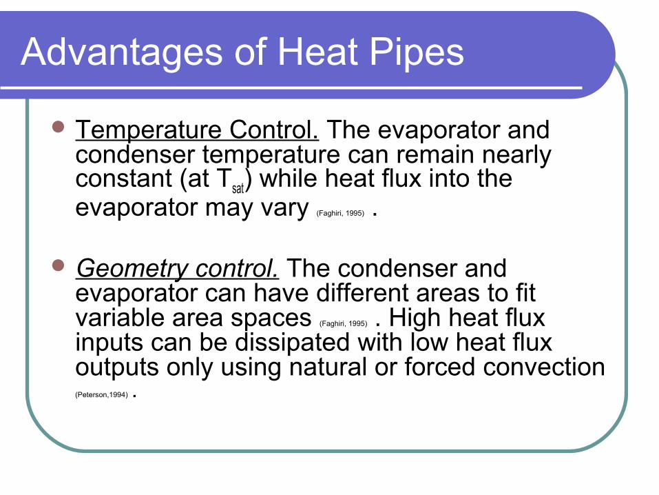
Temperature Control. The evaporator and condenser temperature can remain nearly constant (at Tsat) while heat flux into the evaporator may vary (Faghiri, 1995) .
Geometry control. The condenser and evaporator can have different areas to fit variable area spaces (Faghiri, 1995) . High heat flux inputs can be dissipated with low heat flux outputs only using natural or forced convection(Peterson,1994) .

Thermodynamic Cycle
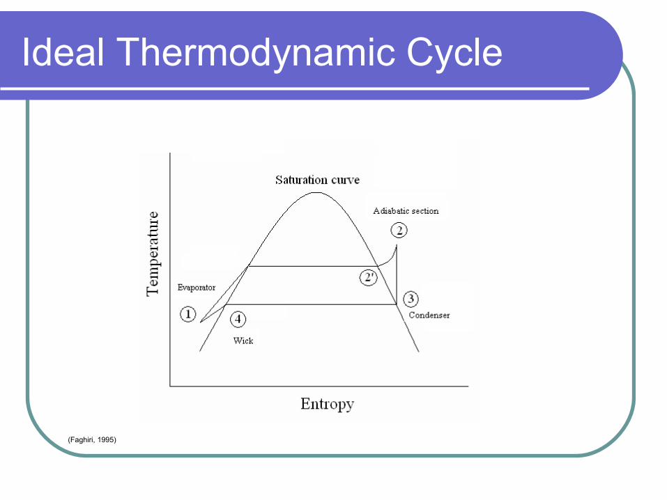
1-2 Heat applied to evaporator through external sources vaporizes working fluid to a saturated(2’) or superheated (2) vapor.
2-3 Vapor pressure drives vapor through adiabatic section to condenser.
3-4 Vapor condenses, releasing heat to a heat sink. 4-1 Capillary pressure created by menisci in wick
pumps condensed fluid into evaporator section. Process starts over.(Faghiri, 1995)
Ideal Thermodynamic Cycle
(Faghiri, 1995)
Heat Pipe Applications
Electronics cooling- small high performance components cause high heat fluxes and high heat dissipation demands. Used to cool transistors and high density semiconductors.
Aerospace- cool satellite solar array, as well as shuttle leading edge during reentry.
Heat exchangers- power industries use heat pipe heat exchangers as air heaters on boilers.
Other applications- production tools, medicine and human body temperature control, engines and automotive industry.
(Faghiri, 1995)
Types of Heat Pipes
Thermosyphon- gravity assisted wickless heat pipe. Gravity is used to force the condensate back into the evaporator. Therefore, condenser must be above the evaporator in a gravity field.
Leading edge- placed in the leading edge of hypersonic vehicles to cool high heat fluxes near the wing leading edge. (Faghiri, 1995)
Rotating and revolving- condensate returned to the evaporator through centrifugal force. No capillary wicks required. Used to cool turbine components and armatures for electric motors.
Cryogenic- low temperature heat pipe. Used to cool optical instruments in space. (Peterson, 1994)
Types of Heat Pipes
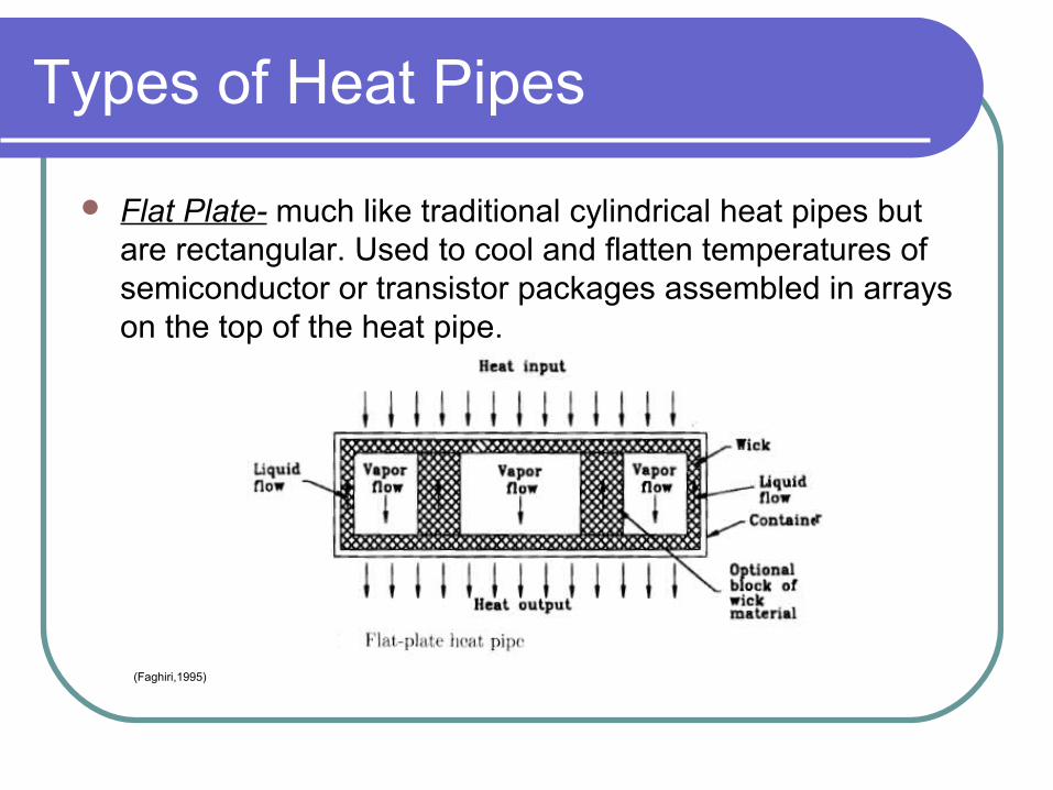
Flat Plate- much like traditional cylindrical heat pipes but are rectangular. Used to cool and flatten temperatures of semiconductor or transistor packages assembled in arrays on the top of the heat pipe.
(Faghiri,1995)
Types of Heat Pipes
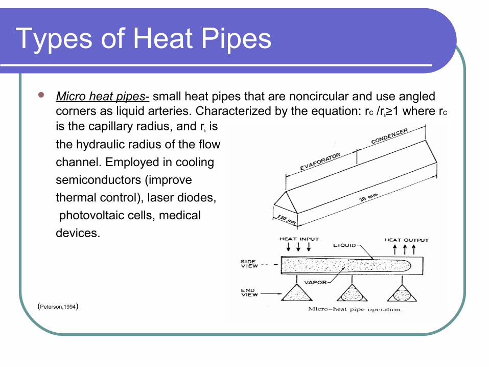
Micro heat pipes- small heat pipes that are noncircular and use angled corners as liquid arteries. Characterized by the equation: rc /rh≥1 where rc is the capillary radius, and rh is
the hydraulic radius of the flow
channel. Employed in cooling
semiconductors (improve
thermal control), laser diodes,
photovoltaic cells, medical
devices.
(Peterson,1994)
Types of Heat Pipes
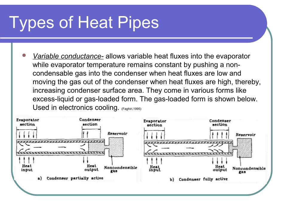
Variable conductance- allows variable heat fluxes into the evaporator while evaporator temperature remains constant by pushing a non- condensable gas into the condenser when heat fluxes are low and moving the gas out of the condenser when heat fluxes are high, thereby, increasing condenser surface area. They come in various forms like excess-liquid or gas-loaded form. The gas-loaded form is shown below. Used in electronics cooling. (Faghiri,1995)

Types of Heat Pipes
Capillary pumped loop heat pipe- for systems where the heat fluxes are very high or where the heat from the heat source needs to be moved far away. In the loop heat pipe, the vapor travels around in a loop where it condenses and returns to the evaporator. Used in electronics cooling.
(Faghiri, 1995)
Main Heat Transfer Limitations
Capillary limit- occurs when the capillary pressure is too low to provide enough liquid to the evaporator from the condenser. Leads to dryout in the evaporator. Dryout prevents the thermodynamic cycle from continuing and the heat pipe no longer functions properly.
Boiling Limit- occurs when the radial heat flux into the heat pipe causes the liquid in the wick to boil and evaporate causing dryout.
(Faghiri, 1995)
Heat Transfer Limitations
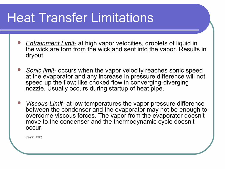
Entrainment Limit- at high vapor velocities, droplets of liquid in the wick are torn from the wick and sent into the vapor. Results in dryout.
Sonic limit- occurs when the vapor velocity reaches sonic speed at the evaporator and any increase in pressure difference will not speed up the flow; like choked flow in converging-diverging nozzle. Usually occurs during startup of heat pipe.
Viscous Limit- at low temperatures the vapor pressure difference between the condenser and the evaporator may not be enough to overcome viscous forces. The vapor from the evaporator doesn’t move to the condenser and the thermodynamic cycle doesn’t occur.(Faghiri, 1995)
Heat Transfer Limitations
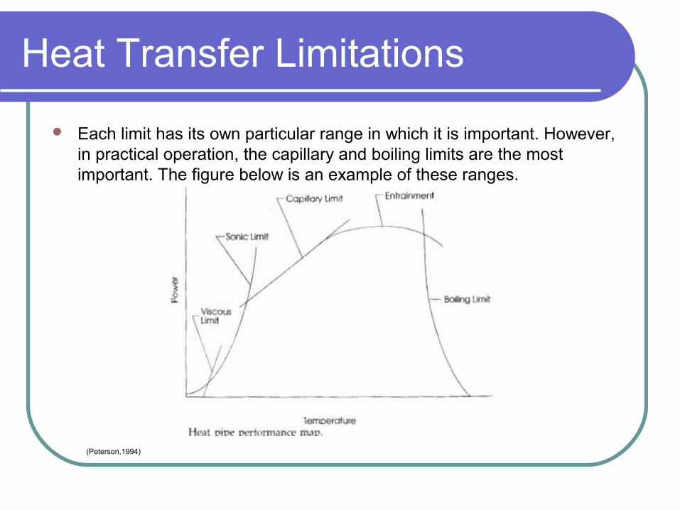
Each limit has its own particular range in which it is important. However, in practical operation, the capillary and boiling limits are the most important. The figure below is an example of these ranges.
(Peterson,1994)
Heat Transfer Limitations
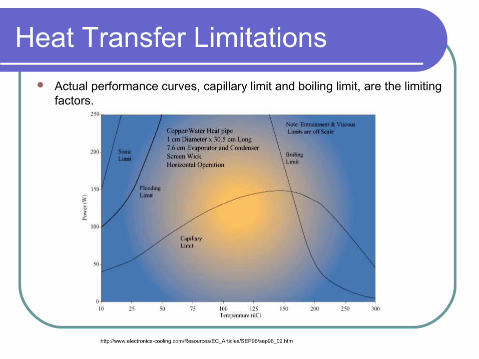
Actual performance curves, capillary limit and boiling limit, are the limiting factors.
http://www.electronics-cooling.com/Resources/EC_Articles/SEP96/sep96_02.htm
Capillary Limit
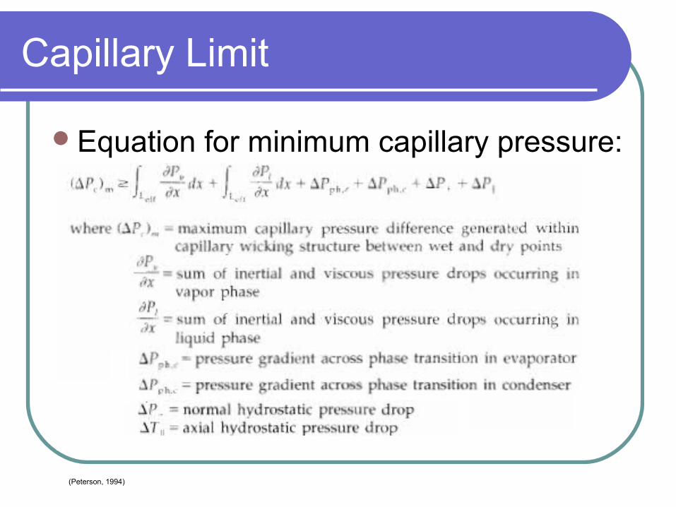
For a heat pipe to function properly, the capillary pressure must be greater or equal to the sum of the pressure drops due to inertial, viscous, and hydrostatic forces, as well as, pressure gradients.
If it is not, then the working fluid is not supplied rapidly enough to the evaporator to compensate for the liquid loss through vaporization. If this occurs, there is dryout in the evaporator.
(Peterson, 1994)
Capillary Limit
Equation for minimum capillary pressure:
(Peterson, 1994)
Boiling Limit
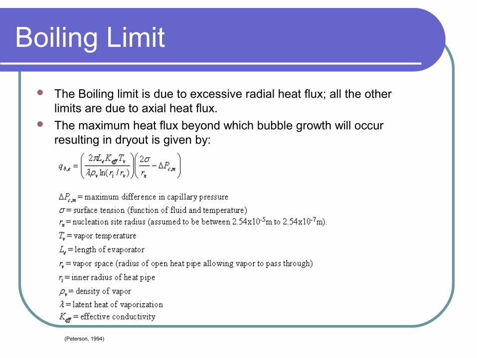
The Boiling limit is due to excessive radial heat flux; all the other limits are due to axial heat flux.
The maximum heat flux beyond which bubble growth will occur resulting in dryout is given by:
(Peterson, 1994)

Boiling Limit
Keff given by the table below:
Kl=therm. cond. Liquid, kw=therm. cond. wick δ =thickness of tube, ε =wick porosity
Resistance Network
(Peterson, 1994)
Heat Pipe Resistance
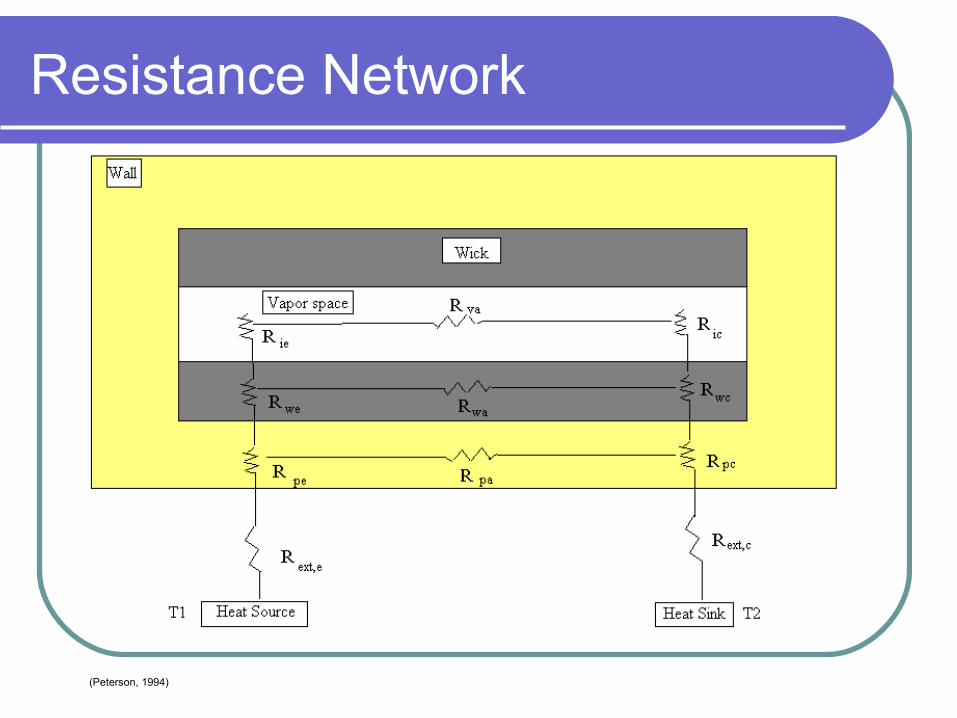
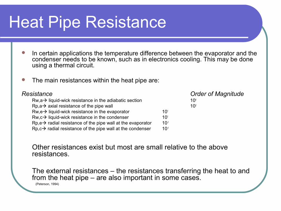
In certain applications the temperature difference between the evaporator and the condenser needs to be known, such as in electronics cooling. This may be done using a thermal circuit.
The main resistances within the heat pipe are:
Resistance Order of MagnitudeRw,a liquid-wick resistance in the adiabatic section 104
Rp,a axial resistance of the pipe wall 102
Rw,e liquid-wick resistance in the evaporator 101
Rw,c liquid-wick resistance in the condenser 101
Rp,e radial resistance of the pipe wall at the evaporator 10-1
Rp,c radial resistance of the pipe wall at the condenser 10-1
Other resistances exist but most are small relative to the above resistances.
The external resistances – the resistances transferring the heat to and from the heat pipe – are also important in some cases.
(Peterson, 1994)
Heat Pipe Resistance
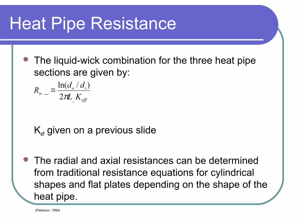
The liquid-wick combination for the three heat pipe sections are given by:
Keff given on a previous slide
The radial and axial resistances can be determined from traditional resistance equations for cylindrical shapes and flat plates depending on the shape of the heat pipe.
eff
iow KL
ddR
_2
)/ln(_
π=
(Peterson, 1994)
The Wick and its Design
Main Purpose- provides structure and force that transports the condensate liquid back to the evaporator. Also, ensures working fluid is evenly distributed over evaporator surface.
(Peterson, 1994)
Capillary Pressure
The driving force that transports the condensed working liquid through the wick to the evaporator is provided by capillary pressure. Working fluids that are employed in heat pipes have concave facing menisci (wetting liquids) as opposed to convex facing menisci (non wetting liquids).
Contact angle is defined as the angle between the solid and vapor regions. Wetting fluids have angles between 0 and 90 degrees. Non wetting fluids have angles between 90 and 180 degrees.(Faghiri, 1995)
Capillary Pressure
http://cwx.prenhall.com/petrucci/medialib/media_portfolio/text_images/FG13_04.JPGhttp://cwx.prenhall.com/petrucci/medialib/media_portfolio/text_images/FG13_04.JPG
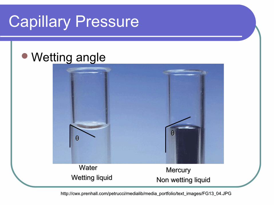
WaterWaterWetting liquidWetting liquid
MercuryMercuryNon wetting liquidNon wetting liquid
θθθθ
Wetting angle
Capillary Pressure
The shape of a fluid’s meniscus is dependent on the fluid’s surface tension and the solid-fluid adhesion force. If the adhesion force is greater than the surface tension, the liquid near the solid will be forced up and the surface tension of the liquid will keep the surface intact causing the entire liquid to move up. http://hyperphysics.phy-astr.gsu.edu/hbase/hframe.html
When the liquid in the evaporator vaporizes, the radius of curvature of the menisci in the wick decreases. As the vapor condenses in the condenser, the radius of curvature of the menisci in the wick increases. The difference in the radius of curvature results in capillary pressure (Peterson,1994) . Capillary pressure is also due to body forces and phase-change interactions (Faghiri, 1995).
Capillary Pressure
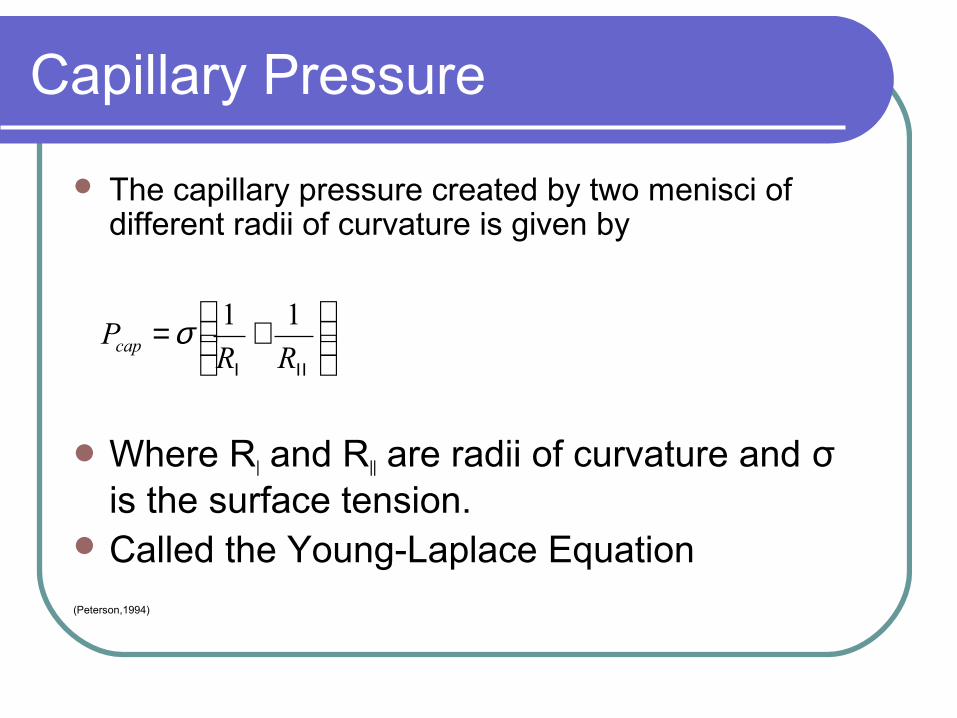
The capillary pressure created by two menisci of different radii of curvature is given by
Where RI and RII are radii of curvature and σ is the surface tension.
Called the Young-Laplace Equation
(Peterson,1994)
+=
ΙΙΙ RRPcap
11σ
Capillary Pressure
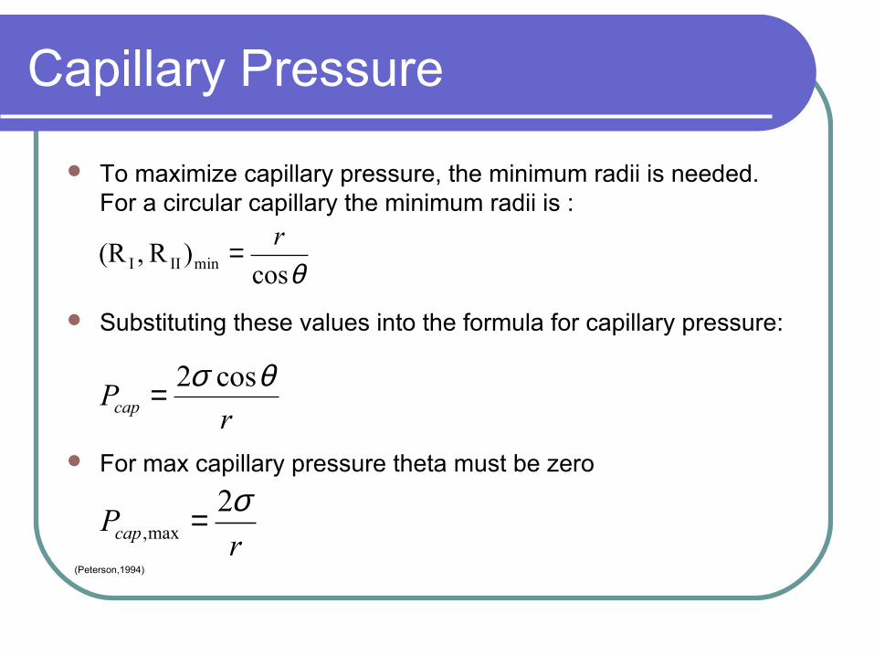
To maximize capillary pressure, the minimum radii is needed. For a circular capillary the minimum radii is :
Substituting these values into the formula for capillary pressure:
For max capillary pressure theta must be zero
θcos)R ,(R minIII
r=
rPcap
σ2max, =
rPcap
θσ cos2=
(Peterson,1994)
Capillary Pressure
Wetting fluids have a cosθ value that will be positive. This results in a positive capillary pressure that creates a pushing force on the liquid in the wick near the condenser; this forces the liquid to move to the evaporator.
Non-wetting fluids will have cosθ values that are negative, resulting in a negative capillary pressure that creates a suction force on the liquid in the wick. The liquid is prevented from moving to the evaporator.
For this reason, the working liquid in heat pipes must be a wetting liquid.
(Peterson,1994)
Wick Design
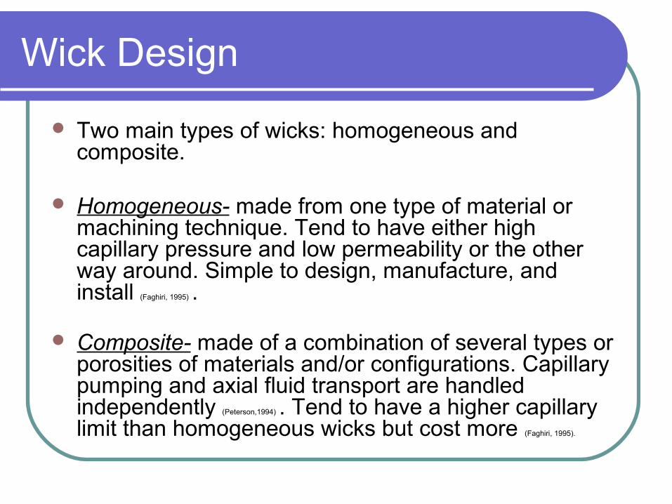
Two main types of wicks: homogeneous and composite.
Homogeneous- made from one type of material or machining technique. Tend to have either high capillary pressure and low permeability or the other way around. Simple to design, manufacture, and install (Faghiri, 1995) .
Composite- made of a combination of several types or porosities of materials and/or configurations. Capillary pumping and axial fluid transport are handled independently (Peterson,1994) . Tend to have a higher capillary limit than homogeneous wicks but cost more (Faghiri, 1995).
Wick Design
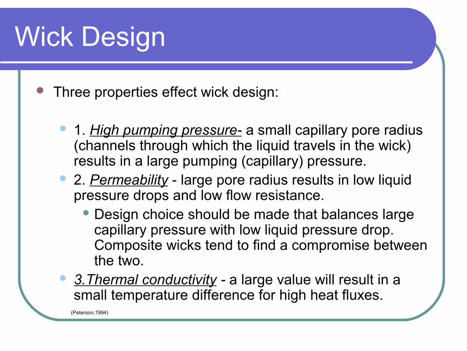
Three properties effect wick design:
1. High pumping pressure- a small capillary pore radius (channels through which the liquid travels in the wick) results in a large pumping (capillary) pressure.
2. Permeability - large pore radius results in low liquid pressure drops and low flow resistance.
Design choice should be made that balances large capillary pressure with low liquid pressure drop. Composite wicks tend to find a compromise between the two.
3.Thermal conductivity - a large value will result in a small temperature difference for high heat fluxes.
(Peterson,1994)
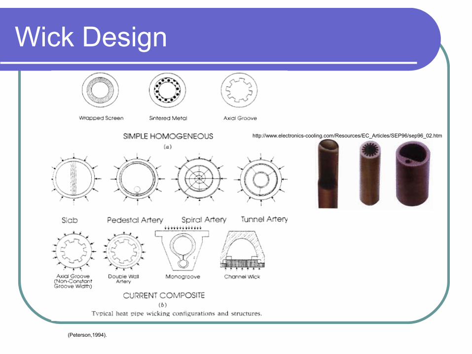
Wick Design
(Peterson,1994).
http://www.electronics-cooling.com/Resources/EC_Articles/SEP96/sep96_02.htm
Choosing the Working Fluid
Heat pipes work on a cycle of vaporization and condensation of the working fluid, which results in the heat pipe’s high thermal conductivity. When choosing a working fluid for a heat pipe, the fluid must be able to operate within the heat pipe’s operating temperature range. For instance, if the operating temperatures are too high, the fluid may not be able to condense. However, if the operating temperatures are too low the fluid will not be able to evaporate. Watch the saturation temperature for your desired fluid at the desired heat pipe internal pressure.
In addition, the working fluid must be compatible with the wick and container material.
(Peterson, 1994).
Choosing the Working Fluid
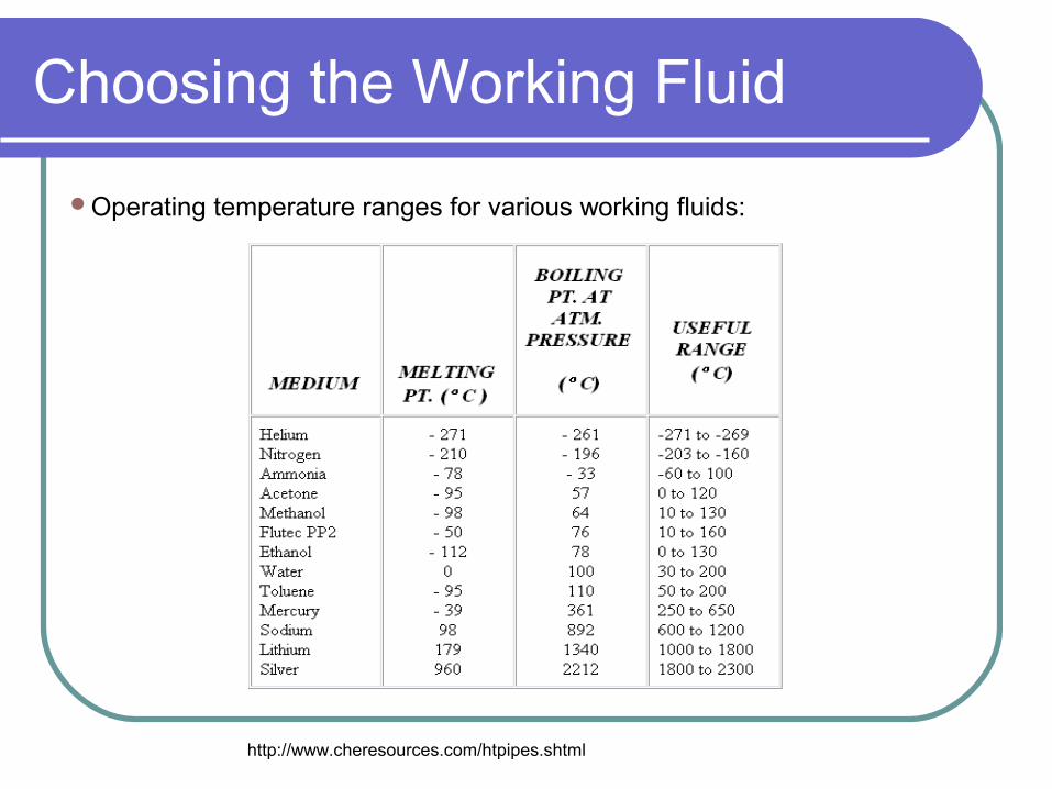
Operating temperature ranges for various working fluids:
http://www.cheresources.com/htpipes.shtml

Choosing the Working Fluid
Generally, as the operating temperature range of the working fluid increases, the heat transport capability increases.
Choice of working fluid should also incorporate the fluid’s interactions with the heat pipe container and wick.
(Peterson, 1994).
Choosing the Working Fluid
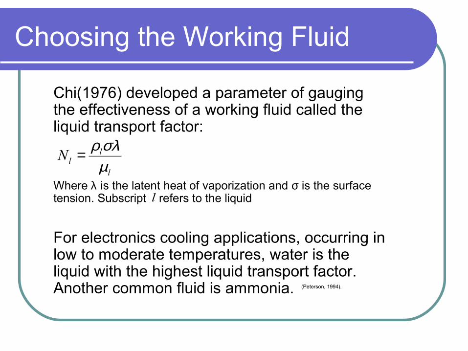
Chi(1976) developed a parameter of gauging the effectiveness of a working fluid called the liquid transport factor:
Where λ is the latent heat of vaporization and σ is the surface tension. Subscript refers to the liquid
For electronics cooling applications, occurring in low to moderate temperatures, water is the liquid with the highest liquid transport factor. Another common fluid is ammonia.
l
llN µ
σλρ=
l
(Peterson, 1994).
Container Design
Things that should be considered for container design: Operating temperature range of the heat pipe. Internal operating pressure and container structural
integrity. Evaporator and condenser size and shape. Possibility of external corrosion. Prevent leaks. Compatibility with wick and working fluid.
(peterson,1994)
Container Design
Stresses:Since the heat pipe is like a pressure vessel
it must satisfy ASME pressure vessel codes.
Typically the maximum allowable stress at any given temperature can only be one-fourth of the material’s maximum tensile strength.
(peterson, 1994)
Container Design
Typical materials:AluminumStainless steel CopperComposite materials High temperature heat pipes may use
refractory materials or linings to prevent corrosion.
(Peterson, 1994)
Heat pipe Compatibility
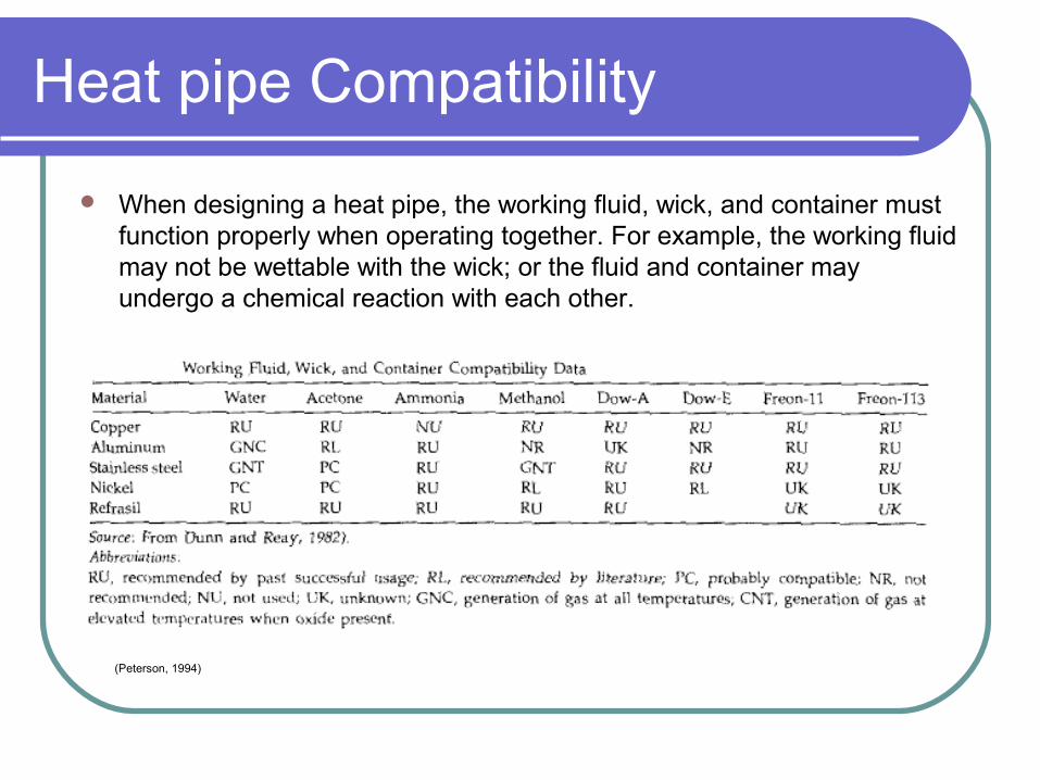
When designing a heat pipe, the working fluid, wick, and container must function properly when operating together. For example, the working fluid may not be wettable with the wick; or the fluid and container may undergo a chemical reaction with each other.
(Peterson, 1994)
Heat pipe Compatibility
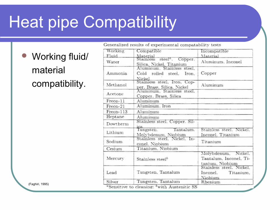
Working fluid/
material
compatibility.
(Faghiri, 1995)
Heat Sink/Source Interface
The contact resistance between the evaporator and the heat source and between the condenser and the heat sink is relatively large and should be minimized.
Methods used to join the parts include use of thermally conductive adhesives, as well as, brazed, or soldered techniques.
(Peterson, 1994)
Heat Pipes in Electronics Cooling
Cooling of electronics has one primary goal: maintain a component’s temperatures at or below the manufacturer’s maximum allowable temperature. As the temperature of an electronic part increases the rate of failure increases.
(Peterson, 1994)
Heat Pipes in Electronics Cooling
Heat pipes are excellent candidates for electronics cooling because of their high thermal conductivity, high heat transfer characteristics, they provide constant evaporator temperatures with variable heat fluxes, and variable evaporator and condenser sizes.
Therefore, they are good alternatives to large heat sinks, especially in laptops where space is limited.
They are good alternative to air cooling because of their better heat transport capabilities. Air cooling may still be used to remove heat from the condenser.
(Peterson, 1994).
Heat Pipes in Electronics Cooling
Common heat pipes used in electronics cooling: Micro heat pipes Capillary looped heat pipes Flat plate heat pipes Variable conductance heat pipes
Heat Pipes in Electronics Cooling
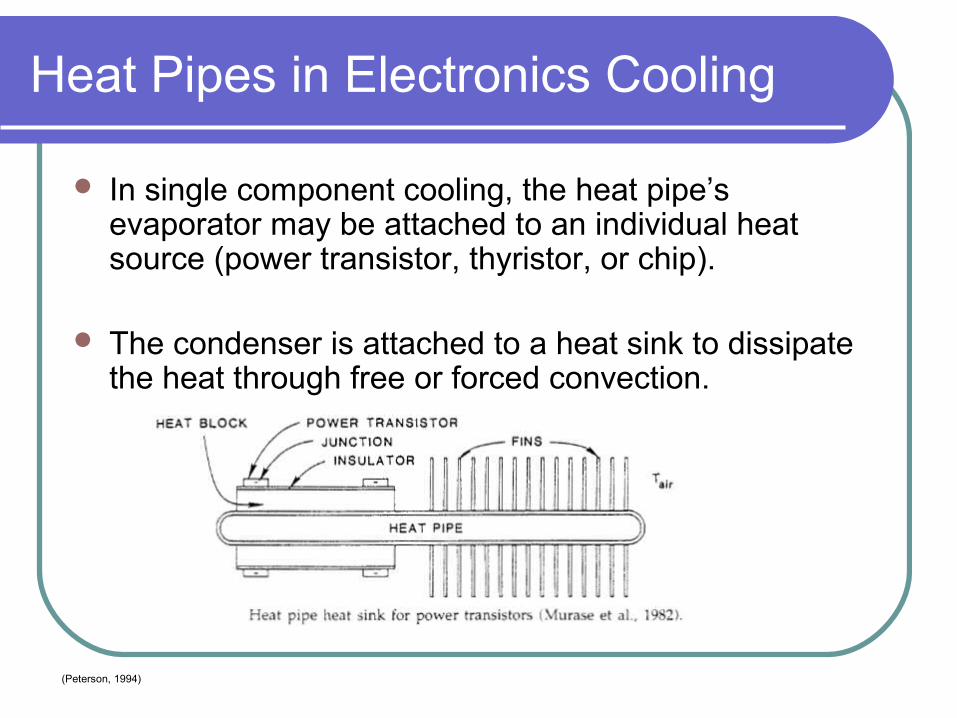
In single component cooling, the heat pipe’s evaporator may be attached to an individual heat source (power transistor, thyristor, or chip).
The condenser is attached to a heat sink to dissipate the heat through free or forced convection.
(Peterson, 1994)
Heat Pipes in Electronics Cooling
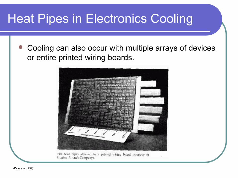
Cooling can also occur with multiple arrays of devices or entire printed wiring boards.
(Peterson, 1994)

Heat Pipes in Electronics Cooling
An arrayed heat pipe cooling system
(Peterson, 1994)
Heat Pipes in Electronics Cooling
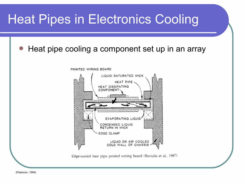
Heat pipe cooling a component set up in an array
(Peterson, 1994)
Heat Pipes in Electronics Cooling
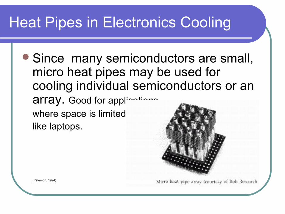
Since many semiconductors are small, micro heat pipes may be used for cooling individual semiconductors or an array. Good for applications
where space is limited like laptops.
(Peterson, 1994)
Heat Pipes in Electronics Cooling
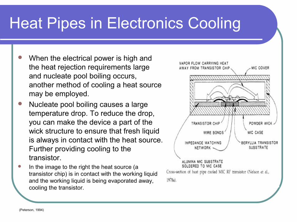
When the electrical power is high and the heat rejection requirements large and nucleate pool boiling occurs, another method of cooling a heat source may be employed.
Nucleate pool boiling causes a large temperature drop. To reduce the drop, you can make the device a part of the wick structure to ensure that fresh liquid is always in contact with the heat source. Further providing cooling to the transistor.
In the image to the right the heat source (a transistor chip) is in contact with the working liquid and the working liquid is being evaporated away, cooling the transistor.
(Peterson, 1994)
Heat Pipes in Electronics Cooling
Summary:Heat pipes enable devices with higher
density heat dissipation requirements and greater reliability.
Low costProven alternative to conventional methods
of electronics cooling.
(Peterson, 1994)
Current Research in Electronics Cooling
Laptops today perform well and are small; therefore, they have high heat dissipation demands.
Excess heat may slow down the processor’s speed or shut the laptop off. (Junnarkar, 2003)
First time a heat pipe used in a laptop was in 1994. Current heat pipes move the heat from the CPU to a small heat sink. (Ali et al., 1999)
Current Research in Electronics Cooling
Because micro heat pipes are small they are very useful in cooling of laptops where space is highly restricted.
Wang and Peterson (2003) have come up with two different micro heat pipe setups for laptop cooling: Micro heat pipes configured into flat plate shapes were
employed to cool a CPU. The condenser was attached to a heat sink. The heat sink was smaller in size than one not attached to a heat pipe because the base of the heat sink attached to a heat pipe experiences more uniform temperatures and therefore, an increased efficiency.
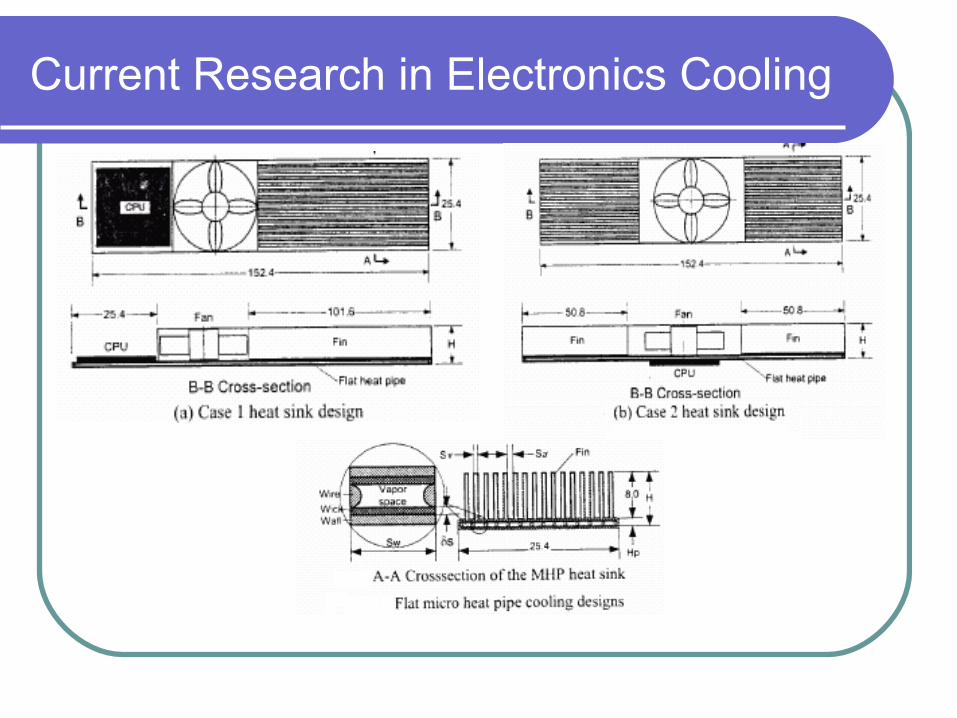
Current Research in Electronics Cooling
Two different configurations were developed Both were 152.4 mm long and 25.4 mm wide Layers of copper screen mesh, with parallel wires and
two copper sheets were formed, in the shape of a flat heat pipe, to form an enclosed space.
No capillary wick structure needed because of the micro heat pipe’s sharp corners.
The fan is strategically placed to provide forced convection to the heat sink.
Current Research in Electronics Cooling
Current Research in Electronics Cooling
Main Results:In configuration 1, tilt angle effected the
amount of heat dissipated In configuration 2, tilt angle had no effect
on amount dissipated.Important because laptops experience
operation in many orientations.
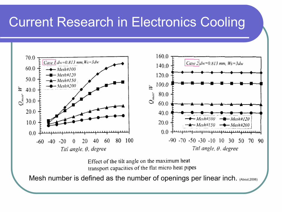
Current Research in Electronics Cooling
Mesh number is defined as the number of openings per linear inch. (About,2006)
Current Research in Electronics Cooling
Things that increased heat transport capacity: Increasing mesh number Increasing wire diameter
Current Research in Electronics Cooling
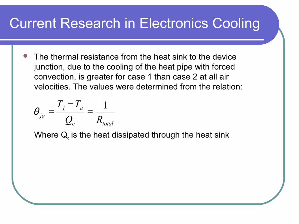
The thermal resistance from the heat sink to the device junction, due to the cooling of the heat pipe with forced convection, is greater for case 1 than case 2 at all air velocities. The values were determined from the relation:
Where Qc is the heat dissipated through the heat sink
totalc
ajja RQ
TT 1=−
=θ

Current Research in Electronics Cooling
Current Research in Electronics Cooling
Other discoveries:Within the CPU’s operating temperature
limit, the heat capacity of a micro heat pipe is restricted by the heat sink’s ability to transfer heat through convection
Heat transfer not restricted by the capillary limit.
Current Research in Electronics Cooling
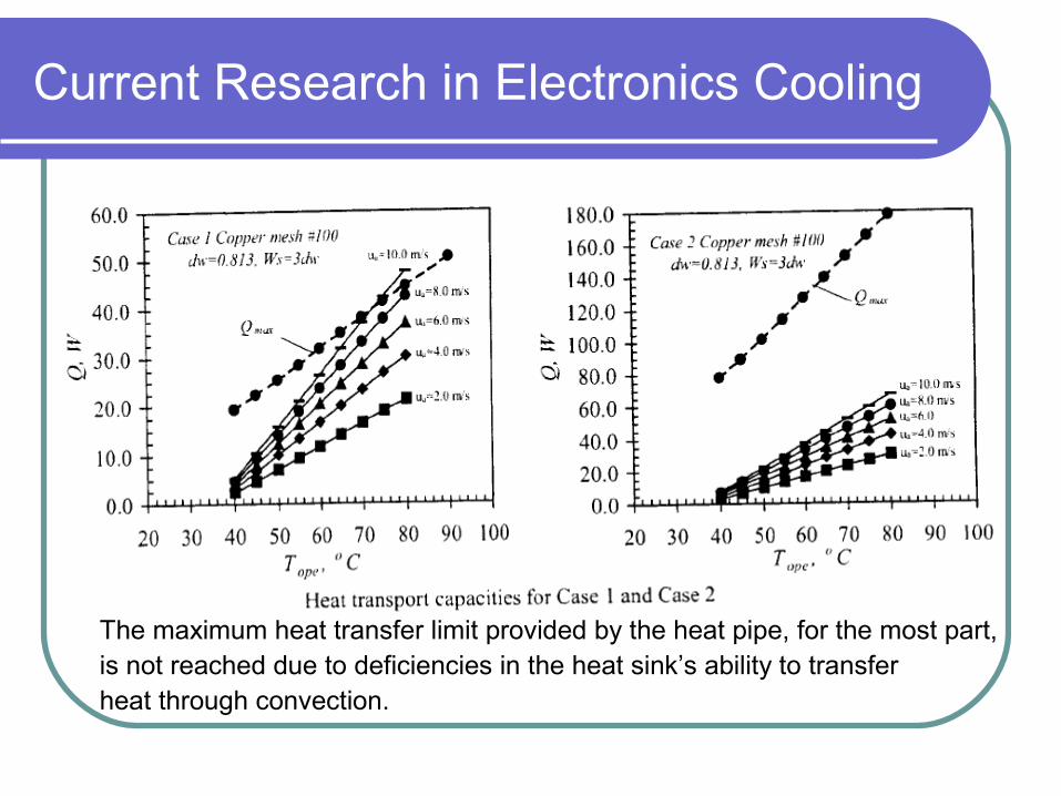
The maximum heat transfer limit provided by the heat pipe, for the most part,is not reached due to deficiencies in the heat sink’s ability to transfer heat through convection.
Current Research in Electronics Cooling
Case 2 provided a lower thermal resistance and a greater heat transport capacity than Case 1.
Case 2 transported 52W at 85°C and .85 °C /W resistance. Case 1 transported 24W at 85°C and 1.55 °C /W resistance.
References About, Inc. (2006). May 2006. http://composite.about.com/library/glossary/m/bldef-m3304.htm Ali, A., Dehoff, R., and Grubb, K., 1999. ”Advanced Heat Pipe Thermal Solutions For Higher Power Notebook
Computers”. Basilius, A., Tanzer, H., and McCabe, S., 1987 “Heat Pipes for Cooling of High Density Printed Wiring Boards,” Proc. 6 th
Int. Heat Pipe Conf., Grenoble, France, pp.531-536. The Chemical Engineer’s Resource Page. 2004. March 2006. http://www.cheresources.com/htpipes.shtml Chi, 1976, Heat Pipe Theory and Practice, McGraw-Hill, New York. Dunn, P.D., and Reay, D.A., 1982, HJeat Pipes, 3rd.ed., Pergamon, Oxford. Faghri, Amin, 1995. Heat Pipe Science and Technology. US: Taylor &Francis Junnarkar, Sandeep. “Laptops Cool off with ‘Smart’ Heat Pipes.” Cnet News.com. January22, 2003. March 2006. Lightstream Photonics (2003). March 2006.
http://www.lightstreamphotonics.com/images/tech_orangecontainer_small.png Murase, T., Yoshida, K., Koizumi, T., and Ishida, N., 1982, “Heat Pipe Heat Sink ‘Heat Kicker’ for Cooling of Semi-
Conductors,” Furukama Review, Tokyo, Japan, Vol.2, pp24-33. Nave, R. Hyperphysics -capillary action. 2006. March 2006. http://hyperphysics.phy-astr.gsu.edu/hbase/hframe.html Nelson, L., Sekhon, K., and Fritz, J. E., 1978, “ Direct Heat Pipe Cooling of Semiconductor Devices,” Proc. 3 rd Int. Heat
Pipe Conf., Palo Alto, CA, pp373-376. Peterson, G.P., 1994. An Introduction to Heat Pipes. Canada: John Wiley & Sons, Inc. Petrucci, R.H., Harwood, W.S., Herring, G. General Chemisty Principles and Modern Applications. 2001, Prentice-Hall,
Inc. Compainion Website. Narayan S. Homane. March 2006. http://cwx.prenhall.com/petrucci/medialib/media_portfolio/text_images/FG13_04.JPG
Warner, S. (2006) May 2006. http://www.electronics-cooling.com/Resources/EC_Articles/SEP96/sep96_02.htm Wang, Y., and Peterson, G., 2003. “ Flat Heat Pipe Cooling Devices for Mobile Computers.” ASME International
Mechanical Engineering Congress, Washington, D.C., Nov. 15-21,2003. Zorbil, V., Stulc, P., and Polasek, F., 1988, “ Enhancement Cooling of the Boards with Integrated Circuits by Heat
Pipes, “ Proc. 3rd. Int. Heat Pipe Symp., Tsukuba, Japan, pp273-279.


![Fundamentalsof!Nanotransistors! - edXPurdueX+nano530x+T12016... · 2015-12-11 · Mark Lundstrom Purdue University December, 2015 [1] Supriyo Datta, Lessons from Nanoelectronics:](https://img.pdfslide.us/doc/110x75/5e802b5da7b17d73ec5b7eda/fundamentalsofnanotransistors-edx-purduexnano530xt12016-2015-12-11.jpg)