Embed Size (px)
Citation preview
Functional Safety Frequency-to-DCTransmitter with Display
SFY
Page 1
The SFY installs quickly and easily in harsh conditions using our protective fi eld-mount enclosures, or on a surface, DIN-rail or relay track.
December 2016
DescriptionThe SFY Functional Safety SIL 3 capable Frequency-to-DC Transmitter with Display is part of Moore Industries’ FS Functional Safety Series. It monitors frequency, period, high or low pulse width, and contact closure signals and converts the input signal to a proportional, input-to-output isolated 4-20mA output ready for direct interface with a Safety System, readout instrument, recorder, PLC, DCS, SCADA system. The 2-wire (loop-powered) SFY is ideal for use in your Safety Instrumented System (SIS) in a wide range of process and factory automation monitoring applications:
• Turbine Tachometer Generators
• Turbine Flow Meters
• Magnetic Pickups • Dry Contact Closures
• Variable Frequency Drives • Rotating Equipment
• Pulse and Frequency Output Transducers
• Motor and Conveyor Speed
Features• exida certifi ed to IEC 61508:2010. Certifi ed by exida
to IEC 61508 for systematic integrity up to SIL 3 and for random integrity up to SIL 2. This means that an SFY is approved for single use in Safety Instrumented Systems (SIS) up to SIL 2 and in a redundant architecture (1oo2, 2oo3, etc.) up to SIL 3.
• Comprehensive FMEDA certifi ed safety data. Upon request, exida-certifi ed FMEDA data is available for a functional safety practitioner to use in determining the SFY’s applicability in specifi c safety-related applications.
• Exceptional accuracy and long-term stability. Typical accuracy is ±0.025% of span with up to 5 years between scheduled calibrations.
• Sets up in minutes with PC software. You can choose, and then view to confi rm, all application-specifi c operating parameters.
• Versatile input choices. Measures frequency ranges between an amazingly low 0.005Hz up to 25kHz; periods from 40microseconds to 200sec; and pulse widths from 0.2msec to 200 seconds.
• Programmable moving average fi lter. Minimizes measurement instability caused by the eff ects of bent turbine blades and other frequency variations.
• User-confi gurable display. A 5-digit LCD shows the process variable in selectable engineering units.
• Input-to-output isolated and RFI/EMI protected. Resistant to unpredictable ground loops and the harmful eff ects of plant and equipment “noise”.
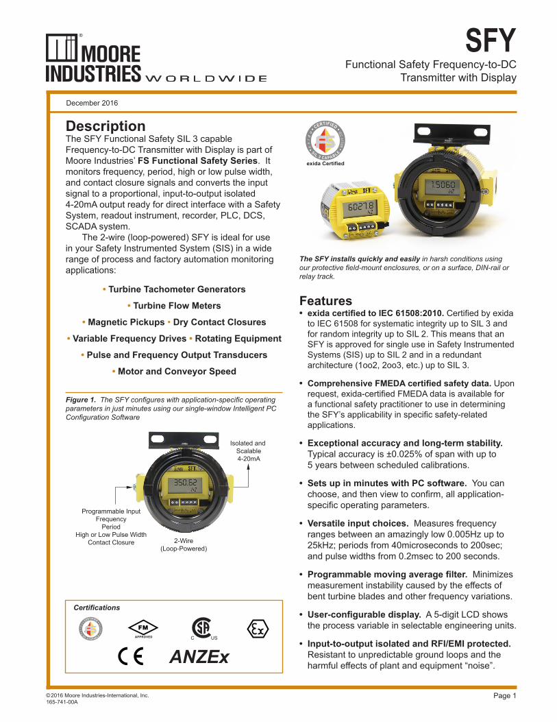
Figure 1. The SFY confi gures with application-specifi c operating parameters in just minutes using our single-window Intelligent PC Confi guration Software
©2016 Moore Industries-International, Inc.165-741-00A
Programmable InputFrequency
PeriodHigh or Low Pulse Width
Contact Closure
Isolated and Scalable4-20mA
2-Wire(Loop-Powered)
Certifi cations
Functional Safety Frequency-to-DCTransmitter with Display
SFY
Page 2
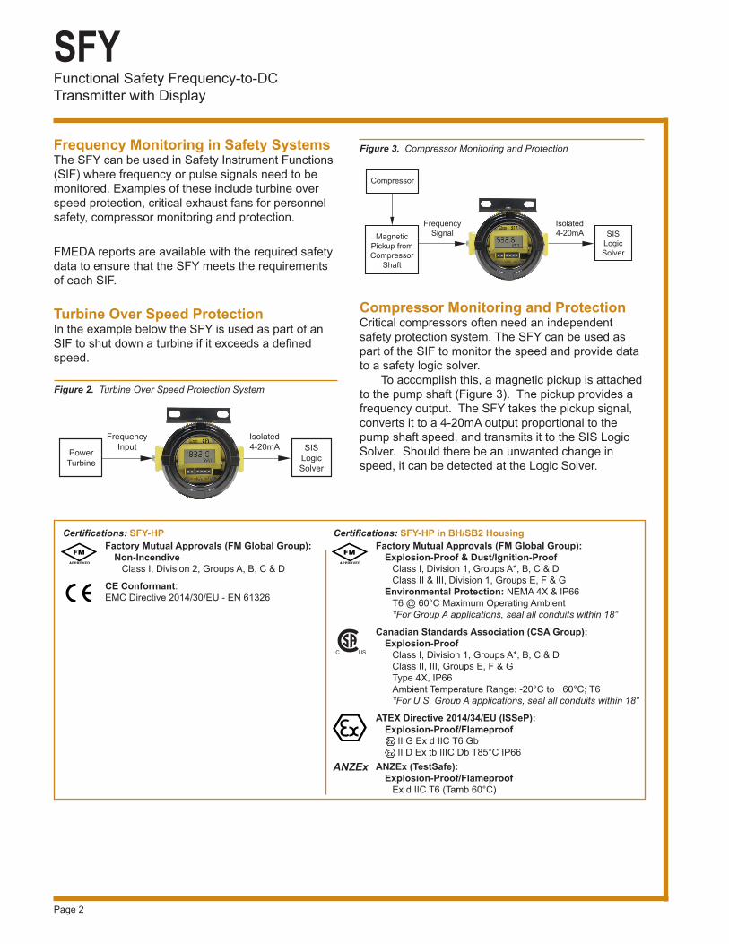
Compressor Monitoring and ProtectionCritical compressors often need an independent safety protection system. The SFY can be used as part of the SIF to monitor the speed and provide data to a safety logic solver. To accomplish this, a magnetic pickup is attached to the pump shaft (Figure 3). The pickup provides a frequency output. The SFY takes the pickup signal, converts it to a 4-20mA output proportional to the pump shaft speed, and transmits it to the SIS Logic Solver. Should there be an unwanted change in speed, it can be detected at the Logic Solver.
Frequency Monitoring in Safety SystemsThe SFY can be used in Safety Instrument Functions (SIF) where frequency or pulse signals need to be monitored. Examples of these include turbine over speed protection, critical exhaust fans for personnel safety, compressor monitoring and protection.
FMEDA reports are available with the required safety data to ensure that the SFY meets the requirements of each SIF.
Turbine Over Speed ProtectionIn the example below the SFY is used as part of an SIF to shut down a turbine if it exceeds a defi ned speed.
Figure 2. Turbine Over Speed Protection System
FrequencyInput
Isolated4-20mA SIS
LogicSolver
PowerTurbine
FrequencySignal
Isolated4-20mA SIS
LogicSolver
MagneticPickup fromCompressor
Shaft
Compressor
Figure 3. Compressor Monitoring and Protection
Factory Mutual Approvals (FM Global Group): Non-Incendive Class I, Division 2, Groups A, B, C & D
CE Conformant:EMC Directive 2014/30/EU - EN 61326
Certifi cations: SFY-HPFactory Mutual Approvals (FM Global Group): Explosion-Proof & Dust/Ignition-Proof Class I, Division 1, Groups A*, B, C & D Class II & III, Division 1, Groups E, F & G Environmental Protection: NEMA 4X & IP66 T6 @ 60°C Maximum Operating Ambient *For Group A applications, seal all conduits within 18”
Canadian Standards Association (CSA Group): Explosion-Proof Class I, Division 1, Groups A*, B, C & D Class II, III, Groups E, F & G Type 4X, IP66 Ambient Temperature Range: -20°C to +60°C; T6 *For U.S. Group A applications, seal all conduits within 18” ATEX Directive 2014/34/EU (ISSeP): Explosion-Proof/Flameproof II G Ex d IIC T6 Gb II D Ex tb IIIC Db T85°C IP66ANZEx (TestSafe): Explosion-Proof/Flameproof Ex d IIC T6 (Tamb 60°C)
Certifi cations: SFY-HP in BH/SB2 Housing
Functional Safety Frequency-to-DCTransmitter with Display
SFY
Page 3
804-030-26 Fuse Protected, Non-Isolated USB Communication Cable
Performance Display(Continued)
Performance(Continued)
Specifi cationsInput Accuracy: See Tables 1-7Output Accuracy: ±0.015% of spanOverall Accuracy: The overall accuracy of the unit is the combined input and output accuracies. It includes the combined eff ects of linearity, hys-teresis, repeatability, and adjustment resolution. Does not include ambient temperature eff ect.Input Hysteresis: See Tables 5-7Input Threshold: See Tables 5-7Stability: See Table 1Minimum Frequency: Twice the lower rangeDigital Input Filter: 3dB point is at 10kHzStep Response Time: 300msec maximum, 200msec typical from the time an input is applied to the output reaching 90% of its fi nal value + actual inputRise Time: 100msec maximum for the output to change from 10% to 90% of its scale of an input step change of 0% to 100% + actual inputIsolation: 500Vrms between input, output, and case continuous, and will withstand a 500Vac dielec-tric strength test for one minute with no breakdownRipple: 10mV p-p mea-sured across a 250 ohm resistorOvercurrent Limiting: 25mA maximumMaximum Voltages: 48Vdc output, maxi-mum; DC input, 48Vdc,
maximum; AC input, 30Vac maximum for 0.02-30AC model, 250Vac maximum for 10-250AC modelInput Impedance: >30kohms for DC and con-tact closure inputs; 2kohms for input >6V, 4kohms typical@50Hz and 56kohms typical@1kHz for input <6V for 0.02-30AC model; >125kohms for 10-250AC modelLoad Capability: 508 ohms@24V
Output Current Limiting: 3.8mA and 21.4mA for input under range and over range; 3.6mA and 23.6mA for input failureLoad Eff ect (current outputs): Negligible within specifi ed power limitsPower Supply Eff ect: ±0.002% of span per 1V changeStartup Time: Performance within specifi cation less than 1sec after power is applied for frequency higher than 100Hz and average of 8 samplesDamping: Adjustable from 0 to 30 seconds with PC softwareLinearization: Confi gurable up to 128 points with PC softwareMoving Average: Confi gurable up to 16 seg-ments with PC software Low Pass Filter: On/Off is software confi gurableType: LCD; Top Row, 10.16mm (0.4 in) high black digits on a refl ective
background; Bottom Row, 5.72mm (0.225 in) high black digits on a refl ective backgroundDisplay Update Rate: 100msecFormat: Top row is fi ve alphanumeric characters, plus sign and decimal point; bottom is fi ve alpha-numeric charactersRange: -99999 to 99999Minimum Display Span: 1.00
Operating & Storage Range: -40°C to +85°C (-40°F to +185°F)Relative Humidity: 0-95%, non-condensingAmbient Temperature Eff ect: Input to output, ±0.007% of span/°C maximum; Digital Accu-racy, ±0.003% of span/°C maximumRFI/EMI Immunity: 20V/m@ 80-1000MHz, 1kHz AM, when tested according to IEC61000-4-3Noise Rejection: Common mode, 120dB typical@100mVp-p input
SFY HP: 227 grams (5.3 ounces)SFY in BH housing with glass cover: 1451 grams (3 pounds, 12.4 ounces)
Display
Ambient Conditions
Weight
Supply Voltage – 12V
0.0236A= Ohms
AccessoriesEach SFY order comes with one copy of our Intelligent PC Confi guration Software (Windows® compatible) on CD. 750-75E05-01 Intelligent PC Confi guration Software
803-039-26 Isolated Confi guration Cable (9-pin Serial Port)
Non-Isolated Confi guration Cable (9-pin Serial Port)803-040-26
Part Number Part
To order additional software or cables:
Functional Safety Frequency-to-DCTransmitter with Display
SFY
Page 4
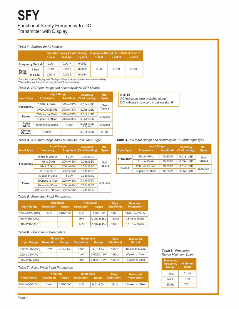
Table 4. AC Input Range and Accuracy for 10-250V Input Type
Input Type
Frequency
Period
Frequency
0.5Hz to 25kHz
1Hz to 5kHz
1Hz to 25kHz
10Hz to 5kHz
40μsec to 2sec
200μsec to 1sec
40μsec to 50sec
200μsec to 100msec
Amplitude
1-30V
200mV-30V
200mV-30V
20mV-30V
1-30V
200mV-30V
200mV-30V
20mV-30V
Accuracy (% of Reading)
0.05±1LSD
0.01±1LSD
0.05±1LSD
0.01±1LSD
0.05±1LSD
0.01±1LSD
0.05±1LSD
0.01±1LSD
Input Range Min. Span
See Table 8
500μsec
Input Type
Frequency
Period
Frequency
1Hz to 5kHz
1Hz to 25kHz
200μsec to 1sec
40μsec to 50sec
Amplitude
10-250V
10-250V
10-250V
10-250V
Accuracy (% of reading)
0.01±1LSD
0.05±1LSD
0.01±1LSD
0.05±1LSD
Input Range Min.Span
See Table 8
500μsec
Table 3. AC Input Range and Accuracy for PRG Input Type
Input Range
100mV-30V (DC)
20mV-30V (AC)
10V-250V(AC)
Resolution
1mV
Range
0.01-2.5V
Threshold
Table 5. Frequency Input Parameters
Resolution
1mV
1mV
1mV
Range
0.01-1.5V
0.002-0.15V
0.002-0.15V
Hysteresis Measured Frequency
0.02Hz to 25kHz
0.5Hz to 25kHz
0.5Hz to 25kHz
Input Range
100mV-30V (DC)
20mV-30V (AC)
10V-250V (AC)
Resolution
1mV
Range
0.01-2.5V
Threshold Filter(3db Point)
10kHz
10kHz
10kHz
Table 6. Period Input Parameters
Range
0.01-1.5V
0.002-0.15V
0.002-0.15V
Hysteresis MeasuredPeriod
40μsec to 50sec
40μsec to 2sec
40μsec to 2sec
Input Range
100mV-30V (DC)
Resolution
1mV
Range
0.01-2.5V
Threshold Filter(3db Point)
10kHz
Table 7. Pulse Width Input Parameters
Resolution
1mV
Hysteresis MeasuredPulse Width
0.2msec to 50sec
Range
0.01-1.5V
Maximum Frequency
Range
10Hz
5kHz
25kHz
Minimum Span
0.1Hz
1Hz
25Hz
Table 8. Frequency Range Minimum Span
Frequency
0.02Hz to 5kHz
0.02Hz to 25kHz
200μsec to 50sec
40μsec to 50sec
0.5msec to 50sec
<20Hz
Amplitude
100mV-30V
200mV-30V
100mV-30V
200mV-30V
1-30V
Accuracy (% of reading)
0.01±1LSD
0.05±1LSD0.01±1LSD
0.05±1LSD
0.05±1LSD±2μsec
0.01±1LSD
Input Range Min. Span
See Table 8
500μsec
500μsec
0.1Hz
Table 2. DC Input Range and Accuracy for All SFY Models
Frequency/Period
1 Sec
0.1 Sec
1 year
0.001
0.001
0.0015
3 years
0.0017
0.0017
0.0026
Input-to-Display (% of Reading)
Table 1. Stability for All Models*
5 years
0.0022
0.0022
0.0034
Display-to-Output (% of Output Span**)1 year
0.08
3 years
0.139
5 years
0.179
*Combine Input-to-Display and Display-to-Output values to determine overall stability.**Consult factory for improved long-term drift specifi cations.
PulseWidth
Filter(3db Point)
10kHz
10kHz
10kHz
NOTE: AC indicates zero-crossing signal.DC indicates non-zero crossing signal.
Resolution
1mV
1mV
1mV
Input Type
Frequency
Period
Pulse Width
Contact Closure
Functional Safety Frequency-to-DCTransmitter with Display
SFY
Page 5
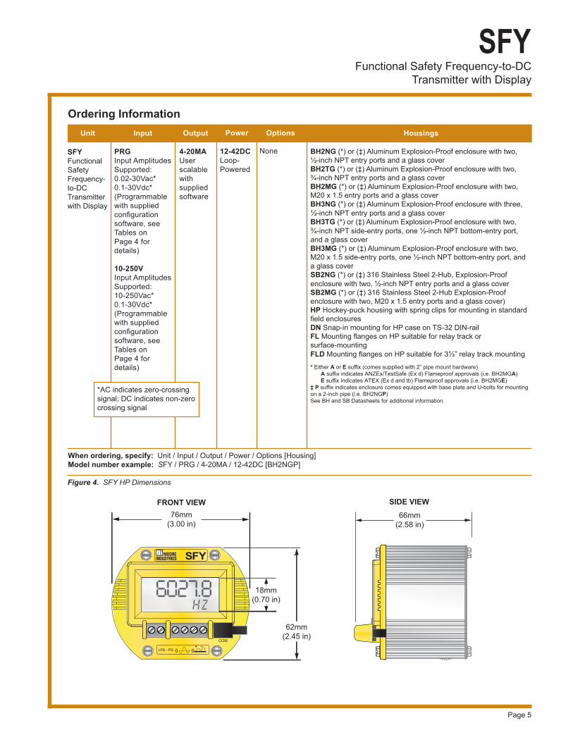
Ordering InformationUnit
SFYFunctional Safety Frequency-to-DC Transmitter with Display
When ordering, specify: Unit / Input / Output / Power / Options [Housing] Model number example: SFY / PRG / 4-20MA / 12-42DC [BH2NGP]
*AC indicates zero-crossing signal; DC indicates non-zero crossing signal
Input
PRGInput Amplitudes Supported: 0.02-30Vac*0.1-30Vdc*(Programmable with supplied confi guration software, see Tables onPage 4 for details)
10-250VInput Amplitudes Supported:10-250Vac*0.1-30Vdc* (Programmable with supplied confi guration software, see Tables onPage 4 for details)
Output
4-20MA User scalable with supplied software
Options
None
Power
12-42DCLoop-Powered
Housings
BH2NG (*) or (‡) Aluminum Explosion-Proof enclosure with two, ½-inch NPT entry ports and a glass coverBH2TG (*) or (‡) Aluminum Explosion-Proof enclosure with two, ¾-inch NPT entry ports and a glass coverBH2MG (*) or (‡) Aluminum Explosion-Proof enclosure with two, M20 x 1.5 entry ports and a glass coverBH3NG (*) or (‡) Aluminum Explosion-Proof enclosure with three, ½-inch NPT entry ports and a glass coverBH3TG (*) or (‡) Aluminum Explosion-Proof enclosure with two, ¾-inch NPT side-entry ports, one ½-inch NPT bottom-entry port, and a glass coverBH3MG (*) or (‡) Aluminum Explosion-Proof enclosure with two, M20 x 1.5 side-entry ports, one ½-inch NPT bottom-entry port, and a glass coverSB2NG (*) or (‡) 316 Stainless Steel 2-Hub, Explosion-Proof enclosure with two, ½-inch NPT entry ports and a glass coverSB2MG (*) or (‡) 316 Stainless Steel 2-Hub Explosion-Proof enclosure with two, M20 x 1.5 entry ports and a glass cover)HP Hockey-puck housing with spring clips for mounting in standard fi eld enclosuresDN Snap-in mounting for HP case on TS-32 DIN-railFL Mounting fl anges on HP suitable for relay track or surface-mountingFLD Mounting fl anges on HP suitable for 3½” relay track mounting* Either A or E suffi x (comes supplied with 2” pipe mount hardware) A suffi x indicates ANZEx/TestSafe (Ex d) Flameproof approvals (i.e. BH2MGA) E suffi x indicates ATEX (Ex d and tb) Flameproof approvals (i.e. BH2MGE)‡ P suffi x indicates enclosure comes equipped with base plate and U-bolts for mounting on a 2-inch pipe (i.e. BH2NGP)See BH and SB Datasheets for additional information.
Figure 4. SFY HP Dimensions
SIDE VIEW66mm
(2.58 in)
FRONT VIEW
62mm(2.45 in)
76mm(3.00 in)
18mm(0.70 in)
SFY
+PS 0+ –
–PS 0
COM
6027.8 H Z
660027.8 HHH ZZZ
Functional Safety Frequency-to-DCTransmitter with Display
SFY
Page 6
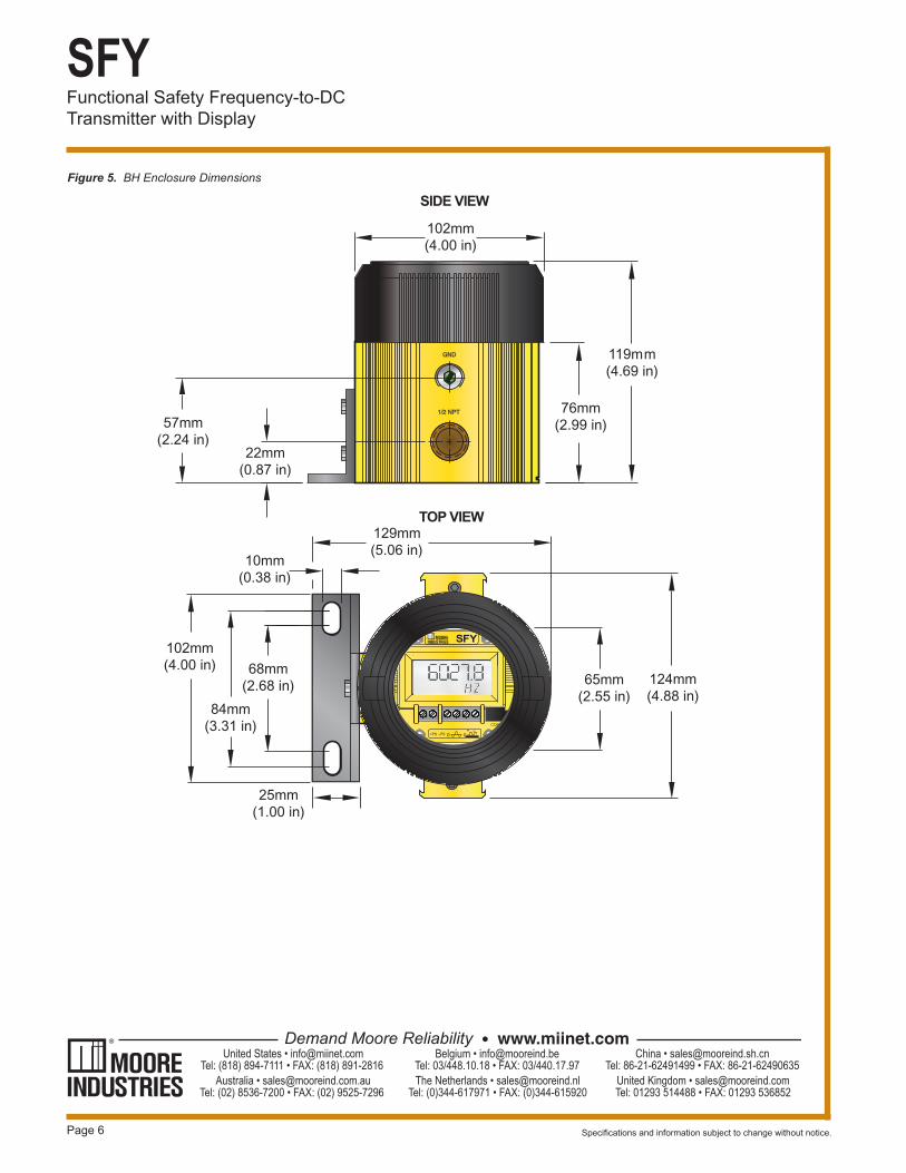
Figure 5. BH Enclosure Dimensions
+PS
65mm(2.55 in)
GND
1/2 NPT
102mm(4.00 in)
84mm(3.31 in)
68mm(2.68 in)
129mm(5.06 in)
10mm(0.38 in)
124mm(4.88 in)
25mm(1.00 in)
102mm(4.00 in)
119mm(4.69 in)
76mm(2.99 in)57mm
(2.24 in)22mm
(0.87 in)
TOP VIEW
SIDE VIEW
Specifi cations and information subject to change without notice.