Embed Size (px)
Citation preview

Freezing Point Depressant Ice Protection System DesignPresented by
Jerry JordanVice President, Design Engineering

Overview
• Freezing Point Depressant (FPD) System Description
• Design Overview
• Aircraft Physical Description
• Icing Envelope Analysis
• Panel Design Process
• Typical System Operation
• System Flow Balance
• Design Process Summary
Overview
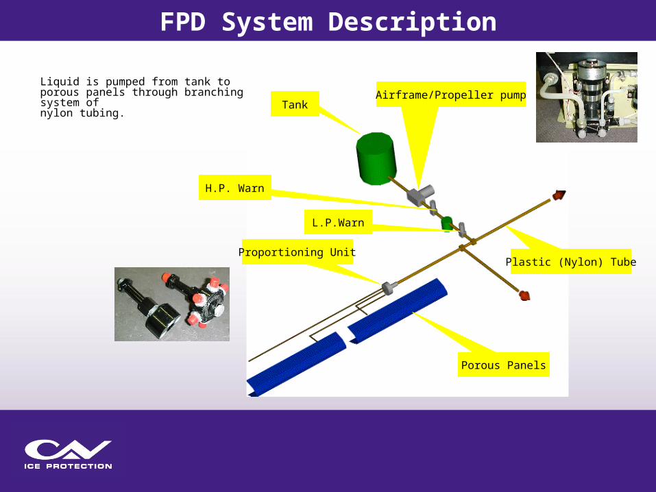
Airframe/Propeller pumpTank
H.P. Warn
L.P.Warn
Proportioning UnitPlastic (Nylon) Tube
Porous Panels
Liquid is pumped from tank to porous panels through branching system of nylon tubing.
FPD System Description

Schematic of a generic InadvertentTKS® Ice Protection System
FPD System Description
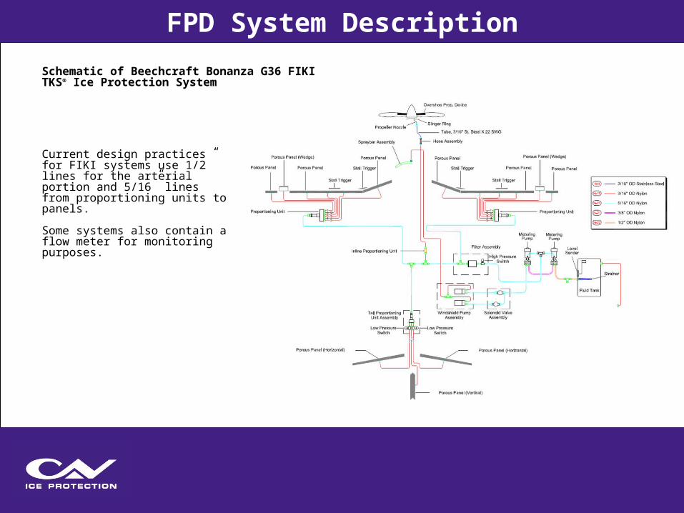
Current design practices for FIKI systems use 1/2” lines for the arterial portion and 5/16” lines from proportioning units to panels.
Some systems also contain a flow meter for monitoring purposes.
FPD System DescriptionSchematic of Beechcraft Bonanza G36 FIKITKS® Ice Protection System

Porous panels are inserted as a cuff over the leading edge of protected zones.
Liquid pumped into cavity exudes through surface to provide a protective film.
Porous Zone Fluid Supply
FPD System Description

Hardware components with electrical aspects have been qualified to DO-160F standards.
FPD system can operate in anti-ice and de-ice modes.
If liquid exuded > liquid required to maintain water catch as a liquid, system will prevent any ice formation (anti-icing).
If liquid exuded < liquid required to maintain water catch as a liquid, ice will form and shed in a natural de-ice cycle.
FPD System Description

3 Major Parts of the System Design Process
1. Flow Rate Determination
• Panel Design
• Flow Rate Determination
• Flow Rate Determination
Design Overview
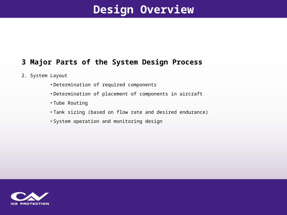
3 Major Parts of the System Design Process
2. System Layout
• Determination of required components
• Determination of placement of components in aircraft
• Tube Routing
• Tank sizing (based on flow rate and desired endurance)
• System operation and monitoring design
Design Overview
3 Major Parts of the System Design Process
3. Flow Balance
• Determines proportioning unit sizing to properly balance flow based on system layout and panel design requirements
• Provides analytical evaluation of the performance of the system throughout the icing envelope
Design Overview
Descriptions needed prior to panel design
• Define surfaces to be protected
• Define number of panels on each surface
• Determine number of inlets per panel
Descriptions needed prior to proportioning unit sizing
• Locations of equipment (pump(s), filter(s), pressure switches, proportioning units(s), etc.
• Definition of tube routings, lengths and sizes
Design Overview
Determines the design points for the TKS® Ice Protection System
Design points depend upon
• Performance properties of the aircraft
• Characteristics of the Continuous Maximum icing envelope
Design points are used to define the parameters for the impingement analysis.
Design Overview
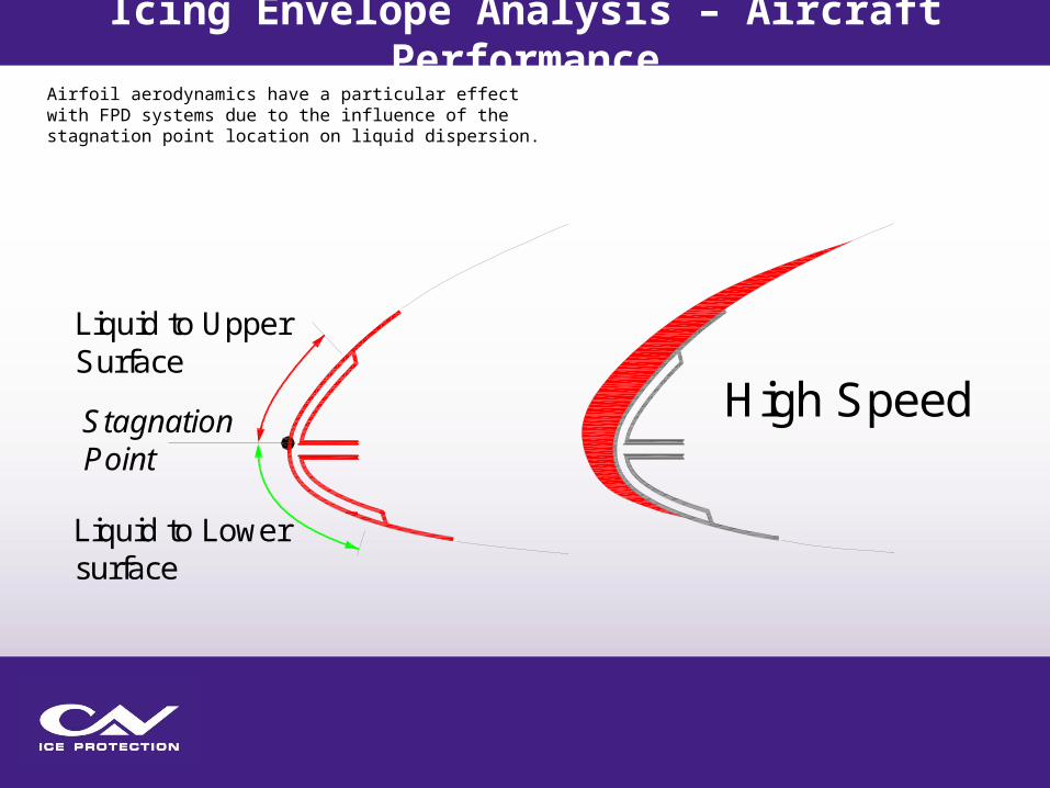
Airfoil aerodynamics have a particular effect with FPD systems due to the influence of the stagnation point location on liquid dispersion.
Stagnation Point
Liquid to Upper Surface
Liquid to Lower surface
High Speed
Icing Envelope Analysis – Aircraft Performance

At lower speeds, ice formation shifts downwards, but less fluid is available for the lower surface.
However, since water catch rate is lower due to reduced velocity, this may or may not force design for lower active area extents.
Stagnation Point
Fluid to Upper Surface
Fluid to Lower surface
Low Speed
Icing Envelope Analysis – Aircraft Performance

Performance of installed system on the aircraft will directly depend upon quality of data provided that defines the performance envelope presented.
Typical High Performance Propeller Aircraft
VyVno
Constant True Airspeed Line
Points typically used to define speedand AOA for panel design
Icing Envelope Analysis – Aircraft Performance
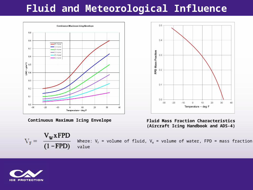
Continuous Maximum Icing Envelope Fluid Mass Fraction Characteristics(Aircraft Icing Handbook and ADS-4)
Where: VF = volume of fluid, VW = volume of water, FPD = mass fraction value
Fluid and Meteorological Influence
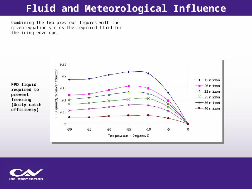
Combining the two previous figures with the given equation yields the required fluid for the icing envelope.
0
0.05
0.1
0.15
0.2
0.25
-30 -25 -20 -15 -10 -5 0
Temperature - Degrees C
FPD
qua
ntity
to p
reve
nt fr
eezi
ng
15 micron
20 micron
22 micron
25 micron
30 micron
40 micron
FPD liquid required to prevent freezing (Unity catch efficiency)
Fluid and Meteorological Influence
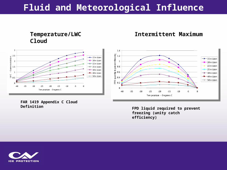
FAR 1419 Appendix C Cloud Definition
0
0.5
1
1.5
2
2.5
3
-40 -35 -30 -25 -20 -15 -10 -5 0
Temperature - Degrees C
LWC
- G
ram
mes
/cub
ic m
.
15 micron
20 micron
22 micron
25 micron
30 micron
40 micron
50 micron
0
0.2
0.4
0.6
0.8
1
1.2
1.4
-40 -35 -30 -25 -20 -15 -10 -5 0
Temperature - Degrees C
FPD
qua
ntity
to p
reve
nt fr
eezi
ng
15 micron
20 micron
22 micron
25 micron
30 micron
40 micron
50 micron
Temperature/LWC Intermittent Maximum Cloud
FPD liquid required to prevent freezing (unity catch efficiency)
Fluid and Meteorological Influence
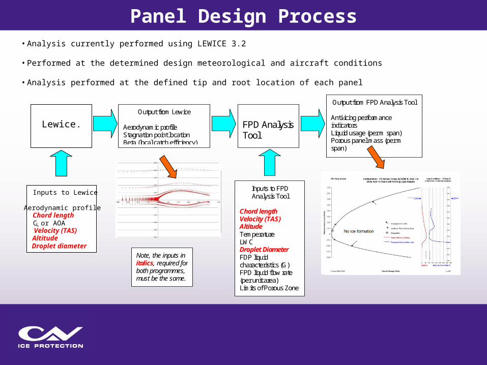
Output from Lewice
Aerodynamic profileStagnation point locationBeta (local catch efficiency)
FPD AnalysisTool
Inputs to FPDAnalysis Tool
Chord lengthVelocity (TAS)AltitudeTemperatureLWCDroplet DiameterFDP liquidcharacteristics (G)FPD liquid flow rate(per unit area)Limits of Porous Zone
Output from FPD Analysis Tool
Anti-icing performanceindicatorsLiquid usage (per m span)Porous panel mass (per mspan)
Note, the inputs initalics, required forboth programmes,must be the same.
-3
-2
-1
0
1
2
3
-2 -1 0 1 2 3 4 5 6 7 8
-0.04
-0.03
-0.02
-0.01
0
0.01
0.02
0.03
0.04
0.05
0.06
0.07
0.08
Dim
esns
ionl
ess
y-co
ordi
nate
Lower lImit of porous zone (xL)
Stagnation Point Location
0.0 2.0 4.0 6.0
1
2
3
4
5
6
7
8
9
10
11
12
13
14
15
16
17
18
19
20
21
22
23
24
25
26
27
28
29
30
31
32
33
34
35
36
37
38
-0.04
-0.02
0
0.02
0.04
0.06
0.08
0 50 100 150
Potential ice build rate - mm/minGrey bars - water collectedBlack bars - ice formation
#946 Run 51 @ 5 mins
% of fluid required to anti-ice
Flight Conditions: Cruise, Alt 13000, Speed 100.33m/s, (159 kcas)
Cloud: -20 deg C, 20 micron, 0.2 gm/m 3̂
Flow rate per metre span 25.3 ml/min
Panel mass per metre span 0.56 kg
Panel data: xU/c 0.0088, xL/c 0.009, sp flow 0.069 ml/min/cm^2
Beta(%)
Impingement Limit
Impingement Limit
Upper lImit of porous zone (xU)
Stagnation Point Location
Lewice.
Inputs to Lewice
Aerodynamic profileChord lengthCL or AOAVelocity (TAS)AltitudeDroplet diameter
• Analysis currently performed using LEWICE 3.2
• Performed at the determined design meteorological and aircraft conditions
• Analysis performed at the defined tip and root location of each panel
Panel Design Process

Results from LEWICE impingement analysis are used to determine water catch and fluid requirement in FPD analysis tool.
Front Edge of Panel FT OUT
FEX
WINWINU + FRU
WIN Liquid Water Catch entering zoneFEX FPD liquid exuded from surface into zoneFR FDP liquid required to maintain WIN liquidFTIN Excess fluid transferred downstreamWINU Liquid Water Catch from upstream zonesFRU FPD liquid required to maintain WINU liquid.
First Control Volume
Panel Design Process

FEX
WIN
WINU + FRU
FT IN
WINU + FRU
WIN Liquid Water Catch entering zoneFEX FPD liquid exuded from surface into zoneFR FDP liquid required to maintain WIN liquidFTIN Excess fluid transferred downstreamWINU Liquid Water Catch from upstream zonesFRU FPD liquid required to maintain WINU liquid.
Control Volume at Max Impingement
Panel Design ProcessResults from LEWICE impingement analysis are used to determine water catch and fluid requirement in FPD analysis tool.
FEX
FT OUT
WIN
WINU + FRU
WINU + FRU + WIN + FR
WIN Liquid Water Catch entering zoneFEX FPD liquid exuded from surface into zoneFR FDP liquid required to maintain WIN liquidFTIN Excess fluid transferred downstreamWINU Liquid Water Catch from upstream zonesFRU FPD liquid required to maintain WINU liquid.
First Control Volume Aft of Max Impingement
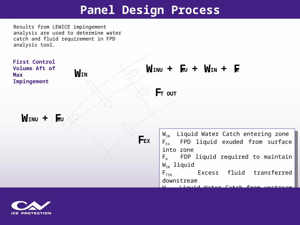
Panel Design ProcessResults from LEWICE impingement analysis are used to determine water catch and fluid requirement in FPD analysis tool.

WIN Liquid Water Catch entering zoneFEX FPD liquid exuded from surface into zoneFR FDP liquid required to maintain WIN liquidFTIN Excess fluid transferred downstreamWINU Liquid Water Catch from upstream zonesFRU FPD liquid required to maintain WINU liquid.
FT OUT
WIN
WINU + FRU
FT IN
WINU + FRU + WIN + FRControl Volume Aft of Active Area
Panel Design ProcessResults from LEWICE impingement analysis are used to determine water catch and fluid requirement in FPD analysis tool.

No ice formation
Flow and active zone optimized at design point
Panel Design Process
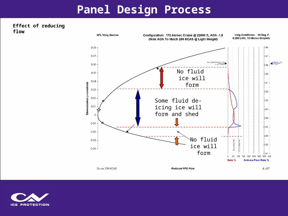
No ice formation
Effect of reducing flow
Some fluid de-icing ice will form and shed
No fluid ice will form
No fluid ice will form
Panel Design Process

No ice formation
Effect of lowering upper limit of active zone
Some fluid de-icing ice will form and shed
No fluid ice will form
No fluid ice will form
No fluid ice will form
No ice formation
Panel Design Process

No ice formation
Effect of raising lower limit of active zone
Some fluid de-icing ice will form and shed
No fluid ice will form
No fluid ice will form
No fluid ice will form
No ice formation
No ice formation
Insufficient fluid ice will form
Panel Design Process
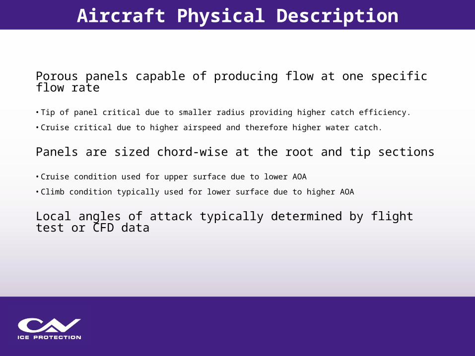
Porous panels capable of producing flow at one specific flow rate
• Tip of panel critical due to smaller radius providing higher catch efficiency.
• Cruise critical due to higher airspeed and therefore higher water catch.
Panels are sized chord-wise at the root and tip sections
• Cruise condition used for upper surface due to lower AOA
• Climb condition typically used for lower surface due to higher AOA
Local angles of attack typically determined by flight test or CFD data
Aircraft Physical Description

• Icing Wind Tunnel test typically used to verify panel design
• Same panel design tool used for icing wind tunnel predictive analysis which verifies tool
Analysis for Design Condition
Panel Design Process

Protected Area
Unprotected Area
Panel Design Process

Analysis can also predict performance in environments beyond the design condition where system functions in de-ice mode.
No fluid ice will form
Some fluid de-icingice will form and shed
No fluid ice will form
Anti-icing (no ice)
Panel Design Process

System will clear ice after encounter is over.
Panel Design Process
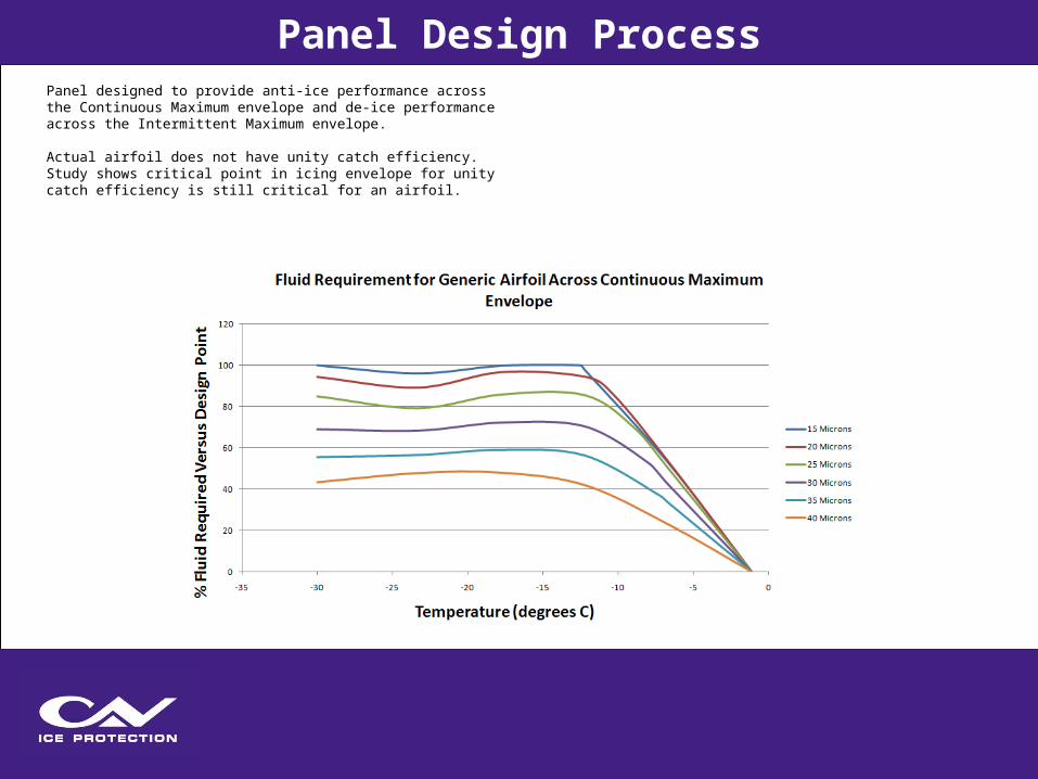
Panel designed to provide anti-ice performance across the Continuous Maximum envelope and de-ice performance across the Intermittent Maximum envelope.
Actual airfoil does not have unity catch efficiency. Study shows critical point in icing envelope for unity catch efficiency is still critical for an airfoil.
Panel Design Process

Typical Inadvertent System Operation
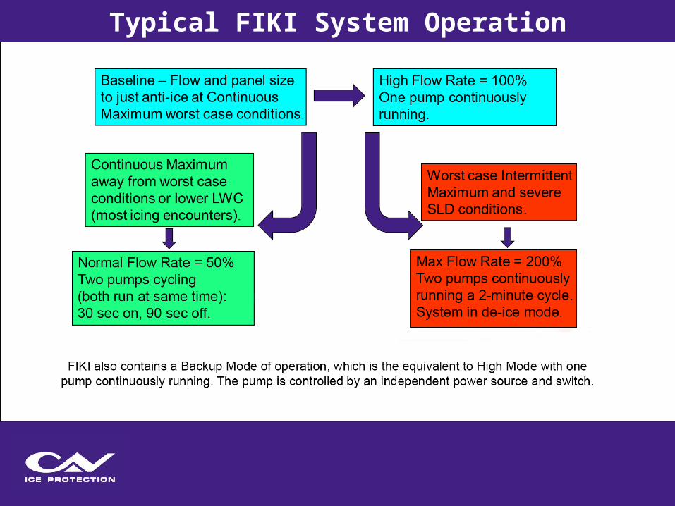
Typical FIKI System Operation

System is balanced by introduction of proportioning unit(s) which provide a defined pressure drop to direct flow appropriately.
Proportioning unit sizing is dependent upon flow rate, line lengths and line sizes.
Upon sizing of proportioning unit, analysis can be performed to estimate system performance (pressures and flow rates) across the entire icing envelope.
System Flow Balance
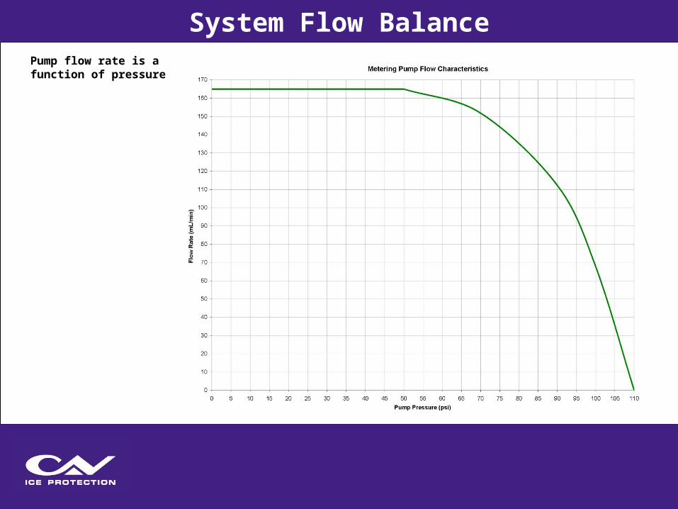
Pump flow rate is a function of pressure
System Flow Balance

Pump pressure changes with temperature
• Caused by change in viscosity
• Influenced by line sizes
• Influenced by number of filters
System Flow Balance
Aircraft physical description and aerodynamic data is defined.
Using obtained information, panels are designed, components are chosen and the system is laid out.
Using the system layout and panel design, a flow balance is performed to define proportioning unit requirements.
During the process, various tests and analysis are performed to ensure the system meets regulations for certification.
Design Process Summary
Icing Consultinghttps://www.caviceprotection.com/oem-design-consulting/other
Freezing Point Depressant System Designhttps://www.caviceprotection.com/oem-design-consulting/freezing-point
Freezing Point Depressant System Design Certification Supporthttps://www.caviceprotection.com/oem-design-consulting/freezing-point-certification
Related Links

Email [email protected]
Phone US +1 (913) 738 5404
UK +44 (0) 1207 599140
www.caviceprotection.com
Contact