Embed Size (px)
Citation preview
T
A B
The Concurrent System
The Free Body Diagram
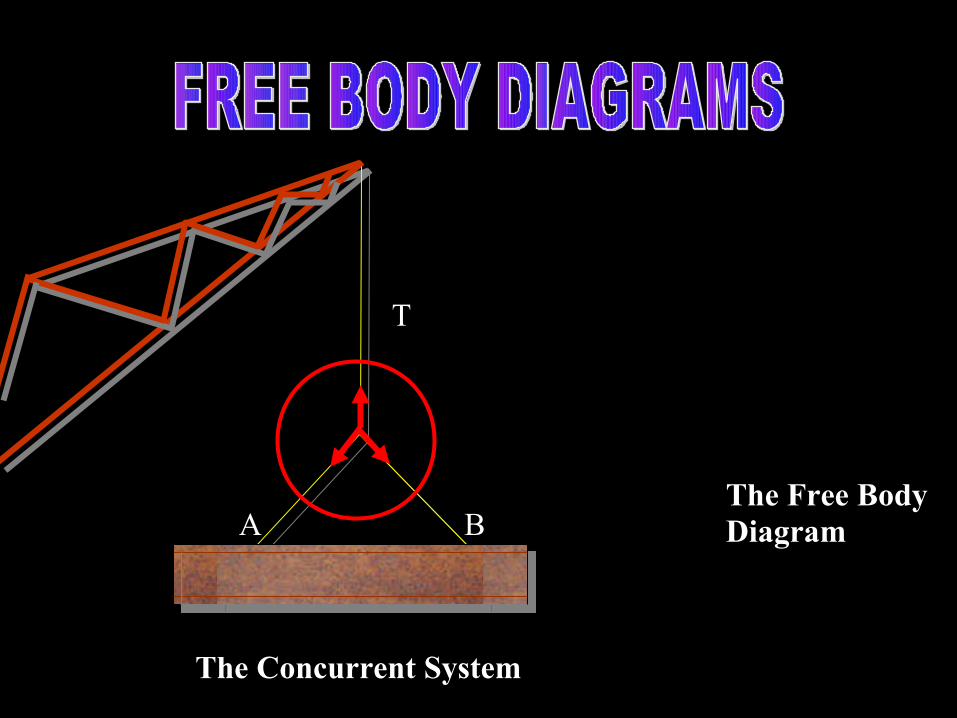
Concept of Free Body Diagrams
Particle System
Rigid Body
Systems
Concept of Equilibrant
Graphical Determination of
Equilibrant
Applied and Reaction Forces in
Beams
Types of Beam
Supports
Free Body diagram of Rigid Bodies
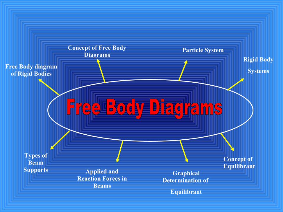
Free Body Diagrams
• Essential step in solving Equilibrium problems
•Complex Structural systems reduced into concise FORCE systems
WHAT IS A FREE BODY DIAGRAM?
A FBD is a simplified representation of a PARTICLE or RIGID BODY that is isolated from its surroundings and on which all applied forces and reactions are shown.
All forces acting on a particle original body must be considered, and equally important any force not directly applied on the body must be excluded.
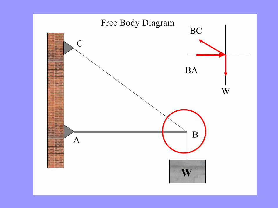
W
AB
C
W
BC
BA
Free Body Diagram
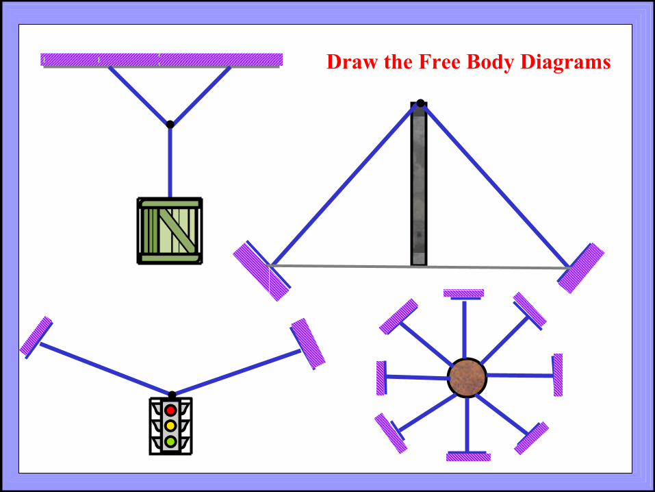
Draw the Free Body Diagrams

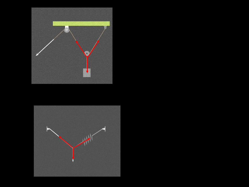
REAL LIFE CONCURRENT SYSTEMS
Equilibrium of a Particle

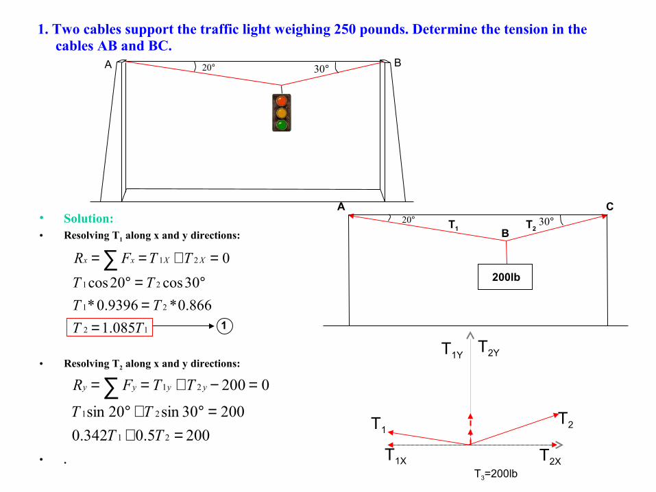
1. Two cables support the traffic light weighing 250 pounds. Determine the tension in the cables AB and BC.
• Solution:• Resolving T1 along x and y directions:
• Resolving T2 along x and y directions:
• .
°20 °30A B
°20 °30
200lb
A C
BT1 T2
T1T2
T1YT2Y
T1X T2XT3=200lb
12
21
21
21
085.1
866.0*9396.0*
30cos20cos
0
TT
TT
TT
TTFR XXxx
==
°=°
=+== ∑
2005.0342.0
20030sin20sin
0200
21
21
21
=+=°+°
=−+== ∑
TT
TT
TTFR yyyy
1
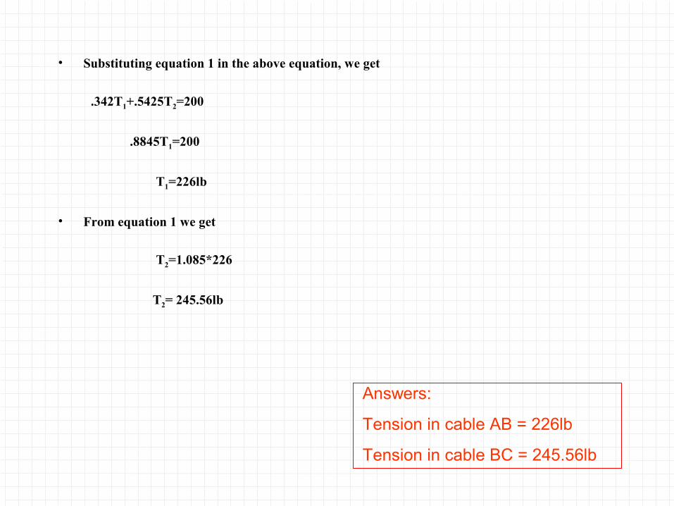
• Substituting equation 1 in the above equation, we get
.342T1+.5425T2=200
.8845T1=200
T1=226lb
• From equation 1 we get
T2=1.085*226
T2= 245.56lb
Answers:
Tension in cable AB = 226lb
Tension in cable BC = 245.56lb
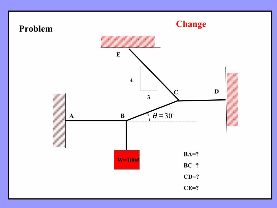
W=100#
A
C D
E
B 30=θ
4
3
BA=?
BC=?
CD=?
CE=?
Problem Change
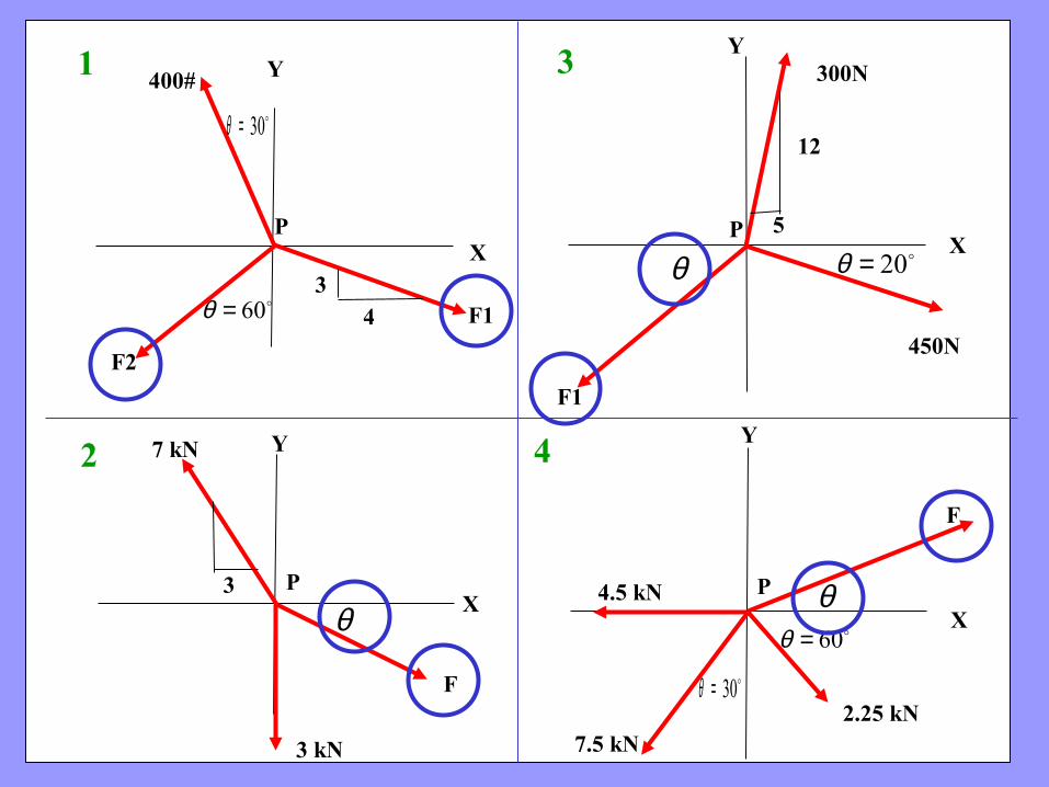
400#
F1
F2
300N
450N
F1
X
Y
X
XX
Y
Y Y
30=θ
60=θ
F
3 kN
7 kN
4.5 kN
7.5 kN2.25 kN
F
60=θ30=θ
P P
PP
1
2
3
4
θθ
θ 20=θ
4
3
12
5
3
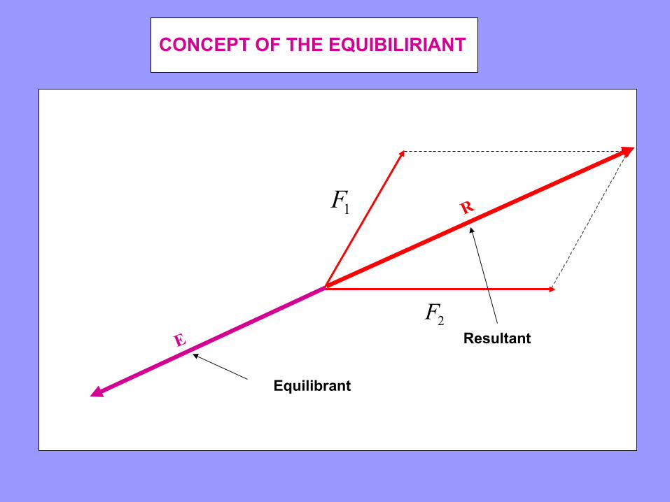
CONCEPT OF THE EQUIBILIRIANT
Resultant
1F
2F
R
E
Equilibrant
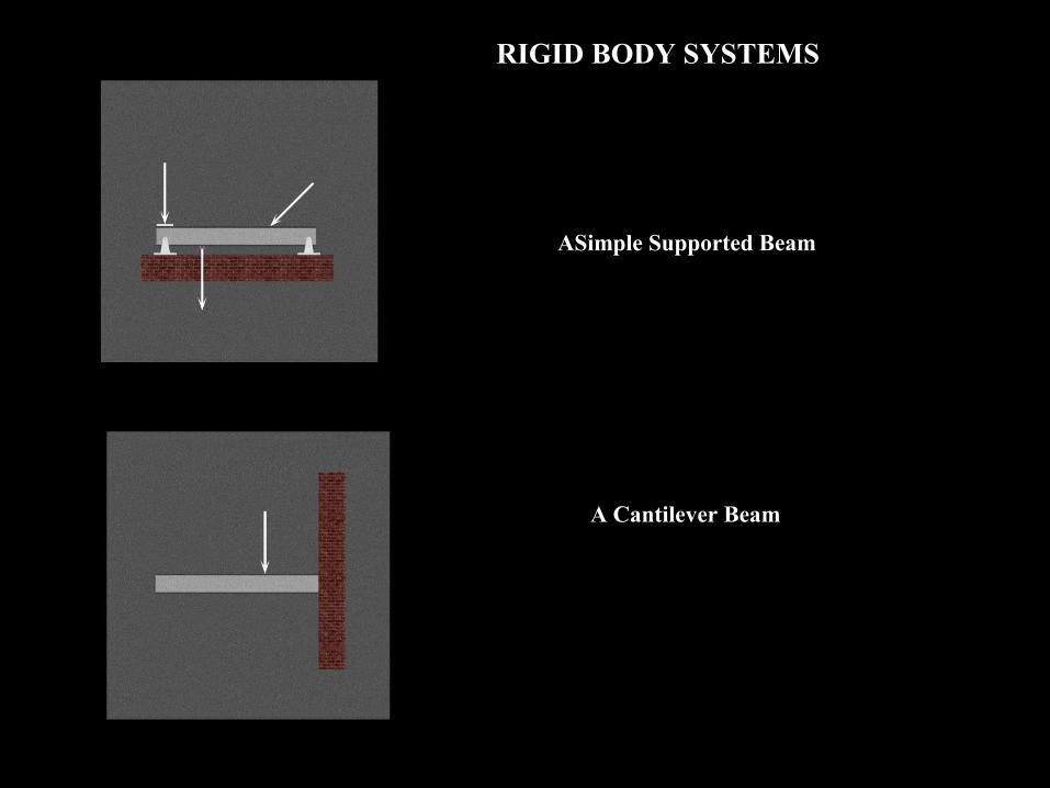
ASimple Supported Beam
A Cantilever Beam
RIGID BODY SYSTEMS
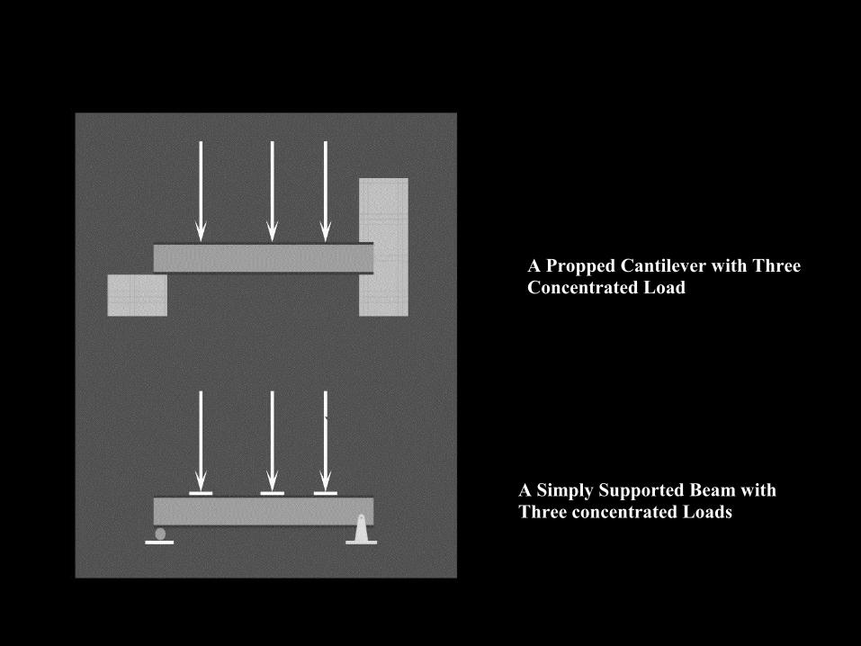
A Propped Cantilever with Three Concentrated Load
A Simply Supported Beam with Three concentrated Loads
APPLIED AND REACTION FORCES IN BEAMS
In the Chapter on Force Systems, we discussed the concept of APPLIED FORCES, REACTION FORCES and INTERNAL FORCES
Here we well discuss the relevance and importance of APPLIED FORCES and REACTION FORCES in the case of Beams.
Before we proceed further please study the animated visuals on the next slide
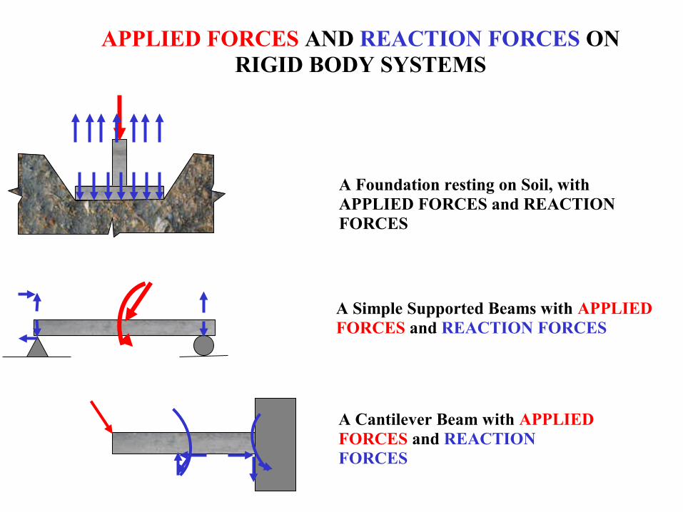
APPLIED FORCES AND REACTION FORCES ON RIGID BODY SYSTEMS
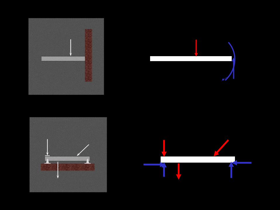
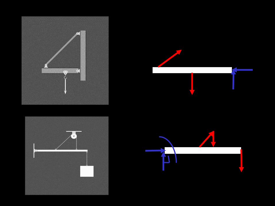
A Foundation resting on Soil, with APPLIED FORCES and REACTION FORCES
A Simple Supported Beams with APPLIED FORCES and REACTION FORCES
A Cantilever Beam with APPLIED FORCES and REACTION FORCES
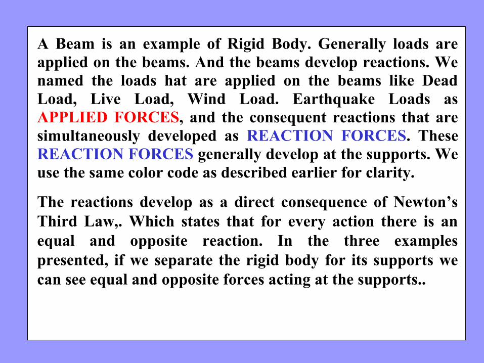
A Beam is an example of Rigid Body. Generally loads are applied on the beams. And the beams develop reactions. We named the loads hat are applied on the beams like Dead Load, Live Load, Wind Load. Earthquake Loads as APPLIED FORCES, and the consequent reactions that are simultaneously developed as REACTION FORCES. These REACTION FORCES generally develop at the supports. We use the same color code as described earlier for clarity.
The reactions develop as a direct consequence of Newton’s Third Law,. Which states that for every action there is an equal and opposite reaction. In the three examples presented, if we separate the rigid body for its supports we can see equal and opposite forces acting at the supports..
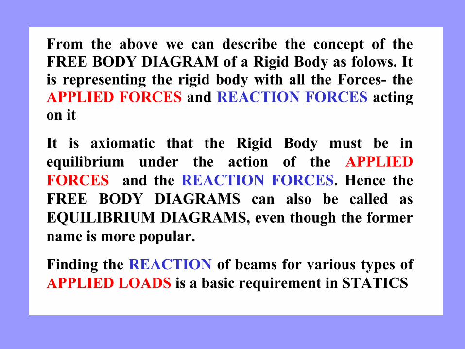
From the above we can describe the concept of the FREE BODY DIAGRAM of a Rigid Body as folows. It is representing the rigid body with all the Forces- the APPLIED FORCES and REACTION FORCES acting on it
It is axiomatic that the Rigid Body must be in equilibrium under the action of the APPLIED FORCES and the REACTION FORCES. Hence the FREE BODY DIAGRAMS can also be called as EQUILIBRIUM DIAGRAMS, even though the former name is more popular.
Finding the REACTION of beams for various types of APPLIED LOADS is a basic requirement in STATICS
The above diagrams, which show the complete system of applied and reactive forces acting on a body, are called free body diagrams.
The whole system of applied and reactive forces acting on a body must be in a state of equilibrium. Free-body diagrams are, consequently ,often called equilibrium diagrams.
Drawing equilibrium diagrams and finding reactions for loaded structural members is a common first step in a complete structural analysis
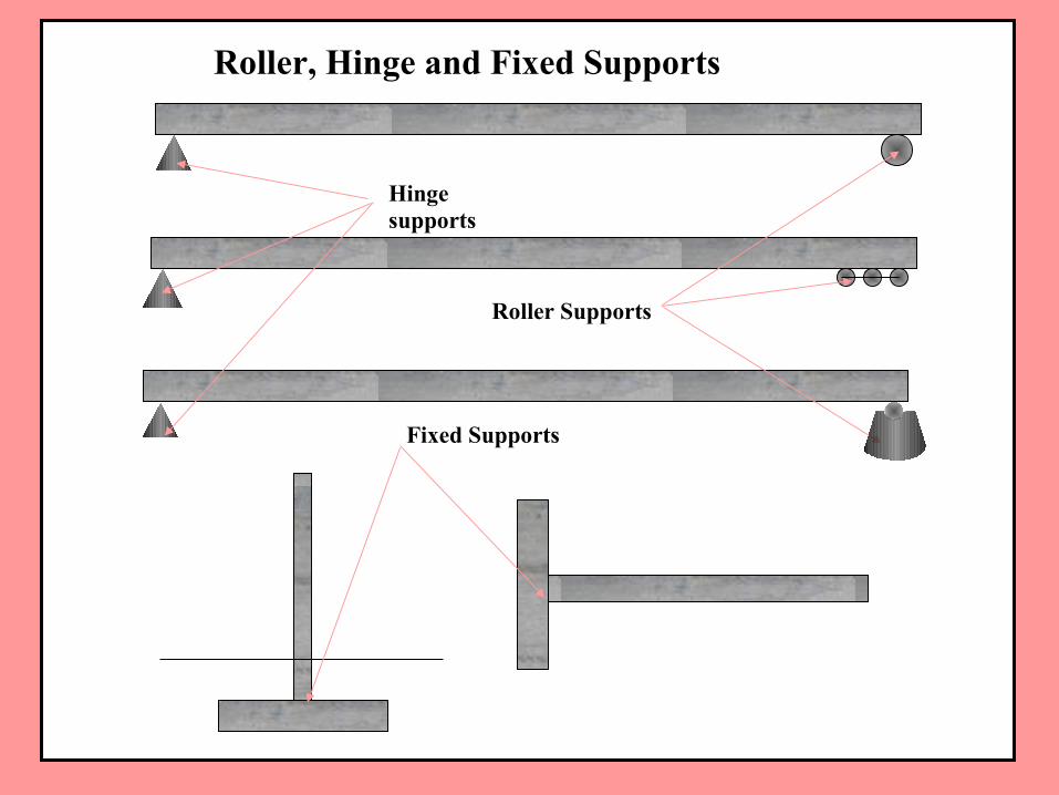
Roller, Hinge and Fixed Supports
Hinge supports
Roller Supports
Fixed Supports
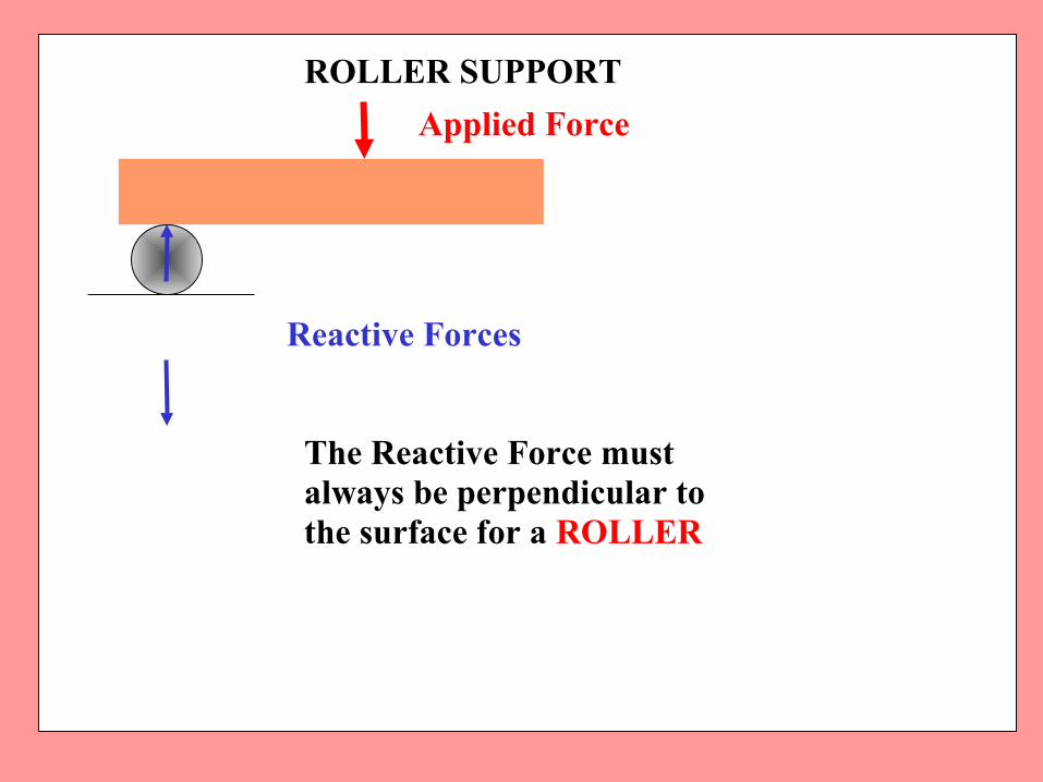
ROLLER SUPPORT
Applied Force
Reactive Forces
The Reactive Force must always be perpendicular to the surface for a ROLLER
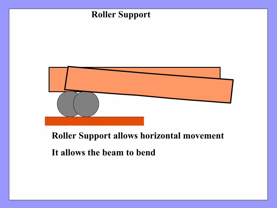
Roller Support
Roller Support allows horizontal movement
It allows the beam to bend
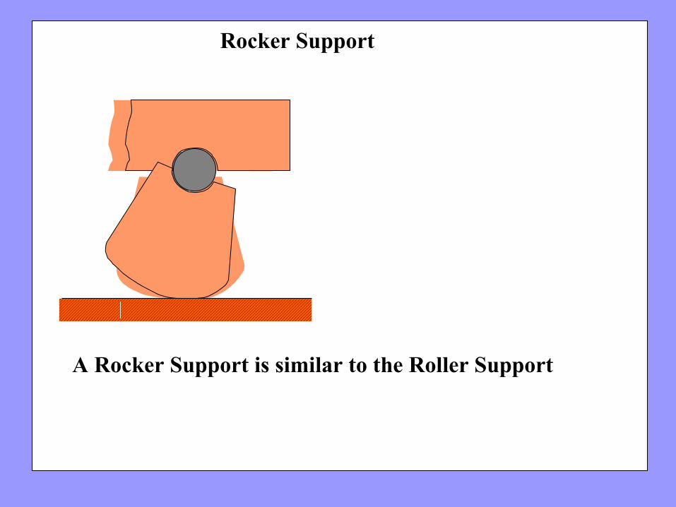
Rocker Support
A Rocker Support is similar to the Roller Support
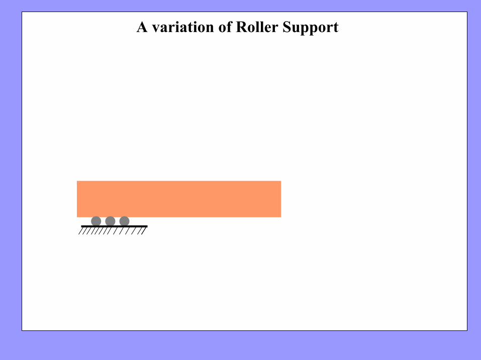
A variation of Roller Support
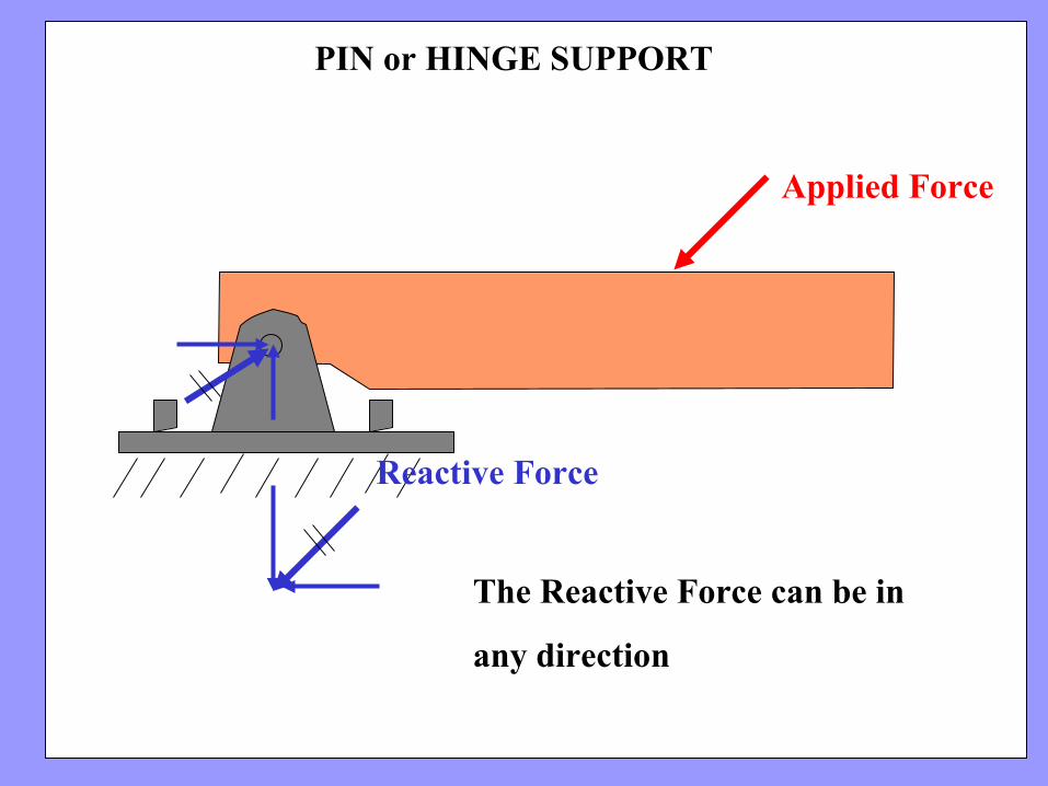
PIN or HINGE SUPPORT
Applied Force
Reactive Force
The Reactive Force can be in
any direction

Pin or Hinge Support
Pin support does no allow any movement
It allows the beam to bend
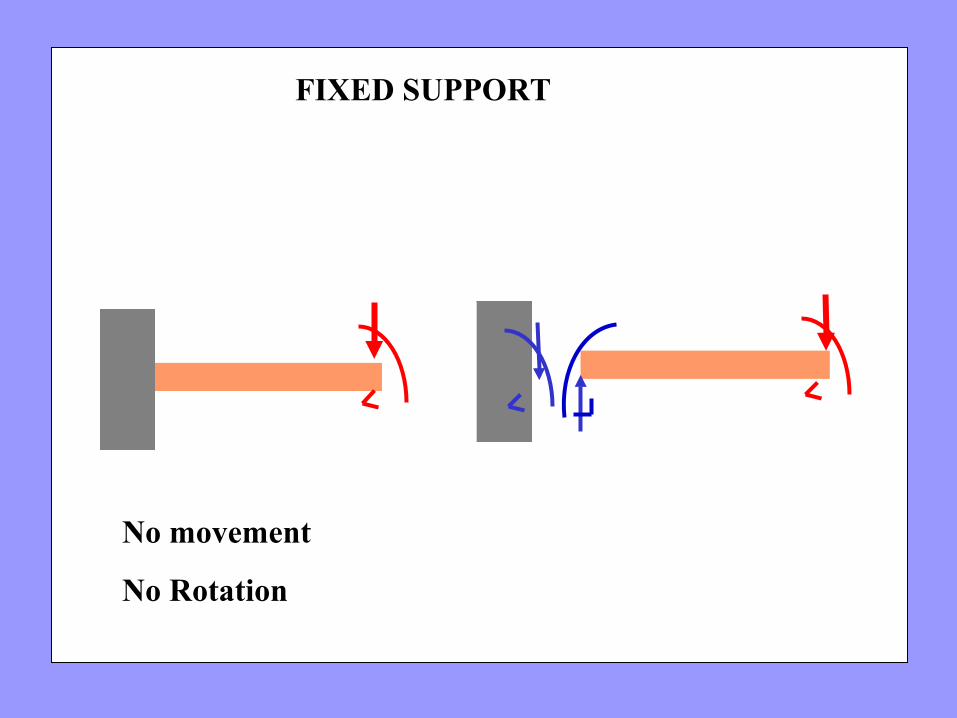
FIXED SUPPORT
No movement
No Rotation
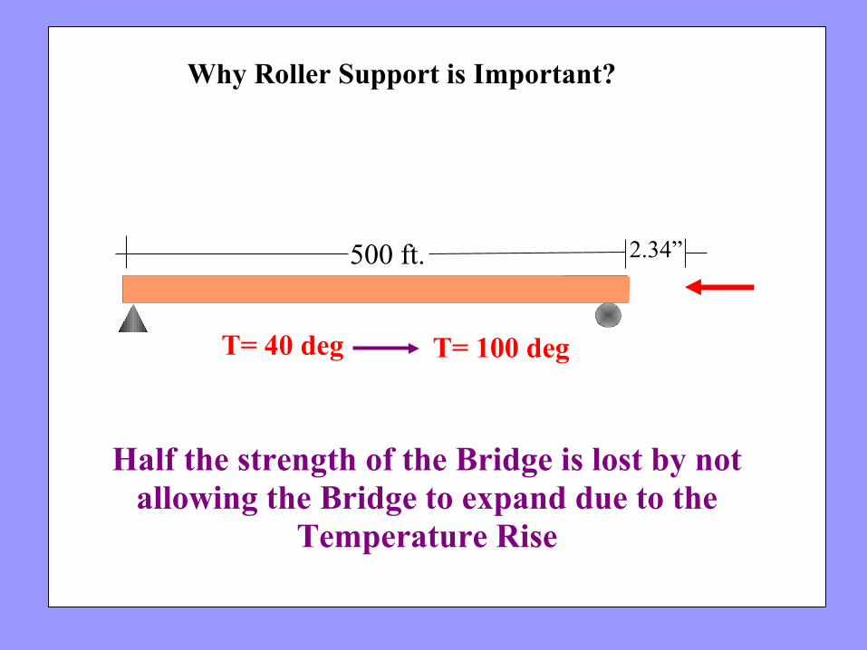
Half the strength of the Bridge is lost by not allowing the Bridge to expand due to the
Temperature Rise
Why Roller Support is Important?
500 ft. 2.34”
T= 100 degT= 40 deg
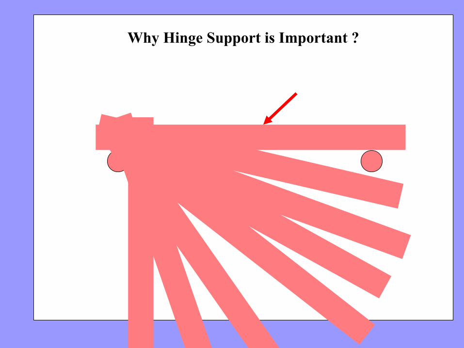
Why Hinge Support is Important ?
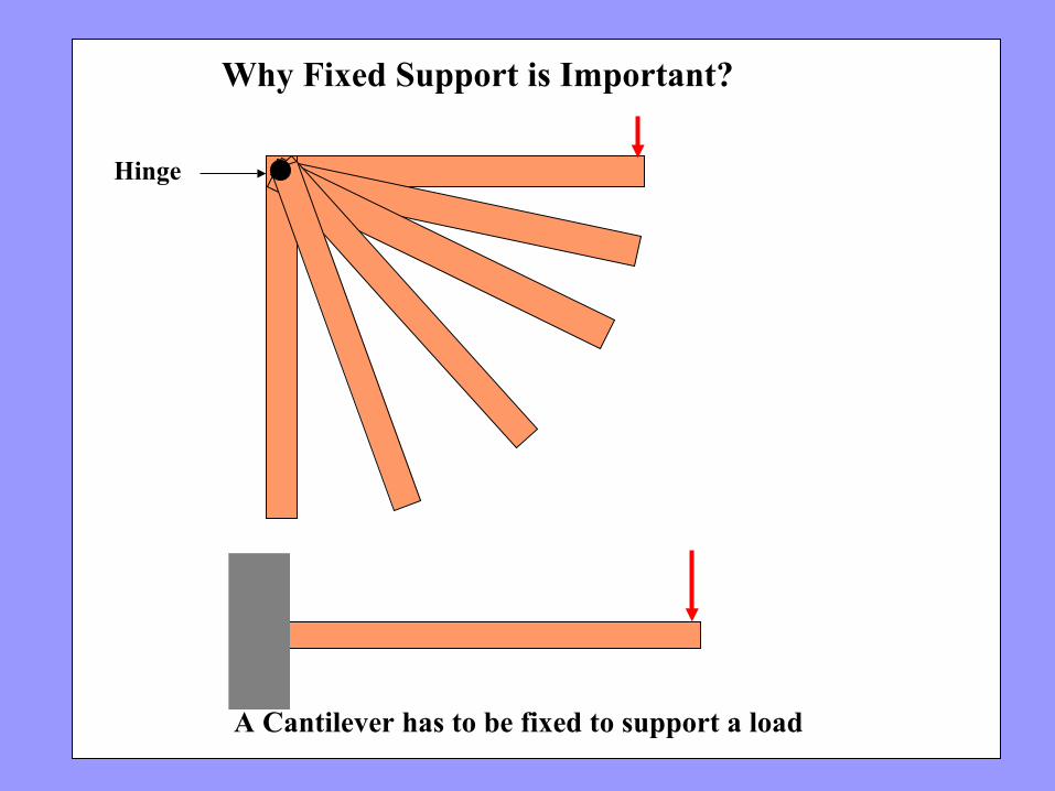
Why Fixed Support is Important?
A Cantilever has to be fixed to support a load
Hinge
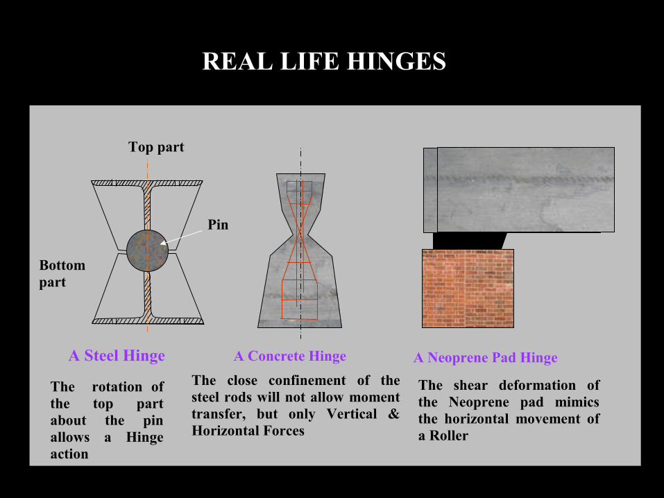
REAL LIFE HINGES
A Steel Hinge A Concrete Hinge A Neoprene Pad Hinge
The shear deformation of the Neoprene pad mimics the horizontal movement of a Roller
The close confinement of the steel rods will not allow moment transfer, but only Vertical & Horizontal Forces
Top part
Bottom part
Pin
The rotation of the top part about the pin allows a Hinge action
Question 1. What is the difference between a Rigid Body and a Particle
Question 2: Explain the Difference between a Roller Support, Hinge Support and Fixed Support
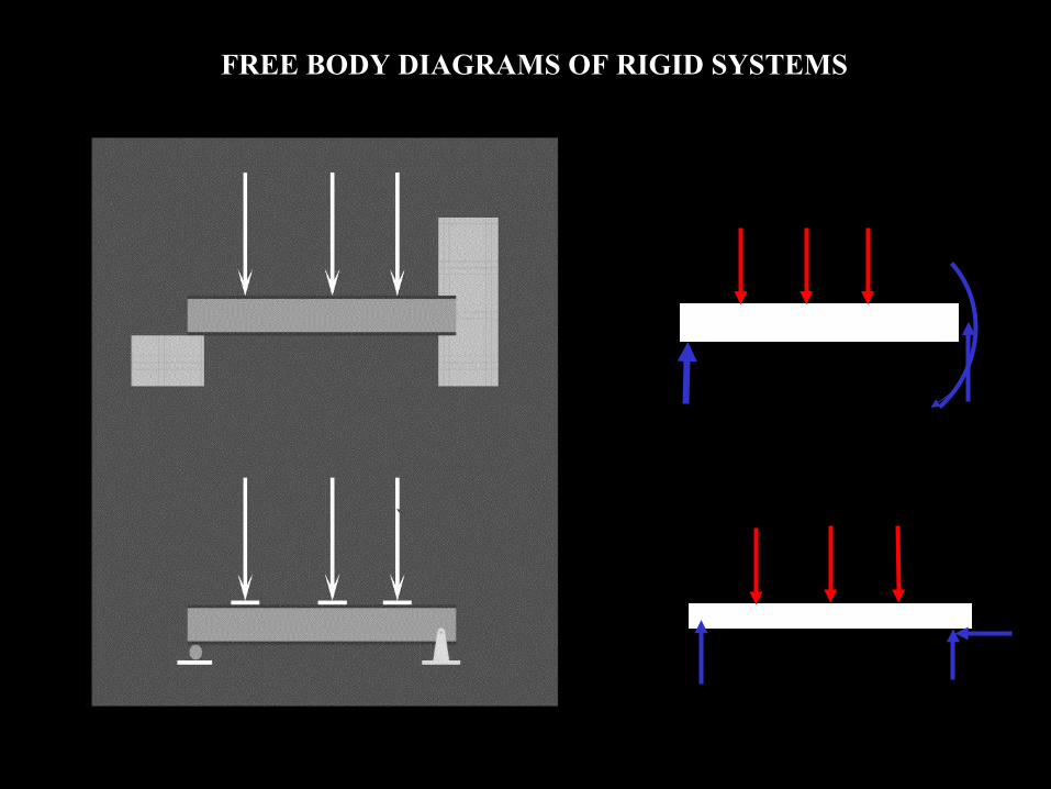
FREE BODY DIAGRAMS OF RIGID SYSTEMS
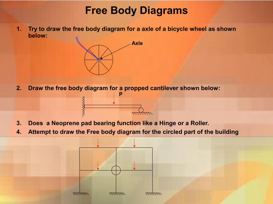
Free Body Diagrams
1. Try to draw the free body diagram for a axle of a bicycle wheel as shown below:
2. Draw the free body diagram for a propped cantilever shown below:
3. Does a Neoprene pad bearing function like a Hinge or a Roller.
4. Attempt to draw the Free body diagram for the circled part of the building
P
Axle
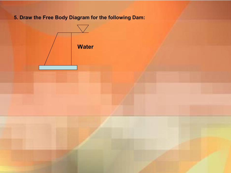
5. Draw the Free Body Diagram for the following Dam:
Water