Embed Size (px)
Citation preview
Flite Software N.I. Ltd, Block E, Balliniska Business Park, Springtown Rd,
Derry, BT48 0LY, N. Ireland. T: 44 (0) 2871 279227 | E: [email protected] | www.fluidflowinfo.com
FluidFlow
PRODUCT OVERVIEW ©Flite Software 2016

FluidFlow Product Overview Page 1
1 Introduction ................................................................................................................................................... 2
2 Liquid Module (Incompressible Flow). ........................................................................................................... 4
3 Gas Module (Compressible Flow). ................................................................................................................. 7
4 Two-Phase Liquid-Gas Module. ..................................................................................................................... 9
5 Slurry Module .............................................................................................................................................. 10
6 Scripting Module - Dynamic Analysis. .......................................................................................................... 11
7 Heat Transfer ............................................................................................................................................... 13
8 FluidFlow FAQ’s............................................................................................................................................ 14
FluidFlow Product Overview Page 2
1 Introduction
FluidFlow is designed to allow the modelling of fluid behaviour within complex piping
systems and accurately predict how the system will work for a given set of boundary
conditions. The software uses a number of well-established models and correlations to
solve the piping systems.
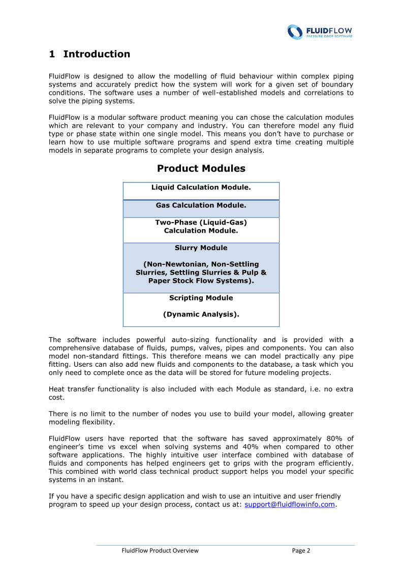
FluidFlow is a modular software product meaning you can chose the calculation modules
which are relevant to your company and industry. You can therefore model any fluid
type or phase state within one single model. This means you don’t have to purchase or
learn how to use multiple software programs and spend extra time creating multiple
models in separate programs to complete your design analysis.
Product Modules
Liquid Calculation Module.
Gas Calculation Module.
Two-Phase (Liquid-Gas)
Calculation Module.
Slurry Module
(Non-Newtonian, Non-Settling
Slurries, Settling Slurries & Pulp &
Paper Stock Flow Systems).
Scripting Module
(Dynamic Analysis).
The software includes powerful auto-sizing functionality and is provided with a
comprehensive database of fluids, pumps, valves, pipes and components. You can also
model non-standard fittings. This therefore means we can model practically any pipe
fitting. Users can also add new fluids and components to the database, a task which you
only need to complete once as the data will be stored for future modeling projects.
Heat transfer functionality is also included with each Module as standard, i.e. no extra
cost.
There is no limit to the number of nodes you use to build your model, allowing greater
modeling flexibility.
FluidFlow users have reported that the software has saved approximately 80% of
engineer’s time vs excel when solving systems and 40% when compared to other
software applications. The highly intuitive user interface combined with database of
fluids and components has helped engineers get to grips with the program efficiently.
This combined with world class technical product support helps you model your specific
systems in an instant.
If you have a specific design application and wish to use an intuitive and user friendly
program to speed up your design process, contact us at: [email protected].

FluidFlow Product Overview Page 3
This document also contains a list of FAQ’s which you are free to peruse at your
convenience.
Testimonial:
“MAN Diesel & Turbo’s activities in the power plant sector are based on a well-
established range of diesel engines and a rapidly growing gas engine offering. The
products range from small emergency power generators to turnkey power plants with
outputs of up to 400 MW. We use the liquid, gas, and two-phase modules of FluidFlow
and make extensive use of its simulation capabilities for engineering sub systems as fuel
gas lines or cooling water pressure systems, including for the development of new
systems. Before we bought we carried out extensive product research and chose
FluidFlow because of its completeness and value for money. We have had to make
occasional technical support calls and have been impressed by the responsiveness. We
have found Flite Software to be extremely knowledgeable and helpful, really excellent.”
Norman Kurth, System Engineering, MAN Diesel & Turbo, Germany.
FluidFlow Product Overview Page 4
2 Liquid Module (Incompressible Flow).
Design your liquid pipe flow systems in an instant with the FluidFlow Liquid Module. This
calculation module is used by engineers to calculate plant operating pressures, pressure
losses and flow distribution in liquid piping transportation systems.
The software includes powerful equipment sizing functionality meaning you can
accurately size pipes, orifice plates, control valves, relief valves, centrifugal and PD
pumps.
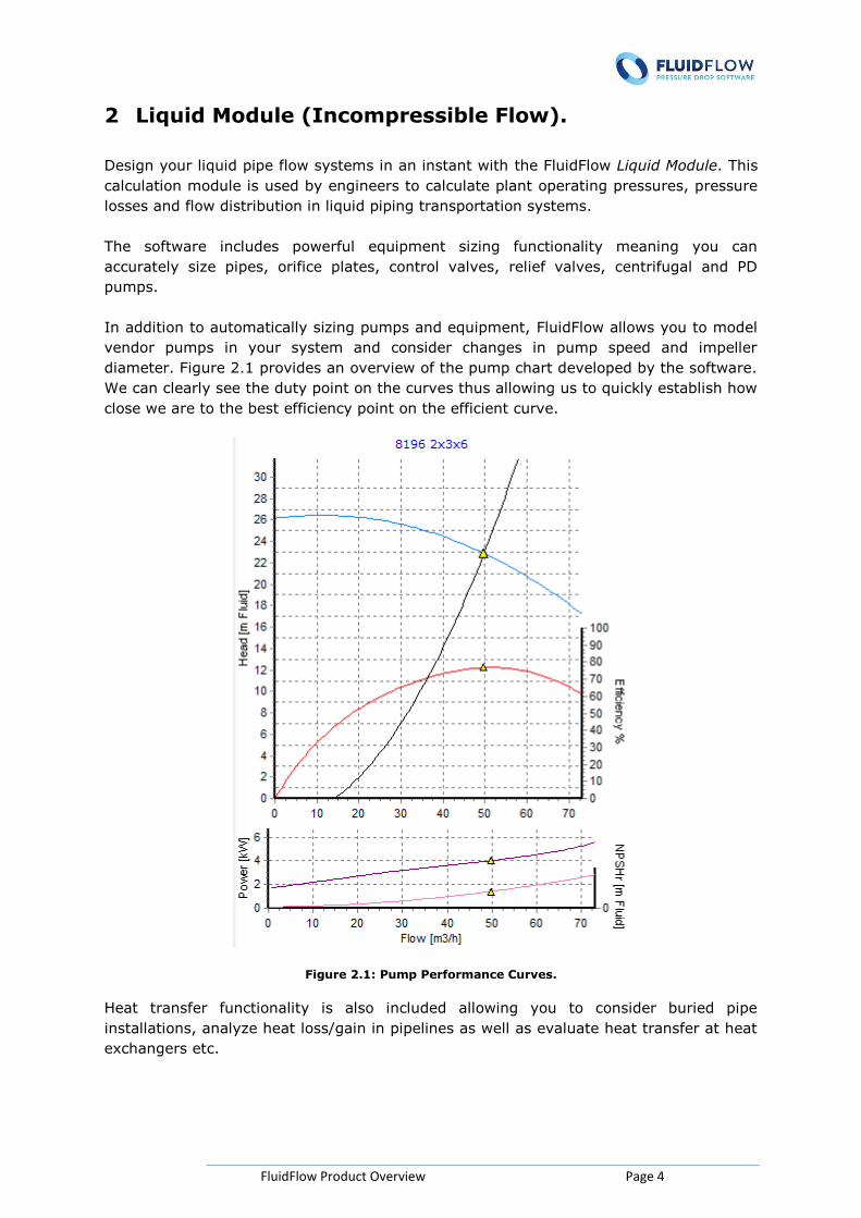
In addition to automatically sizing pumps and equipment, FluidFlow allows you to model
vendor pumps in your system and consider changes in pump speed and impeller
diameter. Figure 2.1 provides an overview of the pump chart developed by the software.
We can clearly see the duty point on the curves thus allowing us to quickly establish how
close we are to the best efficiency point on the efficient curve.
Figure 2.1: Pump Performance Curves.
Heat transfer functionality is also included allowing you to consider buried pipe
installations, analyze heat loss/gain in pipelines as well as evaluate heat transfer at heat
exchangers etc.
FluidFlow Product Overview Page 5
The software is provided with a comprehensive database of fluids, pipes, pumps and
fittings. You can also add new fluids and components to the database, a task which you
only need to complete once as the data will be stored for future modeling projects.
For liquid (incompressible flow) calculations, FluidFlow solves the fundamental
conservation equations of mass, energy, and momentum. Users can choose from three
pipe pressure loss models as follows; 1) Moody (Darcy-Weisbach), 2) Hazen Williams or
3) Fixed Friction Factor (Darcy).
Users have the ability to choose from database values for pipe roughness and pipe scale
build up. You can also directly define your own specific values for both roughness and
scaling.
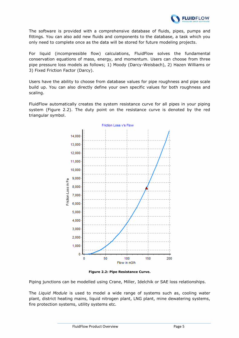
FluidFlow automatically creates the system resistance curve for all pipes in your piping
system (Figure 2.2). The duty point on the resistance curve is denoted by the red
triangular symbol.
Figure 2.2: Pipe Resistance Curve.
Piping junctions can be modelled using Crane, Miller, Idelchik or SAE loss relationships.
The Liquid Module is used to model a wide range of systems such as, cooling water
plant, district heating mains, liquid nitrogen plant, LNG plant, mine dewatering systems,
fire protection systems, utility systems etc.
FluidFlow Product Overview Page 6
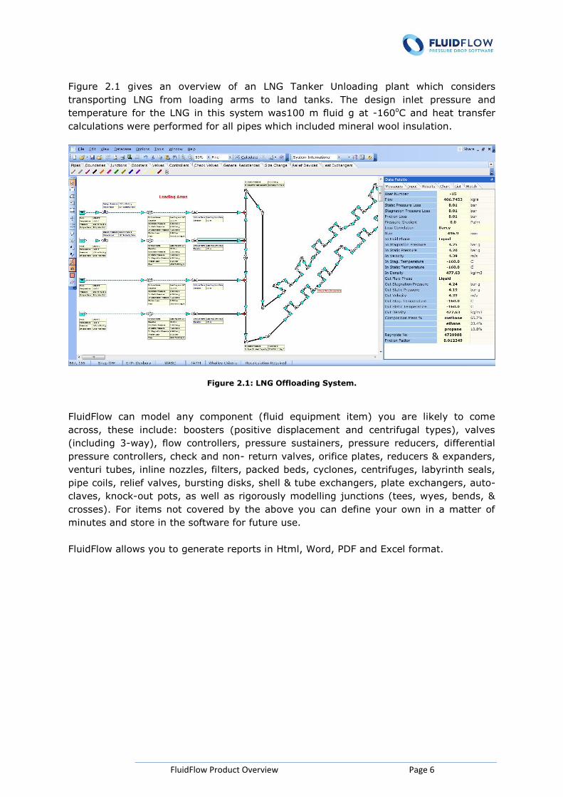
Figure 2.1 gives an overview of an LNG Tanker Unloading plant which considers
transporting LNG from loading arms to land tanks. The design inlet pressure and
temperature for the LNG in this system was100 m fluid g at -160oC and heat transfer
calculations were performed for all pipes which included mineral wool insulation.
Figure 2.1: LNG Offloading System.
FluidFlow can model any component (fluid equipment item) you are likely to come
across, these include: boosters (positive displacement and centrifugal types), valves
(including 3-way), flow controllers, pressure sustainers, pressure reducers, differential
pressure controllers, check and non- return valves, orifice plates, reducers & expanders,
venturi tubes, inline nozzles, filters, packed beds, cyclones, centrifuges, labyrinth seals,
pipe coils, relief valves, bursting disks, shell & tube exchangers, plate exchangers, auto-
claves, knock-out pots, as well as rigorously modelling junctions (tees, wyes, bends, &
crosses). For items not covered by the above you can define your own in a matter of
minutes and store in the software for future use.
FluidFlow allows you to generate reports in Html, Word, PDF and Excel format.
FluidFlow Product Overview Page 7
3 Gas Module (Compressible Flow).
The design of gas pipe flow systems can often present complex challenges for design
engineers. FluidFlow helps you overcome these challenges and accelerates your piping
system design.
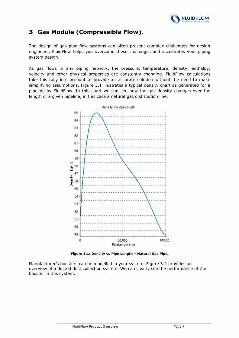
As gas flows in any piping network, the pressure, temperature, density, enthalpy,
velocity and other physical properties are constantly changing. FluidFlow calculations
take this fully into account to provide an accurate solution without the need to make
simplifying assumptions. Figure 3.1 illustrates a typical density chart as generated for a
pipeline by FluidFlow. In this chart we can see how the gas density changes over the
length of a given pipeline, in this case a natural gas distribution line.
Figure 3.1: Density vs Pipe Length – Natural Gas Pipe.
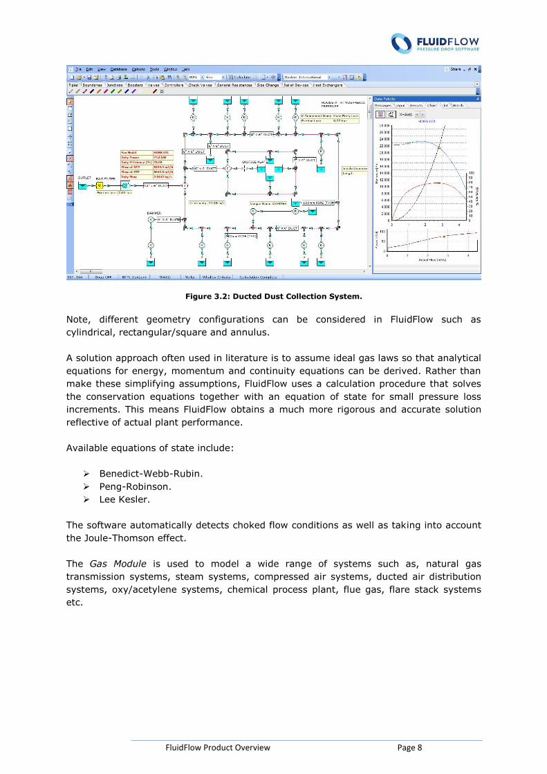
Manufacturer’s boosters can be modelled in your system. Figure 3.2 provides an
overview of a ducted dust collection system. We can clearly see the performance of the
booster in this system.
FluidFlow Product Overview Page 8
Figure 3.2: Ducted Dust Collection System.
Note, different geometry configurations can be considered in FluidFlow such as
cylindrical, rectangular/square and annulus.
A solution approach often used in literature is to assume ideal gas laws so that analytical
equations for energy, momentum and continuity equations can be derived. Rather than
make these simplifying assumptions, FluidFlow uses a calculation procedure that solves
the conservation equations together with an equation of state for small pressure loss
increments. This means FluidFlow obtains a much more rigorous and accurate solution
reflective of actual plant performance.
Available equations of state include:
Benedict-Webb-Rubin.
Peng-Robinson.
Lee Kesler.
The software automatically detects choked flow conditions as well as taking into account
the Joule-Thomson effect.
The Gas Module is used to model a wide range of systems such as, natural gas
transmission systems, steam systems, compressed air systems, ducted air distribution
systems, oxy/acetylene systems, chemical process plant, flue gas, flare stack systems
etc.
FluidFlow Product Overview Page 9
4 Two-Phase Liquid-Gas Module.
The design of two-phase pipe flow systems is often a complex phenomenon. FluidFlow is
used by engineers to calculate pressure losses and flow distribution in two-phase pipe
flow systems.
The software can be used to model fixed or changing vapor quality systems with heat
transfer included.
Calculation methods available include Lockhart-Martinelli, Friedel, Muller Steinberg and
Heck, Drift Flux, Beggs Brill or Chisholm Baroczy.
FluidFlow uses a modelling approach for the pressure loss calculation which is a hybrid
between the rigorous and empirical methods. This means the software uses well known
empirical correlations which are applied to a differential pipe length. This allows for a
flash calculation, liquid holdup and flow regime to be determined for each segment and
acknowledges that the pressure loss per unit length changes as the two-phase mixture
flows along the pipeline.
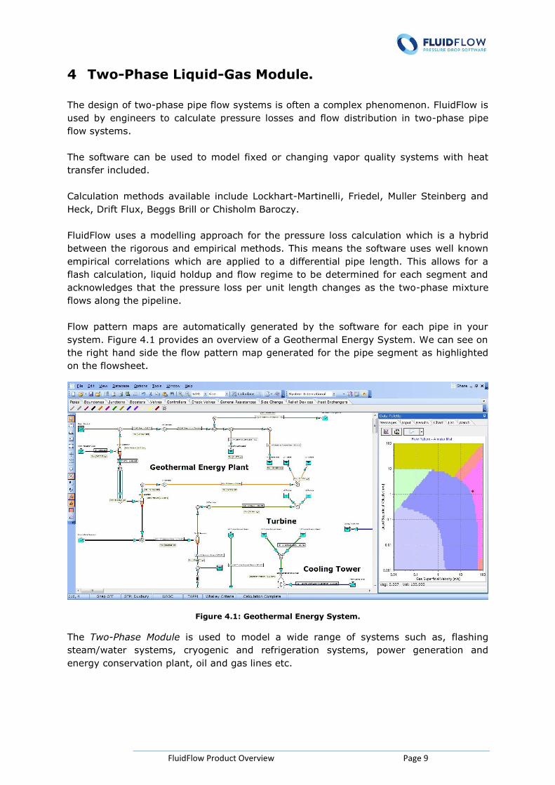
Flow pattern maps are automatically generated by the software for each pipe in your
system. Figure 4.1 provides an overview of a Geothermal Energy System. We can see on
the right hand side the flow pattern map generated for the pipe segment as highlighted
on the flowsheet.
Figure 4.1: Geothermal Energy System.
The Two-Phase Module is used to model a wide range of systems such as, flashing
steam/water systems, cryogenic and refrigeration systems, power generation and
energy conservation plant, oil and gas lines etc.
FluidFlow Product Overview Page 10
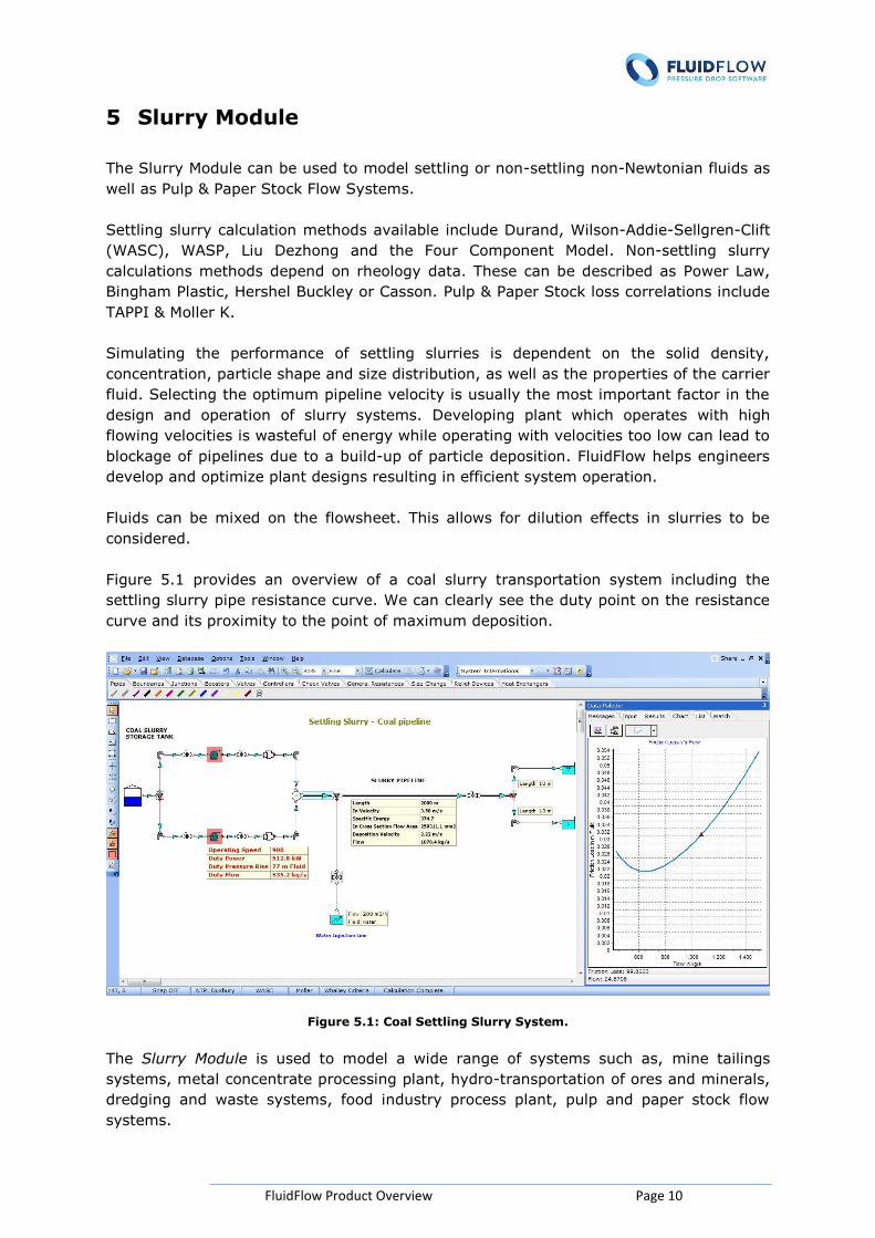
5 Slurry Module
The Slurry Module can be used to model settling or non-settling non-Newtonian fluids as
well as Pulp & Paper Stock Flow Systems.
Settling slurry calculation methods available include Durand, Wilson-Addie-Sellgren-Clift
(WASC), WASP, Liu Dezhong and the Four Component Model. Non-settling slurry
calculations methods depend on rheology data. These can be described as Power Law,
Bingham Plastic, Hershel Buckley or Casson. Pulp & Paper Stock loss correlations include
TAPPI & Moller K.
Simulating the performance of settling slurries is dependent on the solid density,
concentration, particle shape and size distribution, as well as the properties of the carrier
fluid. Selecting the optimum pipeline velocity is usually the most important factor in the
design and operation of slurry systems. Developing plant which operates with high
flowing velocities is wasteful of energy while operating with velocities too low can lead to
blockage of pipelines due to a build-up of particle deposition. FluidFlow helps engineers
develop and optimize plant designs resulting in efficient system operation.
Fluids can be mixed on the flowsheet. This allows for dilution effects in slurries to be
considered.
Figure 5.1 provides an overview of a coal slurry transportation system including the
settling slurry pipe resistance curve. We can clearly see the duty point on the resistance
curve and its proximity to the point of maximum deposition.
Figure 5.1: Coal Settling Slurry System.
The Slurry Module is used to model a wide range of systems such as, mine tailings
systems, metal concentrate processing plant, hydro-transportation of ores and minerals,
dredging and waste systems, food industry process plant, pulp and paper stock flow
systems.
FluidFlow Product Overview Page 11
6 Scripting Module - Dynamic Analysis.
The Scripting Module allows you to take your steady-state solutions a step further.
Scripting can be used to perform a wide range of dynamic simulations such as;
1. The study of tank fill/drain times based on a set of design pump operating
conditions.
2. Analyze system pressure as demands vary.
3. Investigate system control philosophies.
4. Evaluate valve performance for variable speed pumps.
5. Flare stack depressurisation.
6. Analyze scale build-up in systems and study the effect on flow rate.
7. Optimize pump and system performance.
The above is just a brief list of some of the studies which can be completed. Scripting is
a powerful tool which helps engineers optimize system performance, producing lower
operating costs and lowering carbon emissions.
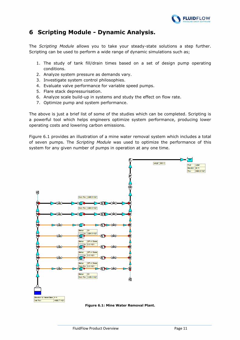
Figure 6.1 provides an illustration of a mine water removal system which includes a total
of seven pumps. The Scripting Module was used to optimize the performance of this
system for any given number of pumps in operation at any one time.
Figure 6.1: Mine Water Removal Plant.
FluidFlow Product Overview Page 12
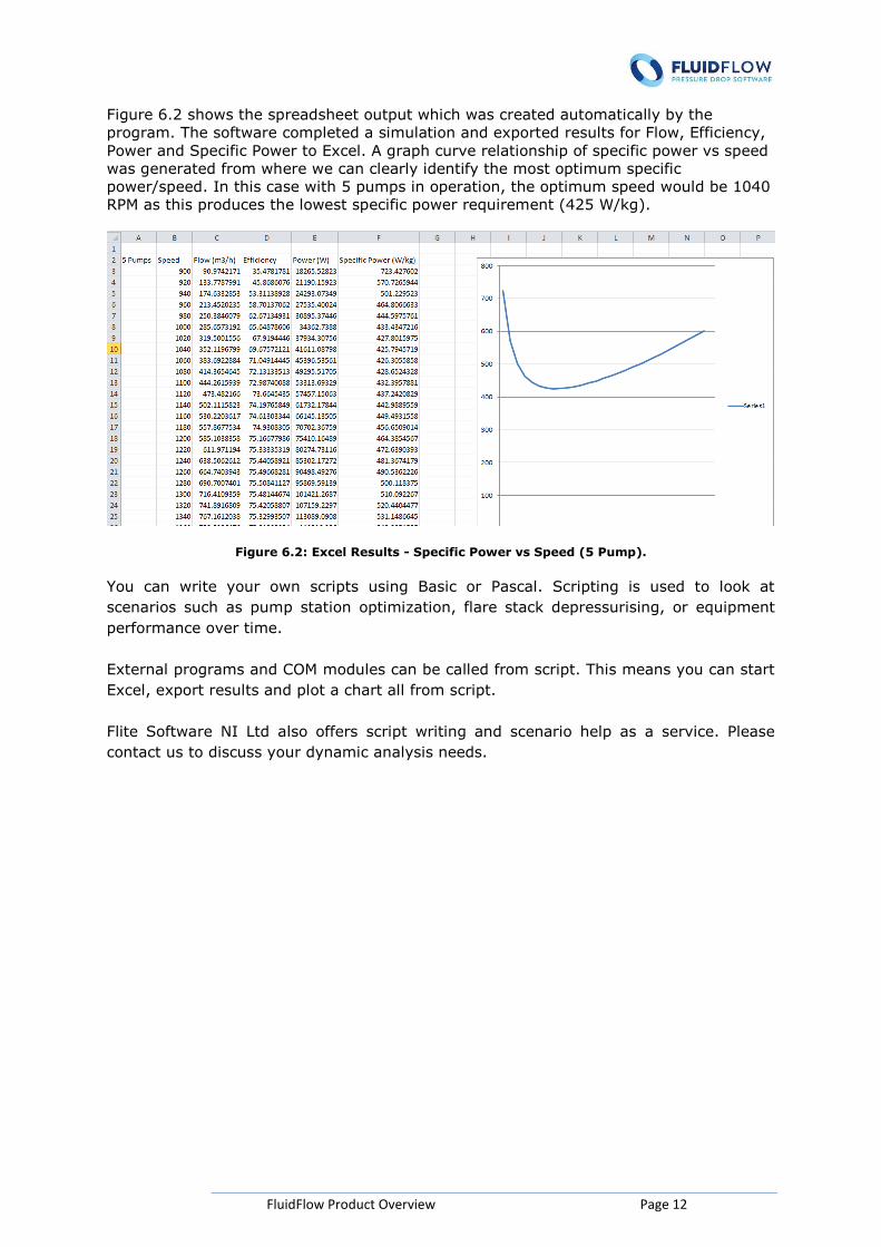
Figure 6.2 shows the spreadsheet output which was created automatically by the
program. The software completed a simulation and exported results for Flow, Efficiency,
Power and Specific Power to Excel. A graph curve relationship of specific power vs speed
was generated from where we can clearly identify the most optimum specific
power/speed. In this case with 5 pumps in operation, the optimum speed would be 1040
RPM as this produces the lowest specific power requirement (425 W/kg).
Figure 6.2: Excel Results - Specific Power vs Speed (5 Pump).
You can write your own scripts using Basic or Pascal. Scripting is used to look at
scenarios such as pump station optimization, flare stack depressurising, or equipment
performance over time.
External programs and COM modules can be called from script. This means you can start
Excel, export results and plot a chart all from script.
Flite Software NI Ltd also offers script writing and scenario help as a service. Please
contact us to discuss your dynamic analysis needs.
FluidFlow Product Overview Page 13
7 Heat Transfer
FluidFlow includes heat transfer functionality on all modules. Engineers can study heat
transfer effects at heat exchangers, pipes and junctions. The software is provided with a
library of pipe materials, insulation materials and soil types for buried pipe calculations.
FluidFlow also allows you to change insulation thickness helping you to identify the most
economic insulation thickness for your system.
Engineers can choose from a range of heat transfer options:
- Buried pipe calculations.
- Pipe heat loss/gain calculation.
- Fixed heat transfer rate.
- Fixed temperature change.
- Ignore heat loss/gain.
Our customers use FluidFlow to:
- Model shell & tube and plate heat exchangers.
- Consider effect of insulation on pipelines.
- Perform buried pipe heat transfer calculations.
- Evaluate adiabatic compression at boosters.
- Consider Joule-Thomson (J-T) effect in gas systems.
FluidFlow Product Overview Page 14
8 FluidFlow FAQ’s
How has FluidFlow been verified ?
The results generated by FluidFlow for liquids, gases, two-phase fluids and slurries are
rigorously tested and verified against published data and real-world operating systems
on a continuous basis. An extensive library of Quality Assurance test models are also
installed with the software.
As FluidFlow is continuously undergoing development, each new version of the software
is benchmarked using the above procedures.
FluidFlow has been used successfully in industry since it was first launched 1984. The
software has undergone extensive development since first launched ensuring the product
is up to date, includes the very latest solution technology and offers engineers a fast and
effective design simulation tool.
Quality Assurance is an integral part of our business ethic. From our software design
approach through to our released product, FluidFlow is developed to the highest quality
and standard.
Flite Software Ltd is an ISO9001:2008 registered company.
Can FluidFlow be used to model heat transfer in piping systems ?
Yes. All FluidFlow modules are provided with heat transfer functionality - As Standard.
This includes the ability to perform pipe heat loss calculations whilst taking into account
the effect of local wind speed, surface emissivity & ambient temperature.
A library of pipe insulation materials is provided with the software As Standard and you
can select the required thickness for each pipe. Convection, conduction and radiation
losses are calculated automatically. This means FluidFlow can be used to quickly
optimize energy use by selecting the economic insulation thickness.
When performing heat loss calculations, Engineers can choose to enter a U value or allow
the software calculate this parameter.
The software also allows engineers to analyze the effect of a fixed temperature change
or energy transfer rate across a pipe or fitting. FluidFlow completes an energy balance
throughout all piping systems.
FluidFlow can model shell and tube exchangers, plate heat exchangers, coils and
autoclaves.
FluidFlow Product Overview Page 15
Can FluidFlow be used to model a non-Newtonian fluid ?
Yes. The Slurry module allows you to choose from the following non-Newtonian fluid
models;
Bingham Plastic
Herschel Bulkley
Power Law
Casson
Engineers can create a new non-Newtonian fluid by either entering the shear rate vs
shear stress relationship or directly define the fluid constants. This data is readily
available from fluid rheology data.
Can FluidFlow be used to model a settling slurry ?
Yes. FluidFlow includes five pressure loss correlations for modelling settling slurry piping
systems. Unique to FluidFlow is the ability to model slurries which exhibit a combination
of settling and non-settling slurry flow behaviour. This means Engineers don’t have to
make the difficult choice of modelling a slurry as either settling or non-settling when in
fact it may exhibit properties of both flow regimes.
Users can choose from a total of five correlations when modelling settling slurry systems.
When developing the model, the software will enunciate warning messages to assist the
engineer in developing an efficient system design. This includes messages identifying the
risk of saltation or, pipe blockage.
FluidFlow inlcudes three options for analyzing the pump performance derating.
Can FluidFlow be used to model Fire Protection Systems ?
Yes. FluidFlow includes a proprietary fire sprinkler and hydrant node and includes a
comprehensive database of components - As Standard. Additional sprinklers can be
added to the database by either entering a single nominal K value or entering the flow vs
pressure loss relationship and additional hydrants can also be added by either entering a
single K value or a pressure loss relationship of % open vs Kv/Cv.
Note, when defining either of the above items using a pressure loss relationship,
FluidFlow automatically generates the curve-fit.
Can I create a Template File in FluidFlow ?
Yes. Users can generate template files such as pump stations and valve stations from
v3.3. These templates can be stored and inserted into any model in the future. This
promotes rapid model development.
Do I have to enter the model into each module separately ?
No. The software uses a single user-interface meaning any model can be calculated
using any of the Modules available.
Can FluidFlow be used to model Pressure Relief Valves & Bursting Disks?
FluidFlow Product Overview Page 16
Yes. From version 3.3 onwards, users can automatically size relief valves and bursting
disks for liquid, gas, steam and two-phase systems to both API & ISO standards. When
using the API method, FluidFlow also suggests the most appropriate standard API size
for your consideration.
The software also allows you to model specific manufacturer’s relief valves and is
provided with a library of relief valve models - As Standard. Engineers can expand the
library of relief valves by adding new models as and when required.
Can I model closed-loop systems ?
Yes. FluidFlow has been used successfully by our customers to model closed-loop piping
systems such as sea water cooling systems. When modeling this system type, the
software takes into account that the pressure, velocity and elevation of the inlet and
outlet are identical and therefore, the changes in static, velocity and elevation pressures
are zero.
Can I model pipe inclination/elevation changes ?
Yes. Pipe inclination is determined by the software based on the elevation data entered
for each junction on the Input Inspector. This applies to liquids, gases, two-phase fluids
and slurries.
Can I model non-standard fittings ?
Yes. FluidFlow includes a proprietary component for modeling the pressure loss
relationship of any non-standard pipe/duct fitting.
Can I close-off or isolate sections of a model ?
Yes. Simply select the relevant pipes and fittings in the model and set the Status to Off
or Closed from the Input Inspector. When you recalculate your model, you will notice
that flow does not occur in these sections of the model.
Can I add pumps to the database ?
Yes. The software is provided with a library of Centrifugal, PD and Rotating PD Pumps.
Engineers can expand the library by adding new pump models as and when required. It
should be noted that, when adding a new pump to the database, you are only required
to do so once. The pump will then be stored in the database and shall be available for all
future design/modeling projects.
Can I apply pump affinity laws ?
Yes. FluidFlow allows you to model the effect of changing the pump operating speed or
impeller diameter. The software automatically applies the affinity laws and will determine
the effect on duty pressure rise, efficiency, power requirement and NPSHr.
This is an extremely powerful tool and is used frequently by users to optimize the
operating performance and energy consumption of centrifugal pumps.
FluidFlow Product Overview Page 17
Can I add fans or compressors to the database ?
Yes. The software is provided with a library of fans and compressors. Engineers can
expand the library by adding new models as and when required. It should be noted that,
when adding a new fan or compressor to the database, you are only required to do so
once. The component will then be stored in the database and shall be available for all
future design/modeling projects.
Can I model control valves ?
Yes. FluidFlow is provided with a library of pressure, flow and differential pressure
control valves. Users have the option of expanding the library by adding new valves
when required. The software will automatically determine the Cv/Kv and corresponding
valve position (% open). Furthermore, the software will enunciate a warning message if
the valve position is outside the allowable range of good practice procedures.
The flow rate, system pressure, velocity etc is automatically determined by the software
for all control valves.
Can I model the effect of partially closing isolating/throttling valves ?
Yes. Users can enter a % open on the Input Inspector for all manual valves. FluidFlow
will then determine the corresponding K value and associated pressure loss for the valve.
When changing the % opening of the valve, the software will determine the effect on
flow rate, pressure, velocity etc.
Can I model PD Pumps ?
Yes. The software is provided with a library of PD Pumps and Rotating PD Pumps.
Engineers can expand the library by adding new pump models as and when required. It
should be noted that, when adding a new pump to the database, you are only required
to do so once. The pump will then be stored in the database and shall be available for all
future design/modeling projects.
Can I plot composite pump curves ?
Yes. Composite pump capacity curves can be developed for pumps installed in both
series and parallel. This provides a powerful method of communicating your system
design and pump performance data.
Can I plot Energy & Hydraulic Grade Lines ?
Yes. Energy & Hydraulic Grade Lines can be plotted for your system. This graph plot
provides a useful representation of the level of energy in the system. This also helps
engineers quickly identify any potential trouble-spots.
This tool has been used effectively and successfully to model and troubleshoot piping
systems transporting fluid/slurry over considerable distances using multiple centrifugal
pumps in series. The graph plot clearly identified regions of low pressure and enabled
the engineering teams to optimize the positioning of the pumps and the individual pump
performance.

FluidFlow Product Overview Page 18
Can I model ductwork ?
Yes. Simply select the duct on the flowsheet and set the geometry of the duct on the
Input Inspector to Rectangular/Square. Users can then enter the height and width of the
ductwork.
Can FluidFlow detect choked flow conditions ?
Yes. FluidFlow will detect sonic choking and endpoint choking, highlight the node on the
flowsheet where this has occurred and enunciate a warning to this effect.
Contact us at:
Flite Software NI Ltd Block E
Balliniska Business Park Springtown Road
Derry Northern Ireland
BT48 0LY
T: +44 2871 279 227 F: +44 2871 279 806
www.fluidflowinfo.com