Embed Size (px)
Citation preview
Dr Ajay N Phirke
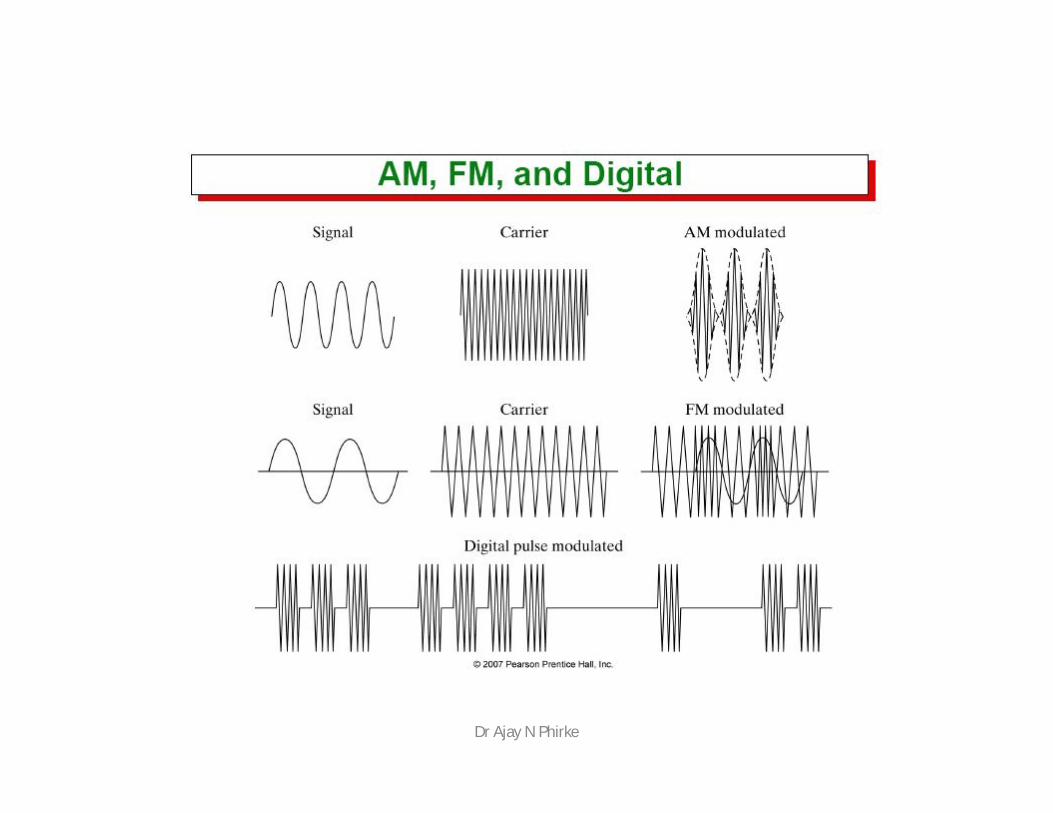
• Communication systems with light as the carrierand optical fiber as communication medium
• Optical fiber is used to contain and guide lightwaves
– Typically made of glass or plastic– Propagation of light in atmosphere is
impractical• This is similar to cable guiding electromagnetic
waves• Capacity comparison
– Microwave at 10 GHz– Light at 100 Tera Hz (1014 )
Dr Ajay N Phirke
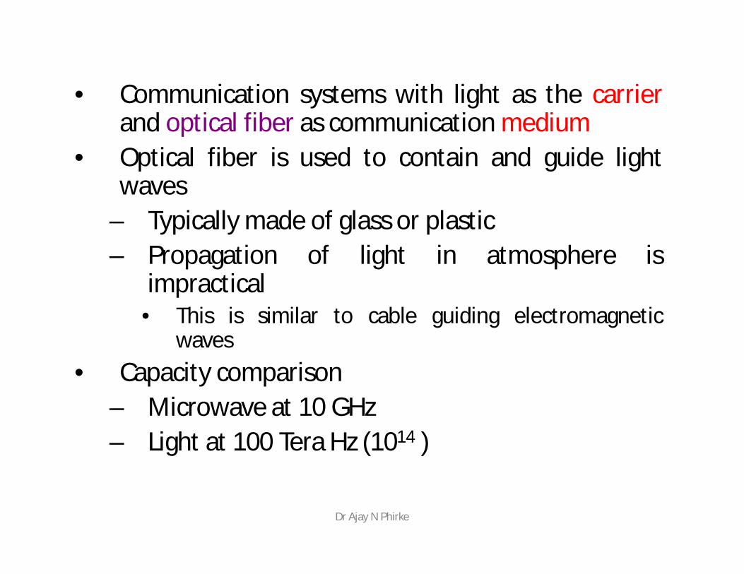
• 1880 Alexander G. Bell– Photo phone, transmit sound waves over beam
of light • 1930: TV image through uncoated fiber cables
– Few years later image through a single glass fiber• 1951: Flexible fiberscope: Medical applications• 1956: The term “fiber optics” used for the first
time• 1958: Paper on Laser & Maser
History
Dr Ajay N Phirke
• 1960: Laser invented• 1967: New Communications medium: cladded
fiber• 1960s: Extremely lossy fiber:
– More than 1000 dB /km• 1970: Corning Glass Work NY, Fiber with loss of
less than 2 dB/km• 70s & 80s : High quality sources and detectors• Late 80s : Loss as low as 0.16 dB/km• 1990: Deployment of SONET
(Synchronous Optical Network, a standard for connectingfiber-optic transmission systems )
Dr Ajay N Phirke
• Long distance signal transmission (over 100 km)
• Large bandwidth, light weight and small diameter
• Long length (2,4, 12 km)• Easy installation and upgrades• No conductivity• Security• Designed for future applications needs
Dr Ajay N Phirke
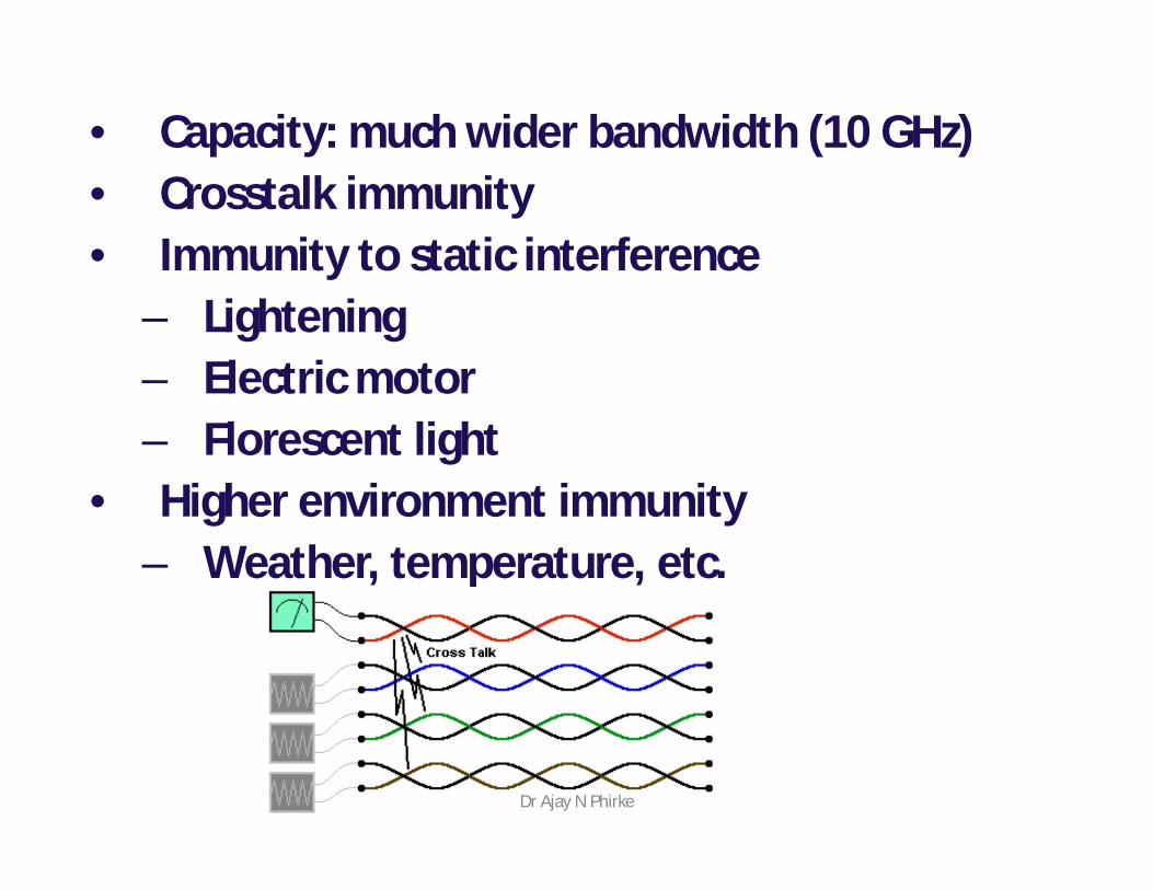
• Capacity: much wider bandwidth (10 GHz) • Crosstalk immunity• Immunity to static interference
– Lightening– Electric motor – Florescent light
• Higher environment immunity– Weather, temperature, etc.
Dr Ajay N Phirke
Disadvantages• Higher initial cost in installation• Interfacing cost• Strength
– Lower tensile strength
• Remote electric power• More expensive to repair/maintain
– Tools: Specialized and sophisticated
Dr Ajay N Phirke
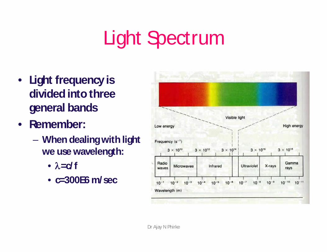
• Light frequency is divided into three general bands
• Remember:– When dealing with light
we use wavelength: • l=c/f • c=300E6 m/sec
Light Spectrum
Dr Ajay N Phirke
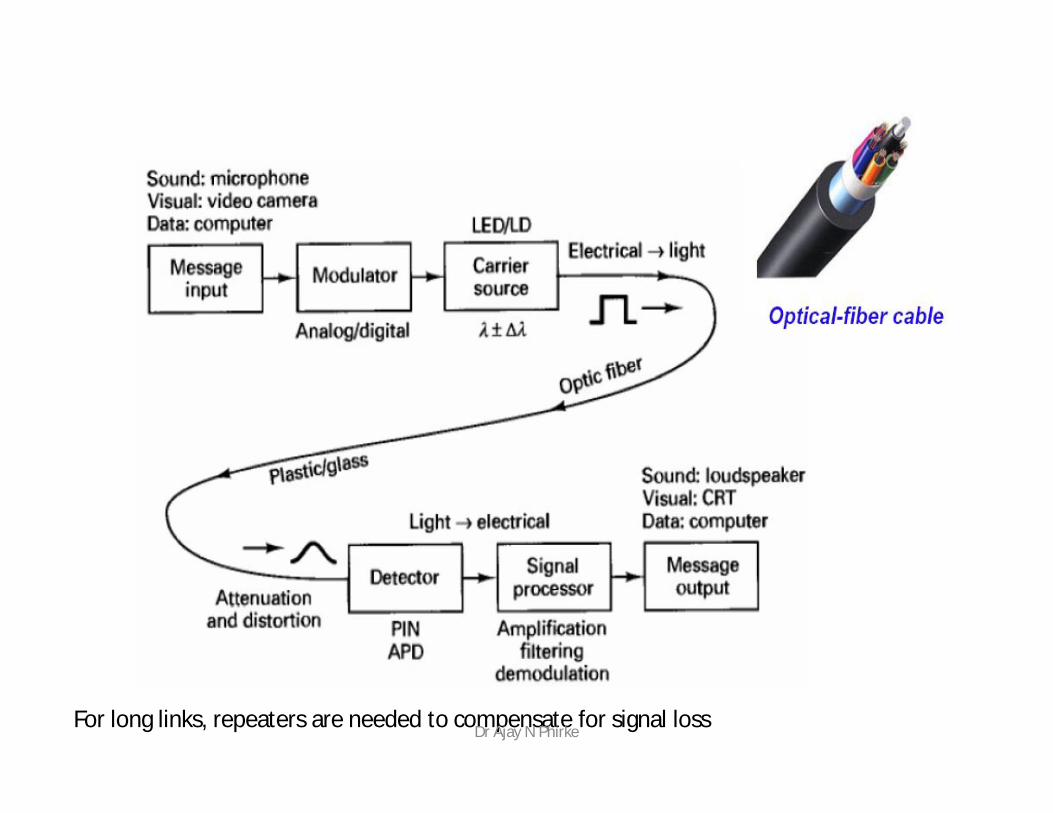
For long links, repeaters are needed to compensate for signal lossDr Ajay N Phirke
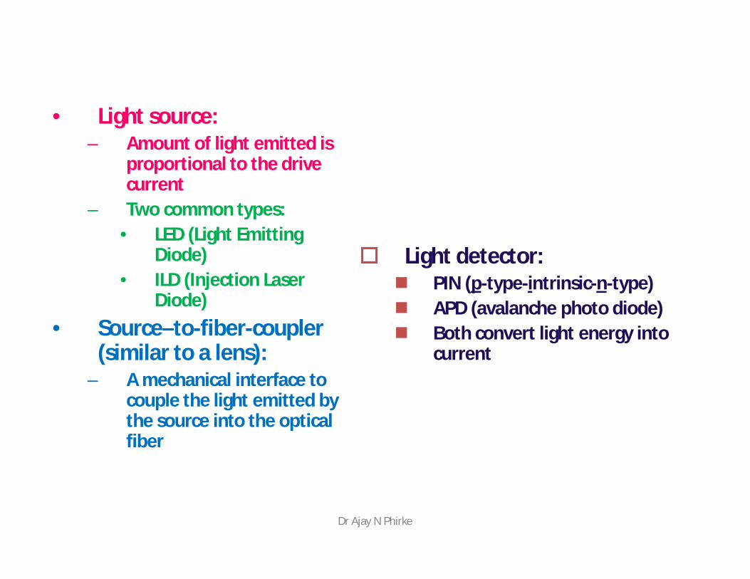
• Light source: – Amount of light emitted is
proportional to the drive current
– Two common types: • LED (Light Emitting
Diode)• ILD (Injection Laser
Diode)• Source–to-fiber-coupler
(similar to a lens):– A mechanical interface to
couple the light emitted by the source into the optical fiber
Light detector: PIN (p-type-intrinsic-n-type) APD (avalanche photo diode) Both convert light energy into
current
Dr Ajay N Phirke

Plastic jacketGlass or plasticcladdingFiber core
Dr Ajay N Phirke
Dr Ajay N Phirke
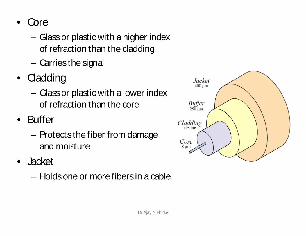
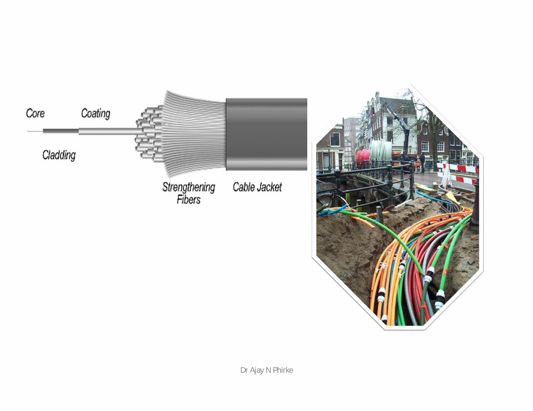
• Core– Glass or plastic with a higher index
of refraction than the cladding– Carries the signal
• Cladding– Glass or plastic with a lower index
of refraction than the core
• Buffer– Protects the fiber from damage
and moisture
• Jacket– Holds one or more fibers in a cable
Dr Ajay N Phirke
• Plastic core and cladding• Glass core with plastic cladding PCS
(Plastic-Clad Silicon)• Glass core and glass cladding SCS:
Silica-clad silica• Under research: non silicate: Zinc-
chloride – 1000 time as efficient as glass
Dr Ajay N Phirke
Plastic Fiber
• Used for short distances • Higher attenuation, but easy to install• Better withstand stress• Less expensive• 60% less weight
Dr Ajay N Phirke
Glass fibers :The glass fibers are generally fabricated byfusing mixtures of metal oxides and silicaglasses.
Silica has a refractive index of 1.458 at 850nm. To produce two similar materials havingslightly different indices of refraction for thecore and cladding, either fluorine or variousoxides such as B2O3, GeO2 or P2O3 are addedto silica.Examples:
SiO2 core; P2O3 – SiO2 cladding GeO2 – SiO2 core; SiO2 claddingP2O5 – SiO2 core; SiO2 cladding
Dr Ajay N Phirke
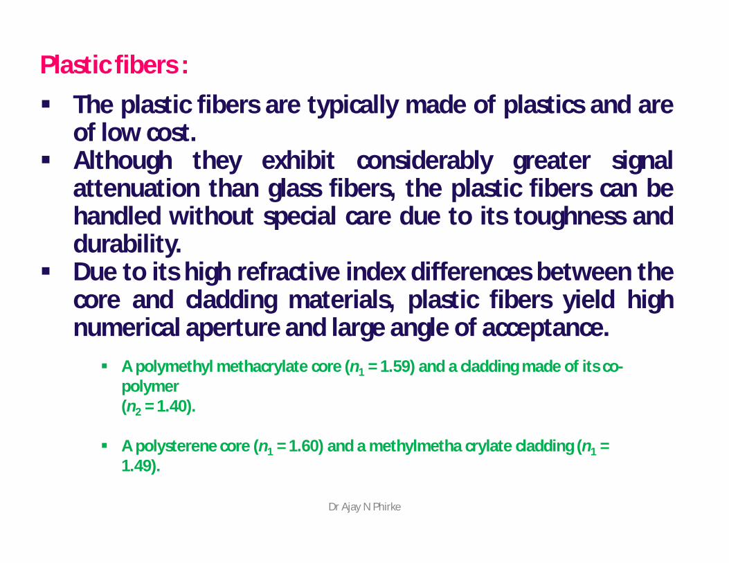
Plastic fibers : The plastic fibers are typically made of plastics and are
of low cost. Although they exhibit considerably greater signal
attenuation than glass fibers, the plastic fibers can behandled without special care due to its toughness anddurability.
Due to its high refractive index differences between thecore and cladding materials, plastic fibers yield highnumerical aperture and large angle of acceptance. A polymethyl methacrylate core (n1 = 1.59) and a cladding made of its co-
polymer (n2 = 1.40).
A polysterene core (n1 = 1.60) and a methylmetha crylate cladding (n1 = 1.49).
Dr Ajay N Phirke
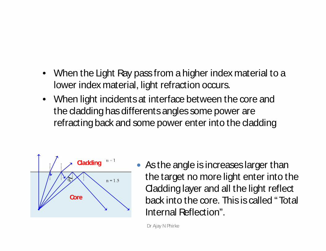
• When the Light Ray pass from a higher index material to a lower index material, light refraction occurs.
• When light incidents at interface between the core and the cladding has differents angles some power are refracting back and some power enter into the cladding
As the angle is increases larger thanthe target no more light enter into theCladding layer and all the light reflectback into the core. This is called “Total Internal Reflection”.
Core
Cladding
Dr Ajay N Phirke
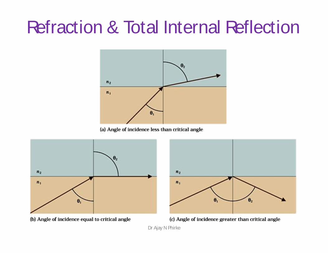
Refraction & Total Internal Reflection
Dr Ajay N Phirke
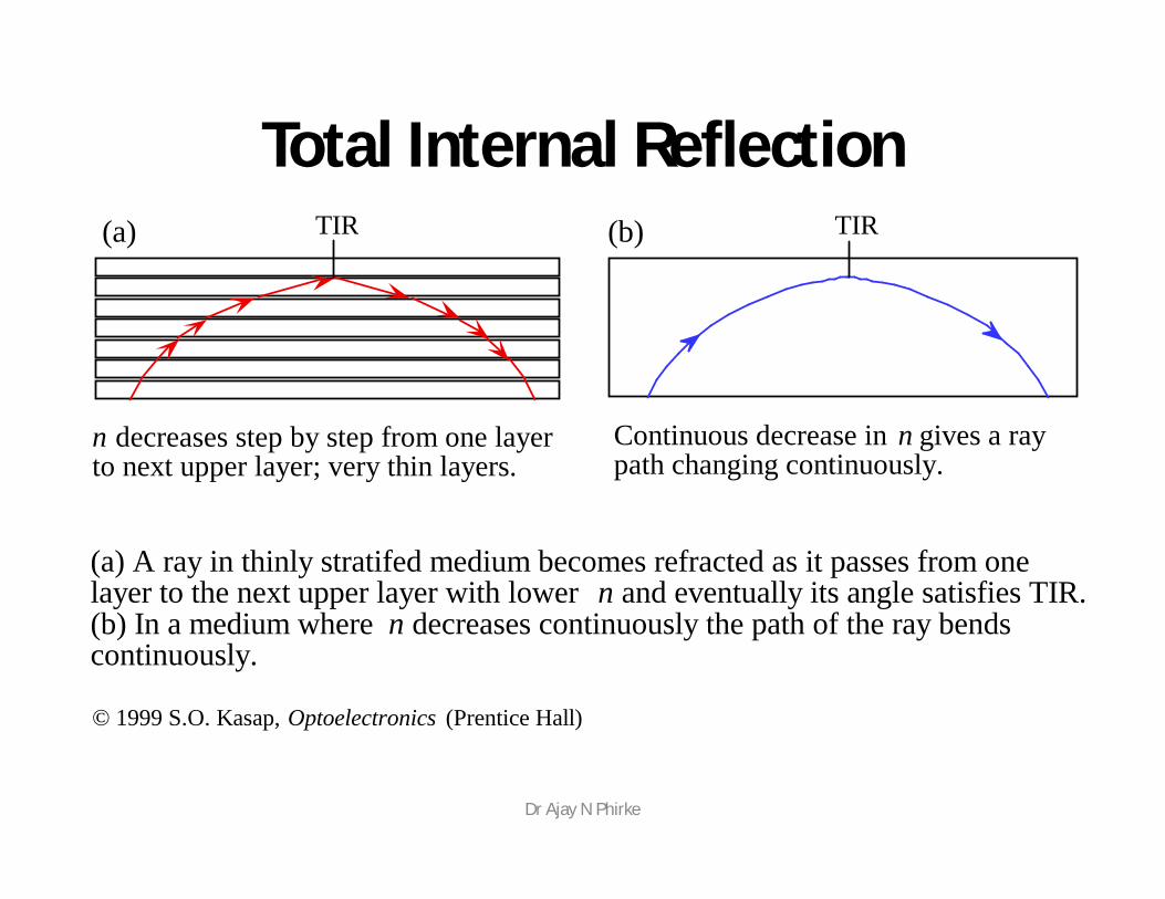
n decreases step by step from one layerto next upper layer; very thin layers.
Continuous decrease in n gives a raypath changing continuously.
TIR TIR
(a) A ray in thinly stratifed medium becomes refracted as it passes from onelayer to the next upper layer with lower n and eventually its angle satisfies TIR.(b) In a medium where n decreases continuously the path of the ray bendscontinuously.
(a) (b)
© 1999 S.O. Kasap, Optoelectronics (Prentice Hall)
Total Internal Reflection
Dr Ajay N Phirke
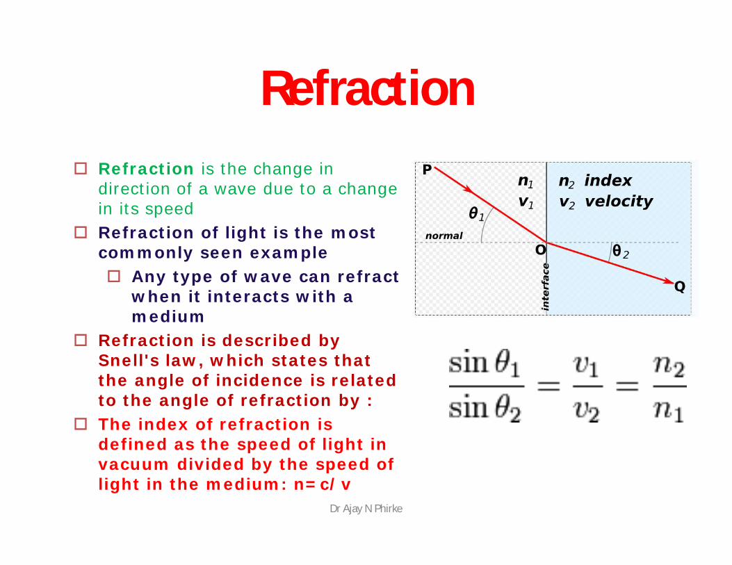
Refraction Refraction is the change in
direction of a wave due to a change in its speed
Refraction of light is the most commonly seen example Any type of wave can refract
when it interacts with a medium
Refraction is described by Snell's law, which states that the angle of incidence is related to the angle of refraction by :
The index of refraction is defined as the speed of light in vacuum divided by the speed of light in the medium: n=c/v
Dr Ajay N Phirke

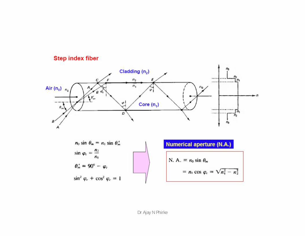
Numerical Aperture
• The numerical aperture of the fiber is closely related to the critical angle and is often used in the specification for optical fiber and the components that work with it
• The numerical aperture is given by the formula:
•
The Numerical Aperture (NA) is a measure of how much light can be collected by an optical system such as an optical fibre or a microscope lens.
The NA is related to the acceptance angle a, which indicates the size of a cone of light that can be accepted by the fibre.
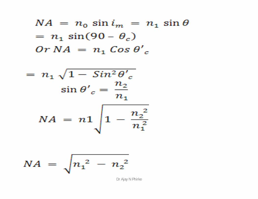
NA = naSin a = (n12 – n2
2)1/2
Where n1 = refractive index of core n2 = refractive index of cladding na = refractive index of air (1.00)
Dr Ajay N Phirke
cladding
n1
n2
core
n2
cladding
air
a
n2
n1
core
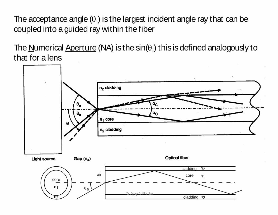
The acceptance angle (i) is the largest incident angle ray that can be coupled into a guided ray within the fiber
The Numerical Aperture (NA) is the sin(i) this is defined analogously to that for a lens
Dr Ajay N Phirke

Consider an optical fibre having a core of refractive index n1 and cladding of refractiveindex n2.let the incident light makes an angle i with the core axis as shown in figure .Then the light gets refracted at an angle θ and fall on the core-cladding interface at anangle where,
By Snell’s law at the point of entrance of light in to the optical fiber we get,
Dr Ajay N Phirke
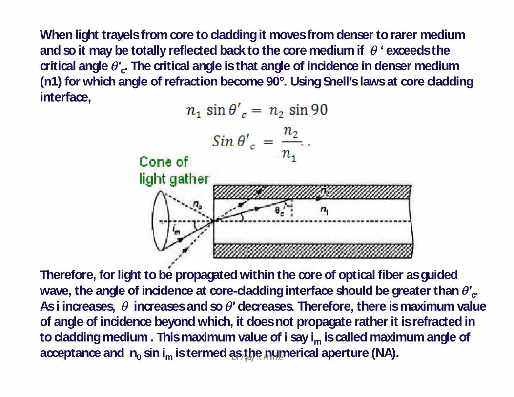
When light travels from core to cladding it moves from denser to rarer medium and so it may be totally reflected back to the core medium if ‘ exceeds the critical angle 'c. The critical angle is that angle of incidence in denser medium (n1) for which angle of refraction become 90°. Using Snell’s laws at core cladding interface,
or
Therefore, for light to be propagated within the core of optical fiber as guided wave, the angle of incidence at core-cladding interface should be greater than 'c. As i increases, increases and so ' decreases. Therefore, there is maximum value of angle of incidence beyond which, it does not propagate rather it is refracted in to cladding medium . This maximum value of i say im is called maximum angle of acceptance and n0 sin im is termed as the numerical aperture (NA).Dr Ajay N Phirke
Dr Ajay N Phirke

Fiber Types
• Modes of operation (the path which the light is traveling on)
• Index profile –Step –Graded
Dr Ajay N Phirke
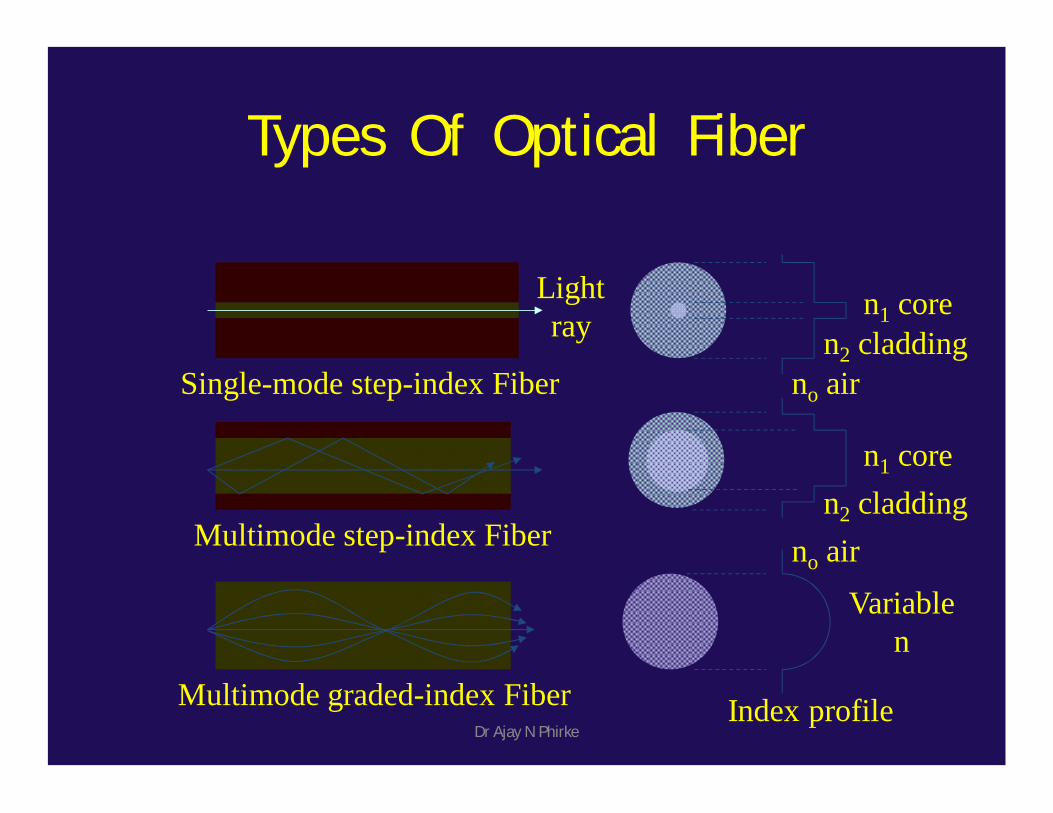
Types Of Optical Fiber
Single-mode step-index Fiber
Multimode step-index Fiber
Multimode graded-index Fiber
n1 coren2 cladding
no air
n2 claddingn1 core
Variablen
no air
Lightray
Index profileDr Ajay N Phirke
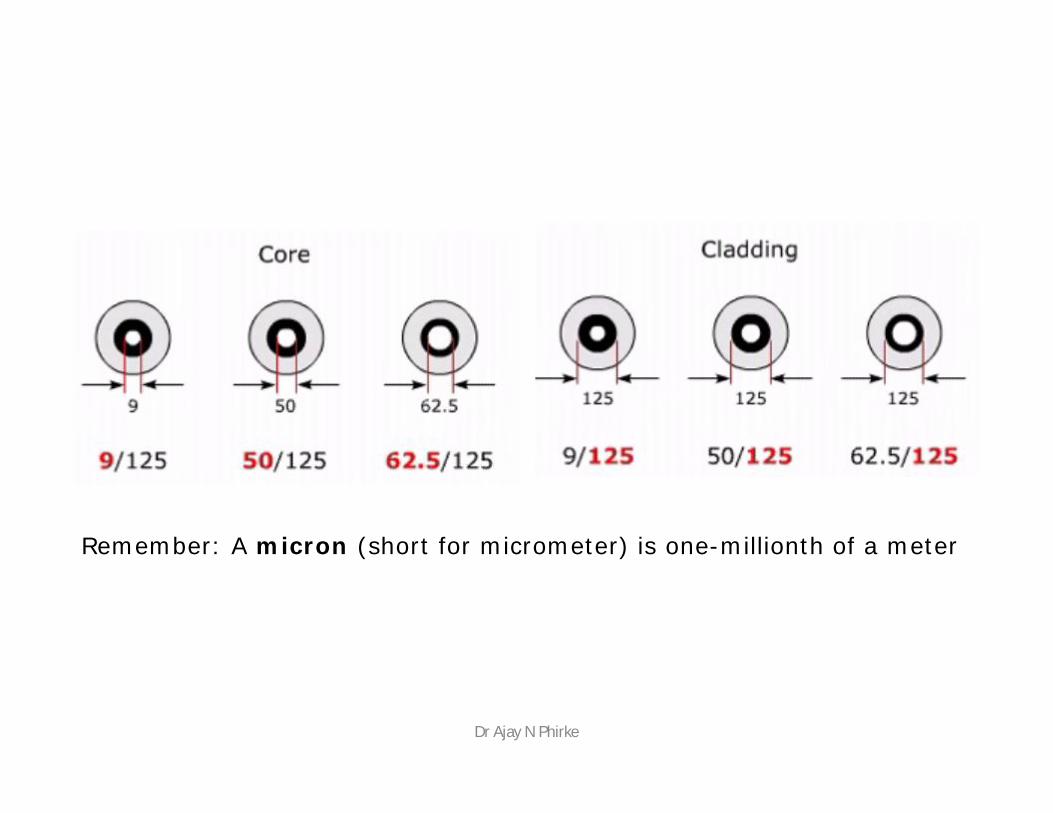
Remember: A micron (short for micrometer) is one-millionth of a meter
Dr Ajay N Phirke
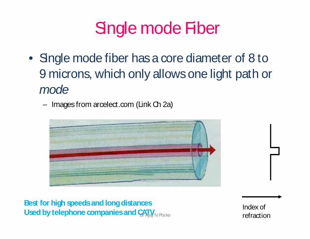
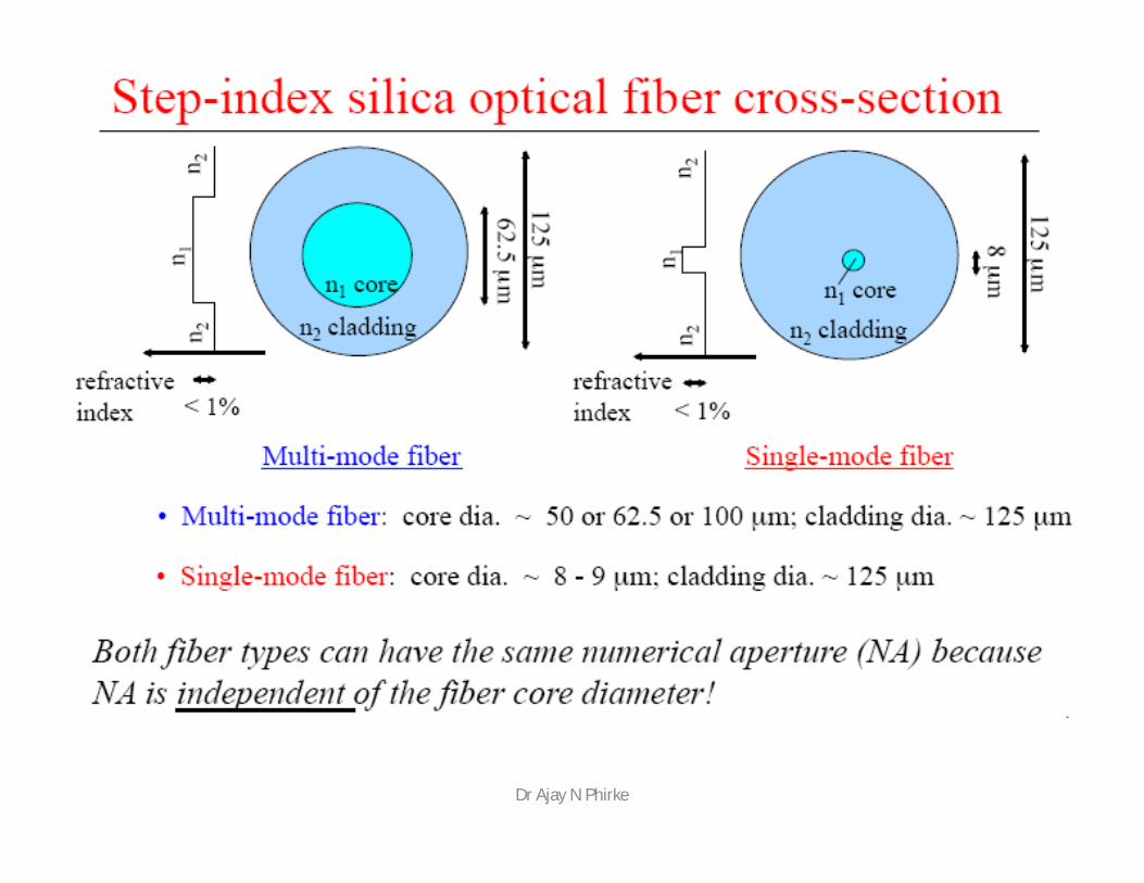
Single mode Fiber
• Single mode fiber has a core diameter of 8 to 9 microns, which only allows one light path or mode– Images from arcelect.com (Link Ch 2a)
Index of refraction
Best for high speeds and long distancesUsed by telephone companies and CATVDr Ajay N Phirke
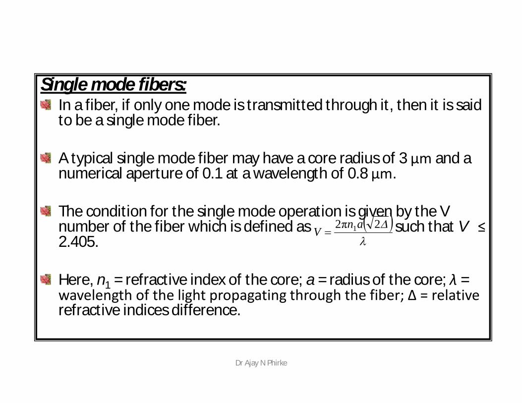
Single mode fibers:In a fiber, if only one mode is transmitted through it, then it is said to be a single mode fiber.
A typical single mode fiber may have a core radius of 3 μm and a numerical aperture of 0.1 at a wavelength of 0.8 μm.
The condition for the single mode operation is given by the V number of the fiber which is defined as such that V ≤2.405.
Here, n1 = refractive index of the core; a = radius of the core; λ = wavelength of the light propagating through the fiber; Δ = relative refractive indices difference.
2π2 1anV
Dr Ajay N Phirke
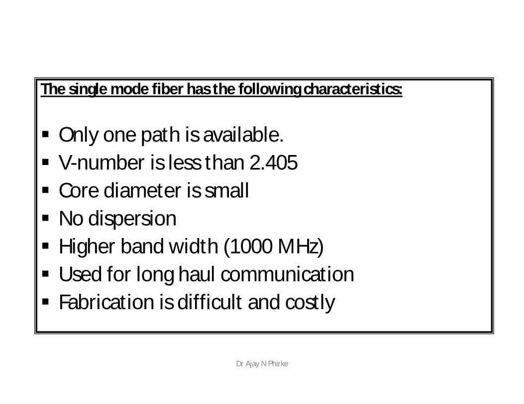
The single mode fiber has the following characteristics:
Only one path is available. V-number is less than 2.405 Core diameter is small No dispersion Higher band width (1000 MHz) Used for long haul communication Fabrication is difficult and costly
Dr Ajay N Phirke
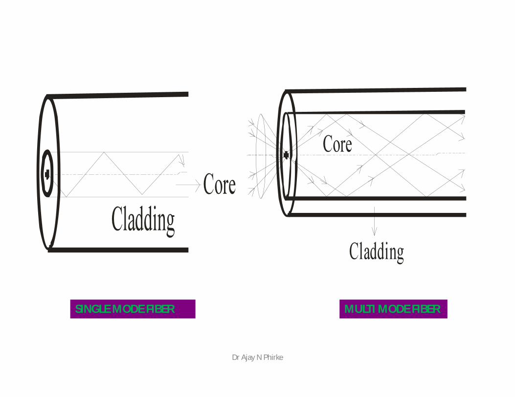
SINGLE MODE FIBER MULTI MODE FIBER
Dr Ajay N Phirke
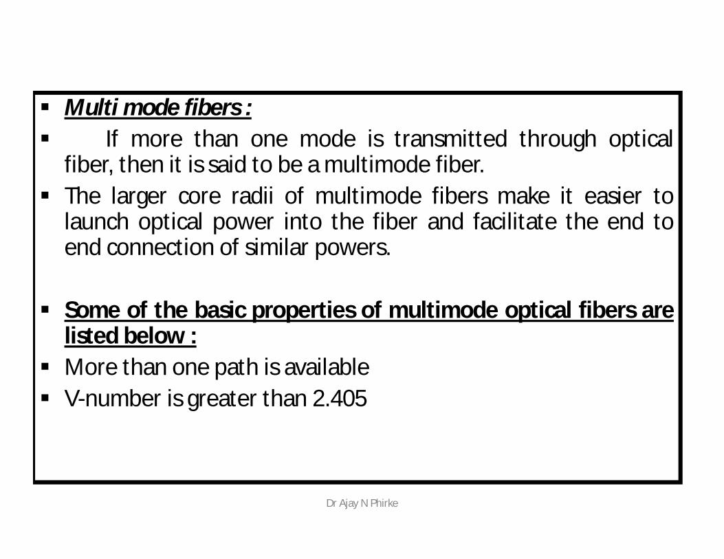
Multi mode fibers : If more than one mode is transmitted through optical
fiber, then it is said to be a multimode fiber. The larger core radii of multimode fibers make it easier to
launch optical power into the fiber and facilitate the end toend connection of similar powers.
Some of the basic properties of multimode optical fibers arelisted below :
More than one path is available V-number is greater than 2.405
Dr Ajay N Phirke
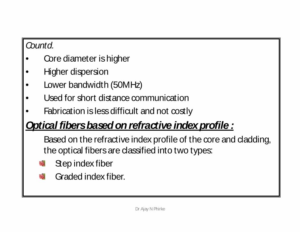
Countd.• Core diameter is higher• Higher dispersion• Lower bandwidth (50MHz)• Used for short distance communication• Fabrication is less difficult and not costly
Optical fibers based on refractive index profile :Based on the refractive index profile of the core and cladding, the optical fibers are classified into two types:
Step index fiberGraded index fiber.
Dr Ajay N Phirke
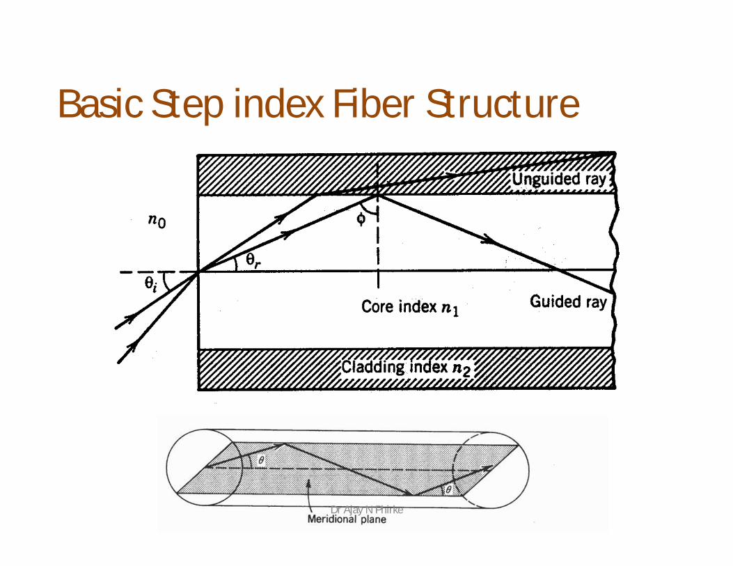
Basic Step index Fiber Structure
Dr Ajay N Phirke
Step index fiber : In a step index fiber, the refractive index changes in a
step fashion, from the centre of the fiber, the core, tothe outer shell, the cladding.
It is high in the core and lower in the cladding. The lightin the fiber propagates by bouncing back and forthfrom core-cladding interface.
The step index fibers propagate both single andmultimode signals within the fiber core.
The light rays propagating through it are in the form ofmeridinal rays which will cross the fiber core axisduring every reflection at the core – cladding boundaryand are propagating in a zig – zag manner.
Dr Ajay N Phirke
Step index single mode fibers : The light energy in a single-mode fiber is
concentrated in one mode only. This is accomplished by reducing and or the core
diameter to a point where the V is less than 2.4. In other words, the fiber is designed to have a V number
between 0 and 2.4. This relatively small value means that the fiber radius
and , the relative refractive index difference, must be small.
No intermodal dispersion exists in single mode fibers because only one mode exists.
Dr Ajay N Phirke
Contd.• With careful choice of material, dimensions and l,
the total dispersion can be made extremely small,less than 0.1 ps /(km nm), making this fibersuitable for use with high data rates.
• In a single-mode fiber, a part of the light propagatesin the cladding.
• The cladding is thick and has low loss.• Typically, for a core diameter of 10 m, the cladding
diameter is about 120 m.• Handling and manufacturing of single mode step
index fiber is more difficult.
Dr Ajay N Phirke
Step Index single mode (10 / 70)Characteristics• Very small core diameter• Low numerical aperture• Low attenuation• Very High Bandwidth• Very high capacity• Very expensive• Need laser as a sourceAppl: Sea cable
Dr Ajay N Phirke
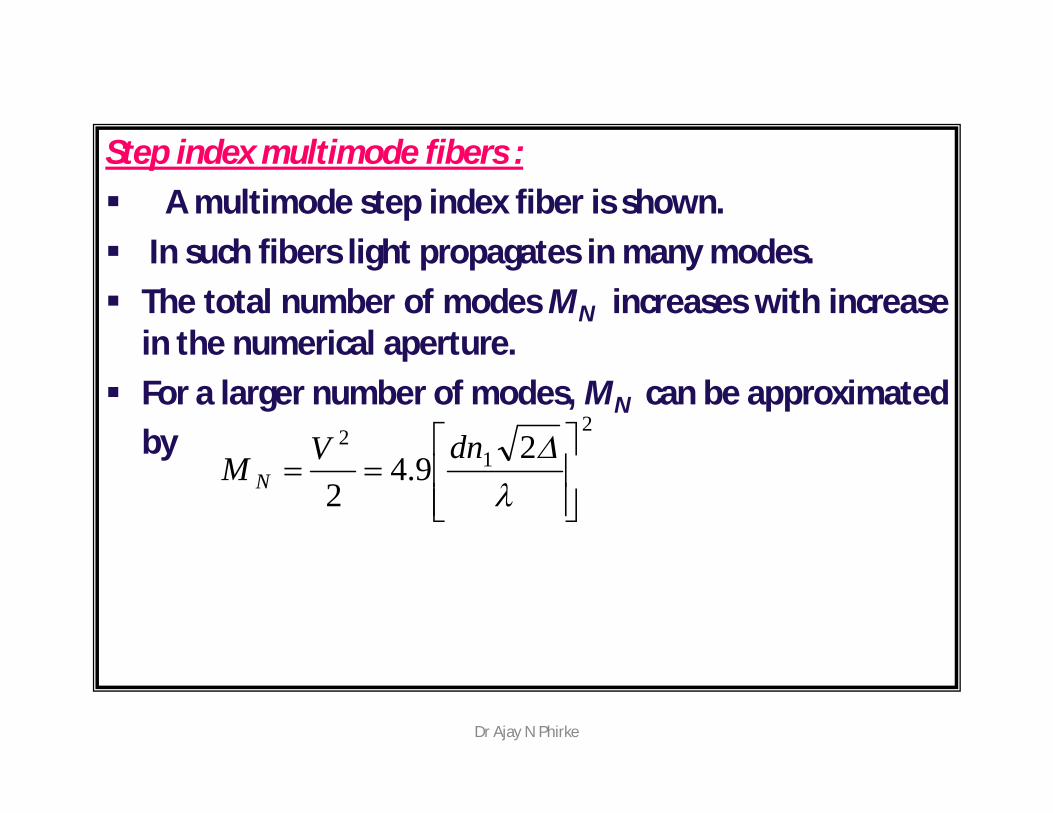
Step index multimode fibers : A multimode step index fiber is shown. In such fibers light propagates in many modes. The total number of modes MN increases with increase
in the numerical aperture. For a larger number of modes, MN can be approximated
by2
12 2
9.42
dnVM N
Dr Ajay N Phirke
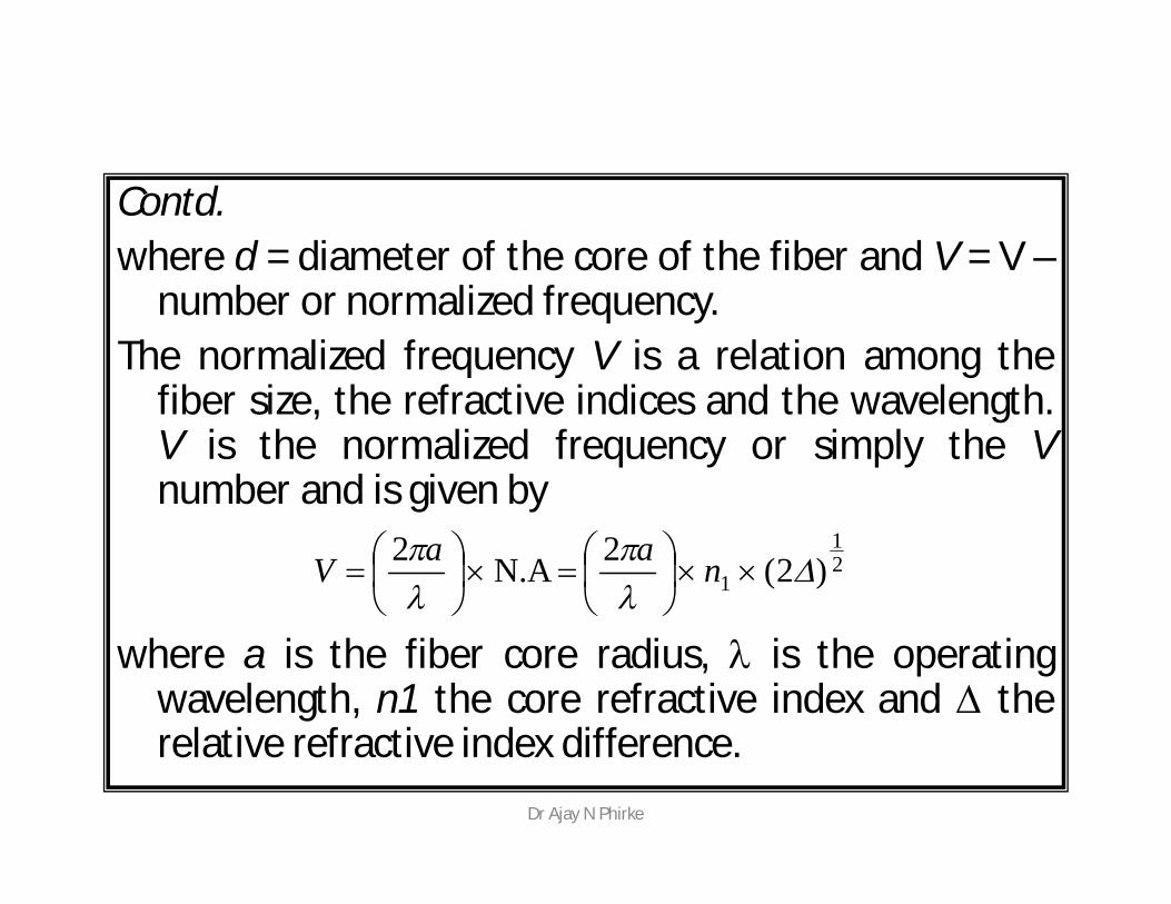
Contd.where d = diameter of the core of the fiber and V = V –
number or normalized frequency.The normalized frequency V is a relation among the
fiber size, the refractive indices and the wavelength.V is the normalized frequency or simply the Vnumber and is given by
where a is the fiber core radius, is the operatingwavelength, n1 the core refractive index and therelative refractive index difference.
21
1 )2(2 N.A 2
naaV
Dr Ajay N Phirke
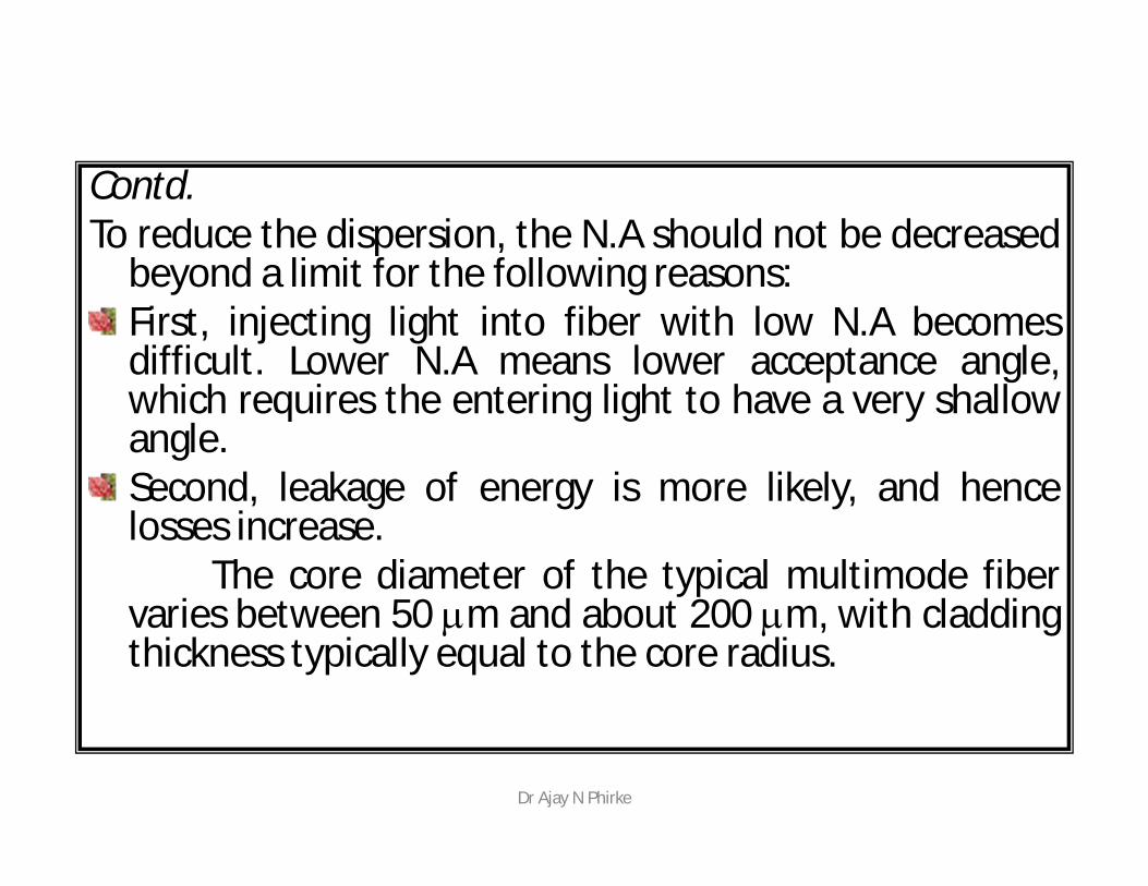
Contd.To reduce the dispersion, the N.A should not be decreased
beyond a limit for the following reasons:First, injecting light into fiber with low N.A becomesdifficult. Lower N.A means lower acceptance angle,which requires the entering light to have a very shallowangle.Second, leakage of energy is more likely, and hencelosses increase.
The core diameter of the typical multimode fibervaries between 50 m and about 200 m, with claddingthickness typically equal to the core radius.
Dr Ajay N Phirke
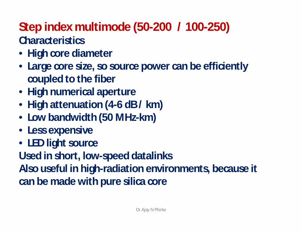
Step index multimode (50-200 / 100-250)Characteristics• High core diameter• Large core size, so source power can be efficiently
coupled to the fiber• High numerical aperture• High attenuation (4-6 dB / km)• Low bandwidth (50 MHz-km)• Less expensive• LED light sourceUsed in short, low-speed datalinksAlso useful in high-radiation environments, because it can be made with pure silica core
Dr Ajay N Phirke
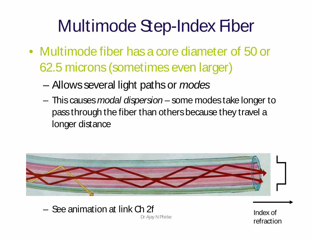
Multimode Step-Index Fiber• Multimode fiber has a core diameter of 50 or
62.5 microns (sometimes even larger)– Allows several light paths or modes– This causes modal dispersion – some modes take longer to
pass through the fiber than others because they travel a longer distance
– See animation at link Ch 2f Index of refraction
Dr Ajay N Phirke
Graded index fibers : In graded index fiber the refractive index n in the
core varies as we move away from the centre. The refractive index of the core is made to vary in
the form of parabolic manner such that themaximum refractive index is present at the centre ofthe core.
Dr Ajay N Phirke
Contd. Each dashed circle represents a different refractive
index, decreasing as we move away from the fibercenter.
A ray incident on these boundaries between na – nb,nb – nc etc., is refracted.
Eventually at n2 the ray is turned around and totallyreflected.
Dr Ajay N Phirke
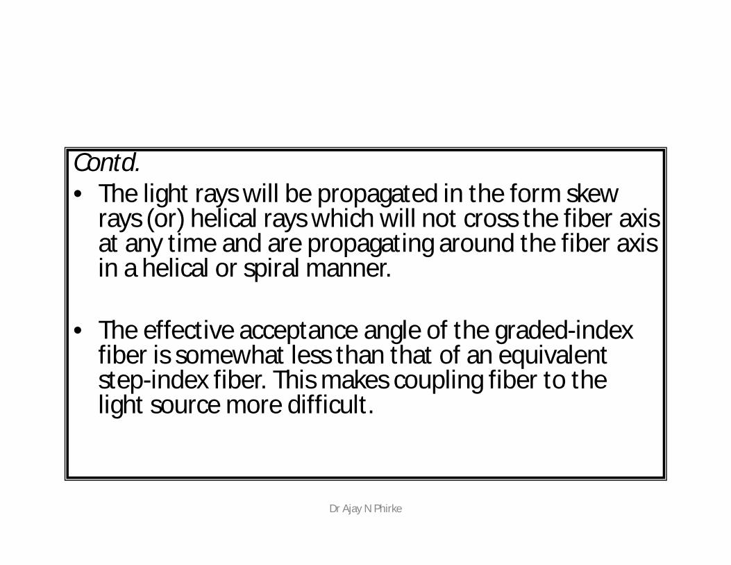
Contd.• The light rays will be propagated in the form skew
rays (or) helical rays which will not cross the fiber axis at any time and are propagating around the fiber axis in a helical or spiral manner.
• The effective acceptance angle of the graded-index fiber is somewhat less than that of an equivalent step-index fiber. This makes coupling fiber to the light source more difficult.
Dr Ajay N Phirke
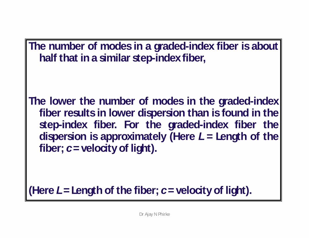
The number of modes in a graded-index fiber is abouthalf that in a similar step-index fiber,
The lower the number of modes in the graded-indexfiber results in lower dispersion than is found in thestep-index fiber. For the graded-index fiber thedispersion is approximately (Here L = Length of thefiber; c = velocity of light).
(Here L = Length of the fiber; c = velocity of light).
Dr Ajay N Phirke
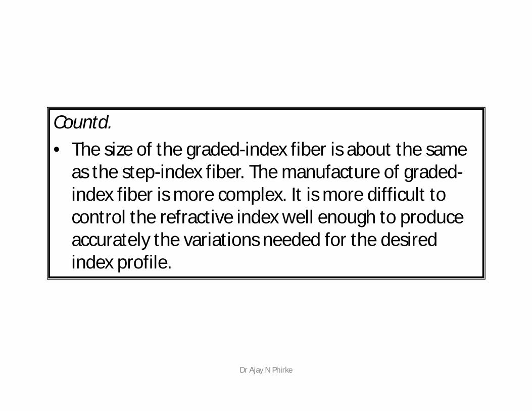
Countd.• The size of the graded-index fiber is about the same
as the step-index fiber. The manufacture of graded-index fiber is more complex. It is more difficult to control the refractive index well enough to produce accurately the variations needed for the desired index profile.
Dr Ajay N Phirke
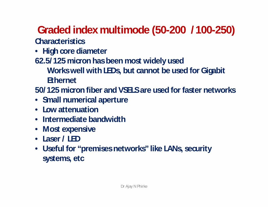
Graded index multimode (50-200 /100-250)Characteristics• High core diameter62.5/125 micron has been most widely used
Works well with LEDs, but cannot be used for Gigabit Ethernet
50/125 micron fiber and VSELS are used for faster networks• Small numerical aperture• Low attenuation• Intermediate bandwidth• Most expensive• Laser / LED• Useful for “premises networks” like LANs, security
systems, etc
Dr Ajay N Phirke
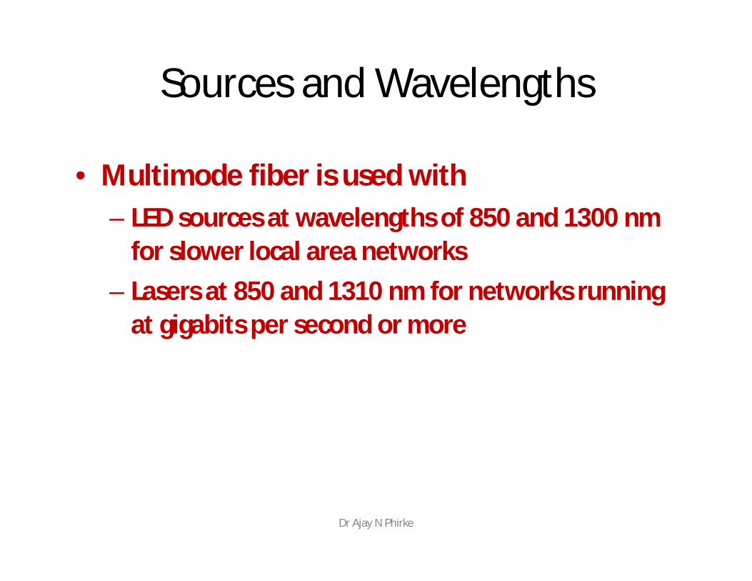
Sources and Wavelengths
• Multimode fiber is used with– LED sources at wavelengths of 850 and 1300 nm
for slower local area networks– Lasers at 850 and 1310 nm for networks running
at gigabits per second or more
Dr Ajay N Phirke
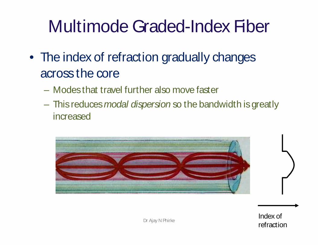
Multimode Graded-Index Fiber
• The index of refraction gradually changes across the core– Modes that travel further also move faster– This reduces modal dispersion so the bandwidth is greatly
increased
Index of refraction
Dr Ajay N Phirke
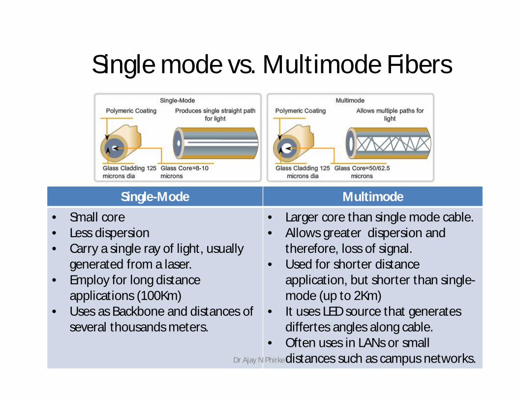
Single mode vs. Multimode Fibers
Single-Mode Multimode• Small core• Less dispersion• Carry a single ray of light, usually
generated from a laser.• Employ for long distance
applications (100Km)• Uses as Backbone and distances of
several thousands meters.
• Larger core than single mode cable.• Allows greater dispersion and
therefore, loss of signal. • Used for shorter distance
application, but shorter than single-mode (up to 2Km)
• It uses LED source that generatesdiffertes angles along cable.
• Often uses in LANs or smalldistances such as campus networks. Dr Ajay N Phirke
Single-mode step-index Fiber
Advantages:• Minimum dispersion: all rays take same path, same time to travel down
the cable. A pulse can be reproduced at the receiver very accurately.• Less attenuation, can run over longer distance without repeaters.• Larger bandwidth and higher information rate
Disadvantages:• Difficult to couple light in and out of the tiny core• Highly directive light source (laser) is required• Interfacing modules are more expensive
Dr Ajay N Phirke
Multi Mode
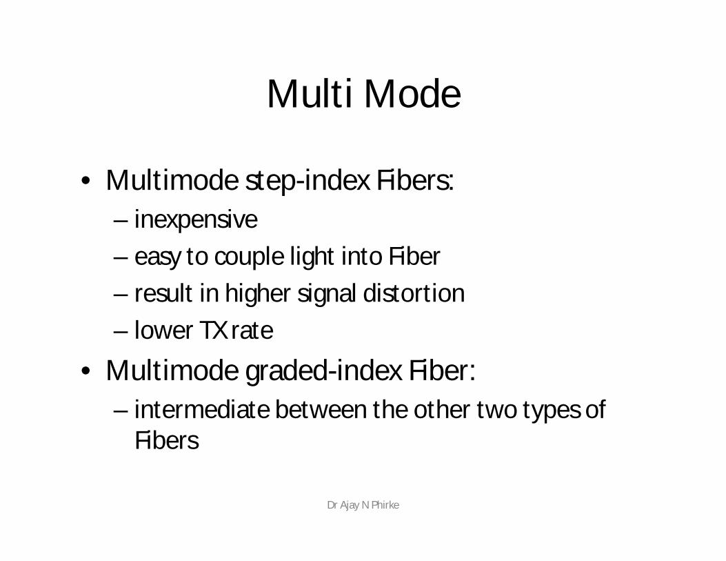
• Multimode step-index Fibers:– inexpensive– easy to couple light into Fiber– result in higher signal distortion– lower TX rate
• Multimode graded-index Fiber:– intermediate between the other two types of
Fibers
Dr Ajay N Phirke
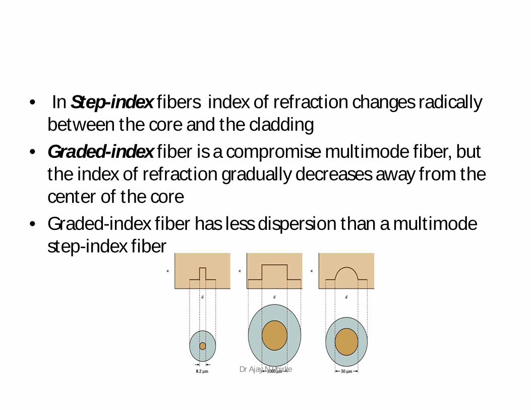
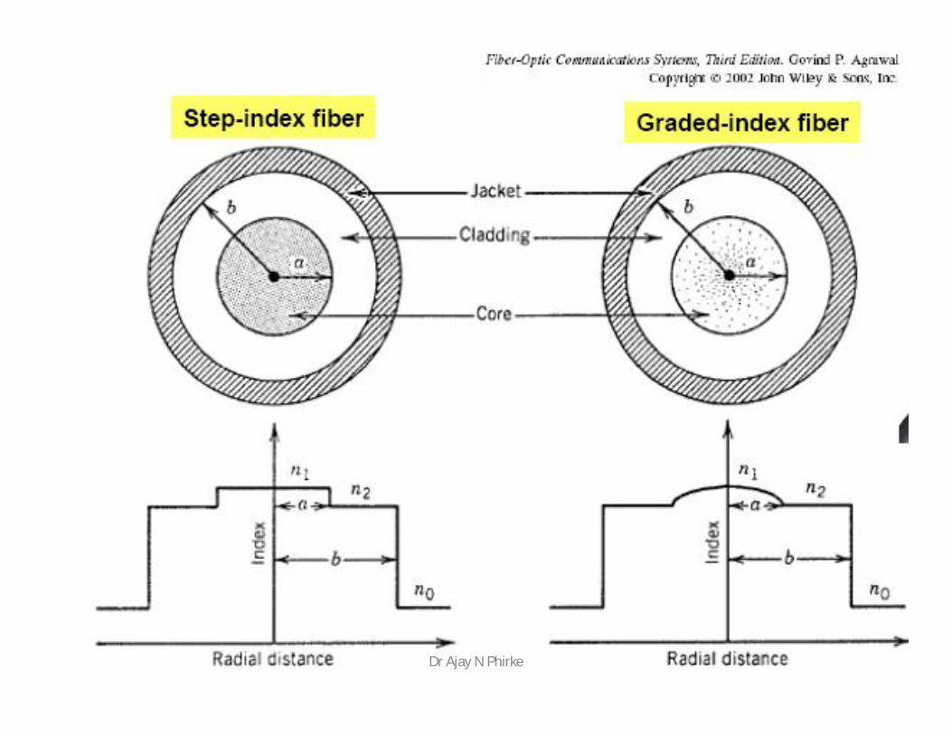
• In Step-index fibers index of refraction changes radically between the core and the cladding
• Graded-index fiber is a compromise multimode fiber, but the index of refraction gradually decreases away from the center of the core
• Graded-index fiber has less dispersion than a multimode step-index fiber
Dr Ajay N Phirke
Dr Ajay N Phirke
Step-index and Graded-index
• Step index multimode was developed first, but rare today because it has a low bandwidth (50 MHz-km)
• It has been replaced by graded-index multimode with a bandwidth up to 2 GHz-km
Dr Ajay N Phirke
Dr Ajay N Phirke
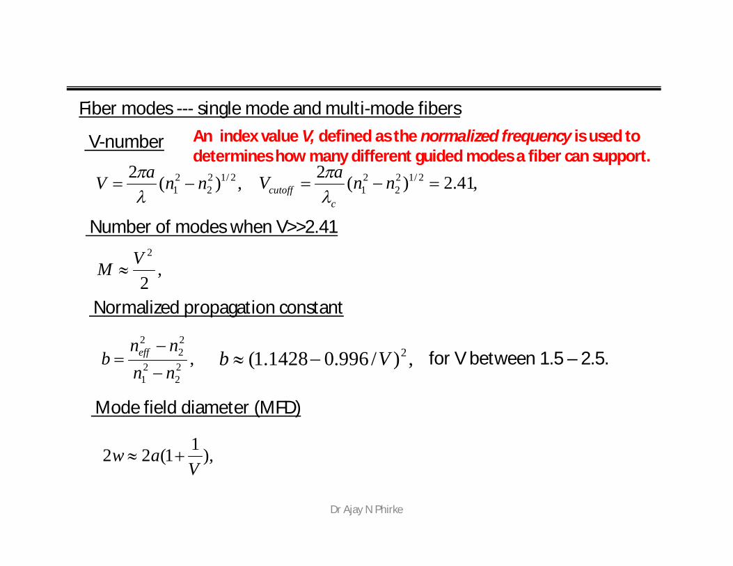
Fiber modes --- single mode and multi-mode fibers
V-number
,22
21
22
2
nnnn
b eff
,)/996.01428.1( 2Vb
,)(2 2/122
21 nnaV
,41.2)(2 2/12
221 nnaV
ccutoff
Number of modes when V>>2.41
,2
2VM
Normalized propagation constant
for V between 1.5 – 2.5.
Mode field diameter (MFD)
),11(22V
aw
An index value V, defined as the normalized frequency is used to determines how many different guided modes a fiber can support.
Dr Ajay N Phirke

Waveguide calculation of FiberMode
• Here is fiber mode calculation based on Waveguide Calculation by Fiber Optics for Sale Company (USA)
• V number determines the numbers of guided modes.
• When V number is smaller than2.405 only one mode can be guided by the fiber, this is calledsingle mode fiber.
• When V Numer is larger than2.405 severals modes can be guided by the fiber.
• As higer V number as largernumber of modes, this is calledMultimode Fiber
Dr Ajay N Phirke
Plastic Optical Fiber
• Large core (1 mm) step-index multimode fiber
• Easy to cut and work with, but high attenuation (1 dB / meter) makes it useless for long distances
Dr Ajay N Phirke
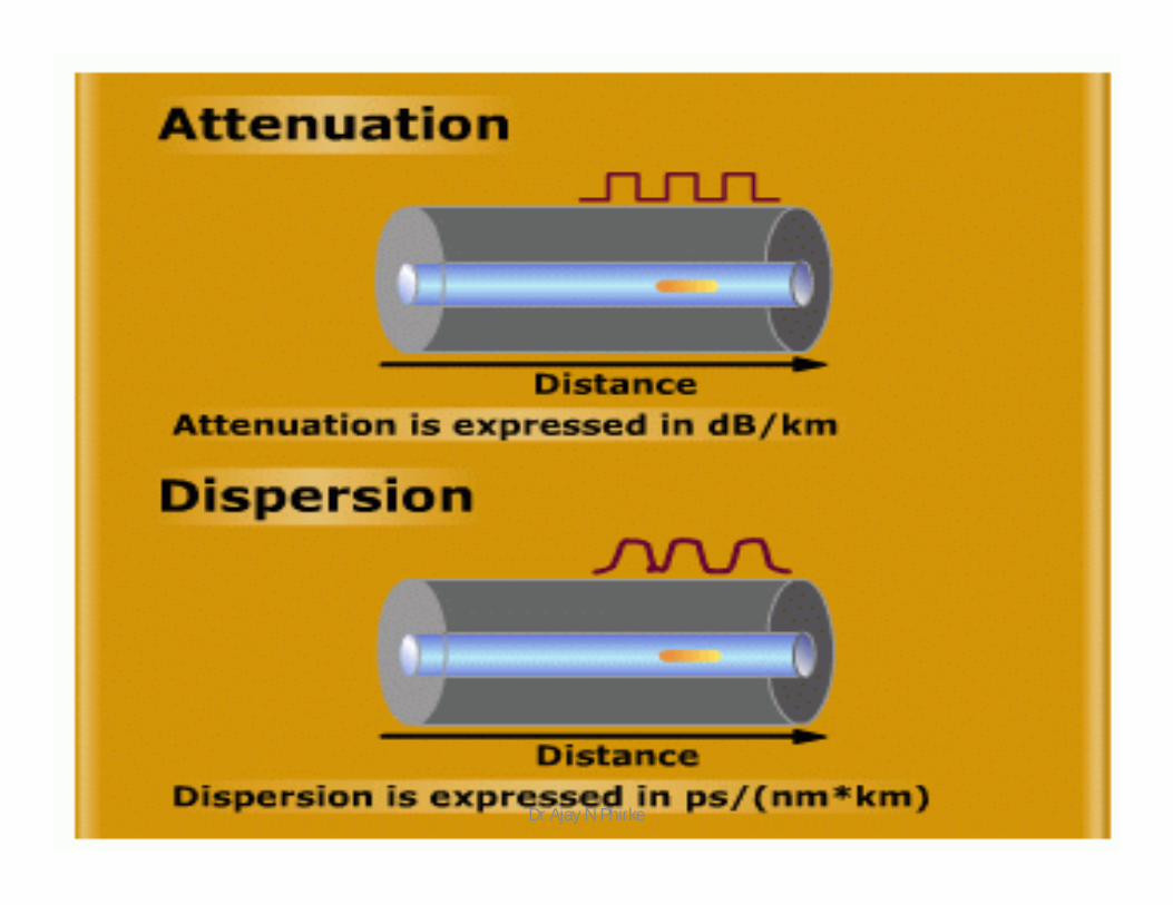
Fiber Optic Specifications• Attenuation
– Loss of signal, measured in dB
• Dispersion– Blurring of a signal, affects bandwidth
• Bandwidth– The number of bits per second that can be sent
through a data link
• Numerical Aperture– Measures the largest angle of light that can be
accepted into the coreDr Ajay N Phirke
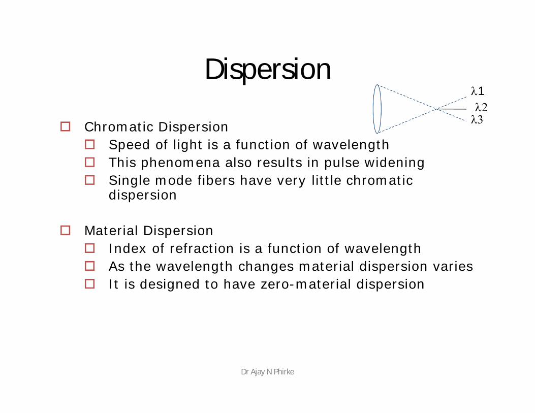
Dispersion
Chromatic Dispersion Speed of light is a function of wavelength This phenomena also results in pulse widening Single mode fibers have very little chromatic
dispersion
Material Dispersion Index of refraction is a function of wavelength As the wavelength changes material dispersion varies It is designed to have zero-material dispersion
123
Dr Ajay N Phirke
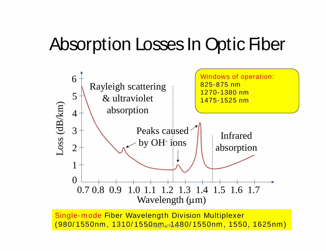
Absorption Losses In Optic FiberLo
ss (d
B/k
m)
100.7 0.8
Wavelength (m)0.9 1.0 1.1 1.2 1.3 1.4 1.5 1.6 1.7
2
3
4
5
6
Peaks causedby OH- ions
Infraredabsorption
Rayleigh scattering& ultravioletabsorption
Single-mode Fiber Wavelength Division Multiplexer(980/1550nm, 1310/1550nm, 1480/1550nm, 1550, 1625nm)
Windows of operation: 825-875 nm 1270-1380 nm1475-1525 nm
Dr Ajay N Phirke
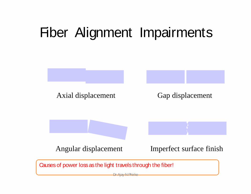
Fiber Alignment Impairments
Axial displacement Gap displacement
Angular displacement Imperfect surface finish
Causes of power loss as the light travels through the fiber! Dr Ajay N Phirke
Areas of Application
• Telecommunications• Local Area Networks• Cable TV• CCTV• Optical Fiber Sensors
Dr Ajay N Phirke
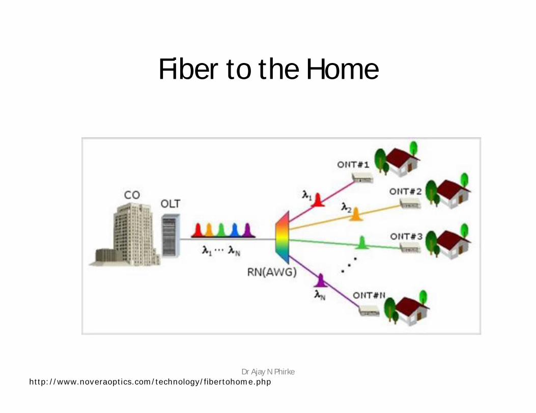
Fiber to the Home
http://www.noveraoptics.com/technology/fibertohome.phpDr Ajay N Phirke
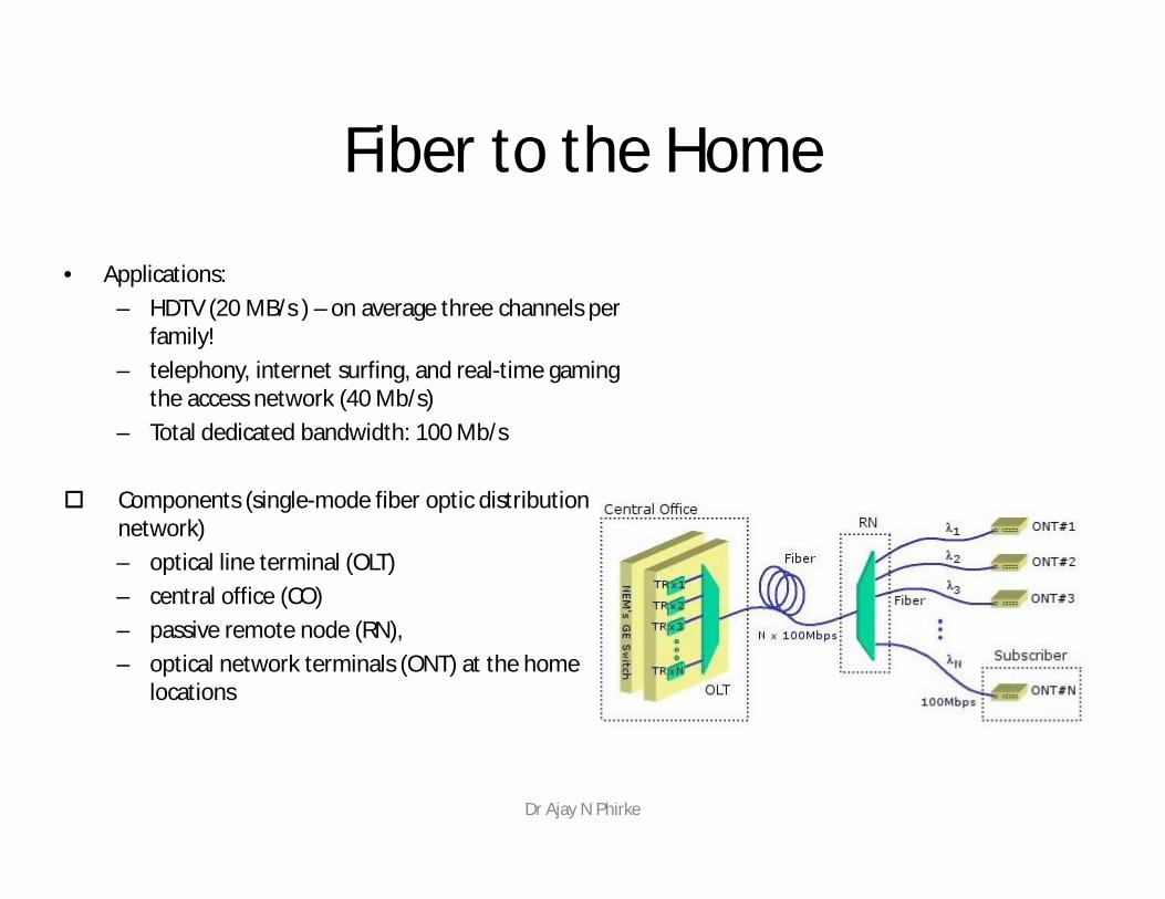
Fiber to the Home
• Applications: – HDTV (20 MB/s ) – on average three channels per
family! – telephony, internet surfing, and real-time gaming
the access network (40 Mb/s)– Total dedicated bandwidth: 100 Mb/s
Components (single-mode fiber optic distribution network)– optical line terminal (OLT)– central office (CO)– passive remote node (RN), – optical network terminals (ONT) at the home
locations
Dr Ajay N Phirke
Dr Ajay N Phirke
Dispersion• Dispersion in fiber optics results from the fact that in
multimode propagation, the signal travels faster in some modes than it would in others
• Single-mode fibers are relatively free from dispersion except for intramodal dispersion
• Graded-index fibers reduce dispersion by taking advantage of higher-order modes
• One form of intramodal dispersion is called material dispersion because it depends upon the material of the core
• Another form of dispersion is called waveguide dispersion• Dispersion increases with the bandwidth of the light source
Dr Ajay N Phirke
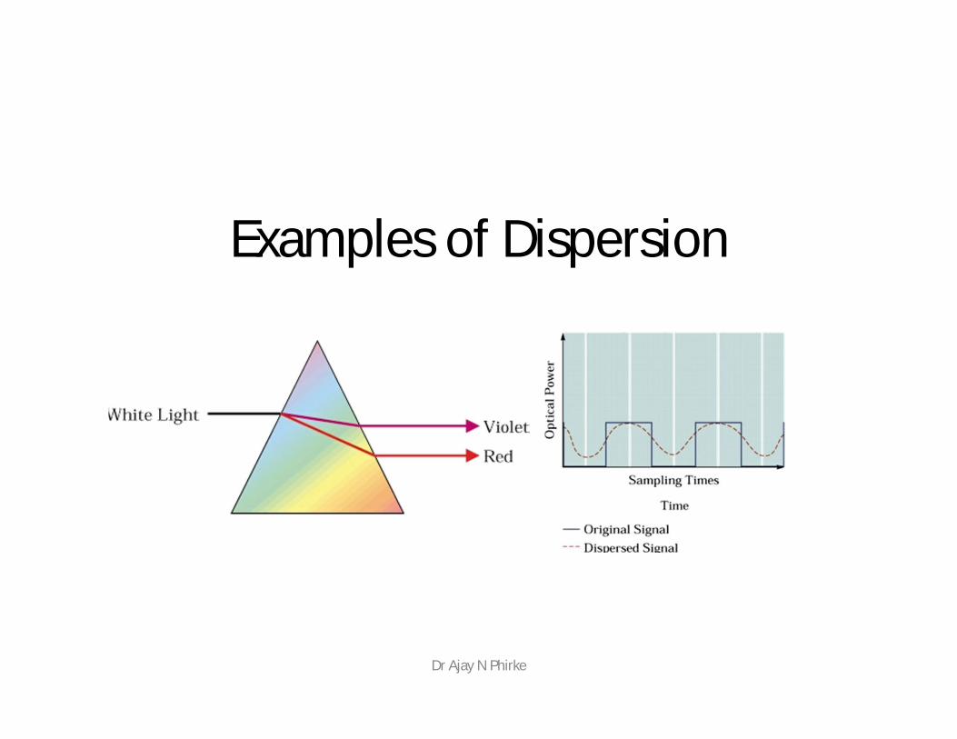
Examples of Dispersion
Dr Ajay N Phirke
Losses• Losses in optical fiber result from attenuation in the
material itself and from scattering, which causes some light to strike the cladding at less than the critical angle
• Bending the optical fiber too sharply can also cause losses by causing some of the light to meet the cladding at less than the critical angle
• Losses vary greatly depending upon the type of fiber– Plastic fiber may have losses of several hundred dB
per kilometer– Graded-index multimode glass fiber has a loss of
about 2–4 dB per kilometer
– Single-mode fiber has a loss of 0.4 dB/km or lessDr Ajay N Phirke
Dr Ajay N Phirke
Dr Ajay N Phirke
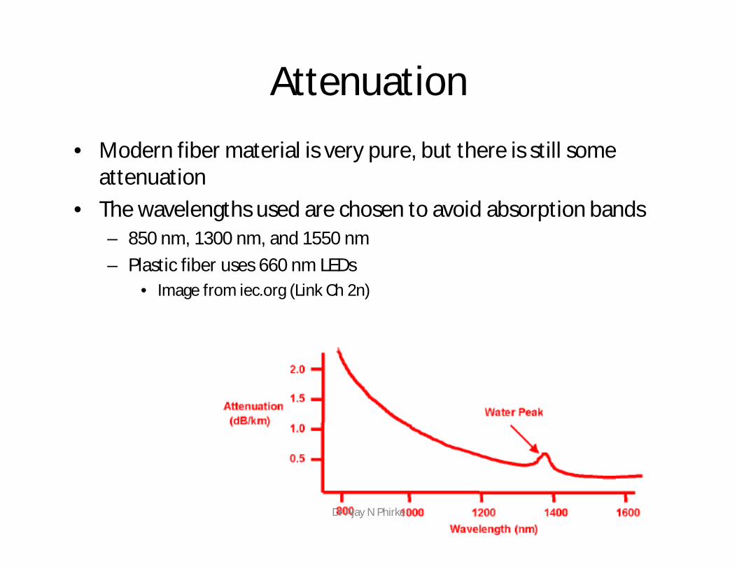
Attenuation• Modern fiber material is very pure, but there is still some
attenuation• The wavelengths used are chosen to avoid absorption bands
– 850 nm, 1300 nm, and 1550 nm– Plastic fiber uses 660 nm LEDs
• Image from iec.org (Link Ch 2n)
Dr Ajay N Phirke
• Fiber has these advantages compared with metal wires– Bandwidth – more data per second– Longer distance– Faster– Special applications like medical imaging and
quantum key distribution are only possible with fiber because they use light directly
Dr Ajay N Phirke
Dr Ajay N Phirke
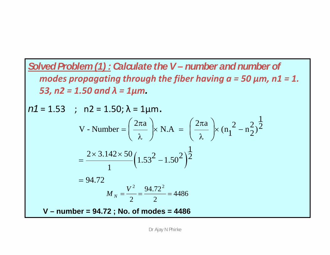
Solved Problem (1) : Calculate the V – number and number of modes propagating through the fiber having a = 50 μm, n1 = 1. 53, n2 = 1.50 and λ = 1μm.
n1 = 1.53 ; n2 = 1.50; λ = 1μm.
12 a 2 a 2 2 2V - Number N.A (n n )1 2
12 3.142 50 2 2 21.53 1.501
94.72
4486272.94
2
22
VM N
V – number = 94.72 ; No. of modes = 4486
Dr Ajay N Phirke

Dr Ajay N Phirke


![Fibre Optics[1]](https://img.pdfslide.us/doc/110x75/577d360a1a28ab3a6b92010d/fibre-optics1.jpg)