Embed Size (px)
Citation preview

Experimental study of Biodiesel
combustion characteristicsBy: Eng. Marwan A. Khalil "El Swaisy"
Under supervision of:
Prof. Dr. T. M. Farag
Dr. A. A. Hanafy
Dr. M. N Anany
1
Arab Academy for Science, Technology, and
Maritime transportDepartment of Mechanical Engineering

Contents1. Introduction
2. Motivation and objectives of study
3. Experimental test rig
4. Experimental procedure
5. Results
6. Conclusions
7. Recommendations
2

Introduction
Background
• Combustion the process
• Importance of combustion
3

Introduction
Combustion Modes
• Combustion is either intermittent as in ICE's or
Continuous like in gas turbines and burners
4

IntroductionContinuous combustion
Continuous combustion features two main types of flames:
1. Premixed flames 2. Diffusion flames
5
Reactants are mixed before entering reaction zone fuel diffuses into the combustion zone
Introduction
• Diffusion flames are the focus of this study due to its
industrial importance
6

Introduction
• Diffusion flames operate optimally when burning
with high air fuel ratios for the following reasons:
1. Ensure a complete combustion process.
2. Reduced environmental impact due to the lower
thermal NOx emitted.
• High air fuel ratios can result in flame instabilities
and blow off.
7

Introduction Flame stabilization
Bluff bodies Swirlers
8
Two common methods used for flame stabilization

Introduction
Fuels for combustion
Fossil Fuel Biofuels

Introduction Fossil fuel dilemma
• Global warming
• Health concerns due to pollutants
• Limited reserves
(Natural gas and liquid petroleum fuels together will last no longer
than 64 years.)
10

Introduction
• Middle East dependency on liquid fuels
Curtsey of BBC news

Biodiesel
• Rudolf diesel
• Trans-esterification
• 1973 oil embargo
12
Introduction

Why biodiesel ?
• Renewable
• Environmental friendly
• Liquid
13
Introduction

Biodiesel blends
Researches concerned with neat Biodiesel have reported major
differences in performance Which, require engine modifications.
Volumetric blends with diesel fuel were suggested to introduce
Biodiesel as commercially ready alternative
14
Introduction

Previous studies with regards to biodiesel
• Biodiesel blends with diesel are now available in gas
stations around the world mainly for use with diesel
engines
15
Introduction

Biodiesel blends in CI engines
• Comparable thermal efficiency in CI engines
• Very good lubricating effect
• CO2 neutral
• Lower SOx
• Higher specific fuel consumption
• Slightly higher NOx
16
In comparison with
commercial Diesel fuel
Introduction

Biodiesel in Continuous Combustion applications
• Lower atomization quality
• Reaction zone of less luminosity
• Palm methyl esters were reported to produce lower soot and NOx
per unit energy compared to Diesel and Jet A1.
• Comparable visual flame length.
17
In comparison with
commercial Diesel fuel
Introduction

1. Introduction
2. Motivation and objectives of study
3. Experimental test rig
4. Experimental procedure
5. Results
6. Conclusions
7. Recommendations
18
You are at slide
16/63

Motivation and objectives of
study
• Contribute towards environment
• Production of Biodiesel in AASTMT labs from waste
vegetable oils
• Testing of the Biodiesel product
19

Objectives of study
• provide a comparative evaluation of the continuous
combustion of Biodiesel blends B20 and B50
against that of Diesel under different operating
conditions. The experimental work divides into two
section:
1. Cold test "Investigating atomization quality"
2. Combustion section "Investigating Flame
characteristics"
20

Evaluate the atomization quality of:
B20, B50, and commercial Diesel
With reference to the spray cone angle
21
Cold test section
Image courtesy of Hago nozzles
Objectives of study

Combustion section investigates:
Flame structure, visual flame length, and mean combustion temperature.
Of
B20, B50, and commercial Diesel
Operating on
A/F= 20 and A/F= 30
Stabilized by swirlers of swirl numbers:
S= 0.5, S=0.87, and S= 1.5
22
Image courtesy of Babcock and Wilcox
Objectives of study

1. Introduction
2. Motivation and Objectives of study
3. Experimental test rig
4. Experimental procedure
5. Results
6. Conclusions
7. Recommendations
23
You are at slide
21/63

24
1- Air blower. 2- Control valve. 3- Air duct. 4- U-tube Manometer. 5- Orifice disc. 6- Fuel tank. 7- Tank valve. 8- Oil filter. 9-
Gear pump. 10- Fuel line. 11- Pressure gauge. 12- Burner body. 13- Cooling water inlet. 14- Cooling jacket 15- Flame
pipe 16- Measurement taping 17- Cooling water outlet 18- Combustor body
Experimental test rigWater-cooled swirl stabilized combustor
1 2 3
4 5
6
7
8
9
10
12
13
14
18
16
15
17
11

Experimental test rig
A
A
1
2
3
4
1-Swirler. 2- Pressure swirl atomizer. 3- Atomizer holder 4- fuel line
Burner assembly

Design considerations
1. Thermal output ranging between 5 to 10 kW.
2. Aspect ratio L/D = 5.
3. Swirlers were designed according to Beer and Chigier swirl no.
Equation
26
Where Ri is the inner swirler diameter, Ro is the outer swirler diameter, and
Alpha is the vane angle.
Experimental test rig

Experimental test rig
• This design facilitates:
1. Measurements and control of air/fuel mass flow rates.
2. Axial and Radial temperature measurements.
3. Axial and Radial species concentration measurements.
4. Operation with variable swirl numbers.
27

28
Pictures through out the fabrication processes
Experimental test rig

29
Experimental test rig

30
Experimental test rig

31
Experimental test rig

32
Experimental test rig

33
Experimental test rig

1. Introduction
2. Motivation and objectives of study
3. Experimental test rig
4. Experimental procedure
5. Results
6. Conclusions
7. Recommendations
34
You are at slide
31/63
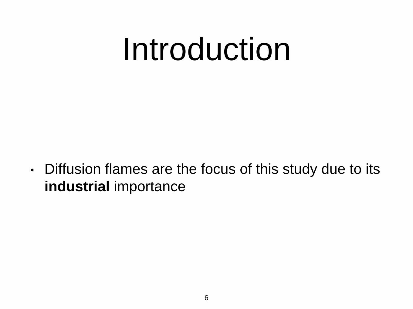
Experimental procedureCalibrations
Air calibrations were done by the means of a mini-vane anemometer,
orifice disc, and a U-tube manometer.
35
Air mass flow rate Vs. dH

Experimental procedureCalibrations
Fuel flow rate was calibrated against injection pressure.
36
Fuel mass flow rate Vs. Injection pressure

Cold test "Spray cone angles"
Pictures of each fuel blend spray were taken for pressure range 1-4bar. Cone angles were
measured of the pictures
37
Injection pressure
(bar) / Fuel typeDiesel B20 B50
1
2
3
4
Experimental procedure

Combustion section:
Flame structure, visual flame length, and mean combustion
temperature.
Through axial and radial temperature measurements
38
Experimental procedure

39
A/F=20 A/F=30
Swirl number /
Fuel typeDiesel B20 B50 Diesel B20 B50
S= 0.5
S= 0.87
S= 1.5
Each of the investigated combustion parameters will have 18 values resulting from 18
experiments structured like the following table
Experimental procedure

1. Introduction
2. Motivation and objective of study
3. Experimental test rig
4. Experimental procedure
5. Results
6. Conclusions
7. Recommendations
40
You are at slide
37/63

1- Spray cone angles
Spray cone angles are direct indication for atomization quality. The wider the
angle the better the atomization.
42
Results

43
Spray Configuration
Results

44
Spray cone angles
Results
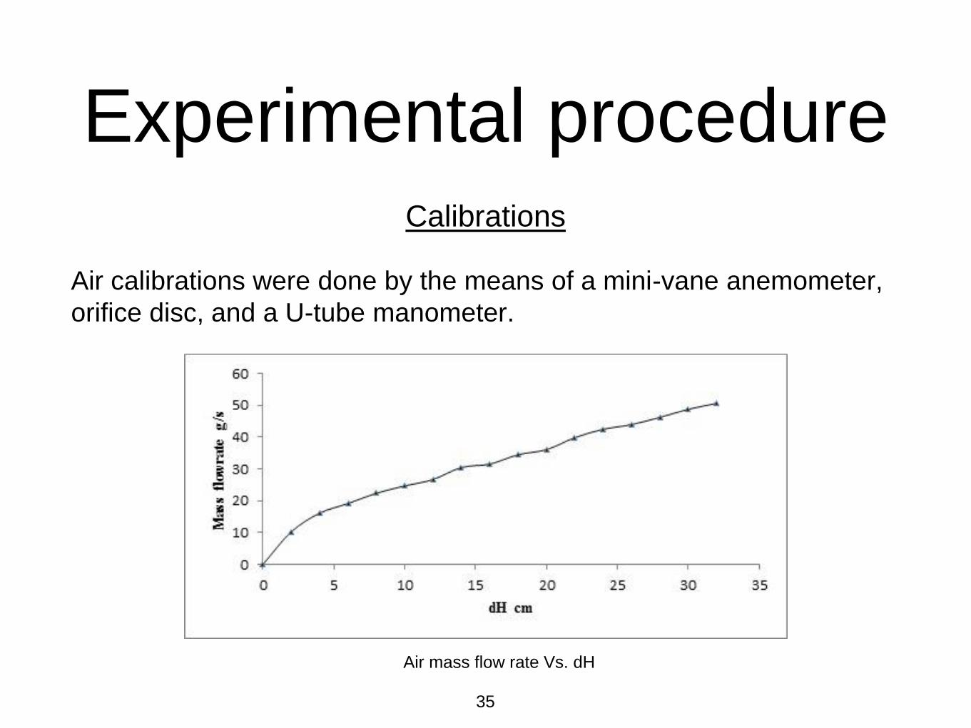
2- Flame structure
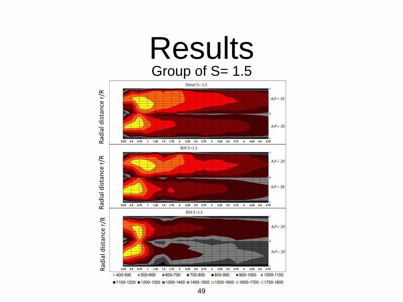
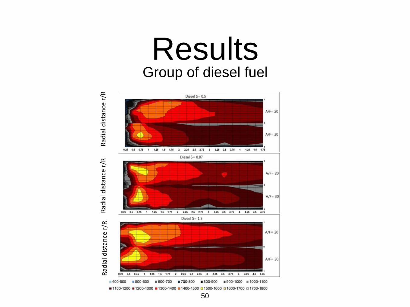
• In this experimental work flame structure is expressed in the form of temperature maps.
• The temperature maps were drawn upon measurements at 11 radial positions starting at combustor wall
ending at combustor center with an incremental step of 10mm. Radial measurements were repeated for 19
axial positions with a center to center distance of 50 mm to form a matrix of 11x19 measurements.
• Assuming Axis-symmetric process.
• Axial positions on the temperature maps are expressed with a dimensionless value x/D, where x is the axial
position and D is the combustor diameter.
• Radial positions on the temperature maps are expressed with a dimensionless value r/R where r is the radial
position and R is the combustor radius
45
Results

• Temperature maps provide crucial information for
designers about:
1. High temperature regions locations.
2. Show the effect of fuel type, swirl number, and air
fuel ratio on radial and axial temperature distributions.
46
Results

47
Group of S= 0.5
Results
Rad
ial d
ista
nce
r/R
Rad
ial d
ista
nce
r/R
Rad
ial d
ista
nce
r/R

48
Group of S= 0.87
Results
Rad
ial d
ista
nce
r/R
Rad
ial d
ista
nce
r/R
Rad
ial d
ista
nce
r/R
49
Group of S= 1.5
Results
Rad
ial d
ista
nce
r/R
Rad
ial d
ista
nce
r/R
Rad
ial d
ista
nce
r/R
50
Group of diesel fuel
Results
Rad
ial d
ista
nce
r/R
Rad
ial d
ista
nce
r/R
Rad
ial d
ista
nce
r/R

51
Group of B20 fuelResults
Rad
ial d
ista
nce
r/R
Rad
ial d
ista
nce
r/R
Rad
ial d
ista
nce
r/R

52
Group of B50 fuel
Results
Rad
ial d
ista
nce
r/R
Rad
ial d
ista
nce
r/R
Rad
ial d
ista
nce
r/R

3- Mean Combustion Temperature MCT
Mean Combustion Temperature MCT is the mean value of all temperature measurements
inside the combustor.
MCT is an indication for mixing and diffusion rates within the same fuel type under different
swirl numbers and air fuel ratios.
MCT is indicative to the extracted thermal energy
53
Results

54
MCT at A/F= 20 MCT at A/F= 30
Results
Showing the effect of fuel type, A/F ratio and Swirl no. On MCT
1060
1080
1100
1120
1140
1160
1180
1200
1220
1240
0.5 0.6 0.7 0.8 0.9 1 1.1 1.2 1.3 1.4 1.5 1.6M
ean
Co
mb
ust
ion
Tem
per
atu
re i
n K
elv
inSwirl no.
Diesel
B20
B50
1140
1160
1180
1200
1220
1240
1260
1280
0.5 0.6 0.7 0.8 0.9 1 1.1 1.2 1.3 1.4 1.5 1.6
Mea
n C
om
bu
stio
n T
emp
era
ture
in
Kel
vin
Swirl no.
Diesel
B20
B50

4- Visual flame length
Records of visual visual flame length have been recorded for each
run in terms of dimensionless ratio x/D.
Flame length is a decisive design parameter for continuos
combustion application.
55
Results

56
Dimensionless visual flame length at A/F= 20 Dimensionless visual flame length at A/F= 30
Results
0
0.25
0.5
0.75
1
1.25
1.5
1.75
0.5 0.6 0.7 0.8 0.9 1 1.1 1.2 1.3 1.4 1.5 1.6
Fla
me
len
gth
x/D
Swirl number
Diesel
B20
B50
0
0.25
0.5
0.75
1
0.5 0.6 0.7 0.8 0.9 1 1.1 1.2 1.3 1.4 1.5 1.6
Fla
m len
gth
x/D
Swirl no.
Diesel
B20
B50

1. Introduction
2. Objectives of study
3. Experimental test rig
4. Experimental procedure
5. Results
6. Conclusions
7. Recommendations
57
You are at slide
55/63
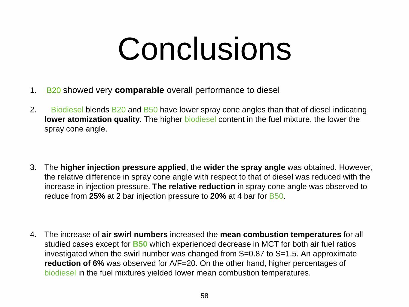
Conclusions1. B20 showed very comparable overall performance to diesel
2. Biodiesel blends B20 and B50 have lower spray cone angles than that of diesel indicating
lower atomization quality. The higher biodiesel content in the fuel mixture, the lower the
spray cone angle.
3. The higher injection pressure applied, the wider the spray angle was obtained. However,
the relative difference in spray cone angle with respect to that of diesel was reduced with the
increase in injection pressure. The relative reduction in spray cone angle was observed to
reduce from 25% at 2 bar injection pressure to 20% at 4 bar for B50.
4. The increase of air swirl numbers increased the mean combustion temperatures for all
studied cases except for B50 which experienced decrease in MCT for both air fuel ratios
investigated when the swirl number was changed from S=0.87 to S=1.5. An approximate
reduction of 6% was observed for A/F=20. On the other hand, higher percentages of
biodiesel in the fuel mixtures yielded lower mean combustion temperatures.
58

4- The increase of either the air swirl number or the air fuel ratio decreases the visual flame
length. At A/F=30 the visual flame length was observed to be independent of the biodiesel content
in the fuel mixture.
5- The increase of air swirl number shifts the high temperature regions in the flame upstream.
However, the biodiesel content played insignificant role on shifting the location of the high
temperature regions. A similar trend was also observed when increasing the air fuel ratio from
A/F=20 to A/F=30.
6- The air fuel ratio reduces the overall mean combustion temperature. Moreover, the increase
in air fuel ratio affects the mean combustion temperature of biodiesel with higher rates than that of
diesel.
59
Conclusions

1. Introduction
2. Objectives of study
3. Experimental test rig
4. Experimental procedure
5. Results
6. Conclusions
7. Recommendations
60
You are at slide
58/61

Recommendations
• Study the emissions of biodiesel blends per unit
energy
• Study the effect of nozzle diameter on biodiesel
blends atomization and combustion
• Study the effect of preheating on biodiesel blends
atomization and combustion
• Study the combustion of biodiesel blends higher than 20
using twin jet atomizer
61

1. Introduction
2. Objectives of study
3. Experimental test rig
4. Experimental procedure
5. Results
6. Conclusions
7. Recommendations
62
Done

Any questions?
Thank you.
63