Embed Size (px)
Citation preview
WELDING RESEARCH
-s279WELDING JOURNAL
ABSTRACT. Martensite start and finishtemperatures are very important in struc-tural steel welding because they controlthe residual stresses in a weld. Tensileresidual stresses amplify the effect of ap-plied tensile stress. On the other hand,compressive residual stresses are alge-braically added to the applied tensilestresses to result in a lower net stress levelexperienced by a weld, thus inhibitingcrack initiation and increasing the fatiguelife of the welded component.
The residual stress state, i.e., whethercompressive or tensile, and its magnitudewill depend on the expansion that accom-panies the austenite-to-martensite trans-formation and the thermal shrinkage dueto cooling. High martensite start temper-ature and low martensite finish tempera-ture will both minimize the effect of trans-formation-induced compressive stressgeneration. To obtain a full martensiticstructure in a weld metal within an optimalrange of temperatures will depend mainlyon the filler metal composition. A newtype of welding wire capable of inducing alocal compressive residual stress state bymeans of controlled martensitic transfor-mation at relatively low temperatures hasbeen studied.
In this study, several low-transforma-tion-temperature welding (LTTW) wireshave been developed and investigated todetermine the martensite start and finishtemperatures of the welds. Also studiedwas the effect of the martensite start andfinish temperatures on microstructuraldevelopment and hardness in single- andmulti-pass weldments.
Introduction
It is well known that high tensile resid-ual stresses near a weld decrease the fa-
tigue performance of the weld becausethese initial stresses, when superimposedon the applied stresses, elevate the overallmean stress (Refs. 1–4). Several proce-dures have been developed to relieve thetensile residual stresses in welded joints.Postweld heat treatment (PWHT) andshot peening are two common methodsused to improve fatigue properties (Ref.3). Another way to reduce or eliminate un-desirable residual stresses in welded partsis to modify the welding process itself. Forexample, low heat input and small weldpool are known to reduce residual stress.Physical and mechanical properties suchas heat capacity, density, thermal expan-sion coefficient, and strength of the basemetal and filler metal contribute to themagnitude of the residual stresses gener-ated in a weld (Refs. 4–6).
It has long been recognized that phasetransformations in steels can radically af-fect the development of residual stresses.For example, Jones and Alberry (Ref. 7)showed how transformation temperaturesinfluence the evolution of stress as a con-strained sample cools from the austenitestate. It is significant that their experi-ments showed that the residual stress atambient temperature is smaller when thetransformation temperature is reduced.
Ohta et al. (Ref. 8) designed a weldingalloy containing 10% Cr and 10% Ni, withan exceptionally low austenite-to-marten-site transformation temperature, TMs. In
this alloy, martensitic transformation in anunconstrained specimen starts at about180°C and ends right at ambient tempera-ture. By contrast, normal steel welding al-loys have transformation temperaturesaround 400°–500°C. As illustrated in Fig.1A, the net strain on cooling betweenTMs and ambient temperature is contrac-tion in the case of the conventional alloy,whereas there is a net expansion for thenew welding wire. As such, local tensileresidual stress results in the conventionalwire and compressive residual stress forthe low-Ms alloy at ambient temperature— Fig. 1B.
When fatigue tests were conducted onwelded sections, the structures joinedusing the low-Ms alloy weld metal exhib-ited much higher fatigue strength (Ref. 8).This improvement of approximately 20%is attributed to the compressive residualstress, which reduces the effective stressrange that the structure experiences dur-ing fatigue testing (Ref. 8). The achieve-ment is based entirely on the fact that thereduction of the transformation tempera-ture allows the expansion originated frommartensite transformation to compensatefor the accumulated thermal contractionstrains. The improved results and the sub-stantial benefits are expected to bring rad-ical changes in fatigue design philosophiesfor structural components. This effect hasrecently been confirmed by Eckerlid et al.(Ref. 9), Martinez Diez (Refs. 10, 11), andDarcis et al. (Ref. 24).
Low-Transformation-Temperature Welding (LTTW)Wires
Martensitic Transformation Approach
Martensitic Transformation — Volume Changeand Residual Stress
The principal decomposition productsof austenite during cooling are precipi-tated phases that include carbides and ni-trides, or the polymorphic phases of al-
Effect of Martensite Start and FinishTemperature on Residual Stress
Development in Structural Steel Welds
The experimental electrodes with lower Cr-Ni contents were found capable ofpromoting compressive residual stresses in welds
BY M. C. PAYARES-ASPRINO, H. KATSUMOTO, AND S. LIU
M. C. PAYARES-ASPRINO is with UniversidadSimón Bolivar, Caracas, Venezuela. H. KAT-SUMOTO is with Sumitomo Metal Industries,Ltd., Kashima-City, Ibaraki, Japan. S. LIU is withColorado School of Mines, Golden, Colo.
KEYWORDS
Martensitic TransformationMartensite Start TemperatureLow Transformation Temperature
Welding ElectrodesLTTW ElectrodesWeld Metal Phase
TransformationsCompressive Residual StressDilatometric MeasurementsConsumable Development
Payares-Asprino Supp Nov 08 corr:Layout 1 10/9/08 10:49 AM Page 279
WELDING RESEARCH
NOVEMBER 2008, VOL. 87-s280
loyed iron, which includes the low-temperature ferrite (α) and the diffusion-less transformation products, BCT α-martensite, and HCP ε-martensite (Ref.12). The BCT martensite phase can bethought of as a variant of the thermody-namically favored α-ferrite, which wouldhave formed from the austenite uponcooling were it not for the severe limita-tion of the diffusional processes due to fastcooling (Ref. 13). In the absence of ferriteformation by nucleation and growth,
austenite undergoes the much more dy-namic martensite transformation, involv-ing short-range atomic rearrangementsover broad interfaces at high velocity. Thediffusionless shear-type martensitic trans-formation requires considerably greaterdriving force than the diffusion-controlledgrowth of ferrite in austenite, due to me-chanical shearing of the austenite lattice.Consequently, martensitic transformationusually requires a considerably greater un-dercooling below the equilibrium temper-
ature, T0, at which the parent and trans-formed phases are in thermodynamicequilibrium. The relative stability of theaustenite phase is very important in orderto induce martensitic transformation at adesired temperature or stress level. Thestrain due to phase transformation canalter the state of residual stress or strain.It is well known that the martensitic trans-formation of the carburized surface of asteel component puts the surface undercompression as a result of the expansion atthe surface due to the formation of thelower-density martensite from austenite.
Martensitic Transformation Temperature
Martensite transformation begins atmartensite start temperature, TMs, (Fig.1), which can vary over a wide tempera-ture range, from as high as 500°C to wellbelow room temperature, depending onthe concentration of γ-stabilizing alloyingelements in the steel. Once TMs is reached,martensite begins to form with furthertransformation taking place during cool-ing until reaching the martensite finishtemperature, TMf — Fig. 1. At this tem-perature, all the austenite should havetransformed to martensite, but frequentlyin practice, a small portion of the austen-ite remains untransformed even at lowtemperatures. Large volume fractions ofaustenite can be retained in some highlyalloyed steels, where the TMf temperatureis well below room temperature.
To achieve martensitic transformation,it is usually necessary for the steel to becooled rapidly, fast enough to suppress thehigher temperature, diffusion-controlled
Fig. 1 — Comparison between the designed low-TMs wire (10% Cr-10% Ni) and conventional steel wire. A — Transformation of weld metal during uncon-strained cooling; B — development of stress during constrained cooling (Ref. 8).
A B
Table 1 — Compositions of the Welds (in wt-%) Produced Using the CSM ExperimentalMetal-Cored Wires
Wires C Mn Cr Ni P Mo Si S Ti
Al 0.04 0.89 10.00 0.30 <0.01 0.04 0.20 <0.01 <0.01A6 0.08 0.89 14.70 0.27 <0.01 0.04 0.19 <0.01 <0.01B5 0.04 0.86 13.00 1.70 <0.01 0.04 0.16 <0.01 <0.01C5 0.05 0.41 3.00 13.2 <0.01 0.35 0.22 <0.01 <0.01
ER70S-3 0.09 1.02 0.05 0.03 <0.01 <0.01 0.41 <0.01 <0.01
Table 2 — Transformation Temperatures Measured Using Dilatometry
Wire Ac1 Ac3 Ar3 (TMs, TFs)(a) Ar1 (TMf,TFf)(a) εf(%)(b)
A1 800 850 390 284 0.244A6 790 815 360 190 0.081B5 740 780 300 225 0.416C5 635 720 270 120 0.570
ER70S-3 820 860 645 580 –0.570
(a) TMs and TMf are for A1, A6, B5, and C5.TFs and TFf are for ER70S-3
(b) The final strain (εf) is defined as the amount of expansion from the TMs of TFs temperature to the roomtemperature. Positive means an expansive strain exists at room temperature, negative means a contractive strainexists.
Elo
ng
atio
n
Str
ess
σ (M
Pa)
Payares-Asprino Supp Nov 08 corr:Layout 1 10/8/08 4:46 PM Page 280
WELDING RESEARCH
-s281WELDING JOURNAL
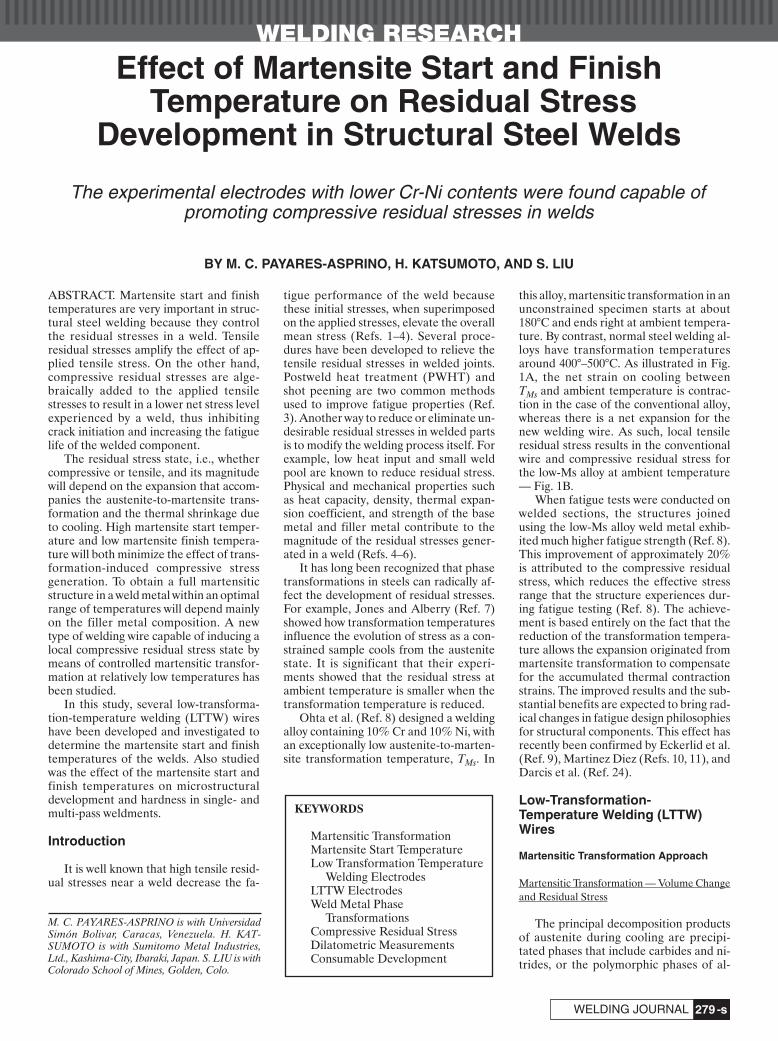
Fig. 2 — Compositions of the welds plotted on the Schaeffler diagram. Fig. 3 — Cylindrical specimens according to theGleeble standard specimen were extracted fromthe welds. (All dimensions are given in mm.)
ferrite and pearlite reactions, as well asother intermediate reactions such as theformation of bainite.
According to transformation charac-teristics, alloys can be divided into twoclasses with respect to martensite forma-tion: 1) those that affect the equilibriumaustenite decomposition temperature(T0), and 2) those that affect the necessaryundercooling below T0, i.e., ΔTm = T0 –TMs (Ref. 14). T0 is influenced by thechemical composition of the alloy, degreeof order, hydrostatic stress (Ref. 15) (clas-sical thermodynamic factors), and ΔTm,which is influenced by the difficulty ofmartensite nucleation and growth withinthe austenite matrix (kinetic, activationfactor). The factors that affect the ΔTm in-clude external shear stresses and any otherproducts that may affect the resistance ofthe base austenite lattice to mechanicalshear during martensite transformation,e.g., hardening mechanism, point defects,dislocations, and precipitates.
Martensite Formation — Influence of AlloyingElements
The effect of alloying elements on theTMs temperature has been studied by
many researchers. Izumiyama et al. (Ref.16) showed the effects of individual alloy-ing of 13 elements. Their results showedthat Al, Ti, V, Nb, and Co effectively in-creased the TMs, whereas Si, Cu, Cr, Ni,Mn, and C decreased the TMs tempera-ture. However, Liu (Ref. 17) reported dif-ferent effects for some of the elements. He
showed that all alloying elements men-tioned earlier (Mn, V, Cr, Cu, W, Si), ex-cept Al and Co, decreased the TMs tem-perature. The different observations arenot unexpected since different processingconditions (e.g., austenitizing conditionsand cooling rates), austenite grain size,and impurity content will significantly af-
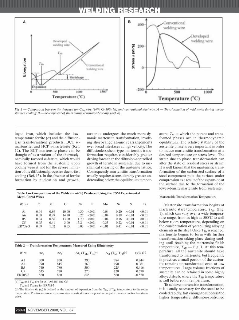
Fig. 4 — Dilatometric curves of the welds made using the experimental wires and commercial wire.
A B C
D E
Payares-Asprino Supp Nov 08 corr:Layout 1 10/8/08 4:48 PM Page 281
WELDING RESEARCH
NOVEMBER 2008, VOL. 87-s282
fect the martensite transformation behav-ior. All these metallurgical factors need tobe carefully considered in order to man-age the martensite transformation behav-ior of an alloy.
This paper describes the developmentand characterization of several LTTWconsumables that contained lower com-bined alloy contents (than the 10% Cr and10% Ni developed by Ohta et al. (Ref. 8))for the management of weld residualstresses and improvement of weld joint fa-tigue properties. Metal cored electrodeswere manufactured and welds prepared.The welds were analyzed for chemicalcomposition and specimens were ex-tracted for dilatometric analysis for TMsdetermination. The welds were also cross-sectioned for metallography and hardnesstesting.
Experimental Procedures
Chemical Composition of the Weld
The CSM-designed filler metal pro-duced ferrite-martensite and ferrite-austenite microstructure. The composi-tion of the welds produced using the fourmetal-cored welding wires are shown inTable 1.
The chromium and the nickel equiva-lents of each of the welds were calculatedand plotted on the Schaeffler diagram asshown in Fig. 2. A1, A6, and B5 are ex-pected to result in a ferrite–martensite mi-crostructure while C5 is expected to bemartensitic with some retained austenite.
For comparison, a commercial solidwire, AWS ER70S-3, was also included inthe research. Two models were used to cal-culate the martensite start temperaturesof these alloys, the Self-Olson Equation(Refs. 18, 19) and the methodology pro-posed by Ghosh and Olson (Refs. 20–22).Scanning electron microscopy (SEM) andenergy-dispersive spectroscopy (EDS)were used to examine the microstructureas well as alloying element segregation inthe welds.
Dilatometric Measurements
Dilatometric specimens were extractedfrom single-pass welds deposited on anA36 grade structural steel using the fourexperimental consumables and the com-mercial ER70S-3 wire. The dilatometricmeasurements were made on a Gleeblethermomechanical simulator (Fig. 3)using 6-mm-diameter and 80-mm-lengthsamples. The small cylinders were heatedat the rate of 10°C/s to 1050°C and held atthat temperature for 3 min, followed byquenching in a helium jet at the coolingrate of 100°C/s.
Table 3 — Experimentally Measured and Calculated Martensite Start Temperatures of WeldMetal
Experimental Self-Olson Equation Ghosh and OlsonWires TMs TMs TMs
(C°) (C°) (C°±400)
A1 416 334 332A6 360 280 325B5 301 260 318C5 279 175 291
ER70S-3 620(a) — —
(a) Ferrite transformation start temperature (TFs).
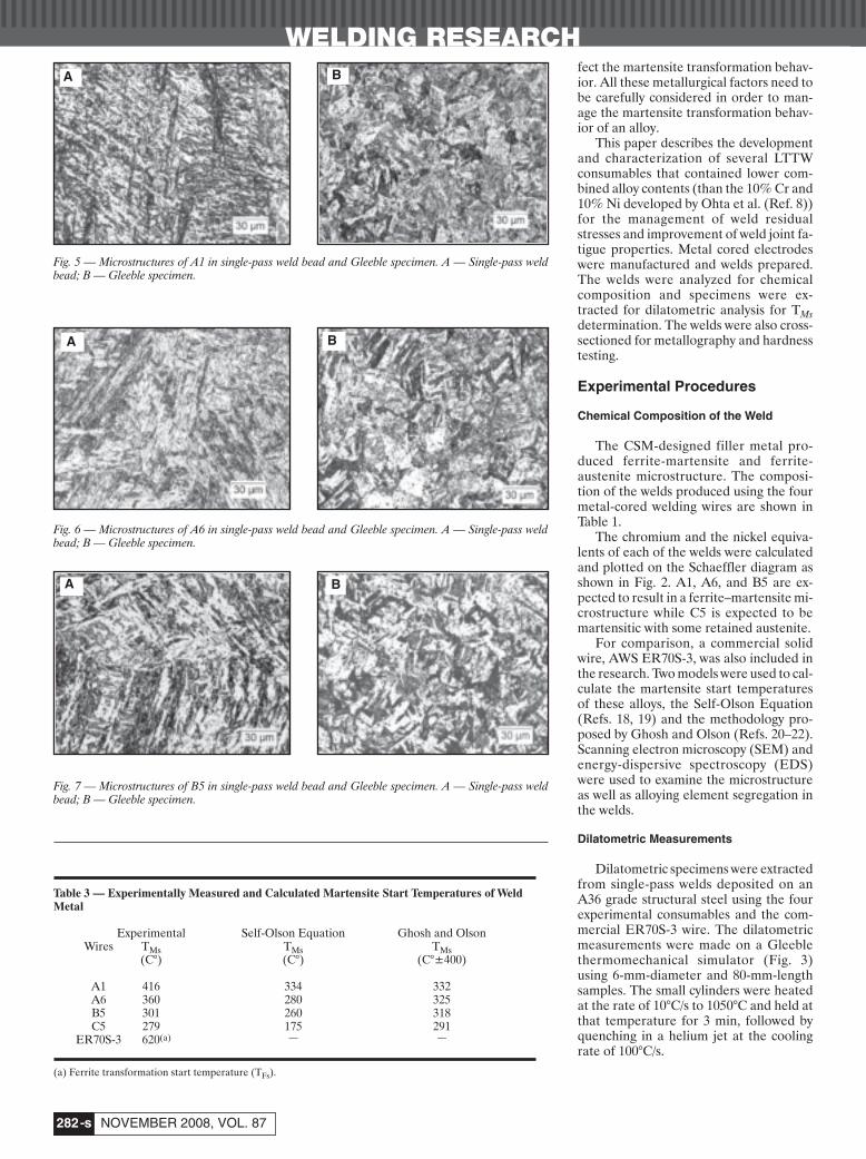
Fig. 5 — Microstructures of A1 in single-pass weld bead and Gleeble specimen. A — Single-pass weldbead; B — Gleeble specimen.
Fig. 6 — Microstructures of A6 in single-pass weld bead and Gleeble specimen. A — Single-pass weldbead; B — Gleeble specimen.
Fig. 7 — Microstructures of B5 in single-pass weld bead and Gleeble specimen. A — Single-pass weldbead; B — Gleeble specimen.
A B
A B
A B
Payares-Asprino Supp Nov 08 corr:Layout 1 10/8/08 4:49 PM Page 282
WELDING RESEARCH
-s283WELDING JOURNAL
Microstructural Development
The specimens were prepared to a mir-ror-finish using standard metallographictechniques and etched with the KallingNo. 2 reagent (1.5 g CuCl2 + 33 mL HCl+ 33 mL ethanol + 33 mL H2O) accord-ing to ASTM E407 and E340 testing tech-niques. Photomicrographs were takenusing a LECO Olympus PMG-3 field mi-croscope, coupled to a PaxCAM camera.Area fractions of martensite and ferritewere measured using the point countingtechnique.
Microhardness Distribution in the Weldments
Microhardness testing was conductedon transverse cross sections taken fromthe welds. Measurements were made on aVickers microhardness scale with a load of300 g. The objective of this study was toevaluate the hardness of single- and multi-pass welds; both as-solidified and re-heated zones were measured. In the caseof multipass welds, measurements weremade in the “No-Reheat” (as-solidified)zone, “Once-Reheated” (reheated weldmetal) zone, and “Twice-Reheated”(overlapping reheated) zones.
Samples for microhardness testingwere first etched to identify the weld fu-sion zone. Hardness measurements weremade across the weld interface at two dif-ferent distances from the surface of thelast bead of the weldments. Indentationswere made at increments of 0.3175 mm in-side the weld metal. However, the incre-ments between successive measurementswere reduced to 0.1588 mm when ap-proaching the reheated zones in order todetect changes in hardness in these areas.
Results and Analysis
Results from the dilatometric analysisand microstructural analysis are pre-sented and discussed in the following.
Dilatometric Analysis
The dilatometric curves and themartensite start temperature data are pre-sented. In addition, the experimentally de-termined values are compared with thepredicted values using the Self-Olsonequations and the Ghosh-Olson method-ology.
Dilatrometric Curves
Figure 4 shows the dilatometric curvesfor the four designed and conventionalwires obtained using the Gleeble thermo-mechanical simulator. Martensitic trans-formation occurred in all four designedwires. The martensite start temperature
and the relative strain (compressive ortensile) are recorded on each of the fig-ures. Data from the C5 sample was se-lected for further description and inter-pretation of the dilatometricmeasurements. At the beginning of thetest, the percent strain was zero. With in-creasing temperature, the sample beganto expand as evidenced by the positivestrain. Ferrite-to-austenite transforma-tion (α → γ) began at approximately 635°Cand ended at around 720°C, representing
a deviation from the equilibrium Ac1 andAc3 temperatures. The negative slopeduring α → γ transformation indicatescontraction because of the denser atomicpacking factor of austenite. After theholding temperature of 1050°C, the sam-ple was allowed to cool down at the rate of100°C/s and contraction was observed. At270°C, the slope began to change again in-dicating that martensite began to form.Up to this point, cooling has amounted toa contraction of about 1.8% (from +1.2 to
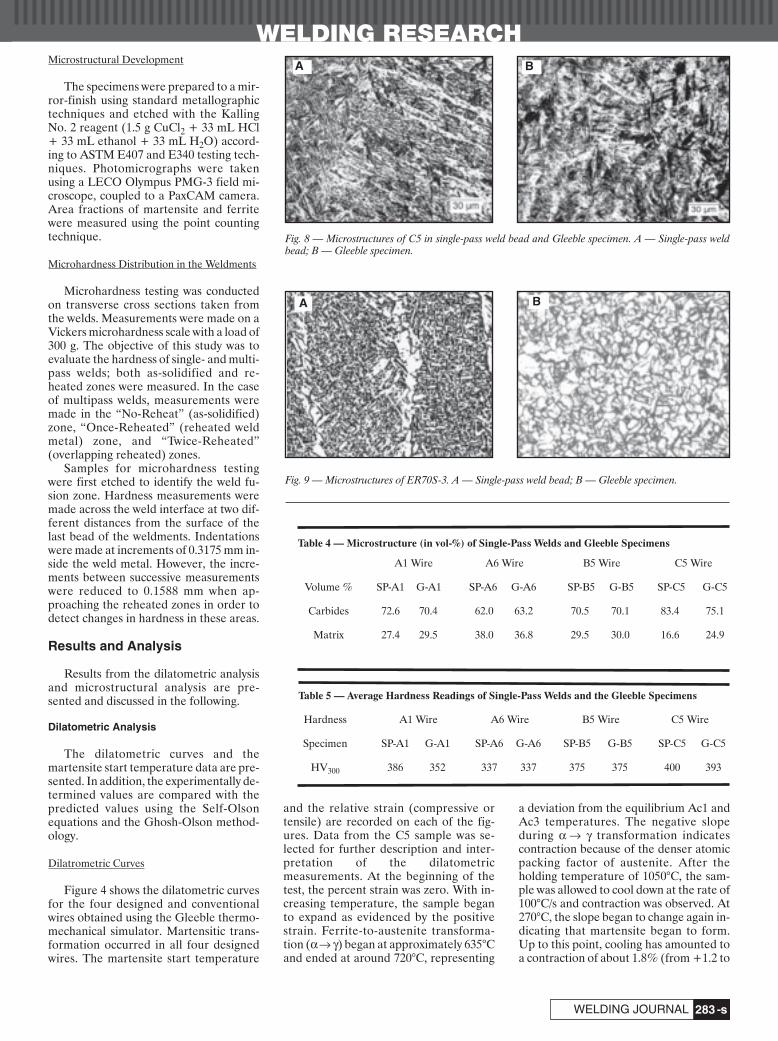
Table 4 — Microstructure (in vol-%) of Single-Pass Welds and Gleeble Specimens
A1 Wire A6 Wire B5 Wire C5 Wire
Volume % SP-A1 G-A1 SP-A6 G-A6 SP-B5 G-B5 SP-C5 G-C5
Carbides 72.6 70.4 62.0 63.2 70.5 70.1 83.4 75.1
Matrix 27.4 29.5 38.0 36.8 29.5 30.0 16.6 24.9
Table 5 — Average Hardness Readings of Single-Pass Welds and the Gleeble Specimens
Hardness A1 Wire A6 Wire B5 Wire C5 Wire
Specimen SP-A1 G-A1 SP-A6 G-A6 SP-B5 G-B5 SP-C5 G-C5
HV300 386 352 337 337 375 375 400 393
Fig. 8 — Microstructures of C5 in single-pass weld bead and Gleeble specimen. A — Single-pass weldbead; B — Gleeble specimen.
Fig. 9 — Microstructures of ER70S-3. A — Single-pass weld bead; B — Gleeble specimen.
A B
A B
Payares-Asprino Supp Nov 08 corr:Layout 1 10/8/08 4:50 PM Page 283
WELDING RESEARCH
NOVEMBER 2008, VOL. 87-s284
–0.6%). Assuming that the welded struc-ture was entirely rigid, the contraction ofaustenite would have resulted in tensileresidual stresses. However, with the for-mation of martensite and its more openbody-centered tetragonal (BCT) crystalstructure, the contraction reversed to ex-pansion. Finally, at room temperature, thestrain reached around zero.
The martensite transformation starttemperature (TMs) is identified as the tem-perature at which the slope changed frompositive to negative during cooling. Simi-larly, the martensite transformation finishtemperature (TMf) can be identified as thetemperature when the negative slopeturned to positive. Even though it is notnecessary for all the austenite to decom-pose into martensite at Mf to control resid-ual stress, the magnitude of the expansionis important since it is responsible for off-setting the residual tensile stress state thatoriginated from thermal contraction.
Sample C5 exhibited the lowest TMstemperature and the largest amount of ex-pansion. The expansive strain also re-mained at room temperature. These re-sults indicate that compressive residualstresses can be induced in the vicinity ofthe weld metal in a welded joint producedusing the C5 welding wire.
Martensite transformation initiated insample A1 at 390°C and the amount of ex-pansion was around 0.5% (from –0.3% to0.2%). Nevertheless, the martensite trans-formation completed at a relatively hightemperature, around 284°C. Thus, a partof the effect of expansion would be offsetby subsequent cooling and contraction ofthermal origin. The overall strain (εf) forsample A1, measured from the onset ofmartensitic transformation to room tem-perature, was only 0.244% as indicated inFig. 4. It is clear by comparing sample C5with A1 that the onset and the end ofmartensite transformation are just as im-portant as the magnitude of the expansionin controlling the final residual stress statein a welded joint. For comparison, the TMs,TMf, and εf of sample A6 are 360°C, 190°C,and 0.244%, respectively. For sample B5,these values are 300°C, 225°C, and0.578%. Lower TMs and TMf, and larger εfwill maximize the compressive residualstress in a welded joint.
On the contrary, a phase transforma-tion was observed to start at 645°C and fin-ished at 580°C during cooling in sampleER70S-3. Microscopic observation con-cluded that ferrite transformation oc-curred instead of martensite transforma-tion. The lower alloying content of thiswelding wire certainly supports this obser-vation. After the transformation, coolinghas amounted to a contraction of 0.57%and then the strain reached around zero atroom temperature. These measurements
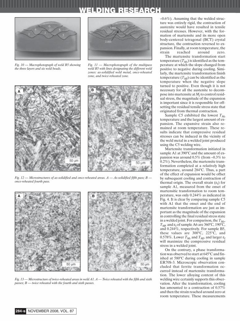
Fig. 10 — Macrophotograph of weld B5 showingthe three layers and six weld beads.
Fig. 11 — Macrophotograph of the multipassweld B5 with lines designating the different weldzones: as-solidified weld metal, once-reheatedzone, and twice-reheated zone.
Fig. 12 — Microstructures of as-solidified and once-reheated areas. A — As-solidified fifth pass; B —once-reheated fourth pass.
Fig. 13 — Microstructure of twice-reheated areas in weld A1. A — Twice reheated with the fifth and sixthpasses; B — twice reheated with the fourth and sixth passes.
A B
A B
Payares-Asprino Supp Nov 08 corr:Layout 1 10/8/08 4:51 PM Page 284
WELDING RESEARCH
-s285WELDING JOURNAL
indicate that tensile residual stresses willresult in the welded joint. The character-istics of the microstructures will be dis-cussed later.
Table 2 shows the summary of thedilatometric analysis.
Comparison between Measured and PredictedMs Temperatures
Experimentally measured martensitetransformation temperatures (TMs) of thedesigned wires are listed in Table 3, whichalso contains the TMs temperatures as es-timated using the Self-Olson equation(Refs. 17, 18) and the Ghosh-Olsonmethodology (Refs. 19–21). The tempera-ture of the conventional wire, ER70S-3,indicates ferrite transformation start tem-
perature (TFs).As can be seen in Table 3, the Ghosh
and Olson methodology appears to betterpredict the TMs temperatures for these ex-perimental alloys. Since the Self-OlsonEquations were derived statistically basedon a number of alloys, this equation is ex-pected to provide more accurate resultsfor alloys whose compositions fall withinthe range of the database.
Weld Microstructure
Comparison of Microstructure between Single-Pass and Gleeble Specimen
Figures 5–8 are micrographs of the sin-gle-pass weld beads and the Gleeble spec-imens from each of the designed wires. All
were martensitic in nature. However, thetwo microstructures, i.e., single-pass weldand Gleeble specimen, are slightly differ-ent because the Gleeble specimens wereextracted from bead-on-bead (BOB)welds, which experienced multiple ther-mal cycles.
Figure 9 shows the microstructures ofthe ER70S-3 single-pass weld bead andthe Gleeble specimen. Ferrite clearly pre-dominated in the microstructure. Morespecifically, acicular ferrite and grainboundary ferrite veining were the twomajor features observed in the single-passweld while 100% polygonal ferrite wasfound in the Gleeble specimen.
The volume percents of the matrix mi-crostructure (white in the figures) and car-bides (black or gray) were determined
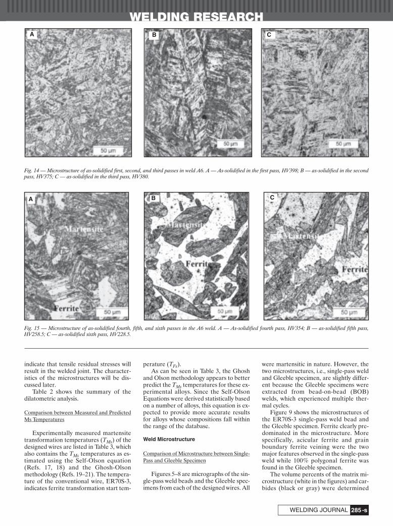
Fig. 14 — Microstructure of as-solidified first, second, and third passes in weld A6. A — As-solidified in the first pass, HV398; B — as-solidified in the secondpass, HV375; C — as-solidified in the third pass, HV380.
Fig. 15 — Microstructure of as-solidified fourth, fifth, and sixth passes in the A6 weld. A — As-solidified fourth pass, HV354; B — as-solidified fifth pass,HV258.5; C — as-solidified sixth pass, HV228.5.
A B C
CBA
Payares-Asprino Supp Nov 08 corr:Layout 1 10/8/08 4:50 PM Page 285
using the point counting technique. Theresults for the single-pass welds and theGleeble specimens are listed in Table 4.
Hardness profiles were measured onthe dilatometric specimens and single-pass weldments. The average hardnessreadings are listed in Table 5. All readingscorresponded to martensitic microstruc-ture. Comparing the hardness test resultsfrom the actual single-pass welds, the val-ues of the Gleeble specimens were lower,again due to the multiple thermal cyclesexperienced.
Microstructure of Multipass WeldSpecimens
Characterization of the weld metal andreheated zone microstructures of thewelds is described in this section. Amacrophotograph of the three layer (six-pass B5) weldment is shown in Fig. 10. Thesolid lines trace the weld interfaces of eachindividual bead, identified by numbers; 1indicates the first bead and 6 indicates thesixth bead. As shown in Fig. 11, the weld-ment was composed of three zones: a) as-solidified zone marked “As-S,” b) once-
reheated zone marked “1-RH,” and c)twice-reheated zone named “2-RH.”
Multipass Weld A1
Figure 12A and B show the as-solidi-fied microstructure in the fifth pass andthe once-reheated microstructure in thefourth pass, respectively. The as-solidifiedweld metal, Fig. 12A, was fully martensiticwith a hardness reading of 383 on theVickers scale. The reheated weld metal inFig. 12B showed martensite and bainite,with an average hardness of HV292, whichis lower than that measured in a fullymartensitic microstructure. Bainiteformed as a result of tempering.
Figure 13A and B show the mi-crostructures of twice-reheated regions.These microstructures are more bainiticas compared to that of the single-reheatedregions. The lower hardness values of 288and 248 confirm the effect of multiplethermal cycles.
Multipass Weld A6
Figure 14A, B, and C show the micro-
graphs of as-solidified first pass, secondpass, and third pass, respectively, all withfully martensitic microstructure. Sincecarbon is low in these welds, the marten-site is lathy in nature.
Different from the first, second, andthird pass, the as-solidified fifth and sixthpasses did not show 100% martensite inthe microstructure. Instead, the marten-site appeared as islands in the ferrite ma-trix as shown in Fig. 15A–C. These mor-phologies are similar to those reported inthe literature, which described the undi-luted microstructure of a weld metal ofType 403 martensitic stainless steel thatcontained 0.11% C, 12.38% Cr, and 0.28%Ni (Ref. 23). The amount of martensite inA6 wire weld was less than that of a type403 stainless steel weld due to the lowercarbon content of A6. The appearance offerrite together with martensite will be ex-plained in the next section on EDS analy-sis results.
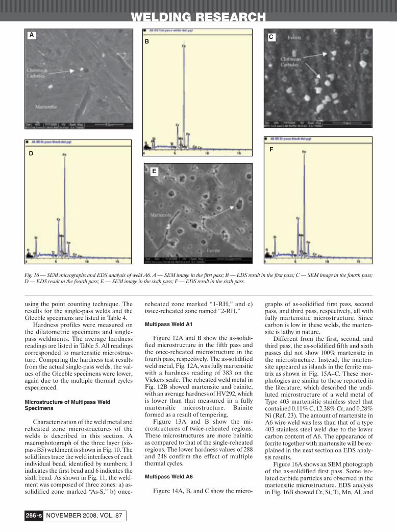
Figure 16A shows an SEM photographof the as-solidified first pass. Some iso-lated carbide particles are observed in themartensitic microstructure. EDS analysisin Fig. 16B showed Cr, Si, Ti, Mn, Al, and
WELDING RESEARCH
NOVEMBER 2008, VOL. 87-s286
Fig. 16 — SEM micrographs and EDS analysis of weld A6. A — SEM image in the first pass; B — EDS result in the first pass; C — SEM image in the fourth pass;D — EDS result in the fourth pass; E — SEM image in the sixth pass; F — EDS result in the sixth pass.
B
DF
A
E
C
Payares-Asprino Supp Nov 08 corr:Layout 1 10/8/08 4:53 PM Page 286
WELDING RESEARCH
-s287WELDING JOURNAL
Fe in the carbides. During welding, thefirst pass is expected to be more affectedby dilution from the base steel. As such,the as-solidified first pass weld metaltransformed into martensite because ofcarbon pickup from the base metal. Onthe contrary, in the later passes, weld met-als contained less carbon and thereforemartensite plus ferrite microstructuresappeared. Figure 16C shows the SEMphotograph of the as-solidified fourthpass, in which the effect of dilution was re-duced. Larger carbide particles can be ob-served in the ferrite microstructure than inthe first pass. The carbides were com-posed of Cr, Ti, Mn, and Fe. As a result ofcarbide precipitation, a carbon-depletedzone is expected to form around the car-bides. The lower carbon content wouldthen result in the formation of ferritearound the carbide particles. The ferritenext to the carbide precipitates in Fig. 16Cconfirms the explanation above.
On the other hand, many oxides com-posed of Si, Cr, Mn, Al, and Fe were ob-served in the as-solidified sixth pass inwhich little dilution of the base steel oc-curred, as shown in Fig. 16E. With thelower carbon in this region, the mi-crostructure became ferrite and marten-site as shown in Fig. 15B. High hardnessvalues (above 300) resulted in these re-gions when the indent was located on themartensite even the regions were re-heated. On the contrary, when the indentwas on the ferrite matrix, the hardness val-ues would be low.
Multipass Weld B5
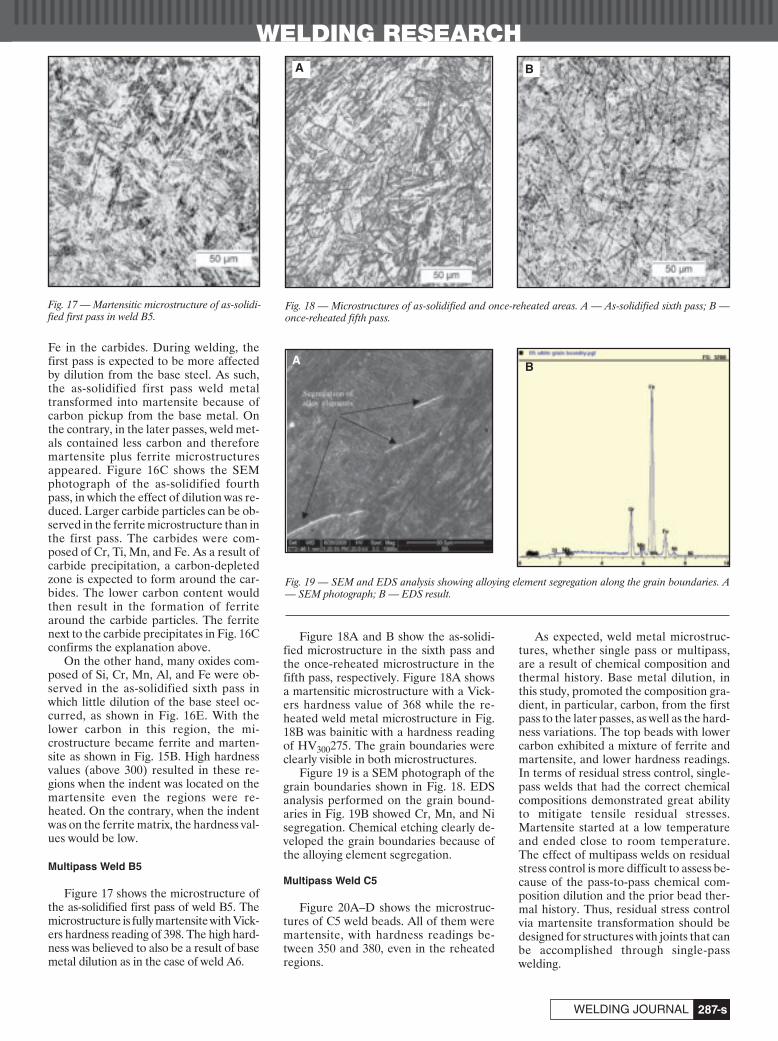
Figure 17 shows the microstructure ofthe as-solidified first pass of weld B5. Themicrostructure is fully martensite with Vick-ers hardness reading of 398. The high hard-ness was believed to also be a result of basemetal dilution as in the case of weld A6.
Figure 18A and B show the as-solidi-fied microstructure in the sixth pass andthe once-reheated microstructure in thefifth pass, respectively. Figure 18A showsa martensitic microstructure with a Vick-ers hardness value of 368 while the re-heated weld metal microstructure in Fig.18B was bainitic with a hardness readingof HV300275. The grain boundaries wereclearly visible in both microstructures.
Figure 19 is a SEM photograph of thegrain boundaries shown in Fig. 18. EDSanalysis performed on the grain bound-aries in Fig. 19B showed Cr, Mn, and Nisegregation. Chemical etching clearly de-veloped the grain boundaries because ofthe alloying element segregation.
Multipass Weld C5
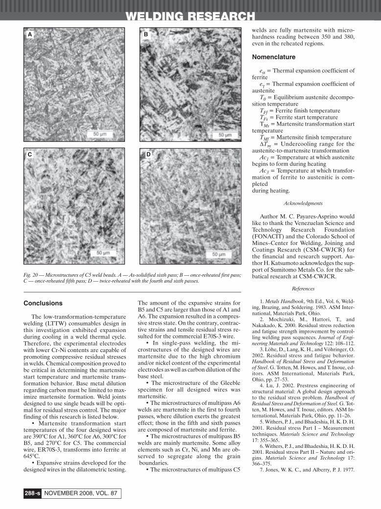
Figure 20A–D shows the microstruc-tures of C5 weld beads. All of them weremartensite, with hardness readings be-tween 350 and 380, even in the reheatedregions.
As expected, weld metal microstruc-tures, whether single pass or multipass,are a result of chemical composition andthermal history. Base metal dilution, inthis study, promoted the composition gra-dient, in particular, carbon, from the firstpass to the later passes, as well as the hard-ness variations. The top beads with lowercarbon exhibited a mixture of ferrite andmartensite, and lower hardness readings.In terms of residual stress control, single-pass welds that had the correct chemicalcompositions demonstrated great abilityto mitigate tensile residual stresses.Martensite started at a low temperatureand ended close to room temperature.The effect of multipass welds on residualstress control is more difficult to assess be-cause of the pass-to-pass chemical com-position dilution and the prior bead ther-mal history. Thus, residual stress controlvia martensite transformation should bedesigned for structures with joints that canbe accomplished through single-passwelding.
Fig. 17 — Martensitic microstructure of as-solidi-fied first pass in weld B5.
Fig. 18 — Microstructures of as-solidified and once-reheated areas. A — As-solidified sixth pass; B —once-reheated fifth pass.
Fig. 19 — SEM and EDS analysis showing alloying element segregation along the grain boundaries. A— SEM photograph; B — EDS result.
A B
A B
Payares-Asprino Supp Nov 08 corr:Layout 1 10/8/08 4:54 PM Page 287
Conclusions
The low-transformation-temperaturewelding (LTTW) consumables design inthis investigation exhibited expansionduring cooling in a weld thermal cycle.Therefore, the experimental electrodeswith lower Cr-Ni contents are capable ofpromoting compressive residual stressesin welds. Chemical composition proved tobe critical in determining the martensitestart temperature and martensite trans-formation behavior. Base metal dilutionregarding carbon must be limited to max-imize martensite formation. Weld jointsdesigned to use single beads will be opti-mal for residual stress control. The majorfinding of this research is listed below.
• Martensite transformation starttemperatures of the four designed wiresare 390°C for A1, 360°C for A6, 300°C forB5, and 270°C for C5. The commercialwire, ER70S-3, transforms into ferrite at645°C.
• Expansive strains developed for thedesigned wires in the dilatometric testing.
The amount of the expansive strains forB5 and C5 are larger than those of A1 andA6. The expansion resulted in a compres-sive stress state. On the contrary, contrac-tive strains and tensile residual stress re-sulted for the commercial E70S-3 wire.
• In single-pass welding, the mi-crostructures of the designed wires aremartensite due to the high chromiumand/or nickel content of the experimentalelectrodes as well as carbon dilution of thebase steel.
• The microstructure of the Gleeblespecimen for all designed wires wasmartensitic.
• The microstructures of multipass A6welds are martensite in the first to fourthpasses, where dilution exerts the greatesteffect; those in the fifth and sixth passesare composed of martensite and ferrite.
• The microstructures of multipass B5welds are mainly martensite. Some alloyelements such as Cr, Ni, and Mn are ob-served to segregate along the grainboundaries.
• The microstructures of multipass C5
welds are fully martensite with micro-hardness reading between 350 and 380,even in the reheated regions.
Nomenclature
eα = Thermal expansion coefficient offerrite
eγ = Thermal expansion coefficient ofaustenite
T0 = Equilibrium austenite decompo-sition temperature
TFf = Ferrite finish temperatureTFs = Ferrite start temperatureTMs = Martensite transformation start
temperature TMf = Martensite finish temperatureΔTm = Undercooling range for the
austenite-to-martensite transformationAc1 = Temperature at which austenite
begins to form during heatingAc3 = Temperature at which transfor-
mation of ferrite to austenitic is com-pleted during heating.
Acknowledgments
Author M. C. Payares-Asprino wouldlike to thank the Venezuelan Science andTechnology Research Foundation(FONACIT) and the Colorado School ofMines–Center for Welding, Joining andCoatings Research (CSM-CWJCR) forthe financial and research support. Au-thor H. Katsumoto acknowledges the sup-port of Sumitomo Metals Co. for the sab-batical research at CSM-CWJCR.
References
1. Metals Handbook, 9th Ed., Vol. 6, Weld-ing, Brazing, and Soldering. 1983. ASM Inter-national, Materials Park, Ohio.
2. Mochizuki, M., Hattori, T., andNakakado, K. 2000. Residual stress reductionand fatigue strength improvement by control-ling welding pass sequences. Journal of Engi-neering Materials and Technology 122: 108–112.
3. Löhe, D., Lang, K. H., and Vöhringer, O.2002. Residual stress and fatigue behavior.Handbook of Residual Stress and Deformationof Steel. G. Totten, M. Howes, and T. Inoue, ed-itors. ASM International, Materials Park,Ohio, pp. 27–53.
4. Lu, J. 2002. Prestress engineering ofstructural material: A global design approachto the residual stress problem. Handbook ofResidual Stress and Deformation of Steel. G. Tot-ten, M. Howes, and T. Inoue, editors. ASM In-ternational, Materials Park, Ohio, pp. 11–26.
5. Withers, P. J., and Bhadeshia, H. K. D. H.2001. Residual stress Part I – Measurementtechniques. Materials Science and Technology17: 355–365.
6. Withers, P. J., and Bhadeshia, H. K. D. H.2001. Residual stress Part II – Nature and ori-gins. Materials Science and Technology 17:366–375.
7. Jones, W. K. C., and Alberry, P. J. 1977.
WELDING RESEARCH
NOVEMBER 2008, VOL. 87-s288
Fig. 20 — Microstructures of C5 weld beads. A — As-solidified sixth pass; B — once-reheated first pass;C — once-reheated fifth pass; D — twice-reheated with the fourth and sixth passes.
C D
A B
Payares-Asprino Supp Nov 08 corr:Layout 1 10/8/08 4:54 PM Page 288
WELDING RESEARCH
-s289WELDING JOURNAL
Metals Technology 11: 557–566.8. Ohta, A., Watanabe, O., Matsuoka, K.,
Maeda, Y., Suzuki, N., and Kubo, T. 2000. Fa-tigue strength improvement of box welds by lowtransformation temperature welding wire andPWHT. Welding in the World 44(3): 19–23.
9. Eckerlid, J., Nilsson, T., and Karlsson, L.2003. Fatigue properties of longitudinal attach-ments welded using low transformation tem-perature filler. Science and Technology of Weld-ing and Joining 8(5): 353–359.
10. Martinez, F., and Liu, S. 2006. Develop-ment of compressive residual stress in struc-tural steel weld toes by means of weld metalphase transformations. Proc. of the Trends inWelding Research Conference, pp. 583–588, PineMountain, Ga., May 2005, published in August2006.
11. Martinez-Diez, F. 2007. The develop-ment of a compressive residual stress fieldaround a weld toe by means of phase transfor-mations. IIW Granjon Award, Welding in theWorld.
12. Castro, R., and de Cadenet, J. J. 1975.Welding Metallurgy of Stainless and Heat-Resist-ing Steels. Cambridge University Press, Cam-
bridge, UK.13. Porter, D. A., and Easterling, K. E.
1992. Phase Transformations in Metals and Al-loys. CRC Press, London, UK.
14. Hornbogen, E. 1985. The effect of vari-ables on martensitic transformation tempera-ture. Acta Metallurgica 33(4): 595–601.
15. Kaufmann, L. 1963. Solids under Pres-sure. W. Paul and D. M. Warschauer, editors.New York, N.Y.: McGraw-Hill Book Co., Inc.
16. Izumiyama, M., Tsuchiya, M., and Imai,Y. 1974. Journal of Japan Institute of Metallurgy34: 291.
17. Liu, Y. X. 1991. Principle of Heat Treat-ment. China Mechanical Industries Press, Bei-jing, China.
18. Self, J. A., Olson, D. L., and Edwards, G.R. 1987. The stability of austenitic weld metal.NBS Publication on Cryogenic Properties of Met-als, pp. 181–189.
19. Self, J., Matlock, D. K., and Olson, D. L.1984. An evaluation of austenitic Fe-Mn-Niweld metal for dissimilar metal welding. Weld-ing Journal 63(9): 282-s to 288-s.
20. Ghosh, G., and Olson, G. B. 1994. Ki-netics of F.C.C.→B.C.C. Heterogeneous
martensitic nucleation-I, The critical drivingforce for athermal nucleation. Acta Metallur-gica et Materialia 42: 3361–3370.
21. Ghosh, G., and Olson, G. B. 1994. Ki-netics of F.C.C.→B.C.C. Heterogeneousmartensitic nucleation-II, Thermal activation.Acta Metallurgica et Materialia 42: 3371–3379.
22. Ghosh, G., and Olson, G. B. 2002. Theisotropic shear modulus of multicomponent Fe-base solid solutions. Acta Metallurgica et Mate-rialia 50: 2655–2675.
23. Balmforth, M. C., and Lippold, J. C.1998. A preliminary ferritic-martensitic stain-less steel constitution diagram. Welding Journal77(1): 1-s to 6-s.
24. Darcis, Ph. P., Katsumoto, H., Payares-Asprino, M. C., Liu, S., and Siewert, T. A. 2007.Cruciform fillet welded joint fatigue strengthimprovements by weld metal phase transfor-mations. Intl. Journal of Fatigue and Fracture ofEngineering Materials and Structures, doi:10.1111/j.1460-2695.2007.01205.x, November.
Statement of Ownership, Management and Circulation for U.S. Postal Service (Required by U.S.C. 3685)
1. TITLE OF PUBLICATION: Welding Journal 2. PUBLICATION NO.: ISSN 0043-22963 DATE OF FILING: September 16, 2008 4. FREQUENCY OF ISSUE: Monthly5. NO. OF ISSUES PUBLISHED ANNUALLY: 12 6. ANNUAL SUBSCRIPTION: $120.00 7. MAILING ADDRESS OF KNOWN OFFICE OF PUBLICATION: 550 N.W. LeJeune Rd., Miami, Dade County, Florida 331268. MAILING ADDRESS OF THE HEADQUARTERS OR GENERAL BUSINESS OFFICES OF THE PUBLISHERS:
550 NW LeJeune Rd., Miami, Dade County, Florida 331269. NAMES AND COMPLETE ADDRESS OF PUBLISHER, EDITOR AND MANAGING EDITOR:
PUBLISHER: Andrew Cullison, AWS, 550 NW LeJeune Rd., Miami, Florida 33126EDITOR: Mary Ruth Johnsen, AWS, 550 NW LeJeune Rd., Miami, Florida 33126
10. OWNER: NAME: American Welding Society,Inc. ADDRESS: 550 NW LeJeune Rd., Miami, Florida 3312611. KNOWN BONDHOLDERS, MORTGAGEES, AND OTHER SECURITY HOLDERS OWNING OR HOLDING 1 PERCENT OR MORE
OF TOTAL AMOUNT OF BONDS, MORTGAGES OR OTHER SECURITIES: None12. The purpose, function, and nonprofit status of this organization and the exempt status for Federal income tax purposes:
Has not changed during preceding 12 months13. Publication Title: Welding Journal 14. Issue date for Circulation Data Below: October 200815. EXTENT AND NATURE OF CIRCULATION:
Average No. Copies Each Actual No.Copies of Issue During Preceding Single Issue Published12 Months Nearest to Filing Date
A. Total No. Copies Printed (Net Press Run) 55,685 56,225B. Paid and/or Requested Circulation
1. Paid / Requested Outside-County Mail Subscriptions Stated on Form 3541 53,395 54,1022. Paid In-County Subscriptions Stated on Form 3541 None None
3. Sales Through Dealers and Carriers, None NoneStreet Vendor, Counter Sales, and other Non-USPS Paid Distribution4. Other Classes Mailed Through the USPS None None
C. Total Paid / Requested Circulation 53,395 54,102D. Free Distribution by Mail (Samples, complimentary and other free)
1. Outside-County as State on Form 3541 418 4102. In-County as Stated on Form 3541 None None3. Other Classes Mailed Through the USPS None None4. Free Distribution Outside the Mail (Carriers or other means) None None
E. Total Free Distribution 418 410F. Total Distribution 53,813 54,512G. Copies not Distributed 1,872 1,713H. Total 55,685 56,225I. Percent Paid and / or Requested Circulation 99.2% 99.2%
16. Statement of Ownership will be printed in the November 2008 issue of this publication. I certify that the statements made by above are correct and complete:Andrew Cullison, Publisher
Payares-Asprino Supp Nov 08 corr:Layout 1 10/9/08 10:42 AM Page 289

1
For those engaged in welding-related activities, Welding Journalprovides current news, features,research reports, practicaldata, and advertisements fromindustry leaders around theworld. Also featured are welding-related metalworking activitiessuch as design, testing andinspection, maintenance andrepair, and training.
Other EditorialFeatures ofWelding Journal
• News of the Industry• New Products• New Literature• Aluminum Q&A• Welding Workbook• Washington Watchword• Brazing Q&A• Peer-Reviewed Welding
Research• Book Reviews• Press Time News• Society News• Personnel• Editorial• Soldering Topics• Stainless Steel Q&A• Coming Events• International Update• Resistance Welding Q&A
Editorial ProfileEditorial Deadline Advertising Deadline
January
February
March
May
June
July
August
September
October
November
December
• GMAW: Tips for Good Welds November 21, 2008 December 2, 2008• 2008 FABTECH Int’l & AWS Welding Show Review
• Welding in the Aerospace Industry December 19, 2008 January 2, 2009• Torches and Welding Guns Update
• What’s Happening with the Welding of Plastics January 23 February 2• Laser BeamWelding and Cutting• Bonus: The American Welder
• Brazing and Soldering Today February 20 March 2• Matching Filler Metals to the Base Metal
• Welding in the Nuclear Power Industry March 23 April 2• Pipe and Tube Welding
• Special Celebration: AWS’s 90th Anniversary April 20 May 4• GMAW: Tips for Good Welds Free Readership Survey for Advertisers
• Career Opportunities in the Welding Field May 22 June 1• Thermal Spray Applications
• Manufacturing for a “Green” World June 22 July 2• Essen Welding Fair Preview Bonus Distribution:• NDE Update Essen Welding and Cutting Fair
• Understanding Weld Cracking July 24 August 3• Welding in the Shipbuilding Industry• Bonus: The American Welder
• Brazing and Soldering Today August 21 September 2• A Look at Aluminum Welding
• FABTECH Int’l & AWS Welding Show Preview September 21 October 1Bonus Distribution:FABTECH Int’l & AWS Welding Show
• Resistance Welding Developments October 22 November 2• Selecting Personal Protective Equipment
April
Welding Journal2009 Editorial Calendar
Page 290s:FP_TEMP 10/9/08 10:01 AM Page 290


![Martensite Transformation In Sandvik Nanoflex · influence the martensite transformation [5]. Later on, the martensite fraction will be investigated that is why the martensite is](https://img.pdfslide.us/doc/110x75/5f10b9bc7e708231d44a845d/martensite-transformation-in-sandvik-influence-the-martensite-transformation-5.jpg)