Embed Size (px)
Citation preview
BEE 4712 ENGINEERING PROJECT I
EE191: DESIGN OF HYBRID MICRO THERMOELECTRIC AND STIRLING ENGINE
FOR POWER GENERATION
STUDENT NAME : NURUL AIN BINTI MOHD YUSOFFMATRIX NUMBER: EC11140
SUPERVISOR : ENCIK MOHD SHAWAL BIN JADIN
1
INTRODUCTION This project discusses the design and
development of a hybrid micro thermo-electric and Stirling engine for power generation
This design of power generation is combination between two types of source that are the thermo-electric and Stirling engine.
The purpose of this project is the development of a micro thermo-electric and Stirling engine that capable of operating on a variety of heat sources, specifically on waste heat.
2
PROBLEM STATEMENT
3
Efficiency of the Stirling engine drops if the temperature difference between the hot and cold ends decreases.
Efficiency of the thermoelectric drops if the temperature difference between the hot and cold ends decreases.
OBJECTIVE PROJECT
To design the hybrid of micro thermoelectric and Stirling engine for power generation.
To optimize the output power of the hybrid system.
4
SCOPE OF RESEARCHIntegrate the design of thermoelectric and Stirling engine
Analysis hybrid system performance such as voltage, current, power, speed and temperature
Optimize the output power by using DC-DC Buck Boost Converter
5
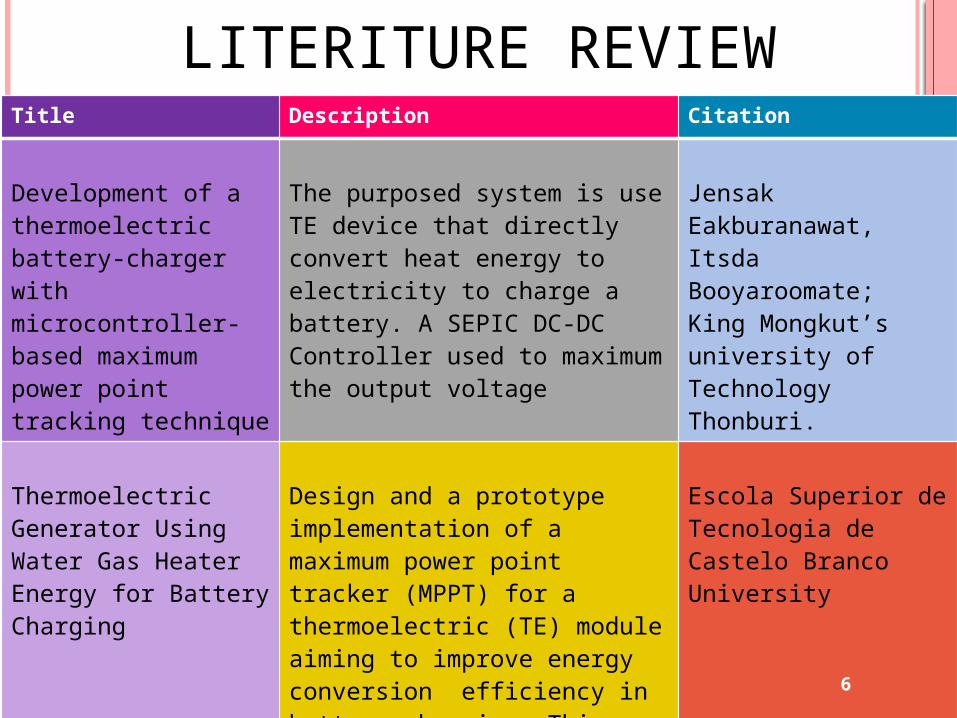
LITERITURE REVIEWTitle Description Citation
Development of a thermoelectric battery-charger with microcontroller-based maximum power point tracking technique
The purposed system is use TE device that directly convert heat energy to electricity to charge a battery. A SEPIC DC-DC Controller used to maximum the output voltage
Jensak Eakburanawat, Itsda Booyaroomate;King Mongkut’s university of Technology Thonburi.
Thermoelectric Generator Using Water Gas Heater Energy for Battery Charging
Design and a prototype implementation of a maximum power point tracker (MPPT) for a thermoelectric (TE) module aiming to improve energy conversion efficiency in battery charging. This system uses TE devices that directly convert heat energy from a water gas heater to electricity to charge a battery.
Escola Superior de Tecnologia de Castelo Branco University
6

LITERITURE REVIEWTitle Description Citation
Modelling of thermoelectricdevices for electric power generation
The steam-Rankine cycle is the principle exploited for producing electric power from high temperature fluid streams. Gas and steam cogeneration and combined heat and power technologies (CHP) help to improve the electrical and total efficiencies of modern power plants from 35% to about 60%.
ANDREAS BITSCHIDipl.Ing., Technical University of Vienna
Stirling Engine – Bringing Electricity to Remote Locations
The alpha configuration locates the piston and the displacer in separate cylinders, and attaches the heater and the cold sink to either cylinder. Alpha engines have good reliability and efficiency. It used MATLAB to simulate data collection
Joshua Dulin,Matthew Hove,Jonathan D. Lilley;California Polytechnic State University, San Luis Obispo
7
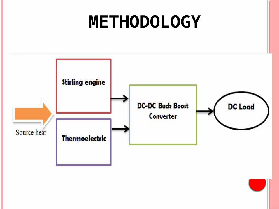
METHODOLOGY
8
9
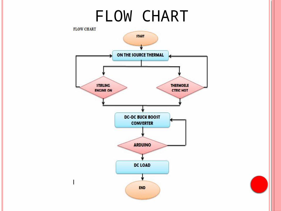
FLOW CHART
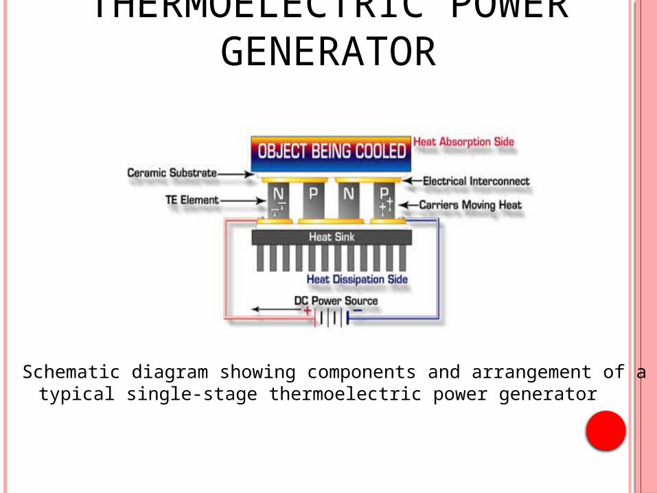
THERMOELECTRIC POWER GENERATOR
10
Schematic diagram showing components and arrangement of a typical single-stage thermoelectric power generator
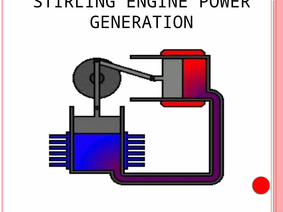
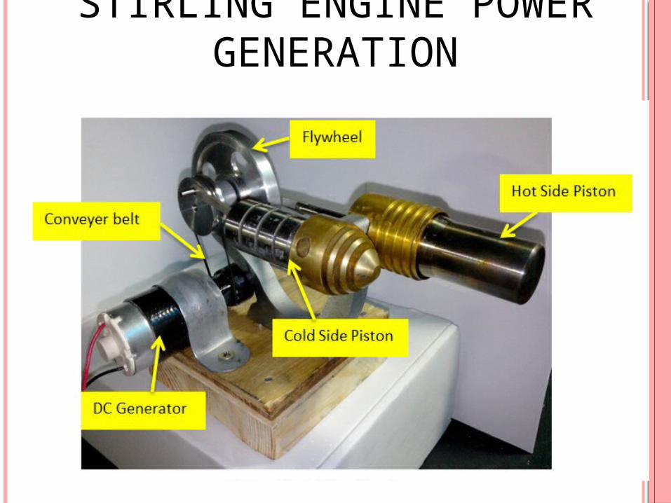
STIRLING ENGINE POWER GENERATION
11

12
RESULT & ANALYSIS
13
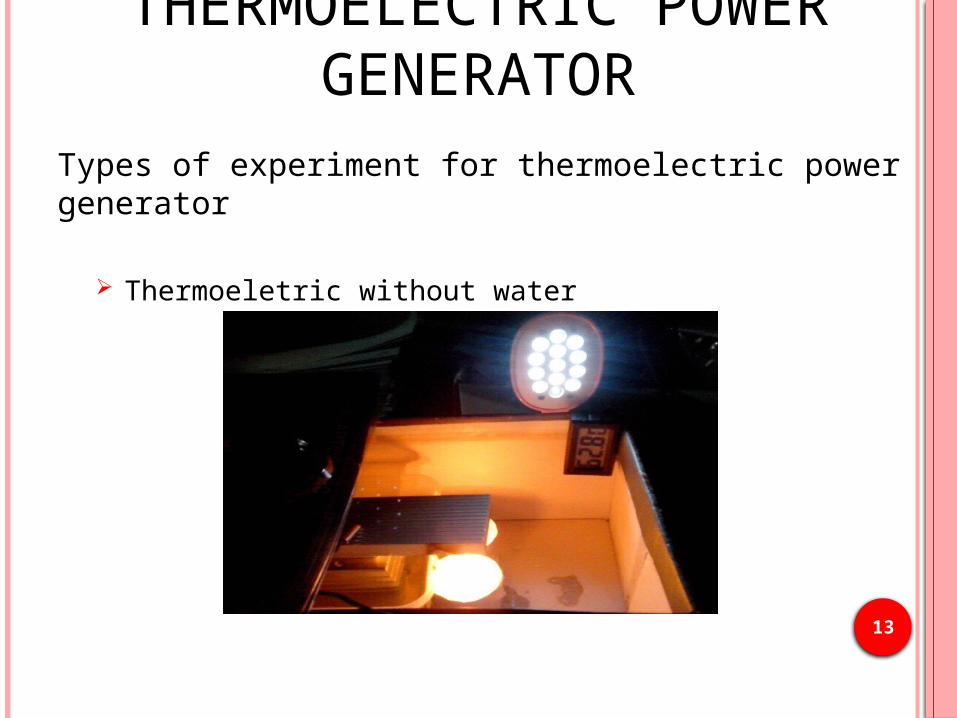
Types of experiment for thermoelectric power generator
Thermoeletric without water
THERMOELECTRIC POWER GENERATOR
14
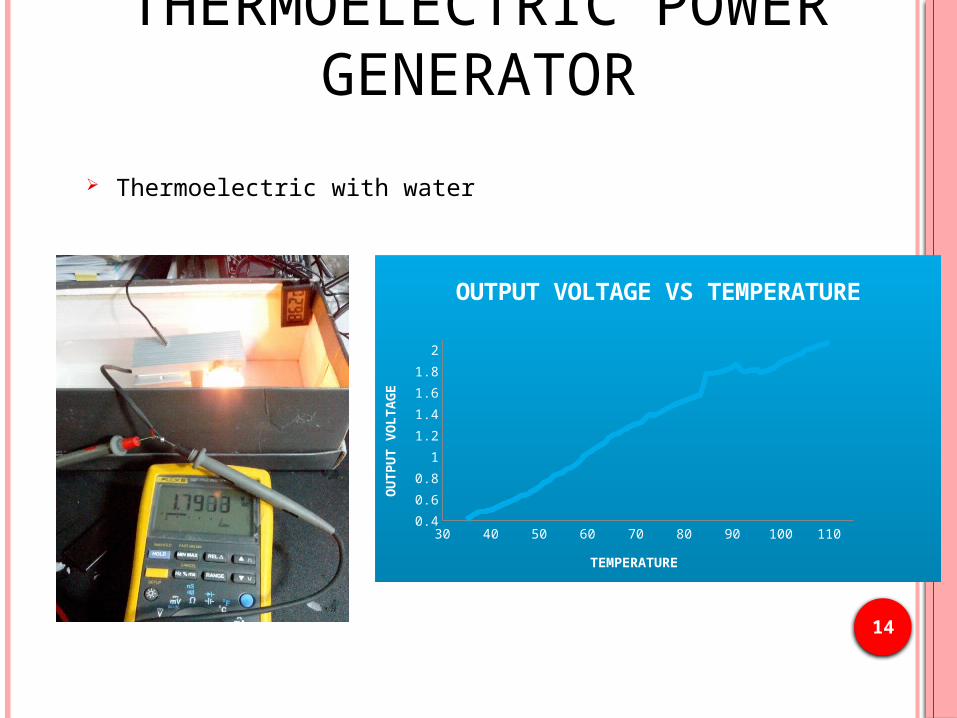
Thermoelectric with water
THERMOELECTRIC POWER GENERATOR
30 40 50 60 70 80 90 100 1100.4
0.6
0.8
1
1.2
1.4
1.6
1.8
2
OUTPUT VOLTAGE VS TEMPER-ATURE
TEMPERATURE
OU
TP
UT V
OLTA
GE
15
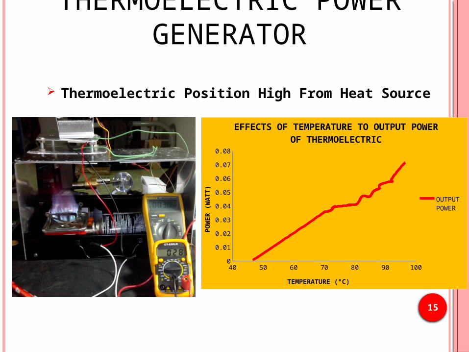
Thermoelectric Position High From Heat Source
THERMOELECTRIC POWER GENERATOR
40 50 60 70 80 90 1000
0.01
0.02
0.03
0.04
0.05
0.06
0.07
0.08
EFFECTS OF TEMPERATURE TO OUTPUT POWER OF THERMOELECTRIC
OUTPUT POWER
TEMPERATURE (°C)
PO
WER
(W
ATT)
16
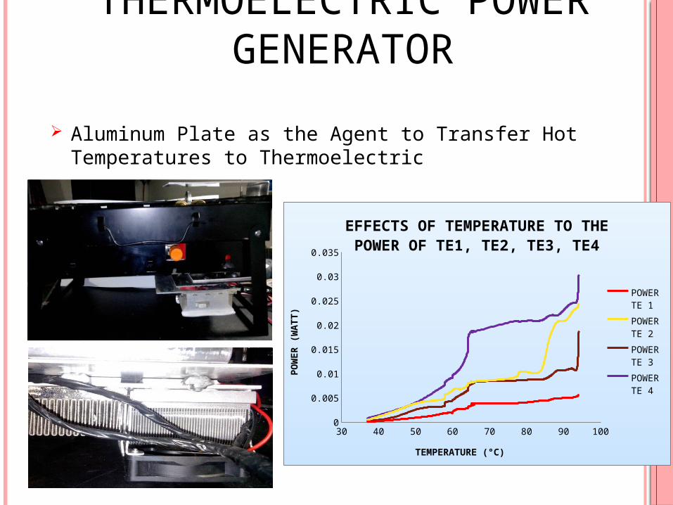
Aluminum Plate as the Agent to Transfer Hot Temperatures to Thermoelectric
THERMOELECTRIC POWER GENERATOR
30 40 50 60 70 80 90 1000
0.005
0.01
0.015
0.02
0.025
0.03
0.035
EFFECTS OF TEMPERATURE TO THE POWER OF TE1, TE2, TE3, TE4
POWER TE 1
POWER TE 2
POWER TE 3
POWER TE 4
TEMPERATURE (°C)
PO
WER
(W
ATT)
17
STIRLING ENGINE POWER GENERATION
18
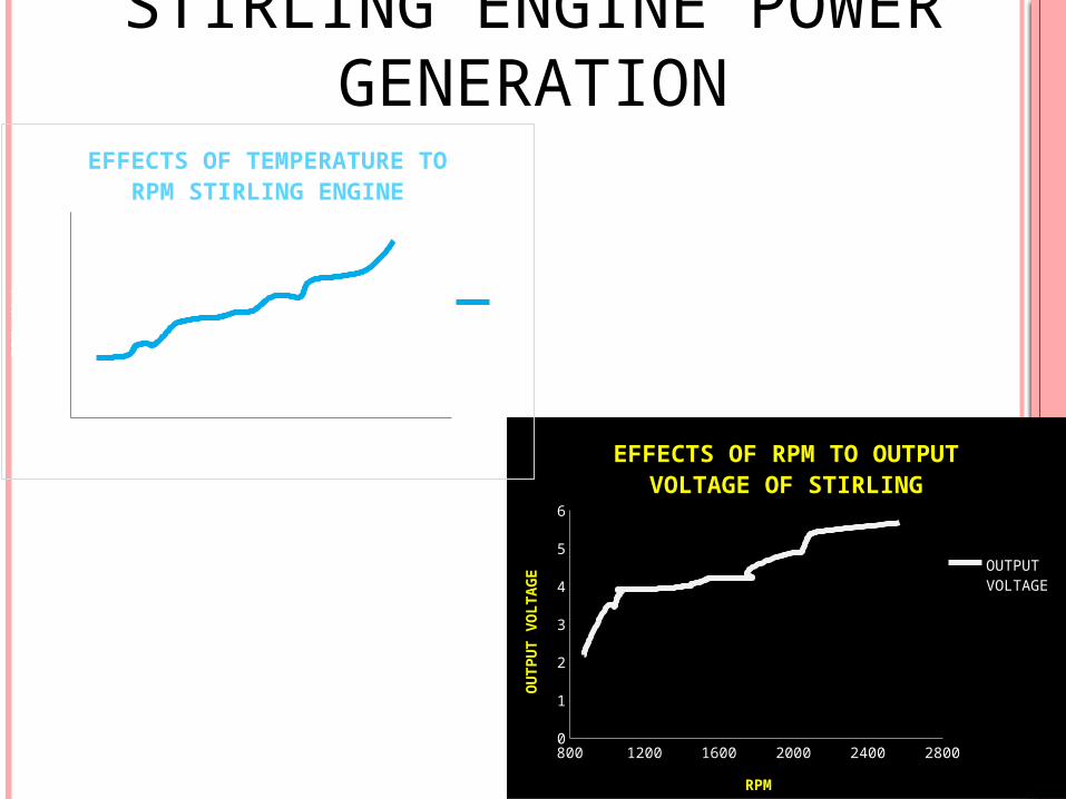
STIRLING ENGINE POWER GENERATION
800 1200 1600 2000 2400 28000
1
2
3
4
5
6
EFFECTS OF RPM TO OUTPUT VOLTAGE OF STIRLING
OUTPUT VOLTAGE
RPM
OU
TP
UT V
OLTA
GE
50 80 110 140 170 200 230 260 2900
500
1000
1500
2000
2500
3000
EFFECTS OF TEMPERATURE TO RPM STIRLING ENGINE
RPM
TEMPERATURE (°C)
RP
M (
Wm
)

19
CIRCUIT DC-DC BUCK BOOST CONVERTER
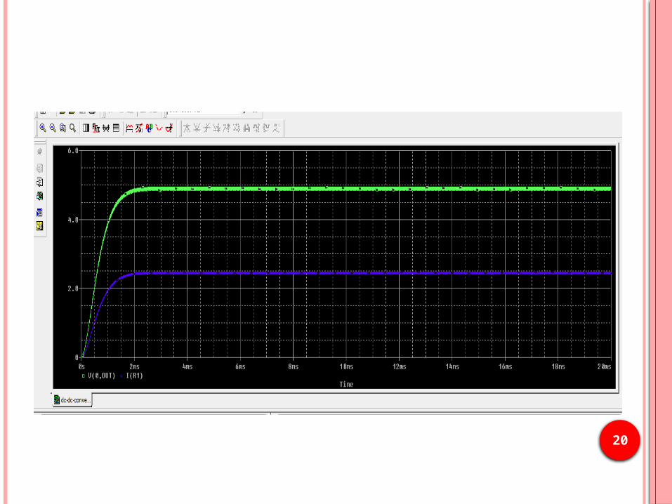
20

21
CONCLUSION
• The design could be able to produce a new hybrid power generation system of thermoelectric and Stirling engine.
• Optimize the power output for hybrid power generation system.
22
REFERENCES Anders Killander, John C Bass. A stove-top generator for cold areas. In:
Proceedings of the IEEE 15th international conference on thermoelectrics; 1996. p. 390–3.
Mahmudur R, Roger S. Thermoelectric power-generation for battery
charging. In: Proceedings of the IEEE conference on energy management and power delivery, vol. 1; 1995. p. 186–91.
A Coreless Maximum Power Point Tracking Circuit of Thermoelectric Generators for Battery Charging Systems Sungkyu Cho, Namjae Kim, Soonseo Park and Shiho Kim Dept. of Electrical Engineering, Chungbuk National University, Chungbuk, 361-763, Korea. Email : {saladn, njk84, transistor, shiho}@chungbuk.ac.kr
Dr. John Walsh, "Basic principles of operation and applications of the Stirling engine from its invention in 1816 to its modern uses ". Limerick Institute of Technology, Department of Mechanical and Automobile Engineering, School of Science, Engineering and Information Technology.Engineering Technology Teachers Association Conference 2012, pp. 1-22, 01-Oct-2013.
23

Q & A
24


![Design and Evaluation of a MEMS-Based Stirling Microcooler...[1]. Thermoelectric energy conversion has low efficiency, however, resulting in significant power requirements and waste](https://img.pdfslide.us/doc/110x75/5ebd40cec46e79356f5cba91/design-and-evaluation-of-a-mems-based-stirling-microcooler-1-thermoelectric.jpg)