Embed Size (px)
DESCRIPTION
Customer Engineering
Citation preview
CUMMINS Customer Engineering
ISX15 (2013) Diesel Engine InstallationVolvo – VNL Heavy Duty Truck – 780
By Dibyajyoti Laha
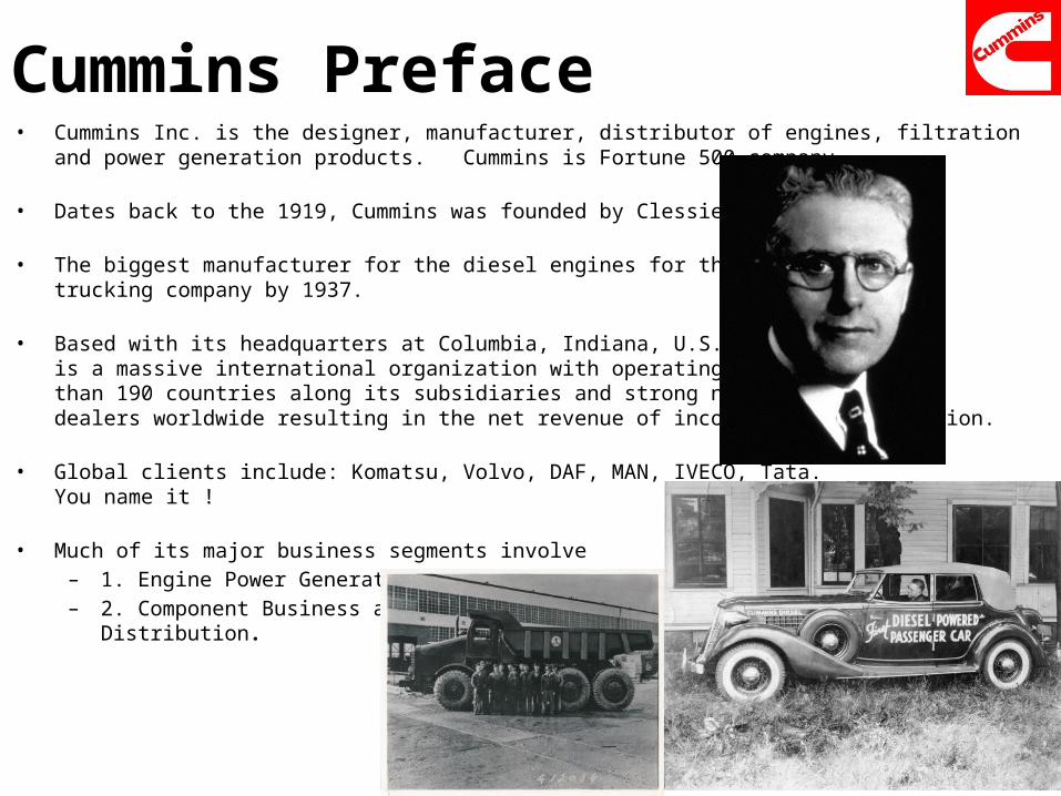
Cummins Preface• Cummins Inc. is the designer, manufacturer, distributor of engines, filtration and power generation products.
Cummins is Fortune 500 company.
• Dates back to the 1919, Cummins was founded by Clessie Cummins.
• The biggest manufacturer for the diesel engines for the trucking company by 1937.
• Based with its headquarters at Columbia, Indiana, U.S. Cummins Inc.is a massive international organization with operating overseas in more than 190 countries along its subsidiaries and strong network of 6000dealers worldwide resulting in the net revenue of income nearly $17 billion.
• Global clients include: Komatsu, Volvo, DAF, MAN, IVECO, Tata. You name it !
• Much of its major business segments involve– 1. Engine Power Generation– 2. Component Business and
Distribution.
Presentation Objective !
• Finding a Cummins designed diesel engine
• To pick an on highway application of the Cummins selected diesel engine.
• To explore the proper installation methods for the engine onto the vehicle using customer engineering prospects.
• Relatively, consideration for the smooth functionality of the engine for the client.
• To conclude the whole research of the customer engineering application for the engine to the client in 8 minutes.
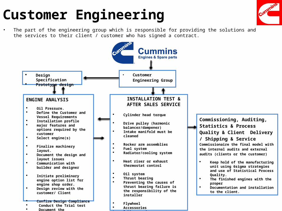
Customer Engineering • The part of the engineering group which is responsible for providing the solutions and the services to their client / customer who
has signed a contract.
• Customer Engineering Group
INSTALLATION TEST & AFTER SALES SERVICE
Cylinder head torque Drive pulley (harmonic
balancer/dampener) Intake manifold must be cleaned
Rocker arm assemblies Fuel system Radiator/cooling system
Heat riser or exhaust thermostat
control
Oil system Thrust bearing Preventing the causes of thrust
bearing failure is the responsibility of the installer
Flywheel Accessories Rubber goods
ENGINE ANALYSIS
Oil Pressure. Define the Customer and Vessel
Requirements Installation profile major features and options
required by the customer Select engine(s)
Finalize machinery layout. Document the design and layout
issues Communication with builder and
designer
Initiate preliminary engine option list for engine shop order.
Design review with the customer/ Client
Confirm Design Compliance Conduct the Trial test Document the Installation
Design Specification Prototype design
Commissioning, Auditing, Statistics & Process Quality & Client Delivery / Shipping & Service Commissionaire the final model with the internal audits and external audits (clients or the customer)
Keep hold of the manufacturing unit using 6sigma strategies and use of Statistical Process Quality.
The finished engines with the proper Documentation and installation to the
client.
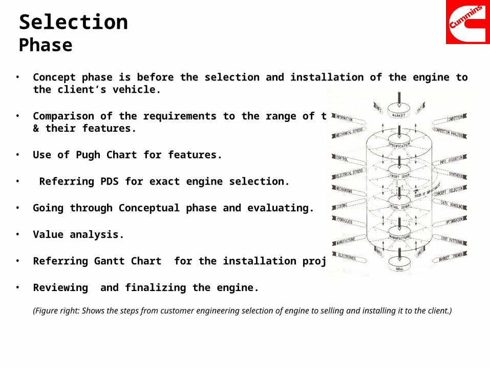
SelectionPhase
• Concept phase is before the selection and installation of the engine to the client’s vehicle.
• Comparison of the requirements to the range of the engines& their features.
• Use of Pugh Chart for features.
• Referring PDS for exact engine selection.
• Going through Conceptual phase and evaluating.
• Value analysis.
• Referring Gantt Chart for the installation project.
• Reviewing and finalizing the engine.
(Figure right: Shows the steps from customer engineering selection of engine to selling and installing it to the client.)
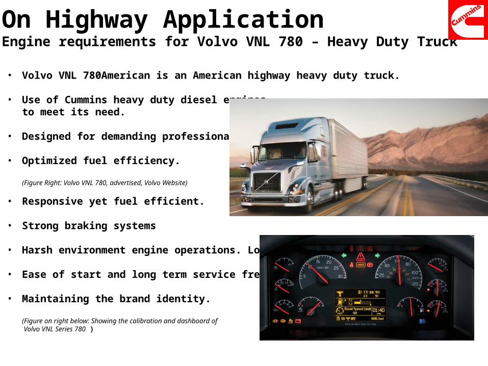
On Highway ApplicationEngine requirements for Volvo VNL 780 – Heavy Duty Truck
• Volvo VNL 780American is an American highway heavy duty truck.
• Use of Cummins heavy duty diesel enginesto meet its need.
• Designed for demanding professional drivers.
• Optimized fuel efficiency.
(Figure Right: Volvo VNL 780, advertised, Volvo Website)
• Responsive yet fuel efficient.
• Strong braking systems
• Harsh environment engine operations. Long run.
• Ease of start and long term service free engines.
• Maintaining the brand identity.
(Figure on right below: Showing the calibration and dashboard of Volvo VNL Series 780 )
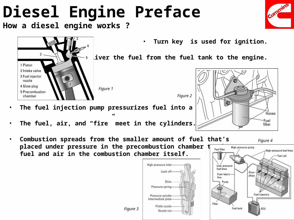
Diesel Engine PrefaceHow a diesel engine works ?
• Turn key is used for ignition.
• Fuel pumps deliver the fuel from the fuel tank to the engine.
• The fuel injection pump pressurizes fuel into a delivery tube.
• The fuel, air, and “fire” meet in the cylinders.
• Combustion spreads from the smaller amount of fuel that’splaced under pressure in the precombustion chamber to thefuel and air in the combustion chamber itself.
Figure 1
Figure 2
Figure 3
Figure 4
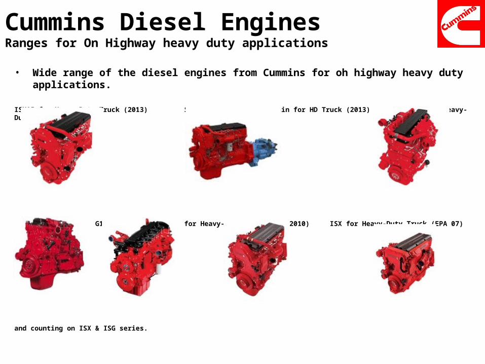
Cummins Diesel EnginesRanges for On Highway heavy duty applications
• Wide range of the diesel engines from Cummins for oh highway heavy duty applications.
ISX15 for Heavy-Duty Truck (2013) SmartAdvantage™ Powertrain for HD Truck (2013) ISX12 for Heavy-Duty Truck (2013)
ISX12 G ISG11/12 ISX15 for Heavy-Duty Truck (EPA 2010) ISX for Heavy-Duty Truck (EPA 07)
and counting on ISX & ISG series.
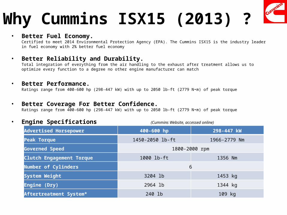
Why Cummins ISX15 (2013) ? • Better Fuel Economy.
Certified to meet 2014 Environmental Protection Agency (EPA). The Cummins ISX15 is the industry leader in fuel economy with 2% better fuel economy
• Better Reliability and Durability.Total integration of everything from the air handling to the exhaust after treatment allows us to optimize every function to a degree no other engine manufacturer can match
• Better Performance.Ratings range from 400-600 hp (298-447 kW) with up to 2050 lb-ft (2779 N•m) of peak torque
• Better Coverage For Better Confidence.Ratings range from 400-600 hp (298-447 kW) with up to 2050 lb-ft (2779 N•m) of peak torque
• Engine Specifications (Cummins Website, accessed online)
Advertised Horsepower 400-600 hp 298-447 kW
Peak Torque 1450-2050 lb-ft 1966-2779 Nm
Governed Speed 1800-2000 rpm
Clutch Engagement Torque 1000 lb-ft 1356 Nm
Number of Cylinders 6
System Weight 3204 lb 1453 kg
Engine (Dry) 2964 lb 1344 kg
Aftertreatment System* 240 lb 109 kg
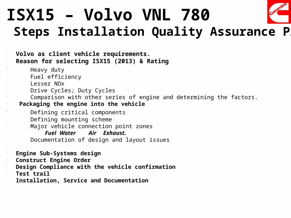
ISX15 – Volvo VNL 780 Steps Installation Quality Assurance Process• Volvo as client vehicle requirements. • Reason for selecting ISX15 (2013) & Rating • Heavy duty• Fuel efficiency • Lesser NOx• Drive Cycles; Duty Cycles• Comparison with other series of engine and determining the factors. • Packaging the engine into the vehicle• Defining critical components• Defining mounting scheme• Major vehicle connection point zones• Fuel Water Air Exhaust. • Documentation of design and layout issues•
• Engine Sub-Systems design• Construct Engine Order• Design Compliance with the vehicle confirmation • Test trail • Installation, Service and Documentation
Installation Factors For ISX15 (2013) On Volvo VNL 780
• Engine mounting system• Drivetrain• Engine driven accessories • Exhaust system• Cooling system• Air intake system• Fuel system• Electrical system• Starting system• Electronic control system• Controls, gauges, and alarms• Lubrication system• Documentation • Test trail/ test run
For a successful installation of the engine on to the Volvo VNL 780 the above factors play an important role apart from certain considerations mentioned at the end of presentation.
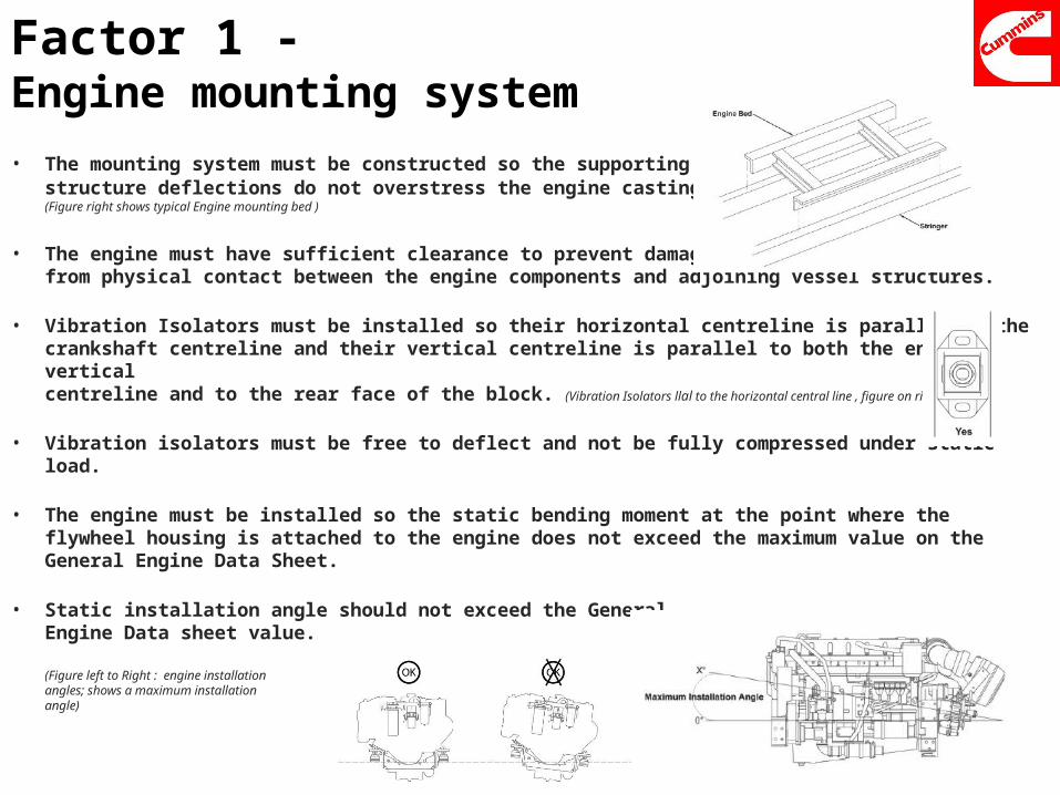
Factor 1 - Engine mounting system• The mounting system must be constructed so the supporting
structure deflections do not overstress the engine castings.(Figure right shows typical Engine mounting bed )
• The engine must have sufficient clearance to prevent damage from physical contact between the engine components and adjoining vessel structures.
• Vibration Isolators must be installed so their horizontal centreline is parallel to thecrankshaft centreline and their vertical centreline is parallel to both the engine vertical centreline and to the rear face of the block. (Vibration Isolators llal to the horizontal central line , figure on right)
• Vibration isolators must be free to deflect and not be fully compressed under static load.
• The engine must be installed so the static bending moment at the point where the flywheel housing is attached to the engine does not exceed the maximum value on the General Engine Data Sheet.
• Static installation angle should not exceed the General Engine Data sheet value.
(Figure left to Right : engine installation angles; shows a maximum installation angle)
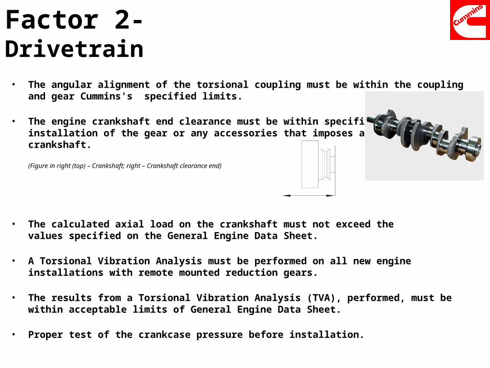
Factor 2- Drivetrain• The angular alignment of the torsional coupling must be within the coupling and gear Cummins's
specified limits.
• The engine crankshaft end clearance must be within specifications after installation of the gear or any accessories that imposes an axial load on thecrankshaft.
(Figure in right (top) – Crankshaft; right – Crankshaft clearance end)
• The calculated axial load on the crankshaft must not exceed thevalues specified on the General Engine Data Sheet.
• A Torsional Vibration Analysis must be performed on all new engine installations with remote mounted reduction gears.
• The results from a Torsional Vibration Analysis (TVA), performed, must be within acceptable limits of General Engine Data Sheet.
• Proper test of the crankcase pressure before installation.
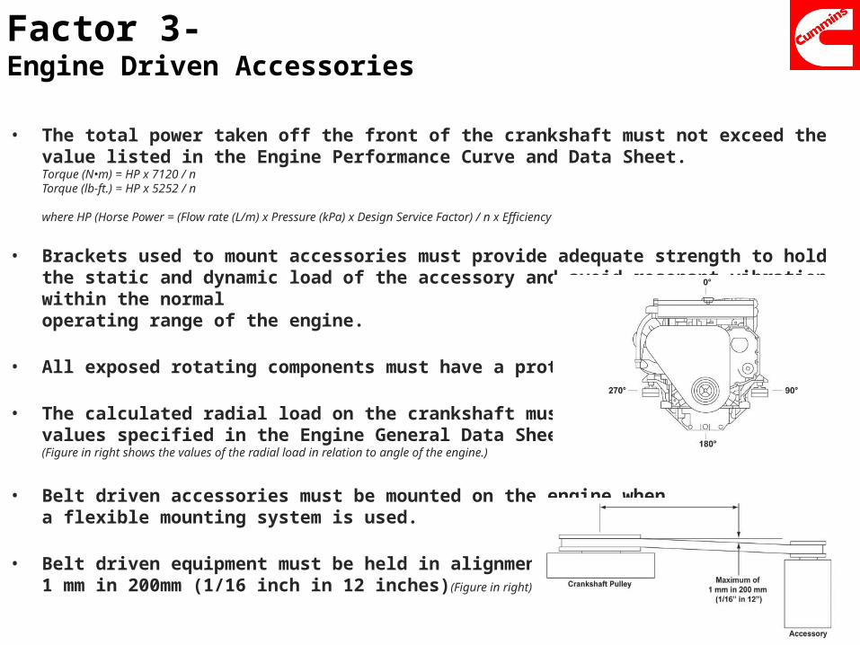
Factor 3- Engine Driven Accessories
• The total power taken off the front of the crankshaft must not exceed the value listed in the Engine Performance Curve and Data Sheet.Torque (N•m) = HP x 7120 / n Torque (lb-ft.) = HP x 5252 / n
where HP (Horse Power = (Flow rate (L/m) x Pressure (kPa) x Design Service Factor) / n x Efficiency
• Brackets used to mount accessories must provide adequate strength to hold the static and dynamic load of the accessory and avoid resonant vibration within the normal operating range of the engine.
• All exposed rotating components must have a protective guard.
• The calculated radial load on the crankshaft must not exceed the values specified in the Engine General Data Sheet.(Figure in right shows the values of the radial load in relation to angle of the engine.)
• Belt driven accessories must be mounted on the engine whena flexible mounting system is used.
• Belt driven equipment must be held in alignment to a tolerance of1 mm in 200mm (1/16 inch in 12 inches)(Figure in right)
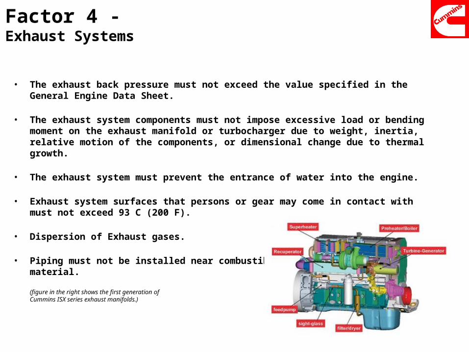
Factor 4 - Exhaust Systems
• The exhaust back pressure must not exceed the value specified in the General Engine Data Sheet.
• The exhaust system components must not impose excessive load or bending moment on the exhaust manifold or turbocharger due to weight, inertia, relative motion of the components, or dimensional change due to thermal growth.
• The exhaust system must prevent the entrance of water into the engine.
• Exhaust system surfaces that persons or gear may come in contact with must not exceed 93 C (200 F).
• Dispersion of Exhaust gases.
• Piping must not be installed near combustiblematerial.
(figure in the right shows the first generation of Cummins ISX series exhaust manifolds.)
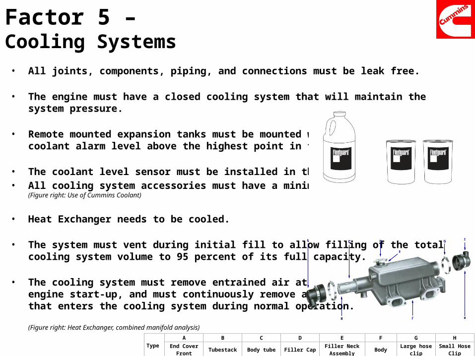
Factor 5 – Cooling Systems • All joints, components, piping, and connections must be leak free.
• The engine must have a closed cooling system that will maintain the system pressure.
• Remote mounted expansion tanks must be mounted with the low coolant alarm level above the highest point in the cooling system.
• The coolant level sensor must be installed in the expansion tank.• All cooling system accessories must have a minimum pressure rating.
(Figure right: Use of Cummins Coolant)
• Heat Exchanger needs to be cooled.
• The system must vent during initial fill to allow filling of the totalcooling system volume to 95 percent of its full capacity.
• The cooling system must remove entrained air at engine start-up, and must continuously remove airthat enters the cooling system during normal operation.
(Figure right: Heat Exchanger, combined manifold analysis)
Type A B C D E F G H
End Cover Front Tubestack Body tube Filler Cap Filler Neck Assembly Body Large hose clip Small Hose Clip
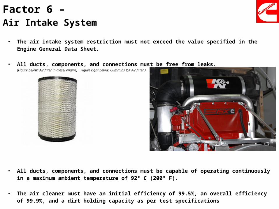
Factor 6 – Air Intake System
• The air intake system restriction must not exceed the value specified in the Engine General Data Sheet.
• All ducts, components, and connections must be free from leaks.(Figure below: Air filter in diesel engine; Figure right below: Cummins ISX Air filter )
• All ducts, components, and connections must be capable of operating continuously in a maximum ambient temperature of 92° C (200° F).
• The air cleaner must have an initial efficiency of 99.5%, an overall efficiency of 99.9%, and a dirt holding capacity as per test specifications
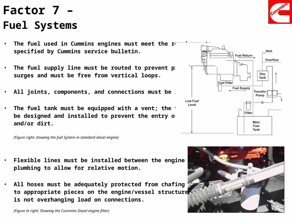
Factor 7 – Fuel Systems• The fuel used in Cummins engines must meet the requirements
specified by Cummins service bulletin.
• The fuel supply line must be routed to prevent pressuresurges and must be free from vertical loops.
• All joints, components, and connections must be leak free.
• The fuel tank must be equipped with a vent; the vent must be designed and installed to prevent the entry of water and/or dirt.
(Figure right: showing the fuel System in standard diesel engine)
• Flexible lines must be installed between the engine and vessel plumbing to allow for relative motion.
• All hoses must be adequately protected from chafing and clipped to appropriate pieces on the engine/vessel structure such that there is not overhanging load on connections.
(Figure in right: Showing the Cummins Diesel engine filter)
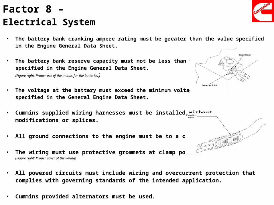
Factor 8 –Electrical System• The battery bank cranking ampere rating must be greater than the value specified in the Engine General
Data Sheet.
• The battery bank reserve capacity must not be less than the value specified in the Engine General Data Sheet.(Figure right: Proper use of the metals for the batteries.)
• The voltage at the battery must exceed the minimum voltagespecified in the General Engine Data Sheet.
• Cummins supplied wiring harnesses must be installed without modifications or splices.
• All ground connections to the engine must be to a common point.
• The wiring must use protective grommets at clamp points.(Figure right: Proper cover of the wiring)
• All powered circuits must include wiring and overcurrent protection that complies with governing standards of the intended application.
• Cummins provided alternators must be used.
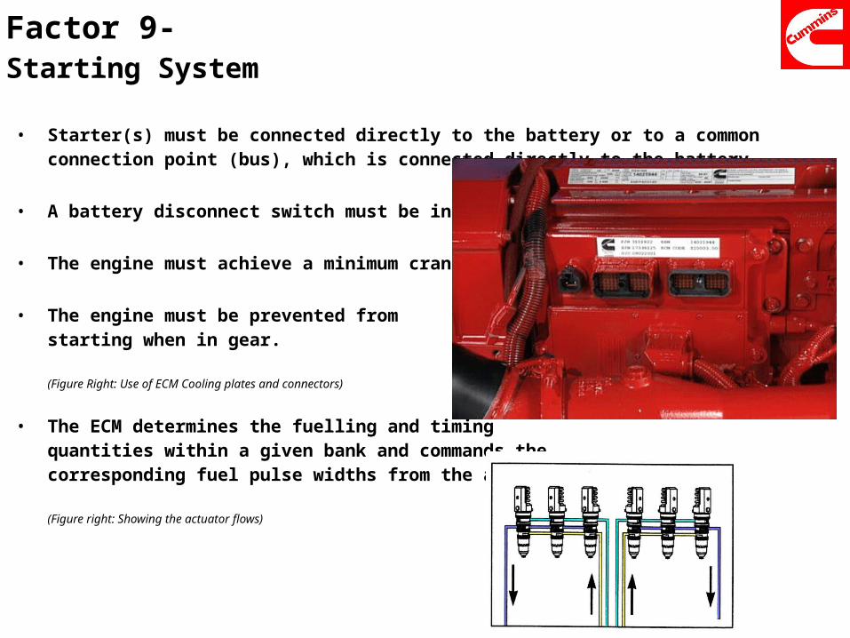
Factor 9- Starting System
• Starter(s) must be connected directly to the battery or to a common connection point (bus), which is connected directly to the battery.
• A battery disconnect switch must be installed.
• The engine must achieve a minimum cranking speed
• The engine must be prevented from starting when in gear.
(Figure Right: Use of ECM Cooling plates and connectors)
• The ECM determines the fuelling and timing quantities within a given bank and commands thecorresponding fuel pulse widths from the actuators.
(Figure right: Showing the actuator flows)
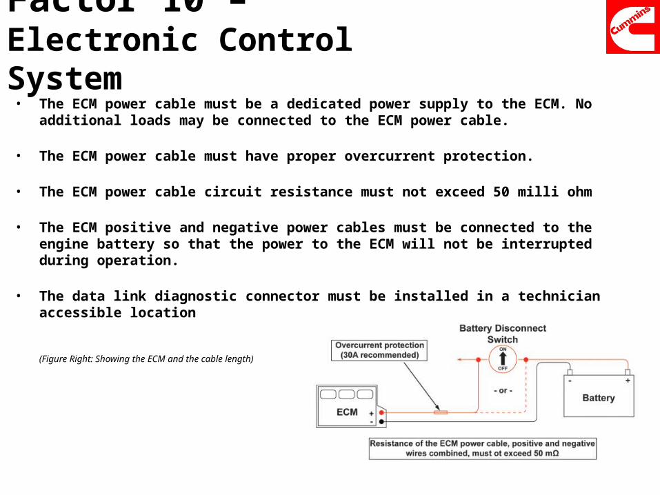
Factor 10 – Electronic Control System• The ECM power cable must be a dedicated power supply to the ECM. No additional loads may be
connected to the ECM power cable.
• The ECM power cable must have proper overcurrent protection.
• The ECM power cable circuit resistance must not exceed 50 milli ohm
• The ECM positive and negative power cables must be connected to the engine battery so that the power to the ECM will not be interrupted during operation.
• The data link diagnostic connector must be installed in a technician accessible location
(Figure Right: Showing the ECM and the cable length)
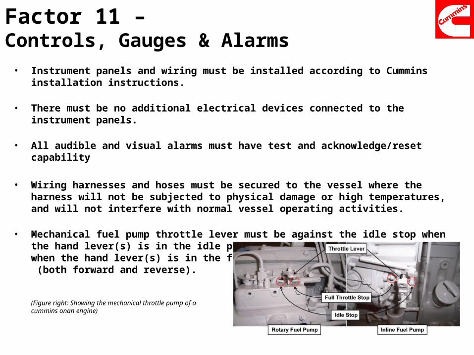
Factor 11 –Controls, Gauges & Alarms• Instrument panels and wiring must be installed according to Cummins installation instructions.
• There must be no additional electrical devices connected to the instrument panels.
• All audible and visual alarms must have test and acknowledge/reset capability
• Wiring harnesses and hoses must be secured to the vessel where the harness will not be subjected to physical damage or high temperatures, and will not interfere with normal vessel operating activities.
• Mechanical fuel pump throttle lever must be against the idle stop when the hand lever(s) is in the idle position and against the wide open stop when the hand lever(s) is in the fuel throttle position (both forward and reverse).
(Figure right: Showing the mechanical throttle pump of a cummins onan engine)
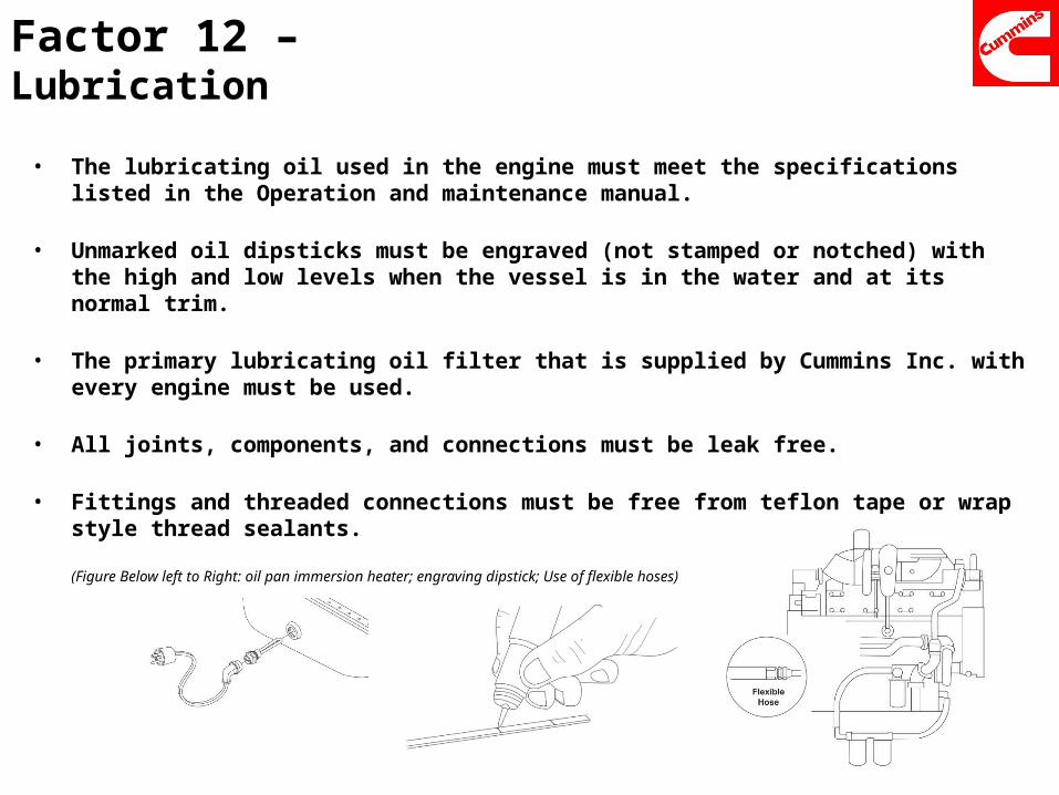
Factor 12 –Lubrication
• The lubricating oil used in the engine must meet the specifications listed in the Operation and maintenance manual.
• Unmarked oil dipsticks must be engraved (not stamped or notched) with the high and low levels when the vessel is in the water and at its normal trim.
• The primary lubricating oil filter that is supplied by Cummins Inc. with every engine must be used.
• All joints, components, and connections must be leak free.
• Fittings and threaded connections must be free from teflon tape or wrap style thread sealants.
(Figure Below left to Right: oil pan immersion heater; engraving dipstick; Use of flexible hoses)
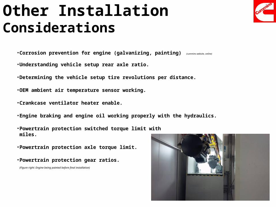
Other Installation Considerations
• Corrosion prevention for engine (galvanizing, painting) (cummins website, online)
• Understanding vehicle setup rear axle ratio.
• Determining the vehicle setup tire revolutions per distance.
• OEM ambient air temperature sensor working.
• Crankcase ventilator heater enable.
• Engine braking and engine oil working properly with the hydraulics.
• Powertrain protection switched torque limit withmiles.
• Powertrain protection axle torque limit.
• Powertrain protection gear ratios.(Figure right: Engine being painted before final installation)
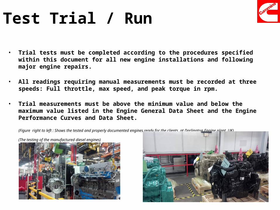
Test Trial / Run
• Trial tests must be completed according to the procedures specified within this document for all new engine installations and following major engine repairs.
• All readings requiring manual measurements must be recorded at three speeds: Full throttle, max speed, and peak torque in rpm.
• Trial measurements must be above the minimum value and below the maximum value listed in the Engine General Data Sheet and the Engine Performance Curves and Data Sheet.
(Figure right to left : Shows the tested and properly documented engines ready for the clients, at Darlington Engine plant, UK)
(The testing of the manufactured diesel engines)
Other FactorsAfter Sales Service & Marketing
• Non-Cummins Inc. supplied hoses and fittings connected to the engine or gear must comply with the standards of Cummins ISX15.
• Promotion of the engine by providing a service operation for 5 years.
• Free service of the engine up to 3 years or 100,000 miles.
• Cummins Care.
• Ease of servicing ports and service station locations within reachable access.
• Proper documentation of the product’s test and service to Volvo.
• Cummins ISX15 EPA certification 2013. Greener technology solution with negligible amount of NOx. & diesel particulate emissions. Complying the EU laws.
• Engine security features & anti theft control features.
References • Cummins Engine Website: http://cumminsengines.com/isx15-heavy-duty-truck-2013?#
specifications [Accessed online. 16th April 2014]
• Cummins Inc. – History
• Cummins On highway Application. Website : http://cumminsengines.com/powerspec-isx-vehicle-setup [Accessed online. 20th April 2014]
• Volvo heavy duty trucks. Website: http://www.volvotrucks.com/trucks/na/en-us/products/vnl/vnl780/Pages/vnl780.aspx [Accessed online. 20th April 2014]
• Cummins diesel engine understanding. Website: http://www.cumminspowersouth.com/CPSU/ [Accessed online 21st April 2014]

End of Presentation
Questions ?