Embed Size (px)
Citation preview

Creo Parametric
Tips and Tricks
Evan Winter
PTC

2
System
3
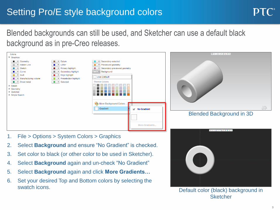
1. File > Options > System Colors > Graphics
2. Select Background and ensure “No Gradient” is checked.
3. Set color to black (or other color to be used in Sketcher).
4. Select Background again and un-check “No Gradient”
5. Select Background again and click More Gradients…
6. Set your desired Top and Bottom colors by selecting the
swatch icons.
Setting Pro/E style background colors
Blended backgrounds can still be used, and Sketcher can use a default black
background as in pre-Creo releases.
Blended Background in 3D
Default color (black) background in
Sketcher
4
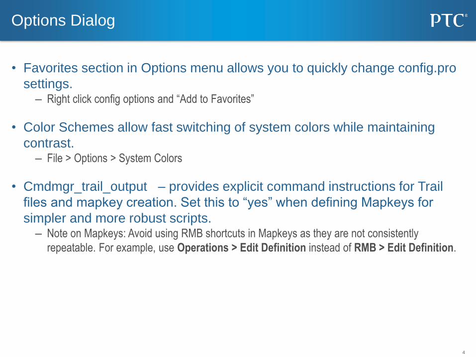
• Favorites section in Options menu allows you to quickly change config.pro
settings. – Right click config options and “Add to Favorites”
• Color Schemes allow fast switching of system colors while maintaining
contrast. – File > Options > System Colors
• Cmdmgr_trail_output – provides explicit command instructions for Trail
files and mapkey creation. Set this to “yes” when defining Mapkeys for
simpler and more robust scripts. – Note on Mapkeys: Avoid using RMB shortcuts in Mapkeys as they are not consistently
repeatable. For example, use Operations > Edit Definition instead of RMB > Edit Definition.
Options Dialog
5
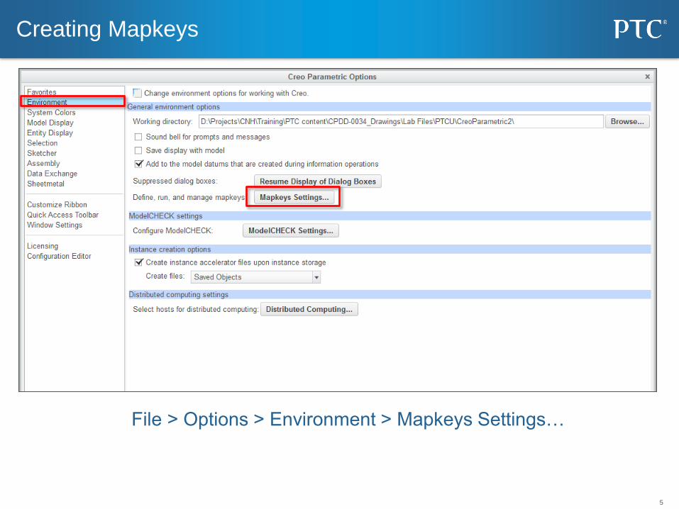
File > Options > Environment > Mapkeys Settings…
Creating Mapkeys
6
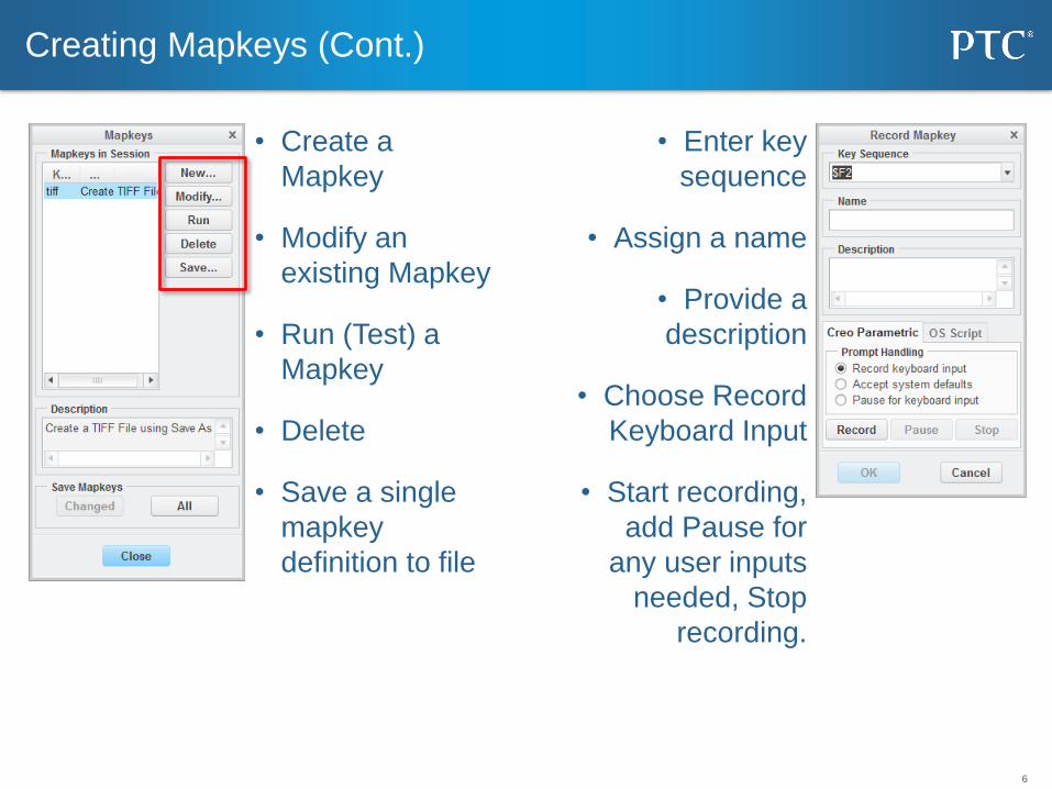
• Create a
Mapkey
• Modify an
existing Mapkey
• Run (Test) a
Mapkey
• Delete
• Save a single
mapkey
definition to file
Creating Mapkeys (Cont.)
• Enter key
sequence
• Assign a name
• Provide a
description
• Choose Record
Keyboard Input
• Start recording,
add Pause for
any user inputs
needed, Stop
recording.
7
Creating Mapkeys (Cont.)
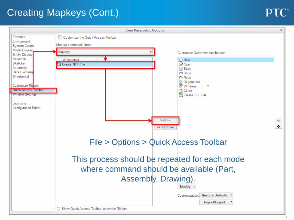
File > Options > Quick Access Toolbar
This process should be repeated for each mode
where command should be available (Part,
Assembly, Drawing).
8
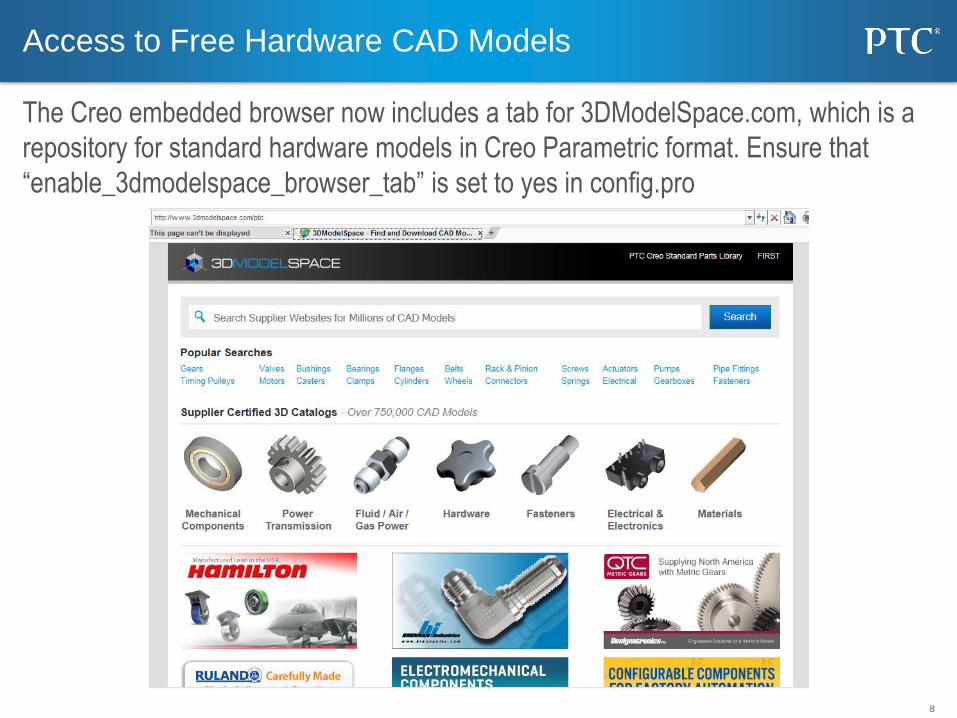
Access to Free Hardware CAD Models
The Creo embedded browser now includes a tab for 3DModelSpace.com, which is a
repository for standard hardware models in Creo Parametric format. Ensure that
“enable_3dmodelspace_browser_tab” is set to yes in config.pro

9
Part
10
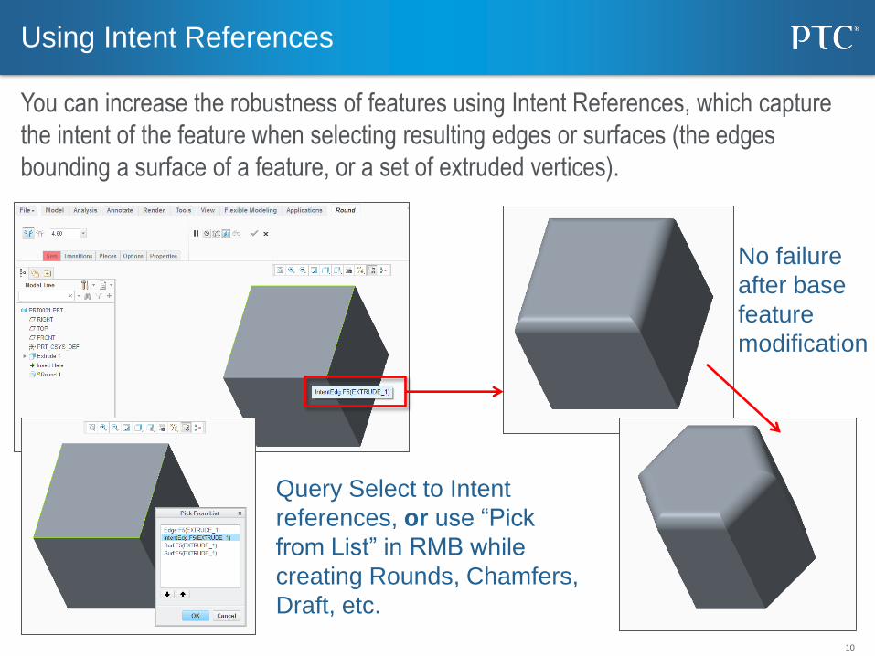
Query Select to Intent
references, or use “Pick
from List” in RMB while
creating Rounds, Chamfers,
Draft, etc.
Using Intent References
You can increase the robustness of features using Intent References, which capture
the intent of the feature when selecting resulting edges or surfaces (the edges
bounding a surface of a feature, or a set of extruded vertices).
No failure
after base
feature
modification
11
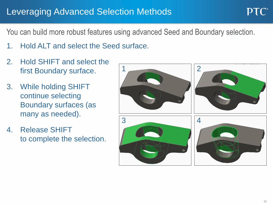
1. Hold ALT and select the Seed surface.
2. Hold SHIFT and select the
first Boundary surface.
3. While holding SHIFT
continue selecting
Boundary surfaces (as
many as needed).
4. Release SHIFT
to complete the selection.
Leveraging Advanced Selection Methods
You can build more robust features using advanced Seed and Boundary selection.
1 2
3 4
12
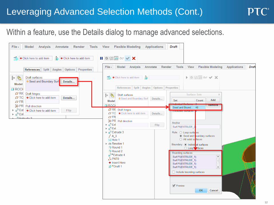
Leveraging Advanced Selection Methods (Cont.)
Within a feature, use the Details dialog to manage advanced selections.
13
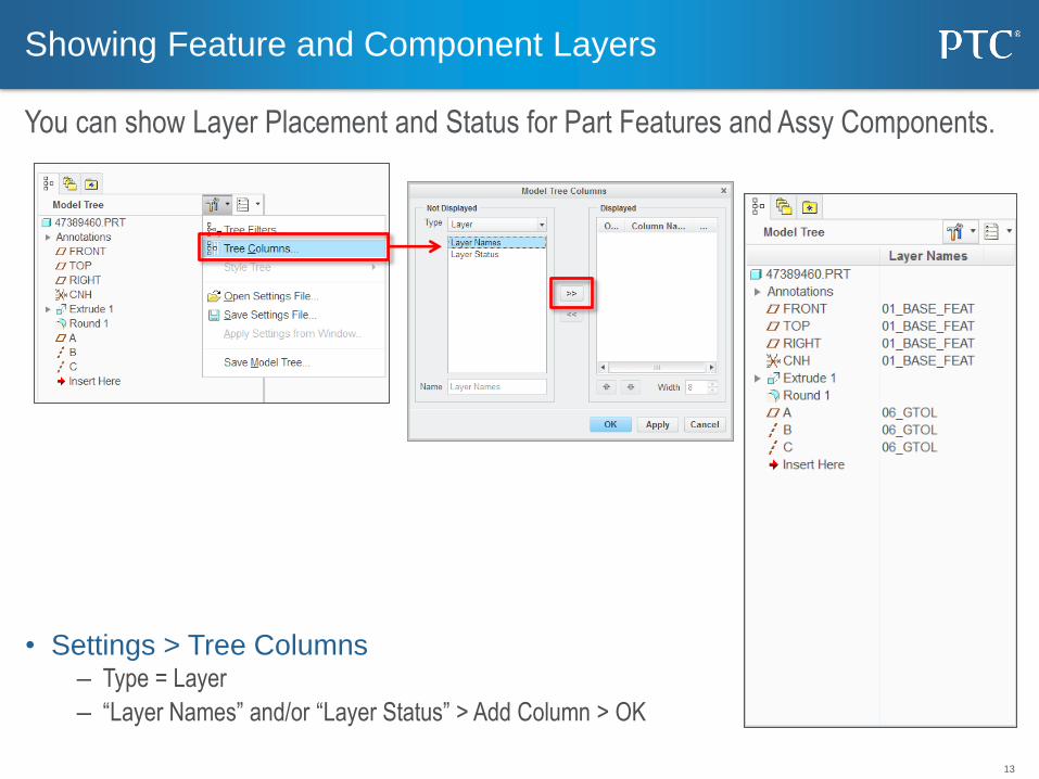
• Settings > Tree Columns – Type = Layer
– “Layer Names” and/or “Layer Status” > Add Column > OK
Showing Feature and Component Layers
You can show Layer Placement and Status for Part Features and Assy Components.
14
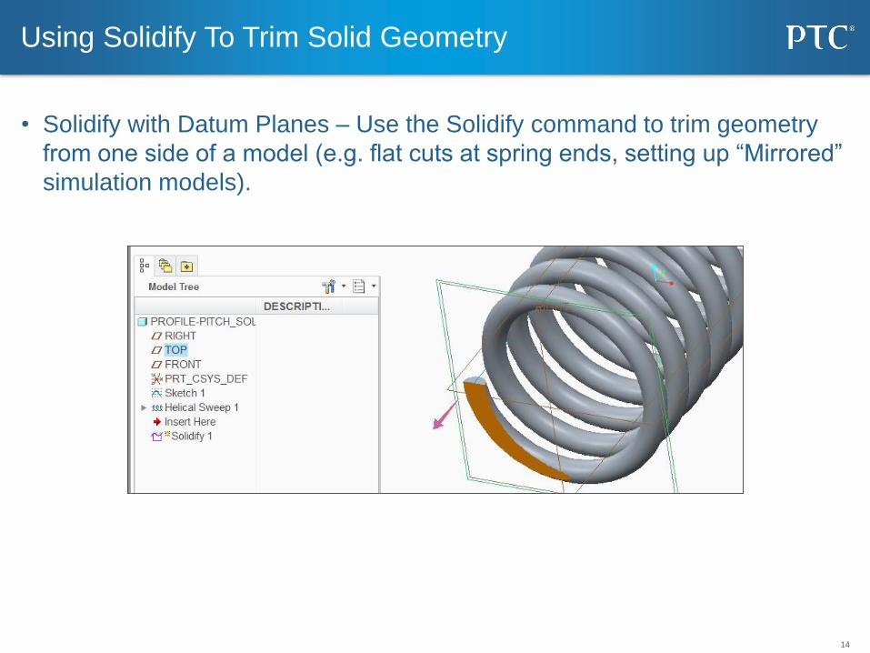
• Solidify with Datum Planes – Use the Solidify command to trim geometry
from one side of a model (e.g. flat cuts at spring ends, setting up “Mirrored”
simulation models).
Using Solidify To Trim Solid Geometry
15
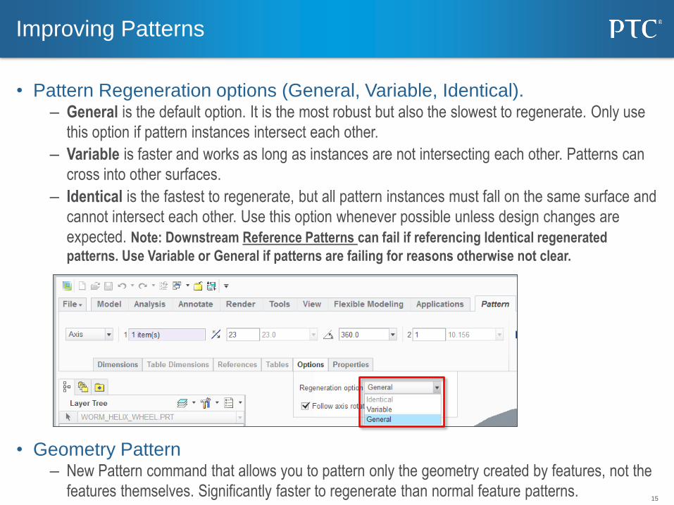
• Pattern Regeneration options (General, Variable, Identical). – General is the default option. It is the most robust but also the slowest to regenerate. Only use
this option if pattern instances intersect each other.
– Variable is faster and works as long as instances are not intersecting each other. Patterns can
cross into other surfaces.
– Identical is the fastest to regenerate, but all pattern instances must fall on the same surface and
cannot intersect each other. Use this option whenever possible unless design changes are
expected. Note: Downstream Reference Patterns can fail if referencing Identical regenerated
patterns. Use Variable or General if patterns are failing for reasons otherwise not clear.
• Geometry Pattern – New Pattern command that allows you to pattern only the geometry created by features, not the
features themselves. Significantly faster to regenerate than normal feature patterns.
Improving Patterns
16
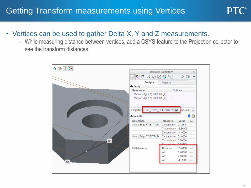
• Vertices can be used to gather Delta X, Y and Z measurements. – While measuring distance between vertices, add a CSYS feature to the Projection collector to
see the transform distances.
Getting Transform measurements using Vertices
17
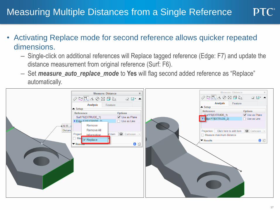
• Activating Replace mode for second reference allows quicker repeated
dimensions. – Single-click on additional references will Replace tagged reference (Edge: F7) and update the
distance measurement from original reference (Surf: F6).
– Set measure_auto_replace_mode to Yes will flag second added reference as “Replace”
automatically.
Measuring Multiple Distances from a Single Reference
18
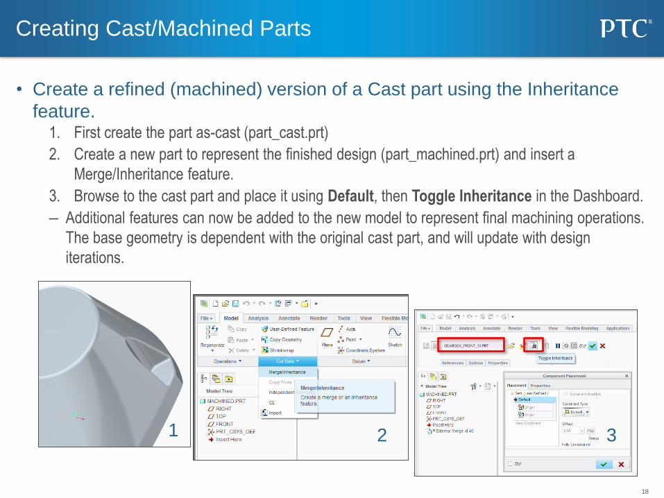
• Create a refined (machined) version of a Cast part using the Inheritance
feature. 1. First create the part as-cast (part_cast.prt)
2. Create a new part to represent the finished design (part_machined.prt) and insert a
Merge/Inheritance feature.
3. Browse to the cast part and place it using Default, then Toggle Inheritance in the Dashboard.
– Additional features can now be added to the new model to represent final machining operations.
The base geometry is dependent with the original cast part, and will update with design
iterations.
Creating Cast/Machined Parts
1 2 3
19
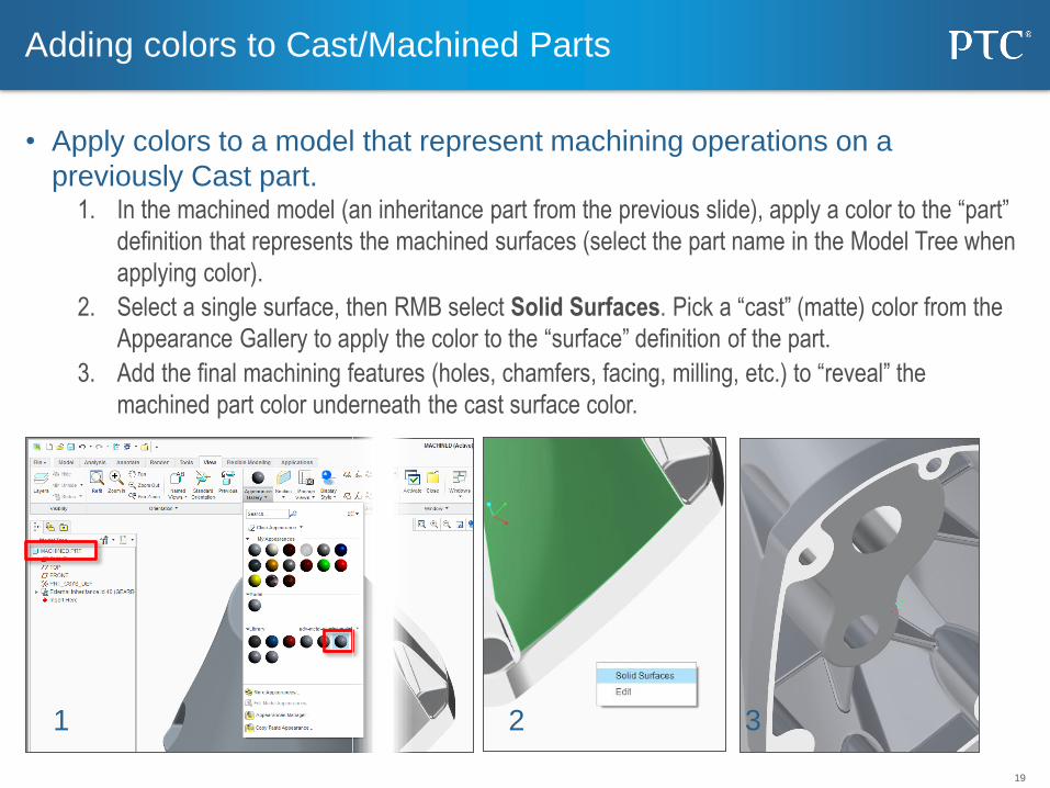
• Apply colors to a model that represent machining operations on a
previously Cast part. 1. In the machined model (an inheritance part from the previous slide), apply a color to the “part”
definition that represents the machined surfaces (select the part name in the Model Tree when
applying color).
2. Select a single surface, then RMB select Solid Surfaces. Pick a “cast” (matte) color from the
Appearance Gallery to apply the color to the “surface” definition of the part.
3. Add the final machining features (holes, chamfers, facing, milling, etc.) to “reveal” the
machined part color underneath the cast surface color.
Adding colors to Cast/Machined Parts
1 2 3

20
Assembly
21
• Set auto_constr_always_use_offset to Never – Coincident will be the default constraint type for the following reference pairs:
• Planes
• Linear edges / Datum Axis
• Planes combined with Linear edges
• Set auto_constr_always_use_offset to Yes – Offset (Angle or Normal) will be the default constraint type for the following reference pairs, never coincident:
• Planes
• Linear edges / Datum Axis
• Planes combined with Linear edges
• Set auto_constr_always_use_offset to No* – Creo will suggest a constraint type based on current component position and orientation
• Coincident
• Distance
• Angle
• Normal
– Setting up the orientation tolerance is done with the 3 additional config.pro options on the next
slide.
Assembly Constraint Tweaking
Use these options to change how constraints are applied by default.

22
• Check if position fits Angle or Normal. For this use values set for options: – comp_angle_offset_eps (“-1” seems to work ok)
– comp_normal_offset_eps (“-91” seems to work ok)
• If position does not fit Angle or Normal, then it will be either Coincident or Distance.
Here decision is made based on the value of: – auto_constr_offset_tolerance = (0.5 of the model size by default). If initial distance is bigger than this value, you will
receive Distance, if less, Coincident.
– Note: Value is relative to the size of each component being assembled.
Assembly Constraint Tweaking (Cont.)
Use these options whenever “auto_constr_always_use_offset” is set to No* .
23
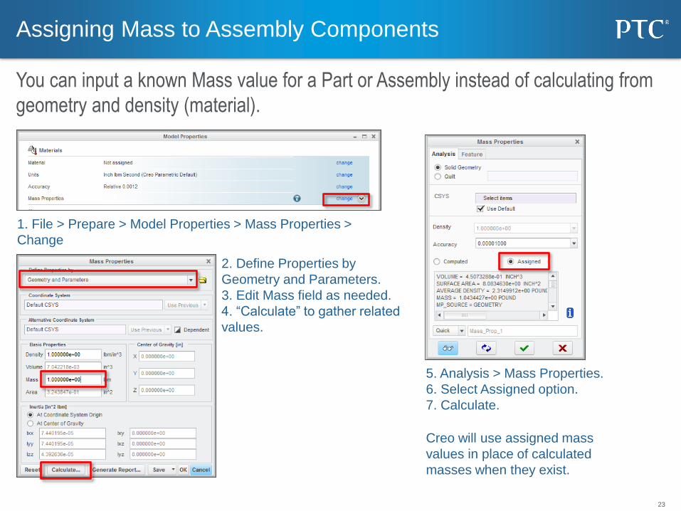
Assigning Mass to Assembly Components
You can input a known Mass value for a Part or Assembly instead of calculating from
geometry and density (material).
1. File > Prepare > Model Properties > Mass Properties >
Change
2. Define Properties by
Geometry and Parameters.
3. Edit Mass field as needed.
4. “Calculate” to gather related
values.
5. Analysis > Mass Properties.
6. Select Assigned option.
7. Calculate.
Creo will use assigned mass
values in place of calculated
masses when they exist.
24
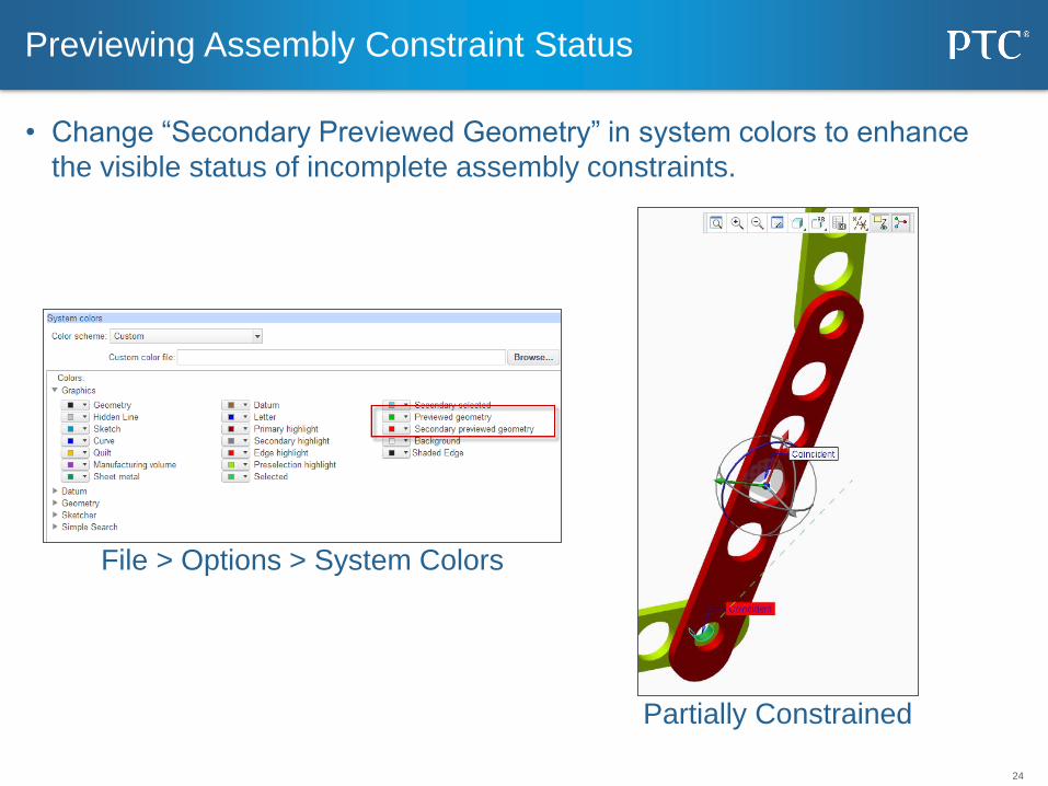
• Change “Secondary Previewed Geometry” in system colors to enhance
the visible status of incomplete assembly constraints.
Previewing Assembly Constraint Status
Partially Constrained
File > Options > System Colors
25
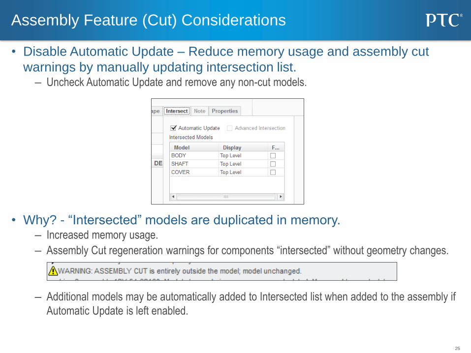
• Disable Automatic Update – Reduce memory usage and assembly cut
warnings by manually updating intersection list. – Uncheck Automatic Update and remove any non-cut models.
• Why? - “Intersected” models are duplicated in memory. – Increased memory usage.
– Assembly Cut regeneration warnings for components “intersected” without geometry changes.
– Additional models may be automatically added to Intersected list when added to the assembly if
Automatic Update is left enabled.
Assembly Feature (Cut) Considerations
26
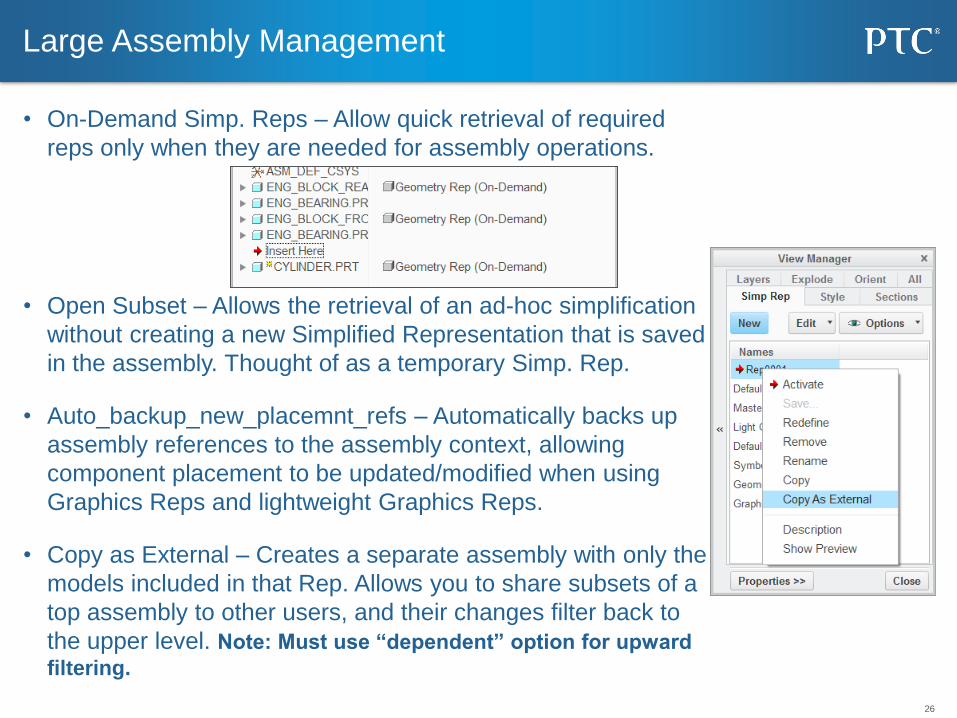
• On-Demand Simp. Reps – Allow quick retrieval of required
reps only when they are needed for assembly operations.
• Open Subset – Allows the retrieval of an ad-hoc simplification
without creating a new Simplified Representation that is saved
in the assembly. Thought of as a temporary Simp. Rep.
• Auto_backup_new_placemnt_refs – Automatically backs up
assembly references to the assembly context, allowing
component placement to be updated/modified when using
Graphics Reps and lightweight Graphics Reps.
• Copy as External – Creates a separate assembly with only the
models included in that Rep. Allows you to share subsets of a
top assembly to other users, and their changes filter back to
the upper level. Note: Must use “dependent” option for upward
filtering.
Large Assembly Management
27
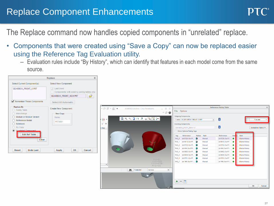
• Components that were created using “Save a Copy” can now be replaced easier
using the Reference Tag Evaluation utility. – Evaluation rules include “By History”, which can identify that features in each model come from the same
source.
Replace Component Enhancements
The Replace command now handles copied components in “unrelated” replace.

28
Options Modeler
29
• template_cnfg_asm – Specifies the default configurable product template file.
• template_module – Specifies the default module template file
Config.pro Options
30
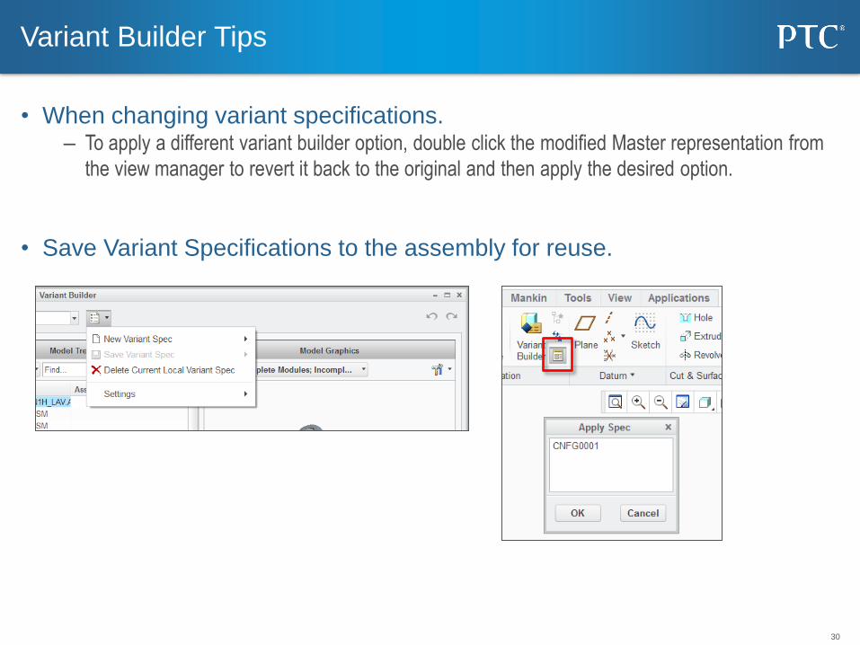
• When changing variant specifications. – To apply a different variant builder option, double click the modified Master representation from
the view manager to revert it back to the original and then apply the desired option.
• Save Variant Specifications to the assembly for reuse.
Variant Builder Tips
31
• Overbuilt Assemblies 1. (Top Level) File > Save As > Save As Configurable Product
2. (Overbuilt Components) RMB > Transfer into Module
• Interchange Assemblies – File > Save As > Save As Configurable Module
Legacy Data

32
Mechanism
33
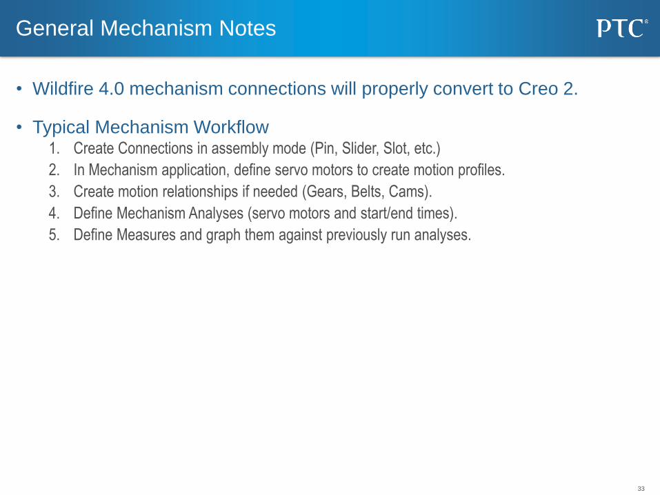
• Wildfire 4.0 mechanism connections will properly convert to Creo 2.
• Typical Mechanism Workflow 1. Create Connections in assembly mode (Pin, Slider, Slot, etc.)
2. In Mechanism application, define servo motors to create motion profiles.
3. Create motion relationships if needed (Gears, Belts, Cams).
4. Define Mechanism Analyses (servo motors and start/end times).
5. Define Measures and graph them against previously run analyses.
General Mechanism Notes
34
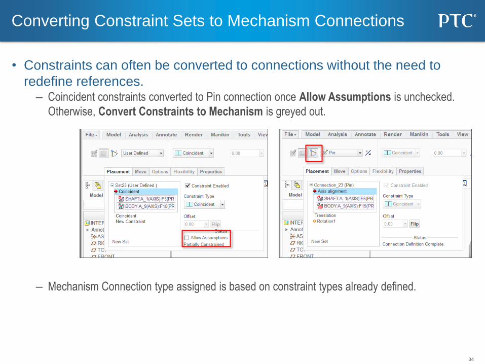
• Constraints can often be converted to connections without the need to
redefine references. – Coincident constraints converted to Pin connection once Allow Assumptions is unchecked.
Otherwise, Convert Constraints to Mechanism is greyed out.
– Mechanism Connection type assigned is based on constraint types already defined.
Converting Constraint Sets to Mechanism Connections
35
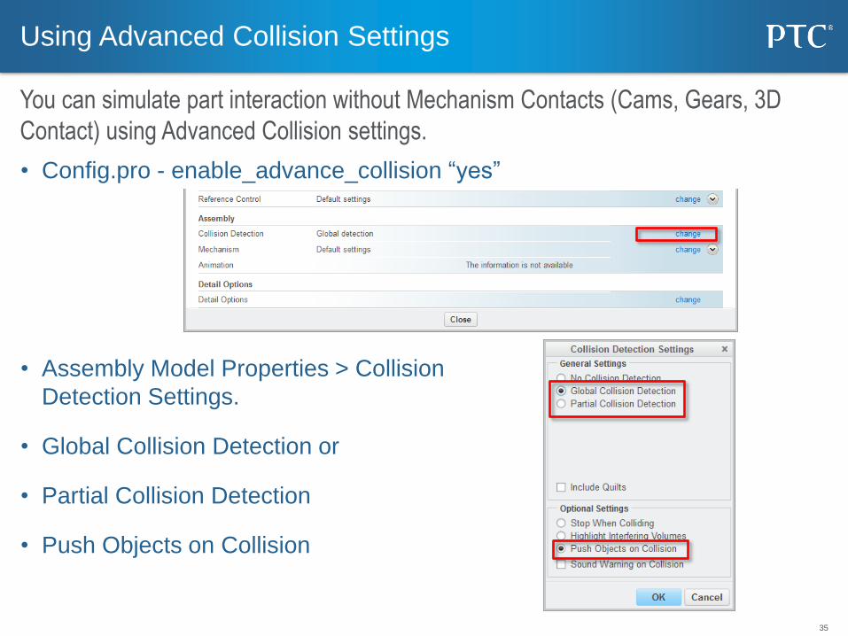
• Config.pro - enable_advance_collision “yes”
• Assembly Model Properties > Collision
Detection Settings.
• Global Collision Detection or
• Partial Collision Detection
• Push Objects on Collision
Using Advanced Collision Settings
You can simulate part interaction without Mechanism Contacts (Cams, Gears, 3D
Contact) using Advanced Collision settings.
36
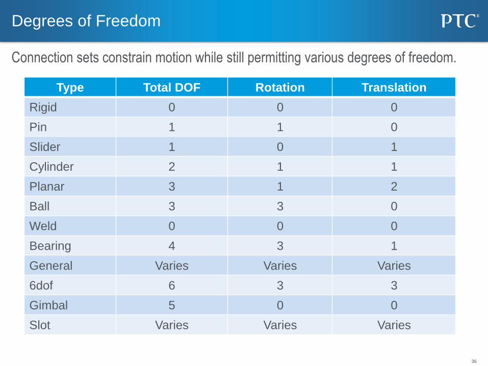
Type Total DOF Rotation Translation
Rigid 0 0 0
Pin 1 1 0
Slider 1 0 1
Cylinder 2 1 1
Planar 3 1 2
Ball 3 3 0
Weld 0 0 0
Bearing 4 3 1
General Varies Varies Varies
6dof 6 3 3
Gimbal 5 0 0
Slot Varies Varies Varies
Degrees of Freedom
Connection sets constrain motion while still permitting various degrees of freedom.
37
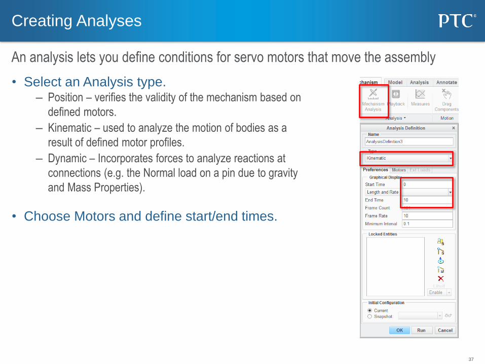
Creating Analyses
An analysis lets you define conditions for servo motors that move the assembly
• Select an Analysis type. – Position – verifies the validity of the mechanism based on
defined motors.
– Kinematic – used to analyze the motion of bodies as a
result of defined motor profiles.
– Dynamic – Incorporates forces to analyze reactions at
connections (e.g. the Normal load on a pin due to gravity
and Mass Properties).
• Choose Motors and define start/end times.
38
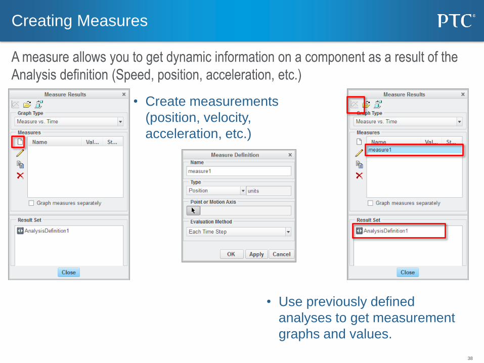
Creating Measures
A measure allows you to get dynamic information on a component as a result of the
Analysis definition (Speed, position, acceleration, etc.)
• Create measurements
(position, velocity,
acceleration, etc.)
• Use previously defined
analyses to get measurement
graphs and values.
39
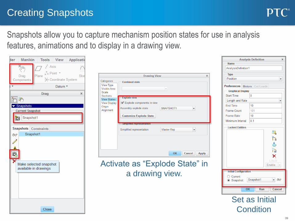
Creating Snapshots
Snapshots allow you to capture mechanism position states for use in analysis
features, animations and to display in a drawing view.
Activate as “Explode State” in
a drawing view.
Set as Initial
Condition

40
Drawings
41
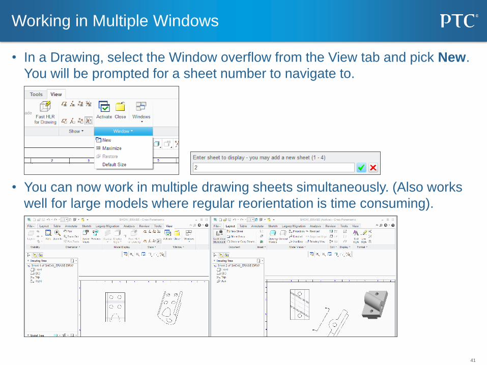
• In a Drawing, select the Window overflow from the View tab and pick New.
You will be prompted for a sheet number to navigate to.
• You can now work in multiple drawing sheets simultaneously. (Also works
well for large models where regular reorientation is time consuming).
Working in Multiple Windows
42
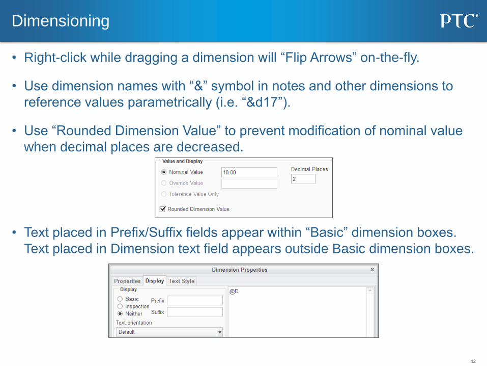
• Right-click while dragging a dimension will “Flip Arrows” on-the-fly.
• Use dimension names with “&” symbol in notes and other dimensions to
reference values parametrically (i.e. “&d17”).
• Use “Rounded Dimension Value” to prevent modification of nominal value
when decimal places are decreased.
• Text placed in Prefix/Suffix fields appear within “Basic” dimension boxes.
Text placed in Dimension text field appears outside Basic dimension boxes.
Dimensioning
43
• Allow_refs_to_geom_reps_in_drws – Controls whether dimensions and
notes can be created in views using Geometry Reps. Care should be taken
as dimensions and annotations may not update if geometry changes.
• Auto_regen_views – Sets whether drawing views update automatically
when changing sheets or windows. Set to no, drawing views must be
updated manually, but large drawing performance is dramatically improved.
• Hlr_for_quilts – Determines if HLR is performed on quilt features.
• Save_display – Saves the display of drawing items such as notes and
dimensions so that they are shown when a drawing is retrieved in read-only
mode.
• Force_Wireframe_in_drawings
Managing Large Drawings (Config.pro Options)
44
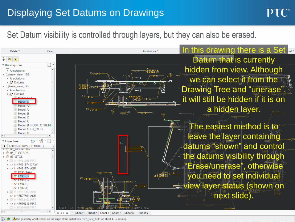
In this drawing there is a Set
Datum that is currently
hidden from view. Although
we can select it from the
Drawing Tree and “unerase”,
it will still be hidden if it is on
a hidden layer.
The easiest method is to
leave the layer containing
datums “shown” and control
the datums visibility through
“Erase/unerase”, otherwise
you need to set individual
view layer status (shown on
next slide).
Displaying Set Datums on Drawings
Set Datum visibility is controlled through layers, but they can also be erased.
45
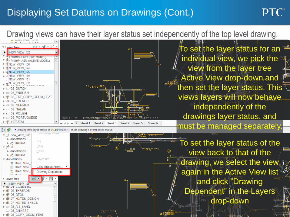
To set the layer status for an
individual view, we pick the
view from the layer tree
Active View drop-down and
then set the layer status. This
views layers will now behave
independently of the
drawings layer status, and
must be managed separately.
To set the layer status of the
view back to that of the
drawing, we select the view
again in the Active View list
and click “Drawing
Dependent” in the Layers
drop-down
Displaying Set Datums on Drawings (Cont.)
Drawing views can have their layer status set independently of the top level drawing.
46
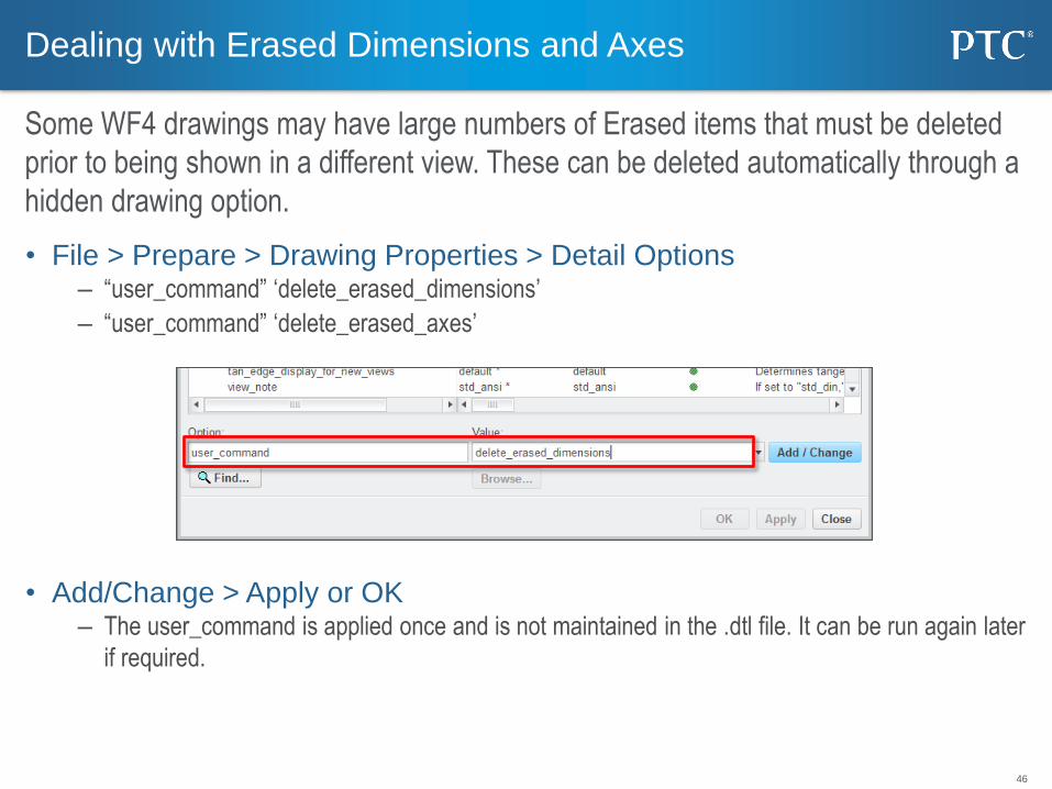
• File > Prepare > Drawing Properties > Detail Options – “user_command” ‘delete_erased_dimensions’
– “user_command” ‘delete_erased_axes’
• Add/Change > Apply or OK – The user_command is applied once and is not maintained in the .dtl file. It can be run again later
if required.
Dealing with Erased Dimensions and Axes
Some WF4 drawings may have large numbers of Erased items that must be deleted
prior to being shown in a different view. These can be deleted automatically through a
hidden drawing option.
47
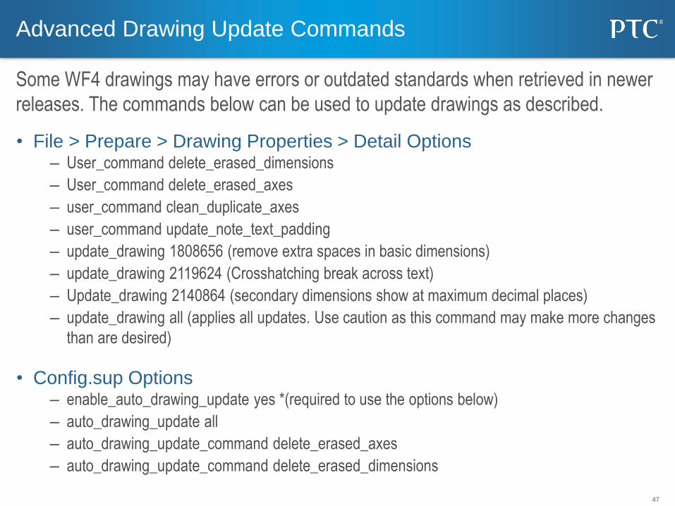
• File > Prepare > Drawing Properties > Detail Options – User_command delete_erased_dimensions
– User_command delete_erased_axes
– user_command clean_duplicate_axes
– user_command update_note_text_padding
– update_drawing 1808656 (remove extra spaces in basic dimensions)
– update_drawing 2119624 (Crosshatching break across text)
– Update_drawing 2140864 (secondary dimensions show at maximum decimal places)
– update_drawing all (applies all updates. Use caution as this command may make more changes
than are desired)
• Config.sup Options – enable_auto_drawing_update yes *(required to use the options below)
– auto_drawing_update all
– auto_drawing_update_command delete_erased_axes
– auto_drawing_update_command delete_erased_dimensions
Advanced Drawing Update Commands
Some WF4 drawings may have errors or outdated standards when retrieved in newer
releases. The commands below can be used to update drawings as described.
48
• Under Table > Repeat region > Attributes select the table region > No
dup/Level > Recursive > bln by part > No cbl Info > done/return > done – The BOM table will now be sorted by Assembly sequence.
Sorting BOM tables by Assembly Sequence
Repeat Regions in BOM tables often sort alphabetically rather than by assembly
sequence. This can be changed through the Repeat Region Attributes.

49
Sketcher
50
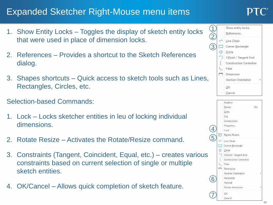
1. Show Entity Locks – Toggles the display of sketch entity locks
that were used in place of dimension locks.
2. References – Provides a shortcut to the Sketch References
dialog.
3. Shapes shortcuts – Quick access to sketch tools such as Lines,
Rectangles, Circles, etc.
Selection-based Commands:
1. Lock – Locks sketcher entities in leu of locking individual
dimensions.
2. Rotate Resize – Activates the Rotate/Resize command.
3. Constraints (Tangent, Coincident, Equal, etc.) – creates various
constraints based on current selection of single or multiple
sketch entities.
4. OK/Cancel – Allows quick completion of sketch feature.
Expanded Sketcher Right-Mouse menu items
1
2
3
4
5
6
7
51
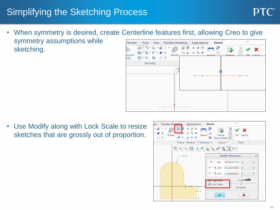
• When symmetry is desired, create Centerline features first, allowing Creo to give
symmetry assumptions while
sketching.
• Use Modify along with Lock Scale to resize
sketches that are grossly out of proportion.
Simplifying the Sketching Process
52
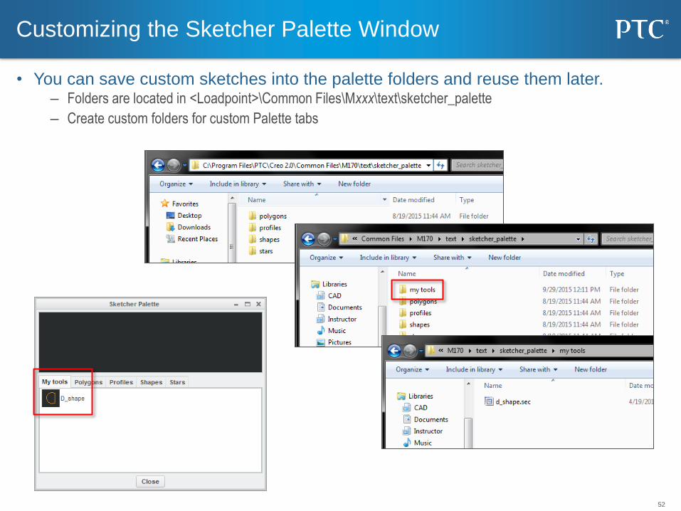
• You can save custom sketches into the palette folders and reuse them later. – Folders are located in <Loadpoint>\Common Files\Mxxx\text\sketcher_palette
– Create custom folders for custom Palette tabs
Customizing the Sketcher Palette Window

53
Resolving Failures
54
• Regen_failure_handling – No_resolve_mode*
– Resolve_mode
Specifies whether to enter resolve mode when regeneration failures occur.
Resolve_mode - Enter resolve mode when regeneration failures occur.
No_resolve_mode - Don't enter resolve mode when regeneration failures
occur.
• allow_save_failed_model – Prompt*
– Yes
– No
Yes - Failed models can be saved. No - Failed models cannot be saved.
Prompt - Let the user decide whether failed models can be saved.
Config.pro settings for managing failed models.

55
Top Down Design
56
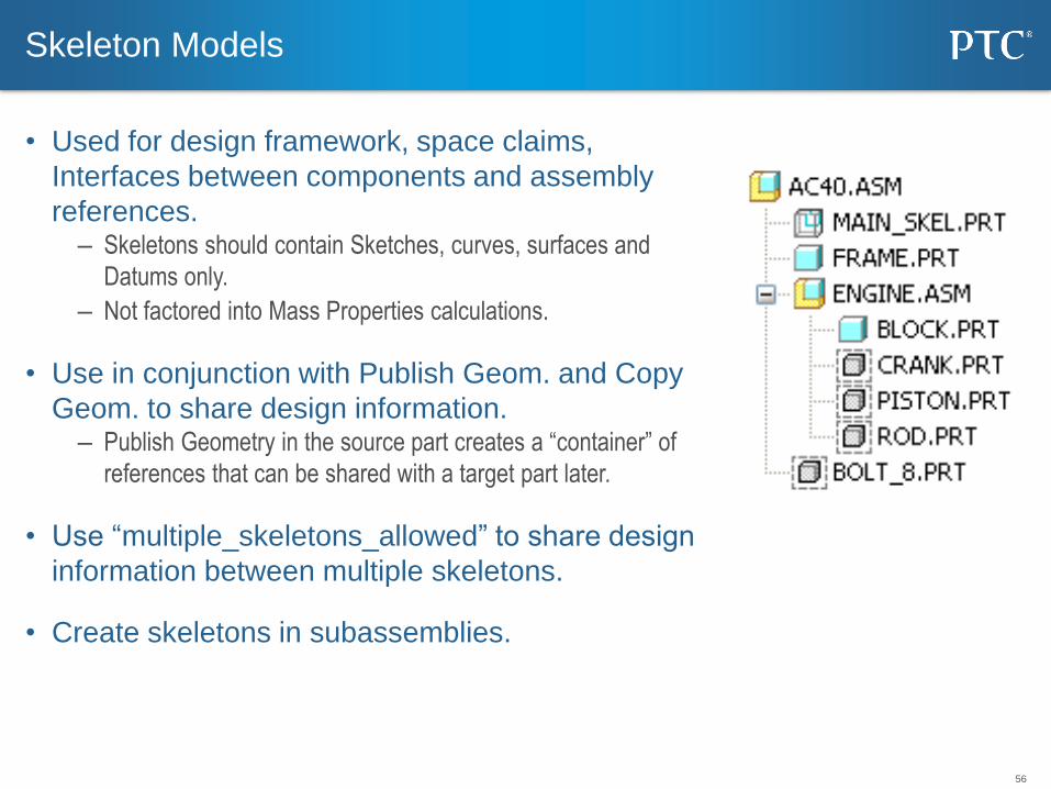
• Used for design framework, space claims,
Interfaces between components and assembly
references. – Skeletons should contain Sketches, curves, surfaces and
Datums only.
– Not factored into Mass Properties calculations.
• Use in conjunction with Publish Geom. and Copy
Geom. to share design information. – Publish Geometry in the source part creates a “container” of
references that can be shared with a target part later.
• Use “multiple_skeletons_allowed” to share design
information between multiple skeletons.
• Create skeletons in subassemblies.
Skeleton Models
57
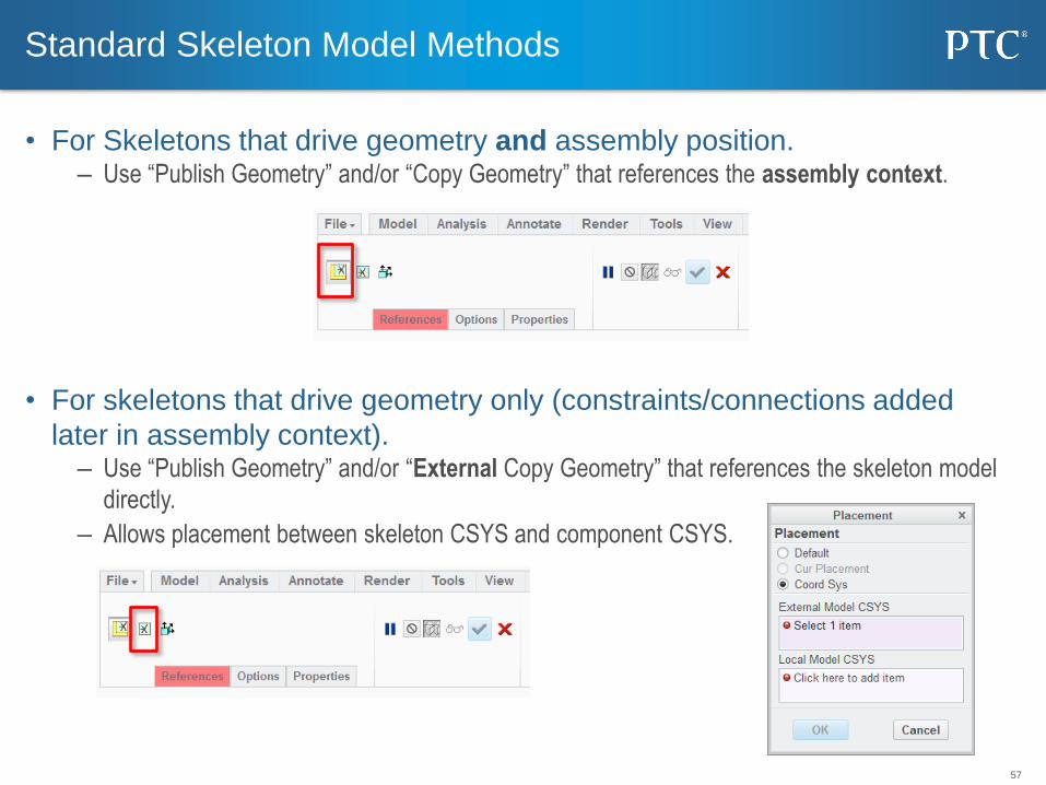
• For Skeletons that drive geometry and assembly position. – Use “Publish Geometry” and/or “Copy Geometry” that references the assembly context.
• For skeletons that drive geometry only (constraints/connections added
later in assembly context). – Use “Publish Geometry” and/or “External Copy Geometry” that references the skeleton model
directly.
– Allows placement between skeleton CSYS and component CSYS.
Standard Skeleton Model Methods
58
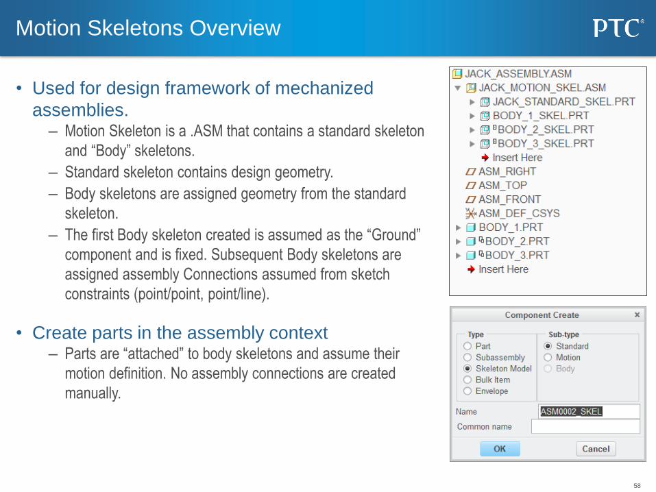
• Used for design framework of mechanized
assemblies. – Motion Skeleton is a .ASM that contains a standard skeleton
and “Body” skeletons.
– Standard skeleton contains design geometry.
– Body skeletons are assigned geometry from the standard
skeleton.
– The first Body skeleton created is assumed as the “Ground”
component and is fixed. Subsequent Body skeletons are
assigned assembly Connections assumed from sketch
constraints (point/point, point/line).
• Create parts in the assembly context – Parts are “attached” to body skeletons and assume their
motion definition. No assembly connections are created
manually.
Motion Skeletons Overview
59
Useful Surfacing Features
60
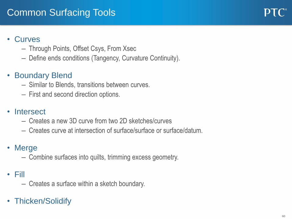
• Curves – Through Points, Offset Csys, From Xsec
– Define ends conditions (Tangency, Curvature Continuity).
• Boundary Blend – Similar to Blends, transitions between curves.
– First and second direction options.
• Intersect – Creates a new 3D curve from two 2D sketches/curves
– Creates curve at intersection of surface/surface or surface/datum.
• Merge – Combine surfaces into quilts, trimming excess geometry.
• Fill – Creates a surface within a sketch boundary.
• Thicken/Solidify
Common Surfacing Tools

61
Using PrecisionLMS for Web-Based-Training
62
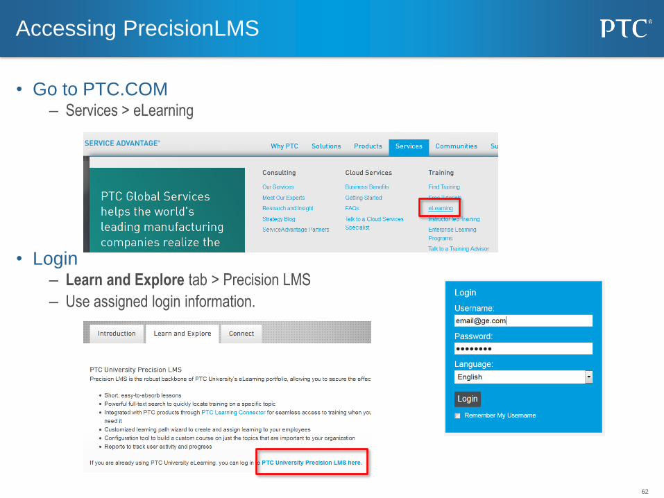
• Go to PTC.COM – Services > eLearning
• Login – Learn and Explore tab > Precision LMS
– Use assigned login information.
Accessing PrecisionLMS