Embed Size (px)
Citation preview

1
John Bultitude, Lonnie Jones, John McConnell, Galen Miller, Jim Magee, Allen Templeton, Abhijit Gurav and Reggie Phillips
KEMET Electronics Corporation 2835 Kemet Way Simpsonville, SC 29681 USA
A Comparison Between Solders & Transient Liquid Phase Sintered Interconnects in High Temperature Multi-Layer Ceramic Capacitors

2
Outline
• Introduction– High Temperature Electronics Trends
• High Temperature Capacitor Types– 200oC ratings– Compare Class I and II stacks
• Solder Interconnect Materials– Shear Stress & Temperature Cycling Robustness
• Alternative Interconnect Materials– Cost effective for MLCC, Pb-free with high temperature capability
• Transient Liquid Phase Sintering (TLPS) Development– CuSn & InAg systems
• Leadless Packaging• Summary• Future Work

3
High Temperature Electronics Trends
Deeper Downhole Wells• Shell Oil Cheap & Deep [1]
WBG Semiconductors• Improve Power Conversion Efficiency [3]
Power Conversion
Si BasedWBG Based on GaN
or SiCDC to DC 85% 95%AC to DC 85% 90%DC to AC 96% 99%
• Higher Junction Temperatures, Switching Frequencies & Voltages
• Future Power Electronics [4]
• Ultra High Pressure High Temperature [2]

4
High Temperature Electronics Trends
• WBG for Power Efficiency – Mainstream High Temp Electronics
• Ultra High Pressure High Temperature Wells in Downhole
• WBG for Power Efficiency – Mainstream High Temp Electronics
• Ultra High Pressure High Temperature Wells in Downhole

5
High Temperature Capacitor Types
• 200oC Catalog Offerings [6]• Voltage Rating @ 200oC• MLCC for ≥ 100VDC
• MLCC Nameplate Capacitance 1Vac, 1kHz, 25oC– Class II X-type Vs. Class I C0G Stacked MLCC
• 200oC Catalog Offerings [6]• Voltage Rating @ 200oC• MLCC for ≥ 100VDC
• MLCC Nameplate Capacitance 1Vac, 1kHz, 25oC– Class II X-type Vs. Class I C0G Stacked MLCC
Capacitor Type 10VDC 100VDC 1000VDCWet Tantalum 1000µF Not Available Not AvailableSolid Tantalum 33µF Not Available Not AvailableSilicon Capacitor 3.3µF Not Available Not AvailableStacked MLCC 340µF 120µF 2.8µFLeaded MLCC 10µF 10µF 2.2µFSurface Mount MLCC 18µF 12µF 0.22µF

6
High Temperature Capacitor TypesClass II X-Type Vs. Class I Ni BME C0G Stacks
KEMET Class I Ni BME C0G
0.15µF 500VDC
Competitor Class II X-Type
0.27µF 500VDC
• At 500VDC capacitance is the same at 25oC• Class II has 30% Lower capacitance at 200oC• At 500VDC capacitance is the same at 25oC• Class II has 30% Lower capacitance at 200oC

7
High Temperature Capacitor TypesClass II X-Type Vs. Class I Ni BME C0G Stacks
Power DissipationP = I 2 R
Where P = Power Dissipated (W)I = Current Applied (ARMS)R = ESR (Ω)
Dielectric Stack Rating Frequency 10kHz 50kHz 100kHz 200kHz 500kHz
ESR 740 mΩ 190 mΩ 110 mΩ 60 mΩ 30 mΩPower
Dissipation @ 3Arms
6.66 W 1.71 W 0.99 W 0.54 W 0.27 W
ESR <10 mΩ <2 mΩ ~1 mΩ <1 mΩ ~2 mΩPower
Dissipation @ 3Arms
0.09 W 0.018 W 0.009 W 0.009 W 0.018 W
ESR/Power Dissipation vs Frequency
Class II X-type
0.27µF 500V
Class I C0G Ni BME
0.15µF 500V

8
Solder Interconnect MaterialsMax Shear Stress & MPt. Capability of Common Solders [7]
• Low Shear of Pb-free solder ≥ 200oC
• HMP Pb-solders used > 200oC
• Low Shear of Pb-free solder ≥ 200oC
• HMP Pb-solders used > 200oC
SolderMelting Temp,
oC80% of Melting
Temp, oC10Sn/88Pb/2Ag 290 23293.5Pb/5Sn/1.5Ag 305 24491.5Sn/8.5Sb 240 192
SAC 305 95.5Sn/3Cu/0.5Ag
217 174

9
Solder Interconnect MaterialsAccelerated Temperature Cycling 10Sn/88Pb/2Ag solder interconnects
• Solder Fatigue causes peripheral lead detachment reducing shear stress capability
• Solder Fatigue causes peripheral lead detachment reducing shear stress capability

10
Solder Interconnect MaterialsStack with 10Sn/88Pb/2Ag solder interconnects
MCC CapacitanceRated Voltage
Length (inch)
Width (inch)
Height (inch)
Temp. Cycling
Life Test @ 200oC 1000hrs
1.5µF 100V 0.25 0.25 0.61 0/12 0/2975nF 1000V 0.25 0.25 0.61 0/12 0/361.7µF 200V 0.40 0.40 0.61 0/12 0/350.27µF 1000V 0.40 0.40 0.61 0/12 0/241.8µF 500V 0.45 1.01 0.61 0/12 0/891.2µF 630V 0.45 1.01 0.61 0/12 0/350.72uF 1000V 0.45 1.01 0.61 0/12 0/360.18uF 2000V 0.45 1.01 0.61 0/12 0/30
5
4
3
• 314,000 life test hours (35.8 years) at 200oC No Failures …..but
• > 85% Pb-Solders face withdrawal from exemption by EU RoHS 2 by 2021 and are already prohibited from Automotive & Commercial Applications
• 314,000 life test hours (35.8 years) at 200oC No Failures …..but
• > 85% Pb-Solders face withdrawal from exemption by EU RoHS 2 by 2021 and are already prohibited from Automotive & Commercial Applications
11
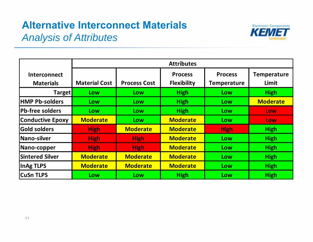
Alternative Interconnect MaterialsAnalysis of Attributes
Material Cost Process CostProcess Flexibility
Process Temperature
Temperature Limit
Target Low Low High Low HighHMP Pb‐solders Low Low High Low ModeratePb‐free solders Low Low High Low LowConductive Epoxy Moderate Low Moderate Low LowGold solders High Moderate Moderate High HighNano‐silver High High Moderate Low HighNano‐copper High High Moderate Low HighSintered Silver Moderate Moderate Moderate Low HighInAg TLPS Moderate Moderate Moderate Low HighCuSn TLPS Low Low High Low High
Attributes
Interconnect Materials

12
Alternative Interconnect MaterialsShear Stress CuSn TLPS, Sintered Ag & 10Sn/88Pb/10Ag Solder
• Sintered Silver bond has low shear high elongation like an adhesive
• CuSn TLPS has similar behavior to solder
• Sintered Silver bond has low shear high elongation like an adhesive
• CuSn TLPS has similar behavior to solder
13
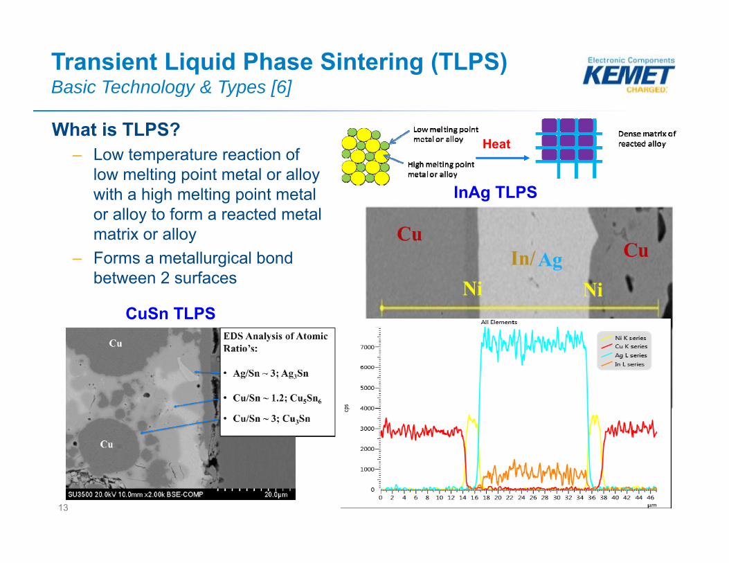
What is TLPS? – Low temperature reaction of
low melting point metal or alloy with a high melting point metal or alloy to form a reacted metal matrix or alloy
– Forms a metallurgical bond between 2 surfaces
Transient Liquid Phase Sintering (TLPS)Basic Technology & Types [6]
CuSn TLPS
Heat
InAg TLPS

14
Single Metal Paste Diffusion (SMPD) Process In-Ag [6]
Ag Lead
Ag MLCC
Indium Paste
Initial Bond Formation• Low Pressure• 250-350oC/30seconds• N2 atmosphere
Ag Lead
Ag MLCCIn
Ag
AgInAg
Diffusion• 200-300oC• N2 atmosphere
Low Ag 500X
High Ag 1000X
Low Ag 500X 48hrs 200oC
High Ag 1000X 120hrs 200oC

15
Transient Liquid Phase Sintering (TLPS)Shear Energy Vs. Temperature [11]
• TLPS has higher shear energy at 200oC that is retained ≥ 250oC• TLPS has higher shear energy at 200oC that is retained ≥ 250oC

16
Transient Liquid Phase Sintering (TLPS)Temperature Cycling of Leaded Stacks
In-Ag TLPS Bonded Case Size 2220 Ni BME C0G on J-Lead [11]
250 500 750 1000Ag over Cu plate 0/30 0/30 0/30 0/30Ag over Ni plate 0/30 0/30 0/30 0/30
MLCC Termination # Temperature Cycles ‐40 to +200oC
TLPS Bonded Case Size 1812 (12) Ni BME X7R 40µF 25V 175oC stack
Lead Frame Chip Finish CuSn InAg Chip Finish 10/88/2Tin 3/6
Copper 4/4GoldSilver 4/4 4/4Tin 0/4
Copper 0/4Gold 0/4Silver 0/4 0/6
Interconnect TLPS Solder
Phosphor Bronze
Alloy 42
high‐Pb hot solder dip
0/6
Temperature Cycling -55 to 200oC
CTE = 17.8 PPM/oC
CTE = 4.5 PPM/oC
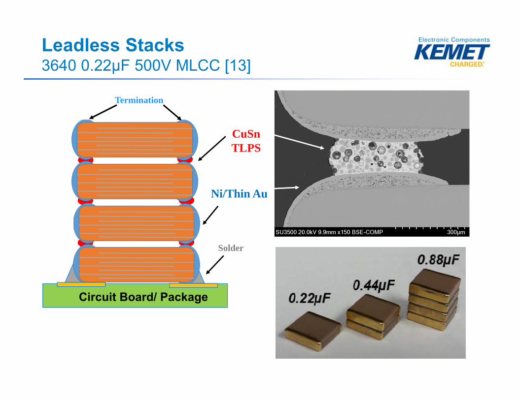
Leadless Stacks3640 0.22µF 500V MLCC [13]
CuSnTLPS
Termination
Circuit Board/ Package
Solder
Ni/Thin Au

Leadless StacksBoard Flexure
10987654321
90
80
7060
50
40
30
20
10
Board Flexure, mm
Perc
ent
3
MLCC2 Chip4 Chip
Variable
Board Flexure
3640 MLCC and 2 and 4 Chip Leadless StacksWeibull
Tested Pieces to 10mm DID NOT FAIL
• Leadless Board Flexure similar to MLCC• Leadless Board Flexure similar to MLCC

1000 hrs storage @ 200C1000 Temp. Cycles -55 to 150CInitial
60
50
40
30
20
10
0
Sample (n=10)
Shea
r Str
ess
(MPa
)
38.939.8
35.8
Shear Stress @ 25C of 3640 2 Chip 3640 Leadless Stacks
Leadless StacksShear Stress @ 25oC
• 19.1MPa failure at 27.9kg > 15 x Higher than 1.8kg minimum AEC Q200 • 19.1MPa failure at 27.9kg > 15 x Higher than 1.8kg minimum AEC Q200

Summary
• Deeper Wells need higher temperature electronics• WBG semiconductors (SiC) need high temperature capacitors• Leaded and stacked MLCC have the highest capacitance values
available rated with 200oC ≥ 100VDC. • Class I Ni BME C0G at 500VDC can have higher capacitance at
200oC and low power dissipation over a broad frequency range• HMP Pb-solders interconnects currently used are reliable but are
disallowed in some applications with future withdrawal of EU RoHS 2 exemptions under consideration
• TLPS materials of CuSn and InAg are viable alternatives to HMP Pb-solders
• Leadless Stacks, a new form factor, have been developed using TLPS materials

Future Work
• TLPS technology scale-up to– Replace Pb-solders in MLCC interconnects– Leadless Stacks form factors
• Capacitor solutions for mainstream high temperature electronics ≥ 150oC
Thank You!


![Laser Sintering of Dip-Based All-Copper Interconnects · method (Table 1) [4]. Intrinsiq IMC4106 could be sintered in a thermal oven at 230 °C without formic acid application, reporting](https://img.pdfslide.us/doc/110x75/5fb3bd7698e6b45bff25b80c/laser-sintering-of-dip-based-all-copper-interconnects-method-table-1-4-intrinsiq.jpg)