Embed Size (px)
Citation preview


Industrial Motion Control, L.L.C. • www.camcoindex.com • (847) 459-5200 1
Table of Contents
Table of Contents
Introduction
A. Engineering
B. RDM Index Drives
C. RD and Intermittor Index Drives
D. Roller Gear Index Drives
E. Parallel Index Drives
F. Right Angle Index Drives
G. Heavy Duty E-Series Index Drives
H. Overload Clutches
I. Parts Handlers
I-2 RPP Cambot® Rotary Parts Handlers
I-15 HD-LPP Heavy Duty Linear Parts Handlers
I-27 MR-LPP Mid-Range Linear Parts Handlers
I-39 WBD Walking Beam Drives
J. Precision Link Conveyors
K. Servo-Mechanical Drives
L. Accessories
M. Torq/Gard Overload Clutches
N. Custom Applications

Industrial Motion Control, L.L.C. • www.camcoindex.com • (847) 459-52002
Quality Policy
Industrial Motion Control, LLC designs and builds motion control components for integrators and users ofautomation equipment.
Our objective is to serve this industry by providing the best value in products and services to our customers.
To accomplish this, Industrial Motion Control, LLC is committed to continual improvement in our overall business performance.
Quality Policy

Industrial Motion Control, L.L.C. • www.camcoindex.com • (847) 459-5200 3
Introduction
Introduction
Industrial Motion Control, LLC (IMC), headquartered in Wheeling, IL USA, is a leadingmanufacturer of precision cam-actuated index drives, parts handlers, in-line conveyors andcustom cams.
IMC HeadquartersWheeling, Illinois USA
European Headquarters (Ferguson S.A.)Braine-le-Château, Belgium
Formed by the merger of Commercial CamCo. and Ferguson Machine Co., IMC offersthe widest range of products in the industry.With over 100 years of experience and significant investments in personnel and
capital equipment, IMC is unique in its abilityto manufacture a full range of motion controlproducts under the Ferguson and Camcobrands.

Industrial Motion Control, L.L.C. • www.camcoindex.com • (847) 459-52004
Introduction
MANUFACTURING FACILITYSALES OFFICE
Introduction (continued)
IMC serves designers, builders and users of specialty automation equipment worldwide with manufacturing facilities in both North American and Europe. Sales offices are in North & South America, Asia and Europe.
IMC HeadquartersIndustrial Motion Control, LLC1444 South Wolf RoadWheeling, IL 60090 USATel: 847-459-5200Fax: 847-465-3042E-Mail: [email protected]
IMC Michigan550 Forest AvenueUnit #14Plymouth, MI 48170Tel: 734-459-8080Fax: 734-459-8110
European HeadquartersEuropean HeadquartersFerguson Co. SA33 Parc IndustrielB-1440 Braine-le-ChâteauBelgiumTel: +32 (0)2 367-1311Fax: +32 (0)2 [email protected]
Camco UK Ltd.432 Perth AvenueSlough Trading EstatesSlough, Berkshire SL1 4TSUnited KingdomTel: +44 (0)1753-786-100Fax: +44 (0)1753-786-101

Industrial Motion Control, L.L.C. • www.camcoindex.com • (847) 459-5200 5
Introduction
IMC has a full staff of technically trained sales engineers and applications engineers to helpselect and specify the appropriate components for each specific machine design application.Proprietary software ensures that components are selected to meet the customers’ require-ments for accuracy, speed, load capacity and life expectancy.
Introduction (continued)
Industrial Motion Control, L.L.C. • www.camcoindex.com • (847) 459-52006
Introduction
Solutions in Motion™
Introduction (continued)
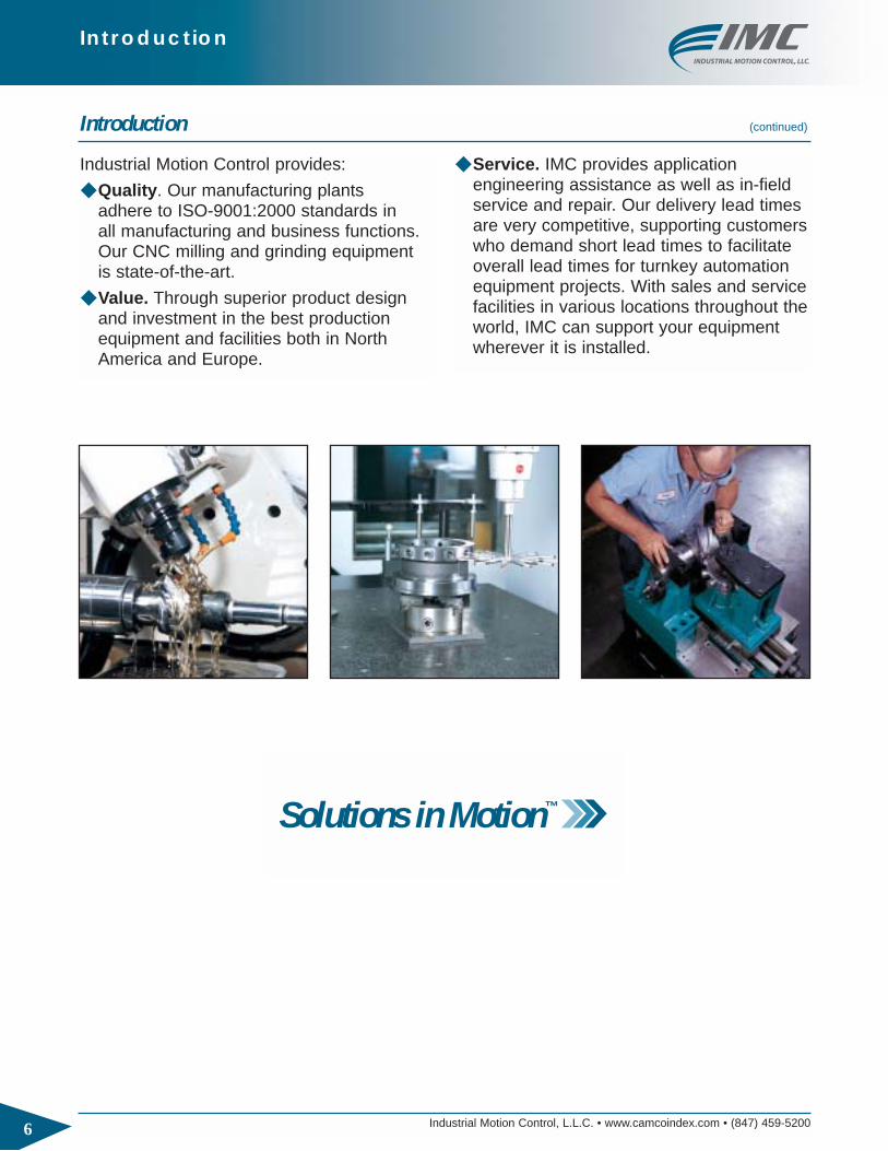
Industrial Motion Control provides:
◆ Quality. Our manufacturing plants adhere to ISO-9001:2000 standards in all manufacturing and business functions.Our CNC milling and grinding equipment is state-of-the-art.
◆ Value. Through superior product designand investment in the best productionequipment and facilities both in NorthAmerica and Europe.
◆ Service. IMC provides application engineering assistance as well as in-fieldservice and repair. Our delivery lead timesare very competitive, supporting customerswho demand short lead times to facilitateoverall lead times for turnkey automationequipment projects. With sales and servicefacilities in various locations throughout theworld, IMC can support your equipmentwherever it is installed.


Engineering
A
A-2 Industrial Motion Control, L.L.C. • www.camcoindex.com • (847) 459-5200
Foreword
Cam-actuated motion control is a specializedbusiness. In a 4 to 5-year university curriculum formechanical engineering, most students spend only a few weeks studying cams and their related mechanisms. In addition to continuing academicresearch, many advances in cam technology havebeen made by companies and employees involved in the commercial application of these products. This engineering section provides the basic concepts necessary for machine designers to wisely choose the best cam solutions for their application.
There are some good publications available to thegeneral public for those seeking a more in-depthunderstanding of the subject. Three that we can
recommend are Clyde H. Moon’s “Cam DesignManual for Engineers, Designers, and Draftsmen”,published by Emerson Electric Co., Harold A.Rothbart’s book, “Cam Design Handbook” publishedby McGraw-Hill and Robert L. Norton’s book “CamDesign and Manufacturing Handbook” published byIndustrial Press. Mr. Moon’s book is available in AdobeAcrobat® PDF format on the IMC web site and can beeasily downloaded at www.camcoindex.com.
We would like to thank all of the IMC employees and IMC manufacturer representatives that have contributed to our extensive cam knowledge base and helped collect the information presented in thiscatalog.
Introduction
Industrial Motion Control, LLC is a joint-venture company formed in 2001 between Ferguson MachineCo. and Commercial Cam Co., also known as Camco.
Ferguson has been in continuous operation since1930, with European operations established in 1961.Camco was established in 1939, first manufacturingthe copper coils required for the then-emerging residential and commercial air-conditioning and refrigeration industries. Camco needed cam-actuated machinery to produce these products andeventually the business focused on the commercial-ization of cam-operated machinery, index drives and custom cams.
As divisions of larger, Fortune 500 companies, both Ferguson and Camco were able to invest in substantial amounts of equipment and facilities whiledeveloping a diverse line of products that includeindex drives, custom cams, parts handlers, precision-link conveyors and servo-motor drive systems.
Today, as IMC, Ferguson and Camco are the world’slargest producer of cam-actuated index drives, utilizingstate-of-the-art production equipment to provide thehighest quality cam-actuated and servo motor-actuated motion control products available.
Solutions in Motion™
Choosing the proper type and size of index drive canbe complicated. Over the years, IMC has developed a wealth of experience in selecting and applying theoptimum product solutions to a wide variety of applica-tions. IMC application engineers, sales engineers,
catalog information and proprietary software all combine to make the task less daunting. This engineering section will help eliminate much of themystery behind high-performance indexing and itsapplication in specialty machinery design.
Adobe Acrobat® is a registered trademark of Adobe Systems, Inc.

Engineering
A
A-3Industrial Motion Control, L.L.C. • www.camcoindex.com • (847) 459-5200
What is Indexing?
Indexing can be linear or rotary. As defined by IMC, indexing is the process of starting and stopping in preciseintervals at precise locations.
Why Cam-Actuated Index Drives?
The advantages of cam-controlled motion are obviousand effectively demonstrated in everyday life by thecamshaft found in automobile engines. No othertechnology can provide comparable speed, precision, repeatability, load capability and reliability.
Cam-driven mechanisms require little or no maintenance and are capable of moving, with precision, a wide variety of products and components.For example – larger E-Series Index Drives rotateseveral tons of automotive body parts in seconds –and smaller P-Series and RG-Series index drives accurately index pharmaceutical components and electronic components in milliseconds. Themechanical technology typically requires no maintenance, other than routine checks for properlubrication. Rolling pre-loaded contact between thecams and cam followers minimize wear and thermalinefficiencies. This preloading technique is also usedon the input and output bearings of the index drive,achieving the most rigid, accurate and efficientmechanical actuator possible. With this inherent
rigidity, settling time (the time to dampen any vibrations) in dwell is short or virtually non-existent —very important for many applications requiring acombination of speed and precise positioning.
Through careful design of the cam profile, velocity andacceleration are also controlled throughout the index-ing cycle, minimizing vibration and providing a known,repeatable displacement-time relationship.
In summary, cam-operated indexing systems have thefollowing features and benefits:
◆ Controlled Acceleration and Decelerations
◆ Repeatable, Accurate Positioning
◆ High Load Capacity
◆ High Speed Capability
◆ Smooth Motion
◆ Quick Settling Time in the Dwell Position
◆ Low Maintenance, Superior Life
◆ Known Displacement-Time Relationship
◆ Known Power Requirement
INDEX DWELL
DISPLACEMENT
TIME
INDEX DWELL
VELOCITY
Linear Indexing
Rotary Indexing

Engineering
A
A-4 Industrial Motion Control, L.L.C. • www.camcoindex.com • (847) 459-5200
Types of Motions
Controlled Indexing is comprised of three sections orphases: acceleration, peak velocity and decelera-tion. To optimize the transition from one phase to the next, several standard motion profiles have beendeveloped. They include Cycloidal, Modified Sineand Modified Trapezoidal. In special circumstances,the motion required calls out for certain positionsand/or velocities at certain times in the index cycle.Special Polynomial curves can be constructed forthese applications. In other applications, the peakvelocity needs to match the velocity
of another component of the machine – and variationsof Polynomial and Modified Sine curves can be customized to suit the requirements.
IMC usually employs Modified Sine curves due to their smooth transition from peak acceleration todeceleration and smooth power demand curves.Frequently, a period of peak, constant velocity isneeded due to cam design or machine design require-ments and a variation of this motion curve, ModifiedSine Constant Velocity (abbreviated “msc”), is used.
In addition to those motions already described, IMCalso has several other special application motions.They include Modified Sine Quick Return (MSQR)and Synthesized Modified Sine Harmonic (SMSH).MSQR is an oscillating motion with no dwells. It has a forward stroke with a matched peak velocity and a quick return stroke. It is used in applications wherea constant speed conveyor or rotating dial is tracked(velocity is synchronized) in order to perform work
during the synchronized movement. Examples areprinting or moving a saw or cutting blade to cut parts to size. SMSH is a motion used in oscillating applications that require a dwell at one end of thestroke and no dwell at the other. This motion reducesthe number of acceleration reversals. Please contactyour local IMC sales representative or IMC applicationengineer for further details.
-10.0
-8.0
-6.0
-4.0
-2.0
0.0
2.0
4.0
6.0
8.0
10.0
0 30 60 90 120
Modified Sine Modified Trapezoid Cycloidal
ACCELERATION COMPARISON
-10.0
-8.0
-6.0
-4.0
-2.0
0.0
2.0
4.0
6.0
8.0
10.0
0 30 60 90 120
POWER DEMAND COMPARISON
Modified Sine Modified Trapezoid Cycloidal
-3
-2
-1
0
1
2
3
60 120 180
-6
-4
-2
0
2
4
6
Displacement Velocity Acceleration
Synthesized Modified-Sine Harmonic (SMSH) Motion
0 360240 300

Engineering
A
A-5Industrial Motion Control, L.L.C. • www.camcoindex.com • (847) 459-5200
Types of Index Drives
Roller Gear
Right Angle
This family of indexers uses a globoidal cam in conjunction with followers mounted radially outwardfrom the circumference of the follower wheel, muchlike the teeth of a gear. The input shaft is
This family of indexers uses a cylindrical or barrel camin conjunction with followers mounted parallel to theaxis of the output. Similar to the Roller Gear, the inputshaft is perpendicular to the output shaft. The cam istucked partially underneath the output wheel, offeringa more compact arrangement. For a given torquerequirement, Right Angle indexers usually occupy theleast amount of floor space and volume. IMC production equipment allows us to produce very largeindex drives in this geometry. Control of the cam ribthickness allows for preloading. Center distancesbetween input shaft and output shaft can be fixedaccurately. The minimum cam rib requirements limitthe range of motions (output motions as a function of
input motion) when compared to Roller Gear indexers.In summary, Right Angle Indexers provide:
◆ Most Compact Design for Given Output Capacity
◆ Fixed Center Distance Between Output and Input Shafts (tighter tolerance on the distance between input and output shafts)
◆ Flanged Output Capability for Dial Mounting Applications (E-Series & RAD Series)
◆ Through-Hole Capability (E-Series & RAD series)
◆ 3 to 24 Stop Range
◆ Very Large Index Drives for Automotive Assembly and Large (up to 40 feet) Dial Diameters
perpendicular to the output shaft. With this right angleconfiguration, it is possible to provide an optional largethrough-hole along the axis of the output shaft, ordesign a large output flange to accept dials (dialmounting). Large cam diameters relative to the outputfollower wheel allow for a wide rande of specialmotions, short motion periods and a large output displacement for relatively smaller input displacement.In summary, Roller Gear Indexers provide:
◆ Compact Low Profile Design
◆ Flanged Output Capability for Dial Mounting Applications
◆ Through-Hole Capability (for electric and pneumatic lines or stationary center post)
◆ Motion Flexibility (special and complex motions) due to relatively large cam
◆ 2 to 24 Stop Range
IMC manufactures all three types of index drive geometries: Roller Gear, Right Angle, and Parallel.

Engineering
A
A-6 Industrial Motion Control, L.L.C. • www.camcoindex.com • (847) 459-5200
Types of Index Drives (continued)
Parallel
This family of indexers use a pair of conjugate platecams with yoke-mounted followers mounted parallelto the axis of the output. The input shaft is parallel tothe output shaft. With this parallel configuration, thereare no ribs on the cam as found on Roller Gear andRight Angle indexers. Also unique to the Parallel family is no reversal of the cam followers. Since theyrotate in the same direction throughout the indexcycle, index rates of over 1000 indexes per minute are possible. Without minimum rib requirements (no rib),larger followers can be used, providing high torquecapability. Parallel indexers produce high outputdisplacements for relatively smaller input
displacements. The yoke-mounted geometry alsomakes the Parallel family more resistant to shockloading (more robust). Double output shafts are alsoavailable. In summary, Parallel Indexers provide:
◆ High Speed Capability (with Non-ReversingFollowers)
◆ High Load Capability (with Oversized Followers)
◆ Shock Resistance (More Robust)
◆ Motion Flexibility (special and complex motions) dueto conjugate cam geometry
◆ 1 to 8 Stop Range
Model Code Designation
Camco Model Code Designation
For Indexers Only
663RAD 6 H36-180
ModelIndexPeriod
Cam Followerdiameter in32nds of an inch(H36 = 1.125")
Number of Stops
Ferguson Model Code Designation
For Indexers Only
FD162F 8/2 F100-90
Number of Stops(8/2 = 4 stops)
Model
Cam Followerdiameter in100ths of an inch(F100 = 1")
Index Period

Engineering
A
A-7Industrial Motion Control, L.L.C. • www.camcoindex.com • (847) 459-5200
Approach to Sizing Index Drives
Within each family type (Roller Gear, Right Angle,Parallel), IMC offers more than a dozen different sizesof index drives. The first consideration when choosingan index drive type is mounting requirements and thegeometry of the driven member. The mountingrequirements usually determine the type of indexerand then size is selected. Often the geometry (size of dial, for example) helps determine the initial choice.The index drive size is verified through data sheet calculations.
All IMC indexers are designed and rated to have a B10
life of 8,000 hours on the followers and over 100,000hours on the other major components. The B10 life isan estimate of time between cam follower replace-ment. For example, a B10 life estimate of 15,000 hoursmeans that we can expect 10% of the followers tobegin to show wear after 15,000 hours of operation.For this case, IMC would recommend replacing all ofthe followers after 15,000 hours of continuous operation.
Many helpful software programs have been developedby IMC to assist with the selection process. The following examples will show both a manual method of calculating and a faster method using special software.
All sizing for rotating equipment (motors, gear reducers and indexers) rely on the basic NewtonianMechanics equation:
Torque = Ti = I α
Where I is the Rotational Mass Moment of Inertia andα is the peak angular acceleration (radians/sec2).
Additional work or friction torque is also added, givingthe full equation:
TTotal = I α + Tw
Where Tw = Work Torque = µ x R x F
µ = coefficient of friction, R = radius to Work Forceand F = Force
For smaller diameter dial applications, Work Torque isnegligible. For larger diameter dial applications, WorkTorque can be significant. The inefficiencies of speedreducers also add to the total Work Torque.
After Torque is calculated we then determine thepower requirements through:
Power = T x ω = I x α x ω
Where ωω is the rotational velocity (radians/sec). Notethat with an indexing application, αα and ωω are a function of time or αα = f(t) and ωω = f(t).
Since I is usually constant, power peaks when theproduct of αα and ωω peak. Software automaticallychooses this peak product, and the manual data sheetmethods rely on Ki and Kf factors to determine peakpower. Ki and Kf are explained later in thisEngineering catalog section.
Input (camshaft) torque requirements are calculatedthrough the conservation of energy equation, Power in = Power out, or:
Tin x ωin = Tout x ωout
Restated, Tin = Tcamshaft = Tc = Tout x ωout / ωin
Note that:Ki ≡ ωout / ωin at peak value of theproduct of αout x ωout so we have:
Tc(inertia) = Tinertia out x Ki (for inertia)
Similarly,
Tc (work) = (Twork out + Tfriction out) x Kf
(for friction and work torque)
Where Kf ≡ ωout / ωin at ωout (maximum).
Total Camshaft Torque
Tc = Tc(inertia) + Tc(work)
Horsepower is calculated based on Camshaft Torqueand Speed
Power = HP = (Horsepower)
Where N = Camshaft speed in RPM
E = Efficiency of the gear reducer
Tc is in units of in-lbs.
Tc x N
63025 x E
Engineering
A
A-8 Industrial Motion Control, L.L.C. • www.camcoindex.com • (847) 459-5200
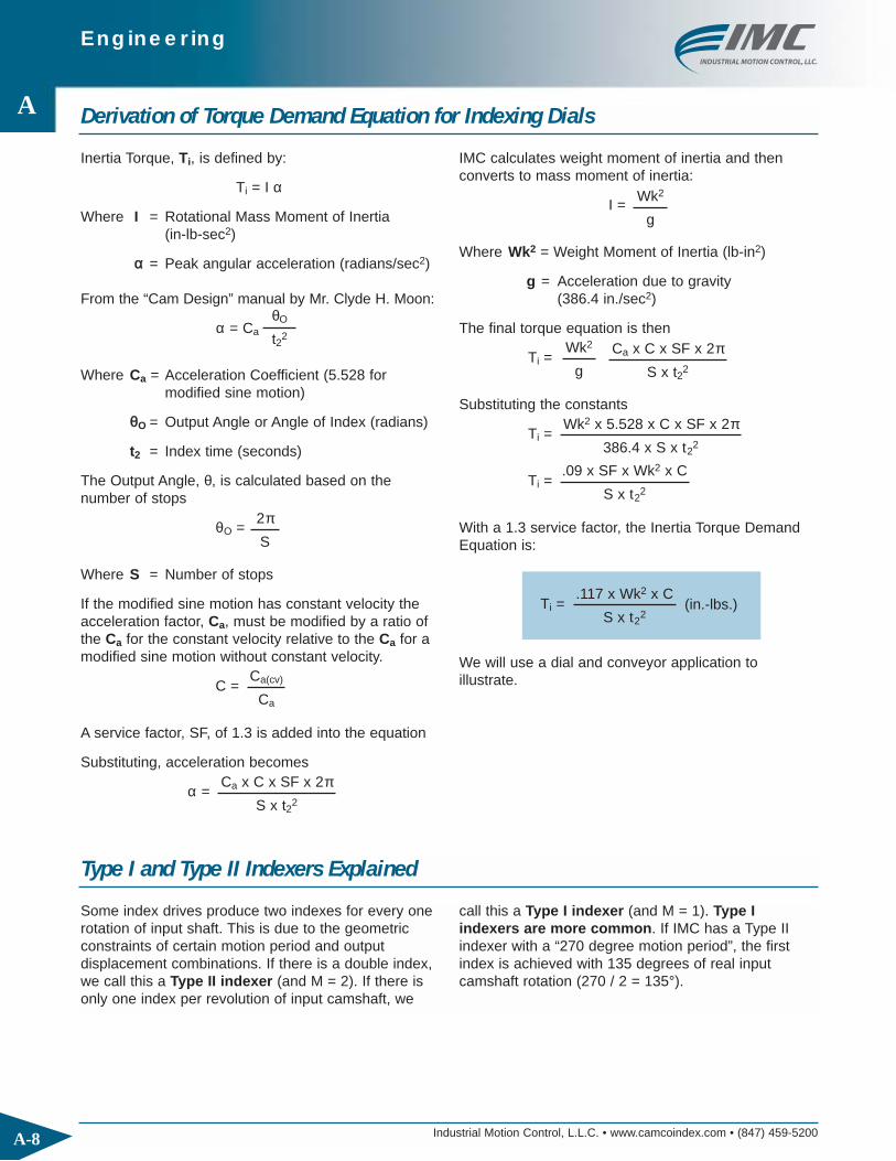
Derivation of Torque Demand Equation for Indexing Dials
Inertia Torque, Ti, is defined by:
Ti = I α
Where I = Rotational Mass Moment of Inertia (in-lb-sec2)
αα = Peak angular acceleration (radians/sec2)
From the “Cam Design” manual by Mr. Clyde H. Moon:
α = Ca
Where Ca = Acceleration Coefficient (5.528 formodified sine motion)
θθO = Output Angle or Angle of Index (radians)
t2 = Index time (seconds)
The Output Angle, θ, is calculated based on the number of stops
θO =
Where S = Number of stops
If the modified sine motion has constant velocity theacceleration factor, Ca, must be modified by a ratio ofthe Ca for the constant velocity relative to the Ca for amodified sine motion without constant velocity.
C =
A service factor, SF, of 1.3 is added into the equation
Substituting, acceleration becomes
α =
IMC calculates weight moment of inertia and then converts to mass moment of inertia:
I =
Where Wk2 = Weight Moment of Inertia (lb-in2)
g = Acceleration due to gravity(386.4 in./sec2)
The final torque equation is then
Ti =
Substituting the constants
Ti =
Ti =
With a 1.3 service factor, the Inertia Torque DemandEquation is:
Ti =
We will use a dial and conveyor application to illustrate.
θO
t22
2πS
Ca(cv)
Ca
Ca x C x SF x 2πS x t22
Wk2
g
Wk2
g
Ca x C x SF x 2πS x t22
Wk2 x 5.528 x C x SF x 2π386.4 x S x t2
2
.09 x SF x Wk2 x C
S x t22
.117 x Wk2 x C
S x t22
(in.-lbs.)
Type I and Type II Indexers Explained
Some index drives produce two indexes for every onerotation of input shaft. This is due to the geometricconstraints of certain motion period and output displacement combinations. If there is a double index,we call this a Type II indexer (and M = 2). If there isonly one index per revolution of input camshaft, we
call this a Type I indexer (and M = 1). Type I indexers are more common. If IMC has a Type IIindexer with a “270 degree motion period”, the firstindex is achieved with 135 degrees of real inputcamshaft rotation (270 / 2 = 135°).
Engineering
A
A-9Industrial Motion Control, L.L.C. • www.camcoindex.com • (847) 459-5200
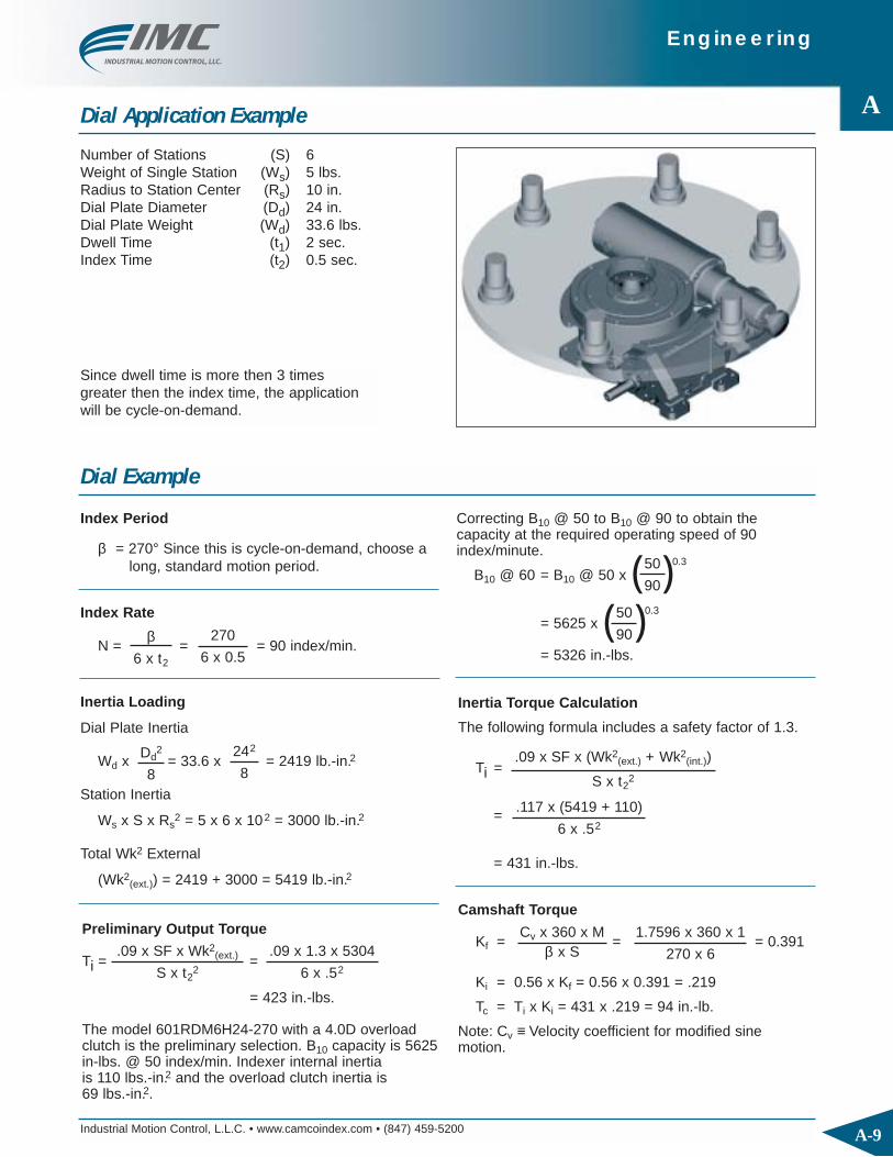
Dial Application Example
Number of Stations (S) 6Weight of Single Station (Ws) 5 lbs.Radius to Station Center (Rs) 10 in.Dial Plate Diameter (Dd) 24 in.Dial Plate Weight (Wd) 33.6 lbs.Dwell Time (t1) 2 sec.Index Time (t2) 0.5 sec.
Dial Example
Index Period
β = 270° Since this is cycle-on-demand, choose along, standard motion period.
Preliminary Output Torque
Ti = =
= 423 in.-lbs.
The model 601RDM6H24-270 with a 4.0D overloadclutch is the preliminary selection. B10 capacity is 5625in-lbs. @ 50 index/min. Indexer internal inertiais 110 lbs.-in.2 and the overload clutch inertia is69 lbs.-in.2.
Index Rate
N = = = 90 index/min.
Inertia Loading
Dial Plate Inertia
Wd x = 33.6 x = 2419 lb.-in.2
Station Inertia
Ws x S x Rs2 = 5 x 6 x 102 = 3000 lb.-in.2
Total Wk2 External
(Wk2(ext.)) = 2419 + 3000 = 5419 lb.-in.2
β6 x t2
270
6 x 0.5
Dd2
8
242
8
.09 x SF x Wk2(ext.)
S x t22
.09 x 1.3 x 5304
6 x .52
Correcting B10 @ 50 to B10 @ 90 to obtain the capacity at the required operating speed of 90index/minute.
B10 @ 60 = B10 @ 50 x
= 5625 x
= 5326 in.-lbs.
( )0.350
90
( )0.350
90
Inertia Torque Calculation
The following formula includes a safety factor of 1.3.
Ti =
=
= 431 in.-lbs.
.09 x SF x (Wk2(ext.) + Wk2
(int.))
S x t22
.117 x (5419 + 110)
6 x .52
Camshaft Torque
Kf = = = 0.391
Ki = 0.56 x Kf = 0.56 x 0.391 = .219
Tc = Ti x Ki = 431 x .219 = 94 in.-lb.
Note: Cv ≡ Velocity coefficient for modified sinemotion.
Cv x 360 x Mβ x S
1.7596 x 360 x 1
270 x 6
Since dwell time is more then 3 times greater then the index time, the applicationwill be cycle-on-demand.

Engineering
A
A-10 Industrial Motion Control, L.L.C. • www.camcoindex.com • (847) 459-5200
Dial Example Using IMC Software
With the advent of user-friendly, Windows-based software, we can input the data and quickly get the results. The program takes into account additional factors such as internal friction and cam stresses for more precisecalculations. Shown below are the input screens and output screens for the same dial application:
Reducer Selection
Assuming an 1800 RPM motor speed, the modelR180 reducer with a 20:1 reduction ratio is selected.
Horsepower
Hp = = = 0.16 Hp
Due to component compatibility and horsepower requirements, a 1/3 horsepower motor is selected for this application.
Tc x Nc
63,025 x E
94 x 90
63,025 x .85
Dial Example (continued)
Camshaft RPM
Nc = = = 90 RPM
Where M=1 for Type 1 indexers (see p. A-14)
β6 x t2 x M
270
6 x .5 x 1
Dial Application Input Screen Dial Application Results Screen
Engineering
A
A-11Industrial Motion Control, L.L.C. • www.camcoindex.com • (847) 459-5200
Conveyor Application Example
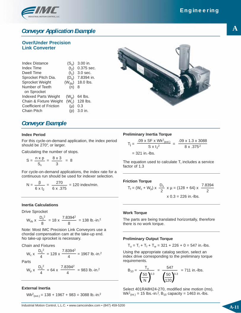
Over/Under Precision Link Converter
Index Distance (Sx) 3.00 in.Index Time (t2) 0.375 sec.Dwell Time (t1) 3.0 sec.Sprocket Pitch Dia. (Ds) 7.8394 in.Sprocket Weight (Wds) 18.0 lbs.Number of Teeth (n) 8
on SprocketIndexed Parts Weight (Wp) 64 lbs.Chain & Fixture Weight (Wc) 128 lbs.Coefficient of Friction (µ) 0.3Chain Pitch (p) 3.0 in.
Index Period
For this cycle-on-demand application, the index periodshould be 270°, or larger.
Calculating the number of stops.
S = = = 8
For cycle-on-demand applications, the index rate for acontinuous run should be used for indexer selection.
N = = = 120 index/min.
Inertia Calculations
Drive Sprocket
Wds x = 18 x = 138 lb.-in.2
Note: Most IMC Precision Link Conveyors use achordal compensation cam at the take-up end.No take-up sprocket is necessary.
Chain and Fixtures
Wc x = 128 x = 1967 lb.-in.2
Parts
Wp x = 64 x = 983 lb.-in.2
External Inertia
Wk2(ext.) = 138 + 1967 + 983 = 3088 lb.-in.2
n x p
Sx
β6 x t2
270
6 x .375
8 x 3
3
Ds2
8
Ds2
4
Ds2
4
7.83942
8
7.83942
4
7.83942
4
Conveyor Example
Preliminary Inertia Torque
Ti = =
= 321 in.-lbs.
The equation used to calculate Ti includes a servicefactor of 1.3
Friction Torque
Tf = (Wc + Wp) x x µ = (128 + 64) x
x 0.3 = 226 in.-lbs.
.09 x SF x Wk2(ext.)
S x t22
.09 x 1.3 x 3088
8 x .3752
Ds
2
7.8394
2
Work Torque
The parts are being translated horizontally, thereforethere is no work torque.
Preliminary Output Torque
To = Ti + Tf + Tw = 321 + 226 + 0 = 547 in.-lbs.
Using the appropriate catalog section, select an index drive corresponding to the preliminary torquerequirements.
B10 = = = 711 in.-lbs.
Select 401RA8H24-270, modified sine motion (ms),Wk2
(int.) = 15 lbs.-in.2, B10 capacity = 1463 in.-lbs.
To
( )0.350
N
547
( )0.350
120

Engineering
A
A-12 Industrial Motion Control, L.L.C. • www.camcoindex.com • (847) 459-5200
Conveyor Example Using IMC Software
As demonstrated for the dial application, we can input the conveyor data into the software program and quicklyget results. Shown below are the input screens and output screens for the conveyor application:
Camshaft Torque
Tc = (Ti x Ki) + (Tf x Kf) + (Tw x Kf)
= (326 x 0.16) + (226 x 0.29) + 0
= 118 in.-lbs.
Camshaft RPM
Nc = = = 120 RPM
This is a type 1 unit, therefore M = 1.For type 2 or 3, M = 2, M = 3.
From the Right Angle Series indexer catalog section,an R225 reducer with a 15:1 reduction ratio is chosen.
Horsepower
Hp = = = 0.30 Hp
Due to component compatibility and horsepowerrequirements, a one horsepower motor is chosen forthis application.
β6 x t2 x M
270
6 x .375 x 1
Tc x Nc
63,025 x E
118 x 120
63,025 x .75
Overload Protection
Output overload protection should be used with this application. A large instantaneous gear ratio at the start of index makes output overload protection the preferred method for protecting the index drive. With an outputoverload clutch, jams or overloads at the start of index can easily be detected prior to damaging the indexer.
From your IMC indexer catalog, select the appropriate clutch model for the index drive being used. Clutch model 2.3FC-SD with Wk2
(cl.) = 31 lbs.-in.2 is chosen.
Conveyor Example (continued)
Inertia Torque
The actual inertia torque including indexer internalinertia and clutch inertia can now be calculated.
Ti =
=
= 326 in.-lbs.
Output Torque
To = Ti + Tf + Tw = 326 + 226 + 0 = 552 in.-lbs.
C, Ki and Kf
Values for C, Ki and Kf can be calculated or found inthe table on page A-19.
C = 1.0, Ki = 0.16, Kf = 0.29
.09 x SF x (Wk2(ext.) + Wk2
(int.) + Wk2(cl.) x C
S x t22
.09 x 1.3 x (3088 + 15 + 31) x 1
8 x .3752
Conveyor Example Input Screen Conveyor Example Results Screen

Engineering
A
A-13Industrial Motion Control, L.L.C. • www.camcoindex.com • (847) 459-5200
Brief Oscillator Example
IMC software can handle a variety of slider-crank, scotch yoke and 4-bar mechanisms.
Slider Crank Linkage Example
Servo-Mechanical ExampleCamco-Ferguson software can also be used to sizeservo-driven indexers such as the Flex-i-Dex andIndexers with constant-lead cams. The followingillustrations show input and output data for a typicalservo-driven application.
Servo Application Input Screen Servo Application Output Screen
Flex-i-Dex Constant Lead Indexer

Engineering
A
A-14 Industrial Motion Control, L.L.C. • www.camcoindex.com • (847) 459-5200
Cycle-On-Demand vs. Continuous Running Applications
If the input shaft (camshaft) of an index drive runscontinuously, the ratio of the index time and stop(dwell) time are fixed and a function of the number ofdegrees on the cam that impart motion to the outputshaft (motion period).
If t1 is the dwell time and t2 is the index time, totaltime tt = t1 + t2
Typically, the motion period of the cam is rarely lessthan 90 degrees, due to the geometry constraints ofcam design. To illustrate, let’s choose a 90 degreeindex period (ββ2), leaving 270 degrees (ββ1) for dwelltime (90° + 270° = 360° total).
Assume 60 RPM camshaft or N = 60.
Thenβtotal = 360° = 6 x N x ttotal or
ttotal = = = 1 sec.
The index time
t2 = = = 0.25 sec.
And dwell time
t1 = = = 0.75 sec.
Note tt = t1 + t2 = .75 + .25 = 1.0 sec.
In this example the ratio of dwell time to index time is.75 sec / .25 sec or 3:1.
Suppose you need more time for dwell, due to themanufacturing process required of the machine.You can then stop the camshaft in dwell for aspecified amount of time, and then re-start thecamshaft. This is known as cycle-on-demand.Example: You want to index in 0.25 seconds, but stayin the dwell position for 10 seconds. By using a brakemotor (or motor with clutch-brake module), you stopthe camshaft and then restart after the required 10seconds. By rotating the camshaft at 60 RPM whenthe motor is engaged, you achieve the desired 0.25index time. These two charts illustrate and summarizethe two concepts:
Continuous Input
Fixed Dwell Time
0.0 0.5 1.0 1.5 2.0 2.5 3.0
Time (seconds)
Output Displacement Camshaft Velocity
Dwell Dwell
Cycle-on-Demand InputVariable or Extended Dwell Time
0.0 0.5 1.0 1.5 2.0 2.5 3.0 3.5 4.0 4.5 5.0
Time (seconds)
Output Displacement Camshaft Velocity
Dwell Dwell
360
6N
360
6 x 60
β2
6N
90
6 x 60
β1
6N
270
6 x 60

Engineering
A
A-15Industrial Motion Control, L.L.C. • www.camcoindex.com • (847) 459-5200
Important Formulas
Torque Due to Inertia
Ti =
Torque Due to Friction (dial application)
Tf = (1/2Wd + Ws) x Rµ x µ
Where Wd = Dial Weight
Ws = Total weight of the stations
Rµµ = the radius where rollers or supportbearing contact the dial plate
µµ = coefficient of friction
Torque Due to Work
Tw = Ww x Rw
Where Ww = work force or work load
Rw = radius at which the force is acting,perpendicular to the axis of rotation
Total Output Torque
Tt = Ti + Tf + Tw
Camshaft Torque
Tc = Ti x Ki + (Tf + Tw) x Kf
Relationship between cam angle, time and RPM:
β = 6 x N x t x M
where β (degrees), N (RPM), t (sec.), M (unitless)
or N = β / (6 x M x t)
Factor for calculating camshaft torque due to inertia at indexer output, for modified sine motions:
Ki = 0.56 Kf
Factor for calculating camshaft torque due to friction and work load at indexer output:
Kf =
A chart of Ki and Kf factors are listed on page A-19.
Motion Velocity Factor for Modified Sine Motion(Moon Velocity Factor)
Cv = if F = 0, Cv = 1.7596
Where F = % of constant velocity, e.g. F = 0.25 for25% constant velocity, F = 0 for pure Modified SineMotion (no constant velocity).
Motion Acceleration Factor (Moon Acceleration Factor)
Ca = if F = 0, Ca = 5.5280
Constant Velocity Load Adjustment Factor
C = or C =
Input Gear Ratio
Gi ≡ Nmotor / Ncamshaft = Nm/Nc
Output Gear Ratio
Go ≡ Ddriver / Ddriven = Dr /Dn
Effective Radius of Gyration
k =
K is the theoretical radius at which all of the weightwould be concentrated to produce an equivalentweight moment of inertia
Speed Correction Factor
Fs =
Horsepower
Hp =
.09 x SF x (Wk2(ext.) + Wk2
(int.) + Wk2(cl.)) x C
S x t22
Cv x 360 x M
β x S
1.7596
1 + (F x 0.7596)
Cv x π
1 - F
Ca
5.5280
1
1 - 0.24F - 0.76F2
∑ Wk2
∑ W
( )0.350
N
Tc x Nc
63025 x E
Refer to page A-16 for Nomenclature

Engineering
A
A-16 Industrial Motion Control, L.L.C. • www.camcoindex.com • (847) 459-5200
Nomenclature
β deg. Index Period
µ – Coefficient of Friction
B10 in.-lbs. Basic Dynamic Capacity of the Indexer at a Defined Index Rate
C – Constant Velocity Load Adjustment Factor
Ca – Motion Acceleration Factor
Cd – Factor for Calculating Output Torque
Cv – Motion Velocity Factor
Dd in. Dial Plate Diameter
Dn in. Diameter of Driven Pulley or Gear
Dr in. Diameter of Drive Pulley or Gear
Ds in. Pitch Diameter of Drive Sprocket(s)
Dt in. Pitch Diameter of Take-upSprocket(s)
E – Reducer Efficiency
F – Percent of Constant Velocity
Fs – Index Rate Factor
Gi – Input Gear Ratio
Go – Output Gear Ratio
k in. Radius of Gyration
Kf – Factor for Calculating Cam Shaft Torque Due to Friction and Work Load on Output
Ki – Factor for Calculating Cam Shaft Torque due to Inertia at Output
M – Type of Cam (Symbol)Integer Number 1, 2 or 3
N ind./min. Index Rate
n – Number of Teeth in Conveyor Drive Sprocket
Nc RPM Camshaft Rotation per Minute
Nm RPM Power Source Rotation per Minute(Motors, Line Shaft, etc.)
p in. Chain Pitch of Conveyor Sprocket
Rf in. Friction Force Radius
Rs in. Radius to Station Center
Rw in. Radius to Point of WorkLoad Application
S – Number of Stops or Stations Per One Revolution of the Output
SF – Service Factor 1.3
Sx in. Linear Index Distance
Tc in.-lbs. Camshaft Torque
Tf in.-lbs. Friction Torque at the Output
Ti in.-lbs. Inertia Torque at the Output
To in.-lbs. Total Output Torque
Ts in.-lbs. Static Torque
Tw in.-lbs. Work Torque at the Output
t sec. Total Cycle Time (t1 + t2)
t1 sec. Dwell Time
t2 sec. Index Time
Wc lbs. Weight of Chain and Fixtures
Wd lbs. Weight of Dial Plate
Wds lbs. Weight of Drive Sprocket(s)
Wk2(ext.) lbs.-in.2 External Weight Moment of
Inertia at Output
Wk2(int.) lbs.-in.2 Internal Weight Moment of
Inertia at Output
Wk2(cl.) lbs.-in.2 Clutch Weight Moment of Inertia
Wn lbs. Weight of Driven Pulley or Gear
Wp lbs. Weight of Total Parts to be Indexed
Wr lbs. Weight of Drive Pulley or Gear
Ws lbs. Weight of Each Station(Fixture & Part)
Wt lbs. Weight of Take-up Sprocket(s)
Ww lbs. Work Load
Y in. Dial Plate Thickness
Symbol Units Description Symbol Units Description
Terms used for Engineering Calculations

Engineering
A
A-17Industrial Motion Control, L.L.C. • www.camcoindex.com • (847) 459-5200
Inertia Tables
Multiply radius of gyration squared (k2) by weight to get weight moment of inertia for torque demand calculation.
Radius of Gyration
Body With Central Axis of Rotation k2 Body with Offset Axis of Rotation k2
Rectangular Prismor Plate Rotatingabout its CentralPerpendicular Axis
Long Thin Rod of any CrossSection Rotatingabout its CentralPerpendicular Axis
Solid Cylinder orDisc Rotatingabout its Own Axis
Hollow Cylinder orFlat Ring Rotatingabout its Own Axis
Solid CylinderRotating about its Diameter atMid-Length
Hollow CylinderRotating about its Diameter atMid-Length
Rectangular Prismor Plate Rotatingabout a
PerpendicularOffset Axis
Long Thin Rod of any CrossSection Rotatingabout aPerpendicular
Offset Axis
Solid Cylinder orDisc Rotatingabout an OffsetParallel Axis
Hollow Cylinder orFlat Ring Rotatingabout an OffsetParallel Axis
Solid CylinderRotating about an Offset AxisParallel to itsDiameter
Hollow CylinderRotating about an Offset AxisParallel to itsDiameter
A2 + B2
3
A2 + B2
3
L2
3
L2
3
R2
2
D2
8
L2
3
R2
4
R2 + r2
2
R2 + r2
2
+L2
3
R2
4+
L2
3
R2 + r2
4+
L2
3
R2 + r2
4+
+ H2
+ H2
R2
2+ H2
+ H2
+ H2
+H2
AA B
B
H
AA B
B
H
L
L
H
R
R
HR
r
R
r
H
R
LL
H
Rr
LL
L
L
R
DR
R
r
R
r
R
LL
Rr
LL
or

Engineering
A
A-18 Industrial Motion Control, L.L.C. • www.camcoindex.com • (847) 459-5200
Kinematic Calculations
In the “Cam Design Manual for Engineers, Designers,and Draftsmen,” Clyde H. Moon developed factors forquickly calculating maximum velocity and maximumacceleration for an application. These are known as“Moon factors.” For a Modified Sine Motion, the Moonfactors are Cv = 1.7596 and Ca = 5.5280. These factors are unitless and a chart of various Moon factors are listed on page A-19.
If we move an object 12 inches in 0.3 seconds using a Modified Sine Motion, the maximum velocity (at mid-point of index) is:
Vmax =
= = 70.4 inches/second
The maximum acceleration is:
Amax =
= = 737 inches/sec2
= 1.9 g’s
It can also be used for calculating rotational g force(also known as centrifugal force):
Index a 15-lb. object at a 40 inch radius 90 degrees in0.5 seconds:
Forcecentrifugal = Mass x aradialmax
= Mass x ωmax2 x R
= x 2
x 40
= 47.4 lbs. = g's = 3.2 g's
The tangential force component is:
ForceTangential = Mass x atmax
= x
= 53.9 lbs. = g's = 3.6 g's
Cv x Displacement
t2
1.7596 x 12
0.3
Ca x Displacement
t22
5.528 x 12
0.32
15
386.4
1.7596 x 90° x π180° x 0.5( )
15
386.4
5.528 x 40 x 90° x π180° x 0.52
53.9
15
47.4
15
Engineering
A
A-19Industrial Motion Control, L.L.C. • www.camcoindex.com • (847) 459-5200
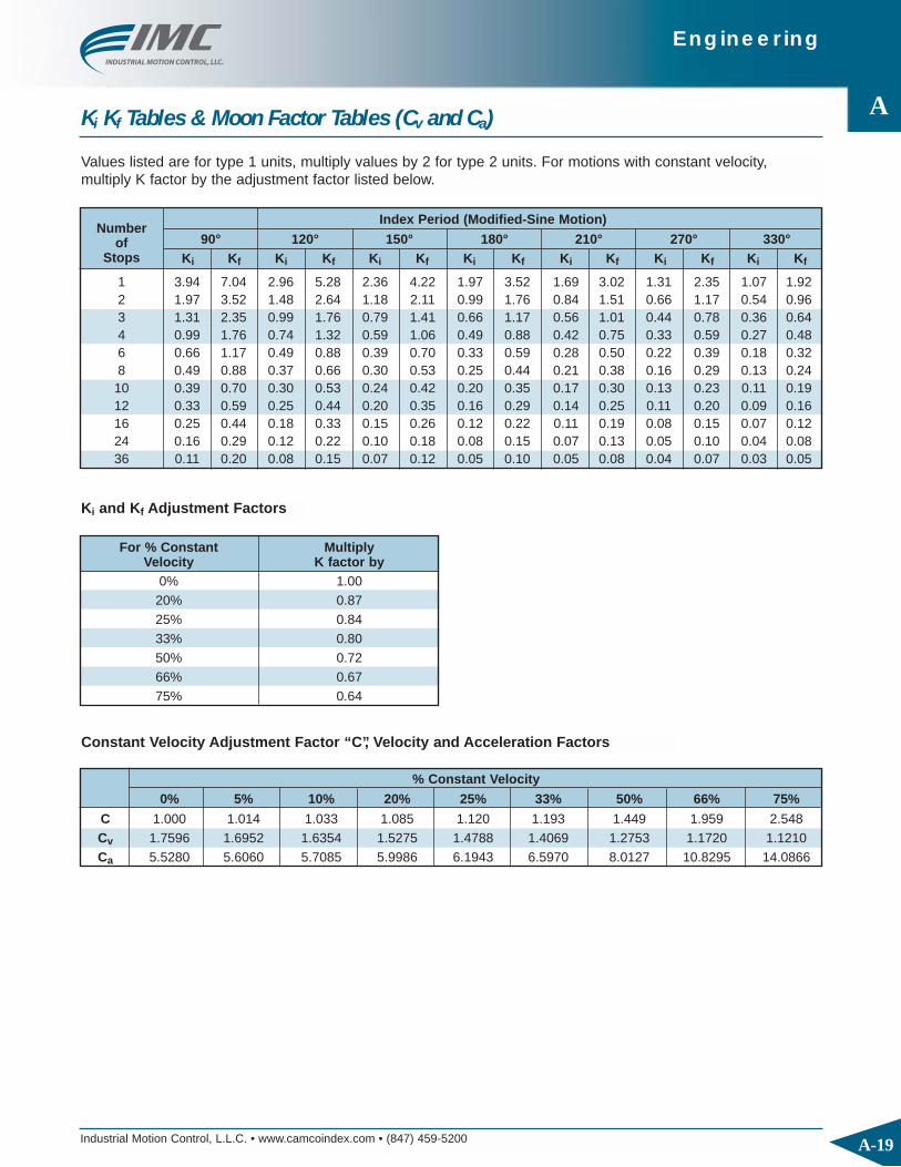
Ki Kf Tables & Moon Factor Tables (Cv and Ca)
Values listed are for type 1 units, multiply values by 2 for type 2 units. For motions with constant velocity, multiply K factor by the adjustment factor listed below.
Index Period (Modified-Sine Motion)
90° 120° 150° 180° 210° 270° 330°Ki Kf Ki Kf Ki Kf Ki Kf Ki Kf Ki Kf Ki Kf
Numberof
Stops
1 3.94 7.04 2.96 5.28 2.36 4.22 1.97 3.52 1.69 3.02 1.31 2.35 1.07 1.922 1.97 3.52 1.48 2.64 1.18 2.11 0.99 1.76 0.84 1.51 0.66 1.17 0.54 0.963 1.31 2.35 0.99 1.76 0.79 1.41 0.66 1.17 0.56 1.01 0.44 0.78 0.36 0.644 0.99 1.76 0.74 1.32 0.59 1.06 0.49 0.88 0.42 0.75 0.33 0.59 0.27 0.486 0.66 1.17 0.49 0.88 0.39 0.70 0.33 0.59 0.28 0.50 0.22 0.39 0.18 0.328 0.49 0.88 0.37 0.66 0.30 0.53 0.25 0.44 0.21 0.38 0.16 0.29 0.13 0.2410 0.39 0.70 0.30 0.53 0.24 0.42 0.20 0.35 0.17 0.30 0.13 0.23 0.11 0.1912 0.33 0.59 0.25 0.44 0.20 0.35 0.16 0.29 0.14 0.25 0.11 0.20 0.09 0.1616 0.25 0.44 0.18 0.33 0.15 0.26 0.12 0.22 0.11 0.19 0.08 0.15 0.07 0.1224 0.16 0.29 0.12 0.22 0.10 0.18 0.08 0.15 0.07 0.13 0.05 0.10 0.04 0.0836 0.11 0.20 0.08 0.15 0.07 0.12 0.05 0.10 0.05 0.08 0.04 0.07 0.03 0.05
Ki and Kf Adjustment Factors
For % Constant MultiplyVelocity K factor by
0% 1.0020% 0.8725% 0.8433% 0.8050% 0.7266% 0.6775% 0.64
Constant Velocity Adjustment Factor “C”, Velocity and Acceleration Factors
0% 5% 10% 20% 25% 33% 50% 66% 75%
C 1.000 1.014 1.033 1.085 1.120 1.193 1.449 1.959 2.548Cv 1.7596 1.6952 1.6354 1.5275 1.4788 1.4069 1.2753 1.1720 1.1210Ca 5.5280 5.6060 5.7085 5.9986 6.1943 6.5970 8.0127 10.8295 14.0866
% Constant Velocity

Engineering
A
A-20 Industrial Motion Control, L.L.C. • www.camcoindex.com • (847) 459-5200
Accuracy
0
10
20
30
40
50
60
70
80
90
0 2 4 6 8 10 12
Station Number
Accuracy
Acc
ura
cy (
arcs
eco
nd
s)
Maximum Error
Minimum Error
Accuracy
Vibration
Vibrations In Dwell
Criteria = Amplitude of less than 25 arc seconds in less than 0.250 seconds80.000
70.000
60.000
50.000
40.000
30.000
20.000
10.000
0.000
-10.000
-20.000
-30.000
-40.000
-50.000
-60.000
-70.000
-80.000
Time [seconds]
Am
plit
ude [
arc
seconds]
1.000 second dwell
0.500 0.750 1.0000.000 0.250
Application One Application Two
Cam-actuated index drives are frequently chosenbecause of their stability in dwell, especially whenoperating at high speeds. It is important to ascertainthat the entire system is well designed to prevent anyunwanted vibrations. Vibration is a function of theindex time, index rate, friction (dampens the system),input and output connections, torsional spring rate andthe natural frequency of the indexer and drivenmembers.
One simple method to avoid problems is to calculatethe ratio of the effective radius of gyration (k) to thecam follower pitch radius. This method does notalways produce consistent results. For example, asystem with a large effective radius of gyration canbe run at slow speed and there are no observablevibrations in dwell. Friction also helps prevent vibra-tion, as in the case of precision link conveyor systems.
(continued)
IMC intentionally chooses to state the Maximum Erroras the indexer’s worst possible accuracy. While someindex drive manufacturers use the average as theirstated accuracy and decline to state the repeatability,IMC takes a more conservative approach.
Measurement MethodThe output angular error of an index drive is measuredusing a laser collimator mounted to a precision rotarytable. The laser collimator is accurate to 2 arc seconds
and repeatable to 1 arc second. The indexer will make3 to 6 complete turns of its output and accuracymeasurements are recorded. The accuracy is themean between the maximum and minimum error. The repeatability is one-half the difference betweenthe maximum and minimum error.
Upon request, IMC can provide special accuracyreports for a particular indexer.
Engineering
A
A-21Industrial Motion Control, L.L.C. • www.camcoindex.com • (847) 459-5200
Vibration (continued)
IMC has developed stability criteria that effectivelypredict vibration effects. The criteria require that theamplitude of the vibration must be less than 25 arcseconds in 25% of the dwell time. IMC’s loadingprograms automatically check for this prerequisite.
Vibration can be avoided by following the recom-mended input and output connection methods andconfirming the vibration effect of the specificapplication using IMC’s loading software program.
Emergency Stop
Emergency stops can occur during any part of theindex motion. OSHA and other regulatory agencieswould like this stop to occur instantaneously. The lawsof physics require that the stop occurs within a finitetime – and this time cannot be too extended (for itwould defeat the purpose of an emergency stop).
Intuition suggests that the worst possible time for anemergency stop is at mid-motion of the index, at peakoutput velocity. At that moment we have the greatestamount of kinetic energy. The mathematics of motioncurves prove otherwise. For a particular type ofmotion, computer software analysis is the best methodfor determining the worst case scenario. Uponrequest, IMC engineering staff can evaluate and calculate the maximum expected stop times for specific applications and also evaluate the resultingstresses on the cam, cam followers, follower wheeland input components (reducer, motor, clutch andbrake). Normal forces on the cam follower must notexceed the vendor’s recommended maximum and thecam and camshaft stress must not exceed the
ultimate yield stress of the material (the cam andcamshaft are normally designed for fatigue and notstrength).
For an application with an Emergency stop requirement, IMC recommends that the drive packagefor an indexer should be a low ratio worm gear drive(10:1 or 15:1) along with a helical primary (5:1 or 5:1).This should be coupled to an air or hydraulic clutch-brake. Wet type or Hydro-viscous type clutch-brakesare recommended due to their low inertia of the cyclicparts and high heat dissipation capability. In contrast,dry type clutch-brakes wear quickly. In an Emergencystop mode, the clutch-brake disengages the motorsince the low-ratio gear combination (low ratio wormand helical primary combination) will be intentionallyback driven. The brake then dissipates the kineticenergy of the Emergency stop. For further details,please contact your IMC sales representative or IMC application engineer.
Engineering
A-22 Industrial Motion Control, L.L.C. • www.camcoindex.com • (847) 459-5200
A
Lubrication
IndexersIMC Index drives are normally shipped without oil toavoid possible leakage during transit. Each particularindex drive mounting position requires a different oillevel. A “bulls eye” type oil level sight gauge issupplied with each index drive. The unit should befilled with oil until the level reaches the middle of thissight gauge.
Lubricating oils for use in an index drive should behigh quality, well-refined petroleum oils or syntheticlubricants with extreme pressure additives. They maybe subject to high operating temperatures, so theymust have good resistance to oxidation. The lubricantmust meet these specifications: MIL-PRE-2105E orSAE 80W-140, ISO 220 or AGMA 5 with EP (extremepressure) additives.
Some units use grease rather than oil. In this case,the unit will be shipped with the grease. Generally,IMC uses a lithium grease such as Mobilith AW-2.
Gear ReducersLubricating oils for gear reducers should also be ofhigh quality, well-refined petroleum oils. These oilsshould meet AGMA 8 or 8A specifications or ISO 680or 1000 specifications. Oils with EP additives shouldnot be used if the reducer contains bronze parts.
If you have any questions regarding lubricants, pleasecontact IMC’s engineering department.
Overload Protection
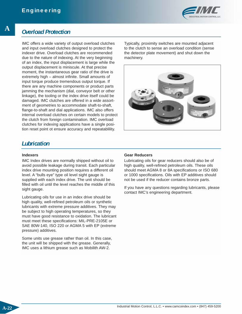
IMC offers a wide variety of output overload clutchesand input overload clutches designed to protect theindexer drive. Overload clutches are recommendeddue to the nature of indexing. At the very beginning of an index, the input displacement is large while theoutput displacement is miniscule. At that precisemoment, the instantaneous gear ratio of the drive isextremely high – almost infinite. Small amounts ofinput torque produce tremendous output torque. Ifthere are any machine components or product partsjamming the mechanism (dial, conveyor belt or otherlinkage), the tooling or the index drive itself could bedamaged. IMC clutches are offered in a wide assort-ment of geometries to accommodate shaft-to-shaft,flange-to-shaft and dial applications. IMC also offersinternal overload clutches on certain models to protectthe clutch from foreign contamination. IMC overloadclutches for indexing applications have a single posi-tion reset point ot ensure accuracy and repeatablility.
Typically, proximity switches are mounted adjacent to the clutch to sense an overload condition (sensethe detector plate movement) and shut down themachinery.

Engineering
A
A-23Industrial Motion Control, L.L.C. • www.camcoindex.com • (847) 459-5200
Axial, Radial & Moment Capacity
In addition to the B10 capacity, which is based on thecam follower capacity, an index drive also has a loadcapacity based on the bearings supporting the output.Several load conditions can be present in anapplication:
◆ Axial or Thrust Capacity is the maximum balanced load the indexer’s output bearing can support. Due to the use of large bearings, this loadcapacity generally does not need to be addressedin normal applications.
◆ Radial Capacity is the maximum side load of theoutput bearing, applied through and perpendicularto the axis of rotation.
◆ Moment Capacity is the maximum overturning orunbalanced load capacity of the output bearing.
The Axial, Radial and Moment capacities for mostindexers are listed in the appropriate product section.
Exceeding the capacity of the output bearing withany of these types of forces can cause permanentdeformation of the cam, fractured cam followers,or output bearing failure. Contact IMC engineeringfor analysis of application with special requirementsregarding any of these conditions.
Axial/Thrust
RadialMoment

Engineering
A
A-24 Industrial Motion Control, L.L.C. • www.camcoindex.com • (847) 459-5200
Input Considerations
Output Considerations
All load calculations are based on a constant velocityinput (camshaft speed) during the index. If there areany speed variations on the input shaft, these varia-tions are amplified on the output shaft (velocities areaccelerated and accelerations become jerk). It is veryimportant to have a controlled motor speed and areducer ratio sufficient to dampen any input speedvariations. If input belts are used, they must be tight-ened to prevent any slip or belt jumping when positive
torque changes to negative torque (input shaftstypically see both positive and negative torque in anindexing application). Pulleys should be maximized tothe largest diameter that can fit on the camshaft.Adjustable tensioning idler pulleys are highly recom-mended. If you have any questions regarding inputspeed control, please contact your local IMC salesrepresentative or IMC application engineer.
Indexing always imparts positive and negative torqueson the driven members. All connections should betight and doweled whenever possible. Shaft couplingconnections should have an interference fit and not
depend on the keyway for tightness, as any clearancein the key stock or keyways will eventually cause theconnection to loosen.
The IMC website, www.camcoindex.com, featuresuseful tools for those responsible for specifying, apply-ing and servicing Camco and Ferguson products.These include:
◆ 2-D and 3-D CAD drawings in a variety of formats
◆ General and Product-specific Service Manuals
◆ Product Catalogs
◆ Contact information for local sales representatives
6MM KEYWAY
6.69
3.44
(19MM)ø.7486
SIDE 2
10.5004.250
3.50
6.47
3.44
2.00
3.62 (SHAFT)
.25 5.94
2.16
ø8.66
3.44
9.16
1.30
ø
ø3.88
ALLOW .75 FOR WIRE TURN
IMC Online

Engineering
A
A-25Industrial Motion Control, L.L.C. • www.camcoindex.com • (847) 459-5200
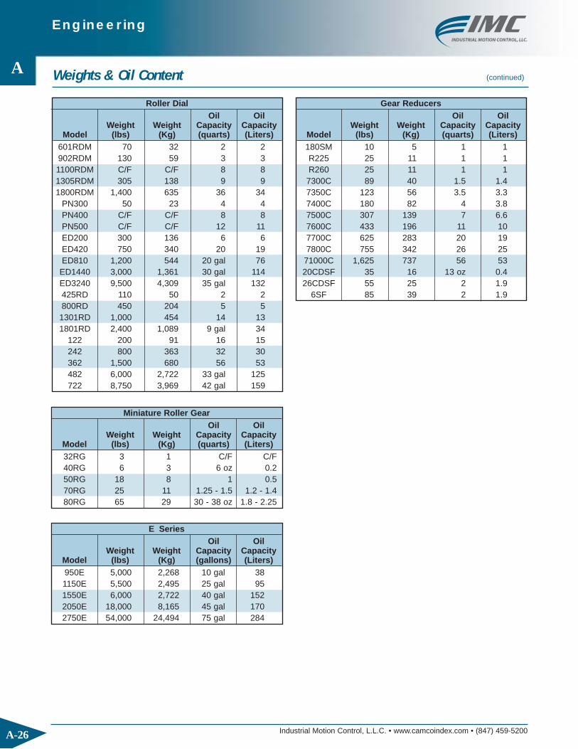
Weights & Oil Content
Right AngleOil Oil
Weight Weight Capacity CapacityModel (lbs) (Kg) (quarts) (Liters)301RA 15 7 C/F C/F400RA 33 15 1 1.0 401RA 55 25 1 1.0 512RA 80 36 2 2.0 662RA 160 73 6 6.0 663RA 130 59 4 4.0 900RA 220 100 6 6.01200RA 850 386 C/F C/F
ParallelOil Oil
Weight Weight Capacity CapacityModel (lbs) (Kg) (quarts) (Liters)250P 18 8 1 1 387P 55 25 2 2512P 135 61 5 5662P 430 195 10 10900P 750 340 20 19 1200P 1,100 499 48 451800P 3,000 1,361 95 90P200 20 9 C/F C/FP325 60 27 2 2 P400 85 39 4 4 P500 110 50 4 4P600 160 73 6 6P750 500 227 14 13P1050 750 340 24 23P1400 1,100 499 52 49P1700 3,000 1,361 76 72
CambotsOil Oil
Weight Weight Capacity CapacityModel (lbs) (Kg) (quarts) (Liters)
150RPP 45 20 2.5 2300RPP 110 50 4 4 500RPP 300 136 10 9900RPP 575 261 48 45
WBD-101 C/F C/F WBD-201 C/F C/F WBD-301 C/F C/F WBD-401 C/F C/F 140LPP 55 25 240LPP 80 36 380LPP 200 91
4120LPP 340 154 LPP-101 C/F C/F LPP-201 C/F C/F LPP-301 C/F C/FLPP-401 C/F C/F
Overload Clutches
Weight WeightModel (lbs) (Kg)0.39 5 2 2.3 10 5 4 17 8 6 25 11
7.8 20 9 11 40 18 18 75 34 35 57 26 31 123 56
Torq Gard Clutches
Weight WeightModel (lbs) (Kg)TG3 2 1 TG6 2 1
TG20 3 1 TG60 6 3
TG200 12 5 TG400 43 20 TG800 43 20
Roller GearOil Oil
Weight Weight Capacity CapacityModel (lbs) (Kg) (quarts) (Liters)350RG 35 16 2 1 500RG 350 159 5 5600RG 390 177 7 7 700RG 400 181 10 9 FD-100 10 5 7 oz 0.2 FD-162 50 23 2 2 FD-200 115 52 4 4 FD-250 125 57 7 7 FD-300 300 136 10 9FD-451 560 254 12 11 FD-501 900 408 22 21
These units aregrease-filled. Consult
the model-specificservice manual for
lubricationinformation.
Engineering
A
A-26 Industrial Motion Control, L.L.C. • www.camcoindex.com • (847) 459-5200
Roller DialOil Oil
Weight Weight Capacity CapacityModel (lbs) (Kg) (quarts) (Liters)
601RDM 70 32 2 2 902RDM 130 59 3 31100RDM C/F C/F 8 8 1305RDM 305 138 9 9 1800RDM 1,400 635 36 34
PN300 50 23 4 4PN400 C/F C/F 8 8 PN500 C/F C/F 12 11 ED200 300 136 6 6 ED420 750 340 20 19 ED810 1,200 544 20 gal 76 ED1440 3,000 1,361 30 gal 114ED3240 9,500 4,309 35 gal 132 425RD 110 50 2 2 800RD 450 204 5 5 1301RD 1,000 454 14 131801RD 2,400 1,089 9 gal 34
122 200 91 16 15 242 800 363 32 30 362 1,500 680 56 53 482 6,000 2,722 33 gal 125 722 8,750 3,969 42 gal 159
Weights & Oil Content (continued)
Miniature Roller GearOil Oil
Weight Weight Capacity CapacityModel (lbs) (Kg) (quarts) (Liters)32RG 3 1 C/F C/F 40RG 6 3 6 oz 0.250RG 18 8 1 0.570RG 25 11 1.25 - 1.5 1.2 - 1.480RG 65 29 30 - 38 oz 1.8 - 2.25
E SeriesOil Oil
Weight Weight Capacity CapacityModel (lbs) (Kg) (gallons) (Liters)950E 5,000 2,268 10 gal 381150E 5,500 2,495 25 gal 951550E 6,000 2,722 40 gal 1522050E 18,000 8,165 45 gal 1702750E 54,000 24,494 75 gal 284
Gear ReducersOil Oil
Weight Weight Capacity CapacityModel (lbs) (Kg) (quarts) (Liters)180SM 10 5 1 1 R225 25 11 1 1R260 25 11 1 1
7300C 89 40 1.5 1.47350C 123 56 3.5 3.37400C 180 82 4 3.87500C 307 139 7 6.67600C 433 196 11 107700C 625 283 20 197800C 755 342 26 25
71000C 1,625 737 56 5320CDSF 35 16 13 oz 0.426CDSF 55 25 2 1.9
6SF 85 39 2 1.9

FeaturesThe RDM Series Index Drive is ideal forrotary dial applications with featuresincluding:
◆ Large Output Mounting Surface supported by 4-point contact bearingoffering superior thrust and momentcapacity
◆ Large Center Thru Hole
◆ Low Profile
◆ Complete, Motorized Drive Packages
◆ Optional Output Overload Clutch

Industrial Motion Control, L.L.C. • www.camcoindex.com • (847) 459-5200
RDM Index Drives
B
B-2
80RDM Indexer Capacities
80RDM
205
4X M8 X 16
6 X 3.5(N9)
52.565
2X ø6.8,2X 8.8,
13080
FAR SIDE
80130
40
2X 19
15
230 80
65
ø107
FAR SIDE
NEAR SIDE4X M8,
4X ø
42
42
4X M6 X 12
13
42
13
42
98
ø80
ø125
ø160 h7 h6
1104
THRUø70
ALL DIMENSIONS = MILLIMETERS
Technical SpecificationsOutput Load Capacity – loads carried during index
Radial 730 lbs
Thrust/Axial 1,810 lbs
Moment 1,810 in.-lbs
Other Motions (stops and index periods) available. Contact your lMC sales representative for more information.
All dimensions are subject to change. For actual dimensions, please request the current drawing from IMC.
Typical Application Dial Diameter: 8 in. to 28 in.
Accuracy ±44 arcsec / ±.003" at 14" Radius
Repeatability ±22 arcsec / ±.0014" at 14" Radius
Stops Index Motion B10 Capacity Internal Inertia Model (S) Period (β) at 50 RPM (in-lb) (lb-in2)2 330 msc.50 716 28 80RDM2H16-330 3 330 msc.25 798 28 80RDM3H16-330 4 330 msc.33 1455 28 80RDM4H20-330 6 270 ms 1540 30 80RDM6H20-2708 270 ms 1197 29 80RDM8H16-270
270 ms 1661 30 80RDM12H20-27012 180 ms 1817 30 80RDM12H20-180
120 msc.33 2222 30 80RDM12H20-120 270 ms 1260 29 80RDM16H16-270
16180 ms 1392 29 80RDM16H16-180120 ms 1473 29 80RDM16H16-12090 msc.33 1724 29 80RDM16H16-90
24270 ms 2012 30 80RDM24H20-270 II180 ms 2233 30 80RDM24H20-180 II
32270 ms 1523 29 80RDM32H16-270 II180 ms 1681 29 80RDM32H16-180 II
4 360 c.v. 482 30 80RDM0H20-360 4:18 360 c.v. 370 29 80RDM0H16-360 8:112 360 c.v. 547 30 80RDM0H20-360 12:116 360 c.v. 384 29 80RDM0H16-360 16:1
Industrial Motion Control, L.L.C. • www.camcoindex.com • (847) 459-5200
RDM Index Drives
B
B-3
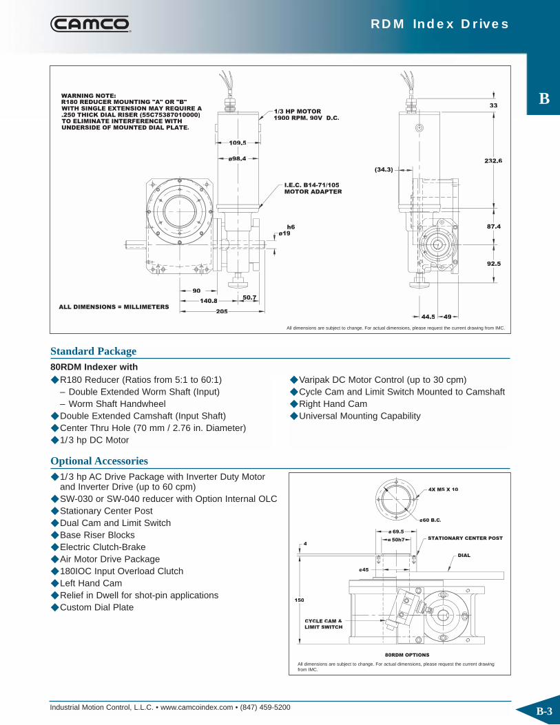
1900 RPM. 90V D.C. 1/3 HP MOTOR
MOTOR ADAPTERI.E.C. B14-71/105
ø19
140.8
90
205
50.7
UNDERSIDE OF MOUNTED DIAL PLATE. TO ELIMINATE INTERFERENCE WITH .250 THICK DIAL RISER (55C75387010000) WITH SINGLE EXTENSION MAY REQUIRE AR180 REDUCER MOUNTING "A" OR "B"WARNING NOTE:
h6
ø98.4
109.5
44.5 49
92.5
(34.3)
87.4
232.6
33
ALL DIMENSIONS = MILLIMETERS
◆ R180 Reducer (Ratios from 5:1 to 60:1)– Double Extended Worm Shaft (Input)– Worm Shaft Handwheel
◆ Double Extended Camshaft (Input Shaft)◆ Center Thru Hole (70 mm / 2.76 in. Diameter)◆ 1/3 hp DC Motor
Standard Package80RDM Indexer with
◆ Varipak DC Motor Control (up to 30 cpm)◆ Cycle Cam and Limit Switch Mounted to Camshaft◆ Right Hand Cam◆ Universal Mounting Capability
DIAL
4X M5 X 10
STATIONARY CENTER POSTø
ø
150
4
ø45
ø60 B.C.
CYCLE CAM &
LIMIT SWITCH
80RDM OPTIONS
Optional Accessories◆ 1/3 hp AC Drive Package with Inverter Duty Motor
and Inverter Drive (up to 60 cpm)◆ SW-030 or SW-040 reducer with Option Internal OLC◆ Stationary Center Post◆ Dual Cam and Limit Switch◆ Base Riser Blocks◆ Electric Clutch-Brake ◆ Air Motor Drive Package◆ 180IOC Input Overload Clutch ◆ Left Hand Cam◆ Relief in Dwell for shot-pin applications ◆ Custom Dial Plate
All dimensions are subject to change. For actual dimensions, please request the current drawing from IMC.
All dimensions are subject to change. For actual dimensions, please request the current drawingfrom IMC.

Industrial Motion Control, L.L.C. • www.camcoindex.com • (847) 459-5200
RDM Index Drives
B
B-4
601RDM Indexer Capacities
601RDM
2X ø 312
2X ø .3125
4X .312-18UNC
5X .250-20UNC
6X 312-18UNC
ø 8.66 ø 1.75ø 3.500
ø 6.50
2.16
.236 KEYWAY
.74862X ø
4.250
10.50
3.50
.25 5.94
4.59
6.69
4X ø .406
3.613.00
1.81
30°
3.00
1.81
30°
R5.09.375
45°ø 6.000
55°
ø 3.000
55°
8.66
THRU
6.69
±.01
+.000-.001
-+.0005
.0000
(6MM)
(19MM)
Technical SpecificationsOutput Load Capacity – loads carried during index
Radial 910 lbs
Thrust/Axial 2,270 lbs
Moment 3,180 in.-lbs
Other Motions (stops and index periods) available. Contact your lMC sales representative for more information.
All dimensions are subject to change. For actual dimensions, please request the current drawing from IMC.
Typical Application Dial Diameter: 12 in. to 36 in.
Accuracy ±39 arcsec / ±.003" at 18" Radius
Repeatability ±22 arcsec / ±.002" at 18" Radius
Stops Index Motion B10 Capacity Internal Inertia Model (S) Period (β) at 50 RPM (in-lb) (lb-in2)2 330 msc.67 1555 112 601RDM2H20-330 3 330 msc.33 2950 112 601RDM3H24-330 4 330 msc.33 3683 112 601RDM4H24-330 6 270 ms 4025 112 601RDM6H24-270
8270 msc.33 5035 112 601RDM8H24-270 180 msc.67 6758 112 601RDM8H24-180 270 ms 4452 112 601RDM12H24-270
12 180 ms 4985 112 601RDM12H24-180120 msc.33 6225 112 601RDM12H24-120 270 ms 4511 112 601RDM16H24-270
16 180 ms 5061 112 601RDM16H24-180120 msc.50 6780 112 601RDM16H24-120
24270 ms 5879 112 601RDM24H24-270 II180 ms 6479 112 601RDM24H24-180 II
32270 ms 5937 112 601RDM32H24-270 II180 ms 6651 112 601RDM32H24-180 II
4 360 c.v. 1110 110 601RDM0H24-360 4:16 360 c.v. 1212 110 601RDM0H24-360 6:18 360 c.v. 1274 112 601RDM0H24-360 8:112 360 c.v. 1286 110 601RDM0H24-360 12:1

Industrial Motion Control, L.L.C. • www.camcoindex.com • (847) 459-5200
RDM Index Drives
B
B-5
1/3 HP MOTOR1900 RPM, 90V D.C.
MOTOR ADAPTOR
ø.7846 (19MM)
4.47
6.47
8.47
4.31
3.88
3.72
3.44
9.16
1.30
2.161.75
◆ R180 Reducer (Ratios from 5:1 to 60:1)– Double Extended Worm Shaft (Input)– Worm Shaft Handwheel
◆ Double Extended Camshaft (Input Shaft)◆ Center Thru Hole (1.75 in. Diameter)
Standard Package601RDM Indexer with
◆ 1/3 hp DC Motor◆ Varipak DC Motor Control (up to 30 cpm)◆ Cycle Cam and Limit Switch Mounted to Camshaft◆ Right Hand Cam
ø.75 THRU
10.00
.19ø1.000
+.000
4.0D
ø1.734
4X #10-24UNC
4X ø.281
DIAL
STATIONARY CENTER POST
ø1.375
ø2.250
CYCLE CAM &
LIMIT SWITCH
OVERLOAD CLUTCH
-.001(CUSTOMER TO MOUNTTO MACHINE BASE)
(LOWER MTG HOLES)
Optional Accessories◆ 1/3 hp AC Drive Package with Inverter Duty Motor
and Inverter Drive (up to 60 cpm) ◆ R225 Heavy Duty Reducer (ratios from 5:1 to 60:1)
with 1 hp DC Motor ◆ Output Overload Clutch model 4.0D
– Available Settings (in-lbs): 420, 620, 750, 1150,1750, 2940, 4000
◆ Stationary Center Post◆ Dual Cam and Limit Switch◆ Base Riser Blocks◆ Electric Clutch-Brake ◆ Air Clutch-Brake (requires R225 Reducer)◆ Air Motor Drive Package◆ 180IOC or 225IOC Input OLC ◆ Left Hand Cam◆ Relief in Dwell for shot-pin applications◆ Custom Dial Plate
All dimensions are subject to change. For actual dimensions, please request the current drawing from IMC.
All dimensions are subject to change. For actual dimensions, please request the current drawingfrom IMC.
Industrial Motion Control, L.L.C. • www.camcoindex.com • (847) 459-5200
RDM Index Drives
B
B-6
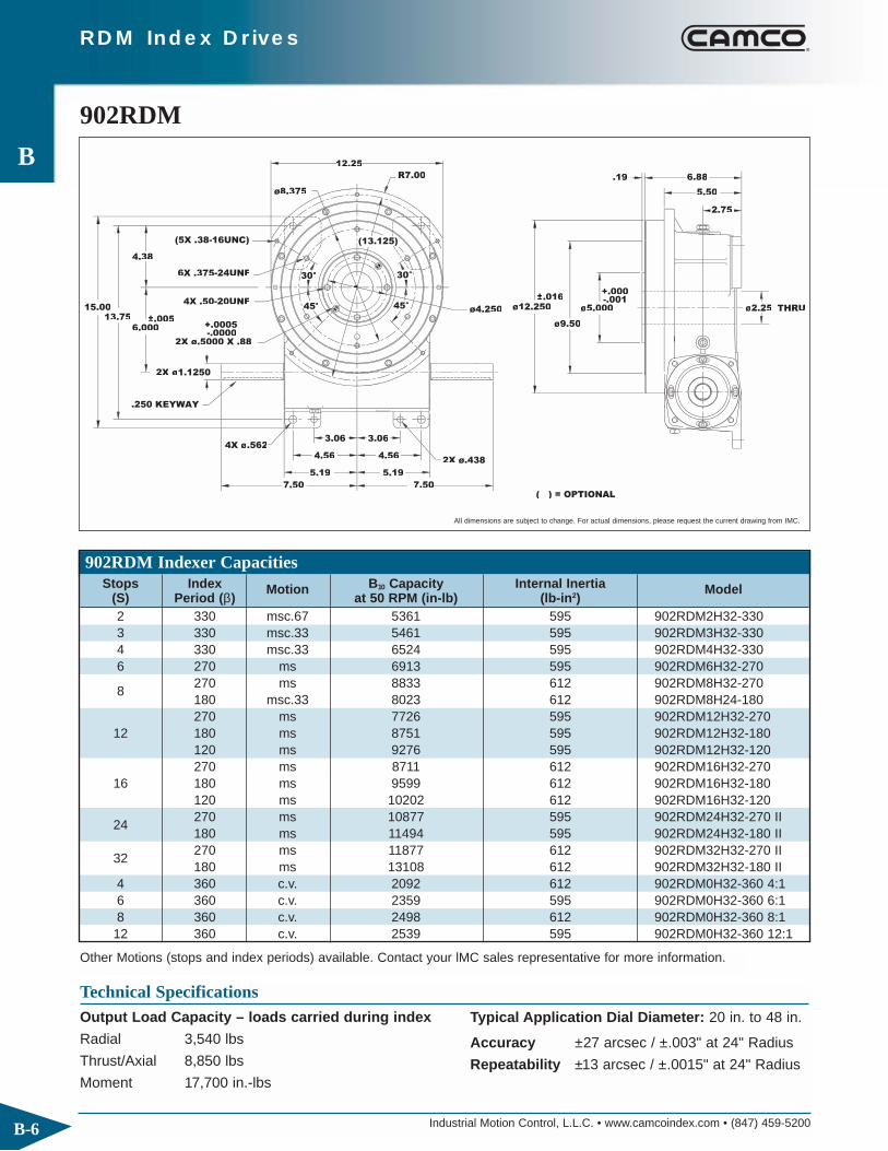
902RDM Indexer Capacities
902RDM
7.50
15.0013.75
.250 KEYWAY
4X .50-20UNF
6.000
5.19
4.56
5.19
4.56
3.064X ø.5622
2X ø.438
2X ø
4.38
(5X .38-16UNC)
6X .375-24UNF
12.251 5
2X ø.5000 X .88
.19
ø12.250
ø9.50
ø5.000
°
°
°
°
R7.00
ø4.250
ø8.375 5.50
6.88
2.75
7.500
ø2.25 THRU
+.000±.016
±.005
-.0000+.0005
( ) = OPTIONAL
Technical SpecificationsOutput Load Capacity – loads carried during index
Radial 3,540 lbs
Thrust/Axial 8,850 lbs
Moment 17,700 in.-lbs
Other Motions (stops and index periods) available. Contact your lMC sales representative for more information.
All dimensions are subject to change. For actual dimensions, please request the current drawing from IMC.
Typical Application Dial Diameter: 20 in. to 48 in.
Accuracy ±27 arcsec / ±.003" at 24" Radius
Repeatability ±13 arcsec / ±.0015" at 24" Radius
Stops Index Motion B10 Capacity Internal Inertia Model (S) Period (β) at 50 RPM (in-lb) (lb-in2)2 330 msc.67 5361 595 902RDM2H32-330 3 330 msc.33 5461 595 902RDM3H32-330 4 330 msc.33 6524 595 902RDM4H32-330 6 270 ms 6913 595 902RDM6H32-270
8270 ms 8833 612 902RDM8H32-270180 msc.33 8023 612 902RDM8H24-180270 ms 7726 595 902RDM12H32-270
12 180 ms 8751 595 902RDM12H32-180120 ms 9276 595 902RDM12H32-120270 ms 8711 612 902RDM16H32-270
16 180 ms 9599 612 902RDM16H32-180120 ms 10202 612 902RDM16H32-120
24270 ms 10877 595 902RDM24H32-270 II180 ms 11494 595 902RDM24H32-180 II
32270 ms 11877 612 902RDM32H32-270 II180 ms 13108 612 902RDM32H32-180 II
4 360 c.v. 2092 612 902RDM0H32-360 4:16 360 c.v. 2359 595 902RDM0H32-360 6:18 360 c.v. 2498 612 902RDM0H32-360 8:112 360 c.v. 2539 595 902RDM0H32-360 12:1

Industrial Motion Control, L.L.C. • www.camcoindex.com • (847) 459-5200
RDM Index Drives
B
B-7
8.62
5.195
ØØ.8750
2.75
13.001
1.75
2.75
7.50
+.0000-.0005
56C FRAME 9 AMP
1 HP MOTOR90V D.C. 1800 RPM TEFC
12.75 MAXØØ6.62
ØØ4.62
ØØ5.25
2.250
4.12
3.31
3.16
(OPTIONAL) RISER PACKAGE FOR USEWITH REDUCER MOUNTING C ANDOPTIONAL MOTOR (NOT REQUIRED IF REDUCER OVERHANGSTABLE)
3.12
56C MOTOR ADAPTOR
Ø.6875
4.81
.188 KEYWAY
-.0010+.0000
◆ R225 Reducer (Ratios from 5:1 to 60:1)◆ Double Extended Camshaft (Input Shaft)◆ Center Thru Hole (2.25 in. Diameter)◆ 1 hp DC Motor
Standard Package902RDM Indexer with
◆ Varipak DC Motor Control (up to 30 cpm)◆ Cycle Cam and Limit Switch Mounted to Camshaft◆ Right Hand Cam
10.12
Ø1.75 THRU
.25 Ø2.000-.001
4X .375-16UNC
7.8D
Ø3.375
DIAL
STATIONARY CENTER POST
+.000
Ø2.750
OVERLOAD CLUTCH
CYCLE CAM &LIMIT SWITCH
Optional Accessories◆ 1 hp AC Drive Package with Inverter Duty Motor
and Inverter Drive (up to 60 cpm)◆ R260 Reducer (Ratios from 5:1 to 60:1)◆ Output Overload Clutch model 7.8D
– Available Settings (in-lbs): 1400, 1700, 2600,3200, 4200, 5000, 7200, 10000
◆ Stationary Center Post◆ Dual Cam and Limit Switch◆ Base Riser Blocks◆ Electric Clutch-Brake◆ Air Clutch-Brake ◆ Air Motor Drive Package◆ 225IOC or 260IOC Input OLC◆ Left Hand Cam◆ Relief in Dwell for shot-pin applications◆ Custom Dial Plate
All dimensions are subject to change. For actual dimensions, please request the current drawing from IMC.
All dimensions are subject to change. For actual dimensions, please request the current drawingfrom IMC.
Industrial Motion Control, L.L.C. • www.camcoindex.com • (847) 459-5200
RDM Index Drives
B
B-8
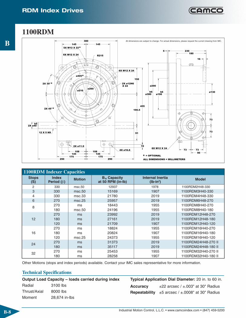
1100RDM Indexer Capacities
1100RDM
6X M12 X 24
X 242X ø12H6
4X ø16.6
12 X 5 N9
2X ø11.9
5X M12 X 22*
8X M12 X 24
8X M12 X 24
* = OPTIONAL
290
2X ø40h5
2X 45°*
108108
175145
290175
145
2X 30°*ø260
ø210
ø405*
145
380
145
R215
73
19
91
190.5
455
7390
73
73
230
ø290
h6ø380
150
h6ø190
6
ø130
180
16
ALL DIMENSIONS = MILLIMETERS
Technical SpecificationsOutput Load Capacity – loads carried during index
Radial 3100 lbs
Thrust/Axial 8000 lbs
Moment 28,674 in-lbs
Other Motions (stops and index periods) available. Contact your lMC sales representative for more information.
All dimensions are subject to change. For actual dimensions, please request the current drawing from IMC.
Typical Application Dial Diameter: 20 in. to 60 in.
Accuracy ±22 arcsec / ±.003" at 30" Radius
Repeatability ±5 arcsec / ±.0008" at 30" Radius
Stops Index Motion B10 Capacity Internal Inertia Model(S) Period (β) at 50 RPM (in-lb) (lb-in2)2 330 msc.50 12937 1978 1100RDM2H48-3303 330 msc.50 15169 1907 1100RDM3H40-3304 330 msc.33 21780 2019 1100RDM4H48-3306 270 msc.25 25957 2019 1100RDM6H48-270
8 270 ms 18443 1955 1100RDM8H40-270180 msc.50 24196 1955 1100RDM8H40-180270 ms 23992 2019 1100RDM12H48-270
12 180 ms 27161 2019 1100RDM12H48-180120 ms 21709 1907 1100RDM12H40-120270 ms 18824 1955 1100RDM16H40-270
16 180 ms 20824 1907 1100RDM16H40-180120 msc.25 24373 1955 1100RDM16H40-120
24 270 ms 31373 2019 1100RDM24H48-270 II180 ms 35117 2019 1100RDM24H48-180 II
32 270 ms 25453 1955 1100RDM32H40-270 II180 ms 28258 1907 1100RDM32H40-180 II

Industrial Motion Control, L.L.C. • www.camcoindex.com • (847) 459-5200
RDM Index Drives
B
B-9
(1.000") OPTIONAL
292.5
290 396
ø 179
90125 74
(170) OPTIONAL
243
76.2[3.00"]
401
145TC MOTOR
ADAPTOR
1.5 HP MOTOR,
TEFC 180V D.C.,
1800 RPM
ALL DIMENSIONS = MILLIMETERS
◆ 7300C Reducer (Ratios from 5:1 to 60:1)◆ Double Extended Camshaft (Input Shaft)◆ Center Thru Hole (130 mm / 5.1 in. Diameter)◆ 1.5 hp DC motor
Standard Package1100RDM Indexer with
◆ Varipak DC Motor Control (up to 30 cpm)◆ Cycle Cam and Limit Switch Mounted to Camshaft◆ Right Hand Cam
MOTOR FRAME
OPTIONAL BRAKE MOTOR
SEW KH47
"DM"
197
145
145
197
IEC71
IEC90
IEC80
IEC100
"LB""LM"
269
319
199
249
85
85
64
64
1100RDM WITH OPTIONAL KH47 REDUCER
73
(22) 76166
"DM"
7.2
"LM""LB"
Optional Accessories◆ KH47 Reducer and AC Motor with Optional Brake◆ AC drive package with Inverter Duty Motor and
Inverter Drive (up to 60 cpm)◆ 7350C Heavy Duty Reducer (Ratios from 5:1 to 60:1)◆ Stationary Center Post◆ Dual Cam and Limit Switch◆ Electric Clutch-Brake◆ Air Clutch Brake◆ 300IOC Input OLC◆ Left Hand Cam◆ Relief in Dwell for shot-pin applications◆ Custom Dial Plate
All dimensions are subject to change. For actual dimensions, please request the current drawing from IMC.
All dimensions are subject to change. For actual dimensions, please request the current drawingfrom IMC.

Industrial Motion Control, L.L.C. • www.camcoindex.com • (847) 459-5200
RDM Index Drives
B
B-10
1305RDM Indexer Capacities
1305RDM
+.0000
+.000±.01
4.188
.75
Ø5.00 THRU
.31 10.875
8.688
Ø18.00
Ø14.50
Ø7.500
45°45
30
(5X .50-13UNC)
18.00
12X .50-13UNC
6X .50-13UNC
R10
21.875
7.50
9.000
4X Ø.6882X Ø.469
.375 KEYWAY
2X Ø1.6875
13.25
7.757.75
6.5006.500
5.005.00
Ø8.250
Ø
(Ø19.000)
( ) = OPTIONAL
13.25
-.0005
Technical SpecificationsOutput Load Capacity – loads carried during index
Radial 4,650 lbs
Thrust/Axial 11,650 lbs
Moment 34,850 in.-lbs
Other Motions (stops and index periods) available. Contact your lMC sales representative for more information.
All dimensions are subject to change. For actual dimensions, please request the current drawing from IMC.
Typical Application Dial Diameter: 20 in. to 72 in.
Accuracy ±38 arcsec / ±.007" at 36" Radius
Repeatability ±10 arcsec / ±.002" at 36" Radius
Stops Index Motion B10 Capacity Internal Inertia Model (S) Period (β) at 50 RPM (in-lb) (lb-in2)2 330 msc.50 11374 4273 1305RDM2H40-3303 330 msc.67 24389 4009 1305RDM3H48-3304 330 msc.25 21640 4415 1305RDM4H48-3306 270 ms 24014 4415 1305RDM6H48-2708 270 msc.33 29334 4486 1305RDM8H48-2708 180 ms 24607 4344 1305RDM8H40-180
270 ms 24919 4415 1305RDM12H48-27012 180 ms 27372 4415 1305RDM12H48-180
120 ms 28835 4415 1305RDM12H48-120270 ms 26692 4486 1305RDM16H48-270
16 180 ms 29538 4486 1305RDM16H48-180120 msc.33 36506 4486 1305RDM16H48-120
24270 ms 33371 4415 1305RDM24H48-270 II180 ms 36568 4415 1305RDM24H48-180 II
32270 ms 36514 4486 1305RDM32H48-270 II180 ms 40186 4486 1305RDM32H48-180 II
4 360 c.v. 6743 4415 1305RDM0H48-360 4:16 360 c.v. 7381 4415 1305RDM0H48-360 6:18 360 c.v. 7755 4486 1305RDM0H48-360 8:112 360 c.v. 7830 4415 1305RDM0H48-360 12:1

Industrial Motion Control, L.L.C. • www.camcoindex.com • (847) 459-5200
RDM Index Drives
B
B-11
(Ø1.000)
16.44
12.38
7.75 3.62
Ø1.6875
+.0000-.0005
6.633
3.000
11.3
4.5
9.56
145TC MOTOR
ADAPTOR
16.50 (OPTIONAL) RISER
PACKAGE FOR USE
WITH REDUCER
MTG. "D". (NOT
REQUIRED
IF REDUCER
OVERHANGS
TABLE.)
2 HP. MOTOR180 VDC., 1800 RPM., TEFC
6.977
.75
WORMSHAFT EXTENSION(OPTIONAL)
(6.69)
◆ 7300C Reducer (Ratios from 5:1 to 60:1)◆ Double Extended Camshaft (Input Shaft)◆ Center Thru Hole (5.00 in. Diameter)◆ 2 hp DC Motor
Standard Package1305RDM Indexer with
◆ Varipak DC Motor Control (up to 30 cpm)◆ Cycle Cam and Limit Switch Mounted to Camshaft◆ Right Hand Cam
Ø3.50 THRU
16.12
.25
6X Ø.531
Ø
6X .38-16UNC
32D
Ø4.990
DIAL
STATIONARY CENTER POST
CYCLE CAM &LIMIT SWITCH
Ø6.5000Ø4.375
OVERLOAD CLUTCH
-.001+.000
(CUSTOMER TO MOUNTTO MACHINE BASE)
1305RDM OPTIONS
(LOWER MTG HOLES)
Optional Accessories◆ 2 hp AC Drive Package with Inverter Duty Motor
and Inverter Drive (up to 60 cpm) ◆ 7350C Heavy Duty Reducer (Ratios from 5:1 to 60:1)◆ Output Overload Clutch model 32D
– Available Settings (in-lbs): 8500, 13000,20000, 31000
◆ Stationary Center Post◆ Dual Cam and Limit Switch◆ Base Riser Blocks◆ Electric Clutch-Brake◆ Air Clutch-Brake◆ 300IOC or 350IOC Input OLC◆ Left Hand Cam◆ Relief in Dwell for shot-pin applications◆ Custom Dial Plate
All dimensions are subject to change. For actual dimensions, please request the current drawing from IMC.
All dimensions are subject to change. For actual dimensions, please request the current drawingfrom IMC.

Industrial Motion Control, L.L.C. • www.camcoindex.com • (847) 459-5200
RDM Index Drives
B
B-12
1800RDM Indexer Capacities
1800RDM
5X .625-11
4X Ø.594
.500 KEYWAY
15.500.31
Ø20.38
8X .625-11
4.250
4.250
1.12
6.250
4.250
-.001Ø9.000±.01 Ø6.50
2X Ø2.1875
11.50
24.50
R13.5
30°
31.250
12.500
15.75
°°
9.500
7.25
10.75
30°
45°
9.500
10.752X Ø.594
15.75
4X Ø.781
22.5°
X 1.25 DEEP
7.25
Ø20.50
1.38 DEEP
+.000
12X .625-11 8X .625-11X 1.25 DEEP
X 1.25 DEEP
X 1.00 DEEP
Ø10.000
Technical SpecificationsOutput Load Capacity – loads carried during index
Radial 5,850 lbs
Thrust/Axial 14,550 lbs
Moment 61,200 in.-lbs
Other Motions (stops and index periods) available. Contact your lMC sales representative for more information.
All dimensions are subject to change. For actual dimensions, please request the current drawing from IMC.
Typical Application Dial Diameter: 26 in. to 96 in.
Accuracy ±27 arcsec / ±.006" at 48" Radius
Repeatability ±7 arcsec / ±.0016" at 48" Radius
Stops Index Motion B10 Capacity Internal Inertia Model (S) Period (β) at 50 RPM (in-lb) (lb-in2)2 330 msc.50 27554 18407 1800RDM2H56-330 3 330 msc.33 48803 18407 1800RDM3H64-330 4 330 msc.25 56570 18407 1800RDM4H64-330 6 270 ms 64301 18407 1800RDM6H64-2708 270 ms 64868 18985 1800RDM8H64-270
270 ms 71214 18407 1800RDM12H64-27012 180 ms 77925 18407 1800RDM12H64-180
120 ms 81918 18407 1800RDM12H64-120270 ms 64035 18985 1800RDM16H64-270
16 180 ms 71219 18985 1800RDM16H64-180120 msc.33 86845 18407 1800RDM16H64-120
24270 ms 86546 18407 1800RDM24H64-270 II180 ms 93113 18985 1800RDM24H64-180 II
32270 ms 86288 18985 1800RDM32H64-270 II180 ms 96447 18985 1800RDM32H64-180 II
4 360 c.v. 15430 18985 1800RDM0H64-360 4:16 360 c.v. 16867 18985 1800RDM0H64-360 6:18 360 c.v. 17710 18985 1800RDM0H64-360 8:112 360 c.v. 17875 18985 1800RDM0H64-360 12:116 360 c.v. 18410 18985 1800RDM0H64-360 16:1

Industrial Motion Control, L.L.C. • www.camcoindex.com • (847) 459-5200
RDM Index Drives
B
B-13
180 V.DC.,1800RPM, TEFC3 HP. MOTOR
10.75
ø2.1875
17.50
5.00
1.00
4.000
15.19
6.2506
MOTOR ADAPTOR145TC
(ø1.500)
10.94
(19.75)
(ø8.50)15.500
6.00 TYP
(OPTIONAL) RISER MAY BE USED WITHMTG. "C" TO PROVIDEREDUCER CLEARANCEWITH TABLE.
(3.00)
(9.31)
WORMSHAFT EXTENSION(OPTIONAL)
◆ 7400C Reducer (Ratios from 5:1 to 60:1)◆ Double Extended Camshaft (Input Shaft)◆ Center Thru Hole (6.50 in. Diameter)
Standard Package1800RDM Indexer with
◆ 3 hp DC Motor◆ Cycle Cam and Limit Switch Mounted to Camshaft◆ Right Hand Cam
6X .437-14UNCX .88 DEEPON 5.812 B.C.
6X .781 ø EQ. SP.ON 8.500 B.C.(LOWER MOUNTINGHOLES)
22.00
CONDUIT ENTRY
CYCLE CAM &LIMIT SWITCH
DIAL
61D OVERLOAD CLUTCH (OPTIONAL)
STATIONARY CENTER POST (CUSTOMER TOMOUNT TO MACHINEBASE)ø5.125
4.75 ø THRUHOLE
.25
+.000
ø6.490
1800RDM OPTIONS
Optional Accessories◆ 2 or 3 hp AC Drive Package with Inverter Duty Motor
and Inverter Drive (up to 60 cpm) ◆ 2 hp DC Motor with Varipak DC Motor Control
(up to 30 cpm) ◆ 7500C Heavy Duty Reducer (Ratios from 5:1 to 60:1)◆ Output Overload Clutch model 61D
– Available Settings (in-lbs): 23000, 36000, 44000,50000, 60000
◆ Stationary Center Post◆ Dual Cam and Limit Switch◆ Base Riser Blocks◆ Electric Clutch-Brake◆ Air Clutch-Brake◆ 400IOC or 500IOC Input OLC◆ Left Hand Cam◆ Relief in Dwell for shot-pin applications◆ Custom Dial Plate
All dimensions are subject to change. For actual dimensions, please request the current drawing from IMC.
All dimensions are subject to change. For actual dimensions, please request the current drawingfrom IMC.

Industrial Motion Control, L.L.C. • www.camcoindex.com • (847) 459-5200
RDM Index Drives
B
B-14
1. Model
2. Input Shaft Configuration◆ Side 1◆ Side 2◆ Double Input – DI (Standard)
1. Model
2. Ratio◆ 5:1, 10:1, 15:1, 20:1, 25:1, 30:1, 40:1, 50:1, 60:1
3. Motor Adapter
4. Reducer Input Shaft Extension◆ Single Input (SE) or Double Input (DE)
Indexer Ordering Procedure3. Cam Lead (Helix)
◆ Right Hand (Standard)◆ Left Hand
NOTE: Input may rotate in either direction to achievedesired direction of output rotation.
4. Indexer Mounting Position: 1-6
Reducer Ordering Procedure5. Mounting
◆ Mounting Position A, B, C, or D◆ Mounted on Indexer Side 1 or Side 2
6. Input Shaft Orientation◆ Left or Right (See Diagram Below)
* Consult IMC for availability of this mounting
AE: Input Shaft
Position of Shafts Indexer Mounting Position
(Standard)
Double Input (DI)
Cam Lead
Right Hand Left Hand
5
AS
AE
Input
3
1
AS: Output Shaft
AE
6AE
AS
AS
AS
AE
4
AE
AS 2
AS
AE
A-1-RH
A-2-LH B-2-LH B-2-RH A-2-RH C-2-LH D-2-RH C-2-RH D-2-LH
B-1-RH B-1-LH A-1-LH C-1-RH D-1-LH C-1-LH D-1-RH
Reducer Mounting Position
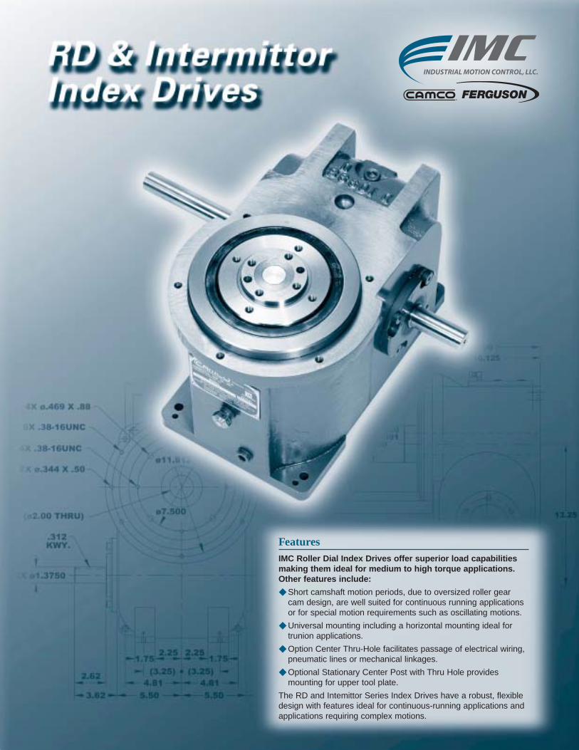
FeaturesIMC Roller Dial Index Drives offer superior load capabilitiesmaking them ideal for medium to high torque applications.Other features include:
◆ Short camshaft motion periods, due to oversized roller gearcam design, are well suited for continuous running applicationsor for special motion requirements such as oscillating motions.
◆ Universal mounting including a horizontal mounting ideal fortrunion applications.
◆ Option Center Thru-Hole facilitates passage of electrical wiring,pneumatic lines or mechanical linkages.
◆ Optional Stationary Center Post with Thru Hole provides mounting for upper tool plate.
The RD and Intemittor Series Index Drives have a robust, flexibledesign with features ideal for continuous-running applications andapplications requiring complex motions.

Industrial Motion Control, L.L.C. • www.camcoindex.com • (847) 459-5200
C
C-2
425RD
3.38
ø.8750
8.00
+.0005-.0000
4.250
6.12
2X ø.3125 X .38
2.31
2.25
4X ø.344
6.12
6.75
3.38
. .75
KWY..188
4X .312-18UNC
4X .312-18UNC
5X .312-18UNC
3.062.622X 30°
2X 40°
7.00
3.00 3.00
2.88
3.50
2X ø.219
( ) = OPTIONAL
.25
4.00
.62
8.50
7.88
-.0004+.0000
-.001
ø4.25
ø6.499
ø2.5000
+.000
8.50
4.00R
(ø.81)THRU
ø3.375
°
ø2.000
ø7.25
Technical SpecificationsOutput Load Capacity – loads carried during index
Radial 2,700 lbs
Thrust/Axial 1,600 lbs
Moment 5,800 in.-lbs
All dimensions are subject to change. For actual dimensions, please request the current drawing from IMC.
Accuracy ±47 arcsec / ±.0027" at 12" Radius
Repeatability ±12 arcsec / ±.0007" at 12" Radius
RD Index Drives
425RD Indexer Capacities
Other Motions (stops and index periods) available. Contact your lMC sales representative for more information.
Stops Index Motion B10 Capacity Internal Inertia Model (S) Period (β) at 50 RPM (in-lb) (lb-in2)2.0 300 ms 2,049 23 425RD2H32-300
3.0270 ms 2,536 23 425RD3H32-270180 ms 2,681 23 425RD3H32-180
4.0270 ms 2,899 25 425RD4H32-270180 ms 3,135 25 425RD4H32-180270 ms 2,652 23 425RD6H32-270
6.0180 ms 2,963 23 425RD6H32-180120 ms 3,166 23 425RD6H32-12090 ms 3,234 23 425RD6H32-90270 ms 2,999 25 425RD8H32-270
8.0180 ms 3,354 25 425RD8H32-180120 ms 3,648 25 425RD8H32-12090 ms 3,830 25 425RD8H32-90270 ms 2,300 22 425RD12H24-270
12.0180 ms 2,581 22 425RD12H24-180120 ms 2,871 22 425RD12H24-12090 ms 3,070 22 425RD12H24-90270 ms 4,101 25 425RD16H32-270 II
16.0 180 ms 4,622 25 425RD16H32-180 II120 ms 5,100 0 425RD16H32-120 II

Industrial Motion Control, L.L.C. • www.camcoindex.com • (847) 459-5200
C
C-3
1900 RPM, 90 VOLT D.C.1/3 HP MOTOR
IEC 71B14
ø 3.88
(FOR INITIAL SET-UP)REMOVABLE HANDWHEEL
2.005.87
ø
ø19MM
3.64
3.44
9.22
1.30
1.75 4.00
◆ R180 Reducer (ratios from 5:1 to 60:1)– Double Extended Worm Shaft (Input)– Worm Shaft Handwheel
◆ Double Extended Camshaft (Input Shaft)
Standard Package425RD Indexer with
◆ 1/3 hp DC Motor◆ Varipak DC Motor Control (up to 30 cpm)◆ Cycle Cam and Limit Switch Mounted to Camshaft◆ Right Hand Cam
2.8D OVERLOAD CLUCH
425RD MOUNTED ACCESSORIES RISER BLOCKS
AND LIMIT SWITCHCYCLE CAM
DIAL
TOOLING PLATE
Optional Accessories◆ 1/3 hp AC Drive Package with Inverter Duty Motor
and Inverter Drive (up to 60 cpm)◆ R225 Reducer with 1 hp AC or DC Motor
(ratios of 5:1 to 60:1)◆ 2.8D Output Overload Clutch
– Available Settings (in-lbs): 400, 480, 700, 850, 1100,1300, 1800, 2200, 3100
◆ Center Thru Hole (0.81 in. Diameter)◆ Stationary Center Post◆ Dual Cam and Limit Switch◆ Electric Clutch-Brake◆ 180IOC or 225IOC Input OLC◆ Left Hand Cam◆ Relief in Dwell for shot-pin applications◆ Universal Mounting Capability◆ Custom Dial Plate
All dimensions are subject to change. For actual dimensions, please request the current drawing from IMC.
All dimensions are subject to change. For actual dimensions, please request the current drawingfrom IMC.
RD Index Drives

Industrial Motion Control, L.L.C. • www.camcoindex.com • (847) 459-5200
C
C-4
800RD
ø4.250
ø7.500
ø11.812
18.25
2X 404 °
1.75
5.50
9.12
2X ø
KWY..312
9.12
5.50
4.814.81
2.25 2.251.75
4X ø.406
7.500
16.88
4.81
5X .375-16UNC
4X .500-20UNF
8X .375-16UNC2X ø.344
2X 30° 4.814.12
.56
2X ø.469 X 1.004.81
( ) = OPTIONAL 5.000
.75
13.25
10.12
11.50
+.0000-.0005
ø5.0000
+.000
ø10.6242
ø9.00
-.002
.188
(ø2.50 THRU)
Technical SpecificationsOutput Load Capacity – loads carried during index
Radial 4,900 lbs
Thrust/Axial 3,500 lbs
Moment 22,300 in.-lbs
All dimensions are subject to change. For actual dimensions, please request the current drawing from IMC.
Accuracy ±30 arcsec / ±.004" at 24" Radius
Repeatability ±8 arcsec / ±.0009" at 24" Radius
RD Index Drives
800RD Indexer Capacities
Other Motions (stops and index periods) available. Contact your lMC sales representative for more information.
Stops Index Motion B10 Capacity Internal Inertia Model (S) Period (β) at 50 RPM (in-lb) (lb-in2)2.0 270 msc.33 18,008 664 800RD2H64-270 MSC .33
3.0270 ms 18,653 664 800RD3H64-270180 ms 19,387 664 800RD3H64-180
4.0270 ms 22,261 714 800RD4H64-270180 ms 17,874 714 800RD4H56-180270 ms 19,416 664 800RD6H64-270
6.0 180 ms 21,422 664 800RD6H64-180120 ms 23,000 664 800RD6H64-120270 ms 22,016 714 800RD8H64-270
8.0 180 ms 24,499 714 800RD8H64-180120 ms 26,708 714 800RD8H64-120270 ms 13,394 639 800RD12H48-270
12.0 180 ms 15,016 639 800RD12H48-180120 ms 12,735 581 800RD12H40-120270 ms 30,320 664 800RD16H64-270 II
16.0 180 ms 33,885 664 800RD16H64-180 II120 ms 36,987 664 800RD16H64-120 II270 ms 18,205 639 800RD24H48-270 II
24.0 180 ms 20,610 639 800RD24H48-180 II120 ms 17,394 581 800RD24H40-120 II

Industrial Motion Control, L.L.C. • www.camcoindex.com • (847) 459-5200
C
C-5
(ø 1.000)
ø 1.9375
4.069.88
17.88
5.50
KWY..500
90V D.C. 1725 RPM1HP MOTOR
ø 6.62
ø 1.000
ø 5.25
( ) = OPTIONAL
(6.99)4.6
11.3
6.5
3.000
5.000
12.25
9.56
◆ 7300C Reducer (Ratios from 5:1 to 60:1)– Double Extended Worm Shaft (Input)– Motor Adapter and Coupling
◆ Double Extended Camshaft (Input Shaft)
Standard Package800RD Indexer with
◆ 1 hp DC Motor◆ Varipak DC Motor Control (up to 30 cpm)◆ Cycle Cam and Limit Switch Mounted to Camshaft◆ Right Hand Cam
Optional Accessories◆ 1 hp AC Drive Package with Inverter Duty Motor and
Inverter Drive (up to 60 cpm) [change]◆ 7350C Reducer (ratios from 5:1 to 60:1) with 1 hp
AC or DC Motor ◆ Output Overload Clutch model 7.8D
– Available Settings (in-lbs): 1400, 1700, 2600, 3200,4200, 5000, 7200, 10,000
◆ Output Overload Clutch model 18D– Available Settings (in-lbs): 5000, 7000, 7800,
10,000, 12,000, 16,000, 19,000, 21,000, 27,000,42,000, 45,000
◆ Center Thru Hole (2.50 in. Diameter)◆ Stationary Center Post◆ Dual Cam and Limit Switch◆ Electric Clutch-Brake◆ Air Clutch-Brake ◆ 300IOC or 350IOC Input OLC◆ Left Hand Cam◆ Relief in Dwell for shot-pin applications◆ Universal Mounting Capability◆ Custom Dial Plate
All dimensions are subject to change. For actual dimensions, please request the current drawing from IMC.
RD Index Drives
800RD MOUNTED ACCESSORIES
CUSTOMER SPECIFICATIONS)
7.80 OR 18D OVERLOAD CLUCH
STATIONARY CENTER POST
(CAMCO WILL ALTER TO
21.00
ø1.38 THRU
ø2.376
AND LIMIT SWITCH
RISER BLOCKS
CYCLE CAM
PLATETOOLING
DIAL
All dimensions are subject to change. For actual dimensions, please request the current drawingfrom IMC.

Industrial Motion Control, L.L.C. • www.camcoindex.com • (847) 459-5200
C
C-6
1301RD
KWY.
R9.88
17.75
( ) = OPTIONAL
16.50
40°
24.50
7.5015.00
12.25
40°
.375
2X ø1.6250
±.00510.500
6X .500-13UNC
8.008.44
30°
2X ø.438
(ø4.75 THRU)
30°
4X ø.812
5X .500-13UNC
ø13.75
5.75
12.50
26.38
-.00216.748ø
+.000
+
ø6.000-
.31 14.00
9.00
6.50 6.50
ø8.250
5.006.50
ø18.250
6.50
Technical SpecificationsOutput Load Capacity – loads carried during index
Radial 15,800 lbs
Thrust/Axial 10,800 lbs
Moment 109,000 in.-lbs
All dimensions are subject to change. For actual dimensions, please request the current drawing from IMC.
Accuracy ±39 arcsec / ±.0068" at 36" Radius
Repeatability ±10 arcsec / ±.0017" at 36" Radius
RD Index Drives
1301RD Indexer Capacities
Other Motions (stops and index periods) available. Contact your lMC sales representative for more information.
Stops Index Motion B10 Capacity Internal Inertia Model (S) Period (β) at 50 RPM (in-lb) (lb-in2)2.0 270 ms 19,022 1,987 1301RD2H64-2703.0 270 ms 27,856 2,094 1301RD3H64-2704.0 270 ms 32,613 2,094 1301RD4H64-270
6.0270 ms 37,310 2,094 1301RD6H64-270180 msc.33 45,088 2,094 1301RD6H64-180270 ms 31,686 1,987 1301RD8H56-270
8.0 180 ms 26,139 1,793 1301RD8H48-180120 ms 48,877 2,094 1301RD8H64-120270 ms 36,956 2,094 1301RD12H64-270
12.0 180 ms 41,200 2,094 1301RD12H64-180120 ms 45,113 2,094 1301RD12H64-120270 ms 31,015 1,987 1301RD16H56-270
16.0 180 ms 34,742 1,987 1301RD16H56-180120 ms 28,733 1,793 1301RD16H48-120270 ms 51,559 2,094 1301RD24H64-270 II
24.0 180 ms 57,777 2,094 1301RD24H64-180 II120 ms 63,438 2,094 1301RD24H64-120 II

Industrial Motion Control, L.L.C. • www.camcoindex.com • (847) 459-5200
C
C-7
ø2.4375
-.001ø1.1875
12.88
7.50 .75
4.62
10.56
ø6.62
+.000
16.50
ø7.00
7.55( ) = OPTIONAL
(ø1.1875)
-.0005+.0000
5.75
5.20
2 HP MOTOR180V DC 1725 RPM
(7.75)
20.38
◆ 7350C Reducer (Ratios from 5:1 to 60:1)– Double Extended Worm Shaft (Input)– Motor Adapter and Coupling
◆ Double Extended Camshaft (Input Shaft)
Standard Package1301RD Indexer with
◆ 2 hp DC Motor◆ Varipak DC Motor Control (up to 30 cpm)◆ Cycle Cam and Limit Switch Mounted to Camshaft◆ Right Hand Cam
31D OVERLOAD CLUTCH
STATIONARY CENTER POST(CAMCO WILL ALTER TOCUSTOMER SPECIFICATIONS)
1301RD MOUNTED ACCESSORIES RISER BLOCKS
AND LIMITSWITCH
CYCLE CAM
DIALTOOLINGPLATE
27.06
ø3.00 THRU
ø4.376
Optional Accessories◆ 2 hp AC Drive Package with Inverter Duty Motor and
Inverter Drive (up to 60 cpm) ◆ 7400C Reducer (Ratios from 5:1 to 60:1) with Motor
Adapter and Coupling◆ Output Overload Clutch model 31D
– Available Settings (in-lbs): 8500, 13,000, 20,000,31,000
◆ Center Thru Hole (4.75 in. Diameter)◆ Stationary Center Post◆ Dual Cam and Limit Switch◆ Electric Clutch-Brake◆ Air Clutch-Brake◆ 350IOC or 400IOC Input OLC◆ Left Hand Cam◆ Relief in Dwell for shot-pin applications◆ Universal Mounting Capability◆ Custom Dial Plate
All dimensions are subject to change. For actual dimensions, please request the current drawing from IMC.
All dimensions are subject to change. For actual dimensions, please request the current drawingfrom IMC.
RD Index Drives

Industrial Motion Control, L.L.C. • www.camcoindex.com • (847) 459-5200
C
C-8
1801RD
ø10.000
ø21.875
KWY.
2X ø2.6250
.625
16.00
32.00
11.07
10.00
11.07
17.88
10.00
15.75
8X .625-11UNC
6X .625-11UNC
(ø7.00)
9.34
12.25
14.81
17.13
2X ø.688
8X ø.688
THRU
19.16
12.75
4.00
8X .625-11UNC
20.2221.75
1.75
( ) = OPTIONAL
6.00
4.00
4.00
4.00
-.001+.000
ø8.000
ø20.750
11.0910.31
ø14.50
-.002+.000
R11.88
.69
13.000
32.88
11.88
All dimensions are subject to change. For actual dimensions, please request the current drawing from IMC.
Technical SpecificationsOutput Load Capacity – loads carried during index
Radial 14,800 lbs
Thrust/Axial 12,600 lbs
Moment 107,000 in.-lbs
Accuracy ±27 arcsec / ±.0063" at 48" Radius
Repeatability ±7 arcsec / ±.0016" at 48" Radius
RD Index Drives
1801RD Indexer Capacities
Other Motions (stops and index periods) available. Contact your lMC sales representative for more information.
Stops Index Motion B10 Capacity Internal Inertia Model (S) Period (β) at 50 RPM (in-lb) (lb-in2)2.0 330 msc.67 50,905 6,718 1801RD2H64-330 MSC .673.0 270 msc.33 48,963 6,718 1801RD3H64-270 MSC .33
4.0270 ms 40,633 6,718 1801RD4H64-270180 msc.50 57,344 6,718 1801RD4H64-180 MSC .50270 ms 92,427 7,672 1801RD6H80-270
6.0 180 msc.50 120,548 7,672 1801RD6H80-180 MSC .50120 msc.50 90,444 6,718 1801RD6H64-120 MSC .50270 ms 66,038 7,090 1801RD8H64-270
8.0 180 msc.33 80,281 7,090 1801RD8H64-180 MSC .33120 msc.33 61,376 6,222 1801RD8H56-120 MSC .33270 ms 125,722 8,963 1801RD12H96-270
12.0 180 ms 141,136 8,963 1801RD12H96-180120 ms 112,949 7,672 1801RD12H80-120270 ms 94,125 8,371 1801RD16H80-270
16.0 180 msc.33 118,052 7,090 1801RD16H80-180 MSC .33120 ms 80,638 7,090 1801RD16H64-120270 ms 170,392 8,963 1801RD24H96-270 II
24.0 180 ms 191,240 8,963 1801RD24H96-180 II120 ms 141,038 7,672 1801RD24H80-120 II

Industrial Motion Control, L.L.C. • www.camcoindex.com • (847) 459-5200
C
C-9
(ø1.500)
6.2517.50
10.00
24.75
ø8.13
ø1.500
13.69
5.65( ) = OPTIONAL
(10.50)
17.95
5.00
ø2.7500
1.00
7.00
10.50
19.75
+.000-.001
180V DC 1725 RPM3HP MOTOR
◆ 7500C Reducer (Ratios from 5:1 to 60:1)– Double Extended Worm Shaft (Input)– Motor Adapter and Coupling
◆ Double Extended Camshaft (Input Shaft)
Standard Package1801RD Indexer with
◆ 3 hp DC Motor◆ Cycle Cam and Limit Switch Mounted to Camshaft◆ Right Hand Cam
1801RD MOUNTED ACCESSORIES
STATIONARY CENTER POST
62D OVERLOAD CLUTCH
ø5.00 THRU
21.00
4X .375-16UNC
ø
ø6.95
-.001
RISER BLOCKS
AND LIMIT SWITCHCYCLE CAM
DIAL
TOOLINGPLATE
ø12.312
Optional Accessories◆ 3 hp AC Drive Package with Inverter Duty Motor and
Inverter Drive (up to 60 cpm) ◆ 7600C or 7700C Reducer (Ratios from 5:1 to 60:1)
with Motor Adapter and Coupling◆ Output Overload Clutch model 62D
– Available Settings (in-lbs): 23,000, 36,000, 44,000,50,000, 60,000
◆ Center Thru Hole (7.00 in. Diameter)◆ Stationary Center Post◆ Dual Cam and Limit Switch◆ Electric Clutch-Brake ◆ Air Clutch-Brake◆ 500IOC, 600IOC or 700IOC Input OLC◆ Left Hand Cam◆ Relief in Dwell for shot-pin applications ◆ Custom Dial Plate
All dimensions are subject to change. For actual dimensions, please request the current drawing from IMC.
All dimensions are subject to change. For actual dimensions, please request the current drawingfrom IMC.
RD Index Drives
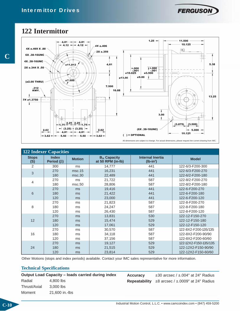
Industrial Motion Control, L.L.C. • www.camcoindex.com • (847) 459-5200
C
C-10
122 Intermittor
.312KWY.
6X .38-16UNC
(ø2.00 THRU)
4X .38-16UNC
2X ø.344 X .50
4X ø.469 X .882X ø.359
4X ø.406
(6X .38-16UNC)
( ) = OPTIONAL
+.000-.001+.000
-.001
ø13.00
16.88
7.500
3.62
2.62
2X ø1.3750
5.50 5.50
(3.25)
4.81
2.251.75
(3.25)
4.81
1.75
3.62
2.62
ø7.500
ø11.812 4.81
4.12
4.81 4.81
(3.875)
3.00
(3.500)
5.000
10.125
13.25
11.500
øø
ø9.00
1.25
5.38
Technical SpecificationsOutput Load Capacity – loads carried during index
Radial 4,800 lbs
Thrust/Axial 3,000 lbs
Moment 21,600 in.-lbs
All dimensions are subject to change. For actual dimensions, please request the current drawing from IMC.
Accuracy ±30 arcsec / ±.004" at 24" Radius
Repeatability ±8 arcsec / ±.0009" at 24" Radius
Intermittor Drives
122 Indexer Capacities
Other Motions (stops and index periods) available. Contact your lMC sales representative for more information.
Stops Index Motion B10 Capacity Internal Inertia Model (S) Period (β) at 50 RPM (in-lb) (lb-in2)2 300 ms 14,777 441 122-6/3-F200-300
3270 msc.15 16,231 441 122-6/3-F200-270180 msc.30 22,489 441 122-6/2-F200-180
4270 ms 21,722 587 122-8/2-F200-270180 msc.50 28,806 587 122-8/2-F200-180270 ms 19,416 441 122-6-F200-270
6 180 ms 21,422 441 122-6-F200-180120 ms 23,000 441 122-6-F200-120270 ms 21,823 587 122-8-F200-270
8 180 ms 24,247 587 122-8-F200-180120 ms 26,430 587 122-8-F200-120270 ms 13,831 530 122-12-F150-270
12 180 ms 15,474 529 122-12-F150-180120 ms 17,061 529 122-12-F150-120270 ms 30,570 587 122-8X2-F200-135/135
16 180 ms 34,118 587 122-8X2-F200-90/90120 ms 37,156 587 122-8X2-F200-60/60270 ms 19,127 529 122-12X2-F150-135/135
24 180 ms 21,515 529 122-12X2-F150-90/90120 ms 23,814 529 122-12X2-F150-60/60
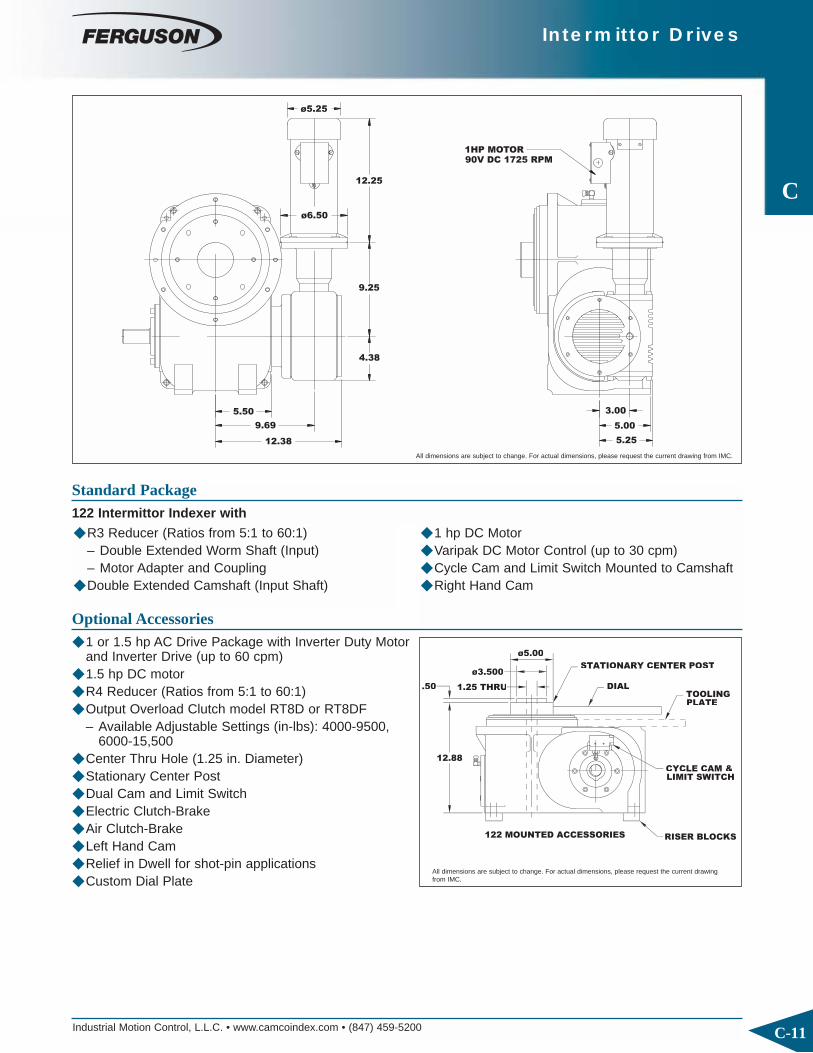
Industrial Motion Control, L.L.C. • www.camcoindex.com • (847) 459-5200
C
C-11
3.00
5.00
5.25
12.25
ø5.25
9.25
4.38
12.38
5.50
9.69
ø6.50
1HP MOTOR90V DC 1725 RPM
◆ R3 Reducer (Ratios from 5:1 to 60:1)– Double Extended Worm Shaft (Input)– Motor Adapter and Coupling
◆ Double Extended Camshaft (Input Shaft)
Standard Package122 Intermittor Indexer with
◆ 1 hp DC Motor◆ Varipak DC Motor Control (up to 30 cpm)◆ Cycle Cam and Limit Switch Mounted to Camshaft◆ Right Hand Cam
.50 1.25 THRUU
ø3.500
ø5.00
122 MOUNTED ACCESSORIES RISER BLOCKS
STATIONARY CENTER POST
DIAL
PLATETOOLING
CYCLE CAM &LIMIT SWITCH
Optional Accessories◆ 1 or 1.5 hp AC Drive Package with Inverter Duty Motor
and Inverter Drive (up to 60 cpm) ◆ 1.5 hp DC motor◆ R4 Reducer (Ratios from 5:1 to 60:1)◆ Output Overload Clutch model RT8D or RT8DF
– Available Adjustable Settings (in-lbs): 4000-9500,6000-15,500
◆ Center Thru Hole (1.25 in. Diameter)◆ Stationary Center Post◆ Dual Cam and Limit Switch◆ Electric Clutch-Brake ◆ Air Clutch-Brake◆ Left Hand Cam◆ Relief in Dwell for shot-pin applications ◆ Custom Dial Plate
All dimensions are subject to change. For actual dimensions, please request the current drawing from IMC.
All dimensions are subject to change. For actual dimensions, please request the current drawingfrom IMC.
Intermittor Drives

Industrial Motion Control, L.L.C. • www.camcoindex.com • (847) 459-5200
C
C-12
Intermittor Drives
242 Intermittor
8.31
16.382X ø
7.50 7.50
5.81
6.62
3.00
5.81
6.62
3.00
15.56
10.500
7.696.97
5.69
4.75
6.56
(4.88)
6.50
(4.25)
5.750
12.1251 5
17.75
ø10.00ø17.00
ø14.625ø6.250
.31 14.000
( ) = OPTIONAL
4X .38-16UNC
6X .50-13UNC
4X ø.469 X 1.00
2X ø.469
ø
ø.531
ø.469
(6X .75-10UNC)
-.001+.000
+.000-.001
9.00
ø8.250
Technical SpecificationsOutput Load Capacity – loads carried during index
Radial 6,800 lbs
Thrust/Axial 4,700 lbs
Moment 40,600 in.-lbs
All dimensions are subject to change. For actual dimensions, please request the current drawing from IMC.
Accuracy ±39 arcsec / ±.0068" at 36" Radius
Repeatability ±10 arcsec / ±.0017" at 36" Radius
242 Indexer Capacities
Other Motions (stops and index periods) available. Contact your lMC sales representative for more information.
Stops Index Motion B10 Capacity Internal Inertia Model (S) Period (β) at 50 RPM (in-lb) (lb-in2)2 330 msc.50 42,334 2,083 242-6/3-F250-3303 300 msc.30 32,163 2,083 242-12/4-F200-300
4300 ms 31,968 2,083 242-12/3-F200-300180 msc.15 27,356 1,882 242-12/3-F175-180270 ms 37,947 2,083 242-12/2-F200-270
6 180 msc.15 43,151 2,083 242-12/2-F200-180120 msc.30 35,799 1,882 242-12/2-F175-120270 ms 31,997 1,951 242-16/2-F175-270
8 180 msc.15 36,569 1,951 242-16/2-F175-180120 msc.15 27,741 1,801 242-16/2-F150-120270 ms 37,347 2,083 242-12-F200-270
12180 ms 41,710 2,083 242-12-F200-180120 ms 45,893 2,083 242-12-F200-12090 ms 48,340 2,083 242-12-F200-90270 ms 31,733 1,951 242-16-F175-270
16 180 ms 35,510 1,951 242-16-F175-180120 ms 39,193 1,951 242-16-F175-120270 ms 51,566 2,083 242-12X2-F200-135/135
24 180 ms 57,376 2,083 242-12X2-F200-90/90120 ms 62,484 2,083 242-12X2-F200-60/60

Industrial Motion Control, L.L.C. • www.camcoindex.com • (847) 459-5200
C
C-13
Intermittor Drives
13.87
9.75
(9.31)
10.443.82
(ø1.500)
5.75
ø6.62
ø7.75
5.00( ) = OPTIONAL 6.88
4.00
180V DC 1725 RPM1.5HP MOTOR
◆ R4 Reducer (Ratios from 5:1 to 60:1)– Double Extended Worm Shaft (Input)– Motor Adapter and Coupling
◆ Double Extended Camshaft (Input Shaft)
Standard Package242 Intermittor Indexer with
◆ 1.5 hp DC Motor◆ Varipak DC Motor Control (up to 30 cpm)◆ Cycle Cam and Limit Switch Mounted to Camshaft◆ Right Hand Cam
242 MOUNTED ACCESORIES
15.62
ø
ø
ø2.00 THRU
.75 4.50
RISER BLOCKS
LIMIT SWITCHCYCLE CAM &
PLATETOOLING
STATIONARY CENTER POST
DIAL
Optional Accessories◆ 1.5 or 2 hp AC Drive Package with Inverter Duty Motor
and Inverter Drive (up to 60 cpm) ◆ 2 hp DC motor◆ R5 Reducer (Ratios from 5:1 to 60:1) with Motor
Adapter and Coupling◆ Center Thru Hole (2.00 in. Diameter)◆ Stationary Center Post◆ Dual Cam and Limit Switch◆ Electric Clutch-Brake ◆ Air Clutch-Brake◆ R4 or R5 FSC Input OLC◆ Left Hand Cam◆ Relief in Dwell for shot-pin applications ◆ Custom Dial Plate
All dimensions are subject to change. For actual dimensions, please request the current drawing from IMC.
All dimensions are subject to change. For actual dimensions, please request the current drawingfrom IMC.

Industrial Motion Control, L.L.C. • www.camcoindex.com • (847) 459-5200
C
C-14
1. Model
2. Input Shaft Configuration◆ Side 1◆ Side 2◆ Double Input – DI (Standard)
1. Model
2. Ratio◆ 5:1, 10:1, 15:1, 20:1, 25:1, 30:1, 40:1, 50:1, 60:1
3. Motor Adapter
4. Reducer Input Shaft Extension◆ Single Input (SE) or Double Input (DE)
Indexer Ordering Procedure3. Cam Lead (Helix)
◆ Right Hand (Standard)◆ Left Hand
NOTE: Input may rotate in either direction to achievedesired direction of output rotation.
4. Indexer Mounting Position: 1-6
Reducer Ordering Procedure5. Mounting
◆ Mounting Position A, B, C, or D◆ Mounted on Indexer Side 1 or Side 2
6. Input Shaft Orientation◆ Left or Right (See Diagram Below)
* Consult IMC for availability of this mounting
RD & Intermittor Drives
AS(Standard)
AE
Cam Lead
Right Hand
AE: Input Shaft
Left Hand
AS
5
AE
AS: Output Shaft
AS
6AE
AE
AS
AE
Indexer Mounting PositionPosition of Shafts
2Double Input (DI)
1
Input
3
1AS
AS
4
2
HLH B-2-LH LHA-2-RH
RH
Reducer Mounting Position
B-1-RH A-1-LH RH
D-2
1-RH
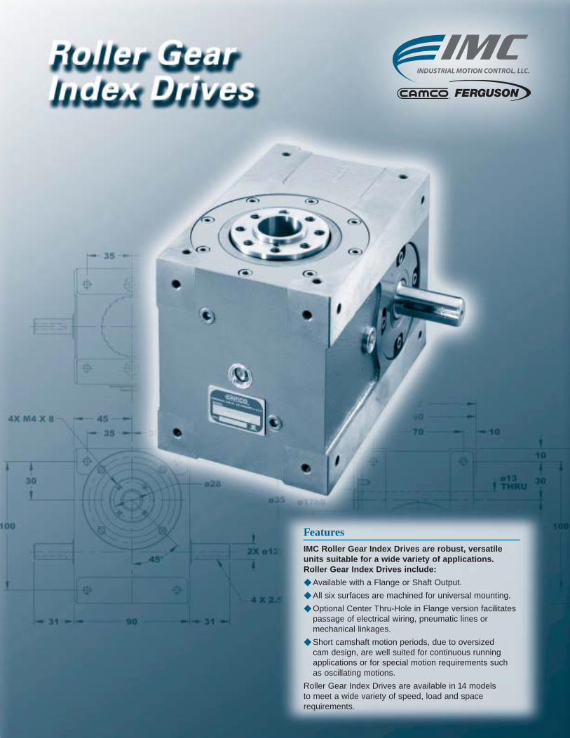
FeaturesIMC Roller Gear Index Drives are robust, versatileunits suitable for a wide variety of applications.Roller Gear Index Drives include:
◆ Available with a Flange or Shaft Output.
◆ All six surfaces are machined for universal mounting.
◆ Optional Center Thru-Hole in Flange version facilitatespassage of electrical wiring, pneumatic lines ormechanical linkages.
◆ Short camshaft motion periods, due to oversized cam design, are well suited for continuous runningapplications or for special motion requirements such as oscillating motions.
Roller Gear Index Drives are available in 14 models to meet a wide variety of speed, load and space requirements.

Industrial Motion Control, L.L.C. • www.camcoindex.com • (847) 459-5200D-2
Roller Gear Index Drives
D
31
30
100
4X M4 X 8
90 31 8X M6 X 12
4 X 2.5 N9
45
45 8X M6 X 12
°
35 35
ø17h8
2X ø12h6
ø35
8X M6 X 1235 35
32.5
3
32.5
90
ø13
40
120
92
ALL DIMENSIONS = MILLIMETERS
ø28
70 10
30
100
10
40RGD/40RGSAll dimensions are subject to change. For actual dimensions, please request the current drawing from IMC.
40RGD/RGS Indexer CapacitiesStops Index Motion B10 Capacity RGD Internal RGS Internal Model*
(S) Period (β) at 50 RPM (in-lb) Inertia (lb-in2) Inertia (lb-in2)2 270 ms 150 0.3 0.4 40RG(D/S)2H12-2703 270 ms 187 0.3 0.4 40RG(D/S)3H12-270
4270 ms 214 0.4 0.4 40RG(D/S)4H12-270180 ms 225 0.4 0.4 40RG(D/S)4H12-180270 ms 193 0.3 0.4 40RG(D/S)6H12-270
6180 ms 208 0.3 0.4 40RG(D/S)6H12-180120 ms 220 0.3 0.4 40RG(D/S)6H12-12090 ms 216 0.3 0.4 40RG(D/S)6H12-90270 ms 216 0.4 0.4 40RG(D/S)8H12-270
8180 ms 243 0.4 0.4 40RG(D/S)8H12-180120 ms 250 0.4 0.4 40RG(D/S)8H12-12090 ms 249 0.4 0.4 40RG(D/S)8H12-90270 ms 124 0.3 0.4 40RG(D/S)12H9-270
12180 ms 140 0.3 0.4 40RG(D/S)12H9-180120 ms 139 0.3 0.4 40RG(D/S)12H9-12090 ms 139 0.3 0.4 40RG(D/S)12H9-90
16270 ms 254 0.4 0.4 40RG(D/S)16H12-270 II120 ms 312 0.4 0.4 40RG(D/S)16H12-120 II
24180 ms 173 0.3 0.4 40RG(D/S)24H9-180 II120 ms 326 0.3 0.4 40RG(D/S)24H12-120 III
40RGD
Technical SpecificationsOutput Load Capacity – loads carried during index
RGD RGSRadial 1107 lbs 374 lbsThrust/Axial 791 lbs 492 lbsMoment 762 in-lbs 736 in-lbs
Accuracy ±90 arcsec / ±.0013" at 3" Radius
Repeatability ±45 arcsec / ±.0007" at 3" Radius
* Specify “D” for Dial (Flange) Output or “S” for Shaft Output.Other Motions (stops and index periods) available. Contact your lMC sales representative for more information.

Industrial Motion Control, L.L.C. • www.camcoindex.com • (847) 459-5200 D-3
Roller Gear Index Drives
D
31
30
100
90 318X M6 X 12
4 X 2.5 N9
( ) = OPTIONAL
40
ø12 h6
ø16h6
5 X 3 N9
8X M6 X 1235 35
8X M6 X 1235 35
32.5
32.5
90 (40)
(ø16h6)
120
40
70 10
30
100
10
ALL DIMENSIONS = MILLIMETERS
Standard Features◆ Fully Metric◆ Universal Mounting: mounting holes on any of
6 sides
IEC 63B14 MOTOR ADAPTOR
ø14
1/5 HP D.C. MOTOR1800 RPM, 90 VOLTTENV
ø90
ø86
( ) = OPTIONAL(ø9)
181
3264 37 20
(65)
51
40
ALL DIMENSIONS = MILLIMETERS
SW-030-FA GEAR REDUCER
Accessories and Options◆ SW-030 Gear Reducer (ratios from 5:1 to 50:1) with
– IEC63B14 Motor Adapter– 1/5 hp DC Motor and Varipak DC Motor Control
(up to 30 cpm)– 1/6 hp AC Motor and Inverter Drive (up to 60 cpm)
◆ .06 hp DC Gear Motor Drive Package– Direct Drive or Belt Drive– Varipak DC Motor Control (up to 30 cpm)
All dimensions are subject to change. For actual dimensions, please request the current drawing from IMC.
All dimensions are subject to change. For actual dimensions,please request the current drawing from IMC.
◆ Center Through Hole (.50 in./13 mm Diameter)in RGD model.
◆ Right Hand Cam
◆ Output Overload Clutch Models: M40F, M40FC,M40S and M40C– Available Settings: 160, 210, 270 in-lb or
18, 24, 30 Nm◆ Single or Dual Cycle Cam and Limit Switch◆ Left Hand Cam◆ Relief in Dwell for shot-pin applications
40RGS
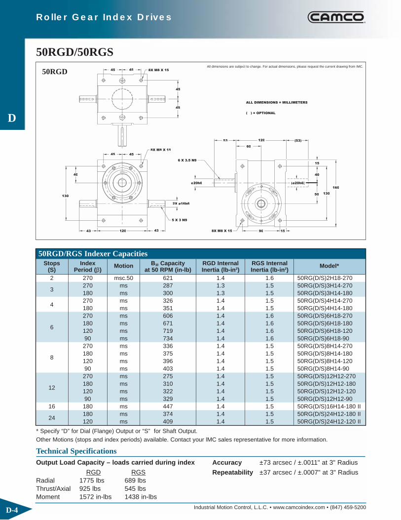
Industrial Motion Control, L.L.C. • www.camcoindex.com • (847) 459-5200D-4
Roller Gear Index Drives
D
50RGD/50RGS45
130
40
43 120
45 45
( ) = OPTIONAL
(ø20h6)
60
120 (53)
ø20h6
6 X 3.5 N9
2X ø16h6
5 X 3 N9
53
43
8X M8 X 15
8X M8 X 15
160
50
8X M8 X 15
45
45
ALL DIMENSIONS = MILLIMETERS
40
15
130
90 15
All dimensions are subject to change. For actual dimensions, please request the current drawing from IMC.
50RGD/RGS Indexer CapacitiesStops Index Motion B10 Capacity RGD Internal RGS Internal Model*
(S) Period (β) at 50 RPM (in-lb) Inertia (lb-in2) Inertia (lb-in2)2 270 msc.50 621 1.4 1.6 50RG(D/S)2H18-270
3270 ms 287 1.3 1.5 50RG(D/S)3H14-270180 ms 300 1.3 1.5 50RG(D/S)3H14-180
4270 ms 326 1.4 1.5 50RG(D/S)4H14-270180 ms 351 1.4 1.5 50RG(D/S)4H14-180270 ms 606 1.4 1.6 50RG(D/S)6H18-270
6180 ms 671 1.4 1.6 50RG(D/S)6H18-180120 ms 719 1.4 1.6 50RG(D/S)6H18-12090 ms 734 1.4 1.6 50RG(D/S)6H18-90270 ms 336 1.4 1.5 50RG(D/S)8H14-270
8180 ms 375 1.4 1.5 50RG(D/S)8H14-180120 ms 396 1.4 1.5 50RG(D/S)8H14-12090 ms 403 1.4 1.5 50RG(D/S)8H14-90270 ms 275 1.4 1.5 50RG(D/S)12H12-270
12180 ms 310 1.4 1.5 50RG(D/S)12H12-180120 ms 322 1.4 1.5 50RG(D/S)12H12-12090 ms 329 1.4 1.5 50RG(D/S)12H12-90
16 180 ms 447 1.4 1.5 50RG(D/S)16H14-180 II
24180 ms 374 1.4 1.5 50RG(D/S)24H12-180 II120 ms 409 1.4 1.5 50RG(D/S)24H12-120 II
50RGD
Technical SpecificationsOutput Load Capacity – loads carried during index
RGD RGSRadial 1775 lbs 689 lbsThrust/Axial 925 lbs 545 lbsMoment 1572 in-lbs 1438 in-lbs
Accuracy ±73 arcsec / ±.0011" at 3" Radius
Repeatability ±37 arcsec / ±.0007" at 3" Radius
* Specify “D” for Dial (Flange) Output or “S” for Shaft Output.Other Motions (stops and index periods) available. Contact your lMC sales representative for more information.

Industrial Motion Control, L.L.C. • www.camcoindex.com • (847) 459-5200 D-5
Roller Gear Index Drives
D
45
130
40
43 120
45 45
( ) = OPTIONAL
(ø20h6)
60
120 (53)
ø20h6
6 X 3.5 N9
2X ø16h6
5 X 3 N9
53
43
8X M8 X 15
8X M8 X 15
160
50
8X M8 X 15
45
45
ALL DIMENSIONS = MILLIMETERS
40
15
130
90 15
Standard Features◆ Fully Metric◆ Universal Mounting: mounting holes on any of
6 sides
MOTOR ADAPTORIEC 63B14
( ) = OPTIONAL
ø90
1/5 HP D.C. MOTOR
TENV1800 RPM, 90 VOLT
3979
(ø11)
4043 23
(76)
50
ø19
70
181
ALL DIMENSIONS = MILLIMETERS
GEAR REDUCERSW-040-FA
Accessories and Options◆ SW-040 Gear Reducer (ratios from 5:1 to 40:1) with
– IEC63B14 Motor Adapter– 1/4 hp AC Motor and Inverter Drive (up to 60 cpm)– 1/5 hp DC Motor and Varipak DC Motor Control
(up to 30 cpm)◆ .125 hp DC Gear Motor Drive Package
– Direct Drive or Belt Drive– Varipak DC Motor Control (up to 30 cpm)
All dimensions are subject to change. For actual dimensions, please request the current drawing from IMC.
All dimensions are subject to change. For actual dimensions,please request the current drawing from IMC.
◆ Center Through Hole (.59 in. / 15 mm Diameter) in RGD model.
◆ Right Hand Cam
◆ Output Overload Clutch Models: M50F, M50FC, M50S and M50C– Available Settings: 270, 320, 390 in-lb or 30,
35, 40 Nm◆ Single or Dual Cycle Cam and Limit Switch◆ Left Hand Cam◆ Relief in Dwell for shot-pin applications
50RGS

Industrial Motion Control, L.L.C. • www.camcoindex.com • (847) 459-5200D-6
Roller Gear Index Drives
D
70RGD/RGS Indexer CapacitiesStops Index Motion B10 Capacity RGD Internal RGS Internal Model*
(S) Period (β) at 50 RPM (in-lb) Inertia (lb-in2) Inertia (lb-in2)
2270 ms 585 7 8 70RG(D/S)2H20-270180 ms 562 7 8 70RG(D/S)2H18-180
3270 ms 720 7 8 70RG(D/S)3H20-270180 ms 753 7 8 70RG(D/S)3H20-180270 ms 821 9 10 70RG(D/S)4H20-270
4 180 msc.15 942 9 10 70RG(D/S)4H20-180120 msc.33 1107 10 10 70RG(D/S)4H18-120270 ms 1406 9 10 70RG(D/S)6H24-270
6180 ms 1583 9 10 70RG(D/S)6H24-180120 ms 1768 9 10 70RG(D/S)6H24-12090 msc.33 2110 9 10 70RG(D/S)6H24-90270 ms 853 9 10 70RG(D/S)8H20-270
8180 ms 949 9 10 70RG(D/S)8H20-180120 ms 1027 9 10 70RG(D/S)8H20-12090 ms 1063 9 10 70RG(D/S)8H20-90270 ms 470 10 10 70RG(D/S)12H14-270
12180 ms 528 10 10 70RG(D/S)12H14-180120 ms 564 10 10 70RG(D/S)12H14-12090 ms 584 10 10 70RG(D/S)12H14-90
24 180 ms 635 10 10 70RG(D/S)24H14-180 II
THRU55ø120h7
6 X 3.5 N9
50
2X ø20h6
130
65
50
60
15
70 195
165
50
8X M10 X 20
100
15
5050
6X M6 X 12
15100 8X M10 X 20
8X M10 X 20 100
ø65 ø35 h6
15
15
165
ø19
10
8
130
65
150
ALL DIMENSIONS = MILLIMETERS
70RGD/70RGS
70RGD
Technical SpecificationsOutput Load Capacity – loads carried during index
RGD RGSRadial 2833 lbs 1019 lbsThrust/Axial 2224 lbs 802 lbsMoment 3626 in-lbs 2808 in-lbs
Accuracy ±50 arcsec / ±.0008" at 3" Radius
Repeatability ±25 arcsec / ±.0003" at 3" Radius
* Specify “D” for Dial (Flange) Output or “S” for Shaft Output.Other Motions (stops and index periods) available. Contact your lMC sales representative for more information.
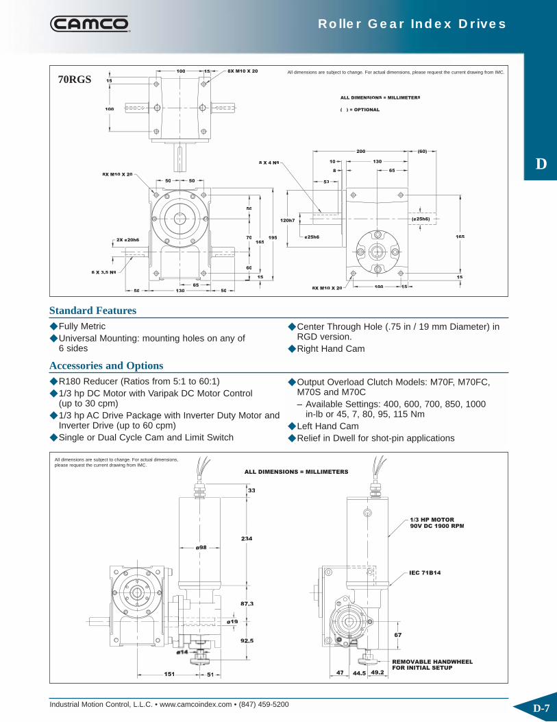
Industrial Motion Control, L.L.C. • www.camcoindex.com • (847) 459-5200 D-7
Roller Gear Index Drives
D50
100
15
8X M10 X 20
50
2X ø20h6
6 X 3.5 N9
( ) = OPTIONAL
50
195
60
70 ø25h6165
15
100
50
130
65
(ø25h6)
8X M10 X 20
8X M10 X 20
165
15
200
13010
8
53
65
(60)
15
8 X 4 N9
50
120h7
100 15
ALL DIMENSIONS = MILLIMETERS
Standard Features◆ Fully Metric◆ Universal Mounting: mounting holes on any of
6 sides
151
92.5
51
87.3
ø19
ø98
67
47
234
33
REMOVABLE HANDWHEELFOR INITIAL SETUP
IEC 71B14
90V DC 1900 RPM1/3 HP MOTOR
ALL DIMENSIONS = MILLIMETERS
Accessories and Options◆ R180 Reducer (Ratios from 5:1 to 60:1)◆ 1/3 hp DC Motor with Varipak DC Motor Control
(up to 30 cpm)◆ 1/3 hp AC Drive Package with Inverter Duty Motor and
Inverter Drive (up to 60 cpm) ◆ Single or Dual Cycle Cam and Limit Switch
All dimensions are subject to change. For actual dimensions, please request the current drawing from IMC.
All dimensions are subject to change. For actual dimensions,please request the current drawing from IMC.
◆ Center Through Hole (.75 in / 19 mm Diameter) in RGD version.
◆ Right Hand Cam
◆ Output Overload Clutch Models: M70F, M70FC, M70S and M70C– Available Settings: 400, 600, 700, 850, 1000
in-lb or 45, 7, 80, 95, 115 Nm◆ Left Hand Cam◆ Relief in Dwell for shot-pin applications
70RGS
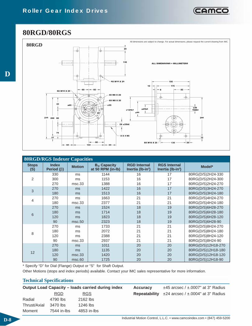
Industrial Motion Control, L.L.C. • www.camcoindex.com • (847) 459-5200D-8
Roller Gear Index Drives
D
THRU
235
75
15
80200
8X M10 X 20
60
ø125h7 45h6
ø80°
8 X 4 N9
8X M10 X 20 130
4X M8 X 20
8X M10 X 20
6X M8 X 20
130
20
10 170
195
82
ø26
20
15
200
60
60 160
ø65
60
80
60
2X ø25h6
ø55
ALL DIMENSIONS = MILLIMETERS
80RGD/80RGSAll dimensions are subject to change. For actual dimensions, please request the current drawing from IMC.
80RGD/RGS Indexer CapacitiesStops Index Motion B10 Capacity RGD Internal RGS Internal Model*
(S) Period (β) at 50 RPM (in-lb) Inertia (lb-in2) Inertia (lb-in2)330 ms 1144 16 17 80RG(D/S)2H24-330
2 300 ms 1153 16 17 80RG(D/S)2H24-300270 msc.33 1388 16 17 80RG(D/S)2H24-270
3270 ms 1422 16 17 80RG(D/S)3H24-270180 ms 1513 16 17 80RG(D/S)3H24-180
4270 ms 1663 21 21 80RG(D/S)4H24-270180 msc.33 2377 21 21 80RG(D/S)4H24-180270 ms 1524 18 19 80RG(D/S)6H28-270
6180 ms 1714 18 19 80RG(D/S)6H28-180120 ms 1823 18 19 80RG(D/S)6H28-12090 msc.50 2323 18 19 80RG(D/S)6H28-90270 ms 1733 21 21 80RG(D/S)8H24-270
8180 ms 2072 21 21 80RG(D/S)8H24-180120 ms 2388 21 21 80RG(D/S)8H24-12090 msc.33 2937 21 21 80RG(D/S)8H24-90270 ms 1011 20 20 80RG(D/S)12H18-270
12180 ms 1135 20 20 80RG(D/S)12H18-180120 msc.33 1420 20 20 80RG(D/S)12H18-12090 msc.60 1725 20 20 80RG(D/S)12H18-90
80RGD
Technical SpecificationsOutput Load Capacity – loads carried during index
RGD RGSRadial 4790 lbs 2162 lbsThrust/Axial 3470 lbs 1246 lbsMoment 7544 in-lbs 4853 in-lbs
Accuracy ±45 arcsec / ±.0007" at 3" Radius
Repeatability ±24 arcsec / ±.0004" at 3" Radius
* Specify “D” for Dial (Flange) Output or “S” for Shaft Output.Other Motions (stops and index periods) available. Contact your lMC sales representative for more information.
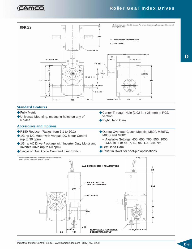
Industrial Motion Control, L.L.C. • www.camcoindex.com • (847) 459-5200 D-9
Roller Gear Index Drives
D
8 X 4 N9
30h6
8 X 4 N9
60
15
75
235 200 80
60
160
80
60
ø80
4X M8 X 16
8X M10 X 20
8X M10 X 20
20
130
(ø30h6)
8X M10 X 20 20130
15
200
( ) = OPTIONAL
57
52
170
232
80.5
(57)
ø25h6
60 60
ALL DIMENSIONS = MILLIMETERS
Standard Features◆ Fully Metric◆ Universal Mounting: mounting holes on any of
6 sides
FOR INITIAL SETUPREMOVABLE HANDWHEEL
80
44,5 82
ø98
IEC 71B14
90V DC 1900 RPM1/3 H.P. MOTOR
176
63
114
ø14
ø19
234
92
87
33
ALL DIMENSIONS = MILLIMETERS
Accessories and Options◆ R180 Reducer (Ratios from 5:1 to 60:1)◆ 1/3 hp DC Motor with Varipak DC Motor Control
(up to 30 cpm)◆ 1/3 hp AC Drive Package with Inverter Duty Motor and
Inverter Drive (up to 60 cpm) ◆ Single or Dual Cycle Cam and Limit Switch
All dimensions are subject to change. For actual dimensions,please request the current drawing from IMC.
◆ Center Through Hole (1.02 in. / 26 mm) in RGD version.
◆ Right Hand Cam
◆ Output Overload Clutch Models: M80F, M80FC, M80S and M80C– Available Settings: 400, 600, 700, 850, 1000,
1300 in-lb or 45, 7, 80, 95, 115, 145 Nm◆ Left Hand Cam◆ Relief in Dwell for shot-pin applications
80RGSAll dimensions are subject to change. For actual dimensions, please request the currentdrawing from IMC.

Industrial Motion Control, L.L.C. • www.camcoindex.com • (847) 459-5200D-10
Roller Gear Index Drives
D
70
8X M10 X 20
24
89
292
245110
70
8 X 4 N9
8X M12 X 25
2X ø
67
70
320
186
93
ø90 H6
8X M10 X 20(23)
ø100ø55
160 24
ø
245
67
5
160
24
212
208
10
101
8X M10 X 20
ALL DIMENSIONS = MILLIMETERS
110RGD/110RGSAll dimensions are subject to change. For actual dimensions, please request the current drawing from IMC.
110RGD
110RGD/RGS Indexer CapacitiesStops Index Motion B10 Capacity RGD Internal RGS Internal Model*
(S) Period (β) at 50 RPM (in-lb) Inertia (lb-in2) Inertia (lb-in2)
2300 msc.33 5271 51 56 110RG(D/S)2H40-300270 msc.50 6126 51 56 110RG(D/S)2H40-270
3270 ms 5609 51 56 110RG(D/S)3H40-270180 msc.50 7829 51 56 110RG(D/S)3H40-180
4270 ms 3282 48 55 110RG(D/S)4H32-270180 msc.33 4147 48 55 110RG(D/S)4H32-180270 ms 7378 52 70 110RG(D/S)6H48-270
6 180 msc.33 9342 52 70 110RG(D/S)6H48-180120 msc.33 8127 51 56 110RG(D/S)6H40-120270 ms 3440 48 55 110RG(D/S)8H32-270
8 180 ms 3823 48 55 110RG(D/S)8H32-180120 ms 4149 48 55 110RG(D/S)8H32-120270 ms 2815 47 55 110RG(D/S)12H28-270
12 180 ms 3157 47 55 110RG(D/S)12H28-180120 ms 3367 45 51 110RG(D/S)12H24-120270 ms 1610 45 53 110RG(D/S)16H20-270
16 180 ms 1807 45 53 110RG(D/S)16H20-180120 ms 1992 45 53 110RG(D/S)16H20-120
24270 ms 3650 45 51 110RG(D/S)24H24-270 II180 ms 4134 45 51 110RG(D/S)24H24-180 II
Technical SpecificationsOutput Load Capacity – loads carried during index
RGD RGSRadial 5613 lbs 3375 lbsThrust/Axial 4411 lbs 2053 lbsMoment 11050 in-lbs 7706 in-lbs
Accuracy ±30 arcsec / ±.0009" at 6" Radius
Repeatability ±15 arcsec / ±.0004" at 6" Radius
* Specify “D” for Dial (Flange) Output or “S” for Shaft Output.Other Motions (stops and index periods) available. Contact your lMC sales representative for more information.

Industrial Motion Control, L.L.C. • www.camcoindex.com • (847) 459-5200 D-11
Roller Gear Index Drives
D93
8X M10 X 20
89
292
110245
70
70 (23)
ø80
ø
10 X 5 N9
ø
2X ø
8X M12 X 25
67
8 X 4 N9
160
186
320
4X M10 X 20
67
70
24
(ø35)
8X M10 X 20160 24
245
( ) = OPTIONAL
20858
270
101
(58)
ALL DIMENSIONS = MILLIMETERS
Standard Features◆ Fully Metric◆ Universal Mounting: mounting holes on any of
6 sides
330
(93)
51
10833
58
ø30
ø145
10064
71
139
1
249
8.5
h6
1 HP A.C. MOTOR
1800 RPM, 60 HZ
KH37 GEAR REDUCER
ALL DIMENSIONS = MILLIMETERS
Accessories and Options◆ KH37 Reducer
– Ratios from 5.36:1 to 106.38:1 (consult factory for exact ratios available)
– 1 hp AC Drive Package with Inverter Duty Motor and Inverter Drive (up to 60 cpm)
All dimensions are subject to change. For actual dimensions, please request the current drawing from IMC.
All dimensions are subject to change. For actual dimensions,please request the current drawing from IMC.
◆ Center Through Hole (1.77 in. / 45 mm Diameter) in RGD version.
◆ Right Hand Cam
◆ Single or Dual Cycle Cam and Limit Switch◆ Left Hand Cam◆ Relief in Dwell for shot-pin applications
110RGS

Industrial Motion Control, L.L.C. • www.camcoindex.com • (847) 459-5200D-12
Roller Gear Index Drives
D
h6
h6
ø120
8X M12 X 25
120
370
320
140
(20)
ø100
8X M12 X 25
2X ø40
12 X 5 N9
8X M12 X 25
220 88
90
ø
202108X M12 X 25
30
320
ø110
10
122
250
258
10
ALL DIMENSIONS = MILLIMETERS
140RGD/140RGSAll dimensions are subject to change. For actual dimensions, please request the current drawing from IMC.
140RGD
140RGD/RGS Indexer CapacitiesStops Index Motion B10 Capacity RGD Internal RGS Internal Model*
(S) Period (β) at 50 RPM (in-lb) Inertia (lb-in2) Inertia (lb-in2)2 300 msc.33 7979 163 163 140RG(D/S)2H48-300
3270 ms 8434 163 163 140RG(D/S)3H48-270180 msc.50 11989 163 163 140RG(D/S)3H48-180
4270 ms 7577 153 153 140RG(D/S)4H40-270180 msc.33 10151 153 153 140RG(D/S)4H40-180270 ms 8924 163 163 140RG(D/S)6H48-270
6 180 ms 10156 163 163 140RG(D/S)6H48-180120 ms 10906 163 163 140RG(D/S)6H48-120270 ms 7929 153 153 140RG(D/S)8H40-270
8 180 ms 9175 153 153 140RG(D/S)8H40-180120 ms 10184 153 153 140RG(D/S)8H40-120270 ms 4516 147 147 140RG(D/S)12H32-270
12 180 ms 5067 147 147 140RG(D/S)12H32-180120 ms 5834 147 147 140RG(D/S)12H32-120270 ms 3617 154 154 140RG(D/S)16H24-270
16 180 ms 4169 154 154 140RG(D/S)16H24-180120 ms 4793 154 154 140RG(D/S)16H24-120270 ms 6185 147 147 140RG(D/S)24H32-270 II
24 180 ms 7011 147 147 140RG(D/S)24H32-180 II120 ms 7793 147 147 140RG(D/S)24H32-120 II
Technical SpecificationsOutput Load Capacity – loads carried during index
RGD RGSRadial 8447 lbs 4727 lbsThrust/Axial 6629 lbs 2342 lbsMoment 19953 in-lbs 16378 in-lbs
Accuracy ±25 arcsec / ±.0007" at 6" Radius
Repeatability ±12 arcsec / ±.0004" at 6" Radius
* Specify “D” for Dial (Flange) Output or “S” for Shaft Output.Other Motions (stops and index periods) available. Contact your lMC sales representative for more information.

Industrial Motion Control, L.L.C. • www.camcoindex.com • (847) 459-5200 D-13
Roller Gear Index Drives
D
8X M12 X 25
(20)
370
8X M12 X 25 90
120
1404
320
ø100
12 X 5 N9
2X ø40
220
396
110
90
210
ø120
ø45
8X M12 X 25 20
( 45)
30
320
80
14 X 5.5 N9
8X M12 X 25
88
338
250
(80)
122
( ) = OPTIONAL
ALL DIMENSIONS = MILLIMETERS
Standard Features◆ Fully Metric◆ Universal Mounting: mounting holes on any of
6 sides
ø35
350
(110)
36
108 72 34
ø197
73
77
166
(10)112
269
7,2ALL DIMENSIONS = MILLIMETERS
1.5 HP A.C. MOTOR1800RPM, 60HZ
KH47 GEARREDUCER
Accessories and Options◆ KH47 Reducer
– Ratios from 6.58:1 to 131.87:1 (consult factory for exact ratios available)
– 1 or 1.5 hp AC Drive Package with Inverter Duty Motor and Inverter Drive (up to 60 cpm)
All dimensions are subject to change. For actual dimensions, please request the current drawing from IMC.
All dimensions are subject to change. For actual dimensions,please request the current drawing from IMC.
◆ Center Through Hole (2.05 in. / 52 mm Diameter) in RGD version.
◆ Right Hand Cam
◆ Single or Dual Cycle Cam and Limit Switch◆ Left Hand Cam◆ Relief in Dwell for shot-pin applications
140RGS

Industrial Motion Control, L.L.C. • www.camcoindex.com • (847) 459-5200D-14
Roller Gear Index Drives
D
.45
2.00
7.750
4X .312-24UNF
2.000
8X .312-18UNC
5.375
.45
2.00
.250KWY.
FINISHED SIDES, TO BE SPECIFIED BY CUSTOMER
TAPPED MOUNTING HOLES IN ANY ONE OF SIX
2X ø.250 X .50
2.1882.188
ø
ø4.938
+.000ø
.688
.19
4X .375-16 UNC X .622.1882.188 **
**
2.500
2.500
.75øTHRU
6.000
3.000
3.500
8.750
2.500
3.56
ø4.596
2X ø1.0000
350RGD/350RGSAll dimensions are subject to change. For actual dimensions, please request the current drawing from IMC.
350RGD
350RGD/RGS Indexer CapacitiesStops Index Motion B10 Capacity RGD Internal RGS Internal Model*
(S) Period (β) at 50 RPM (in-lb) Inertia (lb-in2) Inertia (lb-in2)1 330 msc.50 1774 7.7 9.7 350RG(D/S)1H24-330
2270 ms 1244 7.7 9.7 350RG(D/S)2H24-270180 msc.67 2047 7.7 9.7 350RG(D/S)2H24-180
3270 ms 1530 7.7 9.7 350RG(D/S)3H24-270180 ms 1601 7.7 9.7 350RG(D/S)3H24-180300 ms 1701 8.1 10.1 350RG(D/S)4H24-300
4 270 ms 1767 8.1 10.1 350RG(D/S)4H24-270180 ms 2001 8.1 10.1 350RG(D/S)4H24-180270 ms 1615 7.7 9.7 350RG(D/S)6H24-270
6180 ms 1791 7.7 9.7 350RG(D/S)6H24-180120 ms 1972 7.7 9.7 350RG(D/S)6H24-12090 ms 2063 7.7 9.7 350RG(D/S)6H24-90270 ms 1840 8.1 10.1 350RG(D/S)8H24-270
8180 ms 2184 8.1 10.1 350RG(D/S)8H24-180120 ms 2532 8.1 10.1 350RG(D/S)8H24-12090 ms 2716 8.1 10.1 350RG(D/S)8H24-90270 ms 1132 7.9 9.9 350RG(D/S)12H20-270
12180 ms 1269 7.9 9.9 350RG(D/S)12H20-180120 ms 1396 7.9 9.9 350RG(D/S)12H20-12090 ms 1476 7.9 9.9 350RG(D/S)12H20-90
Technical SpecificationsOutput Load Capacity – loads carried during index
RGD RGSRadial 1935 lbs 3287 lbsThrust/Axial 1406 lbs 786 lbsMoment 2419 in-lbs 5752 in-lbs
Accuracy ±41 arcsec / ±.0012" at 6" Radius
Repeatability ±21 arcsec / ±.0006" at 6" Radius
* Specify “D” for Dial (Flange) Output or “S” for Shaft Output.Other Motions (stops and index periods) available. Contact your lMC sales representative for more information.

Industrial Motion Control, L.L.C. • www.camcoindex.com • (847) 459-5200 D-15
Roller Gear Index Drives
D
(ø1.250)
2.500
.45
5.375
4X .312-24UNF
7.750
2.188
2.000
2.188
ø4.938
8X .312-18UNC
KWY..250
FINISHED SIDES, TO BE SPECIFIED BY CUSTOMER
TAPPED MOUNTING HOLES IN ANY ONE OF SIX
.688
KWY..250
ø2.500
-.001+.000
ø1.2500-.0005
1.75
2.500
**
6.000
3.000
( ) = OPTIONAL
(1.75)
**4X .375-16 UNC X .622.188 2.188
8.750
3.500
2.500
3.56
ø
2X ø1.0000
ø4.596
Standard Features◆ Universal Mounting: mounting holes on any of 6 sides◆ Right Hand Cam Standard
2.688
FOR INITIAL SETUPREMOVABLE HANDWHEEL
3
2.50 2.00
ø14MM3.60 1.06
3.64
ø19MM
3.44
9.22
1.30
1/3 H.P. MOTOR1900 RPM, 90 VOLT DC
IEC 71B14
ø3.88
R180 GEAR REDUCER
Accessories and Options◆ R180 Reducer (Ratios from 5:1 to 60:1)
– 1/3 hp DC Motor with Varipak DC Motor Control(up to 30 cpm)
– 1/3 hp AC Drive Package with Inverter Duty Motor and Inverter Drive (up to 60 cpm)
◆ R225 Reducer (Ratios from 5:1 to 60:1)– 56C Motor Adapter and Coupling– 1 hp DC Motor with Varipak DC Motor Control
(up to 30 cpm)– 1 hp AC Drive Package with Inverter Duty Motor and
Inverter Drive (up to 60 cpm)
All dimensions are subject to change. For actual dimensions, please request the current drawing from IMC.
All dimensions are subject to change. For actual dimensions,please request the current drawing from IMC.
◆ Center Through Hole (.75 in. Diameter) in RGD version.
◆ Single or Dual Cycle Cam and Limit Switch◆ Output Overload Clutch Models: 2.3F, 2.3FC, 2.3S
and 2.3C– Settings (in-lbs): 400, 600, 700, 850, 1000,
1300, 1800, 2000, 2300◆ Relief in Dwell for shot-pin applications◆ Electric Clutch-Brake◆ Air Clutch-Brake (with R225 Reducer only)◆ Left Hand Cam◆ Relief in Dwell for shot-pin applications
350RGS

Industrial Motion Control, L.L.C. • www.camcoindex.com • (847) 459-5200D-16
Roller Gear Index Drives
D
ø4.75
8.000
1.000
ø9.00
**
ø7.875
4.25
.45
12.750
3.625
4.25
4.25
8.50
.375KWY.
2X ø1.4375
**4X .500-13UNC
4X .375-24UNF
4.250
+.000ø4.250
+.000-.001
ø2.000
8X .375-16UNC
14.0005.500
9.125
1.50THRU
4.000
4 TAPPED MOUNTING HOLES IN ANY ONE OF SIXFINISHED SIDES, TO BE SPECIFIED BY CUSTOMER
.875
.19
10.000
4.000
5.000
500RGD/500RGSAll dimensions are subject to change. For actual dimensions, please request the current drawing from IMC.
500RGD
500RGD/RGS Indexer CapacitiesStops Index Motion B10 Capacity RGD Internal RGS Internal Model*
(S) Period (β) at 50 RPM (in-lb) Inertia (lb-in2) Inertia (lb-in2)1 330 msc.60 6767 62 45 500RG(D/S)1H40-3302 270 ms 4400 62 45 500RG(D/S)2H40-270
3270 ms 5265 62 45 500RG(D/S)3H40-270180 ms 5706 62 45 500RG(D/S)3H40-180270 ms 6121 66 48 500RG(D/S)4H40-270
4 180 ms 6971 66 48 500RG(D/S)4H40-180120 msc.20 3892 60 42 500RG(D/S)4H32-120270 ms 5464 62 45 500RG(D/S)6H40-270180 ms 6091 62 45 500RG(D/S)6H40-180
6 120 ms 6641 62 45 500RG(D/S)6H40-12090 ms 6909 62 45 500RG(D/S)6H40-90270 ms 6151 66 48 500RG(D/S)8H40-270
8180 ms 7006 66 48 500RG(D/S)8H40-180120 ms 7726 66 48 500RG(D/S)8H40-12090 ms 8219 66 48 500RG(D/S)8H40-90270 ms 2616 58 40 500RG(D/S)12H28-270
12180 ms 2960 58 40 500RG(D/S)12H28-180120 ms 3241 58 40 500RG(D/S)12H28-12090 ms 3449 58 40 500RG(D/S)12H28-90
Technical SpecificationsOutput Load Capacity – loads carried during index
RGD RGSRadial 4004 lbs 6849 lbsThrust/Axial 2759 lbs 1433 lbsMoment 8509 in-lbs 23562 in-lbs
Accuracy ±29 arcsec / ±.0008" at 6" Radius
Repeatability ±14 arcsec / ±.0004" at 6" Radius
* Specify “D” for Dial (Flange) Output or “S” for Shaft Output.Other Motions (stops and index periods) available. Contact your lMC sales representative for more information.
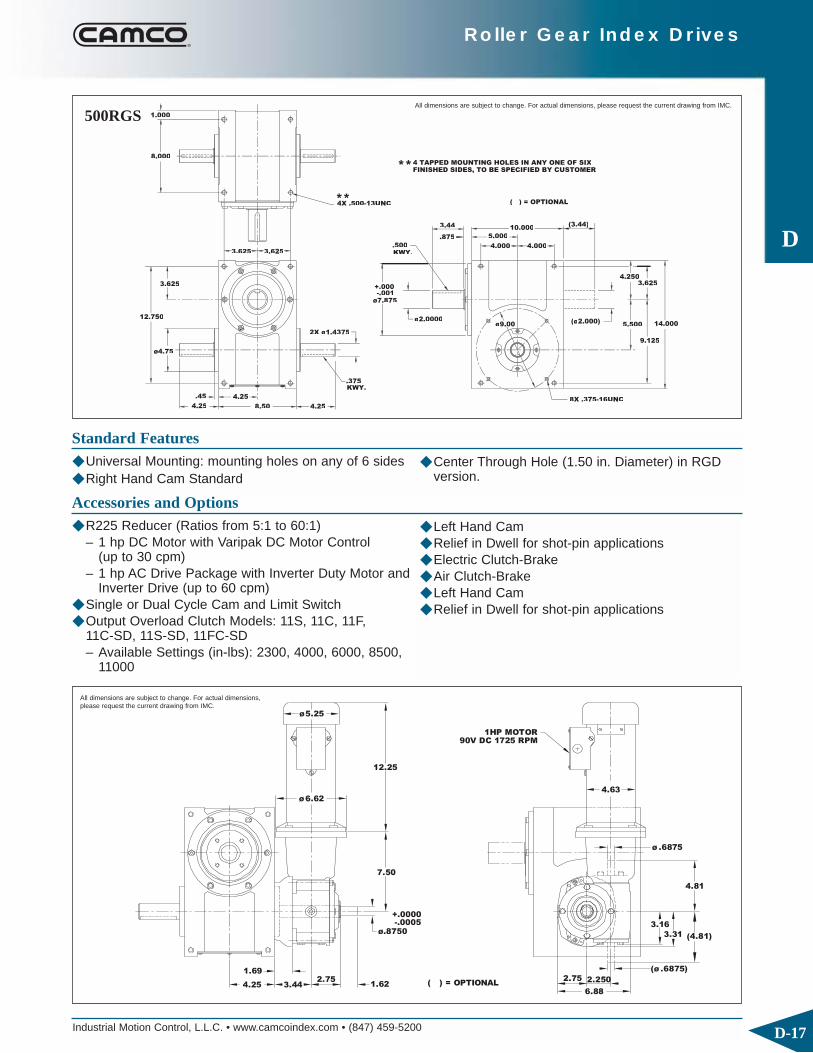
Industrial Motion Control, L.L.C. • www.camcoindex.com • (847) 459-5200 D-17
Roller Gear Index Drives
D
ø4.75
ø
3.625 3.625
1.000
8.000
(3.44)
5.500
4.250
4.254.25 8.50
4.25.45
12.750
3.625
.375KWY.
8X .375-16UNC
2X ø1.4375
ø7.875-.001
+.000
ø2.0000 (ø2.000)
**4 TAPPED MOUNTING HOLES IN ANY ONE OF SIXFINISHED SIDES, TO BE SPECIFIED BY CUSTOMER
KWY..500
.875
**4X .500-13UNC
5.000
4.0004 4.0004
10.000
( ) = OPTIONAL
9.125
14.000
3.625
3.44
Standard Features◆ Universal Mounting: mounting holes on any of 6 sides◆ Right Hand Cam Standard
12.25
7.50
1.69
4.25 3.442.75
1.62
ø6.62
ø5.25
ø .6875
2.75( ) = OPTIONAL
6.88
2.250
(ø .6875)
(4.81)
3.16
3.31
4.81
90V DC 1725 RPM1HP MOTOR
4.63
+.0000-.0005
ø.8750
Accessories and Options◆ R225 Reducer (Ratios from 5:1 to 60:1)
– 1 hp DC Motor with Varipak DC Motor Control(up to 30 cpm)
– 1 hp AC Drive Package with Inverter Duty Motor and Inverter Drive (up to 60 cpm)
◆ Single or Dual Cycle Cam and Limit Switch◆ Output Overload Clutch Models: 11S, 11C, 11F,
11C-SD, 11S-SD, 11FC-SD– Available Settings (in-lbs): 2300, 4000, 6000, 8500,
11000
All dimensions are subject to change. For actual dimensions, please request the current drawing from IMC.
All dimensions are subject to change. For actual dimensions,please request the current drawing from IMC.
◆ Center Through Hole (1.50 in. Diameter) in RGD version.
◆ Left Hand Cam◆ Relief in Dwell for shot-pin applications◆ Electric Clutch-Brake◆ Air Clutch-Brake◆ Left Hand Cam◆ Relief in Dwell for shot-pin applications
500RGS

Industrial Motion Control, L.L.C. • www.camcoindex.com • (847) 459-5200D-18
Roller Gear Index Drives
D
ø9.000
8X .50-13UNC X .75
4X .375-24UNF
.59
3.59
13.75
2X ø
KWY.
16.68
9.50
2X ø1.3749
.312
4.250
8.500
4X .50-13UNC X .88
ø.344 X 75 DEEP
4.250
1.250
+.000 THRU
5.50
11.00
ø
-.0005ø
15.00
12.00
6.250
16.50
4 TAPPED MOUNTING HOLES IN ANY ONE OF SIXFINISHED SIDES, TO BE SPECIFIED BY CUSTOMER
1.38
.28
.50
8.50 1.25
ø2.50
.75
ø6.00
ø3.250ø4.750
**
**
ø8.132
600RGD/600RGSAll dimensions are subject to change. For actual dimensions, please request the current drawing from IMC.
600RGD
600RGD/RGS Indexer CapacitiesStops Index Motion B10 Capacity RGD Internal RGS Internal Model*
(S) Period (β) at 50 RPM (in-lb) Inertia (lb-in2) Inertia (lb-in2)2.0 300 ms 6516 256 137 600RG(D/S)2H48-300
3.0270 ms 7955 256 137 600RG(D/S)3H48-270180 ms 8769 256 137 600RG(D/S)3H48-180
4.0270 ms 6749 249 131 600RG(D/S)4H40-270180 ms 7477 249 131 600RG(D/S)4H40-180270 ms 8286 256 137 600RG(D/S)6H48-270
6.0180 ms 9333 256 137 600RG(D/S)6H48-180120 ms 10286 256 137 600RG(D/S)6H48-12090 ms 10715 256 137 600RG(D/S)6H48-90270 ms 6928 244 126 600RG(D/S)8H40-270
8.0180 ms 7747 244 126 600RG(D/S)8H40-180120 ms 8503 244 126 600RG(D/S)8H40-12090 ms 8936 244 126 600RG(D/S)8H40-90270 ms 4091 244 126 600RG(D/S)12H32-270
12.0180 ms 4610 244 126 600RG(D/S)12H32-180120 ms 5096 244 126 600RG(D/S)12H32-12090 ms 5444 244 126 600RG(D/S)12H32-90270 ms 9553 249 131 600RG(D/S)16H40-270 II
16.0 120 ms 11684 249 131 600RG(D/S)16H40-120 II90 ms 12224 249 131 600RG(D/S)16H40-90 II
Technical SpecificationsOutput Load Capacity – loads carried during index
RGD RGSRadial 5667 lbs 6960 lbsThrust/Axial 3528 lbs 3529 lbsMoment 16292 in-lbs 33548 in-lbs
Accuracy ±40 arcsec / ±.0011" at 6" Radius
Repeatability ±20 arcsec / ±.0006" at 6" Radius
* Specify “D” for Dial (Flange) Output or “S” for Shaft Output.Other Motions (stops and index periods) available. Contact your lMC sales representative for more information.

Industrial Motion Control, L.L.C. • www.camcoindex.com • (847) 459-5200 D-19
Roller Gear Index Drives
DKWY..50
8X .50-13UNC X .75
+.000
.59
13.75
KWY.
16.68
9.50
2X ø1.3749
.312
ø9.000-.001
1.38
4X .50-13UNC X .88
4.250
8.500
1.250
(ø2.250)
11.00
5.50
ø2.250
16.50
15.00
12.00
6.250
4 TAPPED MOUNTING HOLES IN ANY ONE OF SIX
FINISHED SIDES, TO BE SPECIFIED BY CUSTOMER
( ) = OPTIONAL
.50
5.50
1.25
8.50
.75
(4.81)
ø6.00
**
**
ø8.132
Standard Features◆ Universal Mounting: mounting holes on any of 6 sides◆ Right Hand Cam Standard
4.75
3.62
.75
7.691.00
1.5000
180V DC, 1750 RPM1HP MOTOR
7300C GEAR REDUCER
( ) = OPTIONAL
9.56
4.47
12.25
ø6.62
ø5.25
6.58
5.50
4.90
3.00
(ø1.000)
(6.68)
6.68
ø4.62
ø1.000
Accessories and Options◆ 7300C or 7350C Reducer (Ratios from 5:1 to 60:1)◆ 1 or 2 hp DC Motor with Varipak DC Motor Control
(up to 30 cpm)◆ 1 or 2 hp AC Drive Package with Inverter Duty Motor
and Inverter Drive (up to 60 cpm) ◆ Single or Dual Cycle Cam and Limit Switch◆ Output Overload Clutch Models: 11FM, 11SM
– Available Settings (in-lbs): 2300, 4000, 6000, 8500, 11000
All dimensions are subject to change. For actual dimensions, please request the current drawing from IMC.
All dimensions are subject to change. For actual dimensions, please request the current drawing from IMC.
◆ Center Through Hole (1.50 in. Diameter) in RGD version.
◆ Left Hand Cam◆ Relief in Dwell for shot-pin applications◆ Electric Clutch-Brake◆ Air Clutch-Brake◆ Left Hand Cam◆ Relief in Dwell for shot-pin applications
600RGS
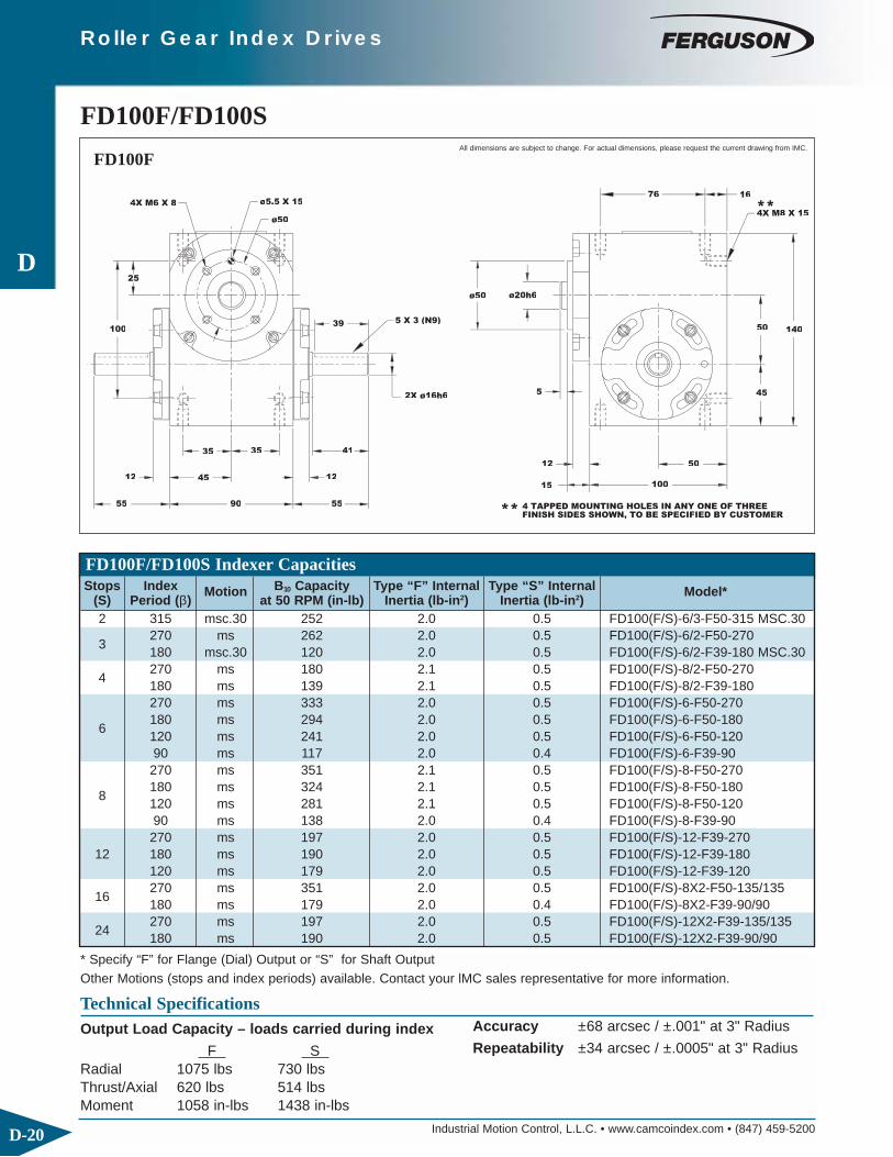
Industrial Motion Control, L.L.C. • www.camcoindex.com • (847) 459-5200D-20
Roller Gear Index Drives
D
ø50
52X ø16h6
5 X 3 (N9)
45
35
55
12
35 41
90 55
12
25
100
4X M6 X 8
39
ø5.5 X 15
4 TAPPED MOUNTING HOLES IN ANY ONE OF THREEFINISH SIDES SHOWN, TO BE SPECIFIED BY CUSTOMER**
15
12
100
50
45
ø20h6
76
14050
4X M8 X 15
16
**
ø50
FD100F/FD100SAll dimensions are subject to change. For actual dimensions, please request the current drawing from IMC.
FD100F
FD100F/FD100S Indexer CapacitiesStops Index Motion B10 Capacity Type “F” Internal Type “S” Internal Model*
(S) Period (β) at 50 RPM (in-lb) Inertia (lb-in2) Inertia (lb-in2)2 315 msc.30 252 2.0 0.5 FD100(F/S)-6/3-F50-315 MSC.30
3270 ms 262 2.0 0.5 FD100(F/S)-6/2-F50-270180 msc.30 120 2.0 0.5 FD100(F/S)-6/2-F39-180 MSC.30
4270 ms 180 2.1 0.5 FD100(F/S)-8/2-F50-270180 ms 139 2.1 0.5 FD100(F/S)-8/2-F39-180270 ms 333 2.0 0.5 FD100(F/S)-6-F50-270
6180 ms 294 2.0 0.5 FD100(F/S)-6-F50-180120 ms 241 2.0 0.5 FD100(F/S)-6-F50-12090 ms 117 2.0 0.4 FD100(F/S)-6-F39-90270 ms 351 2.1 0.5 FD100(F/S)-8-F50-270
8180 ms 324 2.1 0.5 FD100(F/S)-8-F50-180120 ms 281 2.1 0.5 FD100(F/S)-8-F50-12090 ms 138 2.0 0.4 FD100(F/S)-8-F39-90270 ms 197 2.0 0.5 FD100(F/S)-12-F39-270
12 180 ms 190 2.0 0.5 FD100(F/S)-12-F39-180120 ms 179 2.0 0.5 FD100(F/S)-12-F39-120
16270 ms 351 2.0 0.5 FD100(F/S)-8X2-F50-135/135180 ms 179 2.0 0.4 FD100(F/S)-8X2-F39-90/90
24270 ms 197 2.0 0.5 FD100(F/S)-12X2-F39-135/135180 ms 190 2.0 0.5 FD100(F/S)-12X2-F39-90/90
* Specify “F” for Flange (Dial) Output or “S” for Shaft OutputOther Motions (stops and index periods) available. Contact your lMC sales representative for more information.
Technical SpecificationsOutput Load Capacity – loads carried during index
F S Radial 1075 lbs 730 lbsThrust/Axial 620 lbs 514 lbsMoment 1058 in-lbs 1438 in-lbs
Accuracy ±68 arcsec / ±.001" at 3" Radius
Repeatability ±34 arcsec / ±.0005" at 3" Radius

Industrial Motion Control, L.L.C. • www.camcoindex.com • (847) 459-5200 D-21
Roller Gear Index Drives
D5 X 3 (N9)
ø20h6
2X ø16h6
100
35
45
55
12
4135
90 55
12
25
39
4 TAPPED MOUNTING HOLES IN ANY ONE OF THREEFINISH SIDES SHOWN, TO BE SPECIFIED BY CUSTOMER
100
12
65
**
50
45
6 X 3.5 (N9)
50
76
**4X M8 X 15
50 140
16
Standard Features◆ Universal Mounting: mounting holes on any of 3 sides
106 30
ø80
28
40 50
40
45
155
TENV1800RPM, 90 VOLT1/4 HP D.C. MOTOR
GEAR REDUCERBISON 828
ALL DIMENSIONS = MILLIMETERS
Accessories and Options◆ .25 hp DC Gearmotor Drive Package
– Direct Drive or Belt Drive– Varipak DC Motor Control (up to 30 cpm)
◆ Output Overload Clutch Models: RT3 F/S, RT3 F/F, RT3DF– Available Settings (in-lb), Adjustable Ranges:
100-175, 175-275, 250-350, 325-500
All dimensions are subject to change. For actual dimensions, please request the current drawing from IMC.
All dimensions are subject to change. For actual dimensions,please request the current drawing from IMC.
◆ Right Hand Cam
◆ Single or Dual Cycle Cam and Limit Switch◆ Left Hand Cam◆ Relief in Dwell for shot-pin applications
FD100S

Industrial Motion Control, L.L.C. • www.camcoindex.com • (847) 459-5200D-22
Roller Gear Index Drives
D
FINISHED SIDES SHOWN, TO BE SPECIFIED BY CUSTOMER
4 TAPPED MOUNTING HOLES IN ANY ONE OF FOUR**
**
.38 4.88
.19
2.25
.19
2X ø.8750
KWY2.00
.50
5.25
2.62
2.12
4.25
ø.250 X .627.88
4X .38-16UNC X .62ø2.250
4X .38-16UNC X .62
3.250
.25
.38
6.00
3.00
.36
6.25
8.88
+.000
+.000
ø3.000
ø5.250-.001
ø1.500
(ø1.06)
( ) = OPTIONAL
FD162F/FD162SAll dimensions are subject to change. For actual dimensions, please request the current drawing from IMC.
FD162F
* Specify “F” for Flange (Dial) Output or “S” for Shaft OutputOther Motions (stops and index periods) available. Contact your lMC sales representative for more information.
FD162F/FD162S Indexer CapacitiesStops Index Motion B10 Capacity Type “F” Internal Type “S” Internal Model*
(S) Period (β) at 50 RPM (in-lb) Inertia (lb-in2) Inertia (lb-in2)2 300 ms 1053 11 4.2 FD162(F/S)-6/3-F75-300
3270 ms 1340 11 4.2 FD162(F/S)-6/2-F75-270180 ms 1157 11 4.2 FD162(F/S)-6/2-F75-180
4270 ms 1691 11 4.6 FD162(F/S)-8/2-F75-270180 msc.10 1758 11 4.6 FD162(F/S)-8/2-F75-180 MSC.10270 ms 1512 11 4.2 FD162(F/S)-6-F75-270
6 180 ms 1560 11 4.2 FD162(F/S)-6-F75-180120 ms 1526 11 4.2 FD162(F/S)-6-F75-120270 ms 1821 11 4.6 FD162(F/S)-8-F75-270
8 180 ms 1907 11 4.6 FD162(F/S)-8-F75-180120 ms 1939 11 4.6 FD162(F/S)-8-F75-120270 ms 1278 11 4.4 FD162(F/S)-12-F62-270
12 180 ms 1347 11 4.4 FD162(F/S)-12-F62-180120 ms 1396 11 4.4 FD162(F/S)-12-F62-120270 ms 2044 11 4.6 FD162(F/S)-8X2-F75-135/135
16 180 ms 2201 11 4.6 FD162(F/S)-8X2-F75-90/90120 ms 2283 11 4.6 FD162(F/S)-8X2-F75-60/60270 ms 1432 11 4.4 FD162(F/S)-12X2-F62-135/135
24 180 ms 1552 11 4.4 FD162(F/S)-12X2-F62-90/90120 ms 1643 11 4.4 FD162(F/S)-12X2-F62-60/60
Technical SpecificationsOutput Load Capacity – loads carried during index
F S Radial 1465 lbs 2876 lbsThrust/Axial 1112 lbs 1112 lbsMoment 2197 in-lbs 5752 in-lbs
Accuracy ±45 arcsec / ±.0007" at 3" Radius
Repeatability ±22 arcsec / ±.0003" at 3" Radius

Industrial Motion Control, L.L.C. • www.camcoindex.com • (847) 459-5200 D-23
Roller Gear Index Drives
D
FINISHED SIDES SHOWN, TO BE SPECIFIED BY CUSTOMER4 TAPPED MOUNTING HOLES IN ANY ONE OF FOUR**
**.38 4.88
(2.12)
(ø1.250)
KWY
.19
2.25
2X ø.8750
2.00
2.12
5.252
2.62
4.25
.50
7.88
.19
4X .38-16UNC X .62
8.883.250
2.50
.38
6.00
.36
3.00
6.25
ø1.250
ø5.250
KWY.25
( ) = OPTIONAL
Standard Features◆ Universal Mounting: mounting holes on any of 3 sides
6.00 3.30
3.25
7.62
ø4.62
ø6.62
11.13
2.00
2.77 4.15
20CDSF GEAR REDUCER
1800RPM, 90 VOLT
ADAPTOR56C MOTOR
TENV
1/2 HP D.C. MOTOR
Accessories and Options◆ 20CDSF Reducer with 56C Motor Adapter (Ratios of
5:1 to 60:1)◆ 1/2 or 1 hp DC Motor with Varipak DC Motor Control
(up to 30 cpm)◆ 1/3 or 1 hp AC Drive Package with Inverter Duty Motor
and Inverter Drive (up to 60 cpm) ◆ Output Overload Clutch Models: RT5 F/S, RT5 F/F,
RT5DF
All dimensions are subject to change. For actual dimensions, please request the current drawing from IMC.
All dimensions are subject to change. For actual dimensions,please request the current drawing from IMC.
◆ Right Hand Cam
– Available Settings (in-lb), Adjustable Ranges: 500-850, 800-1700, 1600-3000
◆ Single or Dual Cycle Cam and Limit Switch◆ Left Hand Cam◆ Relief in Dwell for shot-pin applications
FD162S

Industrial Motion Control, L.L.C. • www.camcoindex.com • (847) 459-5200D-24
Roller Gear Index Drives
D
.45
1.00
6.00
3.00 3.38 3.38
2.25
2X ø2.250
3.00
( ) = OPTIONAL3.00
9.75
.25
ø6.500
2.25
ø2.250
ø4.00
3.00
6.50
8.00
4.38
4.25 12.00
11.25
4.00
3.00
.45
.25KWY.
**
3X .38-16UNC X .62
4X .38-16UNC X .62
ø.312 X .50
**
4 TAPPED MOUNTING HOLES IN ANY ONE OF SIXFINISHED SIDES SHOWN, TO BE SPECIFIED BY CUSTOMER
FD200F/FD200SAll dimensions are subject to change. For actual dimensions, please request the current drawing from IMC.
FD200F
* Specify “F” for Flange (Dial) Output or “S” for Shaft OutputOther Motions (stops and index periods) available. Contact your lMC sales representative for more information.
FD200F/FD200S Indexer CapacitiesStops Index Motion B10 Capacity Type “F” Internal Type “S” Internal Model*
(S) Period (β) at 50 RPM (in-lb) Inertia (lb-in2) Inertia (lb-in2)2 300 ms 1827 32 14 FD200(F/S)-6/3-F100-300
3270 ms 2248 32 14 FD200(F/S)-6/2-F100-270180 ms 2033 32 14 FD200(F/S)-6/2-F100-180
4270 ms 2710 33 15 FD200(F/S)-8/2-F100-270180 ms 2704 33 15 FD200(F/S)-8/2-F100-180270 ms 2486 32 14 FD200(F/S)-6-F100-270
6 180 ms 2580 32 14 FD200(F/S)-6-F100-180120 ms 2581 32 14 FD200(F/S)-6-F100-120270 ms 2990 33 15 FD200(F/S)-8-F100-270
8 180 ms 3135 33 15 FD200(F/S)-8-F100-180120 ms 3214 33 15 FD200(F/S)-8-F100-120270 ms 2214 31 14 FD200(F/S)-12-F75-270
12 180 ms 2768 31 14 FD200(F/S)-12-F75-180120 ms 2874 31 14 FD200(F/S)-12-F75-120270 ms 3350 33 15 FD200(F/S)-8X2-F100-135/135
16 180 ms 3616 33 15 FD200(F/S)-8X2-F100-90/90120 ms 3784 33 15 FD200(F/S)-8X2-F100-60/60270 ms 2936 31 14 FD200(F/S)-12X2-F75-135/135
24 180 ms 3189 31 14 FD200(F/S)-12X2-F75-90/90120 ms 3382 31 14 FD200(F/S)-12X2-F75-60/60
Technical SpecificationsOutput Load Capacity – loads carried during index
F S Radial 1871 lbs 3615 lbsThrust/Axial 1187 lbs 1246 lbsMoment 3742 in-lbs 9940 in-lbs
Accuracy ±36 arcsec / ±.001" at 6" Radius
Repeatability ±18 arcsec / ±.0005" at 6" Radius

Industrial Motion Control, L.L.C. • www.camcoindex.com • (847) 459-5200 D-25
Roller Gear Index Drives
D
Ø1.500
( ) = OPTIONAL
2.25
3.00
2X Ø2.250
3.00
3.003.38
6.00
3.38
9.75
2.25
Ø6.500
4.25 12.00
3.38
.45
6.50
8.00
3.00
11.25
4.38
4.00 (3.00)
3.00
(Ø1.500)
.45
KWY..25
**
**4X .38-16UNC X .62
KWY.38
FINISHED SIDES SHOWN, TO BE SPECIFIED BY CUSTOMER4 TAPPED MOUNTING HOLES IN ANY ONE OF SIX
Standard Features◆ Universal Mounting: mounting holes on any of 4 sides
7.25
3.95
3.682.63
3.65 5.28
ø6.62
9.06
11.13ø4.62
26CDSF GEAR REDUCER
1800 RPM, 90 VOLT1/2 HP D.C. MOTOR
ADAPTOR56C MOTOR
TENV
Accessories and Options◆ Center Through Hole (1.25 in. Diameter) in F version.◆ 26CDSF Reducer with 56C Motor Adapter (Ratios of
5:1 to 60:1)◆ 1/2 or 1 hp DC Motor with Varipak DC Motor Control
(up to 30 cpm)◆ 1/2 or 1 hp AC Drive Package with Inverter Duty Motor
and Inverter Drive (up to 60 cpm) ◆ Output Overload Clutch Models: RT5 F/S, RT5 F/F,
RT5DF
All dimensions are subject to change. For actual dimensions, please request the current drawing from IMC.
All dimensions are subject to change. For actual dimensions,please request the current drawing from IMC.
◆ Right Hand Cam
– Available Settings (in-lb), Adjustable Ranges: 500-850, 800-1700, 1600-3000
◆ Single or Dual Cycle Cam and Limit Switch◆ Left Hand Cam◆ Relief in Dwell for shot-pin applications
FD200S

Industrial Motion Control, L.L.C. • www.camcoindex.com • (847) 459-5200D-26
Roller Gear Index Drives
D
( ) = OPTIONAL
FINISHED SIDES SHOWN, TO BE SPECIFIED BY CUSTOMER4 TAPPED MOUNTING HOLES IN ANY ONE OF SIX
.31
3.62
2X Ø
2.694.253.62
**
7.25
8.50 3.62
KWY
4X .38-16UNC X .69
2X Ø.312 X .50
**4X .50-13UNC X .88
45°
12.75
3.62
Ø3.250
14.005.50
10.00
.19
.88
8.00
(Ø1.50)
.50
5.005
4.00
9.75
Ø1.9999
Ø8.250-.002
Ø4.50
+.000
+.0000-.0005
FD250F/FD250SAll dimensions are subject to change. For actual dimensions, please request the current drawing from IMC.
FD250F
* Specify “F” for Flange (Dial) Output or “S” for Shaft OutputOther Motions (stops and index periods) available. Contact your lMC sales representative for more information.
FD250F/FD250S Indexer CapacitiesStops Index Motion B10 Capacity Type “F” Internal Type “S” Internal Model*
(S) Period (β) at 50 RPM (in-lb) Inertia (lb-in2) Inertia (lb-in2)2 300 ms 5462 80 67 FD250(F/S)-6/3-F150-300
3270 ms 6984 80 67 FD250(F/S)-6/2-F150-270180 msc.20 6753 80 67 FD250(F/S)-6/2-F150-180 MSC.20
4270 ms 6738 76 63 FD250(F/S)-8/2-F125-270180 ms 6385 76 63 FD250(F/S)-8/2-F125-180270 ms 7872 80 67 FD250(F/S)-6-F150-270
6 180 ms 8117 80 67 FD250(F/S)-6-F150-180120 ms 9483 80 67 FD250(F/S)-6-F150-120270 ms 7275 73 60 FD250(F/S)-8-F125-270
8 180 ms 7606 73 60 FD250(F/S)-8-F125-180120 ms 7730 73 60 FD250(F/S)-8-F125-120270 ms 4952 72 61 FD250(F/S)-12-F100-270
12 180 ms 5221 72 61 FD250(F/S)-12-F100-180120 ms 5410 72 61 FD250(F/S)-12-F100-120270 ms 8150 73 60 FD250(F/S)-8X2-F125-135/135
16 180 ms 8775 73 60 FD250(F/S)-8X2-F125-90/90120 ms 9105 73 60 FD250(F/S)-8X2-F125-60/60270 ms 5545 72 61 FD250(F/S)-12X2-F100-135/135
24 180 ms 6017 72 61 FD250(F/S)-12X2-F100-90/90120 ms 6366 72 61 FD250(F/S)-12X2-F100-60/60
Technical SpecificationsOutput Load Capacity – loads carried during index
F S Radial 3015 lbs 2878 lbsThrust/Axial 2133 lbs 2069 lbsMoment 6784 in-lbs 7656 in-lbs
Accuracy ±26 arcsec / ±.0008" at 6" Radius
Repeatability ±13 arcsec / ±.0004" at 6" Radius

Industrial Motion Control, L.L.C. • www.camcoindex.com • (847) 459-5200 D-27
Roller Gear Index Drives
D
10.00
8.00
2X Ø1.375
4 TAPPED MOUNTING HOLES IN ANY ONE OF SIXFINISHED SIDES SHOWN, TO BE SPECIFIED BY CUSTOMER
2.69
3.62
4.253.62
**
8.50
7.25 ( ) = OPTIONAL
.50
**4X .50-13UNC X .88
3.62
KWY.31
12.75
Ø2.000
Ø8.25
KWY.50 3.81
4.00
5.00
.50
9.75
(Ø2.000)
5.50
3.56
14.00
Standard Features◆ Universal Mounting: mounting holes on any of 6 sides
12.10
9.12
4.02
9.25 3.25
ø6.62
ø 5.25
3.00
4.00 6.00
TEFC
ADAPTOR
56C MOTOR
1800RPM, 90 VOLT
1HP D.C. MOTOR
30CDSF GEAR
REDUCER
Accessories and Options◆ Center Through Hole (1.5 in. Diameter) in F version.◆ 30CDSF Reducer with 56C Motor Adapter (Ratios of
5:1 to 60:1)◆ R3 Reducer with 56C Motor Adapter (Ratios of 5:1
to 60:1)◆ R3 FSC Input Overload Clutch◆ 1 hp DC Motor with Varipak DC Motor Control
(up to 30 cpm)◆ 1 hp AC Drive Package with Inverter Duty Motor
and Inverter Drive (up to 60 cpm)
All dimensions are subject to change. For actual dimensions, please request the current drawing from IMC.
All dimensions are subject to change. For actual dimensions,please request the current drawing from IMC.
◆ Right Hand Cam
◆ Output Overload Clutch Models: RT6 F/S, RT6 F/F,RT6DF– Available Settings (in-lb), Adjustable Ranges:
1000-2700, 2500-5000, 4000-8500◆ R3 FSC Input Overload Clutch◆ Single or Dual Cycle Cam and Limit Switch◆ Left Hand Cam◆ Relief in Dwell for shot-pin applications
FD250S

Industrial Motion Control, L.L.C. • www.camcoindex.com • (847) 459-5200D-28
Roller Gear Index Drives
D Ø3.937
(2.00)
FINISHED SIDES SHOWN, TO BE SPECIFIED BY CUSTOMER
3.62
2.69
2X Ø1.375
**
4.75
9.50
4X .50-13UNC X .88
°
8.50
4.25
3.62
.75
( ) = OPTIONAL
13.75
3.75
4X .50-13UNC X .88
Ø.438 X .75
.312
KWY
**
Ø4.750
Ø9.0000
15.00
5.75
6.25
12.00
1.38
.50
.276
4.25
5.50
8.50
11.00
.50
16.50
.38
FD300F/FD300SAll dimensions are subject to change. For actual dimensions, please request the current drawing from IMC.
FD300F
* Specify “F” for Flange (Dial) Output or “S” for Shaft OutputOther Motions (stops and index periods) available. Contact your lMC sales representative for more information.
FD300F/FD300S Indexer CapacitiesStops Index Motion B10 Capacity Type “F” Internal Type “S” Internal Model*
(S) Period (β) at 50 RPM (in-lb) Inertia (lb-in2) Inertia (lb-in2)2 300 ms 8188 241 118 FD300(F/S)-6/3-F175-300
3270 ms 10215 241 118 FD300(F/S)-6/2-F175-270180 msc.20 10008 241 118 FD300(F/S)-6/2-F175-180 MSC.20
4270 ms 9207 236 113 FD300(F/S)-8/2-F150-270180 ms 8862 236 113 FD300(F/S)-8/2-F150-180270 ms 11352 241 118 FD300(F/S)-6-F175-270
6 180 ms 11764 241 118 FD300(F/S)-6-F175-180120 ms 11655 241 118 FD300(F/S)-6-F175-120270 ms 9859 236 113 FD300(F/S)-8-F150-270
8 180 ms 10327 236 113 FD300(F/S)-8-F150-180120 ms 10539 236 113 FD300(F/S)-8-F150-120270 ms 5139 219 96 FD300(F/S)-12-F100-270
12 180 ms 5422 219 96 FD300(F/S)-12-F100-180120 ms 5627 219 96 FD300(F/S)-12-F100-120270 ms 11044 236 113 FD300(F/S)-8X2-F150-135/135
16 180 ms 11910 236 113 FD300(F/S)-8X2-F150-90/90120 ms 12410 236 113 FD300(F/S)-8X2-F150-60/60270 ms 5753 219 96 FD300(F/S)-12X2-F100-135/135
24 180 ms 6247 219 96 FD300(F/S)-12X2-F100-90/90120 ms 6620 219 96 FD300(F/S)-12X2-F100-60/60
Technical SpecificationsOutput Load Capacity – loads carried during index
F S Radial 2555 lbs 6869 lbsThrust/Axial 1235 lbs 2427 lbsMoment 7347 in-lbs 23562 in-lbs
Accuracy ±40 arcsec / ±.0011" at 6" Radius
Repeatability ±20 arcsec / ±.0006" at 6" Radius

Industrial Motion Control, L.L.C. • www.camcoindex.com • (847) 459-5200 D-29
Roller Gear Index Drives
D
ø 2.2500 (ø 2.250)
**
2.69
3.62
2X ø 1.375
8.50
FINISHED SIDES SHOWN, TO BE SPECIFIED BY CUSTOMER
4 TAPPED MOUNTING HOLES ON ANY ONE OF SIX
11.005.00
4.75
9.50 3.62
1.38
.75
( ) = OPTIONAL
KWY
ø .438 X .75
.312 15.00
13.75
6.25
12.00
.50
4.25
5.50
16.50
4X .50-13UNC X .88 KWY
4X .50-13UNC X .88
45°ø 4.750
4.25
8.50
**
.250
3.75
ø 9.000
(5.00)
.50.38
Standard Features◆ Universal Mounting: mounting holes on any of 6 sides
1800 RPM, 90 VOLT
56C MOTOR
ADAPTOR
1HP D.C. MOTOR
TEFC
6SFM GEAR REDUCER
4.50
9.25 4.56
ø6.62
ø5.25
4.19
10.13
12.10
6.50
3.50
Accessories and Options◆ Center Through Hole (2.0 in. Diameter) in F version.◆ 6SFM Reducer with 56C Motor Adapter (Ratios of 5:1
to 60:1)◆ R3 Reducer with 56C Motor Adapter (Ratios of 5:1
to 60:1)◆ R3 FSC Input Overload Clutch◆ 1 or 2 hp DC Motor with Varipak DC Motor Control
(up to 30 cpm)◆ 1 or 2 hp AC Drive Package with Inverter Duty Motor
and Inverter Drive (up to 60 cpm)
All dimensions are subject to change. For actual dimensions, please request the current drawing from IMC.
All dimensions are subject to change. For actual dimensions,please request the current drawing from IMC.
◆ Right Hand Cam
◆ Output Overload Clutch Models: DTL-10– Available Settings (in-lb), Adjustable Range:
1800-4400◆ R3 FSC Input Overload Clutch◆ Single or Dual Cycle Cam and Limit Switch◆ Left Hand Cam◆ Relief in Dwell for shot-pin applications
FD300S
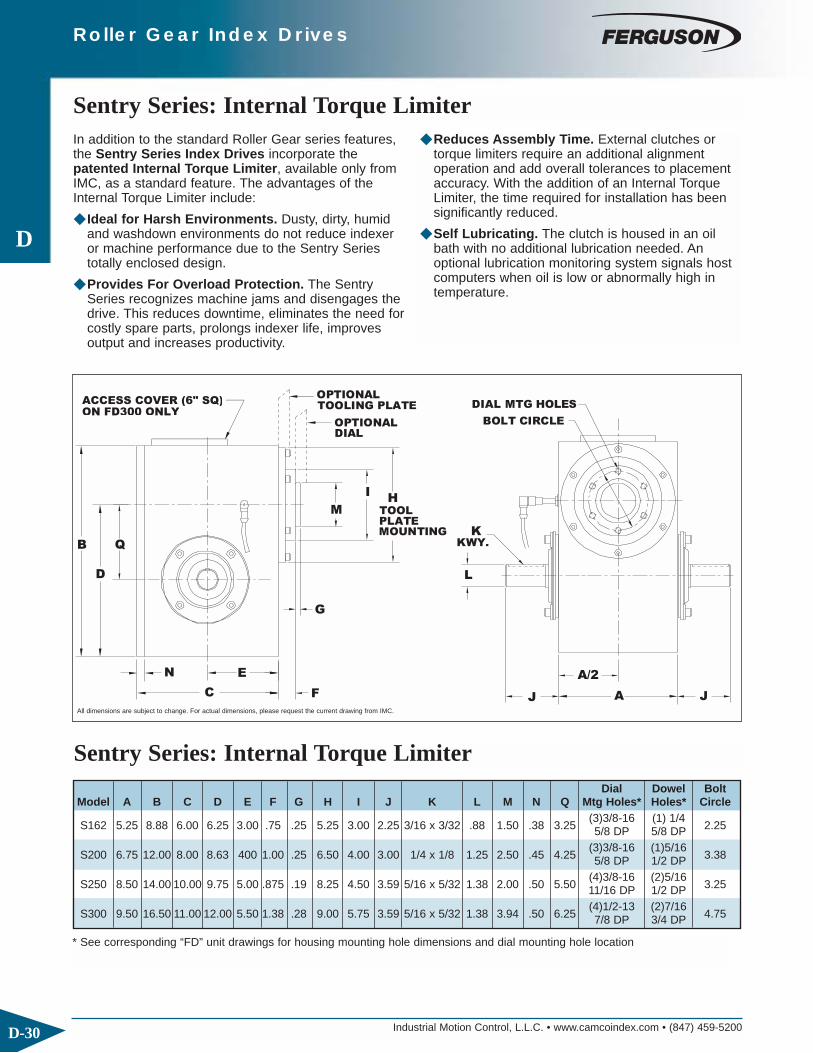
Industrial Motion Control, L.L.C. • www.camcoindex.com • (847) 459-5200D-30
Roller Gear Index Drives
D
Sentry Series: Internal Torque LimiterIn addition to the standard Roller Gear series features, the Sentry Series Index Drives incorporate thepatented Internal Torque Limiter, available only fromIMC, as a standard feature. The advantages of theInternal Torque Limiter include:
◆ Ideal for Harsh Environments. Dusty, dirty, humidand washdown environments do not reduce indexeror machine performance due to the Sentry Series totally enclosed design.
◆ Provides For Overload Protection. The SentrySeries recognizes machine jams and disengages the drive. This reduces downtime, eliminates the need for costly spare parts, prolongs indexer life, improves output and increases productivity.
◆ Reduces Assembly Time. External clutches or torque limiters require an additional alignmentoperation and add overall tolerances to placement accuracy. With the addition of an Internal Torque Limiter, the time required for installation has been significantly reduced.
◆ Self Lubricating. The clutch is housed in an oil bath with no additional lubrication needed. An optional lubrication monitoring system signals hostcomputers when oil is low or abnormally high in temperature.
MOUNTING
QB
N
D
E
C F
G
OPTIONALDIAL
I
MPLATETOOL
H
OPTIONALTOOLING PLATE
KWY.
A/2
J A
L
J
K
DIAL MTG HOLES
BOLT CIRCLE
ACCESS COVER (6" SQ)ON FD300 ONLY
Sentry Series: Internal Torque Limiter
All dimensions are subject to change. For actual dimensions, please request the current drawing from IMC.
* See corresponding “FD” unit drawings for housing mounting hole dimensions and dial mounting hole location
Dial Dowel BoltModel A B C D E F G H I J K L M N Q Mtg Holes* Holes* Circle
(3)3/8-16 (1) 1/4S162 5.25 8.88 6.00 6.25 3.00 .75 .25 5.25 3.00 2.25 3/16 x 3/32 .88 1.50 .38 3.25 5/8 DP 5/8 DP 2.25
(3)3/8-16 (1)5/16S200 6.75 12.00 8.00 8.63 400 1.00 .25 6.50 4.00 3.00 1/4 x 1/8 1.25 2.50 .45 4.25 5/8 DP 1/2 DP 3.38
(4)3/8-16 (2)5/16S250 8.50 14.00 10.00 9.75 5.00 .875 .19 8.25 4.50 3.59 5/16 x 5/32 1.38 2.00 .50 5.50 11/16 DP 1/2 DP 3.25
(4)1/2-13 (2)7/16S300 9.50 16.50 11.00 12.00 5.50 1.38 .28 9.00 5.75 3.59 5/16 x 5/32 1.38 3.94 .50 6.25 7/8 DP 3/4 DP 4.75

Industrial Motion Control, L.L.C. • www.camcoindex.com • (847) 459-5200 D-31
Roller Gear Index Drives
D
Reducer Mounting Position
A-2-LH B-2-LH
RH B-1-RH
A-2-RHB-2-RH C-2-LH
A-1-LH C-1-RH
C-2-RHD-2-RH D-2-LH
C-1-LH D-1-RH
1. Model
2. Ratio◆ 5:1, 10:1, 15:1, 20:1, 25:1, 30:1, 40:1, 50:1, 60:1
3. Motor Adapter
4. Reducer Input Shaft Extension◆ Single Input (SE) or Double Input (DE)
5. Mounting◆ Mounting Position A, B, C, or D◆ Mounted on Indexer Side 1 or Side 2
6. Input Shaft Orientation◆ Left or Right (See Diagram Below)
1. Model
2. Input Shaft Configuration◆ Side 1◆ Side 2◆ Double Input – DI (Standard)
Indexer Ordering Procedure3. Cam Lead (Helix)
◆ Right Hand (Standard)◆ Left Hand
NOTE: Input may rotate in either direction to achievedesired direction of output rotation.
4. Indexer Mounting Position: 1-6
Indexer Mounting Position
AE: Input Shaft
(Standard)
Cam Lead
Right Hand
2
Position of Shafts
Left Hand
Double Input (DI)p ( ) 1
5AS
3
Input
1
AS: Output Shaft
AE AE
AS
AE
AE
6
AS
4
AS
AS
AE
ASAE
2
Reducer Ordering Procedure

Industrial Motion Control, L.L.C. • www.camcoindex.com • (847) 459-5200D-32
Roller Gear Index Drives
D

CAMCO Parallel Index Drives Center Distance (Dimension “A”)
Supplement to Catalog Section E
Industrial Motion Control, LLC | 1444 S Wolf Rd | Wheeling, IL 60090 USA T: 847-459-5200 | F: 847-459-3064
[email protected] | www.camcoindex.com 10-6-2005
250P 387P 512P
Model Center
Distance "A"
Model Center
Distance "A"
Model Center
Distance "A"
250P1H20-300 3.250 387P1H28-300 4.812 512P1H48-330 5.979 250P1.5H20-270 3.250 387P1.33H28-315 4.812 512P1.33H48-330 5.979 250P2H20-270 3.250 387P1.5H28-300 4.812 512P1.5H48-330 5.979 250P2H20-180 3.250 387P2H32-270 4.812 512P2H40-270 5.979 250P3H20-270 2.750 387P2H32-180 4.812 512P2H40-180 5.979 250P3H20-180 2.750 387P2.67H28-270 II 4.812 512P2H40-120 5.979 250P3H20-120 3.250 387P3H28-270 4.000 512P2.67H40-300 II 5.979 250P4H20-270 2.750 387P3H28-180 4.812 512P3H40-270 4.858 250P4H20-180 2.750 387P3H28-120 4.812 512P3H40-180 5.979 250P4H20-120 3.250 387P4H28-270 4.000 512P4H40-270 4.858 250P4H20-90 3.250 387P4H28-180 4.000 512P4H40-180 4.858 250P6H20-270 II 2.750 387P4H28-120 4.812 512P4H40-120 5.979 250P6H24-180 II 2.750 387P4H28-90 4.812 512P6H40-270 II 4.858 250P8H20-270 II 2.750 387P6H28-270 II 4.000 512P6H40-180 II 5.979 250P8H20-180 II 2.750 387P6H28-180 II 4.812 512P8H40-270 II 4.858 250P8H20-120 II 3.250 387P8H28-270 II 4.000 512P8H40-180 II 5.979 250P12H20-270 II 2.750 387P8H28-180 II 4.000 512P10H40-180 II 5.979 250P12H20-180 II 2.750 387P8H28-120 II 4.812 387P12H28-180 II 4.000 387P12H32-120 II 4.812
662P 900P 1200P
Model Center
Distance "A"
Model Center
Distance "A"
Model Center
Distance "A"
662P1H48-330 7.729 900P1H72-330 10.500 1200P1H112-330 14.000 662P1.33H64-330 7.729 900P1.33H96-300 10.500 1200P1.33H112-330 14.000 662P1.5H64-270 7.729 900P1.5H72-330 10.500 1200P1.5H112-330 14.000 662P2H48-270 7.729 900P2H72-270 10.500 1200P2H96-270 14.000 662P2H56-180 7.729 900P2H72-180 10.500 1200P2H96-180 14.000 662P3H48-270 6.628 900P3H72-270 8.531 1200P3H96-270 14.000 662P3H48-180 7.729 900P3H72-180 10.500 1200P3H96-180 14.000 662P4H48-270 6.628 900P4H72-270 8.531 1200P4H96-270 11.375 662P4H48-180 6.628 900P4H72-180 8.531 1200P4H96-180 11.375 662P4H48-120 7.729 900P4H72-120 10.500 1200P4H96-120 14.000 662P6H48-270 II 6.628 900P6H72-270 II 8.531 1200P4H96-90 14.000 662P6H48-180 II 7.729 900P6H72-180 II 10.500 1200P6H96-270 II 11.375 662P8H48-270 II 6.628 900P8H72-270 II 8.531 1200P6H96-180 II 14.000 662P8H48-180 II 7.729 900P8H72-180 II 10.500 1200P8H96-270 II 11.375 662P8H48-120 7.729 1200P8H96-180 II 14.000 662P12H48-180 II 6.628 1200P8H96-120 II 14.000

FeaturesIMC Parallel Index Drives are ideal for high-speed applications or for actuation-type applications such as driving a linkage or a conveyor. Parallel Index Drivefeatures include:
◆ Hardened and ground conjugate cams
◆ Yoke-mounted, preloaded cam followers are non-reversing for high capacity and speed capability
◆ Whole or fractions stops, oscillating and complex custom motions are available
◆ Long Transfer Distances achieved with simple linkages.
◆ Preloaded, tapered roller bearings for rigidity and backlash-free operation.
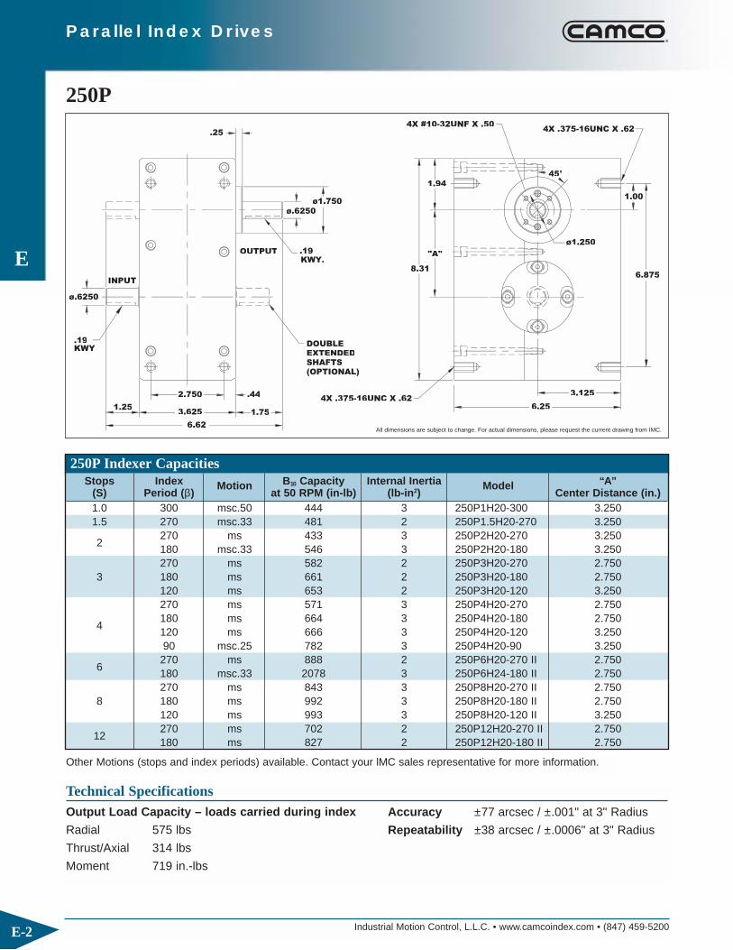
Industrial Motion Control, L.L.C. • www.camcoindex.com • (847) 459-5200
E
E-2
Parallel Index Drives
250P
4X .375-16UNC X .621.25
KWY.19
ø.6250
INPUT
1.75
6.62
2.750
3.625
.44
DOUBLEEXTENDEDSHAFTS(OPTIONAL)
OUTPUTKWY..19
ø1.750
ø.6250
.25
8.316.875
6.25
3.125
4X .375-16UNC X .62
45°
"A"
1.94
4X #10-32UNF X .50
1.00
ø1.250
Technical SpecificationsOutput Load Capacity – loads carried during index
Radial 575 lbs
Thrust/Axial 314 lbs
Moment 719 in.-lbs
All dimensions are subject to change. For actual dimensions, please request the current drawing from IMC.
Accuracy ±77 arcsec / ±.001" at 3" Radius
Repeatability ±38 arcsec / ±.0006" at 3" Radius
250P Indexer Capacities
Other Motions (stops and index periods) available. Contact your lMC sales representative for more information.
Stops Index Motion B10 Capacity Internal Inertia Model “A”(S) Period (β) at 50 RPM (in-lb) (lb-in2) Center Distance (in.)1.0 300 msc.50 444 3 250P1H20-300 3.2501.5 270 msc.33 481 2 250P1.5H20-270 3.250
2270 ms 433 3 250P2H20-270 3.250180 msc.33 546 3 250P2H20-180 3.250270 ms 582 2 250P3H20-270 2.750
3 180 ms 661 2 250P3H20-180 2.750120 ms 653 2 250P3H20-120 3.250270 ms 571 3 250P4H20-270 2.750
4180 ms 664 3 250P4H20-180 2.750120 ms 666 3 250P4H20-120 3.25090 msc.25 782 3 250P4H20-90 3.250
6270 ms 888 2 250P6H20-270 II 2.750180 msc.33 2078 3 250P6H24-180 II 2.750270 ms 843 3 250P8H20-270 II 2.750
8 180 ms 992 3 250P8H20-180 II 2.750120 ms 993 3 250P8H20-120 II 3.250
12270 ms 702 2 250P12H20-270 II 2.750180 ms 827 2 250P12H20-180 II 2.750
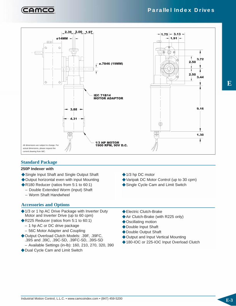
Industrial Motion Control, L.L.C. • www.camcoindex.com • (847) 459-5200
E
E-3
Parallel Index Drives
1/3 HP MOTOR1900 RPM, 90V D.C.
MOTOR ADAPTORIEC 71B14
ø.7846 (19MM)
3.88
4.31
ø14MM
1.972.39
1.30
9.16
1.75
2.50
2.503.44
3.13
1.91
3.72
◆ Single Input Shaft and Single Output Shaft◆ Output horizontal even with input Mounting◆ R180 Reducer (ratios from 5:1 to 60:1)
– Double Extended Worm (input) Shaft– Worm Shaft Handwheel
Standard Package250P Indexer with
◆ 1/3 hp DC motor◆ Varipak DC Motor Control (up to 30 cpm)◆ Single Cycle Cam and Limit Switch
◆ 1/3 or 1 hp AC Drive Package with Inverter Duty Motor and Inverter Drive (up to 60 cpm)
◆ R225 Reducer (ratios from 5:1 to 60:1)– 1 hp AC or DC drive package– 56C Motor Adapter and Coupling
◆ Output Overload Clutch Models: .39F, .39FC,.39S and .39C, .39C-SD, .39FC-SD, .39S-SD– Available Settings (in-lb): 160, 210, 270, 320, 390
◆ Dual Cycle Cam and Limit Switch
All dimensions are subject to change. For
actual dimensions, please request the
current drawing from IMC.
Accessories and Options
◆ Electric Clutch-Brake◆ Air Clutch-Brake (with R225 only)◆ Oscillating motion◆ Double Input Shaft◆ Double Output Shaft◆ Output and Input Vertical Mounting◆ 180-IOC or 225-IOC Input Overload Clutch

Industrial Motion Control, L.L.C. • www.camcoindex.com • (847) 459-5200
E
E-4
Parallel Index Drives
387P
4X .312-24UNF X .75
12.00
KWY
KWY
INPUT.25
5.38
4.25 .564X .50-13NC X .88
OUTPUT
ø1.000 ø2.500
.25
1.81
8.750
4.38
9.75
'A'
2.81
45°
4.375
1.56
4X .50-13NC X .88
DOUBLEEXTENDEDSHAFTS(OPTIONAL)
1.81
ø1.000
ø2.000
Technical SpecificationsOutput Load Capacity – loads carried during index
Radial 1,627 lbs
Thrust/Axial 577 lbs
Moment 2,945 in.-lbs
All dimensions are subject to change. For actual dimensions, please request the current drawing from IMC.
Accuracy ±50 arcsec / ±.0007" at 3" Radius
Repeatability ±25 arcsec / ±.0004" at 3" Radius
387P Indexer Capacities
Other Motions (stops and index periods) available. Contact your lMC sales representative for more information.
Stops Index Motion B10 Capacity Internal Inertia Model “A”(S) Period (β) at 50 RPM (in-lb) (lb-in2) Center Distance (in.)1 300 msc.66 1385 14 387P1H28-300 4.812
1.33 315 msc.10 1062 13 387P1.33H28-315 4.8121.5 300 ms 1099 13 387P1.5H28-300 4.812
2270 msc.33 1788 14 387P2H32-270 4.812180 msc.33 2095 14 387P2H32-180 4.812
2.67 270 msc.33 2171 14 387P2.67H28-270 II 4.812270 ms 1601 13 387P3H28-270 4.000
3 180 ms 1625 13 387P3H28-180 4.812120 msc.33 2067 14 387P3H28-120 4.812270 ms 1605 14 387P4H28-270 4.000
4180 ms 1865 14 387P4H28-180 4.000120 ms 1835 14 387P4H28-120 4.81290 msc.33 2214 14 387P4H28-90 4.812
6270 ms 2445 13 387P6H28-270 II 4.000180 ms 2463 13 387P6H28-180 II 4.812270 ms 2378 14 387P8H28-270 II 4.000
8 180 ms 2789 14 387P8H28-180 II 4.000120 ms 2730 14 387P8H28-120 II 4.812
12180 ms 2378 14 387P12H28-180 II 4.000120 ms 4220 14 387P12H32-120 II 4.812
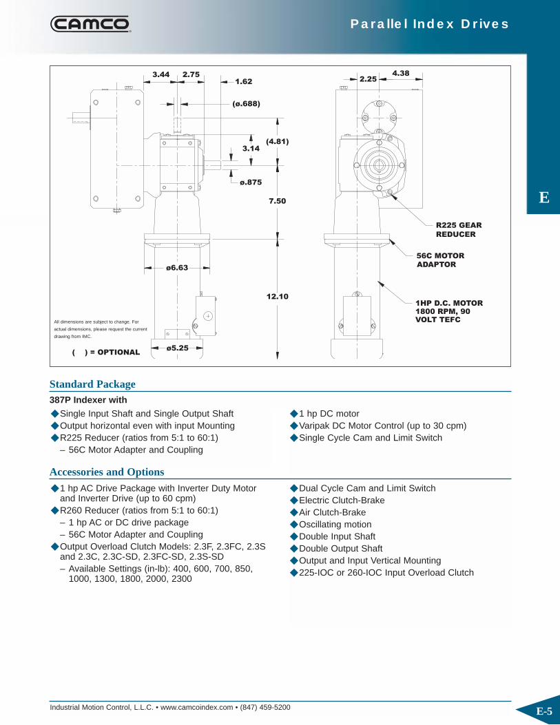
E
Parallel Index Drives
( ) = OPTIONAL
REDUCER
R225 GEAR
1HP D.C. MOTOR 1800 RPM, 90 VOLT TEFC
ADAPTOR56C MOTOR
12.10
ø.875
7.50
3.44 2.75
3.14(4.81)
1.62 2.254.38
(ø.688)
ø6.63
ø5.25
Industrial Motion Control, L.L.C. • www.camcoindex.com • (847) 459-5200 E-5
◆ Single Input Shaft and Single Output Shaft◆ Output horizontal even with input Mounting◆ R225 Reducer (ratios from 5:1 to 60:1)
– 56C Motor Adapter and Coupling
Standard Package387P Indexer with
◆ 1 hp DC motor◆ Varipak DC Motor Control (up to 30 cpm)◆ Single Cycle Cam and Limit Switch
Accessories and Options
All dimensions are subject to change. For
actual dimensions, please request the current
drawing from IMC.
◆ 1 hp AC Drive Package with Inverter Duty Motor and Inverter Drive (up to 60 cpm)
◆ R260 Reducer (ratios from 5:1 to 60:1)– 1 hp AC or DC drive package– 56C Motor Adapter and Coupling
◆ Output Overload Clutch Models: 2.3F, 2.3FC, 2.3Sand 2.3C, 2.3C-SD, 2.3FC-SD, 2.3S-SD– Available Settings (in-lb): 400, 600, 700, 850,
1000, 1300, 1800, 2000, 2300
◆ Dual Cycle Cam and Limit Switch◆ Electric Clutch-Brake◆ Air Clutch-Brake◆ Oscillating motion◆ Double Input Shaft◆ Double Output Shaft◆ Output and Input Vertical Mounting◆ 225-IOC or 260-IOC Input Overload Clutch

Industrial Motion Control, L.L.C. • www.camcoindex.com • (847) 459-5200
E
E-6
Parallel Index Drives
512P
16.00
2.56
ø1.4375
6.25
7.50
.62
(ø1.375)
.06
ø1.6250 ø3.25
2.56
"A"
11.50
5.75
14.75
4.12
45°
5.750
3.50
4X .50-13UNC
4X .375-24UNF X .75
.38.31KWY
.38KWY
INPUT
DOUBLE
EXTENDED
SHAFTS
(OPTIONAL)
KWY
OUTPUT
4X .50-13UNC
ø2.375
Technical SpecificationsOutput Load Capacity – loads carried during index
Radial 4,937 lbs
Thrust/Axial 1,374 lbs
Moment 12,638 in.-lbs
All dimensions are subject to change. For actual dimensions, please request the current drawing from IMC.
Accuracy ±39 arcsec / ±.0006" at 3" Radius
Repeatability ±19 arcsec / ±.0003" at 3" Radius
512P Indexer Capacities
Other Motions (stops and index periods) available. Contact your lMC sales representative for more information.
Stops Index Motion B10 Capacity Internal Inertia Model “A”(S) Period (β) at 50 RPM (in-lb) (lb-in2) Center Distance (in.)1 330 msc.75 6441 63 512P1H48-330 5.979
1.33 330 msc.33 4928 61 512P1.33H48-330 5.9791.5 330 ms 4860 63 512P1.5H48-330 5.979
270 msc.33 4373 61 512P2H40-270 5.9792 180 msc.50 5416 61 512P2H40-180 5.979
120 msc.50 4131 61 512P2H40-120 5.979300 msc.33 7116 61 512P2.67H40-300 II 5.979
3 270 ms 5425 56 512P3H40-270 4.858180 ms 5462 56 512P3H40-180 5.979270 ms 5619 61 512P4H40-270 4.858
4 180 ms 6494 61 512P4H40-180 4.858120 ms 6252 61 512P4H40-120 5.979
6270 ms 8315 56 512P6H40-270 II 4.858180 ms 8261 56 512P6H40-180 II 5.979
8270 ms 8387 61 512P8H40-270 II 4.858180 ms 7894 61 512P8H40-180 II 5.979
10 180 ms 7165 61 512P10H40-180 II 5.979

Industrial Motion Control, L.L.C. • www.camcoindex.com • (847) 459-5200
E
E-7
Parallel Index Drives
2.753.44
12.10
ø.875
1.62
(4.81)
3.14
7.50
5.752.25
(ø.688)
ø6.63
ø5.25
REDUCER
R225 GEAR
( ) = OPTIONAL
56C MOTOR
ADAPTOR
1 HP D.C. MOTOR1800 RPM, 90VOLT TEFC
◆ Single Input Shaft and Single Output Shaft◆ Output horizontal even with input Mounting◆ R225 Reducer (ratios from 5:1 to 60:1)
– 56C Motor Adapter and Coupling
Standard Package512P Indexer with
◆ 1 hp DC motor◆ Varipak DC Motor Control (up to 30 cpm)◆ Single Cycle Cam and Limit Switch
Accessories and Options
All dimensions are subject to change. For
actual dimensions, please request the current
drawing from IMC.
◆ 1 hp AC Drive Package with Inverter Duty Motor and Inverter Drive (up to 60 cpm)
◆ R260 Reducer (ratios from 5:1 to 60:1)– 1 hp AC or DC drive package– 56C Motor Adapter and Coupling
◆ Output Overload Clutch Models: 6.0F, 6.0FC, 6.0Sand 6.0C, 6.0C-SD, 6.0FC-SD, 6.0S-SD– Available Settings (in-lb): 670, 825, 1100, 1400,
1700, 2000, 2300, 2500, 3000, 3800, 4000,5000, 6000
◆ Dual Cycle Cam and Limit Switch◆ Electric Clutch-Brake◆ Air Clutch-Brake◆ Oscillating motion◆ Double Input Shaft◆ Double Output Shaft◆ Output and Input Vertical Mounting◆ 225-IOC or 260-IOC Input Overload Clutch

Industrial Motion Control, L.L.C. • www.camcoindex.com • (847) 459-5200
E
E-8
Parallel Index Drives
662P4X .375-24UNF X .75
ø2.000ø1.500
KWY
ø
KWY.38
DOUBLE EXTENDEDSHAFTS(OPTIONAL)
4X .625-11UNC
KWY
4X .625-11UNC
7.25
.50
3.29
.75
.50 "A"
ø4.250
15.38
.06
8.75 3.31
5.00
7.25
ø3.250
20.12
18.625
45°
14.500
7.250
4.250
All dimensions are subject to change. For actual dimensions, please request the current drawing from IMC.
Technical SpecificationsOutput Load Capacity – loads carried during index
Radial 7,118 lbs
Thrust/Axial 2,042 lbs
Moment 23,562 in.-lbs
Accuracy ±35 arcsec / ±.001" at 6" Radius
Repeatability ±18 arcsec / ±.0005" at 6" Radius
662P Indexer Capacities
Other Motions (stops and index periods) available. Contact your lMC sales representative for more information.
Stops Index Motion B10 Capacity Internal Inertia Model “A”(S) Period (β) at 50 RPM (in-lb) (lb-in2) Center Distance (in.)1 330 msc.50 5824 138 662P1H48-330 7.729
1.33 330 msc.20 10368 332 662P1.33H64-330 7.7291.5 270 msc.33 12617 306 662P1.5H64-270 7.729
2270 msc.33 6811 181 662P2H48-270 7.729180 msc.50 11760 204 662P2H56-180 7.729
3270 ms 8446 166 662P3H48-270 6.628180 ms 8506 166 662P3H48-180 7.729270 ms 8752 181 662P4H48-270 6.628
4 180 ms 10118 181 662P4H48-180 6.628120 ms 9738 181 662P4H48-120 7.729
6270 ms 12946 166 662P6H48-270 II 6.628180 ms 12863 166 662P6H48-180 II 7.729270 ms 13060 181 662P8H48-270 II 6.628
8 180 ms 12293 181 662P8H48-180 II 7.729120 msc.33 15780 181 662P8H48-120 7.729
12 180 ms 13552 662P12H48-180 II 6.628

Industrial Motion Control, L.L.C. • www.camcoindex.com • (847) 459-5200
E
E-9
Parallel Index Drives
( ) = OPTIONAL
145TC MOTORADAPTOR
REDUCER7300C GEAR
1800RPM,
180 VOLT TEFC
2HP D.C. MOTOR
(6.69)
16.30
ø6.62
(ø1.000)
4.62
ø1.938
3.62 4.06 4.50
9.56
3.41 7.253.00
4.90
◆ Single Input Shaft and Single Output Shaft◆ Output horizontal even with input Mounting◆ 7300C Reducer (ratios from 5:1 to 60:1)
– Motor Adapter and Coupling
Standard Package662P Indexer with
◆ 2 hp DC motor◆ Varipak DC Motor Control (up to 30 cpm)◆ Single Cycle Cam and Limit Switch
Accessories and Options
All dimensions are subject to
change. For actual dimensions,
please request the current
drawing from IMC.
◆ 1 or 2 hp AC Drive Package with Inverter Duty Motor and Inverter Drive (up to 60 cpm)
◆ 7350C or 7400C Reducer (ratios from 5:1 to 60:1) with Motor Adapter and Coupling
◆ 1 hp DC Motor ◆ Output Overload Clutch Models: 11F, 11FC,
11FC-SD– Available Settings (in-lb): 2300, 4000, 6000,
8500, 11000
◆ Dual Cycle Cam and Limit Switch◆ Electric Clutch-Brake◆ Air Clutch-Brake◆ Oscillating motion◆ Double Input Shaft◆ Double Output Shaft◆ Output and Input Vertical Mounting◆ 300-IOC or 350-IOC Input Overload Clutch

Industrial Motion Control, L.L.C. • www.camcoindex.com • (847) 459-5200
E
E-10
Parallel Index Drives
900P
1.0010.503.81
ø2.188
8.75
ø2.000
.88
10.500
.75
ø
ø5.000
ø9.94
3.81
6.50
19.50
ø4.250
9.750
5.62
25.00
26.75
OUTPUT
INPUT
4X .625-11UNC
.50KWY
.50KWY
DOUBLEEXTENDEDSHAFTS(OPTIONAL)
4X .50-20UNF X 1.00
Technical SpecificationsOutput Load Capacity – loads carried during index
Radial 7,752 lbs
Thrust/Axial 4,036 lbs
Moment 21,318 in.-lbs
All dimensions are subject to change. For actual dimensions, please request the current drawing from IMC.
Accuracy ±27 arcsec / ±.0008" at 6" Radius
Repeatability ±13 arcsec / ±.0004" at 6" Radius
900P Indexer Capacities
Other Motions (stops and index periods) available. Contact your lMC sales representative for more information.
Stops Index Motion B10 Capacity Internal Inertia Model “A”(S) Period (β) at 50 RPM (in-lb) (lb-in2) Center Distance (in.)1 330 msc.50 20204 760 900P1H72-330 10.500
1.33 300 msc.33 32444 1375 900P1.33H96-300 10.5001.5 330 ms 19950 677 900P1.5H72-330 10.500
2270 msc.33 23507 760 900P2H72-270 10.500180 msc.50 29121 760 900P2H72-180 10.500
3270 ms 29210 676 900P3H72-270 8.531180 ms 29383 676 900P3H72-180 10.500270 ms 30195 760 900P4H72-270 8.531
4 180 ms 34917 760 900P4H72-180 8.531120 ms 33614 760 900P4H72-120 10.500
6270 ms 44661 676 900P6H72-270 II 8.531180 ms 44381 676 900P6H72-180 II 10.500
8270 ms 45053 760 900P8H72-270 II 8.531180 ms 42408 760 900P8H72-180 II 10.500

Industrial Motion Control, L.L.C. • www.camcoindex.com • (847) 459-5200
E
E-11
Parallel Index Drives
ADAPTOR
( ) = OPTIONAL
184TC MOTOR
REDUCER7500C GEAR
5HP A.C. MOTOR1725 RPM, TEFC208-230-460 VOLTNEMA 184TC FRAME
13.80
13.69
7.00
ø2.750
(10.50)
6.75
(ø1.50)
6.25 1.00
5.62 5.00
7.32
9.75
ø7.72
◆ Single Input Shaft and Single Output Flange◆ Output horizontal even with input Mounting◆ 7500C Reducer (ratios from 5:1 to 60:1)
– Motor Adapter and Coupling
Standard Package900P Indexer with
◆ 5 hp AC motor with AC Inverter Drive◆ Single Cycle Cam and Limit Switch
Accessories and Options
All dimensions are subject to change. For
actual dimensions, please request the current
drawing from IMC.
◆ 7600C Reducer (ratios from 5:1 to 60:1) with MotorAdapter and Coupling
◆ Output Overload Clutch Models: 25F, 25FC,25FC-SD– Available Settings (in-lbs): 5000, 7000, 10000,
13000, 15000, 20000, 25000 ◆ Dual Cycle Cam and Limit Switch◆ Electric Clutch-Brake
◆ Air Clutch-Brake◆ 500-IOC or 600-IOC Input Overload Clutch◆ Oscillating motion◆ Double Input Shaft◆ Double Output Shaft◆ Output and Input Vertical Mounting
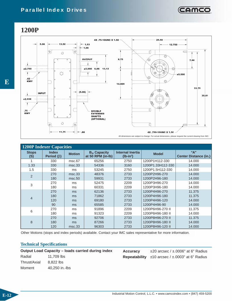
Industrial Motion Control, L.L.C. • www.camcoindex.com • (847) 459-5200
E
E-12
Parallel Index Drives
1200P
ø2.938
.8811.75
(5.06)
ø2.750
5.06
ø3.000 13.126.88
1.06
1.5313.50
14.000
35.81
33.75
12.750
8.75
25.50
ø5.500
7.88
4X .75-10UNC X 1.50
.75
KWY
INPUT
SHAFTS
(OPTIONAL)
DOUBLEEXTENDED
.62
KWY
OUTPUT
4X .750-10UNC X 1.50
Technical SpecificationsOutput Load Capacity – loads carried during index
Radial 11,709 lbs
Thrust/Axial 8,822 lbs
Moment 40,250 in.-lbs
All dimensions are subject to change. For actual dimensions, please request the current drawing from IMC.
Accuracy ±20 arcsec / ±.0006" at 6" Radius
Repeatability ±10 arcsec / ±.0003" at 6" Radius
1200P Indexer Capacities
Other Motions (stops and index periods) available. Contact your lMC sales representative for more information.
Stops Index Motion B10 Capacity Internal Inertia Model “A”(S) Period (β) at 50 RPM (in-lb) (lb-in2) Center Distance (in.)1 330 msc.67 65256 2750 1200P1H112-330 14.000
1.33 330 msc.33 54336 3160 1200P1.33H112-330 14.0001.5 330 ms 53245 2750 1200P1.5H112-330 14.000
2270 msc.33 48376 2733 1200P2H96-270 14.000180 msc.50 59931 2733 1200P2H96-180 14.000
3270 ms 52475 2209 1200P3H96-270 14.000180 ms 60331 2209 1200P3H96-180 14.000270 ms 62136 2733 1200P4H96-270 11.375
4180 ms 71862 2733 1200P4H96-180 11.375120 ms 69180 2733 1200P4H96-120 14.00090 ms 65585 2733 1200P4H96-90 14.000
6270 ms 91896 2209 1200P6H96-270 II 11.375180 ms 91323 2209 1200P6H96-180 II 14.000270 ms 92706 2733 1200P8H96-270 II 11.375
8 180 ms 87266 2733 1200P8H96-180 II 14.000120 msc.33 96303 2733 1200P8H96-120 II 14.000

Industrial Motion Control, L.L.C. • www.camcoindex.com • (847) 459-5200
E
E-13
Parallel Index Drives
ADAPTOR
( ) = OPTIONAL
213TC MOTOR
REDUCER7600C GEAR
1725 RPM, TEFC7.5 HP A.C. MOTOR
208-230-460 VOLT
7.88 7.504.00
(ø1.75)
ø3.938
7.64
(11.75)
14.75
12.75
7.75
6.006.40
ø8.54
15.20
◆ Single Input Shaft and Single Output Flange◆ Output horizontal even with input Mounting◆ 7600C Reducer (ratios from 5:1 to 60:1)
– Motor Adapter and Coupling
Standard Package1200P Indexer with
◆ 7.5 hp AC Motor and AC Inverter Drive◆ Single Cycle Cam and Limit Switch
Accessories and Options
All dimensions are subject to change. For
actual dimensions, please request the
current drawing from IMC.
◆ Output Overload Clutch Models: 41F, 41FC,41FC-SD– Available Settings (in-lbs): 13000, 21000,
30000, 41000 ◆ Dual Cycle Cam and Limit Switch◆ Electric Clutch-Brake◆ Air Clutch-Brake
◆ 600-IOC Input Overload Clutch◆ Oscillating motion◆ Double Input Shaft◆ Double Output Shaft◆ Output and Input Vertical Mounting

Industrial Motion Control, L.L.C. • www.camcoindex.com • (847) 459-5200
E
E-14
Parallel Index Drives
P325
3.38
3.25
(2.88)
ø.750
(.81)
3.50
1.75
ø.750
.50
6.75
3.38
10.009.00
2.88
(2.12)
(4.25)
.50
4X .31-18UNC X .62
4.501.75
KWYY
.19
INPUT
(OPTIONAL)4X .31-18UNC X .62
4X .31-18UNC X .62
DOUBLEEXTENDEDSHAFTS(OPTIONAL)
OUTPUT
.19KWY
(OPTIONAL)
4X .31-18UNC X .62
Technical SpecificationsOutput Load Capacity – loads carried during index
Radial 710 lbs
Thrust/Axial 35 lbs
Moment 1,243 in.-lbs
All dimensions are subject to change. For actual dimensions, please request the current drawing from IMC.
Accuracy ±73 arcsec / ±.001" at 3" Radius
Repeatability ±38 arcsec / ±.0004" at 3" Radius
P325 Indexer Capacities
Other Motions (stops and index periods) available. Contact your lMC sales representative for more information.
Stops Index Motion B10 Capacity Internal Inertia Model (S) Period (β) at 50 RPM (in-lb) (lb-in2)1 330 msc.50 817 3 P325-8/8-FY75-330
2270 ms 854 3 P325-8/4-FY75-270180 msc.30 1007 3 P325-8/4-FY75-180
3270 ms 980 3 P325-6/2-FY75-270180 ms 1081 3 P325-6/2-FY75-180270 ms 949 3 P325-8/2-FY75-270
4180 ms 1075 3 P325-8/2-FY75-180120 ms 1195 3 P325-8/2-FY75-12090 msc.30 1315 3 P325-8/2-FY75-90
6270 ms 1204 3 P325-6-FY75-135/135180 ms 1336 3 P325-6-FY75-90/90270 ms 1026 3 P325-8-FY75-135/135
8 180 ms 1169 3 P325-8-FY75-90/90120 ms 1313 3 P325-8-FY75-60/60

Industrial Motion Control, L.L.C. • www.camcoindex.com • (847) 459-5200
E
E-15
Parallel Index Drives
11.13
3.38
7.62
3.25
3.30 2.00
4.15 2.77
ø6.62
ø4.62
TENV1800RPM, 90 VOLT1/2 HP D.C. MOTOR
20CDSF GEAR REDUCER
56C MOTORADAPTOR
◆ Single Input Shaft and Single Output Shaft◆ Output horizontal even with input Mounting◆ 20CDSF Reducer (ratios from 5:1 to 60:1)
– 56C Motor Adapter and Coupling
Standard PackageP325 Indexer with
◆ 1/2 hp DC motor◆ Varipak DC Motor Control (up to 30 cpm)◆ Single Cycle Cam and Limit Switch
Accessories and Options
All dimensions are subject to change.
For actual dimensions, please request
the current drawing from IMC.
◆ 1/2 hp AC Drive Package with Inverter Duty Motorand Inverter Drive (up to 60 cpm)
◆ Output Overload Clutch Models: RT3 S/S, RT3 S/F– Available Settings, Adjustable Ranges (in-lb):
100-175, 175-275, 250-350, 325-500◆ Dual Cycle Cam and Limit Switch
◆ Electric Clutch-Brake◆ Oscillating motion◆ Double Input Shaft◆ Double Output Shaft◆ Output and Input Vertical Mounting

Industrial Motion Control, L.L.C. • www.camcoindex.com • (847) 459-5200
E
E-16
Parallel Index Drives
P500
1.500ø
KWY.38
.38
OUTPUT
7.00
(5.25)
INPUT
(.88)
4X .50-13UNC X .88
DOUBLEEXTENDEDSHAFTS(OPTIONAL)
ø1.500
KWY
5.00
4.00
5.75
4.00 4.00
.63
(OPTIONAL)4X .50-13UNC X .88
4X .50-13
UNC X .88
13.75
9.50
4.75
(OPTIONAL)
12.50
3.37
4X .50-13
UNC X .883.00)
6.00)(
(
Technical SpecificationsOutput Load Capacity – loads carried during index
Radial 2,485 lbs
Thrust/Axial 129 lbs
Moment 9,940 in.-lbs
All dimensions are subject to change. For actual dimensions, please request the current drawing from IMC.
Accuracy ±50 arcsec / ±.0007" at 3" Radius
Repeatability ±24 arcsec / ±.0003" at 3" Radius
P500 Indexer Capacities
Other Motions (stops and index periods) available. Contact your lMC sales representative for more information.
Stops Index Motion B10 Capacity Internal Inertia Model (S) Period (β) at 50 RPM (in-lb) (lb-in2)1 330 msc.50 3975 65 P50000-8/8-FY150-330
2270 ms 4153 69 P500-8/4-FY150-270180 msc.20 4893 69 P500-8/4-FY150-180
3270 ms 4759 65 P500-6/2-FY150-270180 ms 5252 65 P500-6/2-FY150-180270 ms 4605 69 P500-8/2-FY150-270
4 180 ms 5226 69 P500-8/2-FY150-180120 ms 5828 69 P500-8/2-FY150-12090 msc.30 6397 69 P500-8/2-FY150-90270 ms 5847 65 P500-6-FY150-135/135
6 180 ms 6485 65 P500-6-FY150-90/90150 msc.30 10045 65 P50000-6-FY150-150270 ms 4984 69 P500-8-FY150-135/135
8 180 ms 5672 69 P500-8-FY150-90/90120 ms 6371 69 P500-8-FY150-60/60

Industrial Motion Control, L.L.C. • www.camcoindex.com • (847) 459-5200
E
E-17
Parallel Index Drives
6SFM GEAR REDUCER
ADAPTOR
1HP D.C. MOTOR1800 RPM, 90 VOLTTEFC
56C MOTOR
12.10
ø5.25
ø6.62
10.13
4.19
4.564.50
6.50
3.50
4.50
◆ Single Input Shaft and Single Output Shaft◆ Output horizontal even with input Mounting◆ 6SFM Reducer (ratios from 5:1 to 60:1)
– 56C Motor Adapter and Coupling
Standard PackageP500 Indexer with
◆ 1 hp DC motor◆ Varipak DC Motor Control (up to 30 cpm)◆ Single Cycle Cam and Limit Switch
Accessories and Options
All dimensions are subject to change.
For actual dimensions, please request
the current drawing from IMC.
◆ 1 or 1.5 hp AC Drive Package with Inverter Duty Motor and Inverter Drive (up to 60 cpm)
◆ Output Overload Clutch Models: RT6 S/S, RT6 S/F– Available Settings, Adjustable Ranges (in-lb):
1000-2700, 2500-5000, 4000-8500◆ Dual Cycle Cam and Limit Switch◆ Electric Clutch-Brake
◆ Air Clutch-Brake◆ Oscillating motion◆ Double Input Shaft◆ Double Output Shaft◆ Output and Input Vertical Mounting

Industrial Motion Control, L.L.C. • www.camcoindex.com • (847) 459-5200
E
E-18
Parallel Index Drives
1. Input Assembly: Right, Left or Double (DE)
2. Output Assembly: Right, Left or Double (DE).
◆ Flanged output is primary output. For Double Output, specify whether flanged output is on rightor left side.
1. Model
2. Ratio: 5:1, 10:1, 15:1, 20:1, 25:1, 30:1, 40:1,50:1, 60:1
3. Motor Adapter
Indexer Ordering ProcedureNOTE: Input may rotate in either direction to achievedesired direction of output rotation.
3. Mounting Position: 1-6
Reducer Ordering Procedure4. Reducer Input Shaft Extension: Single Input (SE)
or Double Input (DE)
5. Mounting (see diagram below)
Indexer Mounting Position
Input Shaft
Input Output Output Input
AE:
Position of Shafts (Top View)
AE:
AS:
AS: Output Shaft
AE:
AE:
5
AS:
3
AS:
AS:6
AE:
4
AE:
AS:
1AE:
2
AS:
Input
Output
Double Extended (DE)
Double Extended (DE)
R
R
NOTE: Flange available
on either Left side or
Right side.
L
L
Reducer Mounting Position
C-R-LHD-R-LH
D-L-RH C-L-RH
C-R-RH D-R-RH B-R-LH
D-L-LHC-L-LH B-L-RH
B-R-RHA-R-RH A-R-LH
B-L-LH A-L-RH
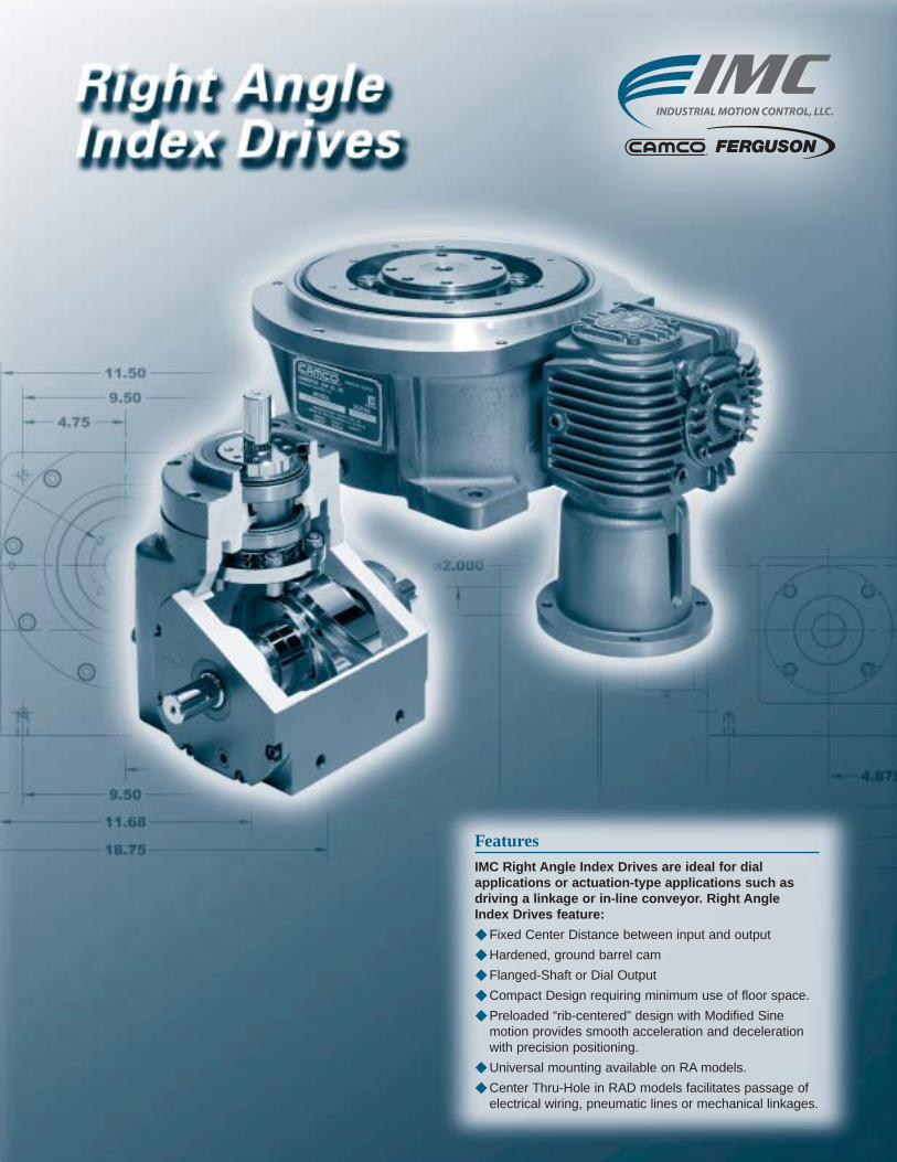
FeaturesIMC Right Angle Index Drives are ideal for dial applications or actuation-type applications such asdriving a linkage or in-line conveyor. Right Angle Index Drives feature:
◆ Fixed Center Distance between input and output
◆ Hardened, ground barrel cam
◆ Flanged-Shaft or Dial Output
◆ Compact Design requiring minimum use of floor space.
◆ Preloaded “rib-centered” design with Modified Sinemotion provides smooth acceleration and decelerationwith precision positioning.
◆ Universal mounting available on RA models.
◆ Center Thru-Hole in RAD models facilitates passage ofelectrical wiring, pneumatic lines or mechanical linkages.

Industrial Motion Control, L.L.C. • www.camcoindex.com • (847) 459-5200
F
F-2
Right Angle Index Drives
301RA
.125KWY
4X ø.312
.188KWY
6.12
.44
4.88
2X ø.500
8.44
1.88 1.88
.44
1.375
1.94
2.00 2.00
2.56
ø.625
1.25 4.88
2.19
1.97
.25
3.19
6.88
4.44
2.94
2.19
Technical SpecificationsOutput Load Capacity – loads carried during index
Radial 575 lbs
Thrust/Axial 577 lbs
Moment 719 in.-lbs
All dimensions are subject to change. For actual dimensions, please request the current drawing from IMC.
Accuracy ±67 arcsec / ±.0010" at 3" Radius
Repeatability ±33 arcsec / ±.0005" at 3" Radius
301RA Indexer Capacities
Other Motions (stops and index periods) available. Contact your lMC sales representative for more information.
Stops Index Motion B10 Capacity Internal Inertia Model (S) Period (β) at 50 RPM (in-lb) (lb-in2)
3270 ms 276 2 301RA3H14-270180 msc.33 331 2 301RA3H14-180 MSC.33
4270 ms 326 2 301RA4H14-270180 msc.33 412 2 301RA4H14-180 MSC.33270 ms 351 2 301RA6H14-270
6 180 ms 382 2 301RA6H14-180120 ms 390 2 301RA6H14-120270 ms 438 2 301RA8H14-270
8 180 ms 473 2 301RA8H14-180120 ms 481 2 301RA8H14-120
12270 ms 538 3 301RA12H14-270180 ms 597 3 301RA12H14-180270 ms 546 2 301RA16H14-270 II
16 180 ms 576 2 301RA16H14-180 II120 ms 220 2 301RA16H14-120 II270 ms 632 3 301RA24H14-270 II
24 180 ms 705 3 301RA24H14-180 II120 ms 773 3 301RA24H14-120 II

Industrial Motion Control, L.L.C. • www.camcoindex.com • (847) 459-5200
F
F-3
Right Angle Index Drives
1.90
1.30
ø3.88
9.22
5.19
ø19MM
3.44
3.64
ø14MM
2.00
1/3 HP MOTOR1900RPM, 90 VOLT D.C.
FOR INITIAL SETUP
R180GEAR REDUCER
IEC 71B14
REMOVABLE HANDWHEEL
1.75
◆ R180 Reducer (ratios from 5:1 to 60:1)– Double Extended Worm Shaft (Input)– Worm Shaft Handwheel
◆ Double Extended Camshaft (Input Shaft)
Standard Package301RA with
◆ 1/3 hp DC motor◆ Varipak DC Motor Control (up to 30 cpm)◆ Cycle Cam and Limit Switch Mounted to Camshaft◆ Right Hand Cam
◆ 1/3 or 1 hp AC Drive Package with Inverter Duty Motor and Inverter Drive (up to 60 cpm)
◆ Output Overload Clutch Models: .39F, .39FC, .39S, .39C, .39FC-SD, .39S-SD, .39C-SD– Available Settings (in-lb): 160, 210, 270, 320, 390
◆ Dual Cycle Cam and Limit Switch
All dimensions are subject to change.
For actual dimensions, please request
the current drawing from IMC.
Accessories and Options
◆ Finished cover for ceiling mount or tooling plate mounting
◆ Electric Clutch-Brake◆ Left Hand Cam◆ Relief in Dwell for shot-pin applications

Industrial Motion Control, L.L.C. • www.camcoindex.com • (847) 459-5200
F
F-4
Right Angle Index Drives
400RA
8X .312-18UNC X .62
5.62
.62
ø2.81
1.53
2.062
1.937
KWY.188
2X ø.875
3.34
9.75
3.34
45°
4X .312-24UNF
2X ø.219
2.88
2.38
4.75
5.75
ø
2.00
9.78
.03
2.062
5.38
6.62
.250KWY
ø2.000
.384.62
Technical SpecificationsOutput Load Capacity – loads carried during index
Radial 1473 lbs
Thrust/Axial 1406 lbs
Moment 2945 in.-lbs
All dimensions are subject to change. For actual dimensions, please request the current drawing from IMC.
Accuracy ±48 arcsec / ±.0007" at 3" Radius
Repeatability ±24 arcsec / ±.0003" at 3" Radius
400RA Indexer Capacities
Other Motions (stops and index periods) available. Contact your lMC sales representative for more information.
Stops Index Motion B10 Capacity Internal Inertia Model (S) Period (β) at 50 RPM (in-lb) (lb-in2)2 330 ms 595 15 400RA2H20-3303 270 ms 1591 15 400RA3H24-270
4270 ms 1858 15 400RA4H24-270180 ms 2098 15 400RA4H24-180270 ms 1711 15 400RA6H24-270
6 180 ms 1906 15 400RA6H24-180120 ms 2024 15 400RA6H24-120270 ms 1987 15 400RA8H24-270
8 180 ms 2194 15 400RA8H24-180120 ms 2354 15 400RA8H24-120270 ms 1290 15 400RA12H20-270
12 180 ms 1438 15 400RA12H20-180120 ms 1568 15 400RA12H20-120
16270 ms 1426 15 400RA16H20-270 II180 ms 2947 15 400RA16H24-180 II
24270 ms 1640 15 400RA24H20-270 II180 ms 1894 15 400RA24H20-180 II

F
Right Angle Index Drives
Industrial Motion Control, L.L.C. • www.camcoindex.com • (847) 459-5200 F-5
1.90
1.30
ø3.88
9.22
5.81
3.44
ø19MM
3.64
5.47 2.00
ø14MM
IEC 71B14
1900RPM, 90 VOLT D.C.1/3 HP MOTOR
R180
FOR INITIAL SETUP
GEAR REDUCER
REMOVABLE HANDWHEEL
1.75
◆ R180 Reducer (ratios from 5:1 to 60:1)– Double Extended Worm Shaft (Input)– Worm Shaft Handwheel
◆ Double Extended Camshaft (Input Shaft)
Standard Package400RA with
◆ 1/3 hp DC motor◆ Varipak DC Motor Control (up to 30 cpm)◆ Cycle Cam and Limit Switch Mounted to Camshaft◆ Right Hand Cam
◆ 1/3 or 1 hp AC Drive Package with Inverter Duty Motor and Inverter Drive (up to 60 cpm)
◆ R225 Reducer (ratios from 5:1 to 60:1)– 1 hp DC Motor– 56C Motor Adapter and Coupling
◆ Output Overload Clutch Models: 2.3F, 2.3FC, 2.3S, 2.3C, 2.3FC-SD, 2.3S-SD, 2.3C-SD– Available Settings (in-lb): 400, 600, 700, 850,
1000, 1300, 1800, 2000, 2300
All dimensions are subject to change.
For actual dimensions, please request
the current drawing from IMC.
Accessories and Options
◆ Dual Cycle Cam and Limit Switch◆ Finished cover for ceiling mount or tooling
plate mounting◆ Electric Clutch-Brake◆ Air Clutch-Brake (with R225 only)◆ Left Hand Cam◆ Relief in Dwell for shot-pin applications◆ 180-IOC or 225-IOC Input Overload Clutch
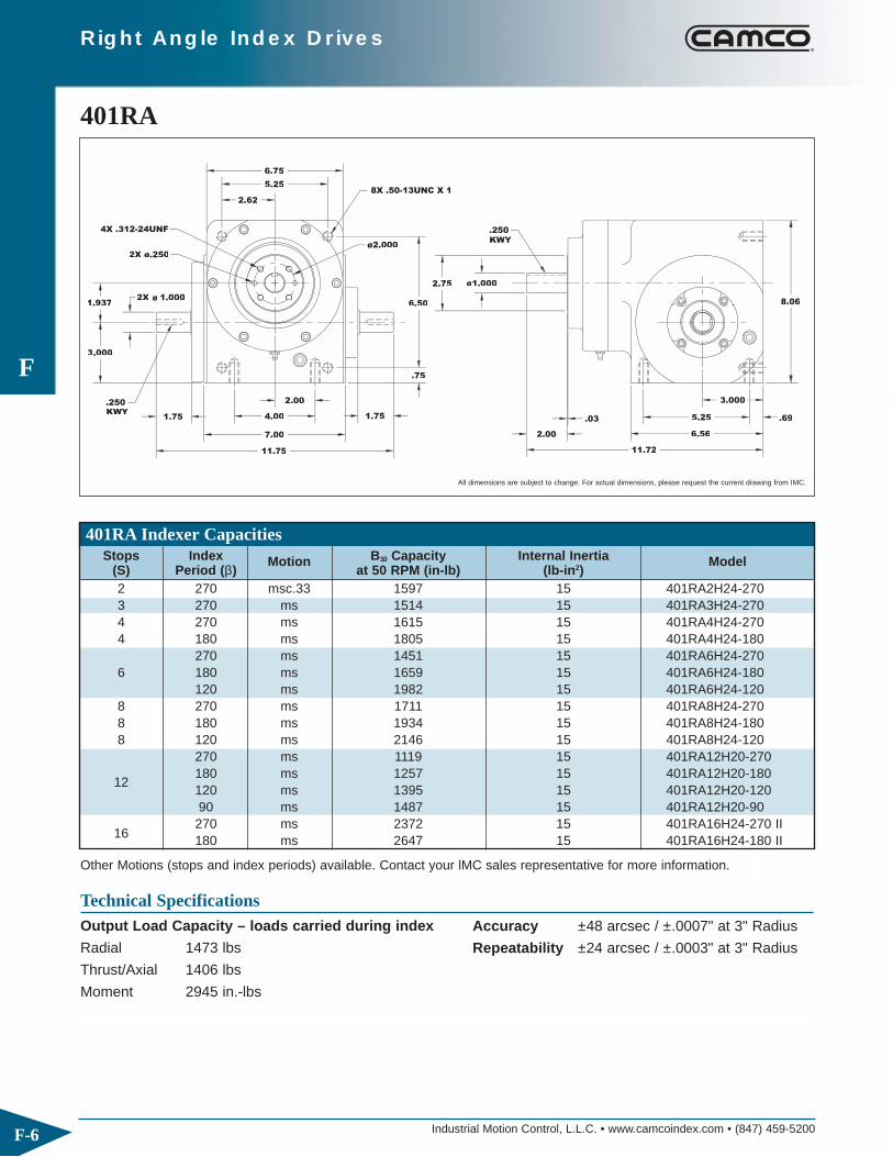
Industrial Motion Control, L.L.C. • www.camcoindex.com • (847) 459-5200
F
F-6
Right Angle Index Drives
401RA
2.75
8X .50-13UNC X 1
.250KWY
1.75
1.937
.0003
1.000ø2X
2.00
11.75
7.00
4.00 1.75
.75
6.50
4X .312-24UNF
2X ø.250
6.75
5.25
2.62
ø2.000
ø1.000
2.00
11.72
.03
3.000
.69
6.56
5.25
8.06
.250KWY
Technical SpecificationsOutput Load Capacity – loads carried during index
Radial 1473 lbs
Thrust/Axial 1406 lbs
Moment 2945 in.-lbs
All dimensions are subject to change. For actual dimensions, please request the current drawing from IMC.
Accuracy ±48 arcsec / ±.0007" at 3" Radius
Repeatability ±24 arcsec / ±.0003" at 3" Radius
401RA Indexer Capacities
Other Motions (stops and index periods) available. Contact your lMC sales representative for more information.
Stops Index Motion B10 Capacity Internal Inertia Model (S) Period (β) at 50 RPM (in-lb) (lb-in2)2 270 msc.33 1597 15 401RA2H24-2703 270 ms 1514 15 401RA3H24-2704 270 ms 1615 15 401RA4H24-2704 180 ms 1805 15 401RA4H24-180
270 ms 1451 15 401RA6H24-2706 180 ms 1659 15 401RA6H24-180
120 ms 1982 15 401RA6H24-1208 270 ms 1711 15 401RA8H24-2708 180 ms 1934 15 401RA8H24-1808 120 ms 2146 15 401RA8H24-120
270 ms 1119 15 401RA12H20-270
12180 ms 1257 15 401RA12H20-180120 ms 1395 15 401RA12H20-12090 ms 1487 15 401RA12H20-90270 ms 2372 15 401RA16H24-270 II
16 180 ms 2647 15 401RA16H24-180 II
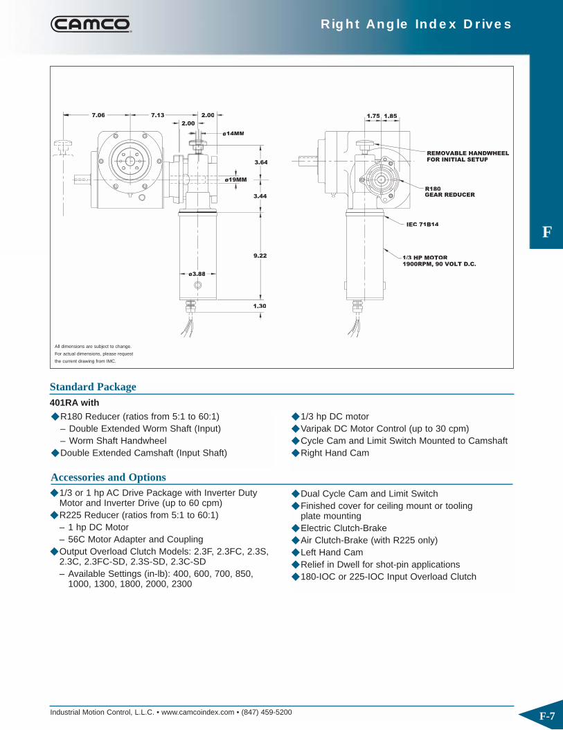
Industrial Motion Control, L.L.C. • www.camcoindex.com • (847) 459-5200
F
F-7
Right Angle Index Drives
1.857.137.06
1.30
FOR INITIAL SETUP
R180GEAR REDUCER
REMOVABLE HANDWHEEL
1/3 HP MOTOR1900RPM, 90 VOLT D.C.
IEC 71B14
ø14MM
øø3.88
9.22
ø19MM
3.44
3.64
2.00
2.00 1.75
◆ R180 Reducer (ratios from 5:1 to 60:1)– Double Extended Worm Shaft (Input)– Worm Shaft Handwheel
◆ Double Extended Camshaft (Input Shaft)
Standard Package401RA with
◆ 1/3 hp DC motor◆ Varipak DC Motor Control (up to 30 cpm)◆ Cycle Cam and Limit Switch Mounted to Camshaft◆ Right Hand Cam
◆ 1/3 or 1 hp AC Drive Package with Inverter Duty Motor and Inverter Drive (up to 60 cpm)
◆ R225 Reducer (ratios from 5:1 to 60:1)– 1 hp DC Motor– 56C Motor Adapter and Coupling
◆ Output Overload Clutch Models: 2.3F, 2.3FC, 2.3S, 2.3C, 2.3FC-SD, 2.3S-SD, 2.3C-SD– Available Settings (in-lb): 400, 600, 700, 850,
1000, 1300, 1800, 2000, 2300
All dimensions are subject to change.
For actual dimensions, please request
the current drawing from IMC.
Accessories and Options
◆ Dual Cycle Cam and Limit Switch◆ Finished cover for ceiling mount or tooling
plate mounting◆ Electric Clutch-Brake◆ Air Clutch-Brake (with R225 only)◆ Left Hand Cam◆ Relief in Dwell for shot-pin applications◆ 180-IOC or 225-IOC Input Overload Clutch

Industrial Motion Control, L.L.C. • www.camcoindex.com • (847) 459-5200
F
F-8
Right Angle Index Drives
512RA
ø3.38
2.25
2.375
3.500
2X ø1.375
14.00
8.25
6.50 2.25
3.25
1.00
7.50
8.00
6.00
3.00
ø1.625
3.50
* 14.50
.06
3.500
7.88
6.50 .69
9.44
* 14.93 FOR NON-STANDARD CAMS
8X .50-13UNC X1
KWY
.312
4X .375-24UNC
ø2.375
.375
KWY
Technical SpecificationsOutput Load Capacity – loads carried during index
Radial 3611 lbs
Thrust/Axial 2277 lbs
Moment 12,638 in.-lbs
All dimensions are subject to change. For actual dimensions, please request the current drawing from IMC.
Accuracy ±38 arcsec / ±.0011" at 6" Radius
Repeatability ±19 arcsec / ±.0006" at 6" Radius
512RA Indexer Capacities
Other Motions (stops and index periods) available. Contact your lMC sales representative for more information.
Stops Index Motion B10 Capacity Internal Inertia Model (S) Period (β) at 50 RPM (in-lb) (lb-in2)2 270 msc.33 2061 45 512RA2H32-270 MSC.33
3270 ms 2360 45 512RA3H32-270180 msc.33 2852 45 512RA3H32-180 MSC 0.33270 ms 2710 45 512RA4H32-270
4 180 msc.33 3430 45 512RA4H32-180 MSC 0.33120 msc.33 3648 45 512RA4H32-120 MSC 0.33270 ms 2613 45 512RA6H32-270
6 180 ms 2992 45 512RA6H32-180120 ms 3179 45 512RA6H32-120270 ms 3172 45 512RA8H32-270
8 180 ms 3529 45 512RA8H32-180120 ms 3802 45 512RA8H32-120270 ms 2738 45 512RA12H28-270
12 180 ms 3064 45 512RA12H28-180120 ms 3176 45 512RA12H28-120
16270 ms 4466 45 512RA16H32-270 II180 ms 4963 45 512RA16H32-180 II270 ms 3497 45 512RA24H28-270 II
24 180 ms 3977 45 512RA24H28-180 II120 ms 4347 45 512RA24H28-120 II

Industrial Motion Control, L.L.C. • www.camcoindex.com • (847) 459-5200
F
F-9
Right Angle Index Drives
ø.875
( ) = OPTIONAL
ø 5.25
ø6.62
12.25
8.12
7.50
7.56
1.69
1.622.75
90V DC 1725 RPM1HP MOTOR
4.63
6.88
2.25
(ø.688)
(4.81)3.31
2.75
ADAPTOR56C MOTOR
GEAR REDUCERR225
◆ R225 Reducer (ratios from 5:1 to 60:1)– 56C Motor Adapter and Coupling
◆ Double Extended Camshaft (Input Shaft)◆ 1 hp DC motor
Standard Package512RA with
◆ Varipak DC Motor Control (up to 30 cpm)◆ Cycle Cam and Limit Switch Mounted to Camshaft◆ Right Hand Cam
◆ 1 hp AC Drive Package with Inverter Duty Motor and Inverter Drive (up to 60 cpm)
◆ R260 Reducer (ratios from 5:1 to 60:1)– 56C Motor Adapter and Coupling
◆ Output Overload Clutch Models: 6.0F, 6.0FC, 6.0S and 6.0C, 6.0C-SD, 6.0FC-SD, 6.0S-SD– Available Settings (in-lb): 670, 825, 1100, 1400,
1700, 2000, 2300, 2500, 3000, 3800, 4000, 5000, 6000
All dimensions are subject to change.
For actual dimensions, please request
the current drawing from IMC.
Accessories and Options
◆ Dual Cycle Cam and Limit Switch◆ Finished cover for ceiling mount or tooling
plate mounting◆ Electric Clutch-Brake◆ Air Clutch-Brake◆ Left Hand Cam◆ Relief in Dwell for shot-pin applications◆ 225-IOC or 260-IOC Input Overload Clutch

Industrial Motion Control, L.L.C. • www.camcoindex.com • (847) 459-5200
F
F-10
Right Angle Index Drives
662RA
4X .500-13UNC X 1
KWY.375
4X .375-24UNF
ø3.250KWY.500
ø4.56
11.003.0002X ø1.625
2.84
4.875
2.849.50
18.75
11.68
4.75
1.06
9.50
4.75
11.50
13.12
* 20.88 FOR NON-STANDRD CAMS
4.56 .12
* 20.12
4.875
1.00
10.50
8.50
ø2.000
Technical SpecificationsOutput Load Capacity – loads carried during index
Radial 5167 lbs
Thrust/Axial 5239 lbs
Moment 23,562 in.-lbs
All dimensions are subject to change. For actual dimensions, please request the current drawing from IMC.
Accuracy ±36 arcsec / ±.001" at 6" Radius
Repeatability ±18 arcsec / ±.0005" at 6" Radius
662RA Indexer Capacities
Other Motions (stops and index periods) available. Contact your lMC sales representative for more information.
Stops Index Motion B10 Capacity Internal Inertia Model (S) Period (β) at 50 RPM (in-lb) (lb-in2)2 270 ms 6534 172 662RA2H48-270
3270 ms 5913 169 662RA3H40-270180 ms 6146 169 662RA3H40-180270 ms 6903 172 662RA4H40-270
4 180 ms 7616 172 662RA4H40-180120 ms 7751 172 662RA4H40-120270 ms 5734 169 662RA6H40-270
6 180 ms 6949 169 662RA6H40-180120 ms 7551 169 662RA6H40-120270 ms 7187 172 662RA8H40-270
8180 ms 8085 172 662RA8H40-180120 ms 8867 172 662RA8H40-12090 ms 8987 172 662RA8H40-90270 ms 4504 165 662RA12H32-270
12180 ms 5052 165 662RA12H32-180120 ms 5511 165 662RA12H32-12090 ms 5536 165 662RA12H32-90
16270 ms 9518 172 662RA16H40-270 II180 ms 10626 172 662RA16H40-180 II
24 270 ms 5846 165 662RA24H32-270 II
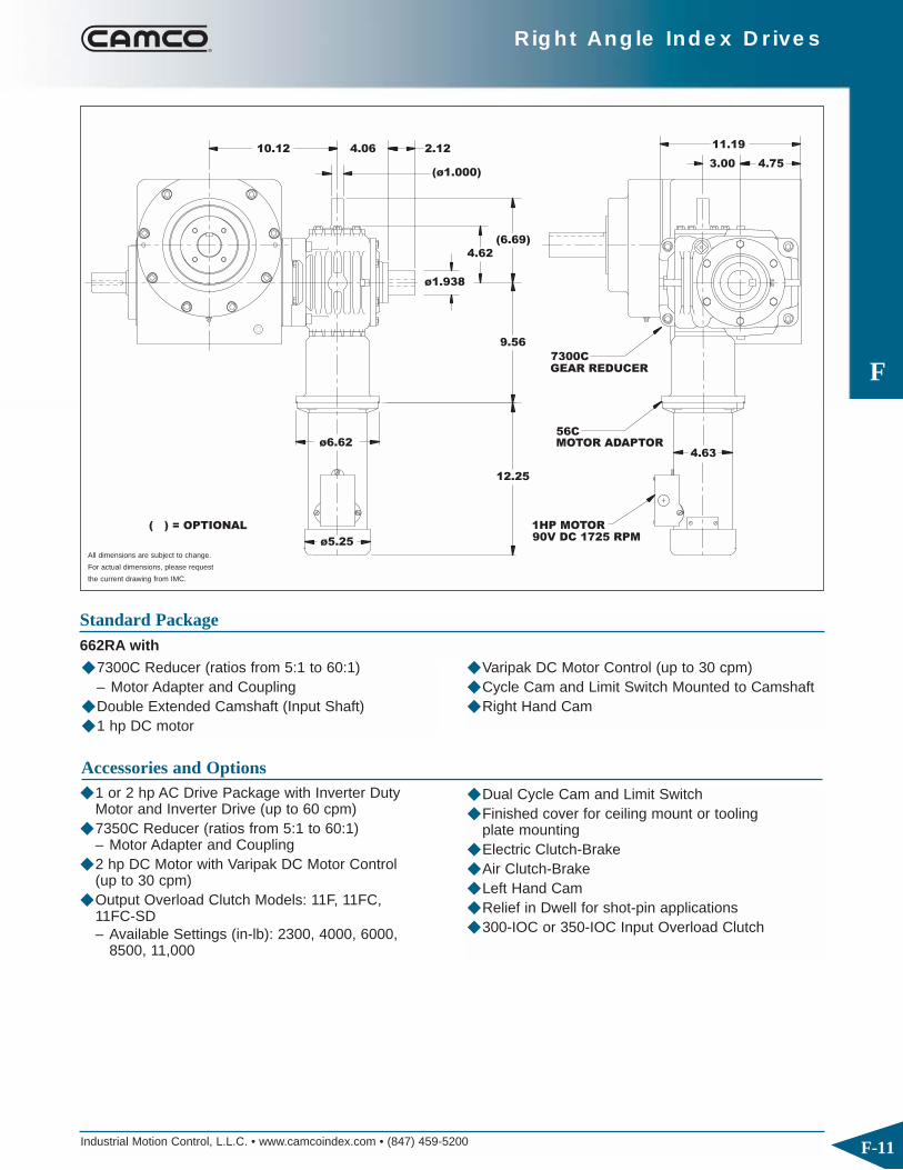
Industrial Motion Control, L.L.C. • www.camcoindex.com • (847) 459-5200
F
F-11
Right Angle Index Drives
GEAR REDUCER7300C
MOTOR ADAPTOR
90V DC 1725 RPM1HP MOTOR
56C
( ) = OPTIONAL
ø5.25
12.25
ø6.624.63
9.56
2.124.0610.12
(6.69)
4.62
ø1.938
(ø1.000)3.00 4.75
11.19
◆ 7300C Reducer (ratios from 5:1 to 60:1)– Motor Adapter and Coupling
◆ Double Extended Camshaft (Input Shaft)◆ 1 hp DC motor
Standard Package662RA with
◆ Varipak DC Motor Control (up to 30 cpm)◆ Cycle Cam and Limit Switch Mounted to Camshaft◆ Right Hand Cam
◆ 1 or 2 hp AC Drive Package with Inverter Duty Motor and Inverter Drive (up to 60 cpm)
◆ 7350C Reducer (ratios from 5:1 to 60:1)– Motor Adapter and Coupling
◆ 2 hp DC Motor with Varipak DC Motor Control (up to 30 cpm)
◆ Output Overload Clutch Models: 11F, 11FC, 11FC-SD– Available Settings (in-lb): 2300, 4000, 6000,
8500, 11,000
All dimensions are subject to change.
For actual dimensions, please request
the current drawing from IMC.
Accessories and Options
◆ Dual Cycle Cam and Limit Switch◆ Finished cover for ceiling mount or tooling
plate mounting◆ Electric Clutch-Brake◆ Air Clutch-Brake◆ Left Hand Cam◆ Relief in Dwell for shot-pin applications◆ 300-IOC or 350-IOC Input Overload Clutch

Industrial Motion Control, L.L.C. • www.camcoindex.com • (847) 459-5200
F
F-12
Right Angle Index Drives
663RAD
3.56
6X .500-13UNC
2X ø1.438
.375KWY
9.75
5.50
"A"
13.009.75
4X ø.562
3.25
5.50
6.50
12.50
6.25
.75
4.12
.188
.12
.25
7.50
ø15.25
ø12.748
2X ø.5000 X 1.00
4X .500-20UNF X 1.00
13.25
11.62
4.38
6X .375-24UNF X .88
ø11.00
ø5.000
3.125
1.00
R5.94
.64
ø14.000
ø4.250
ø8.375
DRAWING FOR ANGULAR LOCATIONREQUEST CAMCO CERTIFIED
Technical SpecificationsOutput Load Capacity – loads carried during index
Radial 6843 lbs
Thrust/Axial 4721 lbs
Moment 37,637 in.-lbs
All dimensions are subject to change. For actual dimensions, please request the current drawing from IMC.
Accuracy ±36 arcsec / ±.001" at 6" Radius
Repeatability ±18 arcsec / ±.0005" at 6" Radius
663RAD Indexer Capacities
Other Motions (stops and index periods) available. Contact your lMC sales representative for more information.
Stops Index Motion B10 Capacity Internal Inertia Model (S) Period (β) at 50 RPM (in-lb) (lb-in2)
3270 ms 3194 636 663RAD3H36-270180 ms 3199 636 663RAD3H36-180
4270 ms 3593 642 663RAD4H36-270180 ms 4091 638 663RAD4H32-180270 ms 3662 636 663RAD6H36-270
6 180 ms 4057 636 663RAD6H36-180120 ms 4187 636 663RAD6H36-120270 ms 4347 642 663RAD8H36-270
8 180 ms 4730 642 663RAD8H36-180120 ms 4973 642 663RAD8H32-120270 ms 5200 647 663RAD12H32-270
12180 ms 5757 647 663RAD12H32-180120 ms 6167 647 663RAD12H32-12090 ms 4211 635 663RAD12H28-90270 ms 3977 635 663RAD16H24-270
16 180 ms 4445 635 663RAD16H24-180120 ms 4945 635 663RAD16H24-120270 ms 7145 647 663RAD24H32-270 II
24 180 ms 7306 647 663RAD24H32-180 II120 ms 8269 647 663RAD24H32-120 II

Industrial Motion Control, L.L.C. • www.camcoindex.com • (847) 459-5200
F
F-13
Right Angle Index Drives
90V DC 1725 RPM1HP MOTOR
GEAR REDUCERR225
MOTOR ADAPTOR56C
(4.81)
12.25
7.50
9.94
(ø.688)
2.751.62
3.31
ø.875
ø6.62
ø5.25
( ) = OPTIONAL 6.88
2.75 2.25.56
4.63
◆ R225 Reducer (ratios from 5:1 to 60:1)– 56C Motor Adapter and Coupling
◆ 1 hp DC motor◆ Varipak DC Motor Control (up to 30 cpm)
Standard Package663RAD with
◆ Cycle Cam and Limit Switch Mounted to Camshaft◆ Double Extended Camshaft (Input Shaft)◆ Center Through Hole (.64 in. Diameter) ◆ Right Hand Cam
◆ 1 hp AC Drive Package with Inverter Duty Motor and Inverter Drive (up to 60 cpm)
◆ R260 Reducer (ratios from 5:1 to 60:1)– 56C Motor Adapter and Coupling
◆ Output Overload Clutch Models: 11F, 11FC, 11FC-SD– Available Settings (in-lb): 2300, 4000, 6000,
8500, 11,000◆ Output Overload Clutch Model: 7.8D
– Available Settings (in-lb): 1400, 1700, 2600, 3200, 4200, 5000, 7200, 10,000
◆ “Super Accurate” Output Overload Clutch Model 7.8D-SA– Adjustable Setting: 2600-10,000 in-lb.
All dimensions are subject to change.
For actual dimensions, please request
the current drawing from IMC.
Accessories and Options
◆ Dual Cycle Cam and Limit Switch◆ Finished cover for ceiling mount or tooling
plate mounting◆ Electric Clutch-Brake◆ Air Clutch-Brake◆ Left Hand Cam◆ Relief in Dwell for shot-pin applications◆ 225-IOC or 260-IOC Input Overload Clutch

Industrial Motion Control, L.L.C. • www.camcoindex.com • (847) 459-5200
F
F-14
Right Angle Index Drives
900RAD
KWY.375
6X .50-20UNF
4X .500-20UNF
6X .500-13UNC
4X ø.562
ø9.000
2X ø1.625
ø4.250
5.385.38
19.56
13.88
6.12 6.12
ø15.500
ø14.000
4.3125 13.62
.19
ø5.000
4.62
ø11.50
10.38
11.56
4.75
1.00
9.75
ø
R6.25
R8.50
35°
35°
Technical SpecificationsOutput Load Capacity – loads carried during index
Radial 4956 lbs
Thrust/Axial 2940 lbs
Moment 28,496 in.-lbs
All dimensions are subject to change. For actual dimensions, please request the current drawing from IMC.
Accuracy ±27 arcsec / ±.0008" at 6" Radius
Repeatability ±13 arcsec / ±.0004" at 6" Radius
900RAD Indexer Capacities
Other Motions (stops and index periods) available. Contact your lMC sales representative for more information.
Stops Index Motion B10 Capacity Internal Inertia Model (S) Period (β) at 50 RPM (in-lb) (lb-in2)2 330 msc.50 10260 1048 900RAD2H48-330 MSC 0.5
3270 ms 10599 1048 900RAD3H48-270180 ms 7966 1002 900RAD3H40-180
4270 ms 10653 1076 900RAD4H48-270180 ms 10016 1076 900RAD4H48-180270 ms 11764 1076 900RAD6H48-270
6 180 ms 12946 1048 900RAD6H48-180120 ms 13518 1076 900RAD6H48-120270 ms 13467 1076 900RAD8H48-270
8 180 ms 14969 1076 900RAD8H48-180120 ms 16095 1076 900RAD8H48-120270 ms 16009 1132 900RAD12H48-270
12180 ms 13634 1056 900RAD12H40-180120 ms 14756 1056 900RAD12H40-12090 ms 15518 1056 900RAD12H40-90270 ms 7152 1037 900RAD16H32-270
16 180 ms 7990 1037 900RAD16H32-180120 ms 8682 1037 900RAD16H32-120
24270 ms 22349 1132 900RAD24H48-270 II180 ms 18636 1056 900RAD24H40-180 II

Industrial Motion Control, L.L.C. • www.camcoindex.com • (847) 459-5200
F
F-15
Right Angle Index Drives
4.62
11.25
(ø1.000)
2.154.06
ø 1.938
REDUCERGEAR7300C
90V DC 1725 RPM1HP MOTOR
ø6.62
ADAPTORMOTOR56C
ø 5.25
( ) = OPTIONAL11.19
4.79
3.00
4.75
(6.69)
9.56
12.25
4.63
◆ 7300C Reducer (ratios from 5:1 to 60:1)– Motor Adapter and Coupling
◆ 1 hp DC motor◆ Varipak DC Motor Control (up to 30 cpm)
Standard Package900RAD with
◆ Cycle Cam and Limit Switch Mounted to Camshaft◆ Center Through Hole (1.56 in. Diameter)◆ Double Extended Camshaft (Input Shaft)◆ Right Hand Cam
◆ 1 or 2 hp AC Drive Package with Inverter Duty Motor and Inverter Drive (up to 60 cpm)
◆ 7350C Reducer (ratios from 5:1 to 60:1)– Motor Adapter and Coupling
◆ 2 hp DC Motor with Varipak DC Motor Control (up to 30 cpm)
◆ Output Overload Clutch Model: 7.8D– Available Settings (in-lb): 1400, 1700, 2600,
3200, 4200, 5000, 7200, 10,000◆ Output Overload Clutch Model: 18D
– Available Settings (in-lb): 5000, 7000, 7800, 10,000, 12,000, 16,000, 19,000, 21,000, 27,000, 42,000, 45,000
All dimensions are subject to change.
For actual dimensions, please request
the current drawing from IMC.
Accessories and Options
◆ Dual Cycle Cam and Limit Switch◆ Finished cover for ceiling mount or tooling
plate mounting◆ Electric Clutch-Brake◆ Air Clutch-Brake◆ Left Hand Cam◆ Relief in Dwell for shot-pin applications◆ 300-IOC or 350-IOC Input Overload Clutch

F
F-16
Right Angle Index Drives
1200RAD
ø6.000
ø2.00 THRU
6.12
10.62
7.84
KWY.625
ø2.500
6X .500-13UNC
2X
ø8.25
24.75
10.62
7.84
6.12
ø20.75
19.250ø
17.00ø
14.38
3.62
5.688
ANGULAR LOCATION
DRAWING FOR
REQUEST CERTIFIED8X .500-13UNC
22.50°"A"
.38 11.56
10.31
1.00
10.5511.62
R11.00
4.62
Technical SpecificationsOutput Load Capacity – loads carried during index
Radial 7110 lbs
Thrust/Axial 4138 lbs
Moment 60,438 in.-lbs
All dimensions are subject to change. For actual dimensions, please request the current drawing from IMC.
1200RAD Indexer Capacities
Other Motions (stops and index periods) available. Contact your lMC sales representative for more information.
Stops Index Motion B10 Capacity Internal Inertia Model (S) Period (β) at 50 RPM (in-lb) (lb-in2)3 270 msc.33 26935 4458 1200RAD3H64-270 MSC.33
4270 ms 29164 4675 1200RAD4H64-270180 msc.50 35864 4675 1200RAD4H64-180 MSC.50
6270 ms 26972 4563 1200RAD6H64-270180 ms 29579 4563 1200RAD6H64-180270 ms 30963 4675 1200RAD8H64-270
8 180 ms 34386 4675 1200RAD8H64-180120 ms 27990 4514 1200RAD8H56-120270 ms 36568 4899 1200RAD12H64-270
12180 ms 30667 4685 1200RAD12H56-180120 ms 33436 4685 1200RAD12H56-12090 ms 24799 4524 1200RAD12H48-90270 ms 21934 4623 1200RAD16H48-270
16 180 ms 24567 4623 1200RAD16H48-180120 ms 20574 4900 1200RAD16H40-120
24 270 ms 51080 4899 1200RAD24H64-270 II
Accuracy ±20 arcsec / ±.0006" at 6" Radius
Repeatability ±10 arcsec / ±.0003" at 6" Radius

Industrial Motion Control, L.L.C. • www.camcoindex.com • (847) 459-5200
F
F-17
Right Angle Index Drives
7300CGEAR
4.41
REDUCER
(ø1.000)
12.22 4.06
1HP MOTOR90V DC 1725 RPM
ø 5.25
4.44( ) = OPTIONAL
(6.69)
9.56
ø2.500
4.62
3.00
5.12
6.41
12.25
56CMOTORADAPTOR
4.63
ø6.62
◆ 7300C Reducer (ratios from 5:1 to 60:1)– Motor Adapter and Coupling
◆ 1 hp DC motor◆ Varipak DC Motor Control (up to 30 cpm)
Standard Package1200RAD with
◆ Cycle Cam and Limit Switch Mounted to Camshaft◆ Center Through Hole (2.00 in. Diameter)◆ Double Extended Camshaft (Input Shaft)◆ Right Hand Cam
◆ 1 or 2 hp AC Drive Package with Inverter Duty Motor and Inverter Drive (up to 60 cpm)
◆ 7350C Reducer (ratios from 5:1 to 60:1)– Motor Adapter and Coupling
◆ 2 hp DC Motor with Varipak DC Motor Control (up to 30 cpm)
◆ Output Overload Clutch Model: 31D– Available Settings (in-lb): 8500, 13,000, 20,000,
31,000
All dimensions are subject to change.
For actual dimensions, please request
the current drawing from IMC.
Accessories and Options
◆ Dual Cycle Cam and Limit Switch◆ Finished cover for ceiling mount or tooling
plate mounting◆ Electric Clutch-Brake◆ Air Clutch-Brake◆ Left Hand Cam◆ Relief in Dwell for shot-pin applications◆ 300-IOC or 350-IOC Input Overload Clutch

Industrial Motion Control, L.L.C. • www.camcoindex.com • (847) 459-5200
F
F-18
Right Angle Index Drives
1. Model
2. Input Shaft Configuration ◆ Side 1◆ Side 2◆ Double Input – DI (Standard)
Indexer Ordering Procedure3. Cam Lead (Helix)
◆ Right Hand (standard)◆ Left Hand
NOTE: Input may rotate in either direction to achievedesired direction of output rotation
4. Indexer Mounting Position: 1-6
Indexer Mounting Position Indexer Mounting Position
Input
Input
AE: Input Shaft AS: Output Shaft AS: Output ShaftAE: Input Shaft
Position of Shafts Position of Shafts
6
4
2 1
3
5 5 6
3 4
1 2
AE
ASAS
AE
ASAEAS
AE
AS
AE
AS
AE
AS
AS
AS
AE
AEAE
AE
AS
AEAE
AS
AS
RA RAD
Right Hand Left Hand
2 DI 1
Right Hand Left Hand
2 DI 1
RA RAD
(Standard)
(Standard)
Cam Lead Cam Lead
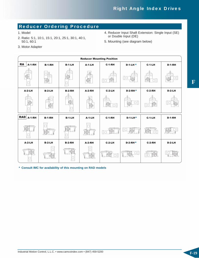
Industrial Motion Control, L.L.C. • www.camcoindex.com • (847) 459-5200
F
F-19
Right Angle Index Drives
1. Model
2. Ratio: 5:1, 10:1, 15:1, 20:1, 25:1, 30:1, 40:1, 50:1, 60:1
3. Motor Adapter
Reducer Ordering Procedure4. Reducer Input Shaft Extension: Single Input (SE)
or Double Input (DE)
5. Mounting (see diagram below)
Reducer Mounting Position
A-1-RH B-1-RH B-1-LH A-1-LH C-1-RH D-1-LH C-1-LH D-1-RH
A-2-LH B-2-LH B-2-RH A-2-RH C-2-LH D-2-RH C-2-RH D-2-LH
B-2-LHA-2-LH B-2-RH
B-1-RHA-1-RH B-1-LH
C-2-LHA-2-RH D-2-RH
C-1-RHA-1-LH D-1-LH
C-2-RH D-2-LH
C-1-LH D-1-RH
RA
RAD
*
*
*
*
* Consult IMC for availability of this mounting on RAD models

Industrial Motion Control, L.L.C. • www.camcoindex.com • (847) 459-5200
F
F-20
Right Angle Index Drives

FeaturesThe E-Series Index Drive is ideal for heavy-duty rotarydial applications with features including:
◆ Large output mounting surface supported by a 4-pointcontact bearing superior thrust and moment capacity
◆ Large center thru hole to accommodate stationary center post, electrical wiring and air or hydraulic lines
◆ Complete motorized drive package with reducer andbrake-motor combinations to suit most applications
◆ Precision cam with preloaded cam followers for maximum accuracy
◆ Durable welded steel housing
◆ Preloaded “center rib” design for smooth accelerationand deceleration with precision positioning

Industrial Motion Control, L.L.C. • www.camcoindex.com • (847) 459-5200
G
G-2
Heavy Duty E-Series Index Drives
750E
ø
405
15°
330.2
(6)
ø65h6 (KH87)
ø2.750"(7500C)ø75h6 (KH97)
159.6
452
360
159.6
31
174
120.6
120.6
( ) = OPTIONAL
810 (KH97)( )
505
22.5°
480
684 (KH87)( )
347
2X 20.5
315
347
315
12X M16 X 30
6X ø20.5
5X 45°
(ø220) ø127
691 (7500C)( )
8X M16 X 30
R370
ø740
R340ø570
Technical SpecificationsOutput Load Capacity – loads carried during index
Radial 29,200 lbs
Thrust/Axial 42,000 lbs
Moment 419,500 in-lb
All dimensions are subject to change. For actual dimensions, please request the current drawing from IMC.
Typical Application Dial Diameter: 55 in. to 110 in.
Accuracy ±27 arcsec / ±.002" at 15" radius
Repeatability ±13 arcsec / ±.0009" at 15" radius
750E Indexer Capacities
Other Motions (stops and index periods) available. Contact your lMC sales representative for more information.
Stops Index Motion B10 Capacity Internal Inertia Model (S) Period (β) at 50 RPM (in-lb) (lb-in2)2 330 msc.33 48,321 51,904 750E2H80-3303 330 msc.50 84,296 52,588 750E3H80-3304 330 msc.12 78,632 52,588 750E4H80-3305 330 ms 75,358 52,246 750E5H80-3306 330 ms 88,898 52,588 750E6H80-3307 330 ms 113,457 52,929 750E7H80-3308 330 ms 123,325 53,271 750E8H80-33010 330 ms 76,199 52,246 750E10H80-33012 330 ms 87,350 52,588 750E12H80-33016 330 ms 132,131 53,271 750E16H80-33024 330 ms 116,378 52,588 750E24H80-330

Industrial Motion Control, L.L.C. • www.camcoindex.com • (847) 459-5200
G
G-3
Heavy Duty E-Series Index Drives
(OPTIONAL BRAKE)
690
520
"DM"
126
174212
ø65
133
257
25.9
"LB"
"LM"
IEC80
IEC160L
IEC132M
IEC180
IEC160M
IEC132S
IEC112
IEC90
IEC100
MOTOR FRAME
64249145
156488331
112402275
156
112
560
441
331
275
80
80
375
349
221
221
269
319
197
197
"LM""DM"
85
85
"LB"
GEARMOTOR
SEW KH87
◆ KH87 Gear Reducer with Brake-motor◆ Double Extended Camshaft (Input shaft)◆ Center Thru Hole (127 mm)
Standard Package750E Indexer with
◆ Cycle Cam & limit Switch◆ Right Hand Cam
Optional Accessories
All dimensions are subject to change. For actual dimensions, please request the
current drawing from IMC.
◆ Left Hand Cam◆ Relief in Dwell for Shot-Pin applications◆ Dual Cam & limit Switch◆ KH97 Gear Reducer with Brake-motor
◆ Digi-Dog programmable rotary Limit Switch◆ Stationary Center Post◆ Visual Disk Dwell Indicator

Industrial Motion Control, L.L.C. • www.camcoindex.com • (847) 459-5200
G
G-4
Heavy Duty E-Series Index Drives
950E
460 460
764 (KH87) ( ) = OPTIONAL828 (KH97)
195
355355
435 435
464
ø60
6X M16 X 322X ø19
2X ø20.6
17370
237
130
130
ø75 (KH97)ø65 (KH87)
245
405
8X M16 X 32
6X M6 X 12ø750ø
5X ø20.6
R432.5
R410R465
105ø
940ø
ø( 200)
(6.5) 500
4X 45°
Technical SpecificationsOutput Load Capacity – loads carried during index
Radial 52,600 lbs
Thrust/Axial 75,850 lbs
Moment 977,500 in-lb
All dimensions are subject to change. For actual dimensions, please request the current drawing from IMC.
Typical Application Dial Diameter: 70 in. to 140 in.
Accuracy ±24 arcsec / ±.0023" at 20" radius
Repeatability ±12 arcsec / ±.0012" at 20" radius
950E Indexer Capacities
Other Motions (stops and index periods) available. Contact your lMC sales representative for more information.
Stops Index Motion B10 Capacity Internal Inertia Model (S) Period (β) at 50 RPM (in-lb) (lb-in2)2 330 msc0.50 76,483 129,000 950E2H80-330 3 330 msc0.50 141,666 142,900 950E3H96-330 4 330 ms 115,358 142,900 950E4H96-3306 330 msc0.33 173,199 142,900 950E6H96-3308 330 ms 120,209 120,600 950E8H96-33012 330 ms 156,333 142,900 950E12H96-33016 330 ms 88,617 120,600 950E16H80-33018 330 ms 181,002 120,600 950E18H96-330 II24 330 ms 197,655 142,900 950E24H96-330 II

G
Heavy Duty E-Series Index Drives
Industrial Motion Control, L.L.C. • www.camcoindex.com • (847) 459-5200 G-5
"LB"
85
85
"DM" "LM"
IEC100
IEC90
197
197
319
269
IEC112
IEC132S
221
221
349
375
80
80
IEC160M
IEC180
275
331
441
560
112
156
IEC132M 275 402 112
IEC160L 331 488 156
IEC80 145 249 64
(OPTIONAL BRAKE)
MOTOR FRAME
"LM"
"LB"
"DM"
237
25.9
257
133
ø 65 h6
601
771
212
126
SEW KH87
GEARMOTOR
◆ KH87 Gear Reducer with Brake-motor◆ Double Extended Camshaft (Input shaft)◆ Center Thru Hole (105 mm)
Standard Package950E Indexer with
◆ Cycle Cam & limit Switch◆ Right Hand Cam
Optional Accessories
All dimensions are subject to change. For actual dimensions, please request the
current drawing from IMC.
◆ Left Hand Cam◆ Relief in Dwell for Shot-Pin applications◆ Dual Cam & limit Switch◆ KH97 Gear Reducer with Brake-motor
◆ Digi-Dog Programmable Rotary Limit Switch◆ Stationary Center Post◆ Visual Disk Dwell Indicator
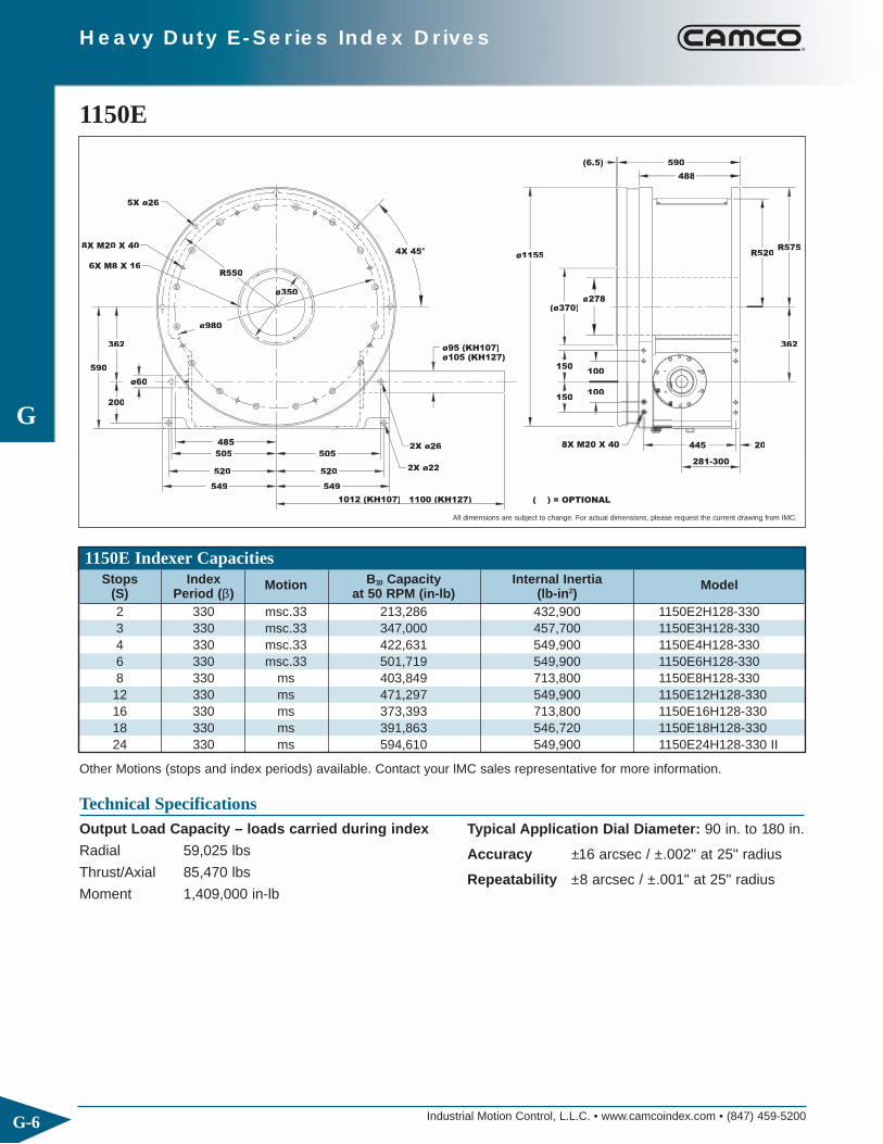
Industrial Motion Control, L.L.C. • www.camcoindex.com • (847) 459-5200
G
G-6
Heavy Duty E-Series Index Drives
1150E
1100 (KH127)
549
ø980
590
ø60
200
362
549
520
505
520
505
1012 (KH107)( )
R550
ø350
4X 45°
( ) = OPTIONAL
ø105 (KH127)ø95 (KH107)
150100
150100
20
362
ø1155
ø278
(6.5)
R575R520
590
488
2X ø22
2X ø26
5X ø26
6X M8 X 16
8X M20 X 40
8X M20 X 40
(ø370)
Technical SpecificationsOutput Load Capacity – loads carried during index
Radial 59,025 lbs
Thrust/Axial 85,470 lbs
Moment 1,409,000 in-lb
All dimensions are subject to change. For actual dimensions, please request the current drawing from IMC.
Typical Application Dial Diameter: 90 in. to 180 in.
Accuracy ±16 arcsec / ±.002" at 25" radius
Repeatability ±8 arcsec / ±.001" at 25" radius
1150E Indexer Capacities
Other Motions (stops and index periods) available. Contact your lMC sales representative for more information.
Stops Index Motion B10 Capacity Internal Inertia Model (S) Period (β) at 50 RPM (in-lb) (lb-in2)2 330 msc.33 213,286 432,900 1150E2H128-330 3 330 msc.33 347,000 457,700 1150E3H128-330 4 330 msc.33 422,631 549,900 1150E4H128-330 6 330 msc.33 501,719 549,900 1150E6H128-330 8 330 ms 403,849 713,800 1150E8H128-33012 330 ms 471,297 549,900 1150E12H128-33016 330 ms 373,393 713,800 1150E16H128-33018 330 ms 391,863 546,720 1150E18H128-33024 330 ms 594,610 549,900 1150E24H128-330 II

Industrial Motion Control, L.L.C. • www.camcoindex.com • (847) 459-5200
G
G-7
Heavy Duty E-Series Index Drives
MOTOR FRAME
315
1851037
780
.81
52
528
630
ø95 h6
"LB"
"LM"
341
198
(321-340)
"DM"
OPTIONAL BRAKE
GEARMOTORSEW KH107
156690394IEC225
156488331IEC160L
112402275IEC132M
156608394IEC200
156
112
560
441
331
275
IEC180
IEC160M
80
80
375
349
221
221
IEC132S
IEC112
319197IEC100
"LM""DM"
85
"LB"
◆ KH107 Gear Reducer with Brake-motor◆ Double Extended Camshaft (Input shaft)◆ Center Thru Hole (278 mm)
Standard Package1150E Indexer with
◆ Cycle Cam & limit Switch◆ Right Hand Cam
Optional Accessories
All dimensions are subject to change. For actual dimensions, please request the
current drawing from IMC.
◆ Left Hand Cam◆ Relief in Dwell for Shot-Pin applications◆ Dual Cam & limit Switch◆ KH127 Gear Reducer with Brake-motor
◆ Digi-Dog Programmable Rotary Limit Switch◆ Stationary Center Post◆ Visual Disk Dwell Indicator

Industrial Motion Control, L.L.C. • www.camcoindex.com • (847) 459-5200
G
G-8
Heavy Duty E-Series Index Drives
1550E
8X M10 X 20
8X M20 X 40
5X ø25.4
2X ø25.4
2X ø22
( ) = OPTIONAL
8X M24 X 48
øø500
765
580
495.3
235
ø60 h6
715
575
750
R717.5
1390 (KH157)
ø125 (KH157)ø105 (KH127)
1306 (KH127)
750
715
575
125175
175125
4X 45°
ø1220
(9.5)
(ø525)
1550
ø470
25515
331-350
495.3
R664R765
700
565
Technical SpecificationsOutput Load Capacity – loads carried during index
Radial 82,600 lbs
Thrust/Axial 120,000 lbs
Moment 2,904,000 in-lb
All dimensions are subject to change. For actual dimensions, please request the current drawing from IMC.
Typical ApplicationDial Diameter: 118 in. to 236 in.
Accuracy ±24 arcsec / ±.0035" at 30" radius
Repeatability ±6 arcsec / ±.0009" at 30" radius
1550E Indexer Capacities
Other Motions (stops and index periods) available. Contact your lMC sales representative for more information.
Stops Index Motion B10 Capacity Internal Inertia Model (S) Period (β) at 50 RPM (in-lb) (lb-in2)2 330 msc0.50 334,268 1,860,966 1550E2H128-330
3330 msc0.50 500,271 2,098,100 1550E3H128-330 300 msc0.67 550,816 2,098,100 1550E3H128-300
4 330 msc0.33 908,469 2,098,300 1550E4H160-330 6 330 ms 943,089 2,098,300 1550E6H160-3308 330 msc0.33 812,799 2,414,700 1550E8H160-330 12 330 ms 1,046,026 2,098,300 1550E12H160-33016 330 ms 761,260 2,414,700 1550E16H160-33024 330 ms 1,297,097 2,098,300 1550E24H160-330 II32 300 ms 1,086,935 2,414,700 1550E32H160-300 II

Industrial Motion Control, L.L.C. • www.camcoindex.com • (847) 459-5200
G
G-9
Heavy Duty E-Series Index Drives
MOTOR FRAME
GEARMOTORSEW KH127
"LM""DM" "LB"
112402275IEC132M
156690394IEC225
156488331IEC160L
112462275IEC132ML
156608394IEC200
156
112
560
441
331
275
IEC180
IEC160M
565
375
2171331.5
1025
OPTIONAL BRAKE
ø105h6
"LM"
390
225
(381-400)
53
750"DM"
◆ KH127 Gear Reducer with Brake-motor◆ Double Extended Camshaft (Input shaft)◆ Center Thru Hole (470 mm)
Standard Package1550E Indexer with
◆ Cycle Cam & limit Switch◆ Right Hand Cam
Optional Accessories
All dimensions are subject to change. For actual dimensions, please request the
current drawing from IMC.
◆ Left Hand Cam◆ Relief in Dwell for Shot-Pin applications◆ Dual Cam & limit Switch◆ KH157 Gear Reducer with Brake-motor
◆ Digi-Dog Programmable Rotary Limit Switch◆ Stationary Center Post◆ Visual Disk Dwell Indicator

Industrial Motion Control, L.L.C. • www.camcoindex.com • (847) 459-5200
G
G-10
Heavy Duty E-Series Index Drives
2050E
R1029
ø60132.5
265
132.5265
713
ø2060
784
945
455.5
4X 45°
875
985
1020
875
1020
985
322
675
754.7ø125 (KH157)
R985
ø1700
ø910
(ø940)
ø770
898
(15)
ø135 (KH167)1110
46
( ) = OPTIONAL
10X M24 X 48
12X M24 X 48
2X ø32
5X ø32
2X ø29
8X M10 X 20
1660 (KH157)
Technical SpecificationsOutput Load Capacity – loads carried during index
Radial 109,755 lbs
Thrust/Axial 159,960 lbs
Moment 4,342,800 in-lb
All dimensions are subject to change. For actual dimensions, please request the current drawing from IMC.
Typical ApplicationDial Diameter: 160 in. to 320 in.
Accuracy ±16 arcsec / ±.0031" at 40" radius
Repeatability ±4 arcsec / ±.0008" at 40" radius
2050E Indexer Capacities
Other Motions (stops and index periods) available. Contact your lMC sales representative for more information.
Stops Index Motion B10 Capacity Internal Inertia Model (S) Period (β) at 50 RPM (in-lb) (lb-in2)2 330 msc.50 1,013,191 4,440,300 2050E2H192-330
3330 msc.50 1,575,211 4,461,600 2050E3H192-330 315 msc.50 1,574,746 4,461,600 2050E3H192-315
4 330 ms 1,276,537 4,461,600 2050E4H192-3306 330 msc.33 2,073,583 4,657,300 2050E6H192-330 8 330 ms 1,995,264 4,592,100 2050E8H192-33012 330 ms 1,877,020 4,461,600 2050E12H192-33016 330 ms 2,046,134 4,592,100 2050E16H192-33024 330 ms 2,139,488 4,592,106 2050E24H192-300 II32 300 ms 2,619,637 4,592,100 2050E32H192-300 II

Industrial Motion Control, L.L.C. • www.camcoindex.com • (847) 459-5200
G
G-11
Heavy Duty E-Series Index Drives
MOTOR FRAME
OPTIONAL BRAKE
71.7
"LB"
"LM"
455.5255
øø
280
426
"DM"
1330
1718
SEW KH157GEARMOTOR
462
488
608
560
441
275
"DM"
331
394
331
275
"LM"
394 690
112
156
156
112
156
156
"LB"
IEC160M
IEC180
IEC200
IEC132ML
IEC160L
IEC225
◆ KH157 Gear Reducer with Brake-motor◆ Double Extended Camshaft (Input shaft)◆ Center Thru Hole (770 mm)
Standard Package2050E Indexer with
◆ Cycle Cam & limit Switch◆ Right Hand Cam
Optional Accessories
All dimensions are subject to change. For actual dimensions, please request the
current drawing from IMC.
◆ Left Hand Cam◆ Relief in Dwell for Shot-Pin applications◆ Dual Cam & limit Switch◆ KH167 Gear Reducer with Brake-motor
◆ Digi-Dog Programmable Rotary Limit Switch◆ Stationary Center Post◆ Visual Disk Dwell Indicator

Industrial Motion Control, L.L.C. • www.camcoindex.com • (847) 459-5200
G
G-12
Heavy Duty E-Series Index Drives
1. Model2. Cam Lead (Helix)
◆ Right Hand (Standard)
◆ Left Hand
1. Model
2. Ratio
3. Mounting
◆ Mounting Position C or D
◆ Mounted on Indexer Side 1 or Side 2
Indexer Ordering ProcedureNOTE: Input may rotate in either direction to achievedesired direction of output rotation.
Reducer Ordering Procedure4. Input Shaft Orientation
◆ Left or Right
RIGHT HAND CAM LEAD LEFT HAND CAM LEAD
D-1-RHC-1-LH
D-2-LHC-2-RH

FeaturesIMC Output Overload and Rite-Torq® Clutches are designed to protect your indexing equipment from costly downtime due tooverload or jam conditions by quickly disengaging the drive system. ◆ Easily Mounted to IMC index drives◆ Single Position reset to maintain accuracy and machine timing◆ Precision hardened and ground plungers and drive plate◆ Overload Detector plate provides actuation for overload
detector switch◆ Variety of Models for all applications◆ Standard & custom torque settings
— Rite-Torq clutches are fully adjustable within a range◆ Rigid, Backlash-Free designIMC Input Overload Clutches (IOC) are used when an OutputOverload Clutch cannot be used such as when the indexer is liftinga weight. IOC’s have an adjustable torque setting and reset whenthe overload condition is removed.

Industrial Motion Control, L.L.C. • www.camcoindex.com • (847) 459-5200
H
H-2
Output and Input Overload Clutches
“D” Clutch: Flange-Mounted Body
(Qx) P
C
G
E
D
F (Tx) N
(2x) S
M
B
R
A
“D” Type clutches are designed to mount on IMCIndex Drives with large dial mounting surfaces. Thedial plate rests directly on the index drive outputflange, providing stability and accuracy.
* Dimension increases .06 during overload** Dimension increases .09 during overload
*** Dimension increases .12 during overload
Model A B C D E F G M N P Q R S T2.8D 1.00 5.12 2.50 2.500 0.22* 0.250 0.500 4.250 0.312 .312-18 4 2.00 0.31 24.0D 2.25 6.12 2.50 3.500 0.22* 0.250 0.500 5.250 0.312 .312-18 4 3.00 0.31 27.8D 3.41 8.50 2.88 5.000 0.25** 0.188 0.750 6.750 0.500 .500-20 4 4.25 0.50 218D 2.62 10.25 4.53 5.000 0.31*** 0.188 1.000 8.250 0.625 .500-20 4 4.25 0.50 231D 5.25 14.50 4.03 9.000 0.34*** - 1.000 11.750 0.750 .500-20 6 8.25 0.50 432D 5.25 14.50 4.03 9.000 0.34*** - 1.000 11.750 0.750 .500-13 6 8.25 0.50 461D 7.25 18.38 5.40 11.000 0.34*** - 1.250 16.000 0.750 .625-11 8 10.00 .625 (4) 4
Specifications – D-Type Clutch
Model Internal Inertia Torque Setting Index Drive(lb-in) (in-lb)2.8D 29 400 480 700 850 1100 1300 1800 2200 3100 425RD4.0D 69 420 620 750 1150 1750 2950 4000 601RDM
7.8D 266 1400 1700 2600 3200 4200 5000 7200 10000 902RDM 663RAD900RAD
18D 743 5000 7000 7800 10,000 13000 15000 20000 25000 900RAD31D 2910 8500 13000 20000 31000 1200RAD32D 2910 8500 13000 20000 31000 1305RDM61D 4900 23000 36000 44000 50000 60000 1800RDM
Dimensions – D-Type Clutch
All dimensions are subject to change. For actual dimensions, please request the current drawing from IMC.

Industrial Motion Control, L.L.C. • www.camcoindex.com • (847) 459-5200
H
H-3
Output and Input Overload Clutches
“D-SA” Clutch: Super-Accurate Flange-Mounted Body
(2x) K
(2x) H
E
G
F
J
A
BC
P
M
(3x) L
(4x) N
IMC’s Super Accurate “D-SA” clutches are designed to mount on IMC Index Drives which feature large dial mounting surfaces. Using externally mountedtorque nuts, these clutches are easily adjustablethroughout their entire torque range. “D-SA” clutcheswill re-engage to within ±10 arc seconds of their original setting and may be used in wash down applications, making them ideal for use in the mostdemanding high-performance applications.
* F Dimension increases .06 during overload** F Dimension increases .07 during overload
Model A B C E F G H J K L M N P2.8D-SA 2.5000 5.12 5.20 0.500 .62* 3.00 0.313 0.250 0.3125 .312-18 4.250 .312-24 2.0004.0D-SA 3.5000 6.12 6.20 0.500 .62* 3.00 0.313 0.250 0.3125 .312-18 5.250 .312-24 3.0007.8D-SA 5.0000 8.50 8.56 0.750 .58** 3.21 0.500 0.188 0.5 .375-16 6.750 .500-20 4.250
Specifications – D-SA Type Clutch
Model Internal Inertia Torque Setting Index Drive(lb-in) (in-lb)2.8D 29 Fully adjustable: 500 in-lb to 3,100 in-lb 425RD4.0D 69 Fully adjustable: 750 in-lb to 4,000 in-lb 601RDM
7.8D 266 Fully adjustable: 2,600 in-lb to 10,000 in-lb 902RDM 663RAD900RAD
Dimensions – D-SA Type Clutch
All dimensions are subject to change. For actual dimensions, please request the current drawing from IMC.

Industrial Motion Control, L.L.C. • www.camcoindex.com • (847) 459-5200
H
H-4
Output and Input Overload Clutches
“F” Clutch: Flange to Flange Mounting
(4x) P
(Lx) K
(2x) RG
(2x) N
E
H
(2x) R
J
A
BD
Q
F
M
C
IMC “F” type clutches are designed to mount on IMCindex drives. These clutches will flange mount to theoutput shaft, providing a rigid, compact, and accurateconnection with the driven member.
* Dimensions in millimeters ** Also 1.2500
† Dimension decreases .06 during overload †† Dimension decreases .09 during overload
††† Dimension decreases .12 during overload †††† Dimension decreases 1.5 mm during overload
Model A B C D E F G H J K L M N P Q R.39F 0.6250 3.38 2.19 2.375 0.41 0.1875 .22† 1.78 4.75 10-32 4 2.875 0.250 10-32 1.25 0.25
M40F* 17 86 56 60.3 10.8 - 5.5†††† 45.2 120 M5 4 73 6 M4 28 4M50F* 20 86 56 60.3 10.8 - 5.5†††† 45.2 150 M5 4 73 6 M5 35 5M70F* 35 130 70.6 90 14.3 - 5.5†††† 56.3 165 M8 4 110 8 M6 55 6M80F* 45 130 70.6 90 14.3 - 5.5†††† 56.3 203 M8 4 110 8 M8 55 82.3F 1.0000** 5.12 2.78 3.500 0.56 0.250 .22† 2.22 6.50 5/16-24 4 4.25 0.312 5/16-24 2.00 0.316.0F 1.6250 6.50 3.25 4.375 0.81 0.375 .31†† 2.44 8.00 3/8-24 4 5.25 0.375 3/8-24 2.38 0.3811F 2.0000 8.50 3.72 5.750 0.81 0.500 .38†† 2.91 10.00 3/8-24 4 6.75 0.500 3/8-24 3.25 0.3825F 2.7500 10.25 4.97 7.125 1.06 0.625 .38††† 3.91 12.00 1/2-13 6 8.25 0.625 1/2-20 4.25 0.6341F 3.0000 15.00 5.50 10.000 1.06 0.750 .41††† 4.44 17.00 5/8-18 6 11.75 0.750 3/4-10 5.50 0.65
Dimensions – F-Type Clutch
All dimensions are subject to change. For actual dimensions, please request the current drawing from IMC.
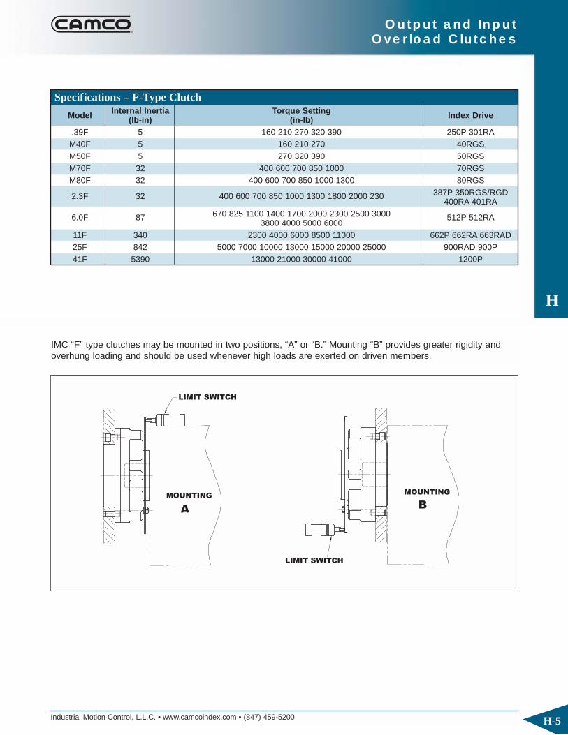
H
Output and Input Overload Clutches
Industrial Motion Control, L.L.C. • www.camcoindex.com • (847) 459-5200 H-5
Specifications – F-Type Clutch
Model Internal Inertia Torque Setting Index Drive(lb-in) (in-lb).39F 5 160 210 270 320 390 250P 301RAM40F 5 160 210 270 40RGSM50F 5 270 320 390 50RGSM70F 32 400 600 700 850 1000 70RGSM80F 32 400 600 700 850 1000 1300 80RGS
2.3F 32 400 600 700 850 1000 1300 1800 2000 230 387P 350RGS/RGD400RA 401RA
6.0F 87 670 825 1100 1400 1700 2000 2300 2500 3000 512P 512RA3800 4000 5000 6000
11F 340 2300 4000 6000 8500 11000 662P 662RA 663RAD25F 842 5000 7000 10000 13000 15000 20000 25000 900RAD 900P41F 5390 13000 21000 30000 41000 1200P
LIMIT SWITCH
LIMIT SWITCH
MOUNTING
A
MOUNTING
B
IMC “F” type clutches may be mounted in two positions, “A” or “B.” Mounting “B” provides greater rigidity andoverhung loading and should be used whenever high loads are exerted on driven members.

Industrial Motion Control, L.L.C. • www.camcoindex.com • (847) 459-5200
H
H-6
Output and Input Overload Clutches
“S” Clutch: Shaft to Flange Mounting
G
E
H
(2x) N
J
A
BD
F
(Lx) K
C
M
IMC “S” type clutches are designed to mount on IMCindex drives without output flanges. The combinationof key and clamped hub design provides a rigid andbacklash-free connection.
* Dimensions in millimeters ** Also 1.2500
† Dimension decreases .06 during overload †† Dimension decreases .09 during overload
††† Dimension decreases .12 during overload †††† Dimension decreases 1.5 mm during overload
Model A B C D E F G H J K L M N.39S 0.6250 3.38 2.63 2.375 0.40 0.187 .66† 2.22 4.75 10-32 4 2.88 0.250
M40S* 16 86 67 60.3 10.6 5 17†††† 56.4 120 M5 4 73 6M50S* 20 86 67 60.3 10.6 6 17†††† 56.4 150 M5 4 73 6M70S* 25 130 84 90 14 8 19†††† 70 165 M8 4 110 8M80S* 30 130 84 90 14 8 19†††† 70 203 M8 4 110 82.3S 1.0000** 5.12 3.31 3.500 0.56 0.250 .75† 2.75 6.50 5/16-24 4 4.25 0.3126.0S 1.6250 6.50 4.28 4.375 0.81 0.375 1.34†† 3.47 8.00 3/8-24 4 5.25 0.37511S 2.0000 8.50 5.00 5.750 0.81 0.500 1.69†† 4.19 10.00 3/8-24 4 6.75 0.50025S 2.5000 10.25 6.25 7.125 1.06 0.625 1.66††† 5.19 12.00 1/2-13 6 8.25 0.62541S 3.0000 15.00 7.56 10.000 1.06 0.750 2.47††† 6.50 17.00 5/8-18 6 11.75 0.750
Dimensions – S-Type Clutch
All dimensions are subject to change. For actual dimensions, please request the current drawing from IMC.

Industrial Motion Control, L.L.C. • www.camcoindex.com • (847) 459-5200
H
H-7
Output and Input Overload Clutches
Specifications – S-Type Clutch
Model Internal Inertia Torque Setting Index Drive(lb-in) (in-lb).39S 5 160 210 270 320 390 250P 301RAM40S 5 160 210 270 40RGSM50S 5 270 320 390 50RGSM70S 31 400 600 700 850 1000 70RGSM80S 31 400 600 700 850 1000 1300 80RGS
2.3S 31 400 600 700 850 1000 387P 350RGS/RGD1300 1800 2000 230 400RA 401RA
6.0S 83 670 825 1100 1400 1700 2000 2300 2500 3000 512P 512RA3800 4000 5000 6000
11S 320 2300 4000 6000 8500 11000 500RGD/RGS662RA 662P
25S 803 5000 7000 10000 13000 700RGS15000 20000 25000
41S 4750 13000 21000 30000 41000 1200P
LIMIT SWITCH
LIMIT SWITCH
MOUNTING
A
MOUNTING
B
IMC “S” type clutches may be mounted two positions, “A” or “B.” Mounting “B” provides greater rigidity and overhung loading and should be used whenever high loads are exerted on driven members.
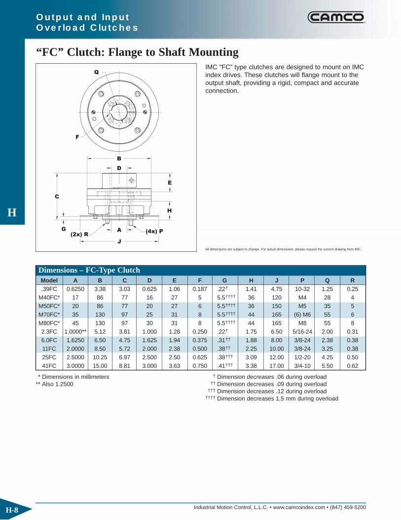
Industrial Motion Control, L.L.C. • www.camcoindex.com • (847) 459-5200
H
H-8
Output and Input Overload Clutches
“FC” Clutch: Flange to Shaft Mounting
(4x) P
E
H
B
(2x) RG
C
J
A
D
Q
F
IMC “FC” type clutches are designed to mount on IMCindex drives. These clutches will flange mount to theoutput shaft, providing a rigid, compact and accurateconnection.
* Dimensions in millimeters ** Also 1.2500
† Dimension decreases .06 during overload †† Dimension decreases .09 during overload
††† Dimension decreases .12 during overload †††† Dimension decreases 1.5 mm during overload
Model A B C D E F G H J P Q R.39FC 0.6250 3.38 3.03 0.625 1.06 0.187 .22† 1.41 4.75 10-32 1.25 0.25
M40FC* 17 86 77 16 27 5 5.5†††† 36 120 M4 28 4M50FC* 20 86 77 20 27 6 5.5†††† 36 150 M5 35 5M70FC* 35 130 97 25 31 8 5.5†††† 44 165 (6) M6 55 6M80FC* 45 130 97 30 31 8 5.5†††† 44 165 M8 55 82.3FC 1.0000** 5.12 3.81 1.000 1.28 0.250 .22† 1.75 6.50 5/16-24 2.00 0.316.0FC 1.6250 6.50 4.75 1.625 1.94 0.375 .31†† 1.88 8.00 3/8-24 2.38 0.3811FC 2.0000 8.50 5.72 2.000 2.38 0.500 .38†† 2.25 10.00 3/8-24 3.25 0.3825FC 2.5000 10.25 6.97 2.500 2.50 0.625 .38††† 3.09 12.00 1/2-20 4.25 0.5041FC 3.0000 15.00 8.81 3.000 3.63 0.750 .41††† 3.38 17.00 3/4-10 5.50 0.62
Dimensions – FC-Type Clutch
All dimensions are subject to change. For actual dimensions, please request the current drawing from IMC.

Industrial Motion Control, L.L.C. • www.camcoindex.com • (847) 459-5200
H
H-9
Output and Input Overload Clutches
Specifications – FC-Type Clutch
Model Internal Inertia Torque Setting Index Drive(lb-in) (in-lb).39FC 7 160 210 270 320 390 250P 301RAM40FC 7 160 210 270 40RGDM50FC 7 270 320 390 50RGDM70FC 43 400 600 700 850 1000 70RGDM80FC 43 400 600 700 850 1000 1300 80RGD
2.3FC 43 400 600 700 850 1000 387P 350RGS/RGD1300 1800 2000 230 400RA 401RA
6.0FC 118 670 825 1100 1400 1700 2000 2300 2500 3000 512P 512RA3800 4000 5000 6000
11FC 456 2300 4000 6000 8500 11000 662P 662RA 663RAD
25FC 1130 5000 7000 10000 13000 900P 900RAD15000 20000 25000
41FC 6940 13000 21000 30000 41000 1200P
LIMIT SWITCH

Industrial Motion Control, L.L.C. • www.camcoindex.com • (847) 459-5200
H
H-10
Output and Input Overload Clutches
“C” Clutch: Shaft to Shaft Mounting
G
C
J
A
D
F
B
H
E
IMC “C” type clutches are designed to mount on IMCindex drives without output flanges. These clutchesare used whenever a positive connection is requiredbetween two shafts.
* Dimensions in millimeters ** Also 1.2500
† Dimension decreases .06 during overload †† Dimension decreases .09 during overload
††† Dimension decreases .12 during overload †††† Dimension decreases 1.5 mm during overload
Model A B C D E F G H J.39C 0.6250 3.38 3.47 0.625 1.06 0.187 .66† 1.84 4.75
M40C* 16 86 88 16 27 5 17†††† 47 120M50C* 20 86 88 20 27 6 17†††† 47 150M70C* 25 130 110 25 31 8 19†††† 58 165M80C* 30 130 110 30 31 8 19†††† 58 2032.3C 1.0000** 5.12 4.34 1.000 1.28 0.250 .75† 2.28 6.506.0C 1.6250 6.50 5.78 1.625 1.94 0.375 1.34†† 2.91 8.0011C 2.0000 8.50 7.00 2.000 2.38 0.500 1.69†† 3.56 10.0025C 2.5000 10.25 8.25 2.500 2.50 0.625 1.66††† 4.38 12.0041C 3.0000 15.00 10.88 3.000 3.63 0.750 2.47††† 5.44 17.00
Dimensions – C-Type Clutch
All dimensions are subject to change. For actual dimensions, please request the current drawing from IMC.

Industrial Motion Control, L.L.C. • www.camcoindex.com • (847) 459-5200
H
H-11
Output and Input Overload Clutches
Specifications – C-Type Clutch
Model Internal Inertia Torque Setting Index Drive(lb-in) (in-lb).39C 7 160 210 270 320 390 250P 301RAM40C 7 160 210 270 40RGSM50C 7 270 320 390 50RGSM70C 44 400 600 700 850 1000 70RGSM80C 44 400 600 700 850 1000 1300 80RGS
2.3C 44 400 600 700 850 1000 387P 350RGS/RGD1300 1800 2000 230 400RA 401RA
6.0C 122 670 825 1100 1400 1700 2000 2300 2500 512P 512RA3000 3800 4000 5000 6000
11C 476 2300 4000 6000 8500 11000 500RGD/RGS 662P
25C 1169 5000 7000 10000 13000 700RGS15000 20000 25000
41C 7225 13000 21000 30000 41000 1200P
LIMIT SWITCH

Industrial Motion Control, L.L.C. • www.camcoindex.com • (847) 459-5200
H
H-12
Output and Input Overload Clutches
“S-SD” Clutch: Shaft to Flange, Shrink-Disk Mounting
G
E
H
(2x) N
J
A
BD (Lx) K
C
M
IMC “S-SD” type clutches are designed to mount onIMC index drives without output flanges. The shrinkdisk design converts clamp loads from multiple highstrength locking screws to radial gripping forcethrough the use of circular wedges, providing the highest capacity mechanical interference connectionavailable.
* Dimensions in millimeters † Dimension decreases .06 during overload †† Dimension decreases .09 during overload
††† Dimension decreases .12 during overload †††† Dimension decreases 1.5 mm during overload
Model A B C D E G H J K L M N.39S-SD 0.6250 3.38 2.62 2.375 0.40 .66† 2.22 4.75 10-32 4 2.88 0.2502.3S-SD 1.0000 5.12 3.31 3.500 0.56 .75† 2.75 6.50 5/16-24 4 4.25 0.3126.0S-SD 1.6250 6.50 3.98 4.375 0.81 1.04†† 3.17 8.00 3/8-24 4 5.25 0.37511S-SD 2.0000 8.50 4.38 5.750 0.82 1.06†† 3.56 10.00 3/8-24 4 6.75 0.50025S-SD 2.5000 10.25 5.75 7.125 1.06 1.16††† 4.69 12.00 1/2-13 6 8.25 0.625
Dimensions – S-SD-Type Clutch
All dimensions are subject to change. For actual dimensions, please request the current drawing from IMC.

Industrial Motion Control, L.L.C. • www.camcoindex.com • (847) 459-5200
H
H-13
Output and Input Overload Clutches
Specifications – S-SD-Type Clutch
Model Internal Inertia Torque Setting Index Drive(lb-in) (in-lb).39S-SD 5 160 210 270 320 390 250P 301RA
2.3S-SD 32 400 600 700 850 1000 387P 350RGS/RGD1300 1800 2000 230 400RA 401RA
6.0S-SD 87 670 825 1100 1400 1700 2000 2300 2500 3000 512P 512RA3800 4000 5000 6000
11S-SD 340 2300 4000 6000 8500 11000 500RGD/RGS 662P25S-SD 842 5000 7000 10000 13000 15000 20000 25000 700RGS 900P
LIMIT SWITCH
LIMIT SWITCH
MOUNTING
A
MOUNTING
B
IMC ‘S-SD’ type clutches may be mounted in two positions, “A” or “B.” Mounting “B” provides greater rigidity and overhung loading and should be used whenever high loads are exerted on driven members.

Industrial Motion Control, L.L.C. • www.camcoindex.com • (847) 459-5200
H
H-14
Output and Input Overload Clutches
“FC-SD” Clutch: Flange to Shaft, Shrink-Disk Mounting
(4x) P
E
H
B
(2x) FG
C
J
A
D
QIMC “FC-SD” type clutches are designed to mount on IMC index drives with output flanges. The shrinkdisk design converts clamp loads from multiple highstrength locking screws to radial gripping forcethrough the use of circular wedges, providing the highest capacity mechanical interference connectionavailable.
* Dimensions in millimeters † Dimension decreases .06 during overload †† Dimension decreases .09 during overload
††† Dimension decreases .12 during overload †††† Dimension decreases 1.5 mm during overload
Model A B C D E F G H J P Q.39FC-SD 0.6250 3.38 3.00 0.625 1.03 0.25 .22† 1.41 4.75 10-32 1.252.3FC-SD 1.0000 5.12 3.81 1.000 1.27 0.31 .22† 1.75 6.50 5/16-24 2.006.0FC-SD 1.6250 6.50 4.46 1.625 1.64 0.38 .31†† 1.88 8.00 3/8-24 2.3811FC-SD 2.0000 8.50 5.06 2.000 1.75 0.38 .38†† 2.25 10.00 3/8-24 3.2525FC-SD 2.5000 10.25 6.50 2.500 2.00 0.50 .38††† 3.09 12.00 1/2-20 4.25
Dimensions – FC-SD-Type Clutch
All dimensions are subject to change. For actual dimensions, please request the current drawing from IMC.

Industrial Motion Control, L.L.C. • www.camcoindex.com • (847) 459-5200
H
H-15
Output and Input Overload Clutches
Specifications – FC-SD-Type Clutch
Model Internal Inertia Torque Setting Index Drive(lb-in) (in-lb).39FC-SD 7 160 210 270 320 390 250P 301RA
2.3FC-SD 43 400 600 700 850 1000 387P 350RGS/RGD1300 1800 2000 230 400RA 401RA
6.0FC-SD 118 670 825 1100 1400 1700 2000 2300 2500 3000 512P 512RA3800 4000 5000 6000
11FC-SD 456 2300 4000 6000 8500 11000 500RGD/RGS 662P662RA
25FC-SD 1130 5000 7000 10000 13000 700RGS 900P 900RAD15000 20000 25000
LIMIT SWITCH

Industrial Motion Control, L.L.C. • www.camcoindex.com • (847) 459-5200
H
H-16
Output and Input Overload Clutches
“C-SD” Clutch: Shaft to Shaft, Shrink-Disk Mounting
G
C
J
A
D
B
H
E
IMC “C-SD” type clutches are designed to mount onIMC index drives without output flanges. The shrinkdisk design converts clamp loads from multiple highstrength locking screws to radial gripping forcethrough the use of circular wedges, providing the highest capacity mechanical interference connectionavailable.
* Dimensions in millimeters † Dimension decreases .06 during overload †† Dimension decreases .09 during overload
††† Dimension decreases .12 during overload †††† Dimension decreases 1.5 mm during overload
Model A B C D E G H J.39C-SD 0.6250 3.38 3.44 0.625 1.03 .66† 1.84 4.752.3C-SD 1.0000 5.12 4.34 1.000 1.28 .75† 2.28 6.506.0C-SD 1.6250 6.50 5.19 1.625 1.64 1.04†† 2.61 8.0011C-SD 2.0000 8.50 5.75 2.000 1.75 1.06†† 2.93 10.0025C-SD 2.5000 10.25 7.31 2.500 2.00 1.16††† 3.88 12.00
Dimensions – C-SD-Type Clutch
All dimensions are subject to change. For actual dimensions, please request the current drawing from IMC.

Industrial Motion Control, L.L.C. • www.camcoindex.com • (847) 459-5200
H
H-17
Output and Input Overload Clutches
Specifications – C-SD-Type Clutch
Model Internal Inertia Torque Setting Index Drive(lb-in) (in-lb).39C-SD 7 160 210 270 320 390 250P 301RA
2.3C-SD 44 400 600 700 850 1000 387P 350RGS/RGD1300 1800 2000 230 400RA 401RA
6.0C-SD 122 670 825 1100 1400 1700 2000 2300 2500 3000 512P 512RA3800 4000 5000 6000
11C-SD 476 2300 4000 6000 8500 11000 500RGD/RGS 662P662RA
25C-SD 1169 5000 7000 10000 13000 700RGS 900P 900RAD15000 20000 25000
LIMIT SWITCH

Industrial Motion Control, L.L.C. • www.camcoindex.com • (847) 459-5200
H
H-18
Output and Input Overload Clutches
RITE-TORQ® “S/S” Clutch: Shaft to Shaft Mounting
D
C
B
D
A
E
G
H
F TRIP TRAVEL
J
(2x) NFOR SPANNERWRENCH
IMC “S/S” type clutches are designed to mount on IMC index drives without output flanges. The combination of key and clamped hub design providesa rigid and backlash-free connection.
Model A B C D E F G H J NRT3-S/S 3.46 3.75 3.37 1.75 1.00 0.06 1.86 1.00 .4375 - .7500 0.25RT5-S/S 4.34 5.50 5.12 2.75 1.19 0.08 2.31 1.22 .6250 - 1.2500 0.31RT6-S/S 6.68 7.00 6.50 3.75 1.84 0.09 3.19 2.06 1.0000 - 2.0000 0.31RT8-S/S 7.00 9.00 8.50 5.00 2.06 0.11 3.50 2.00 1.5000 - 2.5000 0.31
Specifications – RITE-TORQ® S/S Clutch
Model Internal Inertia Adjustable Torque Setting Ranges Index Drive(lb-in) (in-lb)RT3-S/S 9 100-175, 175-275, 250-350, 325-500 P325RT5-S/S 54 500-850, 800-1700, 1600-3000 P400RT6-S/S 170 1000-2700, 2500-5000, 4000-8500 P500RT8-S/S 650 4000-9500, 6000-15,500
Dimensions – RITE-TORQ® S/S Clutch
All dimensions are subject to change. For actual dimensions, please request the current drawing from IMC.

Industrial Motion Control, L.L.C. • www.camcoindex.com • (847) 459-5200
H
H-19
Output and Input Overload Clutches
All dimensions are subject to change. For actual dimensions, please request the current drawing from IMC.
RITE-TORQ® “F/F” Clutch: Flange to Flange Mounting
(4x) K1
(2x) K2
H
C
L
45°
FOR SPANNERWRENCH
(2x) N
F TRIP TRAVEL
B
JG
MA
E
D
IMC “F/F” type clutches are designed to mount on IMCindex drives. These clutches will flange mount to theoutput shaft, providing a rigid, compact, and accurateconnection with the driven member.
Specifications – RITE-TORQ® F/F Clutch
Model Internal Inertia Adjustable Torque Setting Ranges Index Drive(lb-in) (in-lb)RT3-F/F 7 100-175, 175-275, 250-350, 325-500 FD-100RT5-F/F 42 500-850, 800-1700, 1600-3000 FD-162RT6-F/F 118 1000-2700, 2500-5000, 4000-8500 FD-250 FD-300RT8-F/F 453 4000-9500, 6000-15,500
All dimensions are subject to change. For actual dimensions, please request the current drawing from IMC.
Model K1 K2 L M NRT3-F/F 10-32 X 1/4 DP 1/4 Dowel X 1/4 DP 2.88 1.20 0.25RT5-F/F 5/16-18 X 5/16 DP 5/16 Dowel X 5/16 4.25 1.56 0.31RT6-F/F 3/8-16 X 5/8 DP 3/8 Dowel X 5/8 DP 5.50 2.19 0.31RT8-F/F 1/2-13 X 3/4 DP 1/2 Dowel X 3/4 DP 7.25 2.41 0.39
Model A B C D E F G H JRT3-F/F 2.19 3.75 3.37 2.12 0.58 0.06 0.25 2.373/2.372 .788/.787RT5-F/F 2.78 5.50 5.13 3.12 0.66 0.08 0.38 3.498/3.497 1.501/1.50RT6-F/F 3.75 7.00 6.50 4.12 0.69 0.09 0.38 4.623/4.622 2.501/2.500RT8-F/F 4.09 9.00 8.50 5.62 0.88 0.11 0.38 6.248/6.247 3.001/3.000
Dimensions – RITE-TORQ® F/F Clutch

Industrial Motion Control, L.L.C. • www.camcoindex.com • (847) 459-5200
H
H-20
Output and Input Overload Clutches
RITE-TORQ® “F/S” Clutch: Flange to Shaft Mounting
J
(2x) NFOR SPANNERWRENCH
D
C
B
A
E
B
F TRIP TRAVEL
LGK
IMC “F/S” type clutches are designed to mount onIMC index drives. These clutches will flange mount to the output shaft, providing a rigid, compact andaccurate connection.
Specifications – RITE-TORQ® F/S Clutch
Model Internal Inertia Adjustable Torque Setting Ranges Index Drive(lb-in) (in-lb)RT3-F/S 9 100-175, 175-275, 250-350, 325-500 FD-100RT5-F/S 54 500-850, 800-1700, 1600-3000 FD-162RT6-F/S 170 1000-2700, 2500-5000, 4000-8500 FD-250 FD-300RT8-F/S 630 4000-9500, 6000-15,500
All dimensions are subject to change. For actual dimensions, please request the current drawing from IMC.
Model A B C D E F G H J K L NRT3-F/S 3.03 3.75 3.37 1.75 0.58 0.06 0.25 1.00 .4375-.7500 2.12 .788/.787 0.25RT5-F/S 3.81 5.50 5.13 2.75 0.66 0.08 0.38 1.22 .6250-1.2500 3.12 1.501/1.500 0.31RT6-F/S 5.56 7.00 6.50 3.75 0.69 0.09 0.38 2.06 1.0000-2.0000 4.12 2.501/2.500 0.31RT8-F/S 5.81 9.00 8.50 5.00 0.88 0.11 38.00 2.00 1.5000-2.5000 5.62 3.001/3.000 0.39
Dimensions – RITE-TORQ® F/S Clutch

Industrial Motion Control, L.L.C. • www.camcoindex.com • (847) 459-5200
H
H-21
Output and Input Overload Clutches
RITE-TORQ® “S/F” Clutch: Shaft to Flange Mounting
J
(2x) N
WRENCH
FOR SPANNER
(4x) K1
(2x) K2
TRAVELF TRIP
D
B
G
E
H
C
AM
L
45°
IMC “S/F” type clutches are designed to mount onIMC index drives. These clutches will shaft mount tothe indexer output, providing a rigid, compact andaccurate connection.
Specifications – RITE-TORQ® S/F Clutch
Model Internal Inertia Adjustable Torque Setting Ranges Index Drive(lb-in) (in-lb)RT3-S/F 8 100-175, 175-275, 250-350, 325-500 P325RT5-S/F 43 500-850, 800-1700, 1600-3000 P400RT6-S/F 125 1000-2700, 2500-5000, 4000-8500 P500RT8-S/F 460 4000-9500, 6000-15,500
All dimensions are subject to change. For actual dimensions, please request the current drawing from IMC.
Model K1 K2 L M NRT3-S/F 10-32 X 1/4 DP 1/4 Dowel X 1/4 DP 2.88 1.20 0.25RT5-S/F 3/16-18 X 5/16 DP 5/16 Dowel X 5/16 4.25 1.56 0.31RT6-S/F 3/8-16 X 5/8 DP 3/8 Dowel X 5/8 DP 5.50 2.19 0.31RT8-S/F 1/2-13 X 3/4 DP 1/2 Dowel X 3/4 DP 7.25 2.41 0.39
Model A B C D E F G H JRT3-S/F 2.63 3.75 3.37 1.75 1.00 0.06 1.86 2.373/2.372 .4375-.7500RT5-S/F 3.31 5.50 5.13 2.75 1.19 0.08 2.31 3.498/3.497 .6250-1.2500RT6-S/F 4.87 7.00 6.50 3.75 1.84 0.09 3.19 4.623/4.622 1.0000-2.0000RT8-S/F 5.28 9.00 8.50 5.00 2.06 0.11 3.50 6.248/6.247 1.5000-2.5000
Dimensions – RITE-TORQ® S/F Clutch

Industrial Motion Control, L.L.C. • www.camcoindex.com • (847) 459-5200
H
H-22
Input Flange Mounting Specifications
45°
RT3
22.5°
RT5 RT6 & RT8
(1x) A
(4x) B
(2x) C D
30° (3x) C
(3x) B
(2x) AD
45° (4x) C
(4x) B
(2x) A
D
Output and Input Overload Clutches
Model A B C D
RT3 .2362/.2358 dia. x 50 dp Drilled & Counter Bored for 1/4-20 x .50 dp 1.3781/4 Socket Head Cap Screw
RT5 .3750/.3745 dia. x .75 dp 3/8-16 x .75 dp Drilled & Counter Bored for 2.2503/8 Socket Head Cap Screw
RT6 .3750/.3745 dia. x .75 dp 3/8-16 x .75 dp Drilled & Counter Bored for 3.2503/8 Socket Head Cap Screw
RT8 .5000/.4995 dia. x 1.00 dp 1/2-13 x 1.00 dp Drilled & Counter Bored for 4.2501/2 Socket Head Cap Screw

Industrial Motion Control, L.L.C. • www.camcoindex.com • (847) 459-5200
H
H-23
Output and Input Overload Clutches
Input Overload Clutches (IOC)
F
400 I0C - 1000 IOC K
300-IOC 1.250-1.938
3.500
3.500
2.938-3.5
1.938-2.938
1.938
1.438-1.938
600-IOC
800-IOC
700-IOC
500-IOC
400-IOC
350-IOC
MODEL
.938-1.188
1.125-1.250
0.938
.625-.875
.625-.748
225-IOC
260-IOC
250-IOC
200-IOC
180-IOC
A
2.944.190.25--------2.1886.816.00
--------
--------
--------
--------
--------
--------
9.3810.00
12.12
16.37
12.25
13.75
8.00
10.00
6.00
7.88
9.38
6.81
3.938
3.938
4.438
2.438
3.188
2.438
5.53
6.44
6.44
4.19
8.5
9.95
0.25
0.25
0.25
0.25
0.25
0.25
5.12
6.25
7.50
3.63
5.12
2.94
--------
0.750
D2
--------
1.188
--------
D1CB
5.004.00
4.00
4.00
5.00
5.00
3.50
3.50
4.35
4.35
1.188
1.688
--------
1.000
--------
GFE
2.43
2.43
2.94
2.94
2.940.25
0.25
0.25
--------
--------
1.88
1.88
1.88
1.75
1.75
C
180 IOC - 350 I0C
J H G
L
60.81 2.6875.004.50 5.65 0.344
0.81
0.81
0.81
0.81
0.81
0.81
10.25
7.507.00
8.75
9.75
9.25
5.25
7.00
4.50
5.75
7.50
5.00
8.03
11.95
10.50
8.03
6.75
5.65
4.688
5.750
5.500
4.000
3.250
3.000
6 0.531
6
6
0.656
0.781
6
6
6
0.531
0.531
0.344
0.81
0.81
L
0.81
0.81
0.81
J K
3.753.25
3.25
3.25
3.75
3.75
3.00
3.00
3.50
3.50
4.06
4.06
4.06
3.35
3.35
H
E
NM P
1.562
2.000
2.125
1.437
1.062
6 0.281
4
4
0.343
0.281
4
4
0.281
0.219
0°3 0.281
3 0.469
3
4
0.594
0.719
2
3
3
0.169
0.469
0.281
0°
0°
0°
0°
0°
0°
SQ R
0.2194
3
3
0.281
0.219
3
3
0.219
0.156
30°
45°
35°
35°
45°
D2 D1
(Qx) R
B
S
A
(Nx) P
M
AD
JU
ST
ING
TO
OL
(BORE RANGE)
IMC’s Input Overload Clutches (IOC) are used when an output overloadclutch cannot be mounted to your index drive. The trip torque setting ofthe Input Overload Clutches is set under fully loaded, field conditions.When an overload condition is removed, the clutch automatically takeshold and carries peak load as usual. Resetting is required only when theload changes. Since the clutch mounts to the gear reducer, the IOC isselected based on the size of the gear reducer used in the application.Your IMC sales representative will help determine the proper clutch andclutch bore size.
IOC Model Reducer180-IOC R180225-IOC R225260-IOC R260300-IOC 7300C350-IOC 7350C400-IOC 7400C500-IOC 7500C600-IOC 7600C700-IOC 7700C800-IOC 7800C

Industrial Motion Control, L.L.C. • www.camcoindex.com • (847) 459-5200
H
H-24
Output and Input Overload Clutches
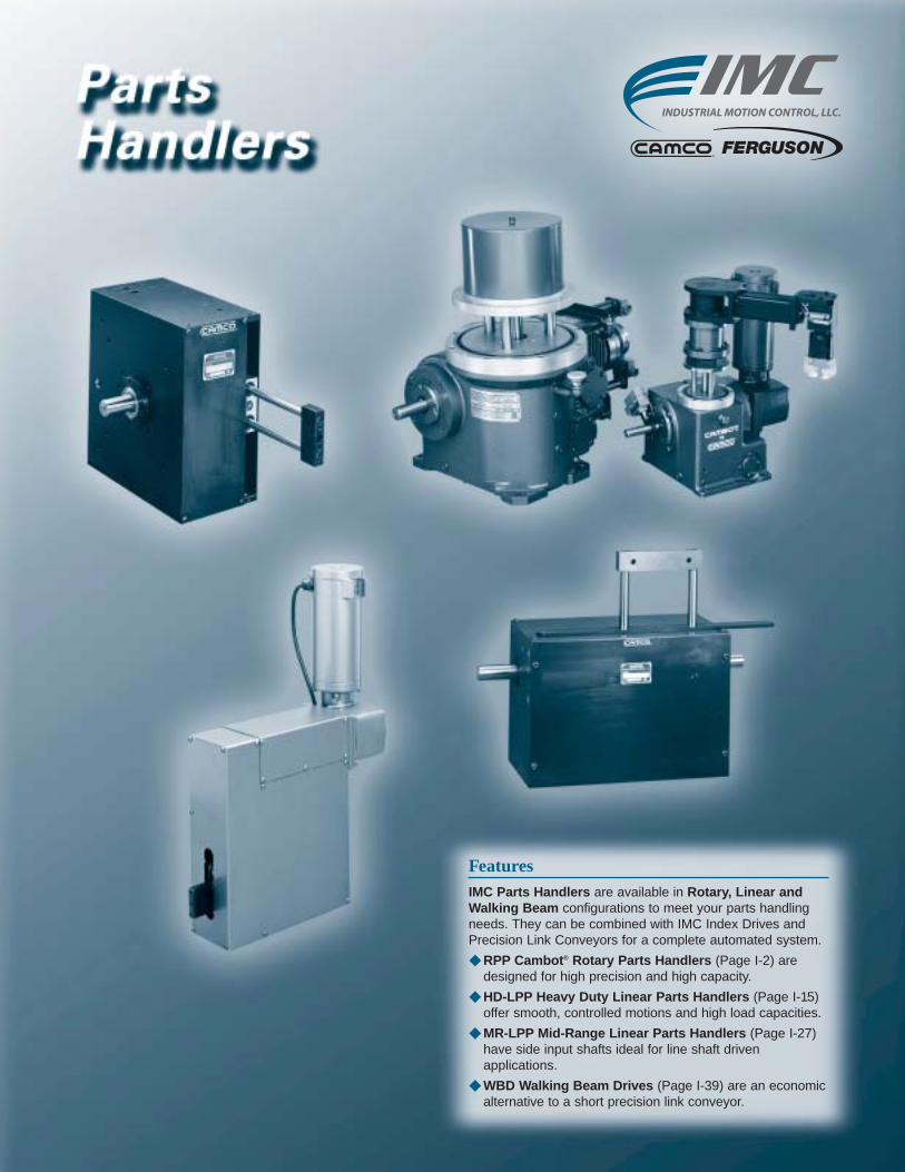
FeaturesIMC Parts Handlers are available in Rotary, Linear andWalking Beam configurations to meet your parts handlingneeds. They can be combined with IMC Index Drives andPrecision Link Conveyors for a complete automated system.
◆ RPP Cambot® Rotary Parts Handlers (Page I-2) aredesigned for high precision and high capacity.
◆ HD-LPP Heavy Duty Linear Parts Handlers (Page I-15)offer smooth, controlled motions and high load capacities.
◆ MR-LPP Mid-Range Linear Parts Handlers (Page I-27)have side input shafts ideal for line shaft driven applications.
◆ WBD Walking Beam Drives (Page I-39) are an economicalternative to a short precision link conveyor.

Industrial Motion Control, L.L.C. • www.camcoindex.com • (847) 459-5200
I
I-2
RPP Cambot® Parts Handlers
The IMC RPP Cambot® Rotary Parts Handler isdesigned for high precision and high capacity. This proven design can be used in a wide variety of industries including automotive, packaging andelectronics among others. The RPP can be combinedwith other IMC products such as index drives and precision conveyors for a complete, automated system. The RPP is ideal for pick and place appli-cations with features including:
◆ Rugged and precise cam operated mechanismsengineered for a minimum of 8000 hours of maintenance-free life.
◆ Hardened and ground cams drive both the lift androtary axes.
◆ Preloaded precision cam followers eliminate backlash and ensure smooth movement.
◆ Preloaded taper roller bearings on the camshaft(Input Shaft).
◆ Four-point contact preloaded roller bearing on therotary axis.
◆ All bearings are lubricated by an oil bath.
◆ One-piece lift arm.
◆ Ball bushings (recirculating-ball type) support themain lift shaft and turn the large output surface andride on hardened shafts for stability and stiffness.
◆ Manufactured in a fully integrated application,design, manufacturing and inspection environment.
The RPP Cambot® can be made with custom motionsequences to synchronize with specific applicationrequirements. An IMC Engineer can quickly evaluatepossible sequences using IMC’s sizing software.
Cambot® RPP Rotary Parts Handlers

Industrial Motion Control, L.L.C. • www.camcoindex.com • (847) 459-5200
I
I-3
RPP Cambot® Parts Handlers
Steel “Top Hat” toProtect Guide Shafts
Multiple Guide Shaftsfor Stable Output
Oil Lubrication
Arm or DialMounting Surface
Hardened &Ground Cams
PreloadedBearings
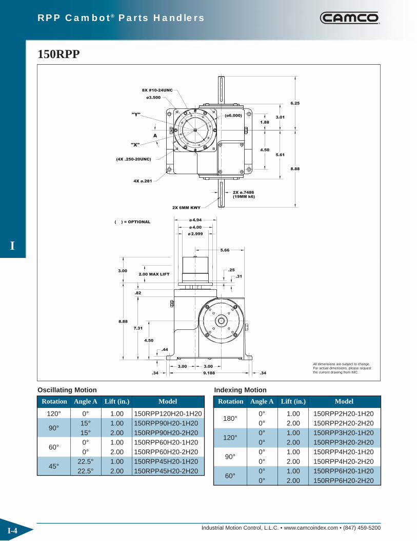
RPP Cambot® Parts Handlers
4.00ø
8.88
.34
7.31
.44
4.50
2.00 MAX LIFT
.82
9.188
3.00 3.00
.34
.25
2.999ø
5.66
.31
4X ø.281
( ) = OPTIONAL
(4X .250-20UNC)
"X"
A
8X #10-24UNC
"Y"
ø3.500
4.94
2X 6MM KWY
ø
(19MM k6)ø.74862X
5.61
4.50
ø6.000)(
1.88
3.01
8.88
6.25
3.00
150RPP
Industrial Motion Control, L.L.C. • www.camcoindex.com • (847) 459-5200
I
I-4
All dimensions are subject to change. For actual dimensions, please request the current drawing from IMC.
Rotation Angle A Lift (in.) Model
120° 0° 1.00 150RPP120H20-1H20
90°15° 1.00 150RPP90H20-1H2015° 2.00 150RPP90H20-2H20
60°0° 1.00 150RPP60H20-1H200° 2.00 150RPP60H20-2H20
45°22.5° 1.00 150RPP45H20-1H2022.5° 2.00 150RPP45H20-2H20
Rotation Angle A Lift (in.) Model
180°0° 1.00 150RPP2H20-1H200° 2.00 150RPP2H20-2H20
120°0° 1.00 150RPP3H20-1H200° 2.00 150RPP3H20-2H20
90°0° 1.00 150RPP4H20-1H200° 2.00 150RPP4H20-2H20
60°0° 1.00 150RPP6H20-1H200° 2.00 150RPP6H20-2H20
Oscillating Motion Indexing Motion
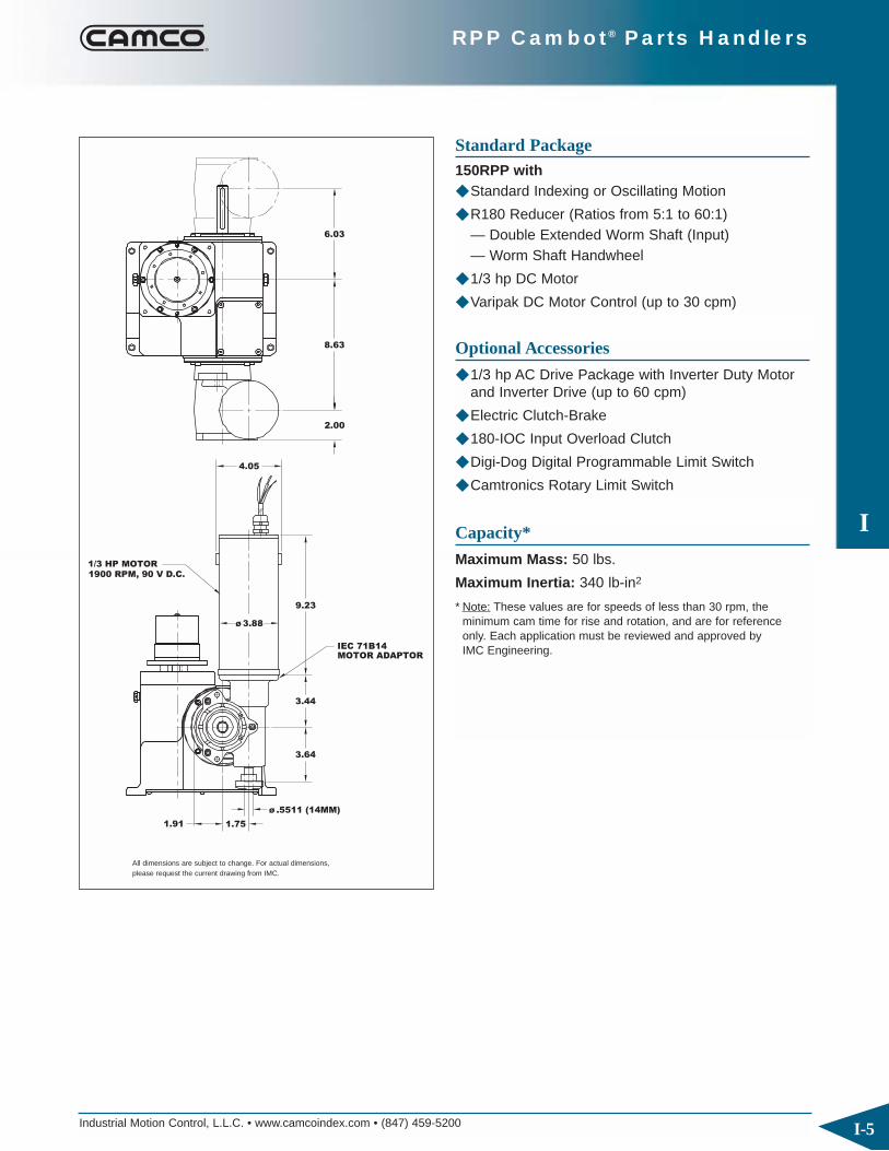
I
RPP Cambot® Parts Handlers
Industrial Motion Control, L.L.C. • www.camcoindex.com • (847) 459-5200 I-5
1.91
1900 RPM, 90 V D.C.1/3 HP MOTOR
1.75
ø .5511 (14MM)
3.64
MOTOR ADAPTORIEC 71B14
9.23
ø 3.88
3.44
4.05
2.00
8.63
6.03
All dimensions are subject to change. For actual dimensions, please request the current drawing from IMC.
Standard Package150RPP with◆ Standard Indexing or Oscillating Motion
◆ R180 Reducer (Ratios from 5:1 to 60:1)— Double Extended Worm Shaft (Input)— Worm Shaft Handwheel
◆ 1/3 hp DC Motor
◆ Varipak DC Motor Control (up to 30 cpm)
Optional Accessories
◆ 1/3 hp AC Drive Package with Inverter Duty Motor and Inverter Drive (up to 60 cpm)
◆ Electric Clutch-Brake
◆ 180-IOC Input Overload Clutch
◆ Digi-Dog Digital Programmable Limit Switch
◆ Camtronics Rotary Limit Switch
Capacity*
Maximum Mass: 50 lbs.
Maximum Inertia: 340 lb-in2
* Note: These values are for speeds of less than 30 rpm, the minimum cam time for rise and rotation, and are for reference only. Each application must be reviewed and approved by IMC Engineering.

Industrial Motion Control, L.L.C. • www.camcoindex.com • (847) 459-5200
I
I-6
RPP Cambot® Parts Handlers
8X .250-20UNC
2X .250 KWY
2.88
2.88
6.53
4.38
.40
8.28
10.03
A
X
Y
ø7.875
2X ø 1.1875
2.88 3.750
9.12.75 .50
.69
6.12
10.50
12.38
4.123.00 MAX LIFT
.75
.38
ø 3.72
ø 6.62
ø 6.999
ø 8.75
4X ø.406
300RPP
All dimensions are subject to change. For actual dimensions, please request the current drawing from IMC.
Rotation Angle A Lift (in.) Model
120° 0°1.00 300RPP120H24-1H242.00 300RPP120H24-2H241.00 300RPP90H24-1H24
90° 15° 2.00 300RPP90H24-2H243.00 300RPP90H24-3H241.00 300RPP60H24-1H24
60° 0° 2.00 300RPP60H24-2H243.00 300RPP60H24-3H241.00 300RPP45H24-1H24
45° 22.5° 2.00 300RPP45H24-2H243.00 300RPP45H24-3H24
Rotation Angle A Lift (in.) Model
1.00 300RPP2H24-1H24180° 0° 2.00 300RPP2H24-2H24
3.00 300RPP2H24-3H241.00 300RPP3H24-1H24
120° 0° 2.00 300RPP3H24-2H243.00 300RPP3H24-3H241.00 300RPP4H24-1H24
90° 0° 2.00 300RPP4H24-2H243.00 300RPP4H24-3H241.00 300RPP6H24-1H24
60° 0° 2.00 300RPP6H24-2H243.00 300RPP6H24-3H24
Oscillating Motion Indexing Motion
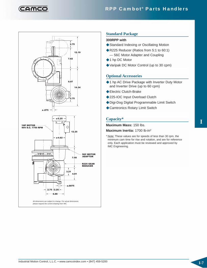
Industrial Motion Control, L.L.C. • www.camcoindex.com • (847) 459-5200
I
I-7
RPP Cambot® Parts Handlers
6.88
2.75
90V D.C. 1750 RPM1HP MOTOR
REDUCER
ø.6875
3.21
2.25
4.81
7.50
ø 4.62
ø 5.25
12.25
R225 GEAR
56C MOTORADAPTOR
ø .875
14.34
9.97
12.19
7.82
2.75
2.75
All dimensions are subject to change. For actual dimensions, please request the current drawing from IMC.
Standard Package
300RPP with◆ Standard Indexing or Oscillating Motion
◆ R225 Reducer (Ratios from 5:1 to 60:1)— 56C Motor Adapter and Coupling
◆ 1 hp DC Motor
◆ Varipak DC Motor Control (up to 30 cpm)
Optional Accessories
◆ 1 hp AC Drive Package with Inverter Duty Motor and Inverter Drive (up to 60 cpm)
◆ Electric Clutch-Brake
◆ 225-IOC Input Overload Clutch
◆ Digi-Dog Digital Programmable Limit Switch
◆ Camtronics Rotary Limit Switch
Capacity*
Maximum Mass: 150 lbs.
Maximum Inertia: 1700 lb-in2
* Note: These values are for speeds of less than 30 rpm, the minimum cam time for rise and rotation, and are for reference only. Each application must be reviewed and approved by IMC Engineering.

Industrial Motion Control, L.L.C. • www.camcoindex.com • (847) 459-5200
I
I-8
RPP Cambot® Parts Handlers
10.53
12.16
ø10.75
.88
7.38
6.34
14.3812.84
MAX LIFT4.00
12.88
5.003.88
.63
ø 8.749
.46
.79
4X .531
A
X
8X .312-18UNC
ø9.750
Y3.94
ø12.25
2X .250 KWY
2X ø 1.1875
3.94
8.16
ø 3.72
6.12
.40
500RPP
All dimensions are subject to change. For actual dimensions, please request the current drawing from IMC.
Rotation Angle A Lift (in.) Model
120° 0°2.00 500RPP120H32-2H323.00 500RPP120H32-3H322.00 500RPP90H32-2H32
90° 15° 3.00 500RPP90H32-3H324.00 500RPP90H32-4H322.00 500RPP60H32-2H32
60° 0° 3.00 500RPP60H32-3H324.00 500RPP60H32-4H322.00 500RPP45H32-2H32
45° 22.5° 3.00 500RPP45H32-3H324.00 500RPP45H32-4H32
Rotation Angle A Lift (in.) Model
2.00 500RPP2H32-2H32180° 0° 3.00 500RPP2H32-3H32
4.00 500RPP2H32-4H322.00 500RPP3H32-2H32
120° 0° 3.00 500RPP3H32-3H324.00 500RPP3H32-4H322.00 500RPP4H32-2H32
90° 0° 3.00 500RPP4H32-3H324.00 500RPP4H32-4H322.00 500RPP6H32-2H32
60° 0° 3.00 500RPP6H32-3H324.00 500RPP6H32-4H32
Oscillating Motion Indexing Motion

Industrial Motion Control, L.L.C. • www.camcoindex.com • (847) 459-5200
I
I-9
RPP Cambot® Parts Handlers
2.252.75
6.88
ø.6875
3.214.81
ADAPTOR56C MOTOR
R225 GEARREDUCER
7.50
1HP MOTOR90V D.C. 1750 RPM
ø 4.62
ø .875
ø 5.25
12.25
2.75
15.97
11.60
13.94
9.56
2.75
All dimensions are subject to change. For actual dimensions, please request the current drawing from IMC.
Standard Package
500RPP with◆ Standard Indexing or Oscillating Motion
◆ R225 Reducer (Ratios from 5:1 to 60:1)— 56C Motor Adapter and Coupling
◆ 1 hp DC Motor
◆ Varipak DC Motor Control (up to 30 cpm)
Optional Accessories
◆ 1 hp AC Drive Package with Inverter Duty Motor and Inverter Drive (up to 60 cpm)
◆ R260 Reducer (Ratios from 5:1 to 60:1)
◆ Electric Clutch-Brake
◆ 225-IOC Input Overload Clutch
◆ Digi-Dog Digital Programmable Limit Switch
◆ Camtronics Rotary Limit Switch
Capacity*
Maximum Mass: 180 lbs.
Maximum Inertia: 3415 lb-in2
* Note: These values are for speeds of less than 30 rpm, the minimum cam time for rise and rotation, and are for reference only. Each application must be reviewed and approved by IMC Engineering.

Industrial Motion Control, L.L.C. • www.camcoindex.com • (847) 459-5200
I
I-10
RPP Cambot® Parts Handlers
4.94
4.94
.75
21.0023.00
8.005.50
.75 20.25
12.50
4X ø.656
MAX LIFT
7.88
X
6.00
ø 10.50
ø 13.00
ø 11.00
.38
ø13.25
.75
A
2X .500 KWY
2X ø1.9375
18.38
13.38
8X .375-16UNC
Y
ø12.000
ø 6.00
12.84
7.25
.59
900RPP
All dimensions are subject to change. For actual dimensions, please request the current drawing from IMC.
Rotation Angle A Lift (in.) Model
120° 0°2.00 900RPP120H48-2H484.00 900RPP120H48-4H482.00 900RPP90H48-2H48
90° 15° 4.00 900RPP90H48-4H486.00 900RPP90H48-6H482.00 900RPP60H48-2H48
60° 0° 4.00 900RPP60H48-4H486.00 900RPP60H48-6H482.00 900RPP45H48-2H48
45° 22.5° 4.00 900RPP45H48-4H486.00 900RPP45H48-6H48
Rotation Angle A Lift (in.) Model
2.00 900RPP2H48-2H48180° 0° 4.00 900RPP2H48-4H48
6.00 900RPP2H48-6H482.00 900RPP3H48-2H48
120° 0° 4.00 900RPP3H48-4H486.00 900RPP3H48-6H482.00 900RPP4H48-2H48
90° 0° 4.00 900RPP4H48-4H486.00 900RPP4H48-6H482.00 900RPP6H48-2H48
60° 0° 4.00 900RPP6H48-4H486.00 900RPP6H48-6H48
Oscillating Motion Indexing Motion

Industrial Motion Control, L.L.C. • www.camcoindex.com • (847) 459-5200
I
I-11
RPP Cambot® Parts Handlers
1.00ø1.9375
5.25
180V D.C. 1750 RPM2HP MOTOR
REDUCER
ø 1.1875
3.50 3.95
5.207.75
16.30
10.56
ø 6.62
ø 6.97
73500C GEAR
ADAPTOR145TC MOTOR
7.25
4.62
18.75
13.38
4.62
12.62
1.00
All dimensions are subject to change. For actual dimensions, please request the current drawing from IMC.
Standard Package
900RPP with◆ Standard Indexing or Oscillating Motion
◆ 7350C Reducer (Ratios from 5:1 to 60:1)— 143TC Motor Adapter and Coupling
◆ 2 hp DC Motor
◆ Varipak DC Motor Control (up to 30 cpm)
Optional Accessories
◆ 2 hp AC Drive Package with Inverter Duty Motor and Inverter Drive (up to 60 cpm)
◆ Electric Clutch-Brake
◆ 350-IOC Input Overload Clutch
◆ Digi-Dog Digital Programmable Limit Switch
◆ Camtronics Rotary Limit Switch
Capacity*
Maximum Mass: 500 lbs.
Maximum Inertia: 27,300 lb-in2
* Note: These values are for speeds of less than 30 rpm, the minimum cam time for rise and rotation, and are for reference only. Each application must be reviewed and approved by IMC Engineering.

Industrial Motion Control, L.L.C. • www.camcoindex.com • (847) 459-5200
I
I-12
RPP Cambot® Parts Handlers
Y
X
Input Rotation (deg)
Input Rotation (deg)
Ro
tati
on
(deg)
0.00
R
180 360
Lif
t (i
n.)
0.00
H
90 180 270 360
R
Y
X
0°
UP
DOWN
Up
Down
90 270
H
START
START
Timing Diagram – Oscillator
Motion Options◆ Standard starting position (home) at time 0 is at
maximum rise (up) and at the X rotary position.
◆ The standard sequence can be mirrored in eitherthe lift, rotary or both:
— The mirrored lift starts in the zero elevation or down position
— The mirrored rotary motion starts at Y.
◆ Custom motion times are also available – consultyour Sales Agent for more information.

Industrial Motion Control, L.L.C. • www.camcoindex.com • (847) 459-5200
I
I-13
RPP Cambot® Parts Handlers
R
0
0°
0.0
Lif
t (i
n.)
H
36090 180 270
R
Index R
ota
tion (
deg)
0.00
Input Rotation (deg)
90 180 270 360
START
DOWN
UPH
0°
START
UP
DOWN
R
Timing Diagram – Indexer
Motion Options◆ Standard starting position (home) at time 0 is at
maximum rise (up) and at the start of a counter-clockwise index (right-hand cam helix).
◆ The standard sequence can be mirrored in eitherthe lift, rotary or both:
— The mirrored lift starts in the zero elevation or down position
— The mirrored rotary motion is a clockwise index (left-hand helix)
◆ Custom motion times are also available – consultyour Sales Agent for more information.

Industrial Motion Control, L.L.C. • www.camcoindex.com • (847) 459-5200
I
I-14
RPP Cambot® Parts Handlers
1. Model
2. Rotary Motion (degrees)
◆ Oscillator or indexer
◆ Oscillator: Home at X or Y
◆ Indexer: CW or CCW index
RPP Ordering Procedure3. Lift (inches)
4. Input Shaft: Side 1, Side 2 or Double Input (DI)
5. Mounting Position: 1-6
1. Reducer Model, Ratio and Mounting Position
2. Motor Adaptor Model
3. Motor size
Reducer Ordering Procedure
12
36
45
1 2 3
Start/home Position
Input
Standard Output Sequence
Position of Shafts Indexer Mounting Position
AE: Input Shaft AS: Output Shaft
5
3
1
6
4
2AS:
AS:
AS:
AS: AS:
AS:
AE:
AE:AE:
AE: AE:
AE:
Oscillator
"X"
"X"
"Y"
"Y"
Indexer
Angle
Output
DI
(Standard)
(Standard)
1
CCW CW
B-1-RH B-1-LHA-1-RH A-1-LH D-1-RH D-1-LHC-1-RH C-1-LH
D-2-LHD-2-RHC-2-LHC-2-RHB-2-LHB-2-RHA-2-LHA-2-RH
Reducer Mounting Position
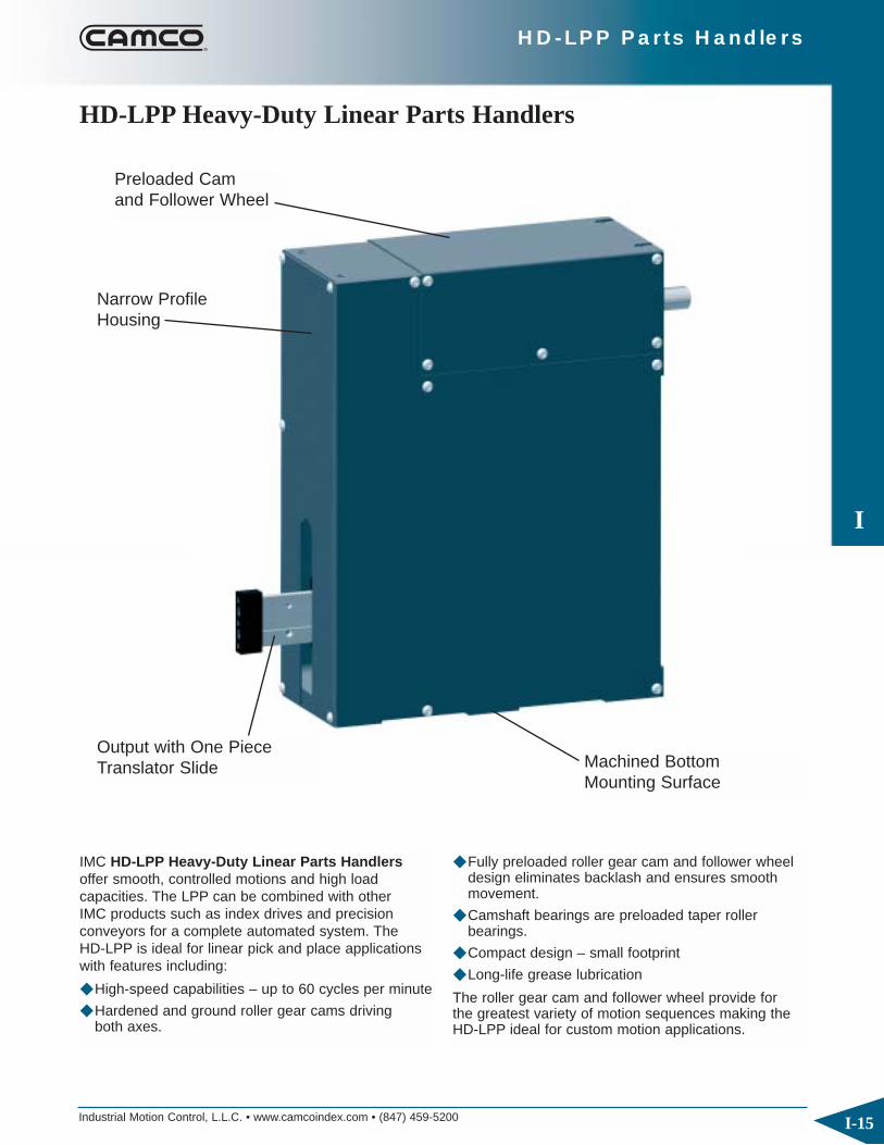
Industrial Motion Control, L.L.C. • www.camcoindex.com • (847) 459-5200
I
I-15
HD-LPP Parts Handlers
IMC HD-LPP Heavy-Duty Linear Parts Handlersoffer smooth, controlled motions and high load capacities. The LPP can be combined with other IMC products such as index drives and precision conveyors for a complete automated system. The HD-LPP is ideal for linear pick and place applicationswith features including:
◆ High-speed capabilities – up to 60 cycles per minute
◆ Hardened and ground roller gear cams driving both axes.
◆ Fully preloaded roller gear cam and follower wheeldesign eliminates backlash and ensures smoothmovement.
◆ Camshaft bearings are preloaded taper roller bearings.
◆ Compact design – small footprint
◆ Long-life grease lubrication
The roller gear cam and follower wheel provide for the greatest variety of motion sequences making theHD-LPP ideal for custom motion applications.
HD-LPP Heavy-Duty Linear Parts Handlers
Preloaded Camand Follower Wheel
Narrow ProfileHousing
Output with One PieceTranslator Slide Machined Bottom
Mounting Surface
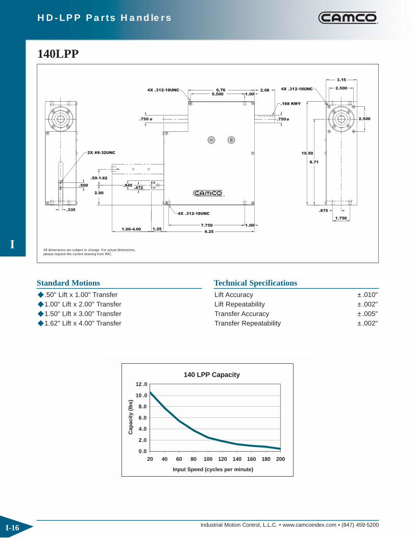
Industrial Motion Control, L.L.C. • www.camcoindex.com • (847) 459-5200
I
I-16
HD-LPP Parts Handlers
9.25
7.750
4X .312-18UNC
.50-1.62
2X #8-32UNC
.335
.500
2.00
1.251.00-4.00
.945.472
.750 ø
4X .312-18UNC
10.50
1.00
1.750
.875
8.71
4X .312-18UNC
1.005.500
.750 ø
.188 KWY
6.76 2.08
2.500
3.15
2.500
140LPP
All dimensions are subject to change. For actual dimensions,please request the current drawing from IMC.
Standard Motions◆ .50" Lift x 1.00" Transfer◆ 1.00" Lift x 2.00" Transfer◆ 1.50" Lift x 3.00" Transfer◆ 1.62" Lift x 4.00" Transfer
Technical SpecificationsLift Accuracy ±.010"Lift Repeatability ±.002"Transfer Accuracy ±.005"Transfer Repeatability ±.002"
0.0
2.0
4.0
6.0
8.0
10 .0
12 .0
20 40 60 80 100 120 140 160 180 200
Cap
acit
y (l
bs)
140 LPP Capacity
Input Speed (cycles per minute)

Industrial Motion Control, L.L.C. • www.camcoindex.com • (847) 459-5200
I
I-17
HD-LPP Parts Handlers
ø 4.29
1.202.34
ø 9MM
3.15
2.68
INVERTER DUTY1/8 HP MOTOR 6.14
28MM
RMI-28-FL
IEC 56B14
ø 14 MM
1.57 1.10
2.01
2.65
1.58
All dimensions are subject to change. For actual dimensions,please request the current drawing from IMC.
Standard Package◆ RMI-28-FL reducer (Ratios from 1/7 to 1/100)
— IEC 56B14 adapter◆ 1/8 hp Inverter Duty Motor
Optional Accessories◆ Reducer with double extended input◆ AC Inverter Duty Motor with AC Control◆ Belt-Driven DC Gearmotor
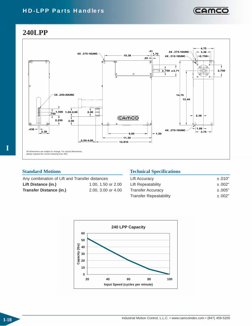
Industrial Motion Control, L.L.C. • www.camcoindex.com • (847) 459-5200
I
I-18
HD-LPP Parts Handlers
10.38
11.30
12.810
3X .250-20UNC
.4382.38
2.250
1.500.750
2.00-4.00
2.00
1.00-2.00 2.00
4X .375-16UNC
12.44
1.009.00
4X .375-16UNC
14.75
3.75
1.88
2.38
4X .375-16UNC
.22
ø 2.71ø .750
1.70.41
4X .312-18UNC
2.750
3.38
2.750
4.75
240LPP
All dimensions are subject to change. For actual dimensions,please request the current drawing from IMC.
Standard MotionsAny combination of Lift and Transfer distancesLift Distance (in.) 1.00, 1.50 or 2.00Transfer Distance (in.) 2.00, 3.00 or 4.00
Technical SpecificationsLift Accuracy ±.010"Lift Repeatability ±.002"Transfer Accuracy ±.005"Transfer Repeatability ±.002"
0
10
20
30
40
50
60
20 40 60 80 100
Cap
acit
y (l
bs)
240 LPP Capacity
Input Speed (cycles per minute)

Industrial Motion Control, L.L.C. • www.camcoindex.com • (847) 459-5200
I
I-19
HD-LPP Parts Handlers
IEC71 B14
19MM
90VOLT D.C.1900RPM MOTOR
GEAR REDUCERCAMCO R180
ø
2.00
2.50 1.78
4.31
1.30
9.22
12.44
1.75
3.44
3.64
14MM
1.91
All dimensions are subject to change. For actual dimensions,please request the current drawing from IMC.
Standard Package240LPP with◆ Standard Motion Sequence◆ R180 Reducer (Ratios from 5:1 to 60:1)◆ 1/3 hp DC Motor◆ Varipak DC Motor Control (up to 30 cpm)
Optional Accessories◆ LF-RMI-40-F1 Reducer (1/7 to 1/100)
— Optional Internal Overload Clutch— 1/4 hp Inverter Duty AC Brake Motor
◆ 1/3 hp AC Drive Package with Inverter Duty Motor and Inverter Drive (up to 60 cpm)
◆ 180-IOC Input Overload Clutch◆ Digi-Dog Digital Programmable Limit Switch◆ Camtronics Rotary Limit Switch

Industrial Motion Control, L.L.C. • www.camcoindex.com • (847) 459-5200
I
I-20
HD-LPP Parts Handlers
5.00-8.00
.750
2.63
.438
3.25
1.500
2.38
3X .250-20UNC
1.00-3.002.00
17.62
16.00
14.50
17.375
.59
2.384X .375-16UNC
3.25
2.38
4X .375-16UNC
ø 1.188
4X .375-16UNC14.50.50
3.50
.596.50
4.00
4.75
ø 3.719
20.88
.250 KWY
4.00
380LPP
All dimensions are subject to change. For actual dimensions,please request the current drawing from IMC.
Standard MotionsAny combination of Lift and Transfer distancesLift Distance (in.) 1.00, 2.00 or 3.00Transfer Distance (in.) 5.00, 6.00, 7.00 or 8.00
Technical SpecificationsLift Accuracy ±.010"Lift Repeatability ±.002"Transfer Accuracy ±.005"Transfer Repeatability ±.002"
0
5
10
15
20
25
30
35
20 40 60 80
Cap
acit
y (l
bs)
380 LPP Capacity
Input Speed (cycles per minute)

Industrial Motion Control, L.L.C. • www.camcoindex.com • (847) 459-5200
I
I-21
HD-LPP Parts Handlers
GEAR REDUCERCAMCO R225
90 VOLT D.C.1800RPM1HP MOTOR
5.25ø
13.10
.875ø 4.81
& COUPLING56C ADAPTOR
6.62ø
7.50
2.753.44 2.62
17.62
3.31
.688ø
2.252.75
All dimensions are subject to change. For actual dimensions,please request the current drawing from IMC.
Standard Package380LPP with◆ Standard Motion Sequence◆ R225 Reducer (Ratios from 5:1 to 60:1)
— 56C Motor Adapter and Coupling◆ 1 hp DC Motor◆ Varipak DC Motor Control (up to 30 cpm)
Optional Accessories◆ LF-RMI-50-F2 Reducer (1/7 to 1/100)
— Optional Internal Overload Clutch— 1/2 hp Inverter Duty AC Brake Motor
◆ 1 hp AC Drive Package with Inverter Duty Motor and Inverter Drive (up to 60 cpm)
◆ 225-IOC Input Overload Clutch◆ Digi-Dog Digital Programmable Limit Switch◆ Camtronics Rotary Limit Switch

Industrial Motion Control, L.L.C. • www.camcoindex.com • (847) 459-5200
I
I-22
HD-LPP Parts Handlers
20.50
23.375
22.00
20.50
3x .250-20UNC
3.50
.500
3.25
.750 1.500
8.00-12.00
2.88
2.75
1.00-4.00
4X .375-16UNC
.59 2.38
3.25 2.38
4X .375-16UNC
4X .375-16UNC
26.19
ø 3.719
ø 1.188
.42.593.59
.250 KWY
22.94
4.00
4.004.756.50
4120LPP
All dimensions are subject to change. For actual dimensions,please request the current drawing from IMC.
Standard MotionsAny combination of Lift and Transfer distancesLift Distance (in.) 1.00, 2.00, 3.00 or 4.00Transfer Distance (in.) 8.00, 9.00, 10.00,
11.00 or 12.00
Technical SpecificationsLift Accuracy ±.012"Lift Repeatability ±.004"Transfer Accuracy ±.007"Transfer Repeatability ±.004"
0
20
40
60
80
100
120
20 40 60 80 100 120 140
Cap
acit
y (l
bs)
4120 LPP Capacity
Input Speed (cycles per minute)

Industrial Motion Control, L.L.C. • www.camcoindex.com • (847) 459-5200
I
I-23
HD-LPP Parts Handlers
2.75
5.25
6.62
ø
ø
GEAR REDUCERCAMCO R225
3.44
90 VOLT D.C.1800 RPM1HP MOTOR
13.10
22.94
ø 4.81.875
& COUPLING56C ADAPTOR
7.50
2.62
ø.688
3.25
2.752.25
All dimensions are subject to change. For actual dimensions,please request the current drawing from IMC.
Standard Package4120LPP with◆ Standard Motion Sequence◆ R225 Reducer (Ratios from 5:1 to 60:1)
— 56C Motor Adapter and Coupling◆ 1 hp DC Motor◆ Varipak DC Motor Control (up to 30 cpm)
Optional Accessories◆ LF-RMI-70-F3 Reducer (1/7 to 1/100)
— Optional Internal Overload Clutch— 1 hp Inverter Duty AC Brake Motor
◆ 1 hp AC Drive Package with Inverter Duty Motor and Inverter Drive (up to 60 cpm)
◆ 225-IOC Input Overload Clutch◆ Digi-Dog Digital Programmable Limit Switch◆ Camtronics Rotary Limit Switch

Industrial Motion Control, L.L.C. • www.camcoindex.com • (847) 459-5200
I
I-24
HD-LPP Parts Handlers
Input Rotation (deg)
Tra
nsfe
r (i
n.)
0"0
T
180 360
Lif
t (i
n.)
0"0
L
90 180 270 360
= Dwell
5
4 1
2
6
3Home (Start)
Up
Down
1 2 4 5
3 6
Extended
Retracted90 270
LPP Output
Standard Motion Sequence
Motion OptionsStandard starting position (home) at time 0 is at maximum lift (up) and fully retracted. ◆ The motion sequence can be mirrored in either the
lift or transfer axes or in both axes.— The mirrored lift starts in the down position.— The mirrored transfer starts extended.
◆ Custom motion times are also available – consult your Sales Agent for more information.

Industrial Motion Control, L.L.C. • www.camcoindex.com • (847) 459-5200
I
I-25
HD-LPP Parts Handlers
HD-LPP Ordering Procedure
Drive Package Ordering Procedure
Dwell=
4
5
3
6
2
1
Start/Home Position
Input
CCW
AE:
AE:AE:
AE: Input Shaft AS: Output Shaft
AE:
AE:
AE:
AS:
1 2
3 4
5 6
AS:AS:
AS:
AS:
AS:
CW (Standard)
Position of Shafts Indexer Mounting Position
Standard Output Sequence
Input
C-1-LH D-1-LHA-1-LH B-1-LH G-1-RH H-1-RHE-1-RH F-1-RH
Reducer Mounting Position
1. Model Number
2. Input Shaft Rotation: CW or CCW
3. Lift and Transfer Distances (in.)
4. Motion Sequence & Home Position (standard is shown)
1. Reducer Model and Ratio
2. Reducer Mounting Position (A-H)
3. Motor Adaptor Model
4. Motor size

Industrial Motion Control, L.L.C. • www.camcoindex.com • (847) 459-5200
I
I-26
HD-LPP Parts Handlers

Industrial Motion Control, L.L.C. • www.camcoindex.com • (847) 459-5200
I
I-27
MR-LPP Parts Handlers
IMC Mid-Range Linear Parts Handlers (MR-LPP)are ideal for linear pick and place motions. With theinput shaft extending from the side of the unit, multipleunits can be placed side-by-side and line shaft drivenwith timing belts and pulleys.
◆ Lift and Transfer strokes can be adjusted in the fieldin 10 mm increments.
◆ Hardened and ground cams drive both axes.
◆ Preloaded, precision cam followers eliminate backlash and ensure smooth movement.
◆ Preloaded bushings (re-circulating ball type) support the internal carriage that drives the customer mounting surface. The ball bushings rideon hardened shafts providing stability and stiffness.
◆ Camshaft bearings are preloaded taper roller bearings.
◆ Compact Design
◆ Long-Life Grease Lubrication
Mid-Range Linear Parts Handlers
Low ProfileBlack AnodizedAluminum Housing
Side Input ShaftIdeal for LineShaft Applications
Linear Bearings
LargeMountingSurface
Black OxideSteel Cover

Industrial Motion Control, L.L.C. • www.camcoindex.com • (847) 459-5200
I
I-28
MR-LPP Parts Handlers
1.5
113
125
25
60
2X M5
15h8
2X ø5.83042
240
20010
50
1.5
20-90
12 75 75
4X M8
17.5 90
ø 20h7
10-50
ø 70h7
60 25
4X M8
4X M6
4X M8
ø 100
120
75
75
240
104
180 7
180
4X M8
6 X 3.5 N9
LPP-101
All dimensions are subject to change. For actual dimensions,please request the current drawing from IMC.
Standard Motions Technical SpecificationsLift Accuracy ±0.25mmLift Repeatability ±0.03mmTransfer Accuracy ±0.64mmTransfer Repeatability ±0.12mm
0
1
2
3
4
5
6
20 40 60 80 100 120 140 160
LPP-101 Capacity
Input Speed (cycles per minute)
Cap
acit
y (l
bs)
Any combination of Lift and Transfer distancesLift Distance (mm) 10, 20, 30, 40, 50Transfer Distance (mm) 20, 30, 40, 50, 60,
70, 80, 90
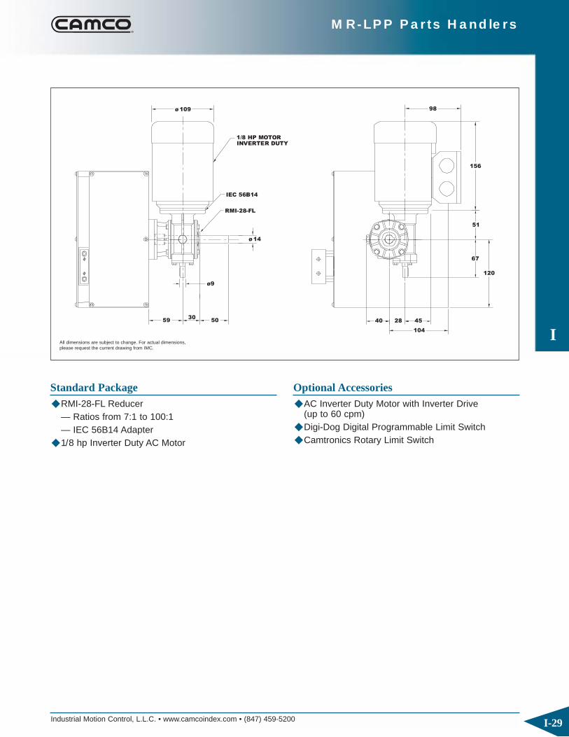
Industrial Motion Control, L.L.C. • www.camcoindex.com • (847) 459-5200
I
I-29
MR-LPP Parts Handlers
5930
50
RMI-28-FL
ø9
ø 14
ø 109
IEC 56B14
1/8 HP MOTORINVERTER DUTY
40
104
4528
120
67
51
156
98
All dimensions are subject to change. For actual dimensions,please request the current drawing from IMC.
Standard Package◆ RMI-28-FL Reducer
— Ratios from 7:1 to 100:1— IEC 56B14 Adapter
◆ 1/8 hp Inverter Duty AC Motor
Optional Accessories◆ AC Inverter Duty Motor with Inverter Drive
(up to 60 cpm)◆ Digi-Dog Digital Programmable Limit Switch◆ Camtronics Rotary Limit Switch
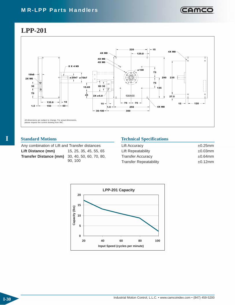
Industrial Motion Control, L.L.C. • www.camcoindex.com • (847) 459-5200
I
I-30
MR-LPP Parts Handlers
1.5
132.6
150
2X M6
70
30
18h8
2X ø6.8
60
10
30-100
15
1.5
15-65
ø 75h7ø 25h7
80
45
30
4X M6
4X M8
4X M8
ø 100
27.5
235
300
75 75
250 4X M8
75
145
75
290
15 120
4X M8129.8
220 15
8 X 4 N9
LPP-201
All dimensions are subject to change. For actual dimensions,please request the current drawing from IMC.
Standard Motions Technical SpecificationsLift Accuracy ±0.25mmLift Repeatability ±0.03mmTransfer Accuracy ±0.64mmTransfer Repeatability ±0.12mm
0
5
10
15
20
20 40 60 80 100
LPP-201 Capacity
Input Speed (cycles per minute)
Cap
acit
y (l
bs)
Any combination of Lift and Transfer distancesLift Distance (mm) 15, 25, 35, 45, 55, 65Transfer Distance (mm) 30, 40, 50, 60, 70, 80,
90, 100
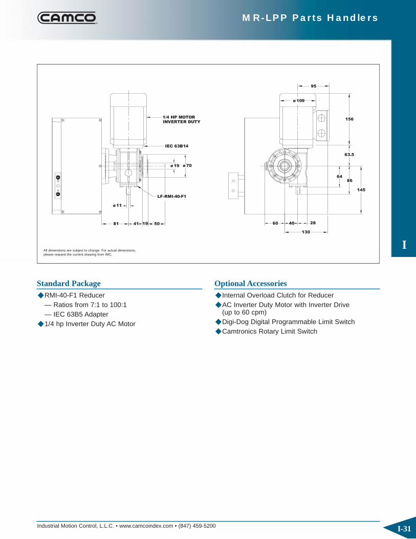
Industrial Motion Control, L.L.C. • www.camcoindex.com • (847) 459-5200
I
I-31
MR-LPP Parts Handlers
ø 11
5081 1941
LF-RMI-40-F1
ø 19 ø 70
IEC 63B14
INVERTER DUTY1/4 HP MOTOR
63.5
130
60 40 28
8664
145
ø 109
156
95
All dimensions are subject to change. For actual dimensions,please request the current drawing from IMC.
Standard Package◆ RMI-40-F1 Reducer
— Ratios from 7:1 to 100:1— IEC 63B5 Adapter
◆ 1/4 hp Inverter Duty AC Motor
Optional Accessories◆ Internal Overload Clutch for Reducer◆ AC Inverter Duty Motor with Inverter Drive
(up to 60 cpm)◆ Digi-Dog Digital Programmable Limit Switch◆ Camtronics Rotary Limit Switch

Industrial Motion Control, L.L.C. • www.camcoindex.com • (847) 459-5200
I
I-32
MR-LPP Parts Handlers
ø 30h725h8
1.5 175
154.3
2X M8
95
30
75
20
50-150
20
1.5
65
15-75
ø100h7
2X ø8.8
3090
4X M10
4X M10
4X M10
400
120120
170.6
390
330
4X M10
55
120
200
14515
5555
55
120
300 10
4X M10
8 X 4 N9
LPP-301
All dimensions are subject to change. For actual dimensions,please request the current drawing from IMC.
Standard Motions Technical SpecificationsLift Accuracy ±0.25mmLift Repeatability ±0.03mmTransfer Accuracy ±0.64mmTransfer Repeatability ±0.12mm
0
30
60
90
120
150
180
20 40 60 80 100 120
Input Speed (cycles per minute)
Cap
acit
y (l
bs)
LPP-301 Capacity
Any combination of Lift and Transfer distancesLift Distance (mm) 15, 25, 35, 45, 55, 65, 75Transfer Distance (mm) 50, 70, 90, 110, 130, 150

Industrial Motion Control, L.L.C. • www.camcoindex.com • (847) 459-5200
I
I-33
MR-LPP Parts Handlers
93
ø 14
5052 5022
LF-RMI-50-F2
71 34
IEC 71B14
ø 24 ø 90
INVERTER DUTY1/3 HP MOTOR
77
71104
176
ø124
All dimensions are subject to change. For actual dimensions,please request the current drawing from IMC.
Standard Package◆ RMI-50-F2 Reducer
— Ratios from 7:1 to 100:1— IEC 71B5 Adapter
◆ 1/2 hp Inverter Duty AC Motor
Optional Accessories◆ Internal Overload Clutch for Reducer◆ AC Inverter Duty Motor with Inverter Drive
(up to 60 cpm)◆ Digi-Dog Digital Programmable Limit Switch◆ Camtronics Rotary Limit Switch

Industrial Motion Control, L.L.C. • www.camcoindex.com • (847) 459-5200
I
I-34
MR-LPP Parts Handlers
1.5
220
191
2X M12
60
110
30h8
110
30
130-250
25
1.5
75
25-75
ø 140h7
60130
4X M12
ø 40h7
4X M12
570
70
540
470
231.8 4X M12
285
70
14 190
7070
435 124X M12
12 X 5 N9
LPP-401
All dimensions are subject to change. For actual dimensions,please request the current drawing from IMC.
Standard Motions Technical SpecificationsLift Accuracy ±0.25mmLift Repeatability ±0.03mmTransfer Accuracy ±0.64mmTransfer Repeatability ±0.12mm
0
50
100
150
200
250
20 40 60 80
LPP-401 Capacity
Input Speed (cycles per minute)
Cap
acit
y (l
bs)
Any combination of Lift and Transfer distancesLift Distance (mm) 25, 35, 45, 55, 65, 75Transfer Distance (mm) 130, 150, 170, 190, 210,
230, 250
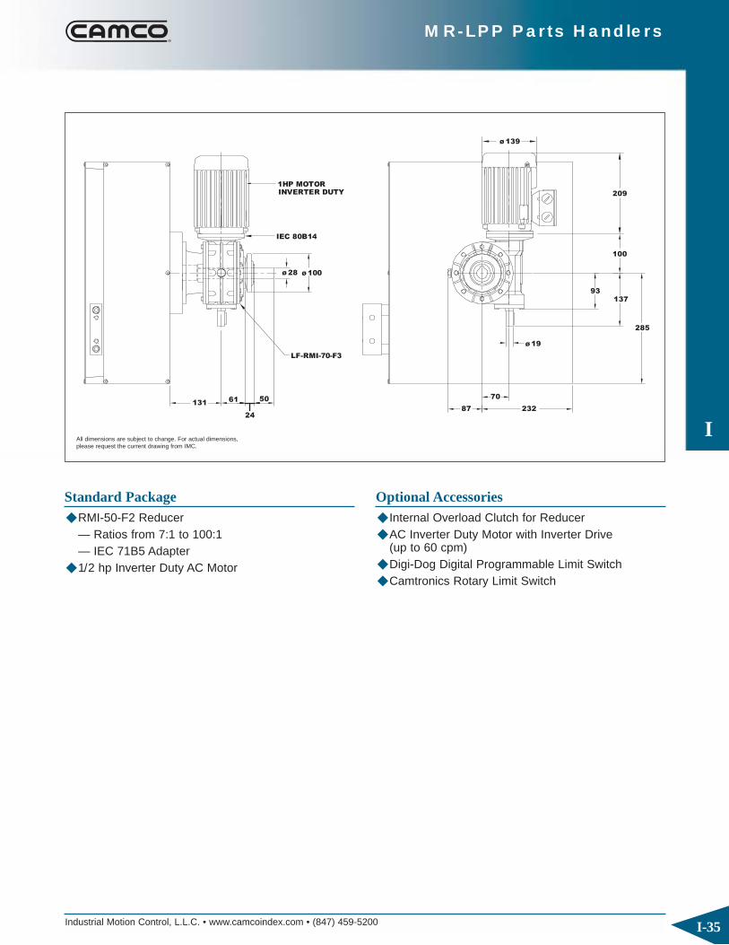
Industrial Motion Control, L.L.C. • www.camcoindex.com • (847) 459-5200
I
I-35
MR-LPP Parts Handlers
24
6113150
LF-RMI-70-F3
ø 100ø 28
IEC 80B14
1HP MOTORINVERTER DUTY
23287
70
ø 19
93137
285
ø 139
100
209
All dimensions are subject to change. For actual dimensions,please request the current drawing from IMC.
Standard Package◆ RMI-50-F2 Reducer
— Ratios from 7:1 to 100:1— IEC 71B5 Adapter
◆ 1/2 hp Inverter Duty AC Motor
Optional Accessories◆ Internal Overload Clutch for Reducer◆ AC Inverter Duty Motor with Inverter Drive
(up to 60 cpm)◆ Digi-Dog Digital Programmable Limit Switch◆ Camtronics Rotary Limit Switch

Industrial Motion Control, L.L.C. • www.camcoindex.com • (847) 459-5200
I
I-36
MR-LPP Parts Handlers
Input Rotation (deg)
Tra
nsfe
r (i
n.)
0"0
T
180 360
Lif
t (i
n.)
0"0
L
90 180 270 360
= Dwell
5
4 1
2
6
3Home (Start)
Up
Down
1 2 4 5
3 6
Extended
Retracted90 270
LPP Output
Standard Motion Sequence
Motion OptionsStandard starting position (home) at time 0 is at maximum lift (up) and fully retracted. ◆ The motion sequence can be mirrored in either the
lift or transfer axes or in both axes.— The mirrored lift starts in the down position.— The mirrored transfer starts extended.
◆ Custom motion times are also available – consult your Sales Agent for more information.

Industrial Motion Control, L.L.C. • www.camcoindex.com • (847) 459-5200
I
I-37
MR-LPP Parts Handlers
MR-LPP Ordering Procedure
Dwell=
4
5
3
6
2
1
Start/Home Position
Inpu CCW
CW
AS:
AS:
AS:
AS:
AS:
AS:AE:
AE:
AE:
AE: Input Shaft AS: Output Shaft
AE:
AE:
AE:
CW Standardt
Standard Output Sequence
Position of Shafts Indexer Mounting Position
1 2 (Standard)
1. Model Number
2. Lift and Transfer Distances (mm)
3. Motion Sequence & Home Position (standard is shown)
Drive Package Ordering Procedure
B-1-RH B-1-LHA-1-RH A-1-LH E-1-RH E-1-LHD-1-RH D-1-LH
E-2-LHE-2-RHD-2-LHD-2-RHB-2-LHB-2-RHA-2-LHA-2-RH
Reducer Mounting Position
1. Reducer Model, Ratio and Mounting Position
2. Motor Adaptor Model
3. Motor size

Industrial Motion Control, L.L.C. • www.camcoindex.com • (847) 459-5200
I
I-38
MR-LPP Parts Handlers
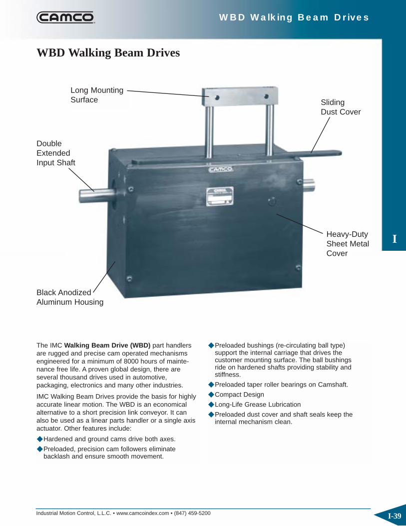
Industrial Motion Control, L.L.C. • www.camcoindex.com • (847) 459-5200
I
I-39
WBD Walking Beam Drives
The IMC Walking Beam Drive (WBD) part handlersare rugged and precise cam operated mechanismsengineered for a minimum of 8000 hours of mainte-nance free life. A proven global design, there are several thousand drives used in automotive, packaging, electronics and many other industries.
IMC Walking Beam Drives provide the basis for highlyaccurate linear motion. The WBD is an economicalalternative to a short precision link conveyor. It canalso be used as a linear parts handler or a single axisactuator. Other features include:
◆ Hardened and ground cams drive both axes.
◆ Preloaded, precision cam followers eliminate backlash and ensure smooth movement.
◆ Preloaded bushings (re-circulating ball type) support the internal carriage that drives the customer mounting surface. The ball bushingsride on hardened shafts providing stability and stiffness.
◆ Preloaded taper roller bearings on Camshaft.
◆ Compact Design
◆ Long-Life Grease Lubrication
◆ Preloaded dust cover and shaft seals keep the internal mechanism clean.
WBD Walking Beam Drives
Long MountingSurface
DoubleExtendedInput Shaft
Black AnodizedAluminum Housing
Heavy-DutySheet MetalCover
Sliding Dust Cover

Industrial Motion Control, L.L.C. • www.camcoindex.com • (847) 459-5200
I
I-40
WBD Walking Beam Drives
20
2X ø5
2X 45
100
2X ø 20h717
175
165 5
6 X 3.5 N9
85 19.6
2X M4 X 8
15-25
10
18.548
25-50
4X M6 X 12 100
46
135
95
167
ø 80
35
6
4X M5 X 10
4X M6 X 12
15h7
7
25
120
41
WBD-101
Standard Motions Technical SpecificationsLift Accuracy ±0.25mmLift Repeatability ±0.05mmTransfer Accuracy ±0.13mmTransfer Repeatability ±0.05mm
0
10
20
30
40
50
30 70 110 150 190 230 270
Cap
acit
y (l
bs)
WBD-101 Capacity
Input Speed (cycles per minute)
Any combination of Lift and Transfer distancesLift Distance (mm) 15, 20, 25Transfer Distance (mm) 25, 38, 50
All dimensions are subject to change. For actual dimensions, please request the current drawing from IMC.

Industrial Motion Control, L.L.C. • www.camcoindex.com • (847) 459-5200
I
I-41
WBD Walking Beam Drives
ø 14
44
69
ø9
28
95
51
41
49
40
68
109
15645 175 49 30
RMI-28-FL
IEC 56B14
1/8 HP A.C. INVERTER DUTY MOTOR
Standard Package◆ RMI-28-FL reducer
— Ratios from 7:1 to 100:1— IEC 56B14 adapter
◆ 1/8 hp Inverter Duty AC Motor◆ Cycle Cam and Limit Switch
Optional Accessories◆ AC Inverter Duty Motor with Inverter Drive
(up to 60 cpm)◆ Digi-Dog Digital Programmable Limit Switch◆ Camtronics Rotary Limit Switch
All dimensions are subject to change. For actual dimensions, please request the current drawing from IMC.
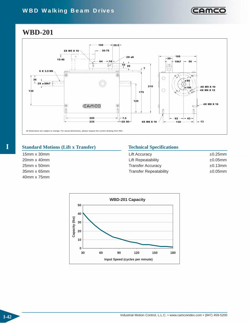
Industrial Motion Control, L.L.C. • www.camcoindex.com • (847) 459-5200
I
I-42
WBD Walking Beam Drives
15-40
2X ø 20h7
130
36
6 X 3.5 N9
4X M8 X 16
4X M8 X 16
220
235
7.5
2X 50
62
130
43
13
7
175
2X M5 X 10 30-75
64
125
10
18
20
2X ø6
100 29.5
ø 80
ø 100210
19h7
30160
4X M6 X 12
4X M5 X 10
56
WBD-201
Standard Motions (Lift x Transfer) Technical SpecificationsLift Accuracy ±0.25mmLift Repeatability ±0.05mmTransfer Accuracy ±0.13mmTransfer Repeatability ±0.05mm
0
10
20
30
40
50
30 60 90 120 150 180
WBD-201 Capacity
Cap
acit
y (l
bs)
Input Speed (cycles per minute)
15mm x 30mm20mm x 40mm25mm x 50mm35mm x 65mm40mm x 75mm
All dimensions are subject to change. For actual dimensions, please request the current drawing from IMC.

Industrial Motion Control, L.L.C. • www.camcoindex.com • (847) 459-5200
I
I-43
WBD Walking Beam Drives
LF-RMI-40-F1
ø 70
23550 69 95
41 19
ø 19
INVERTER DUTY 1/4 HP A.C. MOTOR
86 63.5
11ø40
28125
60
156
ø 109
IEC 63B14
Standard Package◆ RMI-40-F1 reducer
— Ratios from 7:1 to 100:1— IEC 63B5 adapter
◆ 1/4 hp Inverter Duty AC Motor◆ Cycle Cam and Limit Switch
Optional Accessories◆ Internal Overload Clutch for Reducer◆ AC Inverter Duty Motor with Inverter Drive
(up to 60 cpm)◆ Digi-Dog Digital Programmable Limit Switch◆ Camtronics Rotary Limit Switch
All dimensions are subject to change. For actual dimensions, please request the current drawing from IMC.
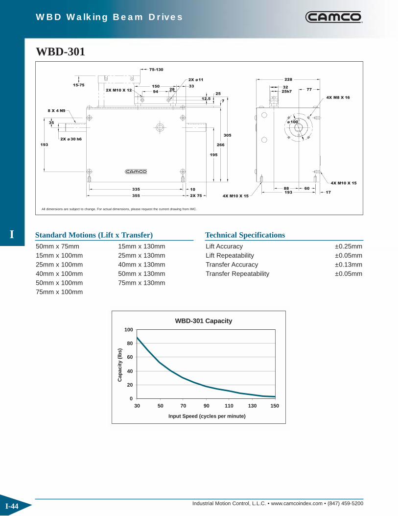
Industrial Motion Control, L.L.C. • www.camcoindex.com • (847) 459-5200
I
I-44
WBD Walking Beam Drives
4X M8 X 16
4X M10 X 15
35
193
2X ø 30 h6
8 X 4 N9
15-75
335
355
10
2X 75 4X M10 X 15
88 60193 17
25
266
195
2X ø11
94
1502X M10 X 12 28
33
12.5
75-130
228
305
7
ø 100
3225h7
77
WBD-301
Standard Motions (Lift x Transfer) Technical SpecificationsLift Accuracy ±0.25mmLift Repeatability ±0.05mmTransfer Accuracy ±0.13mmTransfer Repeatability ±0.05mm
0
20
40
60
80
100
30 50 70 90 110 130 150
WBD-301 Capacity
Cap
acit
y (l
bs)
Input Speed (cycles per minute)
50mm x 75mm15mm x 100mm25mm x 100mm40mm x 100mm50mm x 100mm75mm x 100mm
15mm x 130mm25mm x 130mm40mm x 130mm50mm x 130mm75mm x 130mm
All dimensions are subject to change. For actual dimensions, please request the current drawing from IMC.

Industrial Motion Control, L.L.C. • www.camcoindex.com • (847) 459-5200
I
I-45
WBD Walking Beam Drives
LF-RMI-50-F2
ø 90
75 355 73 52 22
ø 24
71
104 77
71
34
195
50 14
176
124
INVERTER DUTY1/3 HP MOTOR
IEC 71B14
Standard Package◆ RMI-50-F2 reducer
— Ratios from 7:1 to 100:1— IEC 71B5 adapter
◆ 1/2 hp Inverter Duty AC Motor◆ Cycle Cam and Limit Switch
Optional Accessories◆ Internal Overload Clutch for Reducer◆ AC Inverter Duty Motor with Inverter Drive
(up to 60 cpm)◆ Digi-Dog Digital Programmable Limit Switch◆ Camtronics Rotary Limit Switch
All dimensions are subject to change. For actual dimensions, please request the current drawing from IMC.

Industrial Motion Control, L.L.C. • www.camcoindex.com • (847) 459-5200
I
I-46
WBD Walking Beam Drives
2502X ø 40 h7
55
12 X 5 N9
525
15-1252X M12 X 20
100-200
150
225
2X 100
4X M12 X 20
25
260
455
10
375
4X M12 X 20
4X M10
4X M8
50
48.5
37.5
2X ø13
35h7
500 12 118.8
250
84
25
ø 130ø 165
108.7
50
300
WBD-401
All dimensions are subject to change. For actual dimensions, please request the current drawing from IMC.
Technical SpecificationsLift Accuracy ±0.25mmLift Repeatability ±0.05mmTransfer Accuracy ±0.13mmTransfer Repeatability ±0.05mm
0
20
40
60
80
100
30 40 50 60 70
WBD-401 Capacity
Cap
acit
y (l
bs)
Input Speed (cycles per minute)
Any combination of Lift and Transfer distancesLift Distance (mm) 15, 25, 40, 50, 75, 100, 125Transfer Distance (mm) 100, 125, 150, 200
Standard Motions

Industrial Motion Control, L.L.C. • www.camcoindex.com • (847) 459-5200
I
I-47
WBD Walking Beam Drives
LF-RMI-70-F3
ø 28
24100 525 101 61 109137
93 100
ø 19
260
ø 100
37
70
209
139
IEC 80B14
87
INVERTER DUTY1HP MOTOR
Standard Package◆ RMI-70-F3 reducer
— Ratios from 7:1 to 100:1— IEC 80B5 adapter
◆ 1 hp Inverter Duty AC Motor◆ Cycle Cam and Limit Switch
Optional Accessories◆ Internal Overload Clutch for Reducer◆ AC Inverter Duty Motor with Inverter Drive
(up to 60 cpm)◆ Digi-Dog Digital Programmable Limit Switch◆ Camtronics Rotary Limit Switch
All dimensions are subject to change. For actual dimensions, please request the current drawing from IMC.

Industrial Motion Control, L.L.C. • www.camcoindex.com • (847) 459-5200
I
I-48
WBD Walking Beam Drives
4013-125 170
250
12 X 5 N9
2X ø 40h7
55
645
670
2X M12 X 24
150-300
250
2X ø13
4X M12 X 24
12.5
2X 100
5025
255
455
375
300
1054X M12 X 24
25
130
ø 176
35h7
4X M12 X 24
5158 350
WBD-501
Technical SpecificationsLift Accuracy ±0.30mmLift Repeatability ±0.10mmTransfer Accuracy ±0.18mmTransfer Repeatability ±0.10mm
0
20
40
60
80
100
120
140
160
30 40 50 60 70 80 90 100
Cap
acit
y (l
bs)
WBD-501 Capacity
Input Speed (cycles per minute)
Any combination of Lift and Transfer distancesLift Distance (mm) 13, 25, 38, 50, 75, 100, 125Transfer Distance (mm) 150, 200, 250, 300
Standard Motions
All dimensions are subject to change. For actual dimensions, please request the current drawing from IMC.

Industrial Motion Control, L.L.C. • www.camcoindex.com • (847) 459-5200
I
I-49
WBD Walking Beam Drives
100 670 120 61116
23165
111
ø 24
25544
ø 32 ø110
85
247
IEC 90B14
ø 157
130LF-RMI-85-F2 145
INVERTER DUTY1.5 HP MOTOR
Standard Package◆ RMI-70-F3 reducer
— Ratios from 7:1 to 100:1— IEC 80B5 adapter
◆ 1 hp Inverter Duty AC Motor◆ Cycle Cam and Limit Switch
Optional Accessories◆ Internal Overload Clutch for Reducer◆ AC Inverter Duty Motor with Inverter Drive
(up to 60 cpm)◆ Digi-Dog Digital Programmable Limit Switch◆ Camtronics Rotary Limit Switch
All dimensions are subject to change. For actual dimensions, please request the current drawing from IMC.
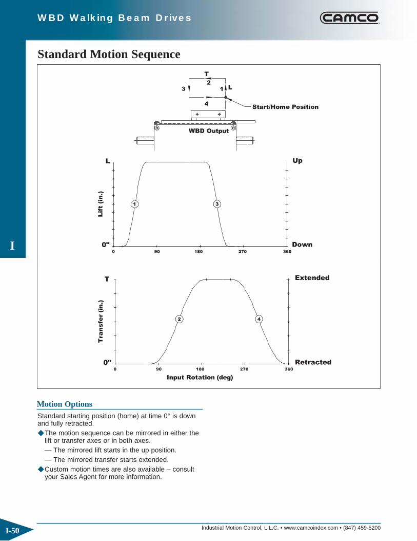
Industrial Motion Control, L.L.C. • www.camcoindex.com • (847) 459-5200
I
I-50
WBD Walking Beam Drives
Start/Home Position
L
T
360
0"90
0"0
Tra
nsfe
r (i
n.)
T
0
Input Rotation (deg)
90 180 270
180 270
Lif
t (i
n.)
L
3
4
1
WBD Output
2
Down
Retracted360
Extended
Up
1 3
2 4
Standard Motion Sequence
Motion OptionsStandard starting position (home) at time 0° is downand fully retracted. ◆ The motion sequence can be mirrored in either the
lift or transfer axes or in both axes.— The mirrored lift starts in the up position.— The mirrored transfer starts extended.
◆ Custom motion times are also available – consult your Sales Agent for more information.

Industrial Motion Control, L.L.C. • www.camcoindex.com • (847) 459-5200
I
I-51
WBD Walking Beam Drives
WBD Ordering Procedure
Input
Standard Output Sequence
Position of Shafts Indexer Mounting Position
Start/home Position
InpuCCW
AS:
AS:
AS:AS:
AS:
AS:
AE:
AE:
AE:AE:
AE:
AE:
1 2
DI (Standard)
CW (Standard)t
1
3
5
AE: Input Shaft AS: Output Shaft
6
4
2
1. Model Number
2. Lift and Transfer Distances (mm)
3. Motion Sequence & Home Position (standard is shown)
Drive Package Ordering Procedure
B-1-RH B-1-LHA-1-RH A-1-LH D-1-RH D-1-LHC-1-RH C-1-LH
D-2-LHD-2-RHC-2-LHC-2-RHB-2-LHB-2-RHA-2-LHA-2-RH
Reducer Mounting Position
1. Reducer Model, Ratio and Mounting Position
2. Motor Adaptor Model
3. Motor size

Industrial Motion Control, L.L.C. • www.camcoindex.com • (847) 459-5200
I
I-52
WBD Walking Beam Drives
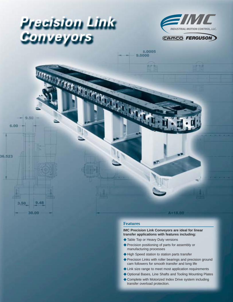
FeaturesIMC Precision Link Conveyors are ideal for linear transfer applications with features including:
◆ Table Top or Heavy Duty versions
◆ Precision positioning of parts for assembly or manufacturing processes
◆ High Speed station to station parts transfer
◆ Precision Links with roller bearings and precision groundcam followers for smooth transfer and long life
◆ Link size range to meet most application requirements
◆ Optional Bases, Line Shafts and Tooling Mounting Plates
◆ Complete with Motorized Index Drive system including transfer overload protection.

Industrial Motion Control, L.L.C. • www.camcoindex.com • (847) 459-5200
J
J-2
Precision Link Conveyors
IMC Precision Link Conveyors combine excellentaccuracy and high load capability with versatility tomeet any automation challenge. In combination with a IMC index drive package and IMC parts handlers,these conveyors can be relied on as the cornerstoneof in-line automatic assembly applications.
High Speed and AccuracyPrecision-machined conveyor chain links are driven bya high-performance IMC Index Drive. The Conveyorsare equipped with a precision machined chordal com-pensation cam which maintains a precise tension levelin the link assembly at all times for high accuracy andspeed capability
VersatilityMany Precision Link Conveyors features can be customized including conveyor length, index distance,index motion, link fixture mounting pattern, drive package component and drive package arrangement.In addition, custom options include tooling plates, lineshafts, and custom bases.
CustomizationTo suit your needs, IMC will design and build yourentiry precision conveyor sub-assembly, ready for your tooling. IMC parts handlers and auxiliary index drives can be mounted to work synchronously with the conveyor. IMC quality in every component ensuresthe highest accuracy and durability for your automa-tion application.
Precision LinksEach link of a precision conveyor is machined toIMC’s exacting standards. Roller bearings are built intothe link for smooth pivotal action between each link.Precise positioning is guaranteed by hardened groundcam followers pre-loaded against precision groundtracks in the conveyor body. All bearings are greasedand sealed for ease of maintenance and extended life.
Easy to ToolOptional tooling and parts handler mounting surfacesare available for easy, convenient machine building.
Compact DesignIn-line design saves floor space and provides maximum accessibility for tooling. Both Over/Underand Carousel design are available in lengths to meetyour needs.
Precision Link Conveyors

Industrial Motion Control, L.L.C. • www.camcoindex.com • (847) 459-5200
J
J-3
Precision Link Conveyors
IMC Table Top Precision Link Conveyors are availablein a variety of standard configurations. Standard linklengths include: 1.5", 2.0", 3.0", 4.5" and 6.0". Table Top Conveyor Modules are available with andwithout a drive package. They can be oriented in anydirection without affecting capacity, accuracy or easeof maintenance. Typically, they are mounted directly to the top surface or wall of your machined base.Table Top Conveyor drive packages feature a shrink-disk mounted output overload clutch offering a zero-backlash connection between the indexer andthe conveyor. It also provides phase adjustability andadded protection for the indexer.
The Table Top Conveyor configurations shown hereare intended as a general guideline in the design ofyour automation system. Your IMC Sales Agent willhelp you determine any options or customer modifica-tion you may require.
Table Top Precision Link Conveyors

Industrial Motion Control, L.L.C. • www.camcoindex.com • (847) 459-5200
J
J-4
Precision Link Conveyors
1.5 Basic Module
A
A
.625
1.250
4X #8-32UNC X .25
1.5000
2X ø.1250 X .25
-.0000+.0005
±.0005
STANDARD = 36.00, 48.00, 60.00 & 72.00
6.670
4.50 4.50
3.626.31
4.50
3.45
2.25
3.75
2X ø.750
+.0000-.0005
KWY.188
4.50
8X .250-20UNC
2.25
1.12
1.12
R2.8977
.750
.375
.750
.06
4.501.500
All dimensions are subject to change. For actual dimensions, please request the current drawing from IMC.
Standard Drive Package (Over/Under & Carousel)◆ 400RA Index Drive◆ 2.3FC-SD Overload Clutch◆ R180 Gear Reducer◆ 1/3 hp DC Motor◆ Varipak DC Motor Control
Heavy Duty Drive Package(Over/Under)◆ 250P Index Drive◆ .39FC-SD Overload Clutch◆ R180 Gear Reducer◆ 1/3 hp DC Motor◆ Varipak DC Motor Control
Index Distance (in.) Indexer Stops
1.5 12
3 6
4.5 4
6 3
9 2
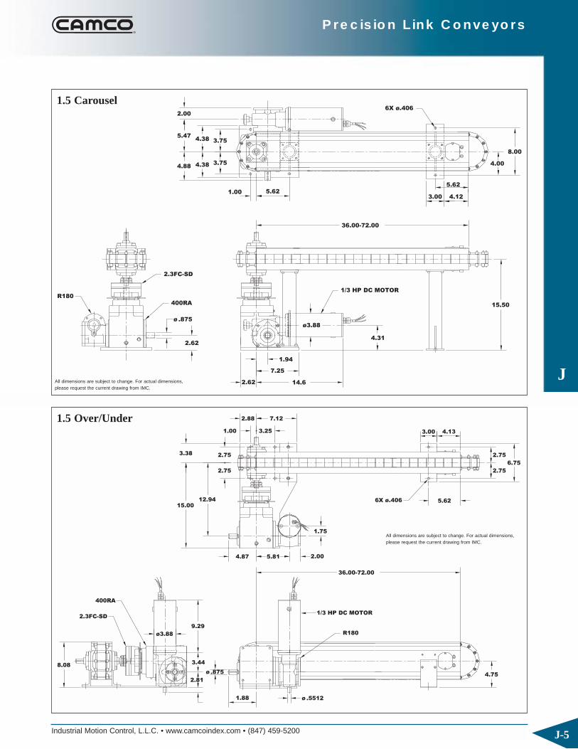
J
Precision Link Conveyors
Industrial Motion Control, L.L.C. • www.camcoindex.com • (847) 459-5200 J-5
1.94
R180
2.62
2.62
7.25
2.3FC-SD
400RA
ø .875
4.384.88
1.00
3.75
5.62
4.385.47
2.00
3.75
4.31
14.6
1/3 HP DC MOTOR
ø3.88
15.50
3.00
36.00-72.00
6X ø.406
8.00
4.12
5.62
4.00
All dimensions are subject to change. For actual dimensions, please request the current drawing from IMC.
8.08
400RA
2.3FC-SD
ø .875
2.81
1.88
9.29
ø3.88
3.44
2.75
15.0012.94
4.87 5.81
2.753.38
1.00 3.25
2.88 7.12
36.00-72.00
ø .5512
1/3 HP DC MOTOR
R180
4.75
4.13
5.62
2.00
1.75
6X ø.406
3.00
2.75
2.75
6.75
All dimensions are subject to change. For actual dimensions, please request the current drawing from IMC.
1.5 Carousel
1.5 Over/Under

Industrial Motion Control, L.L.C. • www.camcoindex.com • (847) 459-5200
J
J-6
Precision Link Conveyors
2.0 Basic Module
STANDARD = 72.00, 84.00, 96.00, & 108.00
.375 KWY
-.0005+.0000
3.004.008X .375-16UNC
.250 KWY
3.0005.75
+.0000-.0005
±.0005
2.0000
6.003.00
2X .250-20UNC
2X ø.2500 X .50
+.0005-.00001.000
8.97
6.626.32
5 75
3.00
ø1.4375
4.62
3.75
ø1.000
2.5003.0001.250
2.75
R3.8637
A
A
.750
.375
.060
2.000
All dimensions are subject to change. For actual dimensions, please request the current drawing from IMC.
Index Distance (in.) Indexer Stops
2 12
4 6
6 4
8 3
Standard Drive Package (Over/Under & Carousel)◆ 401RA Index Drive◆ 2.3FC-SD Overload Clutch◆ R225 Gear Reducer◆ 1 hp DC Motor◆ Varipak DC Motor Control
Heavy Duty Drive Package(Over/Under & Carousel)◆ 512RA Index Drive◆ 6.0FC-SD Overload Clutch◆ R260 Gear Reducer◆ 1 hp DC Motor◆ Varipak DC Motor Control
Standard Drive Package(Over/Under)◆ 387P Index Drive◆ 2.3FC-SD Overload Clutch◆ R260 Gear Reducer◆ 1 hp DC Motor◆ Varipak DC Motor Control
Heavy Duty Drive Package(Over/Under)◆ 512P Index Drive◆ 6.0FC-SD Overload Clutch◆ R260 Gear Reducer◆ 1 hp DC Motor◆ Varipak DC Motor Control
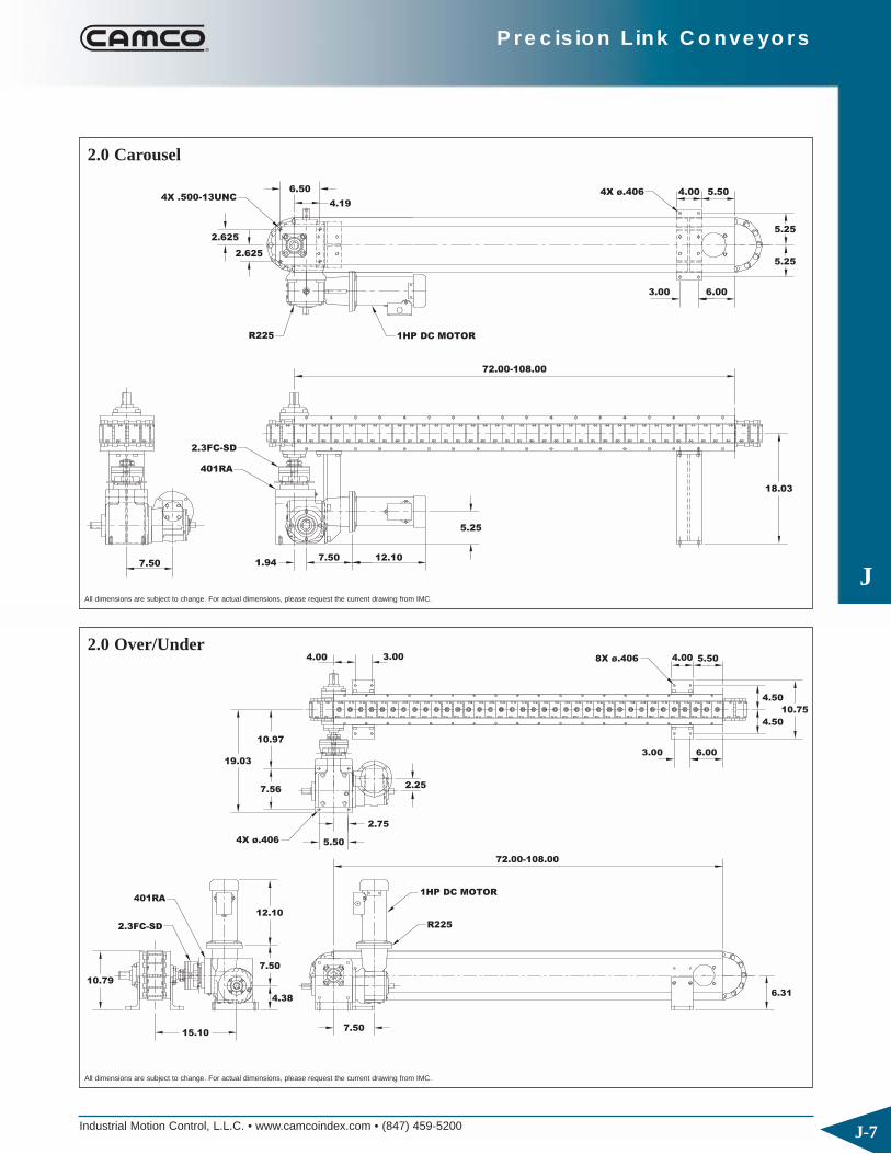
Industrial Motion Control, L.L.C. • www.camcoindex.com • (847) 459-5200
J
J-7
Precision Link Conveyors
1HP DC MOTOR
2.3FC-SD
7.50 1.947.50 12.10
401RA
4X .500-13UNC
2.625
R225
6.50
2.625
4.19
5.25
18.03
3.00
72.00-108.00
4X ø.406
6.00
5.25
4.00 5.50
5.25
1HP DC MOTOR
R225
15.10
10.79
401RA
2.3FC-SD
7.50
7.50
4.38
12.10
10.97
5.504X ø.406
7.56
19.03
2.75
2.25
4.00 3.00
6.31
4.00
72.00-108.00
3.00
8X ø.406
6.00
10.75
5.50
4.50
4.50
All dimensions are subject to change. For actual dimensions, please request the current drawing from IMC.
All dimensions are subject to change. For actual dimensions, please request the current drawing from IMC.
2.0 Carousel
2.0 Over/Under

Industrial Motion Control, L.L.C. • www.camcoindex.com • (847) 459-5200
J
J-8
Precision Link Conveyors
3.0 Basic Module
±
+.0000-.0005
-.0005+.0000
3.00
6.31
4.3.00
5.75
6.62
9.09
ø1.4375
4.62
3.005.75
3.75
ø1.000
.250 KWY
.375 KWY
STANDARD = 72.00, 84.00, 96,00, & 108.00
6.003.00
.00053.0000
1.500
.500
1.000
2.503.00
A
+.0005-.0000
2X .250-20UNC
2X ø.2500 X .50
.06
3.000
1.38
2.75
R3.9197
All dimensions are subject to change. For actual dimensions, please request the current drawing from IMC.
Index Distance (in.) Indexer Stops
3 8
6 4
9 2 2/3*
12 2
* Not available in Parallel Indexers.
Standard Drive Package (Over/Under & Carousel)◆ 401RA Index Drive◆ 2.3FC-SD Overload Clutch◆ R225 Gear Reducer◆ 1 hp DC Motor◆ Varipak DC Motor Control
Heavy Duty Drive Package(Over/Under & Carousel)◆ 512RA Index Drive◆ 6.0FC-SD Overload Clutch◆ R260 Gear Reducer◆ 1 hp DC Motor◆ Varipak DC Motor Control
Standard Drive Package(Over/Under)◆ 387P Index Drive◆ 2.3FC-SD Overload Clutch◆ R260 Gear Reducer◆ 1 hp DC Motor◆ Varipak DC Motor Control
Heavy Duty Drive Package(Over/Under)◆ 512P Index Drive◆ 6.0FC-SD Overload Clutch◆ R260 Gear Reducer◆ 1 hp DC Motor◆ Varipak DC Motor Control

Industrial Motion Control, L.L.C. • www.camcoindex.com • (847) 459-5200
J
J-9
Precision Link Conveyors
1HP DC MOTOR
2.3FC-SD
7.50 1.947.50 12.10
401RA
4X .500-13UNC
2.625
R225
6.50
2.625
4.19
5.25
18.03
3.00
72.00-108.00
4X ø.406
6.00
5.25
5.504.00
5.25
R225
1HP DC MOTOR
15.10
10.86
401RA
7.50
7 50
12.10
10.97
5.504X ø.406
7.56
19.03
2.75
5
4.00 3.00
6.31
4.00
72.00-108.00
3.00
8X ø.406
6.00
10.75
5.50
0
4.50
All dimensions are subject to change. For actual dimensions, please request the current drawing from IMC.
All dimensions are subject to change. For actual dimensions, please request the current drawing from IMC.
3.0 Carousel
3.0 Over/Under

Industrial Motion Control, L.L.C. • www.camcoindex.com • (847) 459-5200
J
J-10
Precision Link Conveyors
4.5 Basic Module
2X ø.2500 X .38
1.312
4.5000
±.0005
8X .375-16UNC
STANDARD = 72.00, 108.00, 126.00, 144.00, & 162.00
8.00 8.00
5.68
3.00
10.00
13.25
5.62
4.00 4.00
5.75
.500 KWY 2.000ø
-.0000
3.00 2.500
+.0005
4.00 8.00
6.00
A1.875
A
2.625
.938
.06
4.5000
2.250
4X .250-20UNC X .38
5
R5.879
All dimensions are subject to change. For actual dimensions, please request the current drawing from IMC.
Index Distance (in.) Indexer Stops
4.5 8
9 4
18 2
Standard Drive Package (Over/Under)◆ 662RA Index Drive◆ 11FC-SD Overload Clutch◆ 7300C Gear Reducer◆ 1 hp DC Motor◆ Varipak DC Motor Control
Standard Drive Package (Carousel)◆ 500RGD Index Drive◆ 11FC-SD Overload Clutch◆ 7300C Gear Reducer◆ 1 hp DC Motor◆ Varipak DC Motor Control

Industrial Motion Control, L.L.C. • www.camcoindex.com • (847) 459-5200
J
J-11
Precision Link Conveyors
11FC-SD
3.62
5.00
500RGD
7300C
8.88
4.06
8.50
4X .500-13UNC3.62
12.75
1HP DC MOTOR
8.00
21.66
5.50 9.56
72.00-162.00
12.25
4.00
4X ø.531 6.00
8.00
7.50
7.00
7.50
17.00
9.00
2.00
3.00
26.38
16.12
21.50
11FC-SD
662RA
1HP DC MOTOR
7300C
6.50
10.22
9.56
12.25
9.00
4X ø.531
6.00
4.50
72.00-162.00
9.50
4.00 8.00
4X ø.531 6.00 7.00
4.50
10.75
4.50
All dimensions are subject to change. For actual dimensions, please request the current drawing from IMC.
All dimensions are subject to change. For actual dimensions, please request the current drawing from IMC.
4.5 Carousel
4.5 Over/Under

Industrial Motion Control, L.L.C. • www.camcoindex.com • (847) 459-5200
J
J-12
Precision Link Conveyors
6.0 Basic Module
3.000
STANDARD = 72.00, 108.00, 144.00, &180.00
-.0000+.0005
2X ø.3120 X .62
8X .375-16UNC
13.875
9.00 9.00
4.00
7.756.38
4.50 4.00
.500 KWY
12.31 4.00
2.000ø2X
±.0005
6.0000
-.0005+.0000
4.00
4.00 8.00
3.006.00
4X .312-18UNC X .62
A
3.750
2.500
1.875
1.250 A
3.000
6.000
1.500
.06
R6.000
All dimensions are subject to change. For actual dimensions, please request the current drawing from IMC.
Index Distance (in.) Indexer Stops
6 6
12 3
18 2
Standard Drive Package (Over/Under & Carousel)◆ 662RA Index Drive◆ 11FC-SD Overload Clutch◆ 7300C Gear Reducer◆ 1 hp DC Motor◆ Varipak DC Motor Control
Heavy Duty Drive Package(Over/Under & Carousel)◆ 800RD Index Drive◆ 25FC-SD Overload Clutch◆ 7300C Gear Reducer◆ 1 hp DC Motor◆ Varipak DC Motor Control
Standard Drive Package (Over/Under)◆ 662RA Index Drive◆ 11FC-SD Overload Clutch◆ 7300C Gear Reducer◆ 1 hp DC Motor◆ Varipak DC Motor Control

Industrial Motion Control, L.L.C. • www.camcoindex.com • (847) 459-5200
J
J-13
Precision Link Conveyors
9.50
4.75
4X .500-13UNC11.00
6.81
662RA
7300C
11FC-SD
6.18
10.12
9.56
3.00
9.38
7.88
1HP DC MOTOR
28.06
72.00-180.00
12.10
8.004.00
4X ø.406 7.505.00
7.25
16.00
7.25
4.004.50
12.10
9.56
5.94
15.88
18.56 8.50 4X ø.562 X 1.064.75
9.50
14.19
1HP DC MOTOR
11FC-SD
662RA
4.88
10.12
23.19
8.75
72.00-180.00
7300C
8X ø.406
4.00 8.00
5.00 7.50
8.94
5.25
5.25
11.50
All dimensions are subject to change. For actual dimensions, please request the current drawing from IMC.
All dimensions are subject to change. For actual dimensions, please request the current drawing from IMC.
6.0 Carousel
6.0 Over/Under

Industrial Motion Control, L.L.C. • www.camcoindex.com • (847) 459-5200
J
J-14
Precision Link Conveyors

Industrial Motion Control, L.L.C. • www.camcoindex.com • (847) 459-5200
J
J-15
Precision Link Conveyors
IMC Heavy Duty Precision Link Conveyors are avail-able with standard link lengths of 6.0", 9.0" and 12".They are available in Over/Under and Carousel configurations. Both configurations include heavy-dutylegs and a precision machined base designed to holdlarge loads and maintain system accuracy. Adjustablesoft machine mounts are available on the base toaccommodate inconsistent on-site flooring.
The conveyor is available with either an “open backbone” or “closed backbone” design. The openbackbone allows for convenient passage of tooling,drive shafts, timing belts, and hydraulic, air or electrical lines through the center of the conveyor. The closed backbone design is ideally suited tomounted IMC parts handlers and tooling plates andoffers increased rigidity.
Like the Table Top Series, Heavy Duty Conveyors canbe mounted in any direction simply by modifying thesupports with no change in accuracy, load capacity ormaintenance requirements.
The Heavy Duty Conveyor configurations shown hereare intended as a general guideline in the design ofyour automation system. Your IMC Sales Agent willhelp you determine any options or customer modifica-tion you may require.
Heavy Duty Precision Link Conveyors

Industrial Motion Control, L.L.C. • www.camcoindex.com • (847) 459-5200
J
J-16
Precision Link Conveyors
6.0HD LINK
4.000
6.0000
1.8752.375
1.000
+.0005–.0000
2X ø.3120 X .62
4.750
±.0005
±.0005
.13
4X .375-16UNC
3.750
All dimensions are subject to change. For actual dimensions, please request the current drawing from IMC.
Index Distance (in.) Indexer Stops
6 12
12 6
18 4
24 3
Standard Drive Package◆ 242 Intermittor Index Drive◆ R400 Reducer◆ 5 hp AC Motor◆ MDB-1125 Air Clutch-Brake◆ Cycle Cam & Limit Switch

Industrial Motion Control, L.L.C. • www.camcoindex.com • (847) 459-5200
J
J-17
Precision Link Conveyors
STANDARD
7.75
A+24.00
12.00
7.75 3.000
17.50
35.00
38.00
9.25
24.00
9.50 4.75
42.75
ACROSS LINKS
216.00
24.43
288.00
144.00
A
26.432
6.0000
TYP36.00
±.0005
A
38.00
8.93
All dimensions are subject to change. For actual dimensions, please request the current drawing from IMC.
9.25
36.00
9.50
41.6819.22
17.50
35.00
38.00
4.75
ACROSS LINKS
±.0005
6.00003.000
A
A+54.00
TYP36.00
8.93 26.432
6.00
STANDARD
144.00
288.00
216.00
A
All dimensions are subject to change. For actual dimensions, please request the current drawing from IMC.
6.0 HD Carousel
6.0HD Over/Under

Industrial Motion Control, L.L.C. • www.camcoindex.com • (847) 459-5200
J
J-18
Precision Link Conveyors
9.0HD LINK
6.000
9.0000
1.8752.375
1.500
+.0005–.0000
2X ø.3120 X .62
4.750
±.0005
±.0005
.13
4X .375-16UNC
3.750
All dimensions are subject to change. For actual dimensions, please request the current drawing from IMC.
Index Distance (in.) Indexer Stops
9 12
18 6
27 4
36 3
Standard Drive Package◆ 242 Intermittor Index Drive◆ R400 Reducer◆ 5 hp AC Motor◆ MDB-1125 Air Clutch-Brake◆ Cycle Cam & Limit Switch
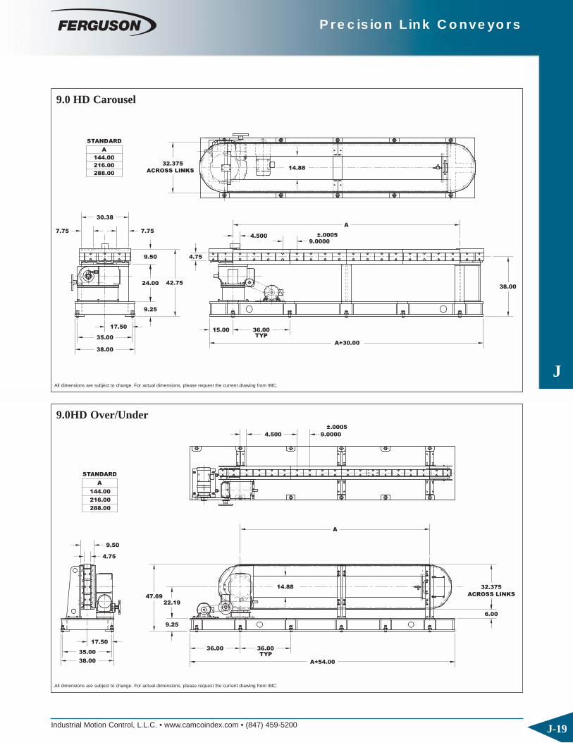
Industrial Motion Control, L.L.C. • www.camcoindex.com • (847) 459-5200
J
J-19
Precision Link Conveyors
4.500
38.00
35.00
17.50
9.25
15.00TYP
36.00
24.00 42.75
9.50 4.75
216.00
7.75
30.38
288.00
A
144.00
STANDARD
32.375
7.75
ACROSS LINKS
9.0000±.0005
A+30.00
38.00
A
14.88
All dimensions are subject to change. For actual dimensions, please request the current drawing from IMC.
9.25
36.00
9.50
47.6922.19
17.50
35.00
38.00
4.75
ACROSS LINKS
±.0005
9.00004.500
A
A+54.00
TYP36.00
14.88 32.375
6.00
STANDARD
144.00
288.00
216.00
A
All dimensions are subject to change. For actual dimensions, please request the current drawing from IMC.
9.0 HD Carousel
9.0HD Over/Under

Industrial Motion Control, L.L.C. • www.camcoindex.com • (847) 459-5200
J
J-20
Precision Link Conveyors
12.0HD LINK
2x ø.3120 x .62
±.0005
.06
4X .375-16UNC-.0000+.0005
±.0005
12.0000
1.8752.375
2.000
4.750
3.750
8.000
All dimensions are subject to change. For actual dimensions, please request the current drawing from IMC.
Index Distance (in.) Indexer Stops Sprocket
12 8, 10, 12 8T, 10T, 12T
24 4, 5, 6 8T, 10T, 12T
36 4 12T
48 2, 3 8T, 12T
Standard Drive Package◆ 242 Intermittor◆ R5 Reducer◆ 7.5 hp AC Motor◆ Posidyne Clutch-Brake◆ Brake Cam & Limit Switch

Industrial Motion Control, L.L.C. • www.camcoindex.com • (847) 459-5200
J
J-21
Precision Link Conveyors
6.000
38.00
35.00
17.50
9.25
18.00TYP
36.00
24.00 42.75
9.50 4.75
216.00
7.75
32.61
288.00
A
144.00
STANDARD
34.608
7.75
ACROSS LINKS
12.0000±.0005
A+36.00
38.00
A
17.11
All dimensions are subject to change. For actual dimensions, please request the current drawing from IMC.
9.25
36.00
9.50
49.8623.30
17.50
35.00
38.00
4.75
ACROSS LINKS
±.0005
12.00006.000
A
A+54.00
TYP36.00
17.11 34.608
6.00
STANDARD
144.00
288.00
216.00
A
All dimensions are subject to change. For actual dimensions, please request the current drawing from IMC.
12.0 HD Carousel
12.0HD Over/Under

Industrial Motion Control, L.L.C. • www.camcoindex.com • (847) 459-5200
J
J-22
Precision Link Conveyors
The following ordering procedure is intended as a general guideline for the minimum informationrequired when ordering a Precision Link Conveyor.
Ordering ProcedureYour IMC Sales Agent will help you clearly specifyany alterations you need to meet your design requirements.
Required Information◆ Link Size: 1.5, 2.0, 3.0, 4.5, 6.0, 9.0 or 12.0
◆ Type: Table Top or Heavy Duty
◆ Style: Over/Under or Carousel
◆ Length: Standard per catalog or Custom, expressed as center distance, in inches
◆ Height: Standard per catalog or Custom, in inches
Required Information when orderingDrive Package◆ Type: Standard, Alternate, Heavy-Duty or Special
◆ Drive Side: 1 or 2 (for Over/Under)
◆ Index Distance: In inches
◆ Indexer Model: Specific model number or special
Technical AssistanceAll Precision Link Conveyor applications are verifiedby a IMC sales agent using the IMC Sizing Program.
Your IMC agent is available to make all sizing calculations for you.

FeaturesIMC Servo-Mechanical Drives combine the flexibility of a servomotor with the accuracy and reliability of a cam-driven index drive. They can are ideal for dial, conveyor, or linkage applications. The drives are offered in severalconfigurations
◆ The Flex-i-Dex drive is a dedicated Servo-Mechanicalpackage complete with servomotor and amplifier ideal for light duty applications or short, fast movements.
◆ Constant Lead cam drives are standard RDM or HeavyDuty E-Series drives with constant lead (constant ratio)cams. Supplied with or without a reducer and servomotorpackage, they offer a large mounting surface, bearingsupport and thru-hole. Supply your own servo packageor use ours.
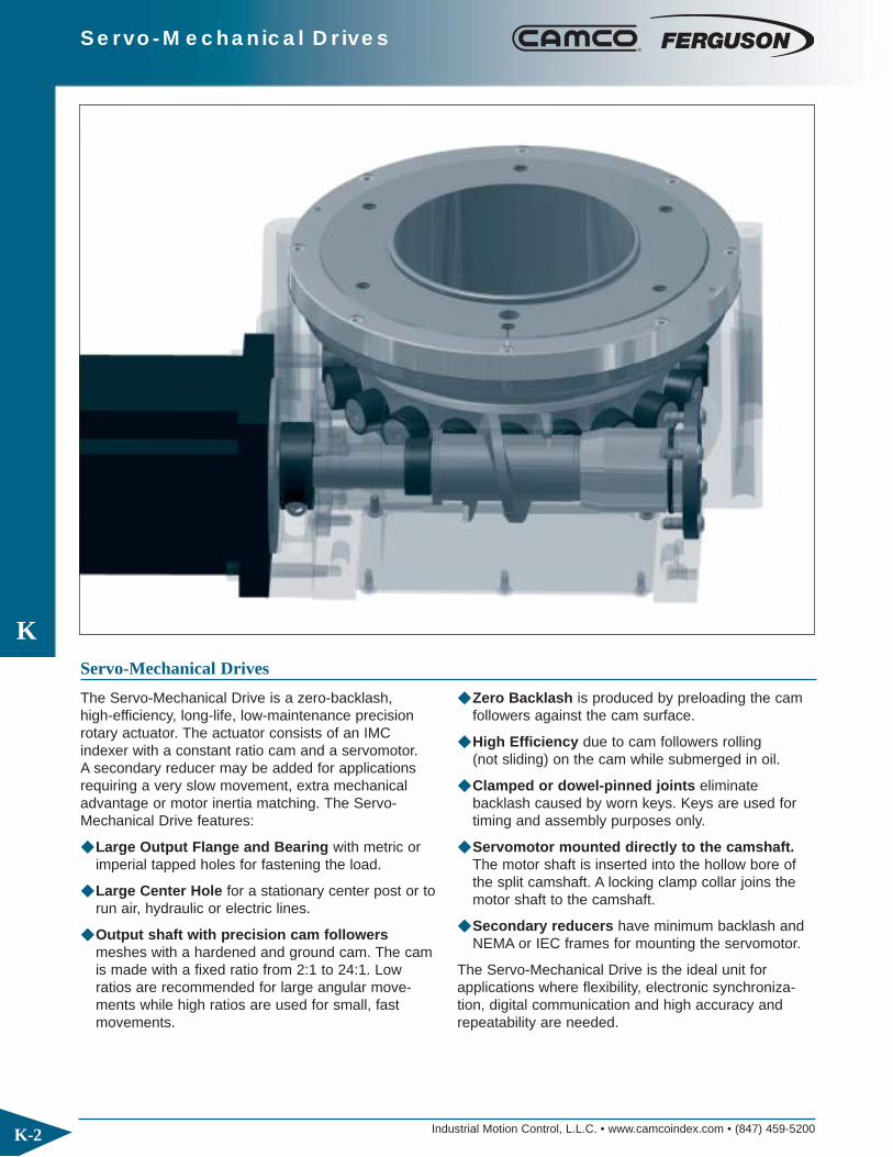
Industrial Motion Control, L.L.C. • www.camcoindex.com • (847) 459-5200
K
K-2
Servo-Mechanical Drives
The Servo-Mechanical Drive is a zero-backlash, high-efficiency, long-life, low-maintenance precisionrotary actuator. The actuator consists of an IMCindexer with a constant ratio cam and a servomotor. A secondary reducer may be added for applicationsrequiring a very slow movement, extra mechanicaladvantage or motor inertia matching. The Servo-Mechanical Drive features:
◆ Large Output Flange and Bearing with metric or imperial tapped holes for fastening the load.
◆ Large Center Hole for a stationary center post or torun air, hydraulic or electric lines.
◆ Output shaft with precision cam followersmeshes with a hardened and ground cam. The cam is made with a fixed ratio from 2:1 to 24:1. Low ratios are recommended for large angular move-ments while high ratios are used for small, fast movements.
◆ Zero Backlash is produced by preloading the cam followers against the cam surface.
◆ High Efficiency due to cam followers rolling(not sliding) on the cam while submerged in oil.
◆ Clamped or dowel-pinned joints eliminatebacklash caused by worn keys. Keys are used for timing and assembly purposes only.
◆ Servomotor mounted directly to the camshaft.The motor shaft is inserted into the hollow bore of the split camshaft. A locking clamp collar joins the motor shaft to the camshaft.
◆ Secondary reducers have minimum backlash and NEMA or IEC frames for mounting the servomotor.
The Servo-Mechanical Drive is the ideal unit for applications where flexibility, electronic synchroniza-tion, digital communication and high accuracy andrepeatability are needed.
Servo-Mechanical Drives

Industrial Motion Control, L.L.C. • www.camcoindex.com • (847) 459-5200 K-3
Servo-Mechanical Drives
Flex-I-Dex
K
The Flex-i-Dex is ideal for light duty applications orshort, fast movements. The complete Flex-i-Dexpackage includes:
◆ Flex-i-Dex constant-lead (constant ratio) drive with either a large flange output or a shaft output.
◆ Control Techniques Servo Motor, Uni-Drive SPcontroller, power and logic cables and Power Tools software.
R
4X R
6X Q
NM
K
L
H
G
THRUAB
D
E
F
JJS
TSQUARE
C
Flex-i-Dex withDial/Flange Output
Dimensions – Flex-i-Dex with Dial/Flange Ouput
S J J
SQUARET
G
H
E
F
N
P
DC
A
RU
MM
B
L
4X R
K
4X Q
KWY
Flex-i-Dex with Shaft Output
Model A B C D E F G H J K L M N Q R S TDSD-102 115 176 206 105 90 45 147 102 87.5 90 210 156 110 M8x16 10.7 280 89DSD-150 170 270 310 145 130 65 212 150 125 140 310 215 160 M10x20 12.7 287 115
Model A B C D E F G H J K L M N Q R S T UDSD-102S 35 h7 206 65 95 90 45 157 102 87.5 90 210 75 120 10.7 10.7 280 89 10x5 (N9)DSD-150S 45 h6 310 85 135 130 65 227 150 125 140 310 105 160 12.7 12.7 387 115 14x5.5 (N9)
Dimensions – Flex-i-Dex with Shaft Ouput
All dimensions are subject to change. For actual dimensions, please request the current drawing from IMC.
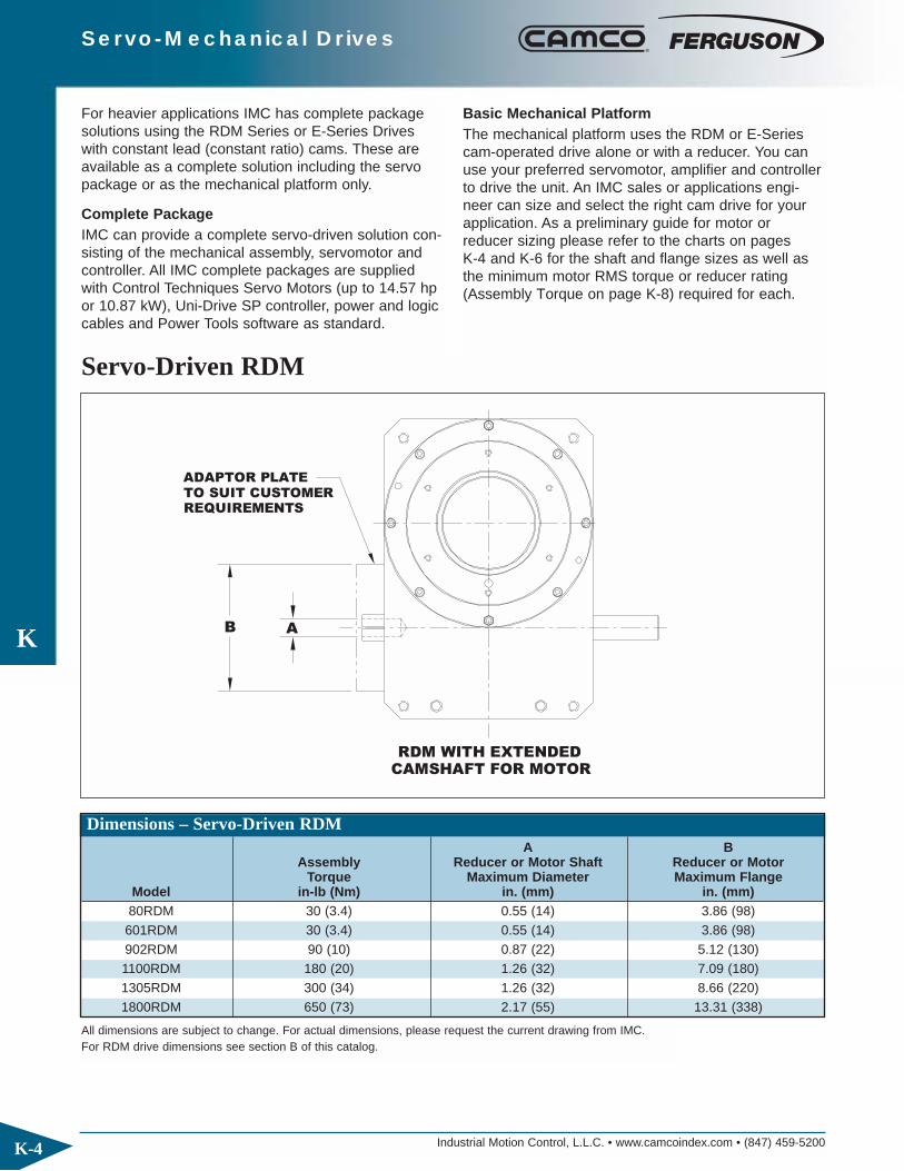
Industrial Motion Control, L.L.C. • www.camcoindex.com • (847) 459-5200
K
K-4
Servo-Mechanical Drives
For heavier applications IMC has complete packagesolutions using the RDM Series or E-Series Driveswith constant lead (constant ratio) cams. These areavailable as a complete solution including the servopackage or as the mechanical platform only.
Complete PackageIMC can provide a complete servo-driven solution con-sisting of the mechanical assembly, servomotor andcontroller. All IMC complete packages are suppliedwith Control Techniques Servo Motors (up to 14.57 hpor 10.87 kW), Uni-Drive SP controller, power and logiccables and Power Tools software as standard.
Basic Mechanical Platform The mechanical platform uses the RDM or E-Seriescam-operated drive alone or with a reducer. You canuse your preferred servomotor, amplifier and controllerto drive the unit. An IMC sales or applications engi-neer can size and select the right cam drive for yourapplication. As a preliminary guide for motor orreducer sizing please refer to the charts on pages K-4 and K-6 for the shaft and flange sizes as well asthe minimum motor RMS torque or reducer rating(Assembly Torque on page K-8) required for each.
Servo-Driven RDM
CAMSHAFT FOR MOTORRDM WITH EXTENDED
B A
ADAPTOR PLATETO SUIT CUSTOMERREQUIREMENTS
Dimensions – Servo-Driven RDM
All dimensions are subject to change. For actual dimensions, please request the current drawing from IMC.For RDM drive dimensions see section B of this catalog.
A BAssembly Reducer or Motor Shaft Reducer or Motor
Torque Maximum Diameter Maximum FlangeModel in-lb (Nm) in. (mm) in. (mm)80RDM 30 (3.4) 0.55 (14) 3.86 (98)601RDM 30 (3.4) 0.55 (14) 3.86 (98)902RDM 90 (10) 0.87 (22) 5.12 (130)1100RDM 180 (20) 1.26 (32) 7.09 (180)1305RDM 300 (34) 1.26 (32) 8.66 (220)1800RDM 650 (73) 2.17 (55) 13.31 (338)

Industrial Motion Control, L.L.C. • www.camcoindex.com • (847) 459-5200
K
K-5
Servo-Mechanical Drives
RDM WITH RIGHT ANGLE PLANETARYREDUCER (NO MOTOR)
RDM WITH INLINE PLANETARY REDUCER (NO MOTOR)
RDM WITH MOTORDIRECTLY CONNECTED

Industrial Motion Control, L.L.C. • www.camcoindex.com • (847) 459-5200
K
K-6
Servo-Mechanical Drives
Servo-Driven Heavy-Duty E-SeriesFor heavy-duty applications, the E-Series drive can be supplied with a constant lead (constant ratio) cam, withor without the servo package.
E-SERIES WITH EXTENDEDCAMSHAFT FOR MOTOR
REQUIREMENTS
B A
ADAPTOR PLATETO SUIT CUSTOMER
Dimensions – Servo-Driven Heavy-Duty E-Series
All dimensions are subject to change. For actual dimensions, please request the current drawing from IMC.For E-Series drive dimensions see section G of this catalog.
A BAssembly Reducer or Motor Shaft Reducer or Motor
Torque Maximum Diameter Maximum FlangeModel in-lb (Nm) in. (mm) in. (mm)750E 650 (73.45) 2.17 (55) 7.36 (187)950E 650 (73.45) 2.17 (55) 6.61 (168)1150E 1100 (124.29) 2.95 (75) 8.15 (207)1550E 1550 (175.14) 2.95 (75) 7.24 (184)2050E 2000 (225.99) 3.35 (85) 12.99 (330)

Industrial Motion Control, L.L.C. • www.camcoindex.com • (847) 459-5200
K
K-7
Servo-Mechanical Drives
E-SERIES WITH RIGHT ANGLEPLANETARY REDUCER (NO MOTOR)
E-SERIES WITH INLINEPLANETARY REDUCER (NO MOTOR)
E-SERIES WITH MOTORDIRECTLY CONNECTED
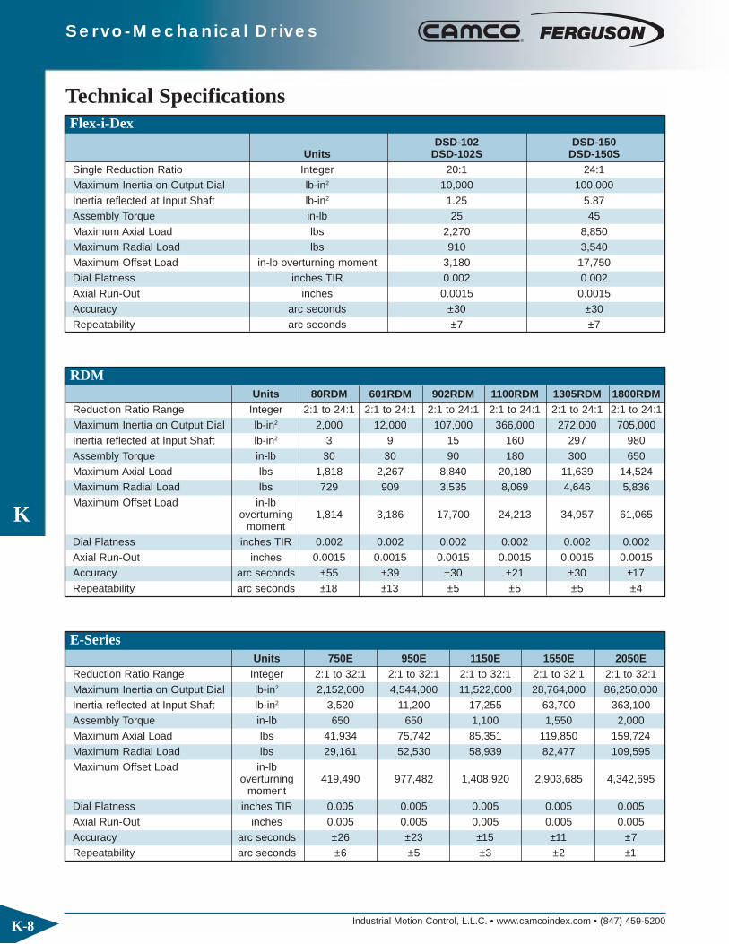
Industrial Motion Control, L.L.C. • www.camcoindex.com • (847) 459-5200
K
K-8
Servo-Mechanical Drives
Technical SpecificationsFlex-i-Dex
DSD-102 DSD-150Units DSD-102S DSD-150S
Single Reduction Ratio Integer 20:1 24:1Maximum Inertia on Output Dial lb-in2 10,000 100,000Inertia reflected at Input Shaft lb-in2 1.25 5.87Assembly Torque in-lb 25 45Maximum Axial Load lbs 2,270 8,850Maximum Radial Load lbs 910 3,540Maximum Offset Load in-lb overturning moment 3,180 17,750Dial Flatness inches TIR 0.002 0.002Axial Run-Out inches 0.0015 0.0015Accuracy arc seconds ±30 ±30Repeatability arc seconds ±7 ±7
RDMUnits 80RDM 601RDM 902RDM 1100RDM 1305RDM 1800RDM
Reduction Ratio Range Integer 2:1 to 24:1 2:1 to 24:1 2:1 to 24:1 2:1 to 24:1 2:1 to 24:1 2:1 to 24:1Maximum Inertia on Output Dial lb-in2 2,000 12,000 107,000 366,000 272,000 705,000Inertia reflected at Input Shaft lb-in2 3 9 15 160 297 980Assembly Torque in-lb 30 30 90 180 300 650Maximum Axial Load lbs 1,818 2,267 8,840 20,180 11,639 14,524Maximum Radial Load lbs 729 909 3,535 8,069 4,646 5,836Maximum Offset Load in-lb
overturning 1,814 3,186 17,700 24,213 34,957 61,065moment
Dial Flatness inches TIR 0.002 0.002 0.002 0.002 0.002 0.002Axial Run-Out inches 0.0015 0.0015 0.0015 0.0015 0.0015 0.0015Accuracy arc seconds ±55 ±39 ±30 ±21 ±30 ±17Repeatability arc seconds ±18 ±13 ±5 ±5 ±5 ±4
E-SeriesUnits 750E 950E 1150E 1550E 2050E
Reduction Ratio Range Integer 2:1 to 32:1 2:1 to 32:1 2:1 to 32:1 2:1 to 32:1 2:1 to 32:1Maximum Inertia on Output Dial lb-in2 2,152,000 4,544,000 11,522,000 28,764,000 86,250,000Inertia reflected at Input Shaft lb-in2 3,520 11,200 17,255 63,700 363,100Assembly Torque in-lb 650 650 1,100 1,550 2,000Maximum Axial Load lbs 41,934 75,742 85,351 119,850 159,724Maximum Radial Load lbs 29,161 52,530 58,939 82,477 109,595Maximum Offset Load in-lb
overturning 419,490 977,482 1,408,920 2,903,685 4,342,695moment
Dial Flatness inches TIR 0.005 0.005 0.005 0.005 0.005Axial Run-Out inches 0.005 0.005 0.005 0.005 0.005Accuracy arc seconds ±26 ±23 ±15 ±11 ±7Repeatability arc seconds ±6 ±5 ±3 ±2 ±1

IMC offers a variety of accessories to complete yourautomation package.
◆ AC Inverter Duty Motors and Drives
◆ DC Motors and Motor Controls
◆ Digi-Dog Electronic Limit Switch
◆ Camtronics Rotary Limit Switch
◆ Clutch-Brakes
◆ Spare Parts

Industrial Motion Control, L.L.C. • www.camcoindex.com • (847) 459-5200
L
L-2
Accessories
AC Drives
The IMC AC Inverter Drive System is a high performance, cost effective alternative to DC drives,clutch-brakes and brake motors. Positioning isachieved using a photoeye with a reaction time of less
than 1 ms. Once stopping position is set, the drive willautomatically adjust for any speed differences with anextremely low margin of error. The special algorithmsused in the drive make it the most accurate anddependable indexing drive for your applications. AC Drive features include:
◆ Up to 60 cycles per minute (1/3 and 1 hp)
◆ Sophisticated inverter designed for indexing applications
◆ Adjustable set speed with fixed stopping position
◆ Tight, repeatable accuracy
◆ Simple, easy to use programming
◆ Bi-directional
◆ PLC/PC communication
◆ CE, UL conformance
◆ Uses standard 3 phase AC motors or low profile,high power motors designed for indexing applications
◆ IP20 Enclosure
◆ 230V single phase or 460V 3 phase
DC Drives
IMC DC Motors and Drives offer efficient, low-costcycle-on-demand control for up to 30 cycles perminute. These motors and controls have variablespeed capability for control of indexing rates and automated motor cycling for variable dwell periods.IMC’s Varipak DC drive includes:
◆ Current Limiting protects the drive system fromoverloads and provides smooth acceleration of highinertia loads.
◆ NEMA 12 Enclosure is removable for chassismounting
◆ External Control Terminal Strip allows for CycleStart, Cycle Stop and Jog from Relay-PLC interface.
◆ Line Regulation – the control is unaffected by voltage fluctuations. Set speed will vary less than1%, ensuring consistent drive system output.
◆ Transient Protection of power components againstline voltage spikes with voltage clamping MOV’sand RC networks.
◆ Load Regulation – 5% of base speed accuracywith armature feedback. Results in consistentmachine output regardless of load conditions.
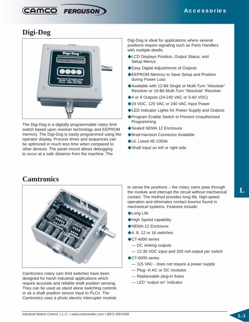
Industrial Motion Control, L.L.C. • www.camcoindex.com • (847) 459-5200
L
L-3
Accessories
Digi-Dog
The Digi-Dog is a digitally programmable rotary limitswitch based upon resolver technology and EEPROMmemory. The Digi-Dog is easily programmed using theoperator display. Process times and sequences canbe optimized in much less time when compared toother devices. The panel mount allows debugging to occur at a safe distance from the machine. The
Digi-Dog is ideal for applications where several positions require signaling such as Parts Handlerswith multiple dwells.
◆ LCD Displays Position, Output Status, and Setup Menus
◆ Easy Digital Adjustments of Outputs
◆ EEPROM Memory to Save Setup and Position during Power Loss
◆ Available with 12-Bit Single or Multi-Turn “Absolute”Resolver or 16-Bit Multi-Turn “Absolute” Resolver
◆ 4 or 8 Outputs (24-240 VAC or 5-60 VDC)
◆ 24 VDC, 120 VAC or 240 VAC Input Power
◆ LED Indicator Lights for Power Supply and Outputs
◆ Program Enable Switch to Prevent UnauthorizedProgramming
◆ Sealed NEMA 12 Enclosure
◆ Brad-Harrison Connector Available
◆ UL Listed #E-23556
◆ Shaft input on left or right side
Camtronics
Camtronics rotary cam limit switches have beendesigned for harsh industrial applications whichrequire accurate and reliable shaft position sensing.They can be used as stand alone switching controls or as a shaft position sensor input to PLCs. TheCamtronics uses a photo electric interrupter module
to sense the positions – the rotary cams pass throughthe module and interrupt the circuit without mechanicalcontact. The method provides long life, high-speedoperation and eliminates contact bounce found inmechanical systems. Features include:
◆ Long Life
◆ High Speed capability
◆ NEMA-12 Enclosure
◆ 4, 8, 12 or 16 switches
◆ CT-4000 series
— DC sinking outputs
— 12-30 VDC input and 200 mA output per switch
◆ CT-6000 series
— 115 VAC - does not require a power supply
— Plug- in AC or DC modules
— Replaceable plug-in fuses
— LED “output on” indicator
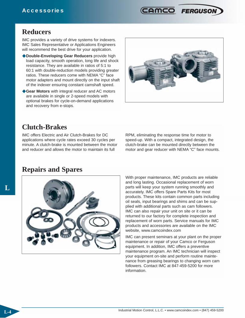
Industrial Motion Control, L.L.C. • www.camcoindex.com • (847) 459-5200
L
L-4
Accessories
ReducersIMC provides a variety of drive systems for indexers.IMC Sales Representative or Applications Engineerswill recommend the best drive for your application.
◆ Double-Enveloping Gear Reducers provide highload capacity, smooth operation, long life and shockresistance. They are available in ratios of 5:1 to60:1 with double-reduction models providing greaterratios. These reducers come with NEMA “C” facemotor adapters and mount directly on the input shaftof the indexer ensuring constant camshaft speed.
◆ Gear Motors with integral reducer and AC motorsare available in single or 2-speed models withoptional brakes for cycle-on-demand applicationsand recovery from e-stops.
Repairs and SparesWith proper maintenance, IMC products are reliableand long lasting. Occasional replacement of wornparts will keep your system running smoothly andaccurately. IMC offers Spare Parts Kits for most products. These kits contain common parts includingoil seals, input bearings and shims and can be sup-plied with additional parts such as cam followers. IMC can also repair your unit on site or it can bereturned to our factory for complete inspection andreplacement of worn parts. Service manuals for IMCproducts and accessories are available on the IMCwebsite, www.camcoindex.com
IMC can present seminars at your plant on the propermaintenance or repair of your Camco or Fergusonequipment. In addition, IMC offers a preventive maintenance program. An IMC technician will inspectyour equipment on-site and perform routine mainte-nance from greasing bearings to changing worn camfollowers. Contact IMC at 847-459-5200 for moreinformation.
Clutch-BrakesIMC offers Electric and Air Clutch-Brakes for DC applications where cycle rates exceed 30 cycles perminute. A clutch-brake is mounted between the motorand reducer and allows the motor to maintain its full
RPM, eliminating the response time for motor tospeed-up. With a compact, integrated design, theclutch-brake can be mounted directly between themotor and gear reducer with NEMA “C” face mounts.

FeaturesIMC’s Torq/Gard overload clutches help protect the entire drive train of your machinery from damage due to excessive torque generated by overloads and jamming. Instant reaction when torque exceeds preset limits provides protection far superior to that of clutchesemploying friction surfaces. Torq/Gard features include:
◆ Modular Design: one unit for direct drive, chain drive or other power transmission options
◆ Universal Mounting: eliminates special bore requirements
◆ Single Position, Automatic Reset
◆ Reversible
◆ Torque Repeatability

Industrial Motion Control, L.L.C. • www.camcoindex.com • (847) 459-5200
M
M-2
TORQ/GARD™ Overload Clutches
Torq/Gard™ Features
SEALED FOR LIFE Gasket andO-ring sealed body, packed withhigh-performance, moistureresistant grease for outdoor andwash-down applications.
FLAT WIRE HELICALSPRING Maintainstorque limit within narrow tolerance.
HEX-SOCKET HEADTORQUE CONTROLPermits quick, easyadjustment of torquelimit.
DRILLED AND TAPPEDMOUNTING LUGSRegistered for platesprocket or other outputoptions.
MAXIMUM SHAFT BOREArranged to accommodatestock shaft bushings.
FORGED STEEL HUBHeat-treated with oversized bore.
PRECISION NEEDLEBEARINGS for yearsof wear-free service atlever arm pivot points.
RUGGED ANTI-FRICTIONCAM FOLLOWERHardened, precision-ground tool steel.
ALUMINUM HOUSING WITHINTERNATIONAL ORANGEFINISH.
HEAVY-DUTY NEEDLEBEARINGS for greateroverhung load capacity.
ALLOY STEELFORGED CAMOne piece hard-ened steel camand hub.

Industrial Motion Control, L.L.C. • www.camcoindex.com • (847) 459-5200
M
M-3
TORQ/GARD™ Overload Clutches
Torq/Gard overload clutches are available in sevensizes with capacities trip torques from 13 in-lbs to8000 in-lbs.
Torq/Gard Clutches may be sized using the Speed-Horsepower Chart, the Speed-Torque Chart and theseformulas:
Torque (in-lb) = Horsepower (hp) x 63025 / RPM
Horsepower (hp) = Torque (in-lbs) x RPM / 63025
Tripping Torque (in-lbs) = Operating Torque x Service Factor
Torq/Gard™ Sizing and Selection
RPM 1/4 1/2 3/4 1 1.5 2 3 5 7.5 10 15 20 30 35
20
40
60
80
100
200
300
400
500
600
700
800
900
40
TG60
TG200
TG400TG800
HORSEPOWER
TG 3 TG 6
TG 20
800
900
1000
1200
1400
1600
1800
80
100
200
300
400
500
600
700
RPM
20
40
60
.007 .013 .027 .050 .090 .15 .25 .50 1.00 2.00 3.00 5.00
HORSEPOWER
SPEED/HORSEPOWER CHART
SPEED/TORQUE CHART
Trip Torque Maximum(in-lbs) HP RPM Weight Inertia Bore Dia.
Model Min. Max. Max Max (lbs) (lb-in) (in)
TG3 13.3 32.7 1.5 1800 1.32 1.45 0.500
TG6 23 56.6 2.5 1800 1.32 1.45 0.500
TG20 56.6 204 4 1500 2.42 5.72 0.787
TG60 200 600 8.5 900 5.5 10 1 1/4
TG200 600 2000 21.5 680 12 46 1 15/16
TG400 2000 4000 22.2 350 38 455 2 7/16
TG800 4000 8000 44.4 350 38 455 2 7/16

Industrial Motion Control, L.L.C. • www.camcoindex.com • (847) 459-5200
M
M-4
TORQ/GARD™ Overload Clutches
Torq/Gard™ Dimensions
L
A
øK
P
TRAVEL @ OVERLOADC DETECTOR
øI
G(MAX.)
øH
F
D
B
øJ
øN
37. 5°
3 x M HOLES
EQUALLY SPACED
E
R KEYWAY
All dimensions are subject to change. For actual dimensions, please request the current drawing from IMC.
Model A B C D E F G H I J K L M N P R
TG3 2.36 2.31 0.16 1.89 0.27 1.62 0.500 0.87 1.187 1.97 3.15 0.32 #8-32 1.575 0.12 0.125
TG6 2.36 2.31 0.16 1.89 0.27 1.62 0.500 0.87 1.187 1.97 3.15 0.32 #8-32 1.575 0.12 0.125
TG20 2.76 2.72 0.16 2.24 0.36 1.94 0.787 1.18 1.563 2.36 3.94 0.39 #10-24 1.965 0.12 0.188
TG60 3.50 3.28 0.25 2.67 0.49 1.97 1.250 1.88 2.375 3.38 5.25 0.56 .250-20 2.875 0.19 0.250
TG200 4.31 4.04 0.25 3.36 0.56 2.80 1.938 2.75 3.250 5.00 7.00 0.75 .375-16 4.500 0.19 0.500
TG400 6.19 6.14 0.31 5.17 0.62 3.80 2.438 3.50 4.500 7.50 10.75 1.12 .500-13 6.500 0.19 0.625
TG800 6.19 6.14 0.31 5.17 0.62 3.80 2.438 3.50 4.500 7.50 10.75 1.12 .500-13 6.500 0.19 0.625
TORQ/GARD DIMENSIONS
The Torq/Gard should be used on the low speed sideof a speed reducer in several ways:
◆ Direct Drive: The Torq/Gard can be mounting on thespeed reducer output (low speed) shaft and directlyconnected to the driven machine using a BrowningEver-Flex half coupling and the Universal AdapterPlate.
◆ Chain Drive – Mounted on Speed Reducer Output:Mounting the Torq/Gard on the output of the gearmotor or speed reducer with a roller chain con-nection to the driven machine provides the mosteconomical clutch assembly. The Torq/Gard isdesigned to protect the weakest link in the drive system.
◆ Chain Drive – Mounted on Driven Machine:Mounting the Torq/Gard on the driven machine andpowered through a chain and sprocket drive tendsto absorb peak starting torques.
◆ The Torq/Gard should never be used on the high speed side of a reducer. Clutch sensitivitybecomes a function of the reducer’s gear ratio. As an example, when used with a 100:1 reducer, a 100 in-lb torque variation on the output side of thereducer will reflect only a 1 in-lb change on the inputside. Do not exceed the maximum RPM shown inthe Torq/Gard selection tables.
Torq/Gard™ Application Considerations

Industrial Motion Control provides expertise tocustomize Camco and Ferguson products foryour applications including:
◆ Custom Cam manufacturing in a wide varietyof sizes, materials and configurations
◆ Custom Cam design engineering
◆ Customization of IMC products or integrationof IMC products with each other
◆ Custom Components: Cam and FollowersWheel supplied “without the box”
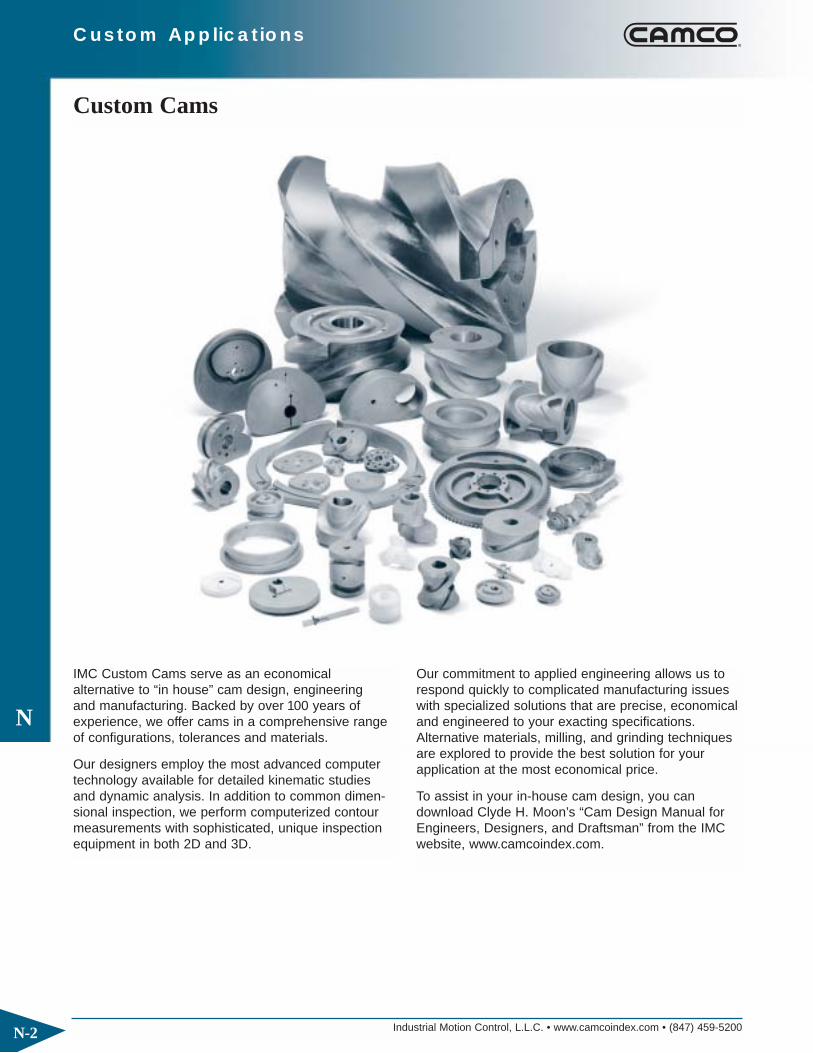
Industrial Motion Control, L.L.C. • www.camcoindex.com • (847) 459-5200
N
N-2
Custom Applications
IMC Custom Cams serve as an economical alternative to “in house” cam design, engineering and manufacturing. Backed by over 100 years of experience, we offer cams in a comprehensive rangeof configurations, tolerances and materials.
Our designers employ the most advanced computertechnology available for detailed kinematic studies and dynamic analysis. In addition to common dimen-sional inspection, we perform computerized contourmeasurements with sophisticated, unique inspectionequipment in both 2D and 3D.
Our commitment to applied engineering allows us torespond quickly to complicated manufacturing issueswith specialized solutions that are precise, economicaland engineered to your exacting specifications.Alternative materials, milling, and grinding techniquesare explored to provide the best solution for yourapplication at the most economical price.
To assist in your in-house cam design, you can download Clyde H. Moon’s “Cam Design Manual forEngineers, Designers, and Draftsman” from the IMCwebsite, www.camcoindex.com.
Custom Cams

Industrial Motion Control, L.L.C. • www.camcoindex.com • (847) 459-5200
N
N-3
Custom Applications
Custom Cams are available in a variety of styles:
Plate CamsPopular, economical design used in low speedapplications.
Globoidal CamsComplex, tapered rib globoidal cams, commonlyknown as roller gear cams, are the heart of IMC’sindexers. Controlled follower preloads increase follower life, speeds and accuracy for the ultimatesolution in motion control.
Face-Grooved CamsMedium speed cams using a groove slightly larger than the follower diameter providing minimal running clearance and reduced backlash.
Conjugate CamsDual cams controlling preloaded followers which provide higher speed capabilities and better accuracy.
Barrel CamsCylindrical cams which can be provided as an endcam, grooved type with minimal follower clearanceor as a ribbed type utilizing preloaded followers forincreased life and accuracy.

Industrial Motion Control, L.L.C. • www.camcoindex.com • (847) 459-5200
N
N-4
Custom Applications
Custom MachineryIMC will work with your engineers to customize ourproducts to your application including:
◆ Index Drives with Custom Motions
— Oscillating
— Matched Velocity
◆ Custom Dimensions
— Extended Shafts
— Special Mounting Hole Patterns
◆ Integration of IMC products such as Parts Handlerscombined with Conveyor on a common base
◆ Custom Components: Cam and Follower wheel supplied “without the box”

PRECISELY POSITIONING OUR CUSTOMERS FOR PRODUCTIVITY.Workholding
• Widest variety of workholding products• High durability and reliability• Flexible solutions for all applications• Custom products for unique requirements
Automation• Broad range of engineered automation products • Complementary products for modular integration • Unmatched accuracy, reliability and performance • Unparalleled global sales, service and engineering support
© Copyright, 2008 DE-STA-CO. All rights for layout, photos and text rest with the publisher DE-STA-CO. All photomechanical or other reproductions only with our express permission. All sales are based on our terms and conditions of sale, delivery and payment.
Precisely positioning our customers for productivity.
NORTH AMERICADE-STA-CO HeadquartersAuburn Hills, MichiganTel: 1.248.836.6700Marketing: [email protected]
Auburn Hills, MichiganTel: 1.888.DESTACOCustomer Service: [email protected]
Wheeling, IllinoisTel: 1.800.645.5207Customer Service: [email protected]
Charlevoix, MichiganTel: 1.888.DESTACO Customer Service: [email protected]
Red Wing, MN (Central Research Laboratories) Tel: 651.385.2142 Customer Service: [email protected]
SOUTH AMERICABrazilTel: 0800-124070Customer Service: [email protected]
ASIAThailandTel: +66-2-326-0812Customer Service: [email protected]
ChinaTel: +86-21-5423-4435Customer Service: [email protected]
IndiaTel: +91 80 41123421-426Customer Service: [email protected]
EUROPEGermanyTel: +49-6171-705-0Customer Service: [email protected]
FranceTel: +33-1-3996-5000Customer Service: [email protected]
UKTel: +44-1902-797980Customer Service: [email protected]
SpainTel: +34-936361680Customer Service: [email protected]
NetherlandsTel: +31-297285332Customer Service: [email protected]
DE-STA-CO GLOBAL LOCATIONS
CAMCO Products1444 South Wolf Road Wheeling, IL 60090Phone: 1.847.459.5200 Fax: 1.847.459.3064Email: [email protected]
0000-04/08