Embed Size (px)
DESCRIPTION
Citation preview
Cadence SKILL PCELL
Tutorial © TYLEE RFVLSI LAB, NCTU
Cadence SKILL PCELL
Tutorial
Tao-Yi Lee
Advisor: Dr. Yu-Jiu Wang
RFVLSI LAB, NCTU
2014/4/18 1
Cadence SKILL PCELL
Tutorial © TYLEE RFVLSI LAB, NCTU
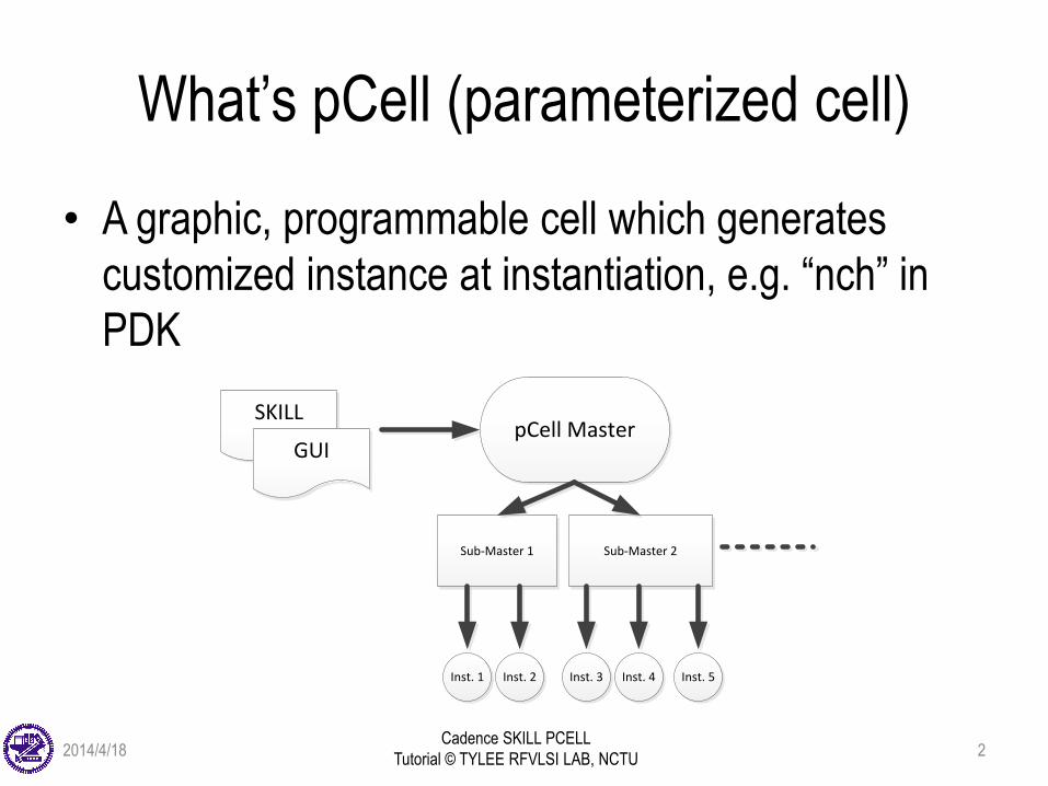
What’s pCell (parameterized cell)
• A graphic, programmable cell which generates
customized instance at instantiation, e.g. “nch” in
PDK
SKILLpCell Master
GUI
Sub-Master 1 Sub-Master 2
Inst. 1 Inst. 2 Inst. 3 Inst. 4 Inst. 5
2014/4/18 2
Cadence SKILL PCELL
Tutorial © TYLEE RFVLSI LAB, NCTU
What’s pCell (parameterized cell)
• pCell Master
– the pCell you create; combination of the graphic layout
and the parameters assigned to it
– stored in the form of a SKILL procedure
– all changes are made onto pCell master instead of
instance
2014/4/18 3
Cadence SKILL PCELL
Tutorial © TYLEE RFVLSI LAB, NCTU
Advantages of pCell
• Speed up entering layout data
– eliminating the need to create duplicate versions of the same functional part
• Eliminate errors
• Eliminate the need to explode levels of hierarchy
– when you want to change a small detail of a design
• Save disk space
– creating a library of cells for similar parts that are all linked to the same source
2014/4/18 4
Cadence SKILL PCELL
Tutorial © TYLEE RFVLSI LAB, NCTU
Creating a Pcell
• Graphically
– using the commands in the PCell menu.
• Textually
– in an ASCII file using SKILL language commands.
– we will only use this method
– Easier creation of complex designs
– Easier maintenance of Pcell code: RCS and Makefile
– Process portability and independence
2014/4/18 5
Cadence SKILL PCELL
Tutorial © TYLEE RFVLSI LAB, NCTU
Safety Rules for Creating SKILL Pcells
• Pcell code should not react to, interact with, or
be dependent on an environment
– Independent of the environment in which they are
created
– Independent of the environments in which you or
someone else might want to use them.
2014/4/18 6
Cadence SKILL PCELL
Tutorial © TYLEE RFVLSI LAB, NCTU
Physical Limits for SKILL Functions
• Total number of required arguments is less than 255
• Total number of keyword/optional arguments is less
than 255
• Total number of local variables in a let is less than
255
• Maximum number of arguments a function can
receive is less than 32 Kb
• Maximum size of code vector is less than 32 Kb
2014/4/18 7
Cadence SKILL PCELL
Tutorial © TYLEE RFVLSI LAB, NCTU
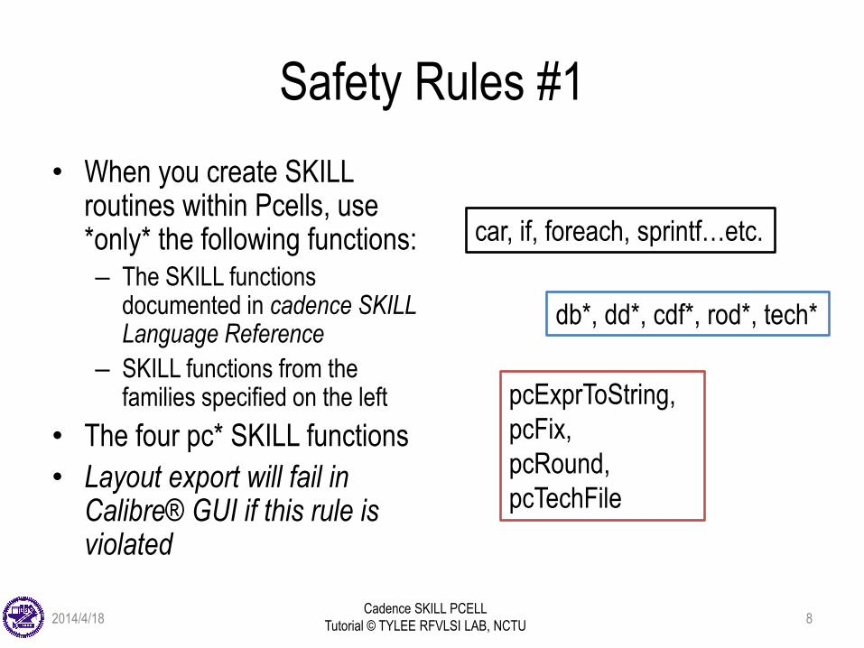
Safety Rules #1
• When you create SKILL routines within Pcells, use *only* the following functions: – The SKILL functions
documented in cadence SKILL Language Reference
– SKILL functions from the families specified on the left
• The four pc* SKILL functions
• Layout export will fail in Calibre® GUI if this rule is violated
car, if, foreach, sprintf…etc.
db*, dd*, cdf*, rod*, tech*
pcExprToString,
pcFix,
pcRound,
pcTechFile
2014/4/18 8
Cadence SKILL PCELL
Tutorial © TYLEE RFVLSI LAB, NCTU
Safety Rules #2
• Do not generate messages; message output is
interpreted as an error
– Use fprintf(stdout "myVariable = %L \n" myVariable )
instead
– If you use print, choose Verify -> Markers -> Explain. To
retrieve message
2014/4/18 9
Cadence SKILL PCELL
Tutorial © TYLEE RFVLSI LAB, NCTU
Safety Rules #3
• If you need to drive external programs to calculate shapes, do it with CDF callback procedures to save the resulting list of coordinate pairs in a string, and then pass the string as input to a Pcell
• This method has the advantage that the external program needs to be called only once per instance, not each time the design is opened.– To learn more about callback procedures, refer to Virtuoso
Parameterized Cell Reference, “Using the Component Description Format”
2014/4/18 10
Cadence SKILL PCELL
Tutorial © TYLEE RFVLSI LAB, NCTU
Safety Rules #4
• Enclosing the Body of Code in a let or prog for local
variables
– To use local variables, *be sure* to enclose pCell body
(anything inside pcDefinePCell) in a let or prog statement.
– Define all variables used in the Pcell code at the beginning
of the let or prog statement.
– Defining variables as part of a let or prog prevents conflicts
with variables used by the Pcell compiler.
– Using let gives faster performance than prog; prog allows
multiple exits while let exits only at its end.
2014/4/18 11
Cadence SKILL PCELL
Tutorial © TYLEE RFVLSI LAB, NCTU
Safety Rules #5, 6, and 7
• Do not prompt the user for input
• Do not run any external program that starts another
process
• Do not load, read, or write to files in the UNIX file
system
2014/4/18 12
Cadence SKILL PCELL
Tutorial © TYLEE RFVLSI LAB, NCTU
The pcDefinePCell Function
& Complilation of pCell
• Each call to pcDefinePCell creates one Pcell master cellview.
• You can create one source code file for each Pcellor define several Pcells in one file.
• To compile:
– use load(“filename”)
– Note that “filename” is a string so it should be enclosed by double quotes
– No whitespace between “load” and “(”
2014/4/18 13
Cadence SKILL PCELL
Tutorial © TYLEE RFVLSI LAB, NCTU
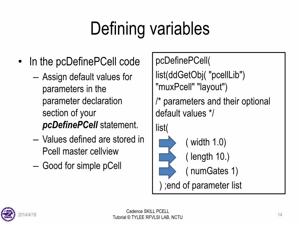
Defining variables
• In the pcDefinePCell code
– Assign default values for
parameters in the
parameter declaration
section of your
pcDefinePCell statement.
– Values defined are stored in
Pcell master cellview
– Good for simple pCell
pcDefinePCell(
list(ddGetObj( "pcellLib")
"muxPcell" "layout")
/* parameters and their optional
default values */
list(
( width 1.0)
( length 10.)
( numGates 1)
) ;end of parameter list
2014/4/18 14
Cadence SKILL PCELL
Tutorial © TYLEE RFVLSI LAB, NCTU
Defining variables (cont’d)
• Using CDF (Component Description Format)
– CDFs can be set upon a cell or for a whole library.
– CDFs defined for a cell apply to all cellviews; for
example, to parameters shared by schematic and layout
cellviews. CDFs defined for a library apply to all cells in
the library.
– Good for complex pCell
– Parameters and default values must agree with their
corresponding ones in “pcDefinePCell”
2014/4/18 15
Cadence SKILL PCELL
Tutorial © TYLEE RFVLSI LAB, NCTU
Defining variables (cont’d)
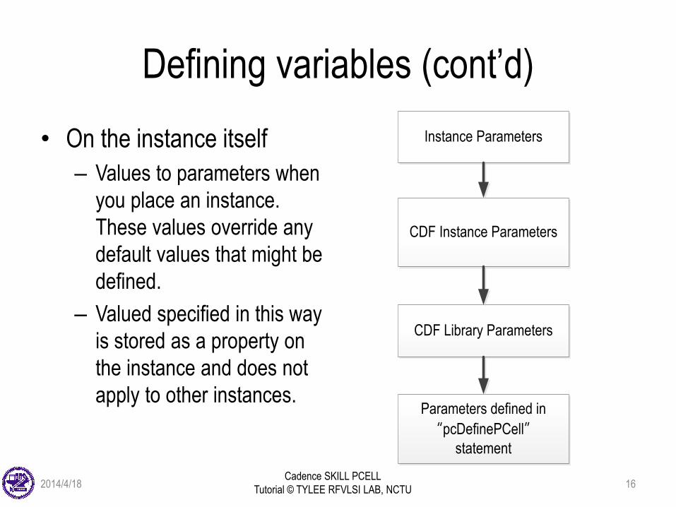
• On the instance itself
– Values to parameters when
you place an instance.
These values override any
default values that might be
defined.
– Valued specified in this way
is stored as a property on
the instance and does not
apply to other instances.
Instance Parameters
CDF Instance Parameters
CDF Library Parameters
Parameters defined in
“pcDefinePCell”statement
2014/4/18 16
Cadence SKILL PCELL
Tutorial © TYLEE RFVLSI LAB, NCTU
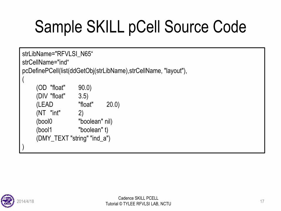
Sample SKILL pCell Source Code
strLibName="RFVLSI_N65“
strCellName="ind“
pcDefinePCell(list(ddGetObj(strLibName),strCellName, "layout"),
(
(OD "float" 90.0)
(DIV "float" 3.5)
(LEAD "float" 20.0)
(NT "int" 2)
(bool0 "boolean" nil)
(bool1 "boolean" t)
(DMY_TEXT "string" "ind_a")
)
2014/4/18 17
Cadence SKILL PCELL
Tutorial © TYLEE RFVLSI LAB, NCTU
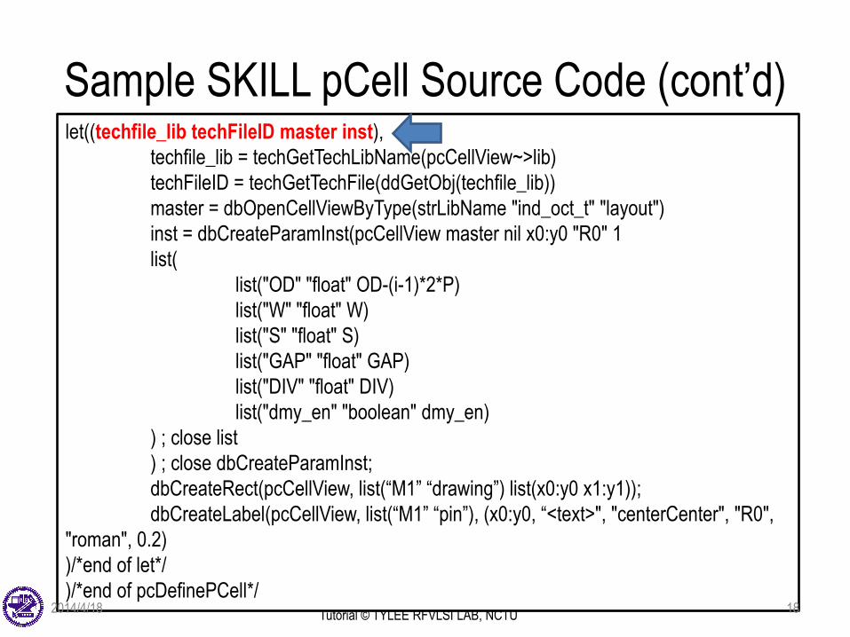
Sample SKILL pCell Source Code (cont’d)let((techfile_lib techFileID master inst),
techfile_lib = techGetTechLibName(pcCellView~>lib)
techFileID = techGetTechFile(ddGetObj(techfile_lib))
master = dbOpenCellViewByType(strLibName "ind_oct_t" "layout")
inst = dbCreateParamInst(pcCellView master nil x0:y0 "R0" 1
list(
list("OD" "float" OD-(i-1)*2*P)
list("W" "float" W)
list("S" "float" S)
list("GAP" "float" GAP)
list("DIV" "float" DIV)
list("dmy_en" "boolean" dmy_en)
) ; close list
) ; close dbCreateParamInst;
dbCreateRect(pcCellView, list(“M1” “drawing”) list(x0:y0 x1:y1));
dbCreateLabel(pcCellView, list(“M1” “pin”), (x0:y0, “<text>", "centerCenter", "R0",
"roman", 0.2)
)/*end of let*/
)/*end of pcDefinePCell*/2014/4/18 18
Cadence SKILL PCELL
Tutorial © TYLEE RFVLSI LAB, NCTU
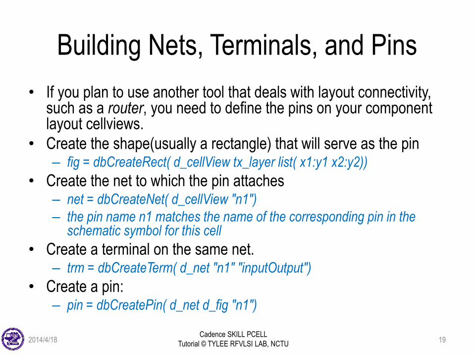
Building Nets, Terminals, and Pins
• If you plan to use another tool that deals with layout connectivity, such as a router, you need to define the pins on your component layout cellviews.
• Create the shape(usually a rectangle) that will serve as the pin – fig = dbCreateRect( d_cellView tx_layer list( x1:y1 x2:y2))
• Create the net to which the pin attaches– net = dbCreateNet( d_cellView "n1")
– the pin name n1 matches the name of the corresponding pin in the schematic symbol for this cell
• Create a terminal on the same net.– trm = dbCreateTerm( d_net "n1" "inputOutput")
• Create a pin:– pin = dbCreatePin( d_net d_fig "n1")
2014/4/18 19
Cadence SKILL PCELL
Tutorial © TYLEE RFVLSI LAB, NCTU
Debugging SKILL Pcells
• Debugging Pcells has historically been a manual task
– Developer would load the SKILL code in CIW and instantiate
a few configurations of the Pcell to verify
– If any issues were found in geometries, the developer would
need to identify the Pcell SKILL code causing these issues.
• In IC6.1.4, a Pcell Integrated Development
Environment (Pcell IDE) has been introduced that
leverages the existing SKILL IDE in DFII
– Reference: Cadence SKILL IDE user guide
2014/4/18 20
Cadence SKILL PCELL
Tutorial © TYLEE RFVLSI LAB, NCTU
Appendix: Function Reference
“dbCreatePath”
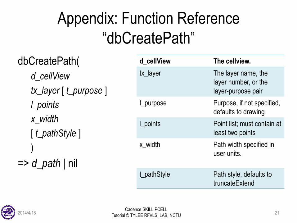
dbCreatePath(
d_cellView
tx_layer [ t_purpose ]
l_points
x_width
[ t_pathStyle ]
)
=> d_path | nil
d_cellView The cellview.
tx_layer The layer name, the
layer number, or the
layer-purpose pair
t_purpose Purpose, if not specified,
defaults to drawing
l_points Point list; must contain at
least two points
x_width Path width specified in
user units.
t_pathStyle Path style, defaults to
truncateExtend
2014/4/18 21
Cadence SKILL PCELL
Tutorial © TYLEE RFVLSI LAB, NCTU
Appendix: Function Reference
“dbCreatePolygon”
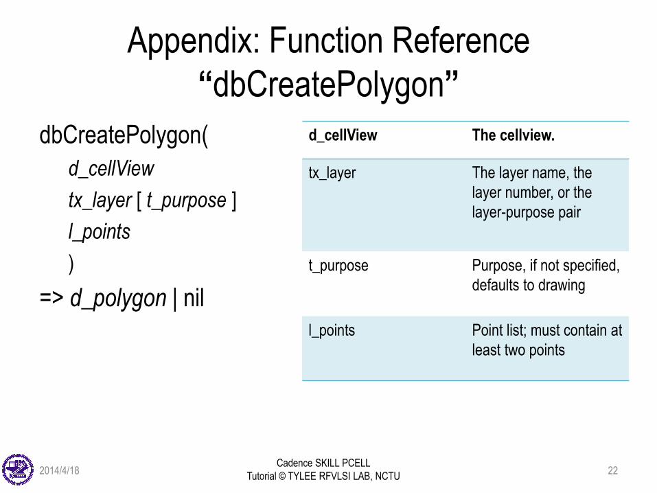
dbCreatePolygon(
d_cellView
tx_layer [ t_purpose ]
l_points
)
=> d_polygon | nil
d_cellView The cellview.
tx_layer The layer name, the
layer number, or the
layer-purpose pair
t_purpose Purpose, if not specified,
defaults to drawing
l_points Point list; must contain at
least two points
2014/4/18 22
Cadence SKILL PCELL
Tutorial © TYLEE RFVLSI LAB, NCTU
Appendix: Function Reference
“dbCreateRect"
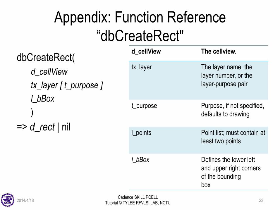
dbCreateRect(
d_cellView
tx_layer [ t_purpose ]
l_bBox
)
=> d_rect | nil
d_cellView The cellview.
tx_layer The layer name, the
layer number, or the
layer-purpose pair
t_purpose Purpose, if not specified,
defaults to drawing
l_points Point list; must contain at
least two points
l_bBox Defines the lower left
and upper right corners
of the bounding
box
2014/4/18 23
Cadence SKILL PCELL
Tutorial © TYLEE RFVLSI LAB, NCTU
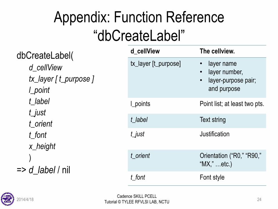
Appendix: Function Reference
“dbCreateLabel”dbCreateLabel(
d_cellView
tx_layer [ t_purpose ]
l_point
t_label
t_just
t_orient
t_font
x_height
)
=> d_label / nil
d_cellView The cellview.
tx_layer [t_purpose] • layer name
• layer number,
• layer-purpose pair;
and purpose
l_points Point list; at least two pts.
t_label Text string
t_just Justification
t_orient Orientation (“R0,” “R90,”
“MX,” …etc.)
t_font Font style
2014/4/18 24
Cadence SKILL PCELL
Tutorial © TYLEE RFVLSI LAB, NCTU
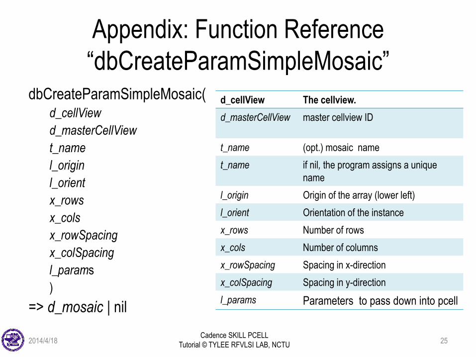
Appendix: Function Reference
“dbCreateParamSimpleMosaic”dbCreateParamSimpleMosaic(
d_cellView
d_masterCellView
t_name
l_origin
l_orient
x_rows
x_cols
x_rowSpacing
x_colSpacing
l_params
)
=> d_mosaic | nil
d_cellView The cellview.
d_masterCellView master cellview ID
t_name (opt.) mosaic name
t_name if nil, the program assigns a unique
name
l_origin Origin of the array (lower left)
l_orient Orientation of the instance
x_rows Number of rows
x_cols Number of columns
x_rowSpacing Spacing in x-direction
x_colSpacing Spacing in y-direction
l_params Parameters to pass down into pcell
2014/4/18 25
Cadence SKILL PCELL
Tutorial © TYLEE RFVLSI LAB, NCTU
References
• Cadence IC6.1.4 manuals:
– Virtuoso Parameterized Cell Reference
– Virtuoso Design Environment SKILL Reference
– Virtuoso Parameterized Cell SKILL Reference
– Sample Parameterized Cells Installation and Reference
2014/4/18 26