Embed Size (px)
Citation preview
ARM: Programmer’s Model
(Chapter 3 in ARM-datasheet)
Ravikumar TiwariAssistant Professor
Dept. of Electronics, [email protected]
www.facebook.com/rravik www.twitter.com/Ravi6096
R.K.Tiwari([email protected])
Processing Operating States
From the programmer’s point of view, the ARM7TDMI can be in one of two states:
ARM state which executes 32-bit, word-aligned ARM instructions.
THUMB state which operates with 16-bit, halfword-aligned THUMB instructions. In this state, the PC uses bit 1 to select between alternate halfwords.
Note Transition between these two states does not affect the processor mode or the contents of the registers.
R.K.Tiwari([email protected])
Switching StateEntering THUMB stateEntry into THUMB state can be
achieved by executing a BX instruction with the state bit (bit 0) set in the operand register.
Transition to THUMB state will also occur automatically on return from an exception (IRQ, FIQ, UNDEF, ABORT, SWI etc.), if the exception was entered with the processor in THUMB state.
R.K.Tiwari([email protected])
Switching StateEntering ARM stateEntry into ARM state happens: 1. On execution of the BX instruction with
the state bit clear in the operand register.2.On the processor taking an exception
(IRQ, FIQ, RESET, UNDEF, ABORT, SWI etc.).
In this case, the PC is placed in the exception mode’s link register, and execution commences at the exception’s vector address.
R.K.Tiwari([email protected])
Memory FormatsARM7TDMI views memory as a
linear collection of bytes numbered upwards from zero.
Bytes 0 to 3 hold the first stored word, bytes 4 to 7 the second and so on.
ARM7TDMI can treat words in memory as being stored either in Big Endian or Little Endian format.

R.K.Tiwari([email protected])
Big endian formatIn Big Endian format, the most
significant byte of a word is stored at the lowest numbered byte and the least significant byte at the highest numbered byte.
Byte 0 of the memory system is therefore connected to data lines 31 through 24.
R.K.Tiwari([email protected])
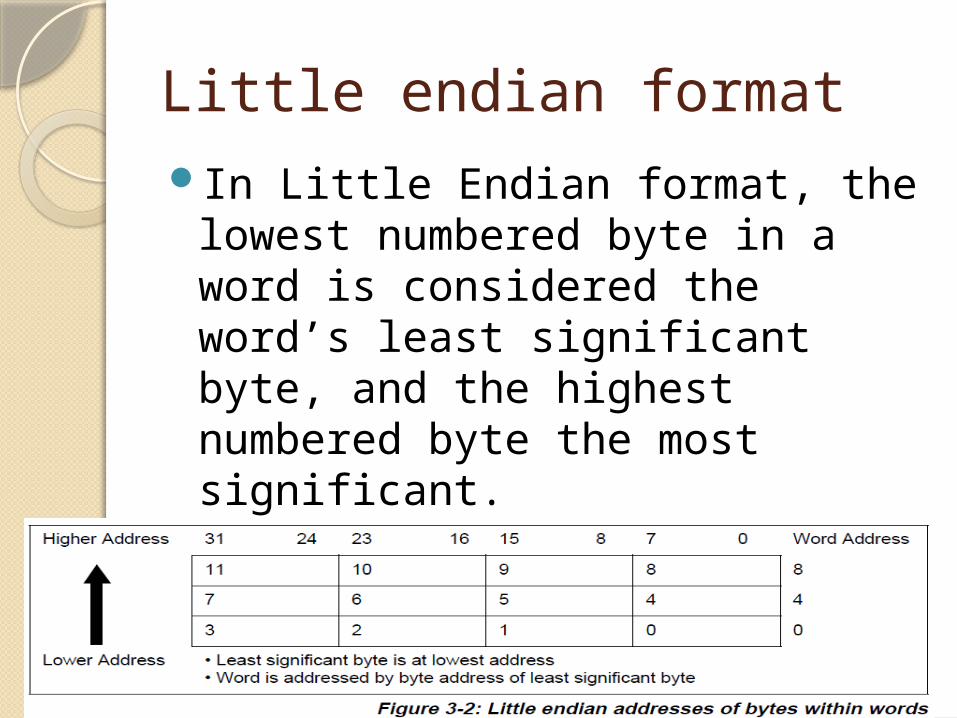
Little endian formatIn Little Endian format, the
lowest numbered byte in a word is considered the word’s least significant byte, and the highest numbered byte the most significant.
Byte 0 of the memory system is therefore connected to data lines 7 through 0.
R.K.Tiwari([email protected])
Instruction LengthInstructions are either 32 bits long
(in ARM state) or 16 bits long (in THUMB state)
Data Types ARM7TDMI supports byte (8-bit),
halfword (16-bit) and word (32-bit) data types.
Words must be aligned to four-byte boundaries and half words to two-byte boundaries.
R.K.Tiwari([email protected])
Operating ModesARM7TDMI supports seven modes of
operation:User (usr): The normal ARM program
execution stateFIQ (fiq): Designed to support a data transfer
or channel process IRQ (irq): Used for general-purpose interrupt
handlingSupervisor (svc): Protected mode for the
operating systemAbort mode (abt): Entered after a data or
instruction prefetch abortSystem (sys): A privileged user mode for the
operating systemUndefined (und): Entered when an undefined
instruction is executed
R.K.Tiwari([email protected])
RegistersARM7TDMI has a total of 37
registers - 31 general-purpose 32-bit registers and six status registers - but these cannot all be seen at once.
The processor state and operating mode dictate which registers are available to the programmer.
R.K.Tiwari([email protected])
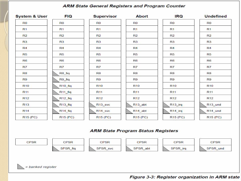
The ARM state register setIn ARM state, 16 general registers
and one or two status registers are visible at any one time. In privileged (non-User) modes, mode-specific banked registers are switched in.
Figure 3-3: Register organization in ARM state shows which registers are available in each mode: the banked registers are marked with a shaded triangle.
R.K.Tiwari([email protected])
The ARM state register setThe ARM state register set
contains 16 directly accessible registers:
R0 to R15. All of these except R15 are general-purpose, and may be used to hold either data or address values.
In addition to these, there is a seventeenth register used to store status information
R.K.Tiwari([email protected])
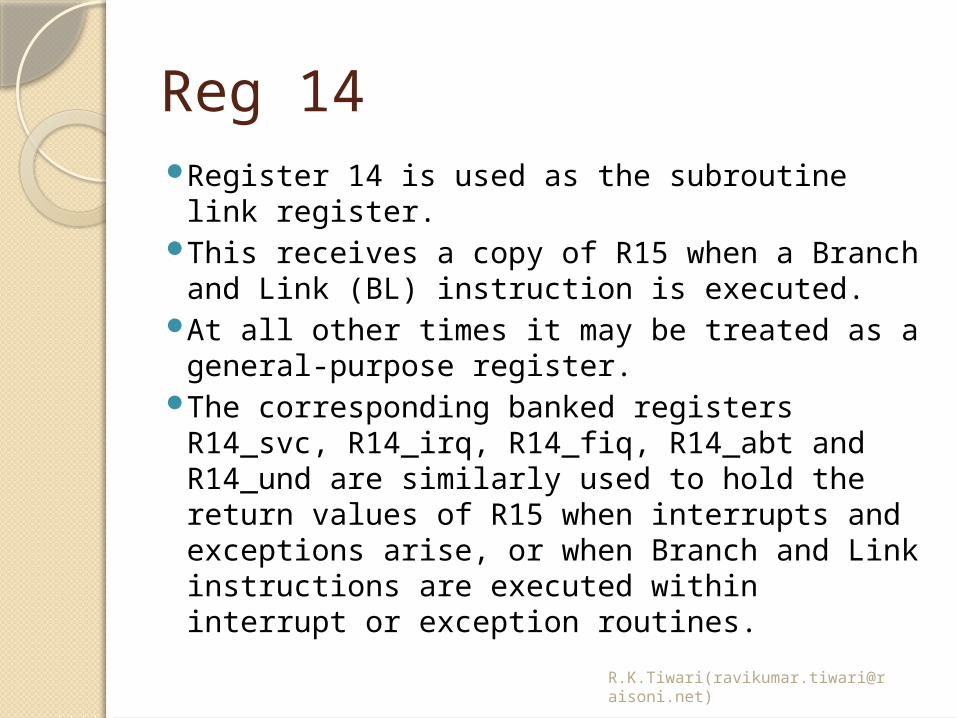
Reg 14Register 14 is used as the subroutine link
register.This receives a copy of R15 when a Branch
and Link (BL) instruction is executed. At all other times it may be treated as a
general-purpose register. The corresponding banked registers R14_svc,
R14_irq, R14_fiq, R14_abt and R14_und are similarly used to hold the return values of R15 when interrupts and exceptions arise, or when Branch and Link instructions are executed within interrupt or exception routines.
R.K.Tiwari([email protected])
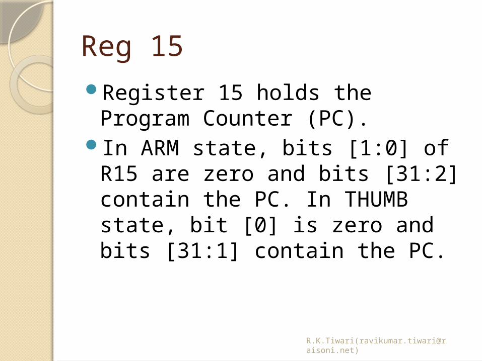
Reg 15Register 15 holds the Program
Counter (PC). In ARM state, bits [1:0] of R15
are zero and bits [31:2] contain the PC. In THUMB state, bit [0] is zero and bits [31:1] contain the PC.
R.K.Tiwari([email protected])
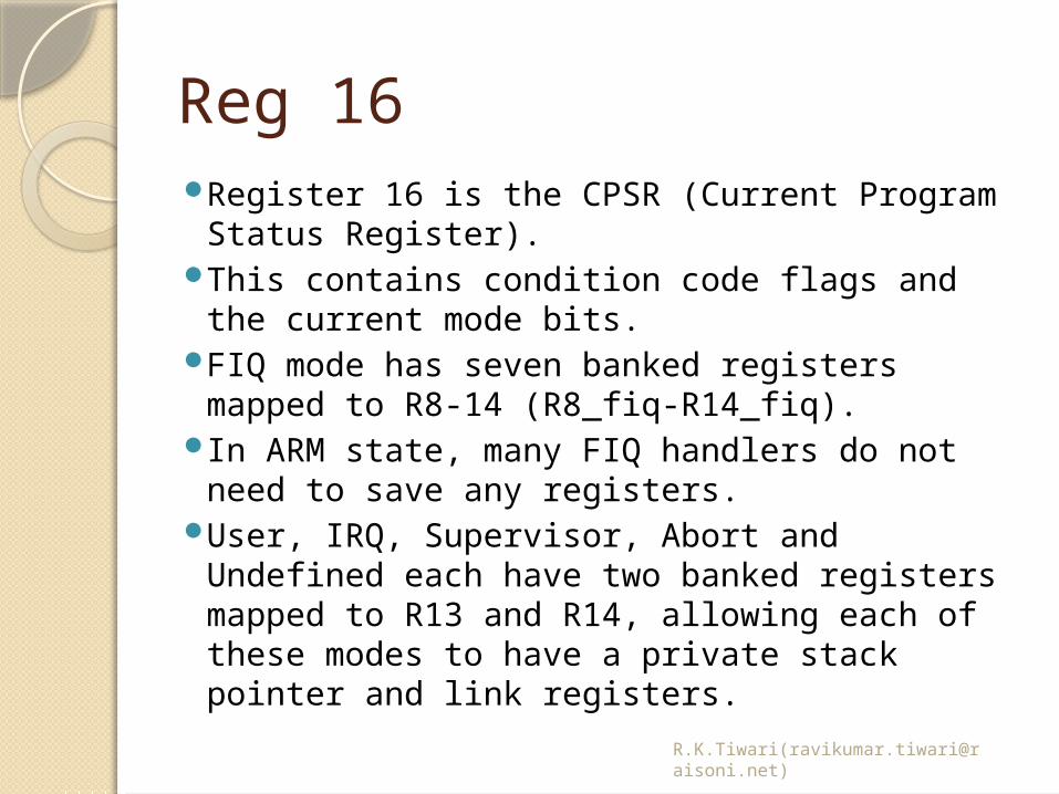
Reg 16Register 16 is the CPSR (Current Program
Status Register). This contains condition code flags and the
current mode bits.FIQ mode has seven banked registers mapped
to R8-14 (R8_fiq-R14_fiq). In ARM state, many FIQ handlers do not need
to save any registers. User, IRQ, Supervisor, Abort and Undefined
each have two banked registers mapped to R13 and R14, allowing each of these modes to have a private stack pointer and link registers.
R.K.Tiwari([email protected])
R.K.Tiwari([email protected])
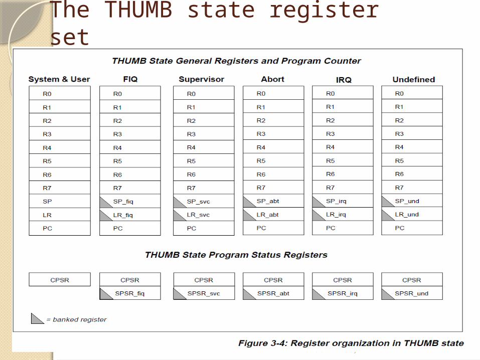
The relationship between ARM and THUMB state registersThe THUMB state registers relate to the
ARM state registers in the following way:•THUMB state R0-R7 and ARM state R0-R7
are identical• THUMB state CPSR and SPSRs and ARM
state CPSR and SPSRs are identical• THUMB state SP maps onto ARM state
R13THUMB state LR maps onto ARM state R14• The THUMB state Program Counter maps
onto the ARM state Program Counter (R15)
R.K.Tiwari([email protected])
The Program Status Registers
The ARM7TDMI contains a Current Program Status Register (CPSR), plus five Saved Program Status Registers (SPSRs) for use by exception handlers.
These registers• hold information about the most
recently performed ALU operation• control the enabling and disabling of
interrupts• set the processor operating mode
R.K.Tiwari([email protected])
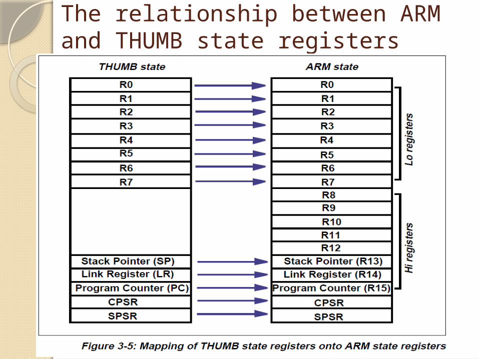
Program Status RegistersThe condition code flagsThe N, Z, C and V bits are the
condition code flags. These may be changed as a result
of arithmetic and logical operations, and may be tested to determine whether an
instruction should be executed.
R.K.Tiwari([email protected])
Program Status RegistersThe control bitsThe bottom 8 bits of a PSR
(incorporating I, F, T and M[4:0]) are known collectively as the control bits.
These will change when an exception arises.
If the processor is operating in a privileged mode, they can also be manipulated by software.
R.K.Tiwari([email protected])
Program Status RegistersThe T bit This reflects the operating state. When
this bit is set, the processor is executing in THUMB state, otherwise it is executing in ARM state.
This is reflected on the TBIT external signal.
**Note that the software must never change the state of the TBIT in the CPSR. If this happens, the processor will enter an unpredictable state.
R.K.Tiwari([email protected])
Program Status RegistersInterrupt disable bits The I and F bits are the interrupt
disable bits. When set,these disable the IRQ
and FIQ interrupts respectively.
R.K.Tiwari([email protected])
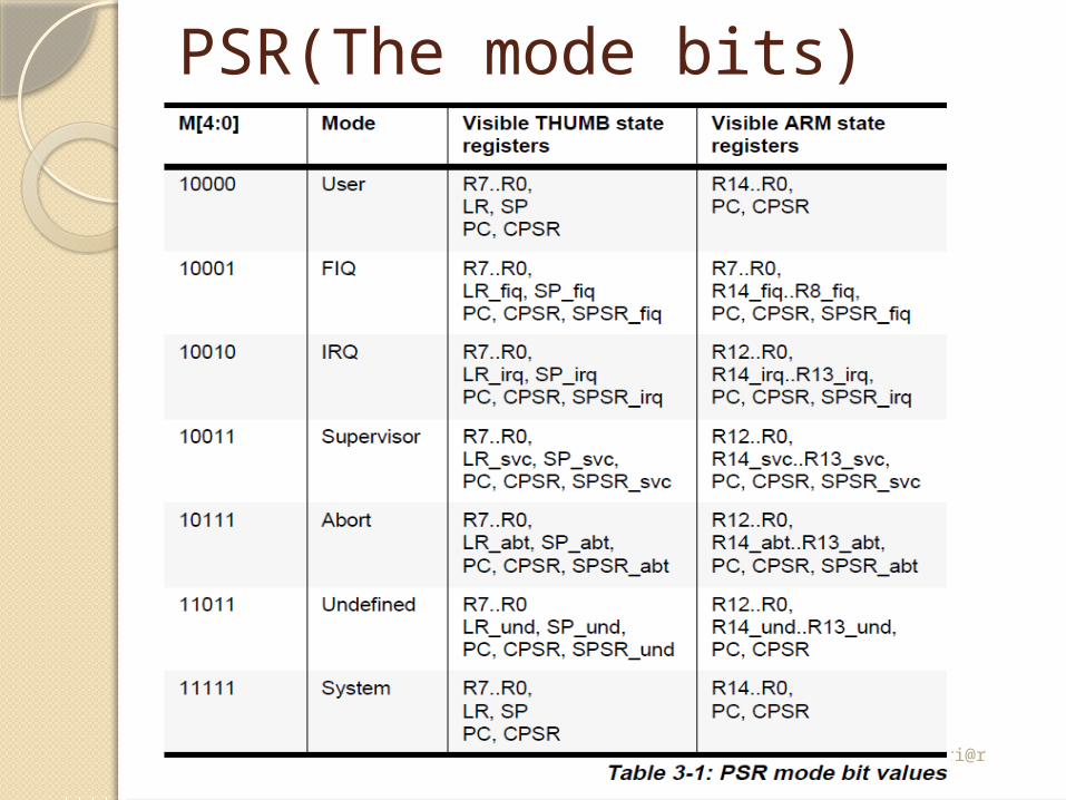
PSR(The mode bits)The M4, M3, M2, M1 and M0 bits (M[4:0]) are
the mode bits. These determine the processor’s operating
mode, as shown in òTable 3-1: PSR mode bit values on page 3-9.
Not all combinations of the mode bits define a valid processor mode. Only those explicitly described shall be used.
The user should be aware that if any illegal value is programmed into the mode bits, M[4:0], then the processor will enter an unrecoverable state.
If this occurs, reset should be applied.
R.K.Tiwari([email protected])
PSR(Reserve bits)The remaining bits in the PSRs
are reserved. When changing a PSR’s flag or
control bits, you must ensure that these unused bits are not altered.
Also, your program should not rely on them containing specific values, since in future processors they may read as one or zero.
R.K.Tiwari([email protected])
ExceptionExceptions arise whenever the
normal flow of a program has to be halted temporarily, for example to service an interrupt from a peripheral.
Before an exception can be handled, the current processor state must be preserved so that the original program can resume when the handler routine has finished.

R.K.Tiwari([email protected])
ExceptionIt is possible for several
exceptions to arise at the same time.
If this happens, they are dealt with in a fixed order

R.K.Tiwari([email protected])
Action on entering an exception
When handling an exception, the ARM7TDMI..
Preserves the address of the next instruction in the appropriate Link Register. If the exception has been entered from ARM state, then the address of the next instruction is copied into the Link Register
Copies the CPSR into the appropriate SPSR

R.K.Tiwari([email protected])
Action on entering an exceptionForces the CPSR mode bits to a
value which depends on the exception
Forces the PC to fetch the next instruction from the relevant exception vector

R.K.Tiwari([email protected])
Action on leaving an exception
On completion, the exception handler:
1 Moves the Link Register, minus an offset where appropriate, to the PC. (The
offset will vary depending on the type of exception.)
2 Copies the SPSR back to the CPSR
3 Clears the interrupt disable flags, if they were set on entry

R.K.Tiwari([email protected])
Exception priorities
When multiple exceptions arise at the same time, a fixed priority system determines the order in which they are handled

R.K.Tiwari([email protected])
Exception prioritiesHighest priority:1 Reset2 Data abort3 FIQ4 IRQ5 Prefetch abortLowest priority:6 Undefined Instruction, Software interrupt.*Not all exceptions can occur at once:
Undefined Instruction and Software Interrupt are mutually exclusive, since they each correspond to particular (non-overlapping) decodings of the current instruction.

R.K.Tiwari([email protected])
ResetWhen the nRESET signal goes
LOW, ARM7TDMI abandons the executing instruction and then continues to fetch instructions from incrementing word addresses.

R.K.Tiwari([email protected])
ResetWhen nRESET goes HIGH again, ARM7TDMI:1 Overwrites R14_svc and SPSR_svc by
copying the current values of the PCand CPSR into them. The value of the
saved PC and SPSR is not defined.2 Forces M[4:0] to 10011 (Supervisor
mode), sets the I and F bits in the CPSR,and clears the CPSR’s T bit.3 Forces the PC to fetch the next
instruction from address 0x00.4 Execution resumes in ARM state.