Embed Size (px)
Citation preview
VETENSKAPt» OCH
KONST
KUNGLTEKNISKAHÖGSKOLAN
TRITA-EEA-9302ISSN 1100-1593
ANALYTICAL METHODS FORSTUDY OF TRANSMISSION LINE
LIGHTNING PROTECTION
Per Pettersson
Royal Institute of TechnologyDept. of Electric Plant Engineering
Stockholm, Sweden mum * us mum ttmm SAW mma
ANALYTICAL METHODS FOR STUDY OF TRANSMISSION LINELIGHTNING PROTECTIONby Per PetterssonRoyal Institute of TechnologyDepartment of Electric Plant EngineeringS-100 44 Stockholm, SwedenTRTTA-EEA-9302, ISSN 1100-1593, ISBN 91-7170-124-9
Abstract
Transmission line lightning performance is studied by analytical methods. Theelements of shielding failure flashovers and back-flashovers are analysed asfunctions of incidence, response and insulation. Closed-form approximateexpressions are sought to enhance understanding of the phenomena. Probabilisticand wave propagation aspects are particularly studied.
The electrogeometric model of lightning attraction to structures is used incombination with the log-normal probability distribution of lightning to groundcurrents. The log-normality is found to be retained for the currents collected bymast-type as well as line-type structures, but with a change of scale. For bothtypes, exceedingly simple formulas for the number of hits are derived.
Simple closed-form expressions for the line outage rates from back-flashovers andshielding failure flashovers are derived in a uniform way as functions of the criticalcurrents. The expressions involve the standardized normal distribution function.
System response is analysed by use of Laplace transforms in combination with text-book transmission-line theory. Inversion into time domain is accomplished by anapproximate asymptotic method producing closed-form results. The back-flashoverproblem is analysed in particular.
Approximate, image-type expressions are derived for shunt admittance of wiresabove, on and under ground for analyses of fast transients. The derivation parallelsthat for series impedance, now well-known.
Key-words: Transmission line, lightning, incidence, failure rate, back-flashover,shielding failure, probabilistic, electrogeometric, travelling wave, frequencydependence, shield wire, continuous counterpoise, grounding.
ANALYTICAL METHODS FORSTUDY OF TRANSMISSION LINE
LIGHTNING PROTECTION
Per Pettersson
Akademisk avhandling
som med tillstånd • Kungliga Tekniska Högskolan framlägges till offentliggranskning för avlägg .nde av teknisk doktorsexamen onsdagen den 2 juni 1993kl. 14.00 i Kollegk ilen, Administrationsbyggnaden, KTH, Valhallavägen 79,Stockholm. AvhandlL ;en försvaras på svenska.
TRITA-EEA-93D2ISSN 1100-1597
ANALYTICAL METHODS FORSTUDY OF TRANSMISSION LINE
LIGHTNING PROTECTION
Per Pettersson
VETENSKAPOCH
KONST
Royal Institute of TechnologyDept. of Electric Plant Engineering
Stockholm, Sweden
MASTERtf US OOCta B ULffltt)
mum-mo ?
Abstract
Transmission line lightning performance is studied by analytical methods. Theelements of shielding failure flashovers and back-flashovers are analysed asfunctions of incidence, response and insulation. Closed-form approximateexpressions are sought to enhance understanding of the phenomena. Probabilisticand wave propagation aspects are particularly studied.
The electrogeometric model of lightning attraction to structures is used incombination with the log-normal probability distribution of lightning to groundcurrents. The log-normality is found to be retained for the currents collected bymast-type as well as line-type structures, but with a change of scale. For bothtypes, exceedingly simple formulas for the number of hits are derived.
Simple closed-form expressions for the line outage rates from back-flashover andshielding failure flashovers are derived in a uniform way as functions of thecritical currents. The expressions involve the standardized normal distributionfunction.
System response is analysed by use of Laplace transforms in combination withtext-book transmission-line theory. Inversion into time domain is accomplishedby an approximate asymptotic method producing closed-form results. The back-flashover problem is analysed in particular.
Approximate, image-type expressions are derived for shunt admittance of wiresabove, on and under ground for analyses of fast transients. The derivationparallels that for series impedance, now well-known.
Kev-words: Transmission line, lightning, incidence, failure rate, back-flashover,shielding failure, probabilistic, electrogeometric, travelling wave, frequencydependence, shield wire, continuous counterpoise, grounding.
Preface
The epithet "analytical" used in the title of the thesis is not well-defined and allmethods for acquiring understanding of physical processes may be calledanalytical. Here the word analytical is used in a more strict sense as synonymouswith expressing the relations between the quantities involved in closed-formfunctional relationships.
The body of the thesis is seven papers, some published and some in process. Theirmain results have been extracted to form an introductory text. The reader of this issupposed to be reasonably familiar with the subject, and standard text-bookmaterial is excluded in order to highlight my own work. Also for concision, paperreferences have been left out, but the reader will have no trouble in finding themin the papers. This goes also for the exact definition of some quantities appearing.
I am grateful to my company Vattenfall AB for giving me the opportunity to dothis research, which may have gone beyond the most urgent needs.
To Prof. Roland Eriksson, who has been my supervisor at the Royal Institute ofTechnology, and who gave the impetus to my dissertation, I want to express mydeep-felt gratitude. He has shared with me his expert knowledge and has alwayshad a faith in me. Much work has been relieved from me by my secretary MonicaNilsson, who did the word-processing, and by Carl Johan Dahlberg, who did thevalidating computer programming. To both of them, I owe my sincere gratitudefor their unfailing patience. Thanks are also due to my other colleagues atVattenfall Utveckling AB, Power Technology, and Electric Power ResearchCentre at the Royal Institute of Technology for constituting the necessary creativeenvironment.
My love goes unshared to my wife Lillian, who has long been standing a husbandwith his head stuck up into a thunder-cloud.
Stockholm Per PetterssonApril 1993

CONTENTS
1. INTRODUCTION 1
2. INCIDENCE 3
3. FAILURE RATE 5
4. RESPONSE 9
5. WAVE PROPAGATION 12
6. SUMMARY IS
REFERENCES
PAPERS
List of papers
Paper 1
Paper 2
Paper 3
Paper 4
Paper 5
Paper 6
Paper 7
Errata to the papers
I. INTRODUCTION
Besides to providing a long-term continuous insulation for operational voltage,the design of electric power systems insulation has to consider also short-durationmore or less frequent overvoltages of various origins and amplitudes. Insulationfailure may damage the utility's own equipment by the thermal and mechanicalpower released, but more important are the consequences for society which hasbecome relying on a high-quality power supply. For bulk power overhead linetransmission over long distances, due to a great exposure, the most frequent causeof interruptions is usually lightning.
Lightning faults on a line can mostly be cleared by fast opening and reclosure ofthe terminal circuit breakers so that the interruption of power flow will be justmomentary. In well-meshed transmission networks, power will instantly beredistributed amongst the other lines. The faults are nevertheless unwanted as theprotective operations may go wrong, and as the customer may not tolerate even amomentary loss or degradation of supply. Arresters, in absorbing the lightningenergy and leaving the power supply intact, do not have these drawbacks and areincreasingly used, especially in heavily exposed conditions. Cost aspects are,however, a limiting factor for a wider application.
Taking its idea from protection of buildings, installation of shield wires above thephase conductors was early found to be an effective and cheap counter-measureagainst lightning strokes. A direct hit on a phase conductor is likely to cause aflashover, almost no matter how high the insulation level may be. The voltagestress is calculated as half the peak lightning current, which is typically some tenkA, multiplied by the surge impedance of the phase conductor, 300 to 400 ft say,meaning several MV of applied voltage. Swedish 400 kV-lines, for example, areprovided with less than l.S MV insulation to ground. The effectiveness of theshield wire is mainly depending on two factors: actually catching the stroke, anddiverting its current to electric ground with low voltage build-up in down-leadsand earthing electrodes. From Swedish outage statistics it is concluded that use ofshield wire may bring down the lightning failure rate to about one tenth.
Lightning performance targeted design, for new lines and for improvements onexisting ones, requires analytical tools to strike an economic balance ofconstruction and equipment costs versus reliability-related costs. Despite of a vastamount of experience and research, regarding lightning as a natural phenomenonand its impact on overhead lines, we have to face the fact that understanding isincomplete. This is evidenced by the rather poor precision showu in the lightning
outage-rates predicted for the new lines erected following the increase in voltagelevel through the years. Generally, the increased insulation, dimensioned mainlyfor internal overvoltages, did not act as beneficial as was expected. There are alsoexamples where line designs working well in favourable lightning climatic andorographic conditions have been directly applied in more hostile environmentswith frustrating results.
The philosophy of this thesis is that there is little point in using analyticalmethods of complexity exceeding input data accuracy. Use of modem computersmay make it tempting to introduce more sophisticated models than is warrantedby actual knowledge of the physical process. One danger is that simple basicrelations, which are necessary for the engineers comprehension of the problem,may get lost. The object of this thesis therefore, is to present closed-formsolutions to some basic problems in transmission line lightning studies.
The thesis is based on seven papers which have been classified to fall into fourcategories. Paper 1 deals with the incidence of lightning, which is the topic ofSection 2. The theory of the paper is quite general and the brief presentation herehas been confined to cover aspects of direct strikes to transmission lines only. Thesecond category, dealt with in Section 3, is about estimation of lightning failurerate, and Papers 2 and 3 belong here. Shielding failure flashovers and back-flashovers are treated in a unified setting departing from the concept of attractivezone of the so called electrogeometric model of lightning attraction to objects. Forthe back-flashover case, assumed given is the critical current, which if injectedinto the line by the flash would be just high enough to cause a flashover. Thedetermination of this critical current belongs to Section 4 about lightningresponse. Taking a cue from Paper 4, where die potential on the shield wire isstudied, Paper S addresses the more general lightning system response problem.The studies make extensive use of elementary transmission-line theory. Thistheory is approximate and is sometimes not applicable. Papers 6 and 7 of SectionS stan out from more basic wave-propagation principles in an attempt to findapproximate closed-form expressions for the transmission line parameters foraccurate lightning surge propagation modelling, taking the finite conductivity ofthe ground into consideration. Only overhead wires is the subject of Paper 6. InPaper 7, the theory is generalized to apply to wires on and below the surface ofground as well.
The summary-like presentation to follow is for brevity almost devoid ofreferences, since the reader will have no trouble in finding them in the paperaddressed. After the bulk of the papers was written, two publications have been

released which can be said to be defining the state-of-the-art. They are entries [1]and [2] of the shon list of references. Reference [3] is added since it contains acase study of insulation dimensioning using some of the results of the thesis.
2. INCIDENCE
This relates to the frequency of hits on the component parts of a line (tower, span,phase-conductor, shield wire etc), and the characteristics of the injected return-stroke currents, particularly their amplitudes. These amplitudes show a greatvariation between flashes and the concept of random variable serves tocharacterize their unpredictable nature. A random variable is characterized by itsprobability distribution. It is then assumed that the current is intrinsic to the flashand is not depending of the object struck. Since the harmful voltages occurring inthe system depend on the current amplitude, one question arising is if the currentdistribution of those flashes which are hitting the system of study is different fromthe distribution of all currents of lightning to ground. Another problem regards thefrequency of hits on the system. Both these problems, and some related ones areaddressed in Paper 1. which contains a unified comprehensive theory for directand indirect lightning strikes. Attention is directed to the direct hits in the thesis.
In the paper, a general concept of "perception" is defined so as to cover theessential aspects of direct and indirect lightning incidence to systems. For directlightning strikes to a structure, perception means just that it is struck. Figure 1illustrates a mast or tower of some kind being struck. The lightning leader tip issupposed to be approaching ground at some angle Y, a random variable, andproceed unaffected by the mast towards a projected terminal point on the ground.
Figure 1 The electrogeometric model
S= Striking distance
¥= Leader approachangle to ground
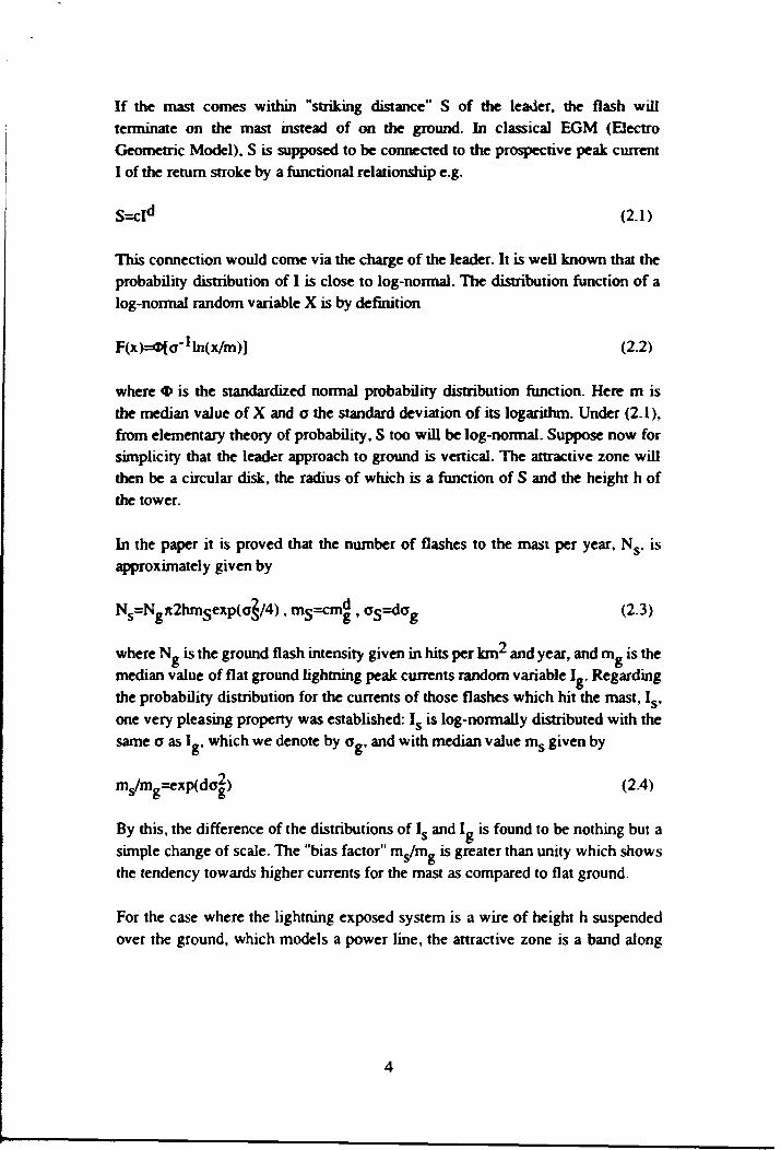
If the mast comes within "striking distance" S of the leader, the flash willterminate on the mast instead of on the ground. In classical EGM (ElectroGeometric Model), S is supposed to be connected to the prospective peak currentI of the return stroke by a functional relationship e.g.
S=cld (2.1)
This connection would come via the charge of the leader. It is well known that theprobability distribution of I is close to log-normal. The distribution function of alog-normal random variable X is by definition
F(x)=«I>la-1ln(x/m)] (2.2)
where <D is the standardized normal probability distribution function. Here m isthe median value of X and a the standard deviation of its logarithm. Under (2.1),from elementary theory of probability, S too will be log-normal. Suppose now forsimplicity that the leader approach to ground is vertical. The attractive zone willthen be a circular disk, the radius of which is a funaion of S and the height h ofthe tower.
In the paper it is proved that the number of flashes to the mast per year, N s , isapproximately given by
Ns=Ngn2hmsexp(o§/4), ms=cm^ , o s =do g (2.3)gn2hmsexp(o§/4), ms=cm^ , o s=dog
where NR is the ground flash intensity given in hits per \anr and year, and m_ is themedian value of flat ground lightning peak currents random variable I». Regardingthe probability distribution for the currents of those flashes which hit the mast, Is,one very pleasing property was established: I s is log-normally distributed with thesame o as I™, which we denote by o g . and with median value ms given by
ms/mg=exp(da|) (2.4)
By this, the difference of the distributions of Is and Ig is found to be nothing but asimple change of scale. The "bias factor" ms/mK is greater than unity which showsthe tendency towards higher currents for the mast as compared to flat ground.
For the case where the lightning exposed system is a wire of height h suspendedover the ground, which models a power line, the attractive zone is a band along
the wire. The width of the band is twice the radius of the disk in the mast case, forequal S and h. The relations corresponding to (2.3) and (2.4) are
Ns=Ng2(2hms)I'-exp(oJ/8) (2.5)
(2.6)
where N s is now given in per m of wire length. It is noted that the bias factor issmaller than that of the mast case, viz. the square-root.
For illustration of the practical implications of the above results, we will use c=8and d=0.6S from [1], and a»=0.60 from [2], while the value to put on mR will beleft open for a moment. This gives a bias factor of 1.26 for mast and 1.12 for wire.According to measurements on towers ms=33 kA, [2], giving mg=2b kA andconsequently ms=29 kA for wires. Regarding N s , it is first noted that theexponents of the exponential factors in (2.3) and (2.5) will be very small wherebythe factors may be set equal to unity, which means some simplification to theexpressions. An idea of the physical dimensions is given by the median value ofS, mg, which is 67 m.
Inserting N g=l , h=20 m, and mg, as calculated above, into (2.5) would give atypical transmission line in Swedish lightning conditions a hit rate about 10 per100 km and year, and 7 for h=10 m. For the unshielded 220 kV lines in northernSweden where the lightning activity is less, say N~=0.5, the actual failure rate is 3-4 from failure statistics. Unshielded 130 kV lines in Sweden, predominantlysituated in the southern part, have about the same failure rate as the unshielded220 kV lines. Taking in account some uncertainty about N_, which may be lower,the model still seems to overestimate the rate. This discrepancy can however bewell explained by the shielding effect of the forestation, which effectivelydecreases h for long line sections.
3. FAILURE RATE
There are two basic ways in which a transmission line can flashover: inducedovervoltage flashover where lightning hits the ground or an object near by theline, so that the induced effects cause the flashover, and flashover at a direct hit.Induced flashovers are of importance only for distribution lines of low insulationand will not be treated here. For direct strikes two modes of flashover areidentified
* Back-flashover(BF). The leader is intercepted by the shield wires asintended, but the line insulation cannot still withstand the voltagescreated.
* Shielding failure flashover (SFF). The shield wire fails to intercept theleader which hits on a phase conductor.
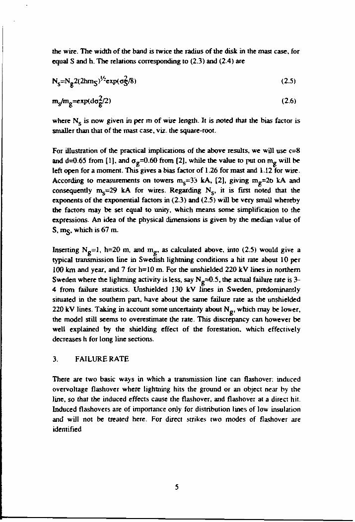
From a probabilistic point of view, the two modes have a certain structure incommon. This comes from the concept of attractive zone which was introduced inthe preceding section. The one-sided attractive zone is for each of the flashovermodes an imagined strip on the ground on one side of the line so that flashesaiming into the strip will be intercepted by the line, hitting the shield wire in theBF case and a phase-conductor in the SFF case. In the general case, the zones willdiffer for the two sides. Figure 2 illustrates the exposure of a line using EGM.Strikes to the imagined circular arcs of radius S centered at shield wire andconductor will hit these respectively. Strikes to the right of these arcs will hitground. Here w denotes the width of the one-sided attractive zone.
For flashover to occur, not only must the line be hit, but the current injected mustalso be of amplitude high enough to cause insulation failure. This is the case forboth failure modes, though the critical currents ic are different. For SFF, ic is givenas indicated in Section 1, i.e. twice the insulator string voltage withstand leveldivided by phase-conductor surge impedance. For BF, the determination of ic istreated in Section 4.
Figure 2 Definition of attractivezone width
= back-flashovers
shielding failureflashovers
- shielding angle
= average height ofshield-wire andphase-conductor
8
h
I- WSFF =
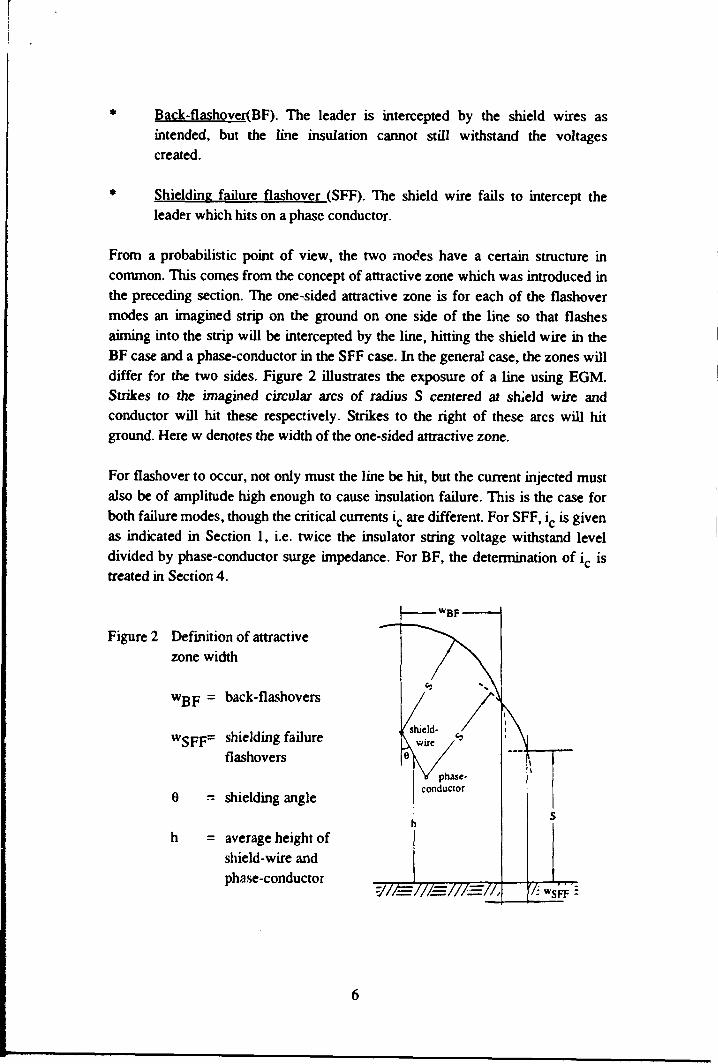
Assuming symmetry of the line for simplicity, the flashover rate per 100 km ofline and year is seen to be given by
soA.=0.2NgJ w(s)fs(s)ds (3.1)
s l
with w given in m. Here fg is the probability density function of S. The quantity s jis the striking distance corresponding to critical current ic through the relationship(2.1), i.e. spcij?, and S2 is the maximum striking distance. For BF S2 is infinity. ForSFF, it is seen from Figure 2 that for increasing s there will be a finite value S2 forwhich the arc vanishes. If si ^ the line will be perfectly shielded.
Because of the power law relationship in (2.1), as was noted in Section 2, S willbe log-normally distributed if Ig is. Moreover, if w is of power type as a functionof s, or a sum of such, then the integral in (3.1) can be evaluated analytically. InPaper 2 it is shown that, for each of the flashover modes, w is at leastapproximately of power type, namely
(3.2)
for backflashes and
wSFF*htge(l-s/s2), s2*h/(l-sin0) (3.3)
for shielding failure flashovers. Eq. (3.3) contains the first two terms in the seriesexpansion of the exact wgpp into powers of s at S2- It is proved in the paper that theflashover rates are approximately given by
XBF=0.2Ng(2hms)'^exp(o§/8)[l-<I>(z1-os/2)] (3.4)
XSFF=0.2Nghtge{[aKz2)-<I>(z1)] (3.5)
-(ms/s2)exp(o§/2)[«I»(z2-os)-<I»(z1-os)]}
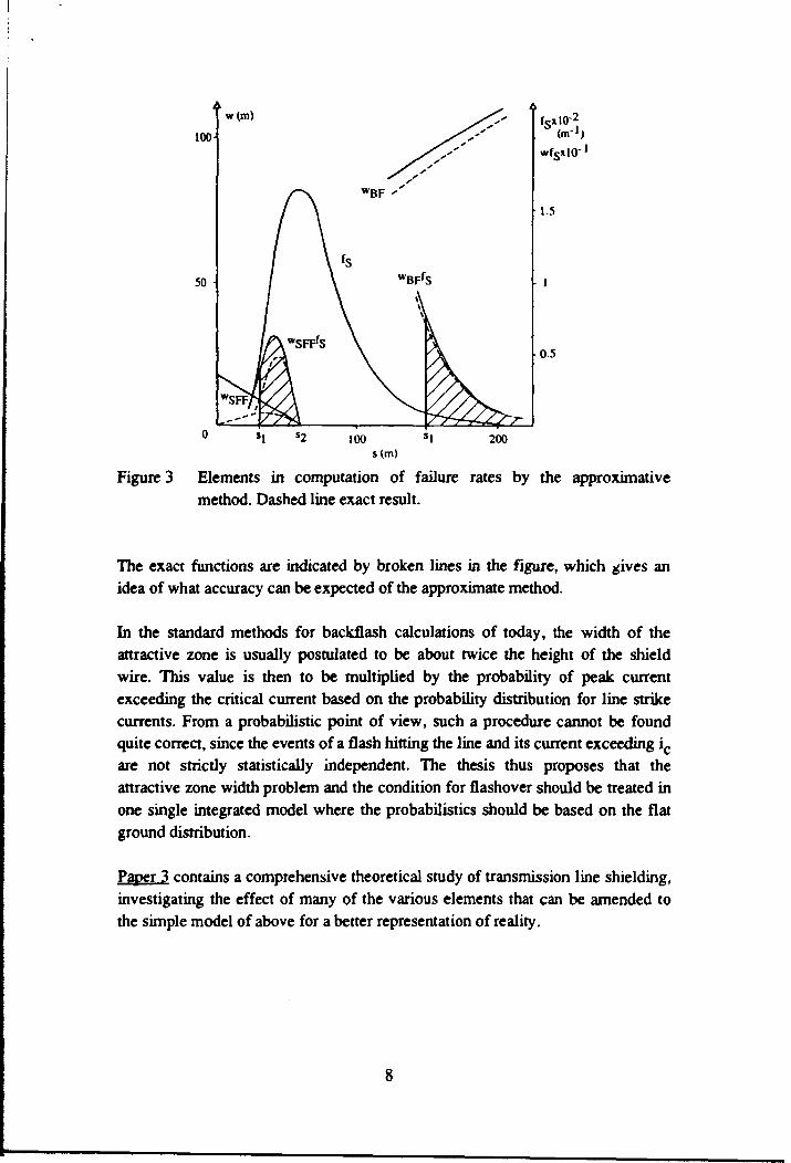
Figure 3 illustrates the computations for a particular numerical case with 9=30°,h=30 m, ic=90 kA for BF and 8 kA for SFF (about 2.2 m sparking distance). Theformulas above predict X,gp=0.40 and kgpp=0.26.
(nr1)
1.5
05
200
Figure 3 Elements in computation of failure rates by the approximativemethod. Dashed line exact result.
The exact functions are indicated by broken lines in the figure, which gives anidea of what accuracy can be expected of the approximate method.
In the standard methods for backflash calculations of today, the width of theattractive zone is usually postulated to be about twice the height of the shieldwire. This value is then to be multiplied by the probability of peak currentexceeding the critical current based on the probability distribution for line strikecurrents. From a probabilistic point of view, such a procedure cannot be foundquite correct, since the events of a flash hitting the line and its current exceeding ic
are not strictly statistically independent. The thesis thus proposes that theattractive zone width problem and the condition for flashover should be treated inone single integrated model where the probabilistics should be based on the flatground distribution.
Paper 3 contains a comprehensive theoretical study of transmission line shielding,investigating the effect of many of the various elements that can be amended tothe simple model of above for a better representation of reality.
The study departs from an idealistic basic case and investigates the effect ofalternative modelling of lightning itself, of incorporating orographic parameters,and of a more precise modelling of the tower top geometry. Regarding the lastpoint, Eq. (3.5) does not contain the separation between shield wire and phase-conductor as a parameter. In fact the separation was neglected, and the studyshows that this can be justified. The effect of representing the leader approachangle as a random variable with a rather adverse distribution was found to bemoderate. The effect of unequal striking distances to ground and to conductor wasfound to be equivalent to a change of the effective line height, which is a firstorder parameter. Lateral slope in landscape was seen to effectively change theshielding angle, and must also be considered to be of primary importance.
The effect of all the above mentioned factors were found to be possible to analyseby closed-form methods.
4. RESPONSE
The problem of assessing the voltages stressing the insulation of an electricinstallation at a lightning strike is in general very complex due to the wavepropagation phenomena occurring in the system of conductors diverting thelightning current to electric ground. Given the point where lightning strikes, andgiven the voltage withstand capability of an insulating element, the task is todetermine the maximum current ic that can be injected without insulation break-through. Concern of wave propagation becomes especially important when thestrike point and the point of study are distant from each other, and when theearthing electrodes are spatially extended.
Papers 4 and 5, classified for this section, rely both on the applicability of thetransmission-line modelling of wave propagation, as is current engineering praxis.The next section will deal with the feasibility of a more accurate modellingdeparting from electromagnetic theory first-hand principles.
Paper 4 studies the potentials occurring on the shield wire of a transmission line ata lightning stroke. These potentials are determining for the voltage stress of theinsulator chains. The situation is shown in Figure 4. Lightning strikes the shieldwire somewhere in the span or possibly at the tower top. The current splits in halfand electromagnetic waves are travelling away in both directions, the relationbetween voltage and current being given by the surge impedance of the shieldwire.
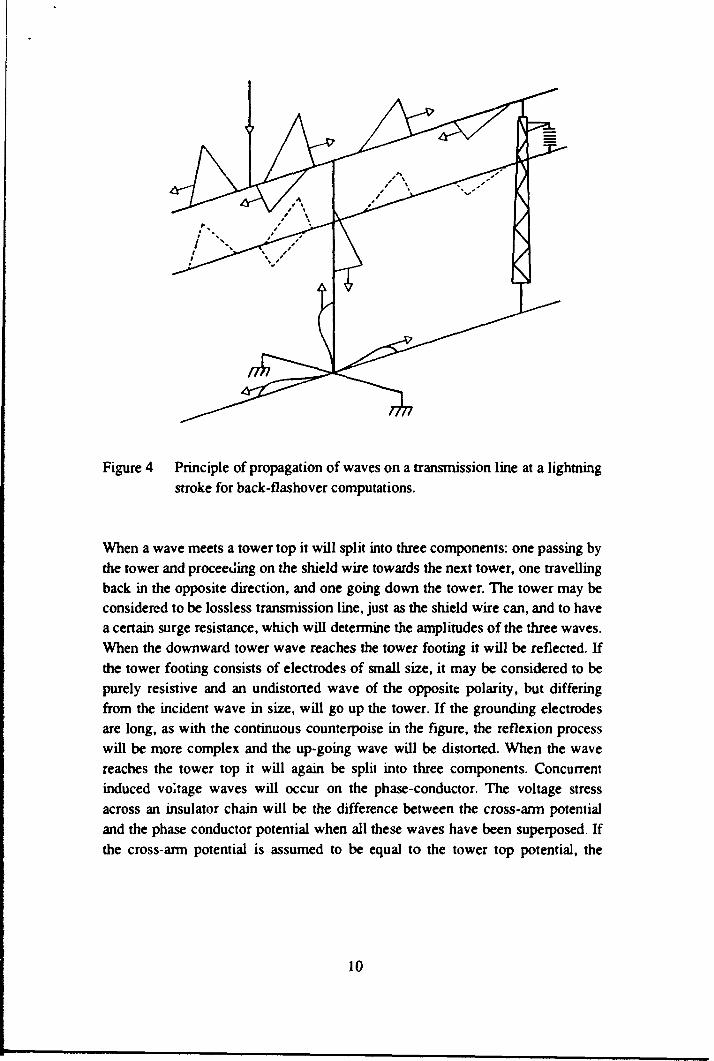
Figure 4 Principle of propagation of waves on a transmission line at a lightningstroke for back-flashover computations.
When a wave meets a tower top it will split into three components: one passing bythe tower and proceeding on the shield wire towards the next tower, one travellingback in the opposite direction, and one going down the tower. The tower may beconsidered to be lossless transmission line, just as the shield wire can, and to havea certain surge resistance, which will determine the amplitudes of the three waves.When the downward tower wave reaches the tower footing it will be reflected. Ifthe tower footing consists of electrodes of small size, it may be considered to bepurely resistive and an undistorted wave of the opposite polarity, but differingfrom the incident wave in size, will go up the tower. If the grounding electrodesare long, as with the continuous counterpoise in the figure, the reflexion processwill be more complex and the up-going wave will be distorted. When the wavereaches the tower top it will again be split into three components. Concurrentinduced voltage waves will occur on the phase-conductor. The voltage stressacross an insulator chain will be the difference between the cross-arm potentialand the phase conductor potential when all these waves have been superposed Ifthe cross-arm potential is assumed to be equal to the tower top potential, the
10
voltage stress will be this potential multiplied by 1-k, where k is the couplingfactor between shield wire and phase conductor.
The customary way of study is by the "lattice" method, meaning book-keepingand summing of all the reflected and transmitted waves created. No method toaccount for a continuous counterpoise has been found in the literature.
The proposed alternative method, using Laplace transforms, takes a more overallview on the problem and results in closed-form analytical expressions. The mainresult is that, as a sound approximation, the relation between shield-wire potentialv(t) and lightning current i(t) as functions of time t can be written as
v(t)= &* [^ Rzp(t)]^rH(I) (4.1)
r=r(i+p)r^(i-a)/r[P+u-a)/2]
where i and R are the one-way span travel time and surge impedance,respectively, and zp(t) is the voltage response function to unit step currentexcitation of a tower grounding. The constants a and P are defined by the basicassumptions that, up to constants, zp(t)~t"a and i(t)~tP resp., for large t. Forconcentrated groundings a=0 and for extended ones a=l/2. H, close to unity forlarge t, is a correction term reflecting the transient wave propagation in towersand spans, and the location of the strike point in the span. H has as parameters Tand R as defined above, and the travel time and surge impedance of the tower. Forcomputing the maximum potential, t is to be replaced by the front time T of theimposed current wave. The paper demonstrates an excellent accuracy of themethod for a typical transmission line case with concentrated grounding andlinearly rising wave-front current (P=l). Other cases have not been tested.
The formula reveals some of the basic features of the back-flashover mechanism.By the (TAA term it is seen that the longer the front and the smaller the towerspacings, the smaller the potential, and the relationship is square-root. A squareroot effect is also exerted by the shield wire surge resistance and the footingresistance of concentrated groundings. Given the electrode arrangement, thisresistance is proportional to the earth resistivity. For counter-poise groundings theeffect on the potential of resistivity is seen to be by the fourth root. The effect ofthe wave-form of the current can also be analysed. For example, by study of the F-factor, it is found that a quadratic front (P=2) gives 33% higher potential than alinear one (P=l), for concentrated groundings. Again, from the F-factor, it isconcluded that counterpoise earthings (a=l/2) give 38% higher potential as
11
compared with concentrated earthings (a=0). It is then assumed that zp(T) for thecounterpoise is equal to the resistance of the concentrated earthing.
In the course of derivation of (4.1), the Laplace transform V(s) for v(t) was firstestablished by analysing ladder networks containing lossless transmission lines.Analytical inversion of the transform was found to be impossible. However, arather little known so called "Tauberian" theorem made approximate inversionpossible. The theorem, which can be viewed as a generalization of the well knownfinal value theorem of Laplace transforms, states that if V(s)~s~bL(s) for small sthen v(t)~tb"lL(l/t)/T(b) for large t. The function L has to be "slowly varying" atzero.
Paper 5 expounds on the asymptotic inversion theorem which, under analogousconditions, has a small time dual. A number of generic earthing problems arestudied, one of which is the infinite counterpoise. An attempt is also made tomodel two-dimensional earthing systems resembling the earth mats used insubstations, but the study was not fully completed.
5. WAVE PROPAGATION
The suggestive transmission-line modelling of wave propagation that waspracticed in the papers of the previous section is an engineering approximation toa very complex electromagnetic phenomenon.The conditions necessary to besatisfied for its applicability should in each case be checked, which regrettably isno easy task. In some cases even the transmission line defining parameters, i.e.series impedance and shunt admittance, may be diffuse. This is typically the casefor conductors in close contact with earth, e.g. counterpoises. But even modellingof wave propagation on phase conductors for high-frequency transients, such asthose created by a lightning stroke, may present a problem. This is because thesurface of ground can no longer be considered to have zero potential as withslower transients, which means that a correction term has to be added to theideally purely capacitive shunt admittance. It is well known that thecorresponding correction on the series inductance, the Carson term, is imperativefor all frequencies.
Paper 6. departing from electromagnetic theory, gives an approximation to theshunt correction term Q for an overhead wire, which has its counterpart in P forthe series correction. The correction terms are, with Z and Y denoting unit lengthseries impedance and shunt admittance, given by
12
Z=ja>uo(A+P)A2n) , Y=j©eo(A+Q)"12Tt (5.1)
where effectively A=ln(2h/a), with h being the height above ground of the wire,and a its radius. Now, P and Q are integrals (the Sommerfeld integrals) dependingon the unknown propagation constant y w of the wave on the wire. y w has to satisfythe modal equation
YW=(ZY)'/* (5.2)
and solving this for y w is a numerical problem of some complexity. The so calledquasi-TEM solution means insertion of Yw=Yo» *he propagation constant of freespace, into the right hand side of (5.2). Still, P and Q will be integrals that have tobe evaluated. It is well known that to a high degree of accuracy
P*ln[dP/(2h)], dp=2(h+l/p) , p=yo(n2-l)' / i (5.3)
where n is the refractive index of ground. This is originally due to Sunde. Heredp/2 can be interpreted as the "complex depth" of an image source in the ground,which has given name to the approximation. Along the same lines as thisapproximation can be derived, a corresponding expression for Q was found,namely
Q*[2/(n2+l)]ln[dQ/(2h)], dQ=±2[h+(n2+l)/(2p)] (5.4)
where the sign of dq is to be chosen so that its imaginary part becomes negative.Here again ÖQ/2 can be interpreted as the complex depth of an image source theamplitude of which is now differing from the exciting one by a factor of 2/(n2+l).
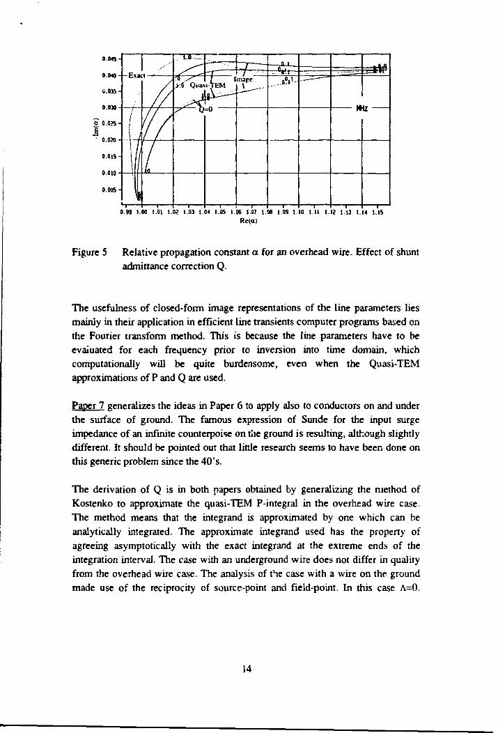
Figure 5 gives a view of the accuracy of the approximations within the frequencyrange 0.01-10 MHz for a special case with h=10 m and a=0.01 m for the wire, andtf=lQ, and <r=1000 torn for ground. The quantity a is the relative propagationconstant of the wire defined by Yw=otY0- The imaginary part of a is a measure ofthe attenuation. The reciprocal of the real part is the phase velocity relative tolight. The effect of including Q is seen to be significant for frequencies above 0.1MHz in that the attenuation characteristic is markedly modified, and that phasevelocities greater than light velocity are resulting. A very much analogousanalysis for the characteristic impedance of the wire is contained in the paper.
13
0.045
0.040
C.035
0.030
ö 0.035
I- o.o»
0.015
0.010
0.005
1J
0.99 1.00 1.01 1.02 1.03 1.04 1.05 1.06 1.07 1.06 1.09 1 10 1.11 1.12 1.13 1.14 1.15Rc(ct)
Figure 5 Relative propagation constant a for an overhead wire. Effect of shuntadmittance correction Q.
The usefulness of closed-form image representations of the line parameters liesmainly in their application in efficient line transients computer programs based onthe Fourier transform method. This is because the line parameters have to beevaluated for each frequency prior to inversion into time domain, whichcomputationally will be quite burdensome, even when the Quasi-TEMapproximations of P and Q are used.
Paper 7 generalizes the ideas in Paper 6 to apply also to conductors on and underthe surface of ground. The famous expression of Sunde for the input surgeimpedance of an infinite counterpoise on the ground is resulting, although slightlydifferent. It should be pointed out that little research seems to have been done onthis generic problem since the 40's.
The derivation of Q is in both papers obtained by generalizing the method ofKostenko to approximate the quasi-TEM P-integral in the overhead wire case.The method means that the integrand is approximated by one which can beanalytically integrated. The approximate integrand used has the property ofagreeing asymptotically with the exact integrand at the extreme ends of theintegration interval. The case with an underground wire does not differ in qualityfrom the overhead wire case. The analysis of the case with a wire on the groundmade use of the reciprocity of source-point and field-point. In this case A=0.
14
Further, Yw=[( YQ+Yg)/2] "• is inserted into the right hand side of the modal equation,were yK is the intrinsic propagation constant of the ground.
Both papers actually consider mutual coupling of two wires. The expressions forP and Q will then be slightly more complex than indicated above for the self-coupling case. Knowledge of the mutual couplings between all pairs ofconductors is necessary and sufficient for assessing all the possible propagationmodes for waves on a multi-conductor transmission line. The validity of the Q-approximation remains to be tested for the general case.
6. SUMMARY
The objective of the thesis is to show the feasibility of establishing closed-formapproximate but still accurate solutions to many of the basic problemsencountered in estimating lightning performance of transmission lines. It has beendemonstrated that such an approach is fruitful and that little accuracy may be lostcompared to when numerical methods are used. Actually, it may even be that theanalytical solution is exact up to the problem formulation.
It is shown that lightning incidence to lines, and also to tower-type objects, whenthe classical electrogeometric model of lightning attraction is used together withthe log-normal probability distribution for lightning currents, can be convenientlyrepresented in closed form. Expressions are given for the number of hits and thebias in distribution of the currents collected as compared to those to flat ground.
Using the concept of attractive zone width, the outage rate from shielding failureflashovers and back-flashovers can be analysed in a unified way, assuming thatthe critical current for flashover is given. The approximate solutions involve thestandardized normal distribution function.
System response to lightning strikes is analysed by use of Laplace transformscombined with transmission-line theory. Inversion into time domain is achievedby an asymptotic method producing closed-form results. The back-flashoverproblem is analysed in particular.
Finally the general problem of propagation of high-frequency transients on wiresabove, on and under ground is addressed. An image-type representation of theshunt capacitance correction term is derived. The derivation parallels that for theseries effects, the "complex depth" approximation.
15
REFERENCES
[1] IEEE Working Group Report, "Estimating Lightning Performance ofTransmission Lines II - Updates on Analytical Models", IEEE Trans.Paper No. 92 SM 453-1 PWRD presented at the IEEE Summer PowerMeeting, Seattle, Washington, USA, July 1992
[2] CIGRÉ Working Group 33.01, "Guide to Procedures for Estimating theLightning Performance of Transmission Lines", CIGRÉ Monograph No.63, October 1991
[3] Per Pettersson, Roland Eriksson, "Insulation Optimization of a SwedishUrban Area Line", Proc. CIGRÉ Symposium on Compacting OverheadLines, Leningrad, USSR, Paper No. 400-01, June 1991.
16


![WORLD MEETING ON LIGHTNING 2016 Lightning Performance ... · 4] Anderson J. G. "Monte Carlo Computer Calculation of Transmission-Line Lightning Performance". AIEE Trans. Vol. 80,](https://img.pdfslide.us/doc/110x75/5eb98b41dd23427e6a596ebb/world-meeting-on-lightning-2016-lightning-performance-4-anderson-j-g-monte.jpg)