Embed Size (px)
Citation preview
All India Radio (AIR)
FM Station Dharamshala.
Presented by:
Anuradha
Jv-i/11/4336
B.Tech(ec)-M.Tech(ec)

Radio is the transmission of
signals by Modulation of
electromagnetic waves with
frequencies below those of visible light
Radio is based on wireless
communication or satellite
communication.
In this era of technology due to the need of the
wireless communication, a National service was
planned and developed by the Prasar Bharti
broadcasting corporation of India

• For 75 years, all India radio is one of the largest radio networks in the world. AIR,
reaches the remotest corners of the country.
• All India Radio (abbreviated as AIR), officially known as Akashvani is the radio
broadcaster of India and a division of Prasar Bharati . the headquarters is at the
Akashvani Bhavan, New Delhi.
• Today air has a network of 213 broadcasting centres covering 90% of the area & almost
reaching the entire population of one billion.
• The external services division of all India radio broadcasts in 27 languages to countries
outside of India.

• AIR DHARAMSHALA :
COMMISSIONED ON
23RD FEBRUARY, 1994.
• FM BROADCASTING
STATION.
• FREQUENCY : 103.4MHZ.
IMPORTANT DATA ABOUT AIR
(DHARAMSHALA)
• Transmitter :2x5 kW FM VHF transmitter ( HVB 165/A)
coverage area : 60-80km (in air)
• Height of tower : 100m.
FM transmitting antenna height : 82m
• dipoles used for transmission : six
Distance between each dipole: 2.6m
• Along with the transmission of program from Dharamshala
studio, it also relays some of the program from FM rainbow
(Delhi), Vividh Bharti (AIR Mumbai), AIR Delhi and AIR
Shimla.

Transmission-A radio wave carries
information; signals are converted
into electrical signals. A carrier
wave is then produced from the
modulation .The wave is then
amplified and sent to the antenna
that then converts signal into an
E.M. Wave.
Reception- An
antenna on
receiving the
signal send it to
the receiver this
converts the
electrical signal,
sends it to the
amplifier either a
speaker
/headphones jack,
this is then
converted into a
sound wave.

RADIO BROADCASTING –
Radio broadcasting is the one way wireless transmission over radio waves intended
to reach wide audience .
TYPES OF RADIO BROADCASTING –
AM ( Amplitude Modulation )
FM ( Frequency Modulation )
How radio electromagnetic waves changes to radio waves
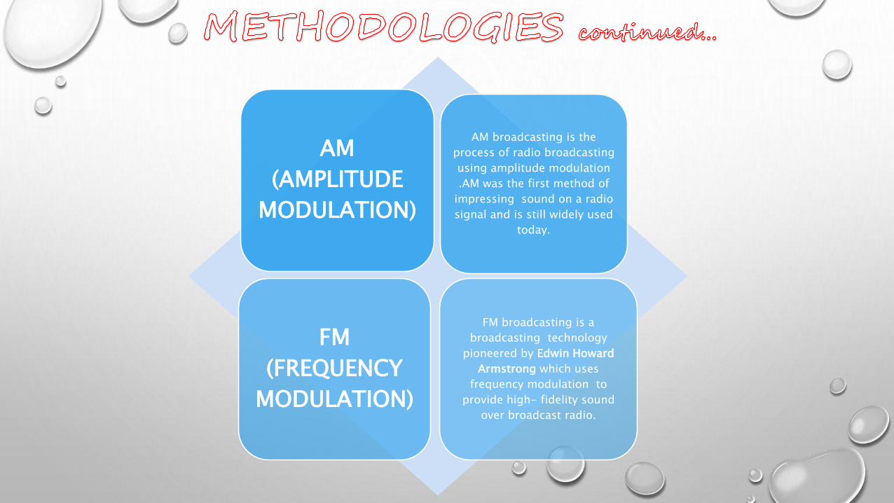
AM
(AMPLITUDE
MODULATION)
AM broadcasting is the
process of radio broadcasting
using amplitude modulation
.AM was the first method of
impressing sound on a radio
signal and is still widely used
today.
FM
(FREQUENCY
MODULATION)
FM broadcasting is a
broadcasting technology
pioneered by Edwin Howard
Armstrong which uses
frequency modulation to
provide high- fidelity sound
over broadcast radio.
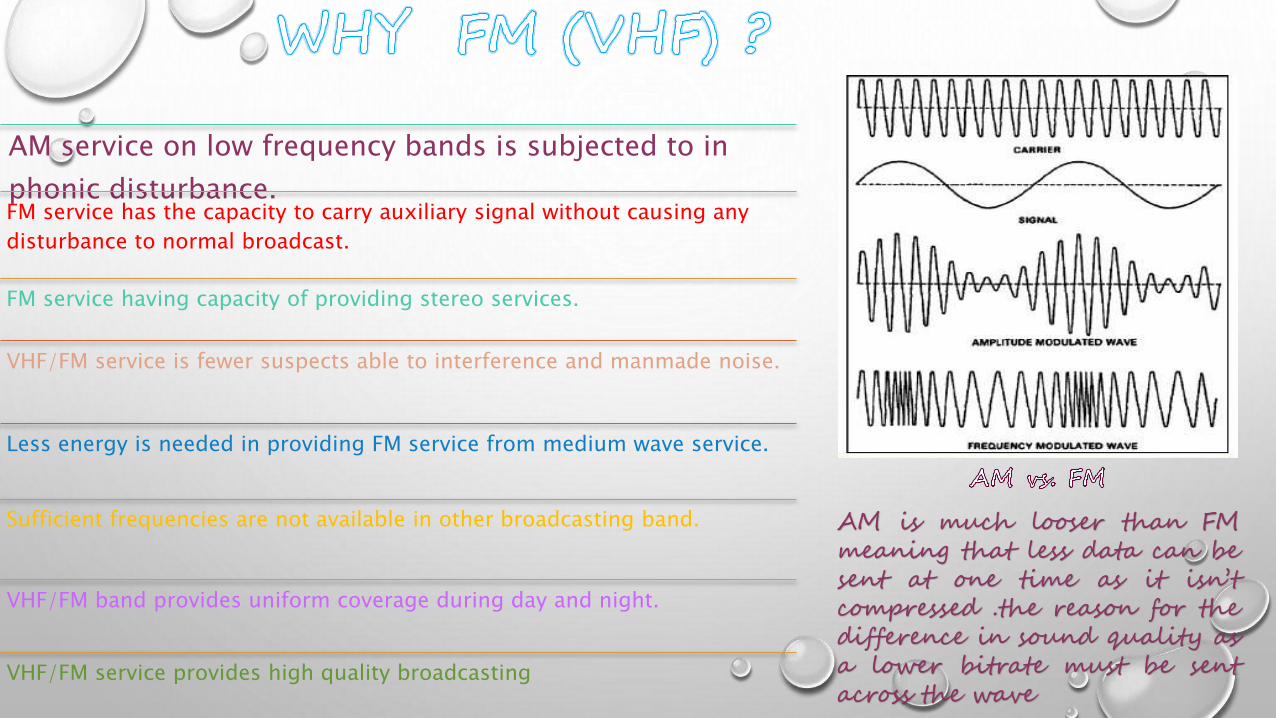
AM service on low frequency bands is subjected to in
phonic disturbance.FM service has the capacity to carry auxiliary signal without causing any
disturbance to normal broadcast.
FM service having capacity of providing stereo services.
VHF/FM service is fewer suspects able to interference and manmade noise.
Less energy is needed in providing FM service from medium wave service.
Sufficient frequencies are not available in other broadcasting band.
VHF/FM band provides uniform coverage during day and night.
VHF/FM service provides high quality broadcasting
AM is much looser than FMmeaning that less data can besent at one time as it isn’tcompressed .the reason for thedifference in sound quality asa lower bitrate must be sentacross the wave
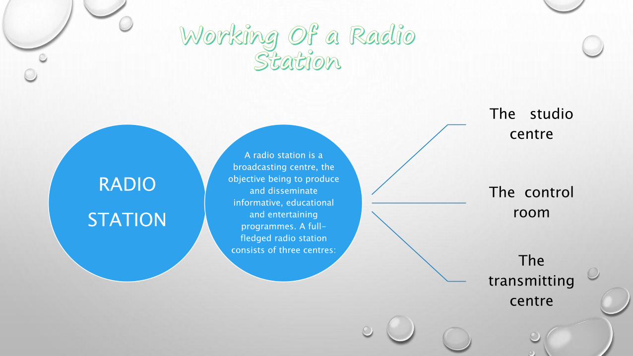
RADIO
STATION
A radio station is a
broadcasting centre, the
objective being to produce
and disseminate
informative, educational
and entertaining
programmes. A full-
fledged radio station
consists of three centres:
The studio
centre
The control
room
The
transmitting
centre

Thus broadcasting chain involves these two chains:
Studio to control roomControl to transmitter room
(transmission)
BROADCASTING CHAIN - it consists of studios, receiving centre and
transmitter. Studio-It consists of several studios,
designed to meet the special
requirements of broadcasting and a
control room. A microphone is provided
in each studio. The microphone picks
up voice signals and converts these into
electrical signals.
Control room -these electrical
signals are amplified and passed on
to control room and it selects the
studio according to the queue sheet
(time schedule) of various
broadcasts and controls the level of
program.
Transmitter -
these are than
feed to the
transmitter which
radiates the
modulated R.F.
Signal.
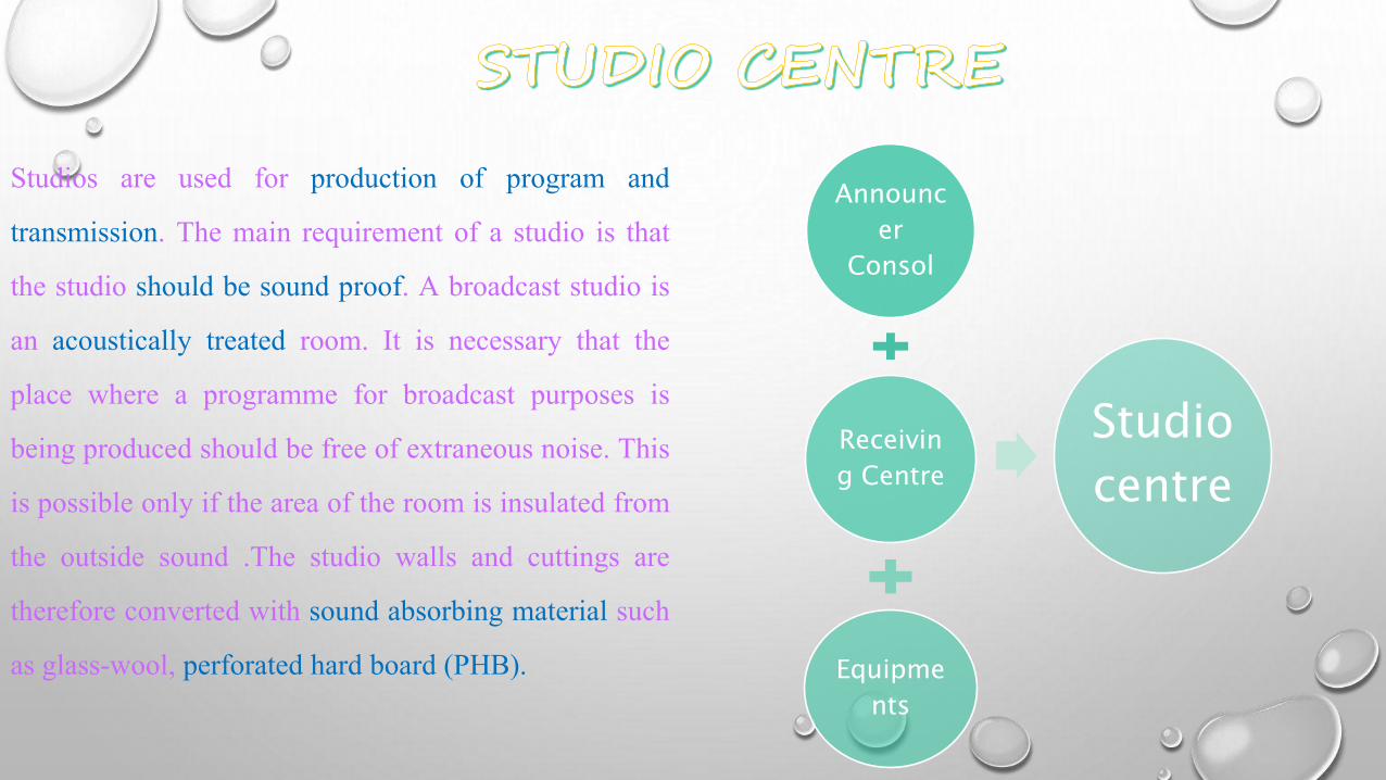
Studios are used for production of program and
transmission. The main requirement of a studio is that
the studio should be sound proof. A broadcast studio is
an acoustically treated room. It is necessary that the
place where a programme for broadcast purposes is
being produced should be free of extraneous noise. This
is possible only if the area of the room is insulated from
the outside sound .The studio walls and cuttings are
therefore converted with sound absorbing material such
as glass-wool, perforated hard board (PHB).
Announc
er
Consol
Receivin
g Centre
Equipme
nts
Studio
centre

PRE-AMPLIFIER
60db
PAD
-10db
FADE
R
-10
db
AUDIO DISTRIBUTI
-ONAMPLIFIER
+10db
MIXER
FADE
R
-10
db
AUDIO DISTRIBUTI-
ONAMPLIFIER
+10db
MIXER
LINEAMP-14db
MIKE -10db
-70db -20 -10 -20 -10db db db db +4 db
Equipment
0dbm
(1mW)

FADER
-10db
ADA
+10db
MASTERFADER
-10db
ADA
+10dbLIMITER
TRANS
-MITTER
+4
db-6db +4db
-6db +4db -6db
The block diagram shows that it
consist of limiter, exciter, power
amplifier, power coupler or divider,
harmonic filters and a monitoring and
combining rack which is connected to
the transmission antenna.
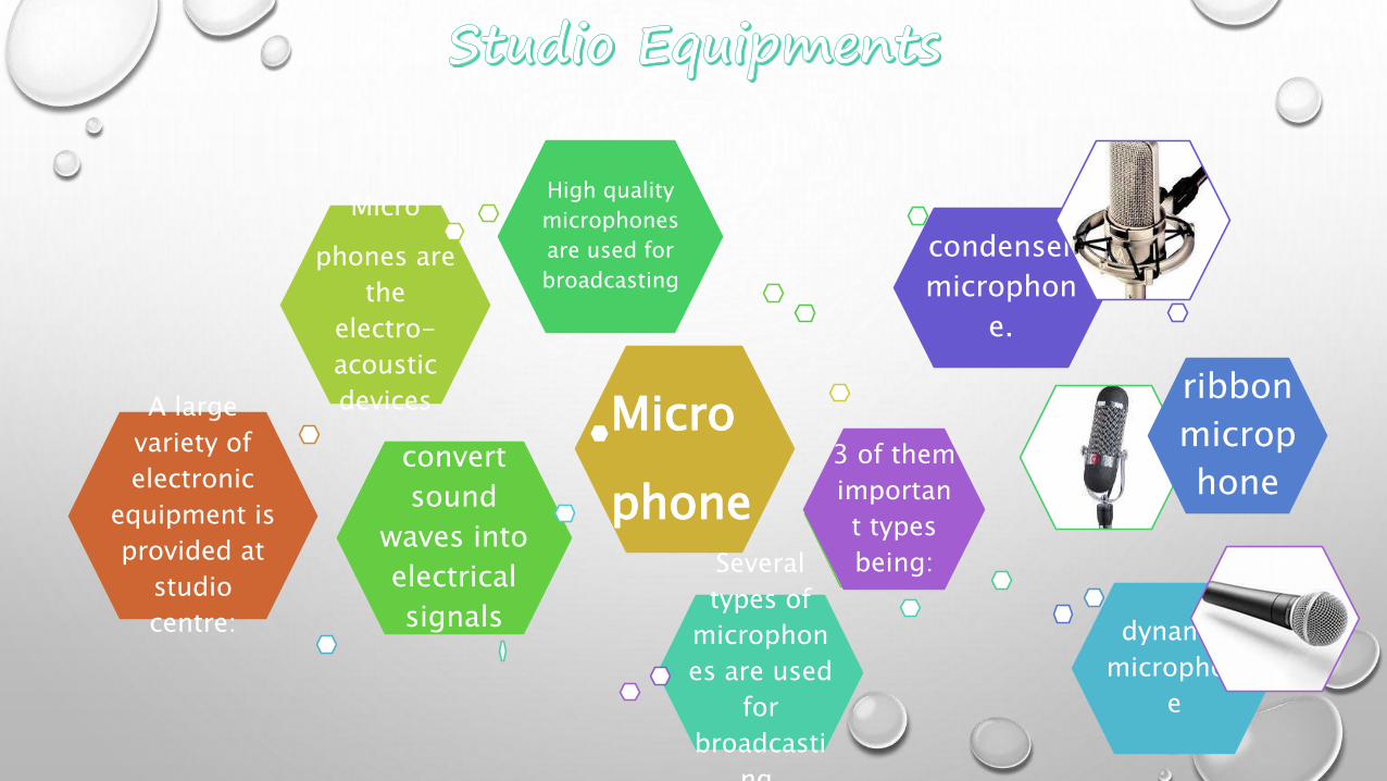
A large
variety of
electronic
equipment is
provided at
studio
centre:
Micro
phone
Micro
phones are
the
electro-
acoustic
devices
convert
sound
waves into
electrical
signals
High quality
microphones
are used for
broadcasting
Several
types of
microphon
es are used
for
broadcasti
ng,
dynamic
microphon
e
ribbon
microp
hone
condenser
microphon
e.
3 of them
importan
t types
being:

Amplifiers are
electronic
devices, which
amplify the
signals. The
electrical
signals
obtained from
a microphone
(or other low
level source
such as pick
up or playback
head) are very
weak. The
power of these
signals has to
be increased
(amplified)
before these
can be utilized.
Four
types of
amplifie
rs are
commo
nly used
in
studios:
Preamplifier-
The first
amplifier in
the broadcast
chain. The
output from a
microphone
are a pickup
which is at a
very low level.
The pre-
amplifier has
a gain of
about 60db. A
special
feature of
these
amplifiers is
that their
contributed
Program
Amplifier-
These provide
second stage
noise of
amplification.
The O/P
obtained from
the feeder
box (or
mixing
console) is
fed to the
input of these
amplifiers.
The gain of
this amplifier
is around
40db.
Monitoring
Amplifier -The
O/P available
from program
amplifier is not
enough to drive
loud speakers.
Monitoring
amplifiers are
provided to
boost the signals
further. A
separate
monitoring
amplifier is used
for a group of
loudspeakers
which are located
in studios,
control room,
duty room and
other selected
places for
continuous
monitoring of
Line equalized
Amplifier-the
programs are
fed from the
studio to the
transmitter;
there is
considerable
loss during
this
processing. So,
to equalize the
losses, line
equalisers are
used. Equalizer
line amplifiers
have the
provision for
adjusting the
gain and
frequency

These are variable alternators having constant input and output impedance. The faders are
provided in their fader box in the transmission booth. These are used for fading in and out
the program and combining the program. No. Of faders in the fader box corresponds to the
no. Of sound sources in the booth. The level of the program being fed to the transmitter has
to be controlled. Faders are provided for this purpose.
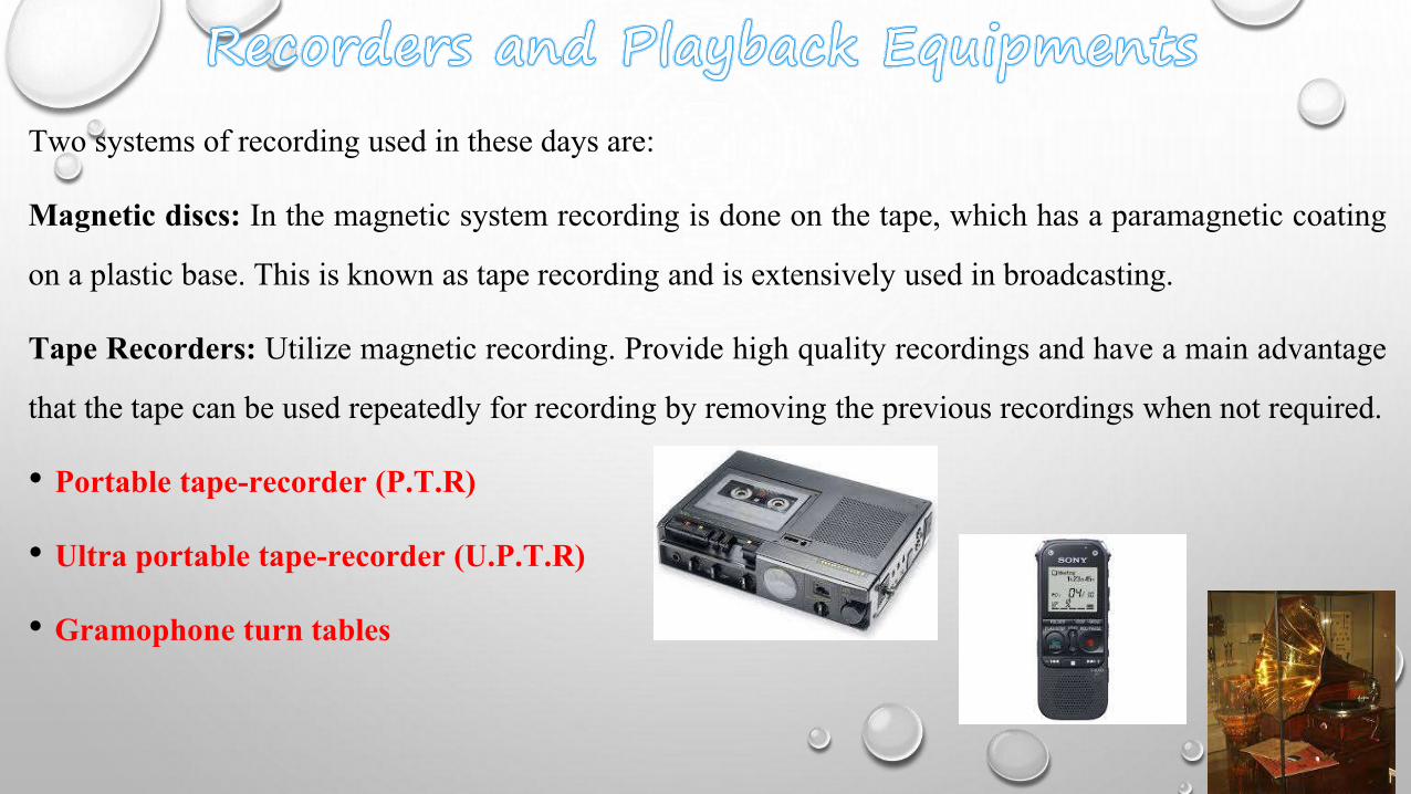
Two systems of recording used in these days are:
Magnetic discs: In the magnetic system recording is done on the tape, which has a paramagnetic coating
on a plastic base. This is known as tape recording and is extensively used in broadcasting.
Tape Recorders: Utilize magnetic recording. Provide high quality recordings and have a main advantage
that the tape can be used repeatedly for recording by removing the previous recordings when not required.
• Portable tape-recorder (P.T.R)
• Ultra portable tape-recorder (U.P.T.R)
• Gramophone turn tables
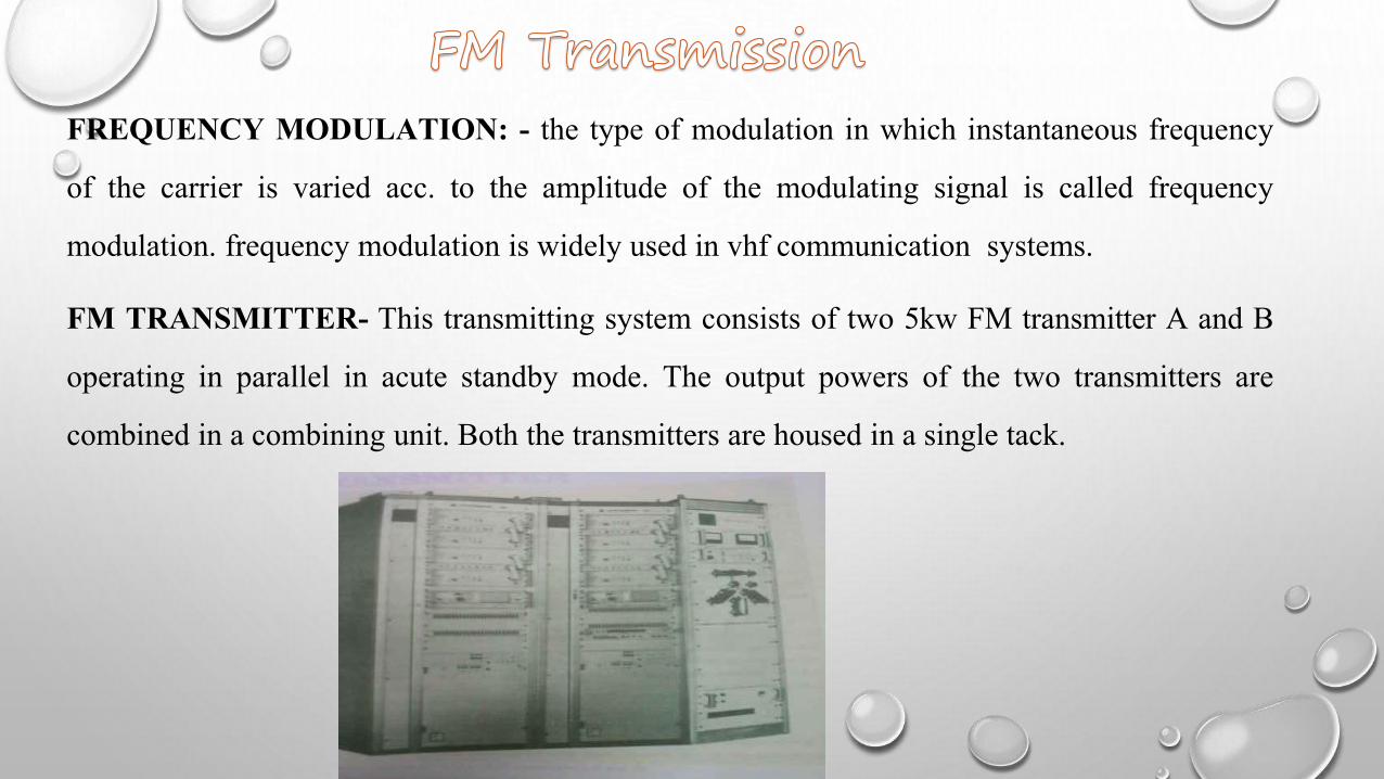
FREQUENCY MODULATION: - the type of modulation in which instantaneous frequency
of the carrier is varied acc. to the amplitude of the modulating signal is called frequency
modulation. frequency modulation is widely used in vhf communication systems.
FM TRANSMITTER- This transmitting system consists of two 5kw FM transmitter A and B
operating in parallel in acute standby mode. The output powers of the two transmitters are
combined in a combining unit. Both the transmitters are housed in a single tack.
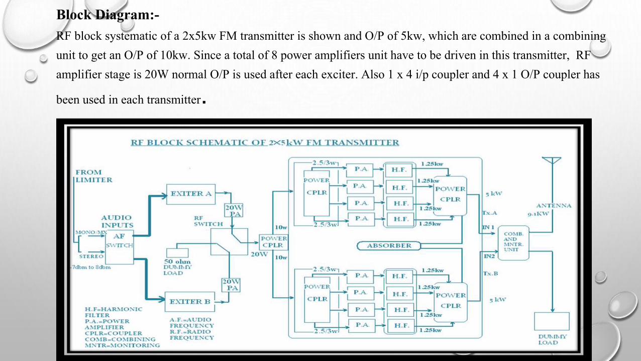
Block Diagram:-
RF block systematic of a 2x5kw FM transmitter is shown and O/P of 5kw, which are combined in a combining
unit to get an O/P of 10kw. Since a total of 8 power amplifiers unit have to be driven in this transmitter, RF
amplifier stage is 20W normal O/P is used after each exciter. Also 1 x 4 i/p coupler and 4 x 1 O/P coupler has
been used in each transmitter.
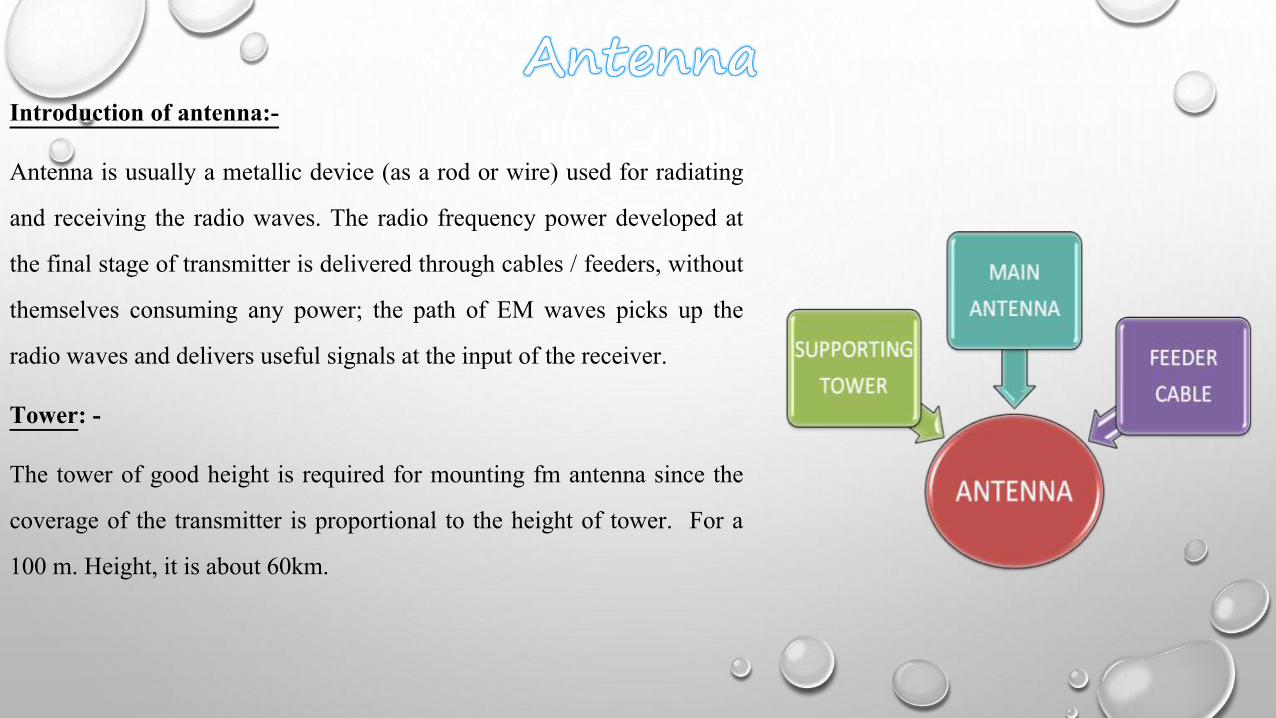
Introduction of antenna:-
Antenna is usually a metallic device (as a rod or wire) used for radiating
and receiving the radio waves. The radio frequency power developed at
the final stage of transmitter is delivered through cables / feeders, without
themselves consuming any power; the path of EM waves picks up the
radio waves and delivers useful signals at the input of the receiver.
Tower: -
The tower of good height is required for mounting fm antenna since the
coverage of the transmitter is proportional to the height of tower. For a
100 m. Height, it is about 60km.
• Wide band usage from 88-108 MHz range.
• Omni directional horizontal pattern of field strength.
• Circular polarization for better reception.
• High gain for both vertical & horizontal signals.
• Sturdy design for maintenance free service.
• FM antenna at 82m. Height.
• TV antenna at 65 m. Height.
• Climbing ladder with cage up of 82 m. Height & free fall prevention system above this.
• Cable tray for mounting the rf feeder, mast light, power supply at each platform.
• The tower has been designed on the basis of latest wind speed specification issued by BSNL.

• A universal medium. Can be enjoyed at home, at work, and while driving. Most people listen to the
radio at one time or another during the day.
• This is the only means which can provide multi access two way communication.
• The cost of transmitting information through satellite is independent of distance involved
• Satellite can be used for two way communication or broadcast purpose with the covered area.
• Satellites are capable of handling very high bandwidth.
• It is possible to provide large coverage using satellite.
• Free creative help is usually available.

• Only an audio medium.
• Not as fast as using a phone or internet; could take a little bit.
• Radio is a background medium. Most listeners are doing something else while
listening, which means your ad has to work hard to be listened to and
understood.
• The line could get fuzzy, or not clear.