Embed Size (px)
Citation preview

Making the Transition:
Hosted by
Andrew Hudak Fictiv
and
Brett Swope Swope Design Solutions
3D Printing to CNC Machining

Your Hosts
Andrew Hudak
● Founder & Principal Engineer@ Swope Design Solutions
● M.S.M.E. Stanford University● B.S.M.E. Clemson University
● Prototyping Engineer @ Fictiv
● M.S.M.E. Stanford University● B.S.M.E. University of Portland
Brett Swope
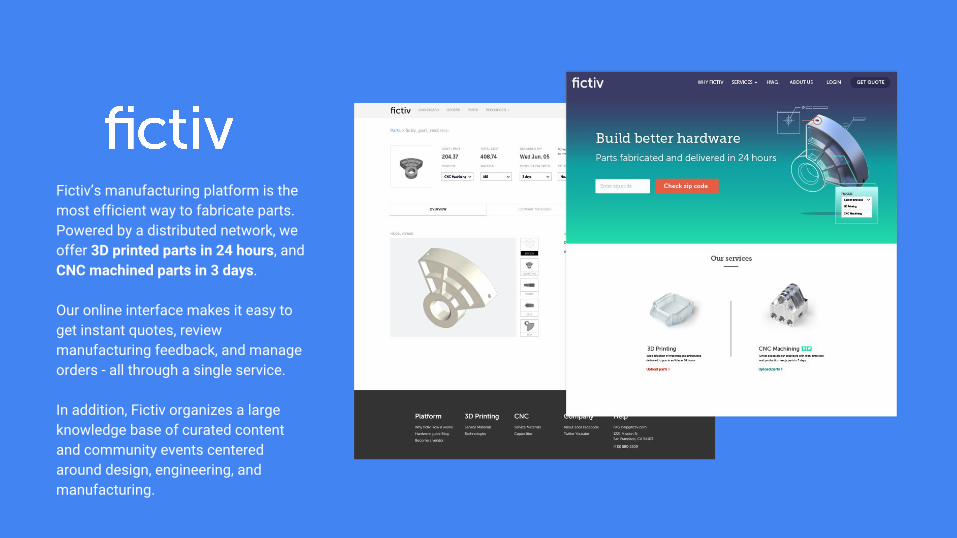
Fictiv’s manufacturing platform is the most efficient way to fabricate parts. Powered by a distributed network, we offer 3D printed parts in 24 hours, and CNC machined parts in 3 days.
Our online interface makes it easy to get instant quotes, review manufacturing feedback, and manage orders - all through a single service.
In addition, Fictiv organizes a large knowledge base of curated content and community events centered around design, engineering, and manufacturing.
Consumer products
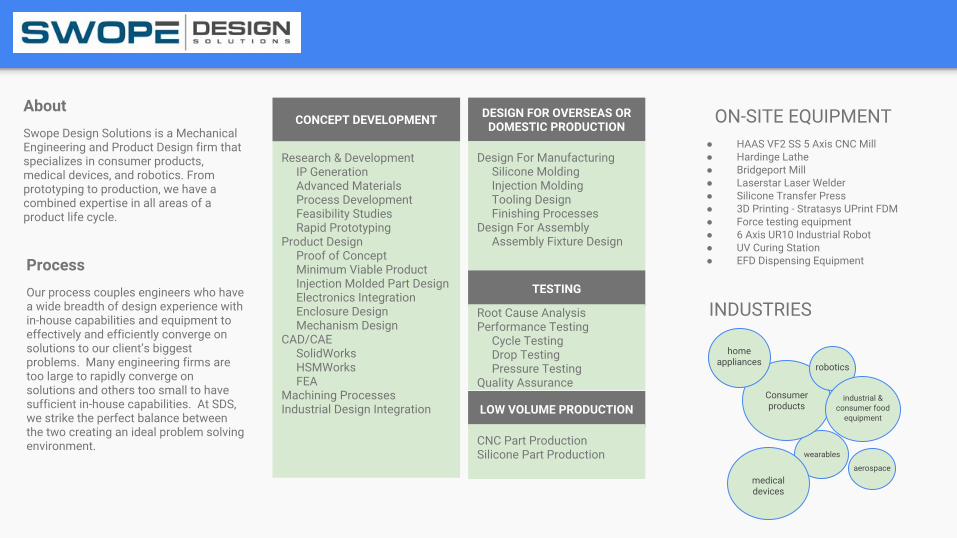
Research & Development IP Generation Advanced Materials Process Development Feasibility Studies Rapid PrototypingProduct Design Proof of Concept Minimum Viable Product Injection Molded Part Design Electronics Integration Enclosure Design Mechanism DesignCAD/CAE SolidWorks HSMWorks FEAMachining ProcessesIndustrial Design Integration
AboutSwope Design Solutions is a Mechanical Engineering and Product Design firm that specializes in consumer products, medical devices, and robotics. From prototyping to production, we have a combined expertise in all areas of a product life cycle.
ProcessOur process couples engineers who have a wide breadth of design experience with in-house capabilities and equipment to effectively and efficiently converge on solutions to our client’s biggest problems. Many engineering firms are too large to rapidly converge on solutions and others too small to have sufficient in-house capabilities. At SDS, we strike the perfect balance between the two creating an ideal problem solving environment.
DESIGN FOR OVERSEAS OR DOMESTIC PRODUCTION
Design For Manufacturing Silicone Molding Injection Molding Tooling Design Finishing ProcessesDesign For Assembly Assembly Fixture Design
TESTING
Root Cause AnalysisPerformance Testing Cycle Testing Drop Testing Pressure TestingQuality Assurance
LOW VOLUME PRODUCTION
CNC Part ProductionSilicone Part Production
● HAAS VF2 SS 5 Axis CNC Mill● Hardinge Lathe● Bridgeport Mill● Laserstar Laser Welder● Silicone Transfer Press● 3D Printing - Stratasys UPrint FDM● Force testing equipment● 6 Axis UR10 Industrial Robot● UV Curing Station● EFD Dispensing Equipment
ON-SITE EQUIPMENT
home appliances robotics
industrial & consumer food
equipment
medical devices
wearables
aerospace
INDUSTRIES
CONCEPT DEVELOPMENT

Overview
● What is CNC Machining?
● CNC in the PD cycle / When to Transition
● Communicating Design Intent
● Design Considerations & Pitfalls
● Machine Planning & Programming
● Question & Answer
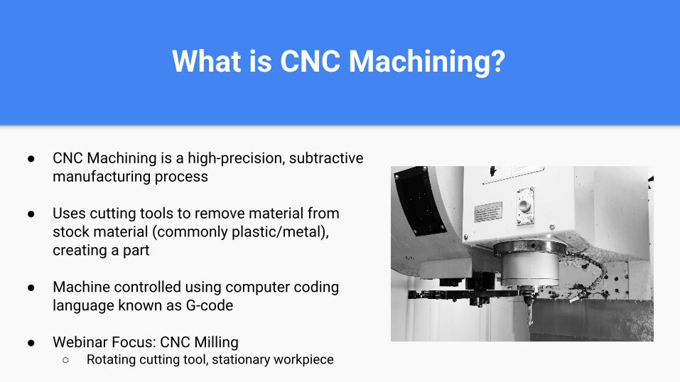
What is CNC Machining?
● CNC Machining is a high-precision, subtractive manufacturing process
● Uses cutting tools to remove material from stock material (commonly plastic/metal), creating a part
● Machine controlled using computer coding language known as G-code
● Webinar Focus: CNC Milling○ Rotating cutting tool, stationary workpiece
CNC in the PD CycleWhen to Transition

When to Transition to CNC
All prototypes are built to answer questions. When you need to address questions that no longer make sense being answered using 3D printing, it is time to transition to CNC machining in the PD cycle. Some examples include:
● Designs that require mechanical or physical properties not available with 3DP materials
Living Hinges Testing and documentation for regulatory bodies
Prototypes for user testing with safety implications (food contact, etc)
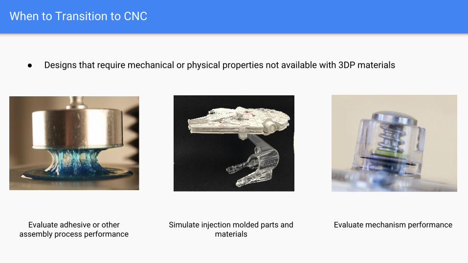
When to Transition to CNC
● Designs that require mechanical or physical properties not available with 3DP materials
Evaluate adhesive or other assembly process performance
Simulate injection molded parts and materials
Evaluate mechanism performance
When to Transition to CNC
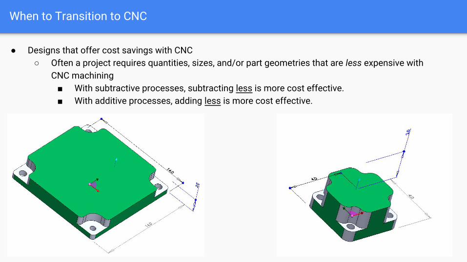
● Designs that offer cost savings with CNC○ Often a project requires quantities, sizes, and/or part geometries that are less expensive with
CNC machining■ With subtractive processes, subtracting less is more cost effective.■ With additive processes, adding less is more cost effective.

Communicating Design Intent
Communicating Design Intent
Whether or not you are working directly with a machinist, efficiently expressing the most critical aspects of your design is especially important. Overall things to keep in mind: ● Certain features are more important than others; prioritize them● Communicating intent in your design will save time, money, and confusion● Additional documentation/clarity is never a bad idea and in some cases is
required
Communicating Design Intent - Hole Tapping
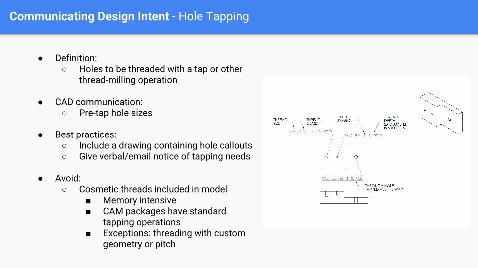
● Definition: ○ Holes to be threaded with a tap or other
thread-milling operation
● CAD communication: ○ Pre-tap hole sizes
● Best practices: ○ Include a drawing containing hole callouts ○ Give verbal/email notice of tapping needs
● Avoid: ○ Cosmetic threads included in model
■ Memory intensive■ CAM packages have standard
tapping operations■ Exceptions: threading with custom
geometry or pitch
Communicating Design Intent - Mating Parts
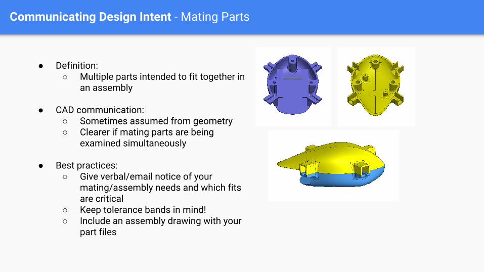
● Definition: ○ Multiple parts intended to fit together in
an assembly
● CAD communication: ○ Sometimes assumed from geometry○ Clearer if mating parts are being
examined simultaneously
● Best practices: ○ Give verbal/email notice of your
mating/assembly needs and which fits are critical
○ Keep tolerance bands in mind!○ Include an assembly drawing with your
part files
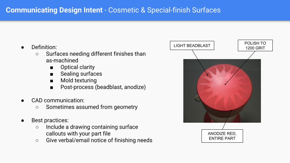
Communicating Design Intent - Cosmetic & Special-finish Surfaces
● Definition: ○ Surfaces needing different finishes than
as-machined■ Optical clarity■ Sealing surfaces■ Mold texturing■ Post-process (beadblast, anodize)
● CAD communication:○ Sometimes assumed from geometry
● Best practices: ○ Include a drawing containing surface
callouts with your part file○ Give verbal/email notice of finishing needs
POLISH TO 1200 GRITLIGHT BEADBLAST
ANODIZE RED, ENTIRE PART
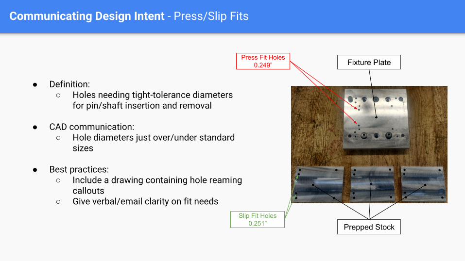
Communicating Design Intent - Press/Slip Fits
● Definition: ○ Holes needing tight-tolerance diameters
for pin/shaft insertion and removal
● CAD communication:○ Hole diameters just over/under standard
sizes
● Best practices: ○ Include a drawing containing hole reaming
callouts○ Give verbal/email clarity on fit needs
Fixture Plate
Prepped Stock
Press Fit Holes0.249”
Slip Fit Holes0.251”
Design Considerations & Pitfalls
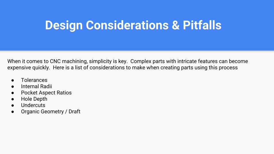
Design Considerations & Pitfalls
When it comes to CNC machining, simplicity is key. Complex parts with intricate features can become expensive quickly. Here is a list of considerations to make when creating parts using this process
● Tolerances● Internal Radii● Pocket Aspect Ratios● Hole Depth● Undercuts● Organic Geometry / Draft
Design Considerations & Pitfalls - Tolerances
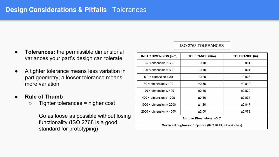
● Tolerances: the permissible dimensional variances your part’s design can tolerate
● A tighter tolerance means less variation in part geometry; a looser tolerance means more variation
● Rule of Thumb○ Tighter tolerances = higher cost
Go as loose as possible without losing functionality (ISO 2768 is a good standard for prototyping)
ISO 2768 TOLERANCES
Design Considerations & Pitfalls - Internal Radii
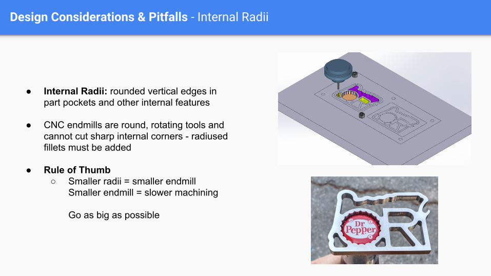
● Internal Radii: rounded vertical edges in part pockets and other internal features
● CNC endmills are round, rotating tools and cannot cut sharp internal corners - radiused fillets must be added
● Rule of Thumb○ Smaller radii = smaller endmill
Smaller endmill = slower machining
Go as big as possible
Design Considerations & Pitfalls - Pocket Aspect Ratios
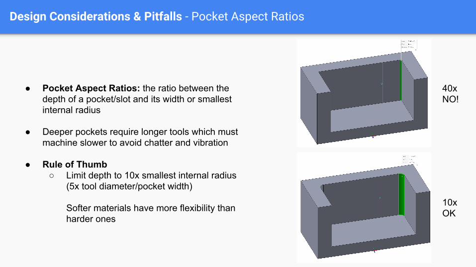
● Pocket Aspect Ratios: the ratio between the depth of a pocket/slot and its width or smallest internal radius
● Deeper pockets require longer tools which must machine slower to avoid chatter and vibration
● Rule of Thumb○ Limit depth to 10x smallest internal radius
(5x tool diameter/pocket width)
Softer materials have more flexibility than harder ones
40xNO!
10xOK
Design Considerations & Pitfalls - Hole Depth
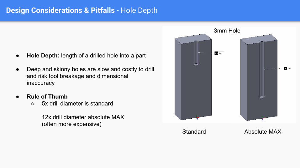
● Hole Depth: length of a drilled hole into a part
● Deep and skinny holes are slow and costly to drill and risk tool breakage and dimensional inaccuracy
● Rule of Thumb○ 5x drill diameter is standard
12x drill diameter absolute MAX(often more expensive)
Standard Absolute MAX
3mm Hole

Design Considerations & Pitfalls - Undercuts
● Undercuts: Features only possible to create by milling underneath overhanging material
● Require special milling tools that may cost extra depending on feature geometry
● Rule of Thumb○ Avoid whenever possible
For o-ring grooves and keyways, stick to standard geometries
Design Considerations & Pitfalls - Organic Geometry / Draft
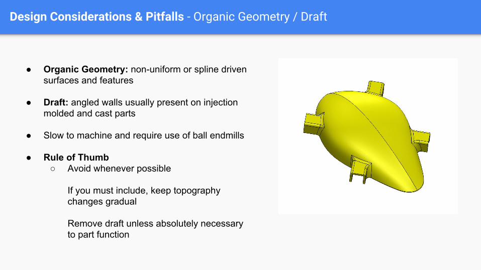
● Organic Geometry: non-uniform or spline driven surfaces and features
● Draft: angled walls usually present on injection molded and cast parts
● Slow to machine and require use of ball endmills
● Rule of Thumb○ Avoid whenever possible
If you must include, keep topography changes gradual
Remove draft unless absolutely necessary to part function

Machine Planning & Programming
Machine Planning and Programming
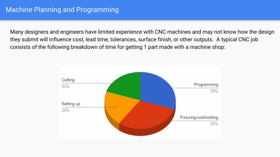
Many designers and engineers have limited experience with CNC machines and may not know how the design they submit will influence cost, lead time, tolerances, surface finish, or other outputs. A typical CNC job consists of the following breakdown of time for getting 1 part made with a machine shop:
Machine Planning and Programming
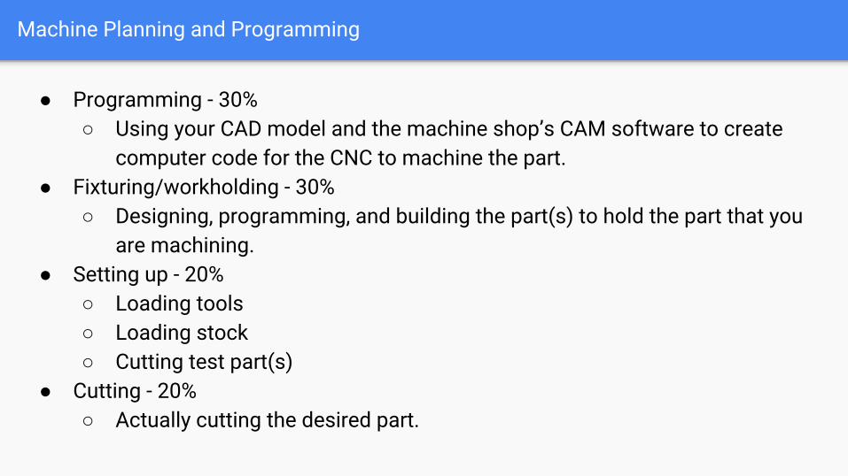
● Programming - 30%○ Using your CAD model and the machine shop’s CAM software to create
computer code for the CNC to machine the part.● Fixturing/workholding - 30%
○ Designing, programming, and building the part(s) to hold the part that you are machining.
● Setting up - 20%○ Loading tools○ Loading stock○ Cutting test part(s)
● Cutting - 20%○ Actually cutting the desired part.
Machine Planning and Programming
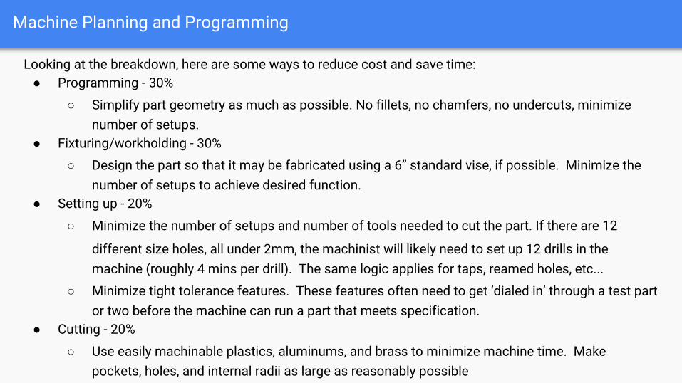
Looking at the breakdown, here are some ways to reduce cost and save time:● Programming - 30%
○ Simplify part geometry as much as possible. No fillets, no chamfers, no undercuts, minimize number of setups.
● Fixturing/workholding - 30%
○ Design the part so that it may be fabricated using a 6” standard vise, if possible. Minimize the number of setups to achieve desired function.
● Setting up - 20%
○ Minimize the number of setups and number of tools needed to cut the part. If there are 12
different size holes, all under 2mm, the machinist will likely need to set up 12 drills in the machine (roughly 4 mins per drill). The same logic applies for taps, reamed holes, etc...
○ Minimize tight tolerance features. These features often need to get ‘dialed in’ through a test part or two before the machine can run a part that meets specification.
● Cutting - 20%
○ Use easily machinable plastics, aluminums, and brass to minimize machine time. Make pockets, holes, and internal radii as large as reasonably possible
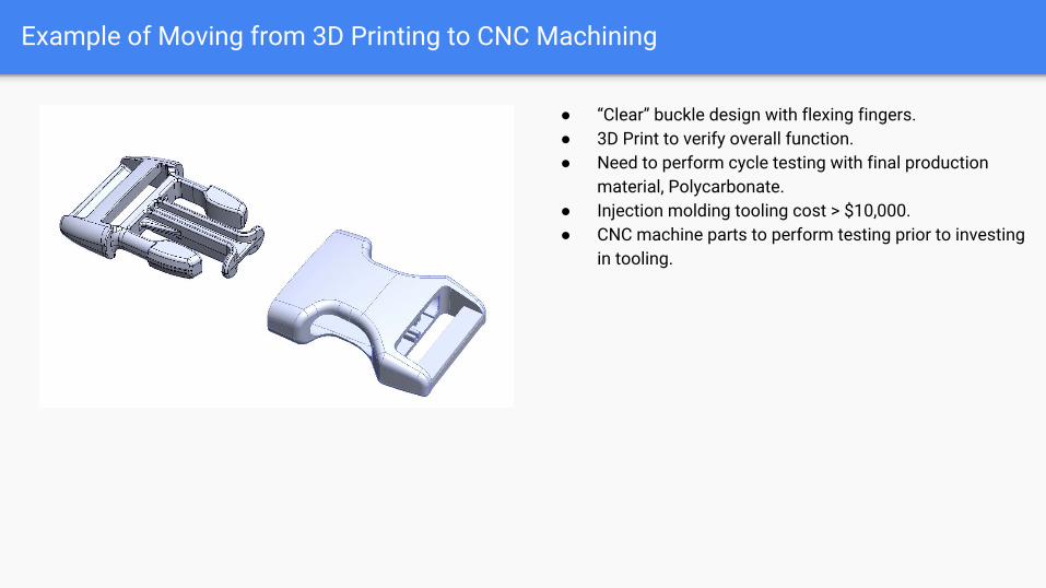
Example of Moving from 3D Printing to CNC Machining
● “Clear” buckle design with flexing fingers.● 3D Print to verify overall function.● Need to perform cycle testing with final production
material, Polycarbonate.● Injection molding tooling cost > $10,000.● CNC machine parts to perform testing prior to investing
in tooling.
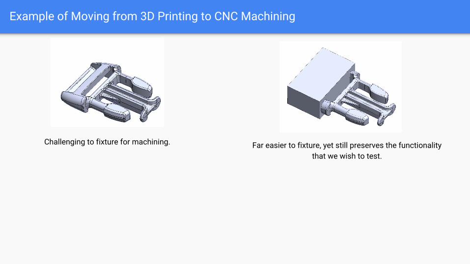
Example of Moving from 3D Printing to CNC Machining
Challenging to fixture for machining. Far easier to fixture, yet still preserves the functionality that we wish to test.
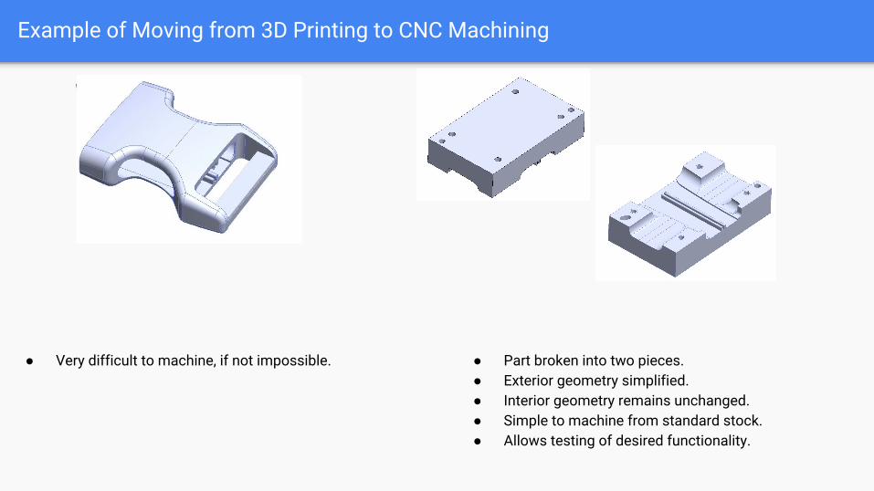
Example of Moving from 3D Printing to CNC Machining
● Very difficult to machine, if not impossible. ● Part broken into two pieces.● Exterior geometry simplified.● Interior geometry remains unchanged.● Simple to machine from standard stock.● Allows testing of desired functionality.

Question & Answer

Go to fictiv.com/champion & use code:
Thanks For Listening!
To get 20% off your order
CNCWEBINAR