Embed Size (px)
Citation preview
International Journal of Advanced Engineering Research and Science (IJAERS) [Vol-2, Issue-7, JULY- 2015]
ISSN: 2349-6495
Page | 86
Systematic Design and Analysis of Straight Bevel Gears in Right-Angle Drive Transmission
Applications Joseph T. Osewere, Tonye K. Jack, Harold U. Nwosu
Department of Mechanical Engineering, University of Port-Harcourt, Port-Harcourt, Nigeria
Abstract— What sets the basis for a sturdy, durable, quiet, and sustainable bevel gear pair torque transmission application? And, which of the engineering concerns of strength and wear governs the choice of gear material(s) for optimum performance? That lies in the nexus between the bevel gears sizing design, and detailed analysis for adequacy of withstanding the static and dynamic loadings, and satisfying the conditions that prevent premature tooth fracture, and surface wear. In this paper a computational interactive tool for conservative design and analysis of standard straight bevel gears is presented. Developed with Visual Basic, the program, TSBgear, can be used for the geometric sizing, strength and mesh contact conditions analysis. The bevel gears design sizing decision is based on a priori specifications of selected combinations of facewidth, module, pinion pitch diameter, gear pitch diameter, and number of teeth on pinion and gear based on a standard 20-degrees pressure angle. Adequacy assessment for service and proper function of the bevel gear mesh, as provided for in the program, allows for satisfactory design evaluation. With many variables and relationships to consider in a bevel gear pair application design and analysis, the program presented, simplifies the non-profile shifted, 90-degrees shaft angle type, straight bevel gears design process selection for an optimal. Program flowcharts are presented. An application example of a fine ground medium precision straight bevel gear design and analysis is shown. Keywords— Gears, Bevel Gears, Power Transmission, Final Drive, Rear Axle, Engineering Programs.
I. INTRODUCTION
Power and motion transmission in non-parallel and intersecting shafts requires the use of bevel gears [1]. Such apply in rear axle final drive differential transmissions of light vehicles in the automotive industry, precision gearing of rotors of rotary-wing aircrafts, the trailing edge flap drive of the Boeing 737, Coastal Marine-structure “smart” applications - in floodgates, levees, and spillways in dams, the chemical plant cooling
tower fan gearing – the “floating half-shaft concept”, and general industrial applications in hand and power drills, roller shutter doors, robotics, military equipments, and several others [2-4]. Four types of bevel gears are primarily in use - straight, spiral, hypoid, and Zerol; the Zerol is a propriety type bevel gear design of the Gleason Company [5]. Straight bevel gears, the focus of this paper, are applied for economical, steady, light load, low linear speed transmissions up to 5 m/s [5, 1]. Higher speed applications of straight bevel gears are noisy and jerky [6]. Deutschman, Michels and Wilson [1], however, report that with good manufacturing finish of the cut gears by such processes as grinding, higher speeds up to about 75 m/s, and less noisy applications have been attained. In the sections that follow, after a detailed presentation of the geometric sizing equations, the fundamental equations for the strength and wear adequacy assessment is presented. In the development of the TSBgear program, Osewere [7], applied the Sterling Instrument [6] recommended data for general industrial applications with sets limits of: module (1.5 mm – 25 mm), pitch circle diameter (< 1600 mm), linear speed (< 25 m/s) and shaft rotating speed of less than 3600 rpm [6]. II. DESIGN EQUATIONS FOR BEVEL GEAR
SIZING Figs. (1), (1a) and (1b) show bevel gear pair linear and angular geometry features. The defined design geometric features and parameters are obtained, in line with the equations given in the sections that follow, and in accordance with the general design considerations of the American National Standards Institute/American Gear Manufacturers Association, ANSI-AGMA D03 [8], Japan Industrial Standards/Japanese Gear Manufacturer Association (JIS/JGMA), and Sterling Instrument [6]. JIS/JGMA data is as reported by Sterling Instrument [6]: 2.1. Module, Number of Teeth Module, m is used as metric standard input and relates to the number of teeth on the pinion and gear by the relations of (1) and (2) respectively.
International Journal of Advanced Engineering Research and Science (IJAERS) [Vol-2, Issue-7, JULY- 2015]
ISSN: 2349-6495
Page | 87
Number of teeth for pinion, (1)
Number of teeth for gear, (2)
Where, and are pinion and gear pitch
diameters in [mm] respectively. In all cases, subscript, 1, refers to pinion, and subscript, 2 is for gear unless otherwise stated.
Fig. 1: Bevel Gear Pair Geometry Features – Redrawn with modifications from following Sources: Stokes [9]; Online: everpower [10]; ANSI-AGMA D03 [8]; Sterling Instrument [6]
2.2. Pitch cone Angle for Pinion and Gear, ,
[degrees] Bevel gear teeth are located along the elements of a cone (see Figs. 1 and 1a), and dependent on the ratio of number
of teeth in the two mating gears [11]. Also, from Fig. 1, it is seen that, the pitch diameter forms the frusta of a cone at the pitch apex, with defined pitch cones angles [6]. The relationship between the ratio of number of teeth (teeth ratio), and pitch cone angles is shown by (3):
= (3)
= δ1 (4)
Where, Σ =shaft angle. For most applications, Shaft angle, Σ =90-deg, referred to as “bevel gear in right-angle drive”. In other applications, referred to as “bevel gear in non-right angle drive”, the shaft angles are other than the 90-deg [6, 9]. 2.2.1. Velocity or Speed Ratio, i [m/s] The velocity or speed ratio of a bevel gear mesh is derived from the number of teeth, pitch diameter and the pitch cone angles as defined by (4a),
2
1
2
1
2
1
sin
sin
δδ
===d
d
Z
Zi (4a)
The convention in the program is for a speed reducer, with the pinion as the driver, and i<1.
2.3. Outer Cone Distance, [mm]
The distance from the end of a pitch cone, to the meshing gears coincident pitch cones’ apex point (the pitch apex).
(5) 2.4. Tooth Flank Width (or Facewidth), b [mm] This is related to the outer cone distance and defined by Sterling Instrument [6], by the relation of (6),
It should be less than or 10m (6)
Shigley and Mischke [5], sets facewidth condition by the relation of (6a)
= mRb e 10,3min (6a)
Some designers, Mott [11], interpret (6), and (6a) by:
(i) Preferred facewidth as: 3eR≤ ; and,
(ii) A maximum facewidth as: m10 .
2.5. Mean Cone Distance, [mm]
The distance measured from the midpoint of a pitch cone flank to the pitch apex. It is defined by (7)
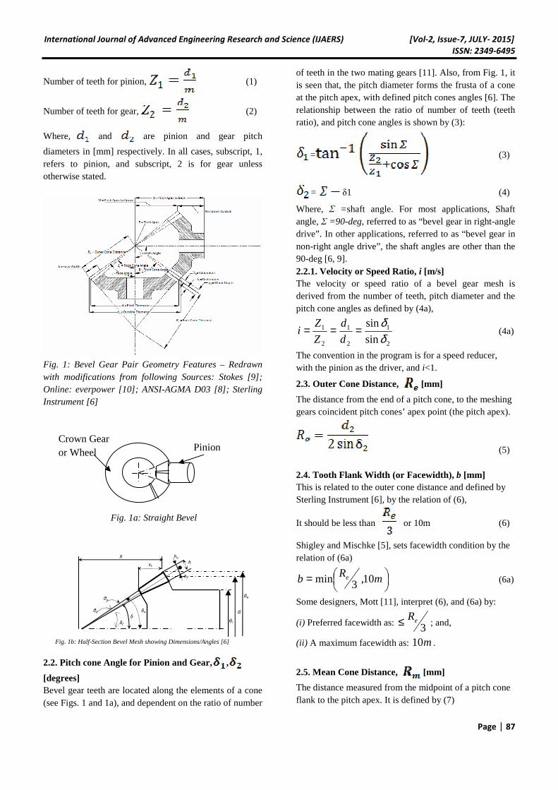
da
Fig. 1b: Half-Section Bevel Mesh showing Dimensions/Angles [6]
θf
θa
δa
δf
δ
hf
ha
h
X
Xb
di
d
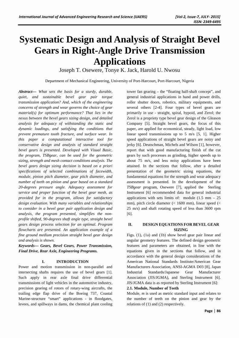
Crown Gear or Wheel
Fig. 1a: Straight Bevel
Pinion
International Journal of Advanced Engineering Research and Science (IJAERS) [Vol-2, Issue-7, JULY- 2015]
ISSN: 2349-6495
Page | 88
(7)
2.6. Addendum, [mm]
(8)
2.7. Dedendum, [mm]
mh f 188.1= (9)
2.8. Working Depth, [mm]
An indication of the depth of engagement of two gears, defined mathematically by (10):
(10)
2.9. Whole Depth, [mm]
This is the total depth of a tooth space, i.e., the sum of the addendum and the dedendum, and given as (11), [6, 9]:
05.0188.2 += mhl (11)
Stokes [9], states that, in order to maintain uniform clearance between the tip of the gear teeth, and the root of the teeth on the mating gear, bevel gears are designed such that the face cone apex does not coincide with the pitch cone apex. The clearance is the difference between the Whole Depth and Working Depth as defined by (11a) 2.9.1 Clearance, c [mm] c =0.188m + 0.05 (11a) The tolerance indicates that design can be varied to suit design and other requirements [8].
2.10. Dedendum Angle, [degrees]
See Fig. 1b.
(12)
2.11. Addendum Angle, [degrees]
Again, see Fig. 1b.
(13) 2.12. Outer Cone Angle for pinion and gear,
[degrees]
= + (14)
= + (14a)
2.13. Root Cone Angle for pinion and gear,
[degrees]
= - (15)
= - (15a)
2.14. Outside Diameter for pinion and gear,
[mm]
(16)
(16a) 2.15. Mounting Distance for pinion and gear,
[mm]
For good performance, to prevent rough binding and noisy operation, the distance from the back of the gear hub to the pitch cones’ apex point (see also, Fig. 1: O-pitch apex–to-back) must be properly defined. Referred to as the mounting distance (see Fig. 1b), it enables proper location of the axis of the mating gear; if less than the defined, contact friction induced binding and interference could occur, and when greater than recommended, could lead to noisy operation through jamming due to the excessive backlash [11, 6].
(17)
(17a) 2.16. Axial Flank width for pinion and
gear, , [mm]
The measured horizontal distance, from the back of the pitch cone to the front, at the inclined pitch cone angle.
(18)
(18a) 2.17. Inner Outside Diameter for pinion and gear,
[mm]
a
aai
bdd
θδ
cos
sin2 111 −= (19)
a
aai
bdd
θδ
cos
sin2 222 −=
(19a) 2.18. Circular tooth thickness, s, [mm]
2
ms
π= (20)
2.19. Number of teeth of An Equivalent Spur gear for
pinion and gear,
(21)
International Journal of Advanced Engineering Research and Science (IJAERS) [Vol-2, Issue-7, JULY- 2015]
ISSN: 2349-6495
Page | 89
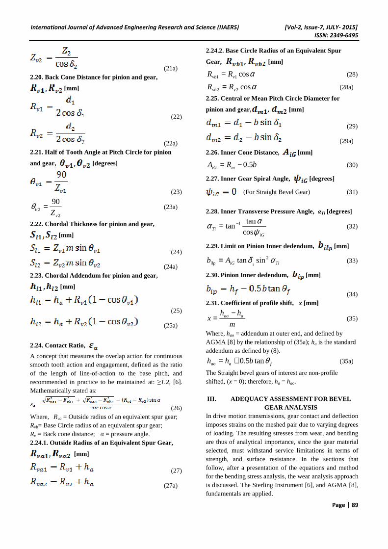
(21a) 2.20. Back Cone Distance for pinion and gear,
[mm]
(22)
(22a) 2.21. Half of Tooth Angle at Pitch Circle for pinion
and gear, [degrees]
(23)
22
90
vZ=νθ (23a)
2.22. Chordal Thickness for pinion and gear,
[mm]
(24)
(24a) 2.23. Chordal Addendum for pinion and gear,
[mm]
(25)
(25a)
2.24. Contact Ratio,
A concept that measures the overlap action for continuous smooth tooth action and engagement, defined as the ratio of the length of line-of-action to the base pitch, and recommended in practice to be maintained at: ≥1.2, [6]. Mathematically stated as:
(26) Where, Rva = Outside radius of an equivalent spur gear; Rvb= Base Circle radius of an equivalent spur gear; Rv = Back cone distance; α = pressure angle. 2.24.1. Outside Radius of an Equivalent Spur Gear,
[mm]
(27)
(27a)
2.24.2. Base Circle Radius of an Equivalent Spur
Gear, , [mm]
αcos11 vvb RR = (28)
αcos22 vvb RR = (28a)
2.25. Central or Mean Pitch Circle Diameter for
pinion and gear, , [mm]
(29)
(29a)
2.26. Inner Cone Distance, [mm]
bRA miG 5.0−= (30)
2.27. Inner Gear Spiral Angle, [degrees]
(For Straight Bevel Gear) (31)
2.28. Inner Transverse Pressure Angle, αTi [degrees]
iGTi ψ
ααcos
tantan 1−= (32)
2.29. Limit on Pinion Inner dedendum, [mm]
TiiGilp Ab αδ 2sintan1
= (33)
2.30. Pinion Inner dedendum, [mm]
(34) 2.31. Coefficient of profile shift, x [mm]
m
hhx aao −
= (35)
Where, hao = addendum at outer end, and defined by AGMA [8] by the relationship of (35a); ha is the standard addendum as defined by (8).
faao bhh θtan5.0+= (35a)
The Straight bevel gears of interest are non-profile shifted, (x = 0); therefore, ha = hao. III. ADEQUACY ASSESSMENT FOR BEVEL
GEAR ANALYSIS In drive motion transmissions, gear contact and deflection imposes strains on the meshed pair due to varying degrees of loading. The resulting stresses from wear, and bending are thus of analytical importance, since the gear material selected, must withstand service limitations in terms of strength, and surface resistance. In the sections that follow, after a presentation of the equations and method for the bending stress analysis, the wear analysis approach is discussed. The Sterling Instrument [6], and AGMA [8], fundamentals are applied.
International Journal of Advanced Engineering Research and Science (IJAERS) [Vol-2, Issue-7, JULY- 2015]
ISSN: 2349-6495
Page | 90
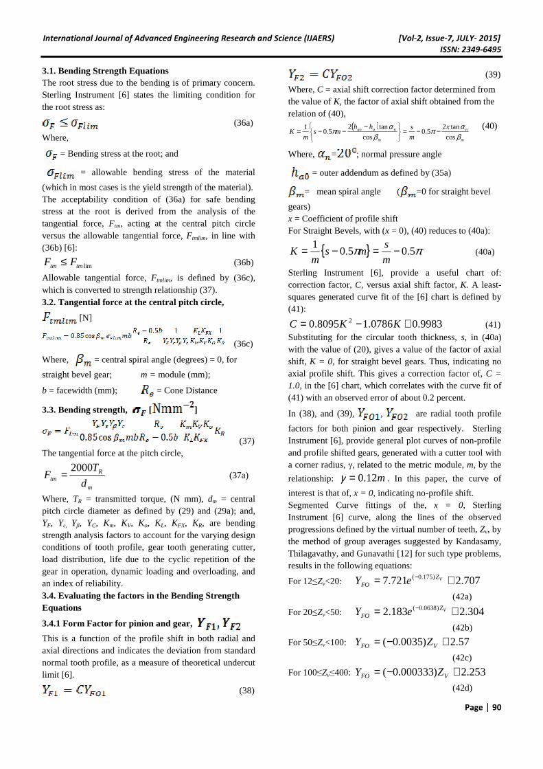
3.1. Bending Strength Equations The root stress due to the bending is of primary concern. Sterling Instrument [6] states the limiting condition for the root stress as:
(36a)
Where,
= Bending stress at the root; and
= allowable bending stress of the material
(which in most cases is the yield strength of the material). The acceptability condition of (36a) for safe bending stress at the root is derived from the analysis of the tangential force, Ftm, acting at the central pitch circle versus the allowable tangential force, Ftmlim, in line with (36b) [6]:
limtmtm FF ≤ (36b)
Allowable tangential force, Ftmlim, is defined by (36c), which is converted to strength relationship (37). 3.2. Tangential force at the central pitch circle,
[N]
(36c)
Where, = central spiral angle (degrees) = 0, for
straight bevel gear; m = module (mm);
b = facewidth (mm); = Cone Distance
3.3. Bending strength, [ ]
(37) The tangential force at the pitch circle,
m
Rtm d
TF
2000= (37a)
Where, TR = transmitted torque, (N mm), dm = central pitch circle diameter as defined by (29) and (29a); and, YF, Yε, Yβ, YC, Km, KV, Ko, KL, KFX, KR, are bending strength analysis factors to account for the varying design conditions of tooth profile, gear tooth generating cutter, load distribution, life due to the cyclic repetition of the gear in operation, dynamic loading and overloading, and an index of reliability. 3.4. Evaluating the factors in the Bending Strength Equations
3.4.1 Form Factor for pinion and gear,
This is a function of the profile shift in both radial and axial directions and indicates the deviation from standard normal tooth profile, as a measure of theoretical undercut limit [6].
(38)
(39)
Where, C = axial shift correction factor determined from the value of K, the factor of axial shift obtained from the relation of (40),
( )m
n
m
naao x
m
shhms
mK
βαπ
βαπ
cos
tan25.0
cos
tan25.0
1 −−=
−
−−= (40)
Where, = ; normal pressure angle
= outer addendum as defined by (35a)
= mean spiral angle ( =0 for straight bevel
gears) x = Coefficient of profile shift For Straight Bevels, with (x = 0), (40) reduces to (40a):
{ } ππ 5.05.01 −=−=
m
sms
mK (40a)
Sterling Instrument [6], provide a useful chart of: correction factor, C, versus axial shift factor, K. A least-squares generated curve fit of the [6] chart is defined by (41):
9983.00786.18095.0 2 +−= KKC (41) Substituting for the circular tooth thickness, s, in (40a) with the value of (20), gives a value of the factor of axial shift, K = 0, for straight bevel gears. Thus, indicating no axial profile shift. This gives a correction factor of, C = 1.0, in the [6] chart, which correlates with the curve fit of (41) with an observed error of about 0.2 percent.
In (38), and (39), , are radial tooth profile
factors for both pinion and gear respectively. Sterling Instrument [6], provide general plot curves of non-profile and profile shifted gears, generated with a cutter tool with a corner radius, γ, related to the metric module, m, by the
relationship: m12.0=γ . In this paper, the curve of
interest is that of, x = 0, indicating no-profile shift. Segmented Curve fittings of the, x = 0, Sterling Instrument [6] curve, along the lines of the observed progressions defined by the virtual number of teeth, Zv, by the method of group averages suggested by Kandasamy, Thilagavathy, and Gunavathi [12] for such type problems, results in the following equations:
For 12≤Zv<20: 707.2721.7 )175.0( += − VZFO eY
(42a)
For 20≤Zv<50: 304.2183.2 )0638.0( += − VZFO eY
(42b)
For 50≤Zv<100: 57.2)0035.0( +−= VFO ZY
(42c)
For 100≤Zv≤400: 253.2)000333.0( +−= VFO ZY
(42d)
International Journal of Advanced Engineering Research and Science (IJAERS) [Vol-2, Issue-7, JULY- 2015]
ISSN: 2349-6495
Page | 91
The relations (42a, 42b, 42c, and 42d), are applicable to the radial tooth profile factors of the pinion,YFO1, and gear, YFO2. Khurmi and Gupta [13], suggests that the tangential force to satisfy the conditions for pinion and gear bending strengths be evaluated for by an iterative solution based on the following conditions:
2211 FOFFOF YY ×≥× σσ (42e)
The product FOF Y×σ is called the strength factor. The
strength factor tends to impose a material constraint condition, viz.: If the condition of (42e) holds, then, the gear is weaker, and the design decision is made in favour
of the lower value of the product, FOF Y×σ , i.e., the
gear. Thus, (42e) is a reversible inequality. If the pinion and the gear are made of same material, and YFO1=YFO2, take the pinion as the weaker material constraint [13].
3.4.2. Load distribution factor,
To account for the effect of non-uniform load distribution due to such likely causes as eccentric mounting, deflections in shaft, tooth profile shift, the following correction for smooth operation is applied [6]:
(43)
Where, =radial contact ratio
3.4.3. Spiral Angle factor, Yβ
1201 mY
ββ −= (44)
Where, =0, for straight bevel gears, implying Yβ =1.
3.4.4. Cutter diameter effect
, For straight bevel gears of any size of
cutter diameter [6].
3.4.5. Life factor, , for Bending
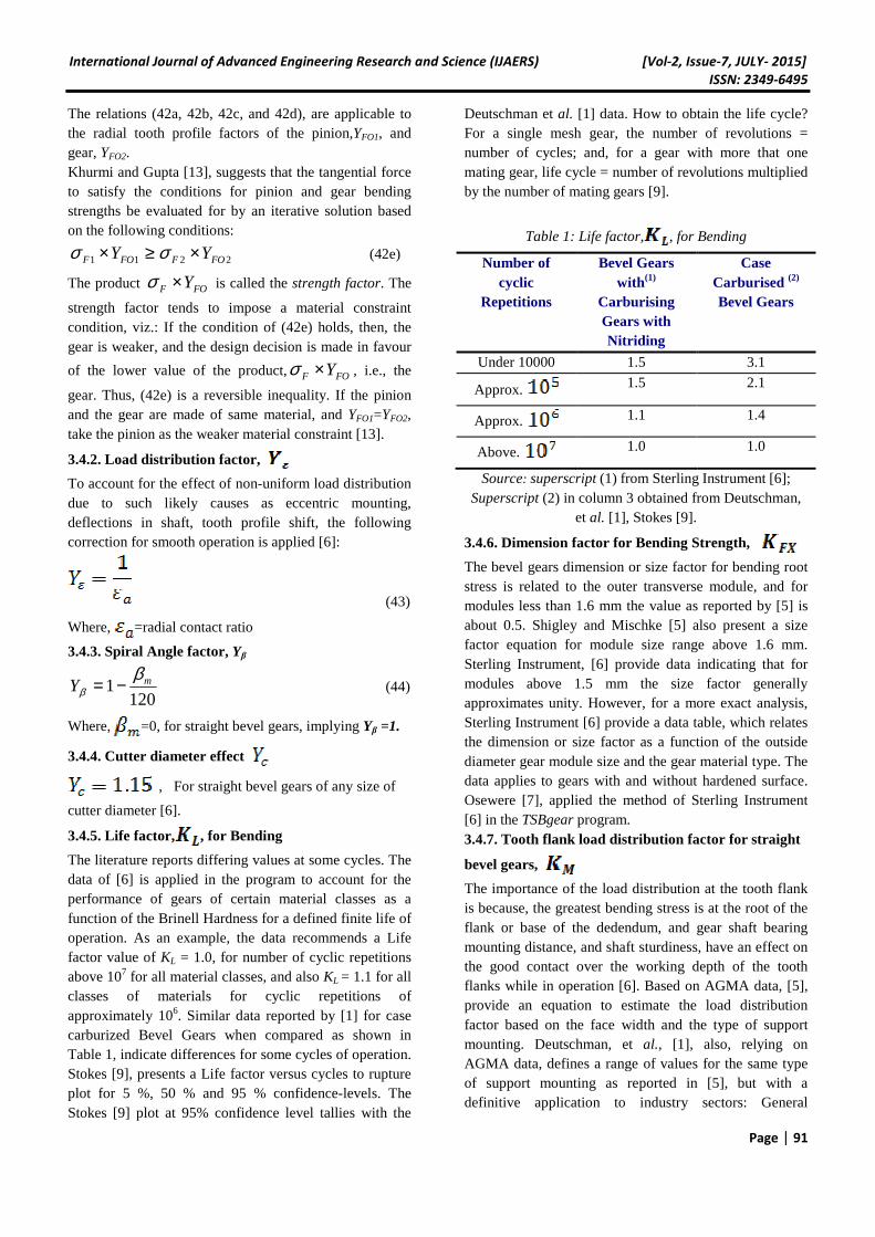
The literature reports differing values at some cycles. The data of [6] is applied in the program to account for the performance of gears of certain material classes as a function of the Brinell Hardness for a defined finite life of operation. As an example, the data recommends a Life factor value of KL = 1.0, for number of cyclic repetitions above 107 for all material classes, and also KL = 1.1 for all classes of materials for cyclic repetitions of approximately 106. Similar data reported by [1] for case carburized Bevel Gears when compared as shown in Table 1, indicate differences for some cycles of operation. Stokes [9], presents a Life factor versus cycles to rupture plot for 5 %, 50 % and 95 % confidence-levels. The Stokes [9] plot at 95% confidence level tallies with the
Deutschman et al. [1] data. How to obtain the life cycle? For a single mesh gear, the number of revolutions = number of cycles; and, for a gear with more that one mating gear, life cycle = number of revolutions multiplied by the number of mating gears [9].
Table 1: Life factor, , for Bending
Number of cyclic
Repetitions
Bevel Gears with (1)
Carburising Gears with Nitriding
Case Carburised (2)
Bevel Gears
Under 10000 1.5 3.1
Approx. 1.5 2.1
Approx. 1.1 1.4
Above. 1.0 1.0
Source: superscript (1) from Sterling Instrument [6]; Superscript (2) in column 3 obtained from Deutschman,
et al. [1], Stokes [9].
3.4.6. Dimension factor for Bending Strength,
The bevel gears dimension or size factor for bending root stress is related to the outer transverse module, and for modules less than 1.6 mm the value as reported by [5] is about 0.5. Shigley and Mischke [5] also present a size factor equation for module size range above 1.6 mm. Sterling Instrument, [6] provide data indicating that for modules above 1.5 mm the size factor generally approximates unity. However, for a more exact analysis, Sterling Instrument [6] provide a data table, which relates the dimension or size factor as a function of the outside diameter gear module size and the gear material type. The data applies to gears with and without hardened surface. Osewere [7], applied the method of Sterling Instrument [6] in the TSBgear program. 3.4.7. Tooth flank load distribution factor for straight
bevel gears,
The importance of the load distribution at the tooth flank is because, the greatest bending stress is at the root of the flank or base of the dedendum, and gear shaft bearing mounting distance, and shaft sturdiness, have an effect on the good contact over the working depth of the tooth flanks while in operation [6]. Based on AGMA data, [5], provide an equation to estimate the load distribution factor based on the face width and the type of support mounting. Deutschman, et al., [1], also, relying on AGMA data, defines a range of values for the same type of support mounting as reported in [5], but with a definitive application to industry sectors: General
International Journal of Advanced Engineering Research and Science (IJAERS) [Vol-2, Issue-7, JULY- 2015]
ISSN: 2349-6495
Page | 92
Industrial Applications, Automotive, and Aircraft. Sterling Instrument [6], again, using the mounting type as a guide, accounts for the factor, with the following classifications:
(i.) Rigid or Very stiff = shaft bearings in good close proximity to the gears, and therefore good contact;
(ii.) Some what weak = poor tooth contact. (iii) Average = a value just about lying at between (i) and (ii) .
In the straight bevel TSBgear program, the Sterling Instrument [6] method is adopted, and for conservative design, the Stiffness of shaft or gear box is assumed average. Thus, for such mid-value rating, based on type of mounting shaft support, the following is applied in the program:
−−−−−−⇒
−−−−−−⇒
−−−−−−⇒
≡endoneonportedgearsbothfor
endoneonportedgearonefor
sidestwoonportedgearsbothfor
KM
sup1.2
sup8.1
sup6.1
3.4.8. Dynamic Load factor,
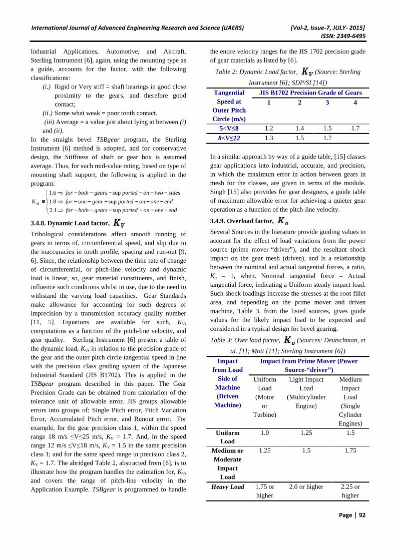
Tribological considerations affect smooth running of gears in terms of, circumferential speed, and slip due to the inaccuracies in tooth profile, spacing and run-out [9, 6]. Since, the relationship between the time rate of change of circumferential, or pitch-line velocity and dynamic load is linear, so, gear material constituents, and finish, influence such conditions whilst in use, due to the need to withstand the varying load capacities. Gear Standards make allowance for accounting for such degrees of imprecision by a transmission accuracy quality number [11, 5]. Equations are available for such, KV, computations as a function of the pitch-line velocity, and gear quality. Sterling Instrument [6] present a table of the dynamic load, KV, in relation to the precision grade of the gear and the outer pitch circle tangential speed in line with the precision class grading system of the Japanese Industrial Standard (JIS B1702). This is applied in the TSBgear program described in this paper. The Gear Precision Grade can be obtained from calculation of the tolerance unit of allowable error. JIS groups allowable errors into groups of: Single Pitch error, Pitch Variation Error, Accumulated Pitch error, and Runout error. For example, for the gear precision class 1, within the speed range 18 m/s ≤V≤25 m/s, KV = 1.7. And, in the speed range 12 m/s ≤V≤18 m/s, KV = 1.5 in the same precision class 1; and for the same speed range in precision class 2, KV = 1.7. The abridged Table 2, abstracted from [6], is to illustrate how the program handles the estimation for, KV, and covers the range of pitch-line velocity in the Application Example. TSBgear is programmed to handle
the entire velocity ranges for the JIS 1702 precision grade of gear materials as listed by [6].
Table 2: Dynamic Load factor, (Source: Sterling
Instrument [6]; SDP/SI [14])
Tangential Speed at
Outer Pitch Circle (m/s)
JIS B1702 Precision Grade of Gears
1 2 3 4
5<V≤8 1.2 1.4 1.5 1.7
8<V≤12 1.3 1.5 1.7
In a similar approach by way of a guide table, [15] classes gear applications into industrial, accurate, and precision, in which the maximum error in action between gears in mesh for the classes, are given in terms of the module. Singh [15] also provides for gear designers, a guide table of maximum allowable error for achieving a quieter gear operation as a function of the pitch-line velocity.
3.4.9. Overload factor,
Several Sources in the literature provide guiding values to account for the effect of load variations from the power source (prime mover-“driver”), and the resultant shock impact on the gear mesh (driven), and is a relationship between the nominal and actual tangential forces, a ratio, Ko = 1, when. Nominal tangential force = Actual tangential force, indicating a Uniform steady impact load. Such shock loadings increase the stresses at the root fillet area, and depending on the prime mover and driven machine, Table 3, from the listed sources, gives guide values for the likely impact load to be expected and considered in a typical design for bevel gearing.
Table 3: Over load factor, (Sources: Deutschman, et
al. [1]; Mott [11]; Sterling Instrument [6])
Impact from Load
Side of Machine (Driven
Machine)
Impact from Prime Mover (Power Source-“driver”)
Uniform Load
(Motor or
Turbine)
Light Impact Load
(Multicylinder Engine)
Medium Impact Load
(Single Cylinder Engines)
Uniform Load
1.0 1.25 1.5
Medium or Moderate
Impact Load
1.25 1.5 1.75
Heavy Load 1.75 or higher
2.0 or higher 2.25 or higher
International Journal of Advanced Engineering Research and Science (IJAERS) [Vol-2, Issue-7, JULY- 2015]
ISSN: 2349-6495
Page | 93
Mott [11] lists the expected likely impact or shock loadings of some driven machines, in the Uniform, Medium, and Heavy categories of Table 3. A more extensive table of adjusting for load variations for gear boxes is given by Singh [15].
3.4.10. Reliability Factor,
This factor allows for designing for a calculated risk, such as reduced life, rather than immediate failure [9]; and, depends on a confidence interval reliability index in the range 0.90-0.999, as defined in earlier AGMA standards and reported in [5]. Sterling Instrument [6], sets the following conditions which compares with the method reported by [5]. For General Case – a weighted average between
deterministic-and- Stochastic:
Deterministic: When all required factors can be
determined accurately:
Uncertainty: i.e. When all or some of the factors cannot
be determined accurately:
3.5. Surface Strength Equations The limiting condition to establish a proper surface strength is based on:
(45a)
Where, σH = Hertz Stress; σHlim = allowable Hertz Stress The allowable tangential force and Hertz stress are obtained from (45b) and (46) respectively.
(45b) Where, U is the reciprocal of the velocity or speed ratio, i.e. the teeth ratio, U = (1/i) = (Z2/Z1). 3.5.1. Hertz Stress
ROVHHXWVRLHL
MH
e
etmH CKKK
KZZZZK
ZZZZ
bR
R
U
U
bd
Fβ
βεδσ5.0
1cos2
2
1
1
−+=
(46)
The factors (ZH, ZM, Zε, Zβ, ZL, ZR , ZV, ZW, KHL, KHX, KHβ, KV, KO, CR) in the surface strength relations of (45b), and (46) are defined and obtained as follows:
3.5.2. Zone Factor,
The Zone factor for Hertz stress accounts for the effect of tooth flank curvature [9].
tt
bHZ
ααβ
cossin
cos2= (47)
Where: Central Axial pressure angle =
Normal pressure angle;
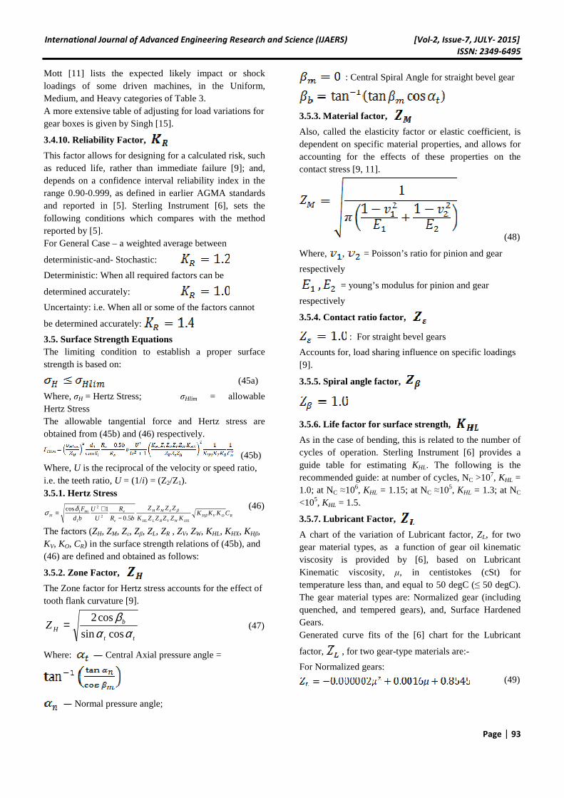
: Central Spiral Angle for straight bevel gear
3.5.3. Material factor,
Also, called the elasticity factor or elastic coefficient, is dependent on specific material properties, and allows for accounting for the effects of these properties on the contact stress [9, 11].
(48)
Where, , = Poisson’s ratio for pinion and gear
respectively
= young’s modulus for pinion and gear
respectively
3.5.4. Contact ratio factor,
: For straight bevel gears
Accounts for, load sharing influence on specific loadings [9].
3.5.5. Spiral angle factor,
3.5.6. Life factor for surface strength,
As in the case of bending, this is related to the number of cycles of operation. Sterling Instrument [6] provides a guide table for estimating KHL. The following is the recommended guide: at number of cycles, NC >107, KHL = 1.0; at NC ≈106, KHL = 1.15; at NC ≈105, KHL = 1.3; at NC <105, KHL = 1.5.
3.5.7. Lubricant Factor,
A chart of the variation of Lubricant factor, ZL, for two gear material types, as a function of gear oil kinematic viscosity is provided by [6], based on Lubricant Kinematic viscosity, μ, in centistokes (cSt) for temperature less than, and equal to 50 degC (≤ 50 degC). The gear material types are: Normalized gear (including quenched, and tempered gears), and, Surface Hardened Gears. Generated curve fits of the [6] chart for the Lubricant
factor, , for two gear-type materials are:-
For Normalized gears: (49)
International Journal of Advanced Engineering Research and Science (IJAERS) [Vol-2, Issue-7, JULY- 2015]
ISSN: 2349-6495
Page | 94
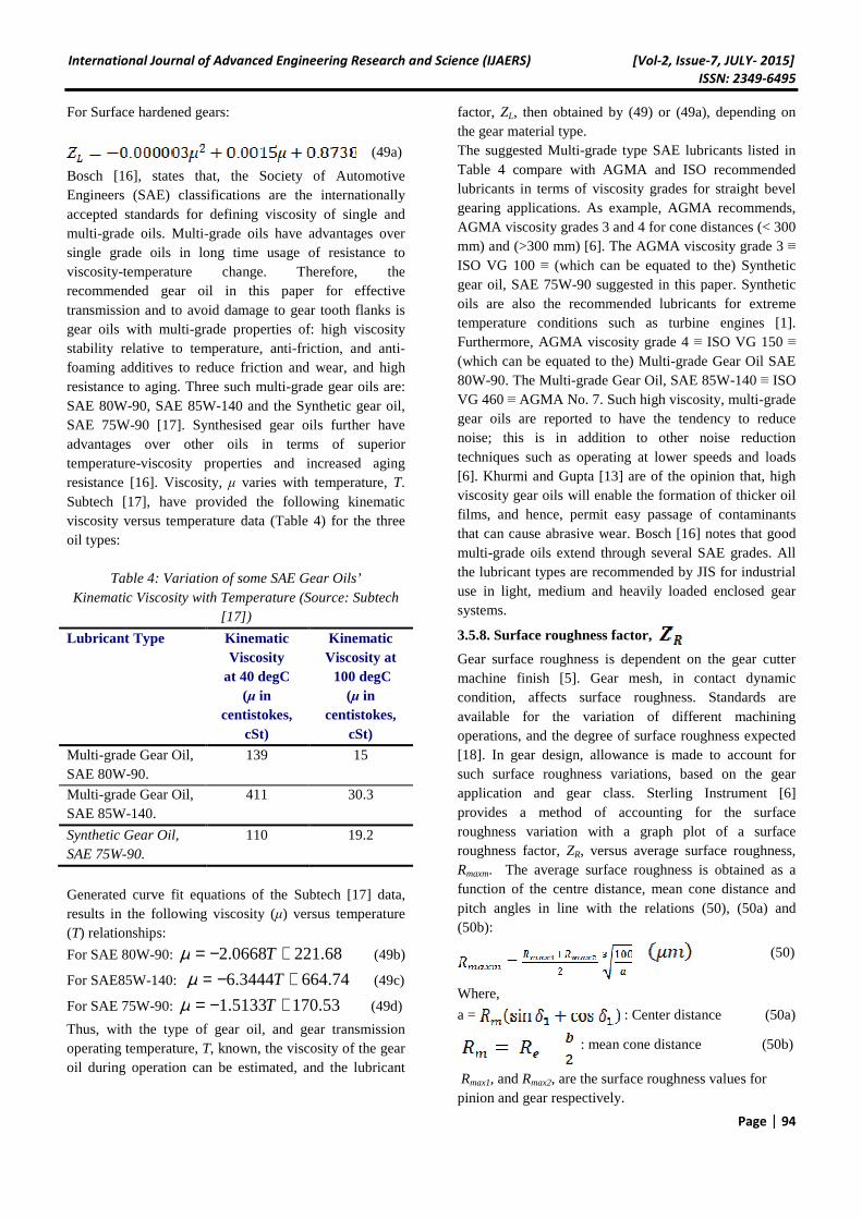
For Surface hardened gears:
(49a)
Bosch [16], states that, the Society of Automotive Engineers (SAE) classifications are the internationally accepted standards for defining viscosity of single and multi-grade oils. Multi-grade oils have advantages over single grade oils in long time usage of resistance to viscosity-temperature change. Therefore, the recommended gear oil in this paper for effective transmission and to avoid damage to gear tooth flanks is gear oils with multi-grade properties of: high viscosity stability relative to temperature, anti-friction, and anti-foaming additives to reduce friction and wear, and high resistance to aging. Three such multi-grade gear oils are: SAE 80W-90, SAE 85W-140 and the Synthetic gear oil, SAE 75W-90 [17]. Synthesised gear oils further have advantages over other oils in terms of superior temperature-viscosity properties and increased aging resistance [16]. Viscosity, μ varies with temperature, T. Subtech [17], have provided the following kinematic viscosity versus temperature data (Table 4) for the three oil types:
Table 4: Variation of some SAE Gear Oils’ Kinematic Viscosity with Temperature (Source: Subtech
[17])
Lubricant Type Kinematic Viscosity
at 40 degC (μ in
centistokes, cSt)
Kinematic Viscosity at 100 degC
(μ in centistokes,
cSt)
Multi-grade Gear Oil, SAE 80W-90.
139 15
Multi-grade Gear Oil, SAE 85W-140.
411 30.3
Synthetic Gear Oil, SAE 75W-90.
110 19.2
Generated curve fit equations of the Subtech [17] data, results in the following viscosity (μ) versus temperature (T) relationships:
For SAE 80W-90: 68.2210668.2 +−= Tµ (49b)
For SAE85W-140: 74.6643444.6 +−= Tµ (49c)
For SAE 75W-90: 53.1705133.1 +−= Tµ (49d)
Thus, with the type of gear oil, and gear transmission operating temperature, T, known, the viscosity of the gear oil during operation can be estimated, and the lubricant
factor, ZL, then obtained by (49) or (49a), depending on the gear material type. The suggested Multi-grade type SAE lubricants listed in Table 4 compare with AGMA and ISO recommended lubricants in terms of viscosity grades for straight bevel gearing applications. As example, AGMA recommends, AGMA viscosity grades 3 and 4 for cone distances (< 300 mm) and (>300 mm) [6]. The AGMA viscosity grade 3 ≡ ISO VG 100 ≡ (which can be equated to the) Synthetic gear oil, SAE 75W-90 suggested in this paper. Synthetic oils are also the recommended lubricants for extreme temperature conditions such as turbine engines [1]. Furthermore, AGMA viscosity grade 4 ≡ ISO VG 150 ≡ (which can be equated to the) Multi-grade Gear Oil SAE 80W-90. The Multi-grade Gear Oil, SAE 85W-140 ≡ ISO VG 460 ≡ AGMA No. 7. Such high viscosity, multi-grade gear oils are reported to have the tendency to reduce noise; this is in addition to other noise reduction techniques such as operating at lower speeds and loads [6]. Khurmi and Gupta [13] are of the opinion that, high viscosity gear oils will enable the formation of thicker oil films, and hence, permit easy passage of contaminants that can cause abrasive wear. Bosch [16] notes that good multi-grade oils extend through several SAE grades. All the lubricant types are recommended by JIS for industrial use in light, medium and heavily loaded enclosed gear systems.
3.5.8. Surface roughness factor,
Gear surface roughness is dependent on the gear cutter machine finish [5]. Gear mesh, in contact dynamic condition, affects surface roughness. Standards are available for the variation of different machining operations, and the degree of surface roughness expected [18]. In gear design, allowance is made to account for such surface roughness variations, based on the gear application and gear class. Sterling Instrument [6] provides a method of accounting for the surface roughness variation with a graph plot of a surface roughness factor, ZR, versus average surface roughness, Rmaxm. The average surface roughness is obtained as a function of the centre distance, mean cone distance and pitch angles in line with the relations (50), (50a) and (50b):
(50)
Where,
a = : Center distance (50a)
: mean cone distance (50b)
Rmax1, and Rmax2, are the surface roughness values for pinion and gear respectively.
International Journal of Advanced Engineering Research and Science (IJAERS) [Vol-2, Issue-7, JULY- 2015]
ISSN: 2349-6495
Page | 95
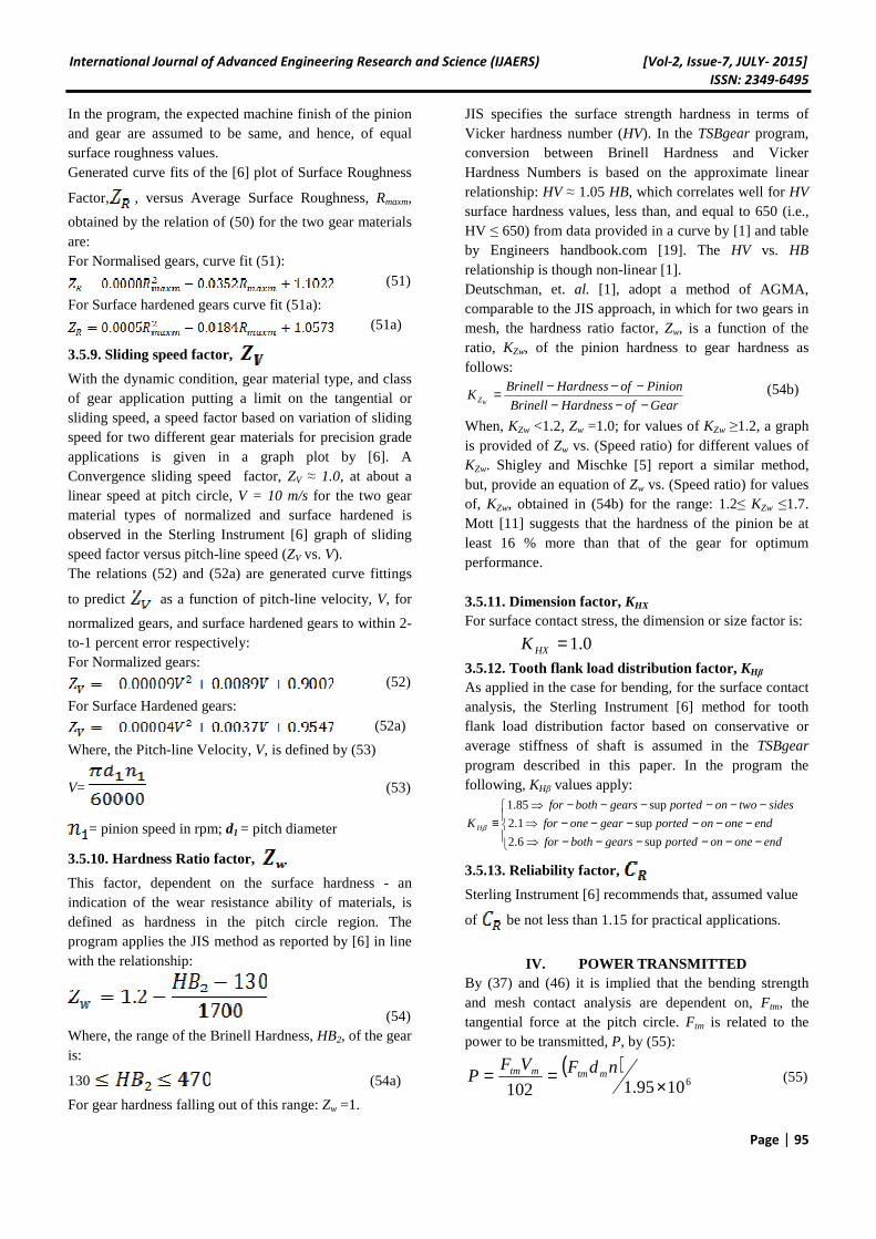
In the program, the expected machine finish of the pinion and gear are assumed to be same, and hence, of equal surface roughness values. Generated curve fits of the [6] plot of Surface Roughness
Factor, , versus Average Surface Roughness, Rmaxm,
obtained by the relation of (50) for the two gear materials are: For Normalised gears, curve fit (51):
(51)
For Surface hardened gears curve fit (51a): (51a)
3.5.9. Sliding speed factor,
With the dynamic condition, gear material type, and class of gear application putting a limit on the tangential or sliding speed, a speed factor based on variation of sliding speed for two different gear materials for precision grade applications is given in a graph plot by [6]. A Convergence sliding speed factor, ZV ≈ 1.0, at about a linear speed at pitch circle, V = 10 m/s for the two gear material types of normalized and surface hardened is observed in the Sterling Instrument [6] graph of sliding speed factor versus pitch-line speed (ZV vs. V). The relations (52) and (52a) are generated curve fittings
to predict as a function of pitch-line velocity, V, for
normalized gears, and surface hardened gears to within 2-to-1 percent error respectively: For Normalized gears:
(52)
For Surface Hardened gears: (52a)
Where, the Pitch-line Velocity, V, is defined by (53)
V= (53)
= pinion speed in rpm; d1 = pitch diameter
3.5.10. Hardness Ratio factor,
This factor, dependent on the surface hardness - an indication of the wear resistance ability of materials, is defined as hardness in the pitch circle region. The program applies the JIS method as reported by [6] in line with the relationship:
(54) Where, the range of the Brinell Hardness, HB2, of the gear is:
130 (54a)
For gear hardness falling out of this range: Zw =1.
JIS specifies the surface strength hardness in terms of Vicker hardness number (HV). In the TSBgear program, conversion between Brinell Hardness and Vicker Hardness Numbers is based on the approximate linear relationship: HV ≈ 1.05 HB, which correlates well for HV surface hardness values, less than, and equal to 650 (i.e., HV ≤ 650) from data provided in a curve by [1] and table by Engineers handbook.com [19]. The HV vs. HB relationship is though non-linear [1]. Deutschman, et. al. [1], adopt a method of AGMA, comparable to the JIS approach, in which for two gears in mesh, the hardness ratio factor, Zw, is a function of the ratio, KZw, of the pinion hardness to gear hardness as follows:
GearofHardnessBrinell
PinionofHardnessBrinellK
WZ −−−−−−= (54b)
When, KZw <1.2, Zw =1.0; for values of KZw ≥1.2, a graph is provided of Zw vs. (Speed ratio) for different values of KZw. Shigley and Mischke [5] report a similar method, but, provide an equation of Zw vs. (Speed ratio) for values of, KZw, obtained in (54b) for the range: 1.2≤ KZw ≤1.7. Mott [11] suggests that the hardness of the pinion be at least 16 % more than that of the gear for optimum performance. 3.5.11. Dimension factor, KHX For surface contact stress, the dimension or size factor is:
0.1=HXK
3.5.12. Tooth flank load distribution factor, KHβ As applied in the case for bending, for the surface contact analysis, the Sterling Instrument [6] method for tooth flank load distribution factor based on conservative or average stiffness of shaft is assumed in the TSBgear program described in this paper. In the program the following, KHβ values apply:
−−−−−−⇒
−−−−−−⇒
−−−−−−⇒
≡endoneonportedgearsbothfor
endoneonportedgearonefor
sidestwoonportedgearsbothfor
K H
sup6.2
sup1.2
sup85.1
β
3.5.13. Reliability factor,
Sterling Instrument [6] recommends that, assumed value
of be not less than 1.15 for practical applications.
IV. POWER TRANSMITTED
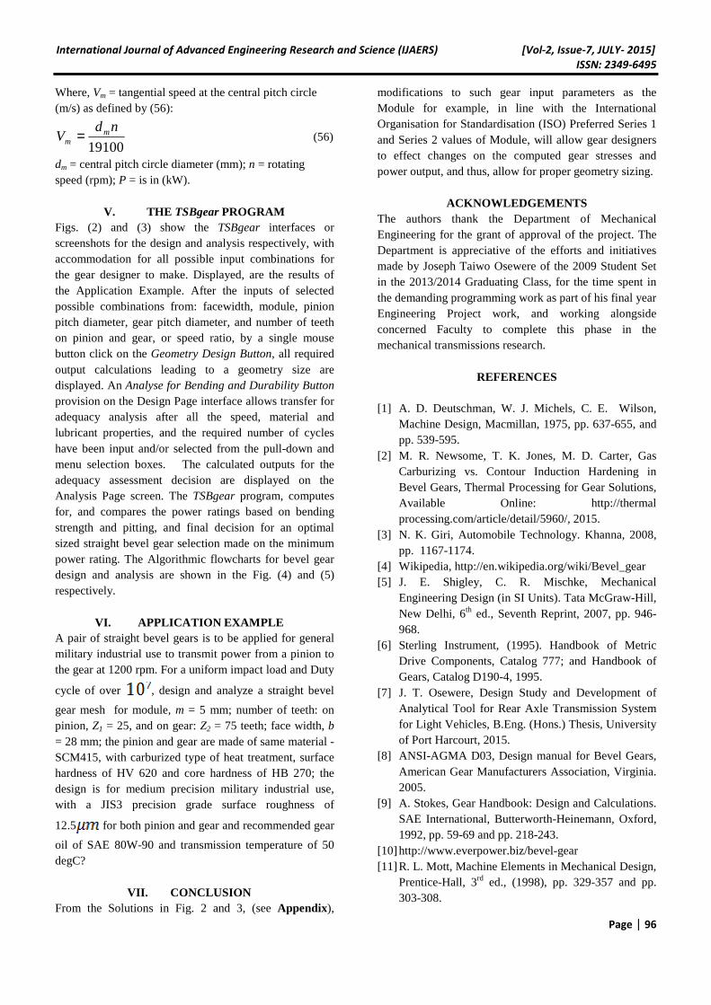
By (37) and (46) it is implied that the bending strength and mesh contact analysis are dependent on, Ftm, the tangential force at the pitch circle. Ftm is related to the power to be transmitted, P, by (55):
( )61095.1102 ×== ndFVF
P mtmmtm (55)
International Journal of Advanced Engineering Research and Science (IJAERS) [Vol-2, Issue-7, JULY- 2015]
ISSN: 2349-6495
Page | 96
Where, Vm = tangential speed at the central pitch circle (m/s) as defined by (56):
19100
ndV m
m = (56)
dm = central pitch circle diameter (mm); n = rotating speed (rpm); P = is in (kW).
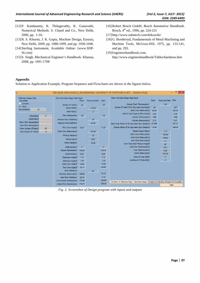
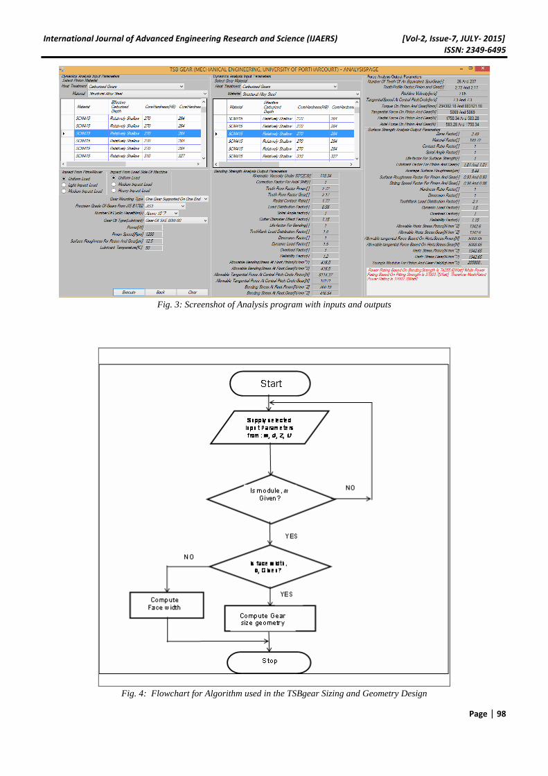
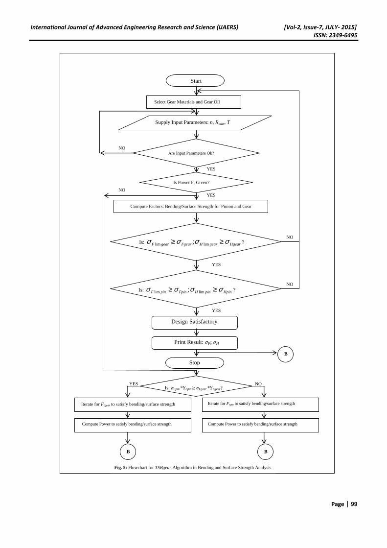
V. THE TSBgear PROGRAM Figs. (2) and (3) show the TSBgear interfaces or screenshots for the design and analysis respectively, with accommodation for all possible input combinations for the gear designer to make. Displayed, are the results of the Application Example. After the inputs of selected possible combinations from: facewidth, module, pinion pitch diameter, gear pitch diameter, and number of teeth on pinion and gear, or speed ratio, by a single mouse button click on the Geometry Design Button, all required output calculations leading to a geometry size are displayed. An Analyse for Bending and Durability Button provision on the Design Page interface allows transfer for adequacy analysis after all the speed, material and lubricant properties, and the required number of cycles have been input and/or selected from the pull-down and menu selection boxes. The calculated outputs for the adequacy assessment decision are displayed on the Analysis Page screen. The TSBgear program, computes for, and compares the power ratings based on bending strength and pitting, and final decision for an optimal sized straight bevel gear selection made on the minimum power rating. The Algorithmic flowcharts for bevel gear design and analysis are shown in the Fig. (4) and (5) respectively.
VI. APPLICATION EXAMPLE A pair of straight bevel gears is to be applied for general military industrial use to transmit power from a pinion to the gear at 1200 rpm. For a uniform impact load and Duty
cycle of over , design and analyze a straight bevel
gear mesh for module, m = 5 mm; number of teeth: on pinion, Z1 = 25, and on gear: Z2 = 75 teeth; face width, b = 28 mm; the pinion and gear are made of same material - SCM415, with carburized type of heat treatment, surface hardness of HV 620 and core hardness of HB 270; the design is for medium precision military industrial use, with a JIS3 precision grade surface roughness of
12.5 for both pinion and gear and recommended gear
oil of SAE 80W-90 and transmission temperature of 50 degC?
VII. CONCLUSION From the Solutions in Fig. 2 and 3, (see Appendix),
modifications to such gear input parameters as the Module for example, in line with the International Organisation for Standardisation (ISO) Preferred Series 1 and Series 2 values of Module, will allow gear designers to effect changes on the computed gear stresses and power output, and thus, allow for proper geometry sizing.
ACKNOWLEDGEMENTS The authors thank the Department of Mechanical Engineering for the grant of approval of the project. The Department is appreciative of the efforts and initiatives made by Joseph Taiwo Osewere of the 2009 Student Set in the 2013/2014 Graduating Class, for the time spent in the demanding programming work as part of his final year Engineering Project work, and working alongside concerned Faculty to complete this phase in the mechanical transmissions research.
REFERENCES [1] A. D. Deutschman, W. J. Michels, C. E. Wilson,
Machine Design, Macmillan, 1975, pp. 637-655, and pp. 539-595.
[2] M. R. Newsome, T. K. Jones, M. D. Carter, Gas Carburizing vs. Contour Induction Hardening in Bevel Gears, Thermal Processing for Gear Solutions, Available Online: http://thermal processing.com/article/detail/5960/, 2015.
[3] N. K. Giri, Automobile Technology. Khanna, 2008, pp. 1167-1174.
[4] Wikipedia, http://en.wikipedia.org/wiki/Bevel_gear [5] J. E. Shigley, C. R. Mischke, Mechanical
Engineering Design (in SI Units). Tata McGraw-Hill, New Delhi, 6th ed., Seventh Reprint, 2007, pp. 946-968.
[6] Sterling Instrument, (1995). Handbook of Metric Drive Components, Catalog 777; and Handbook of Gears, Catalog D190-4, 1995.
[7] J. T. Osewere, Design Study and Development of Analytical Tool for Rear Axle Transmission System for Light Vehicles, B.Eng. (Hons.) Thesis, University of Port Harcourt, 2015.
[8] ANSI-AGMA D03, Design manual for Bevel Gears, American Gear Manufacturers Association, Virginia. 2005.
[9] A. Stokes, Gear Handbook: Design and Calculations. SAE International, Butterworth-Heinemann, Oxford, 1992, pp. 59-69 and pp. 218-243.
[10] http://www.everpower.biz/bevel-gear [11] R. L. Mott, Machine Elements in Mechanical Design,
Prentice-Hall, 3rd ed., (1998), pp. 329-357 and pp. 303-308.
International Journal of Advanced Engineering Research and Science (IJAERS) [Vol-2, Issue-7, JULY- 2015]
ISSN: 2349-6495
Page | 97
[12] P. Kandasamy, K. Thilagavathy, K. Gunavathi, Numerical Methods. S. Chand and Co., New Delhi, 2006, pp. 1-16.
[13] R. S. Khurmi, J. K. Gupta, Machine Design, Eurasia, New Delhi, 2009, pp. 1088-1099, and pp. 1036-1046.
[14] Sterling Instrument, Available Online: (www.SDP-SI.com)
[15] S. Singh, Mechanical Engineer’s Handbook. Khanna, 2008, pp. 1691-1708
[16] Robert Bosch GmbH, Bosch Automotive Handbook. Bosch, 4th ed., 1996, pp. 224-231
[17] http://www.substech.com/dokuwiki/ [18] G. Boothroyd, Fundamentals of Metal Machining and
Machine Tools, McGraw-Hill, 1975, pp. 133-141, and pp. 293.
[19] Engineershandbook.com, http://www.engineeshandbook/Tables/hardness.htm
Appendix Solution to Application Example, Program Sequence and Flowcharts are shown in the figures below.
Fig. 2: Screenshot of Design program with inputs and outputs
International Journal of Advanced Engineering Research and Science (IJAERS) [Vol-2, Issue-7, JULY- 2015]
ISSN: 2349-6495
Page | 98
Fig. 3: Screenshot of Analysis program with inputs and outputs
Fig. 4: Flowchart for Algorithm used in the TSBgear Sizing and Geometry Design
International Journal of Advanced Engineering Research and Science (IJAERS) [Vol-2, Issue-7, JULY- 2015]
ISSN: 2349-6495
Page | 99
YES
YES
YES
YES
NO
NO
NO YES
Start
Select Gear Materials and Gear Oil
Are Input Parameters Ok?
Supply Input Parameters: n, Rmax, T
Is Power P, Given?
Compute Factors: Bending/Surface Strength for Pinion and Gear
Is: HpinpinHFpinpinF σσσσ ≥≥ limlim ; ?
Is: HgeargearHFgeargearF σσσσ ≥≥ limlim ; ?
Design Satisfactory
Print Result: σF; σH
Stop
Is: σFpin *YFpin ≥ σFgear *YFgear?
Iterate for Ftgear to satisfy bending/surface strength Iterate for Ftpin to satisfy bending/surface strength
Compute Power to satisfy bending/surface strength Compute Power to satisfy bending/surface strength
B B
B
Fig. 5: Flowchart for TSBgear Algorithm in Bending and Surface Strength Analysis
NO
NO


![Bevel Gears in ProE[1]](https://img.pdfslide.us/doc/110x75/543da9fbb1af9f3d0a8b4920/bevel-gears-in-proe1.jpg)


![85540168 Bevel Gears in ProE[1]](https://img.pdfslide.us/doc/110x75/544b2fd6b1af9f804f8b4fca/85540168-bevel-gears-in-proe1.jpg)